

Page 1
General
A
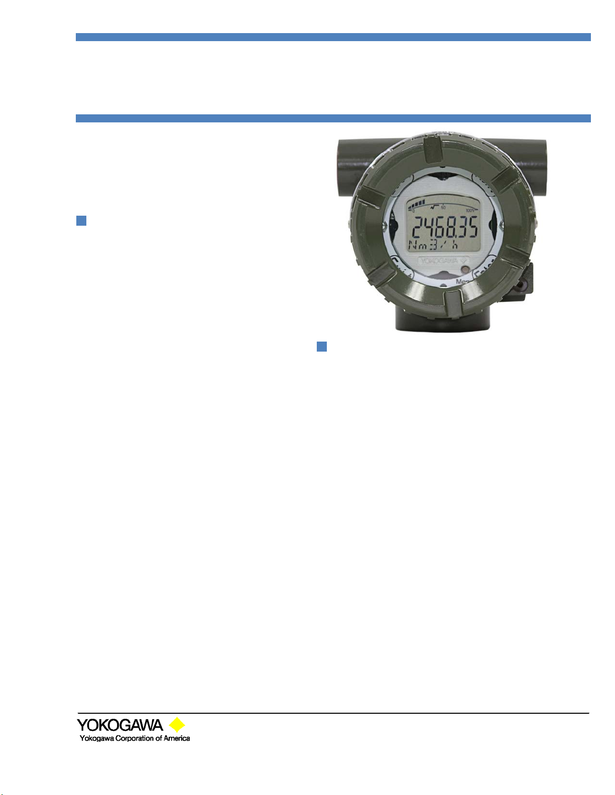
Model MLX
Specifications
Loop Powered Process Indicator
-
-
The Model MLX Loop-Powered Process
Indicator receives DC current signals from
electronic transmitters and indicates process
measurement values. Standard models are
general purpose.
STANDARD SPECIFICATIONS
□
FUNCTIONAL SPECIFICATIONS
Input: 4-20mA DC 2-wire
Voltage Drop: 3.5V at 20mA
LCD Display
Numerical: Six 7-segment digits
Alpha-numerical: Six 14-segment characters
Bar graph: 20-segment Bar graph.
Symbols: P, SP, T, F, %, √, x10, x100, x1000
Configuration: User configurable for desired
engineering units.
Method: User configurable from front panel
Zero & Span: Zero and span can be set between
±999999.
Turn-on Time: 12 second (includes power on self-test
and memory integrity check)
Update Time: 1 second
Isolation: Input/Output/Ground isolated to 500V DC
□
PERFORMANCE SPECIFICATIONS
Accuracy: ± 0.05% of full scale +1 digit
Operating Current: 3.6mA to 28mA
Ambient Temperature: -30 to +60°C (-22 to 140°F)
Ambient Humidity: 0 to 100%RH at 23°C (73°F)
Ambient Temperature Effect: 0.1°C per 10°C
Over range: 200mA without damage
Maximum error: +0.02%, -0.03% (of full scale)
Conformity (Linearity): 0.03%
Hysteresis error: 0.03%
Repeatability: 0.03%
Vibration: 3G @ 10-150Hz
Shock: 50G
Explosion Protection: FM, CSA, ATEX, and IEC
□
PHYSICAL SPECIFICATIONS
Enclosure
Material
Housing: Low copper cast aluminum alloy with
Polyurethane resin baked finish - Deep sea moss
green (equivalent of Munsell 0.6GY3.1/2.0) or
SUS316 cast stainless steel (ASTM CF-8M)
Name plate: Black anodized aluminum or 316 SST
Tag: 304 SST
Wired tag: 304 SST
Degrees of Protection: NEMA 4X, IP67
Mounting: Nominal 2” (50mm) pipe mount or
surface. (horizontal or vertical)
Weight: 1.25kg (2.70 lbs)*
*: Without mounting bracket
Add 0.8 kg (0.35 lbs) for mounting bracket
Electrical Connection: ½ NPT female or M20 female
FEATURES
User interface
A front panel push button switch combined with four
touch switches allows easy configuration of the indicator
(calibration, span, zero and engineering units).
Root extraction
For applications where the process variable is non-linear
and based on the square root, 3/2 root or 5/2 root, the
MLX can be configured to display the root function of the
input.
Field Configurable
Via the front panel user interface, the process variable
parameters can be modified as desired in the field.
LCD Display features
The LCD display includes a bar graph for an analog
indication of the process variable magnitude. The 6 digit
display and 6 character display (combined with several
symbols) give an instant view of all process variable
parameters. A menu system allows customizing
parameters such as decimal point position, engineering
units, status of symbols and state of bar graph.
Self-diagnostics
Built-in diagnostics operate at power-up and during
operation for ease of maintenance and troubleshooting.
Yokogawa Corporation of America
2 Dar t Ro ad, Ne wna n, GA 30265
770-254-0400
GS 6 0A02S01-01E-
©Copyright Februa ry 2012
2nd Edit ion
Page 2
A
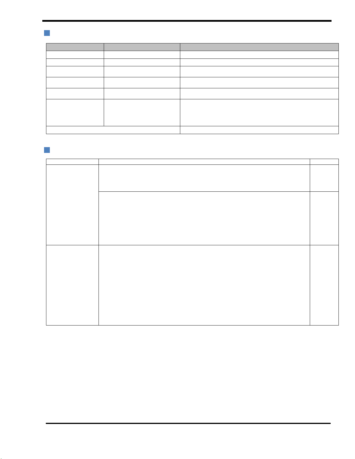
MODEL AND SUFFIX CODES
Model Suffix Codes Description
MLX ………………………………........... Loop Indicator
Input signal -A…………………………………... 4 to 20mA DC
Mounting
Housing
Communication -1………………….
Electrical Connection
Optional Codes
OPTIONAL SPECIFICATIONS (For Explosion Protected Type)
1…………………………............
2…………………………............
1…………………………........
2…………………………........
-2………………….
0……………..
1……………..
2……………..
3……………..
4……………..
2 inch Horizontal Pipe
2 inch Vertical Pipe (or wall mount)
Cast aluminum alloy
SUS316 cast stainless steel and ASTM CF-8M
Standard
HART Communications (To be announced later)
ANSI ½ NPT female, two electrical connections without blind plugs
ANSI ½ NPT female, two electrical connections and a 304 SST blind plug
ANSI ½ NPT female, two electrical connections and a 316 SST blind plug
ISO M20 female, two electrical connections without blind plugs
ISO M20 female, two electrical connections and a 316 SST blind plug
/ □Optional specification
Item Description Code
Factory Mutual (FM)
CENELEC ATEX
FM Explosion-proof Approval
Applicable Standard: FM3600, FM3615, FM3810, ANSI/NEMA 250
Explosionproof for Class I, Division 1, Groups A, B, C and D, Dust-ignitionproof for Class II/III,
Division 1, Groups E, F and G, in Hazardous locations, indoors and outdoors (NEMA 4X)
Temperature class: T5, Ambient Temperature: –30 to 60°C (–22 to 140°F)
FM Intrinsically Safe/FM Explosion-proof/FM Non-incendive Approval (Pending)
Applicable Standard: FM3600, FM3610, FM3611, FM3615, FM3810, ANSI/NEMA 250
Intrinsically Safe for Class I, Division 1, Groups A, B, C & D, Class II, Division 1,
Groups E, F & G and Class III, Division 1, Class I, Zone 0, in Hazardous Locations, AEx ia IIC
Non-incendive for Class I, Division 2, Groups A, B, C & D, Class II, Division. 2,
Groups E, F & G, and Class III, Division 1, Class I, Zone 2, Group IIC, in Hazardous Locations
Enclosure: "NEMA 4X", Temp. Class: T5, Amb. Temp.: –40 to 85°C (–40 to 185°F)
Intrinsically Safe Apparatus Parameters
[Groups A, B, C, D, E, F and G] Vmax=30 V, Imax=200 mA, Pmax=0.9 W, Ci=6 nF, Li=0 _H
[Groups C, D, E, F and G] Vmax=30 V, Imax=200 mA, Pmax=0.9 W, Ci=10 nF, Li=0 mH
ATEX Intrinsically Safe/ATEX Flameproof/Non-incendive Approval (Pending)
Flameproof
Applicable Standard: EN 60079-0, EN 60079-1, EN 60079-31
II 2G, 2D Ex d IIC T5 Ex tD A21 IP6X T85 Degree of protection : IP66 and IP67
Temperature class: T5, Ambient Temperature: –40 to 85°C (–40 to 185°F)
Intrinsically safe
Applicable Standard: EN 60079-0, EN 60079-11, EN 60079-26
II 1G, 1D Ex ia IIC T5 Degree of protection : IP66 and IP67
Temperature class: T5, Ambient Temperature: –40 to 85°C (–40 to 185°F)
Entity parameters : Ui=30 V, Ii=200 mA, Pi=0.9 W, Ci=10 nF, Li=0 mH
Non-incendive
Applicable Standard: EN 60079-0, EN 60079-11
II 3G Ex ic IIC T5
Temperature class: T5, Ambient Temperature: –40 to 85°C (–40 to 185°F)
Entity parameters : Ui=30 V, Ii=200 mA, Pi=0.9 W, Ci=10 nF, Li=0 mH
FF1
FU1
KU21
ll Rights Reserved. Copyright © 2012, Yokogawa Corporation of America GS 60A02S01-01E-A February 2012
Page 3

A
Item Description Code
Canadian Standards
Association (CSA)
Canadian Standards
Association (CSA)
IECEx Scheme
Combination of
Approvals
INMETRO (Brazil)
Certificate
GOST (Russian)
Certificate
CSA Intrinsically Safe/CSA Explosionproof Approval (Pending)
Applicable C22.2 No.25, C22.2 No.30, Standard: FM 3600, FM 3615, UL 1203, UL 50, UL
50E, C22.2 No.94, C22.2 No. 94.2
Explosionproof for Class I, Division 1, Groups A, B, C and D, Dust-ignitionproof for Class II/III,
Division 1, Groups E, F and G
Enclosure: TYPE 4X, Temp. Code: T5
Ex d IIC T5 Enclosure: IP66 and IP67
Amb.Temp.:–40 to 85°C(–40 to 185°F) for T5
Applicable Standard: C22.2 No.0, FM 3600, FM 3610, FMRC 3611, UL 60079-0, UL 60079-11,
C22.2 No.60079.0, CAN/CSA E60079-11, C22.2 No.213, CAN/CSA C22.2 No.157
Intrinsically Safe for Class I, Division 1, Groups A, B, C & D, Class II, Division 1, Groups E, F &
G, Class III, Division 1, Non-incendive for Class I, Division 2, Groups A, B, C & D, Class II,
Division 2, Groups E, F & G, Class III, Division 1
Enclosure: Type 4X, Temp. Code: T5 Amb. Temp.:–40 to 85°C(–40 to 185°F)
Electrical Parameters: [Intrinsically Safe] Vmax=30V, Imax=200mA, Pmax=0.9W, Ci=10nF,
Li=0
[Non-incendive] Vmax=30V, Ci=10nF, Li=0
[For CSA E60079]
Ex ia IIC T5, Ex ic IIC T5 Enclosure: IP66 and IP67
Amb. Temp.:–40 to 85°C(–40 to 185°F)
Electrical Parameters: [Ex ia] Ui=30V, Ii=200mA, Pi=0.9W, Ci=10nF, Li=0
[Ex ic] Ui=30V, Ci=10nF, Li=0
IEC Intrinsically Safe/IEC Flameproof Approval (Pending)
Intrinsically safe and type n
Applicable Standard: IEC 60079-0, IEC 60079-1, IEC 60079-11, IEC 60079-26, IEC 60079-31
II 1G, 1D Ex ia IIC T5, II 3G Ex ic IIC T5 Degree of protection : IP66 and IP67
Amb. Temp.:–40 to 85C(–40 to 185F)
Electrical Parameters: [Ex ia] Ui=30V, Ii=200mA, Pi=0.9W, Ci=10nF, Li=0
[Ex ic] Ui=30V,Ci=10nF, Li=0
Flameproof
Applicable Standard: IEC 60079-0, IEC60079-1
II 2G, 2D Ex d IIC T5 Ex tD A21 IP6X T85 Degree of protection : IP66 and IP67
Amb.Temp.:–40 to 85°C(–40 to 185°F) for T5
Combination of FU1, CU1 and KU21 Approvals (Pending) V1U
INMETRO Intrinsically Safe/INMETRO Flameproof Approval (Pending) BU1
Russian GOST certifícate (Pending) QR1
OPTIONAL SPECIFICATIONS
CU1
SU2
Item Description Code
Paint Epoxy resin paint
Calibration Calibration range and scale ENG
Stainless steel tag
plate
Polyurethane-Epoxy combination paint (Anti-corrosion coating)
Stainless steel tag screw attached to housing
Stainless steel tag wired to housing
X1
X2
SST
SSW
ORDERING INFORMATION OPTIONS
Specify the following when ordering:
1. Model and suffix codes. The MLX is fully field configurable from the front panel. To order a
2. Option codes.
3. Tag number
4. Calibration range desired (optional)
□
Example Ordering Information:
MLX-A11-10/FF1/ENG/SST
(Field Mounted Loop Indicator, 4 to 20mA DC, 2” Horizontal Pipe mount, aluminum housing, standard communication, ANSI ½ NPT electrical
connection without blind plugs, FM Explosion-proof approval)
0-200 InH2O Scale in Engineering Units. Please specify Scale and Engineering units when ordering /ENG.
FT-201 Specify Tag Number when ordering /SST and/or /SSW.
ll Rights Reserved. Copyright © 2012, Yokogawa Corporation of America GS 60A02S01-01E-A February 2012
pre-configured unit, specify the /ENG option followed by the desired
setpoints (zero, full scale, and engineering units).
Page 4

A
DIMENSIONS
MOUNTING
ll Rights Reserved. Copyright © 2012, Yokogawa Corporation of America GS 60A02S01-01E-A February 2012
Page 5

A
WIRING
The loop powered indicator series is powered by the current output loop and does not require external power. All devices must
be wired in series with the current loop. Twisted pair shielded cable is recommended.
The following is a typical wiring example of the MLX Loop Indicator connected to an EJA Pressure Transmitter (Note: The EJA
Transmitter below can be replaced with any 4-20mA 2 wire device.
ll Rights Reserved. Copyright © 2012, Yokogawa Corporation of America GS 60A02S01-01E-A February 2012
 Loading...