

Page 1

User’s
-
01E
-
01E
Manual
Hardware Manual
IM 34M6C11
Yokogawa Electric Corporation
IM 34M6C11
6th Edition
Page 2

Applicable Product:
●
● Range-free Multi-controller FA-M3
●●
The document number and document model code for this manual are given below.
Refer to the document numberin all communications; also refer to the documentnumber
or the document model code when purchasing additional copies of this manual.
Document No. : IM 34M6C11-01E
Document Model Code : DOCIM
i
Media No. IM 34M6C11-01E (FD) 6th Edition : May. 2001 (CR)
All Rights Reserved Copyright 1992, Yokogawa Electric Corporation
IM 34M6C11-01E 6th Edition : May 10, 2001-00
Page 3

Important
About This Manual
- This Manual should be passed on to the end user.
- Before using the controller, read this manual thoroughly to have a clear
understanding of the controller.
- This manualexplains the functionsof this product,but there is noguarantee that they
will suit the particular purpose of the user.
- Under absolutely no circumstances may thecontents ofthis manual betranscribed or
copied, in part or in whole, without permission.
- The contents of this manual are subject to change without prior notice.
- Every effort has been made to ensure accuracy in the preparation of this manual.
However, should any errors or omissions come to the attention of the user, please
contact the nearest Yokogawa Electric representative or sales office.
Safety Precautions when Using/Maintaining the Product
ii
- The following safety symbols are used on the product as well as in this manual.
Danger. This symbol on the product indicates that the operator must follow the
instructions laid out in this instruction manual to avoid the risk of personnel injuries,
fatalities, or damage to the instrument. Themanual describes what special care the
operator must exercise toprevent electricalshock or otherdangers thatmay result in
injury or the loss of life.
Protective Ground Terminal. Before using the instrument, be sure to ground this
terminal.
Function Ground Terminal. Before using the instrument, be sure to ground this
terminal.
Alternating current. Indicates alternating current.
Direct current. Indicates direct current.
IM 34M6C11-01E 6th Edition : May 10, 2001-00
Page 4

iii
The following symbols are used only in the instruction manual.
WARNING
Indicates a “Warning”.
Draws attention to information essential to prevent hardware damage, software
damage or system failure.
CAUTION
Indicates a “Caution”
Draws attention to information essential to the understanding of operation and
functions.
TIP
Indicates a “TIP”
Gives information that complements the present topic.
SEE ALSO
Indicates a “SEE ALSO” reference.
Identifies a source to which to refer.
- For theprotection andsafe use ofthe product andthe system controlled by it,be sure
to follow the instructions and precautions on safety stated in this manual whenever
handling the product. Take special note that if you handle the product in a manner
other than prescribed in these instructions, the protection feature of the product may
be damaged or impaired. In such cases, Yokogawa cannot guarantee the quality,
performance, function and safety of the product.
- When installing protection and/or safety circuits such as lightning protection devices
and equipment for the product and control system as well as designing or installing
separate protection and/or safety circuits for fool-proof design and fail-safe design of
processesand lines using theproduct and the system controlled by it, the usershould
implement it using devices and equipment, additional to this product.
- If component parts or consumable are to be replaced, be sure to use parts specified
by the company.
- This product is not designed or manufactured tobe used in critical applications which
directly affect or threaten human lives and safety — such as nuclear power
equipment, devices using radioactivity, railway facilities, aviation equipment, air
navigationfacilities, aviation facilitiesor medical equipment. If soused, itis the user’s
responsibility to include in the system additional equipment and devices that ensure
personnel safety.
- Do not attempt to modify the product.
Exemption from Responsibility
- Yokogawa Electric Corporation (hereinafter simply referred to as Yokogawa Electric)
makes no warranties regarding the product except those stated in the WARRANTY
that is provided separately.
- Yokogawa Electric assumes no liability to any party for any loss or damage, direct or
indirect, caused by the user or any unpredictable defect of the product.
IM 34M6C11-01E 6th Edition : May 10, 2001-00
Page 5

Software Supplied by the Comp any
- Yokogawa Electric makes no other warranties expressed or implied except as
provided in its warranty clause for software supplied by the company.
- Use the software with one computer only. You must purchase another copy of the
software for use with each additional computer.
- Copying the software for any purposes other than backup is strictlyprohibited.
- Store the original media, such as floppy disks, that contain the software in a safe
place.
- Reverse engineering, such as decompiling of the software, is strictly prohibited.
- No portion of the software supplied by Yokogawa Electric may be transferred,
exchanged, or sublet or leased for use by any third partywithout prior permission by
Yokogawa Electric.
iv
IM 34M6C11-01E 6th Edition : May 10, 2001-00
Page 6

General Requirements for Using the FA-M3 Controller
●
● Avoid installing the FA-M3 controller in the following locations:
●●
- Where the instrument will be exposed to direct sunlight, or where the operating
temperature exceeds the range 0°Cto55°C(0°F to 131°F).
- Where the relative humidity is outside the range 10 to 90%, or where sudden
temperature changes may occur and cause condensation.
- Where corrosive or flammable gases are present.
- Where the instrument will be exposed to direct mechanical vibration or shock.
- Where the instrument may be exposed to extreme levels of radioactivity.
●
● Use the correct types of wire for external wiring:
●●
- Use copper wire with temperature ratings greater than 75°C.
●
● Securely tighten screws:
●●
- Securely tighten module mounting screws and terminal screws to avoid problems
such as faulty operation.
- Tighten terminal block screws with the correct tightening torque as given in this
manual.
v
●
● Securely lock connecting cables:
●●
- Securely lock the connectors of cables, and check them thoroughly before turning on
the power.
●
● Interlock with emergency-stop circuitry using external relays:
●●
- Equipment incorporating the FA-M3 controller must be furnished with
emergency-stop circuitry that uses external relays. This circuitry should be set up to
interlock correctly with controller status (stop/run).
●
● Ground for low impedance:
●●
- For safety reasons, connect the [FG] grounding terminal to a Japanese Industrial
Standards (JIS) Class 3 Ground. For compliance to CE Marking, use cables such as
twisted cables which can ensure low impedance even at high frequencies for
grounding.
●
● Configure and route cables with noise control considerations:
●●
- Perform installation and wiring that segregates system parts that may likely become
noise sources and system parts that are susceptible to noise. Segregation can be
achieved by measures such as segregating by distance, installing a filter or
segregating the grounding system.
●
● Configure for CE Marking Conformance:
●●
- For compliance to CEMarking, performinstallationand cable routingaccording tothe
description on compliance to CE Marking in the “Hardware Manual”
(IM34M6C11-01E).
●
● Keep spare parts on hand:
●●
- Stock up on maintenance parts including spare modules, in advance.
IM 34M6C11-01E 6th Edition : May 10, 2001-00
Page 7

●
● Discharge static electricity before operating the system:
●●
- Becausestatic chargecan accumulatein dry conditions, firsttouch groundedmetal to
discharge any static electricity before touching the system.
●
● Never use solvents such as paint thinner for cleaning:
●●
- Gently clean the surfacesof the FA-M3 controllerwith a cloth that hasbeen soakedin
water or a neutral detergent and wringed.
- Do not use volatile solvents such as benzine or paint thinner or chemicals for
cleaning, as they may cause deformity,discoloration, or malfunctioning.
●
● Avoid storing the FA-M3 controller in places with high temperature or
●●
humidity:
- Since the CPU module has a built-in battery, avoid storage in places with high
temperature or humidity.
- Since the service life of the battery is drastically reduced by exposure to high
temperatures, take special care (storage temperature should be from –20 °Cto
75°C).
- There is a built-in lithium battery in a CPU module and temperature control module
which serves as backup power supply for programs, device information and
configuration information. The service life of this battery is more than 10 years in
standbymode at room temperature. Take notethat the service lifeof the battery may
be shortened when installed or stored at locations of extreme low or high
temperatures. Therefore, we recommend that modules with built-in batteries be
stored at room temperature.
vi
●
● Always turn off the power before installing or removing modules:
●●
- Failing to turn offthe powersupply wheninstalling or removing modules,may resultin
damage.
●
● Do not touch components in the module:
●●
- In some modules you can remove the right-side cover and install ROM packs or
change switch settings. While doing this, do not touch any components on the
printed-circuit board, otherwise components may be damaged and modules may fail
to work.
IM 34M6C11-01E 6th Edition : May 10, 2001-00
Page 8

Introduction
Overview of the Manual
This manual explains the configuration, specifications and installation of the Range-Free
Multi-controller FA-M3. It also discusses the individual specifications of power supply
modules, base modules, I/O modules, cables and terminal block units.
Configuration of the Manual
This manual consists of two parts.
z
z Part A Standard Version
zz
The main part of this manual explains all the detailsof the FA-M3system except for those
of the FA-M3 Value version.
z
z Part B FA-M3 Value (F3SC21-1N) Version
zz
The second part of the manual discusses the details specific to the FA-M3 Value
(F3SC21-1N).
vii
ChaptersA3 (Installation and Wiring), A4 (Test Runs and Troubleshooting)and A5
(Maintenance and Inspection) are common to both the standard FA-M3 and the FA-M3
Value. Be sure to read these chapters before using the FA-M3 Value.
Other Instruction Manuals
- For products other than the power supply module, base module, I/O module, cable
and terminal block unit, refer to their respective manuals.
Trademarks
- Microsoft Windows, Windows 95, Windows 98 and Windows NT are registered
trademarks of Microsoft Corporation, USA.
- Ethernet is a registered trademark of XEROX Corporation.
- The trade and company names that are referred to in this document are either
trademarks or registered trademarks of their respective companies.
IM 34M6C11-01E 6th Edition : May 10, 2001-00
Page 9

Blank Page
Page 10

FA-M3
I
Hardware Manual
CONTENTS
Applicable Product:...................................................................................i
Important...................................................................................................ii
Introduction.............................................................................................vii
A1. System Configuration...............................................................A1-1
A1.1 System Configuration........................................................................... A1-1
A1.2 Restrictions on Installing Modules......................................................A1-3
A1.3 Peripheral Tools Supporting the Program Development o f
FA-M3......................................................................................................A1-7
TOC-1
M 34M6C11-02E 6th Edition
A2. Specifications and Configuration.............................................A2-1
A2.1 Specifications........................................................................................ A2-1
A2.2 FA-M3 Controller Configuration ..........................................................A2-2
A2.3 Power Supply Modules.........................................................................A2-9
A2.4 Base Modules......................................................................................A2-13
A2.5 I/O Modules.......................................................................................... A2-14
(1) F3XH04-3N High-speed Input Module....................................... A2-16
(2) F3XA08-1N/F3XA08-2N AC Input Modules...............................A2-21
(3) F3XC08-0N No-voltage Contact Input Module ..........................A2-23
(4) F3XD08-6F DC Input Module ....................................................A2-24
(5) F3XD16-3F/F3XD16-4F/F3XD16-3H DC Input Modules...........A2-25
(6) F3XD32-3F/F3XD32-4F/F3XD32-5F DC Input Modules...........A2-27
(7) F3XD64-3F/F3XD64-4F DC Input Modules............................... A2-29
(8) F3XD08-6N DC Input Module.................................................... A2-31
(9) F3XD16-3N/F3XD16-4N DC-Input Modules.............................. A2-33
(10) F3XD32-3N/F3XD32-4N/F3XD32-5N DC Input Modules.......... A2-35
(1 1) F3XD64-3N/F3XD64-4N DC Input Modules..............................A2-37
(12) F3XD64-6M DC Input Module.................................................... A2-39
(13) F3YD04-7N Transistor Output Module ......................................A2-40
(14) F3YA08-2N Triac Output Module...............................................A2-42
(15) F3YC08-0C/F3YC08-0N Relay Output Module........................A2-44
(16) F3YD08-6A/F3YD08-6B Transistor Output Modules.................A2-46
(17) F3YD14-5A/F3YD14-5B Transistor Output Modules.................A2-48
(18) F3YC16-0N Relay Output Module ............................................. A2-50
(19) F3YD32-1A/F3YD32-1B Transistor Output Modules.................A2-52
(20) F3YD32-1T TTL Output Module.................................................A2-54
IM 34M6C11-01E 6th Edition : May 10, 2001-00
Page 11

TOC-2
(21) F3YD64-1F Transistor Output Module....................................... A2-56
(22) F3YD64-1ATransistor Output Module.......................................A2-58
(23) F3YD64-1M Transistor Output Module......................................A2-60
(24) F3WD64-3F/F3WD64-4F Input/Output Modules.......................A2-62
(25) F3WD64-3N/F3WD64-4N Input/output Modules.......................A2-66
A2.6 ROM Packs ..........................................................................................A2-70
A2.7 Cables...................................................................................................A2-72
(1) Cables for Programming Tool ....................................................A2-72
(2) CPU Port/9-pin D-sub Adapter Cable ........................................A2-73
(3) Cables for Connector Terminal Blocks....................................... A2-74
(4) Fiber-Optic Cord ........................................................................ A2-75
(5) Fiber-optic Cables......................................................................A2-76
A2.8 Terminal Block Unit and Connector Terminal Block ......................A2-78
(1) TA40-0N Terminal Block Unit.....................................................A2-78
(2) TA50-0N/TA50-1N Connector Terminal Block............................A2-81
(3) TA60-0N.................................................................................... A2-83
A2.9 Module Current Consumption Tables............................................... A2-85
A2.10 External Power Supply ....................................................................... A2-88
A2.11 External Dimensions...........................................................................A2-89
A3. Installation and Wiring...............................................................A3-1
A3.1 Env ironmental Conditions for Installation within a
Panel Enclosure ....................................................................................A3-1
A3.2 Methods for Mounting the FA-M3 within a Panel Enclosure ...........A3-3
A3.3 System Design Considerations ......................................................... A3-10
A3.4 Noise Control Considerations ...........................................................A3-19
A3.5 Wiring the Power Supply Module......................................................A3-21
A3.6 Wiring I/O Modules.............................................................................. A3-24
A3.7 External Cable Routing Requirements..............................................A3-32
A3.8 Calculating Power Consumption.......................................................A3-33
A3.9 CE Marking Conformance .................................................................. A3-34
A4 Test Runs and Troubleshooting................................................A4-1
A4.1 Test Run Procedure .............................................................................. A4-1
A4.2 Test Run Precautions ...........................................................................A4-2
A4.3 Self-diagnostic Functions....................................................................A4-3
A4.4 Troubleshooting Procedure.................................................................A4-9
A4.5 CPU Module Reset and Memory Clearance........................................A4-9
A5 Maintenance and Inspection.....................................................A5-1
A5.1 Replacing I/O Modules.......................................................................... A5-1
A5.2 Routine Inspection................................................................................A5-2
IM 34M6C11-01E 6th Edition : May 10, 2001-00
Page 12

Appendix A1 System-wide Restrictions on
Module Installation............................................ Appx.A1-1
Appendix A1.1 Checking Compliance with Restrictions on
Module Installation........................................................ Appx.A1-1
Appendix A1.2 Restrictions due to the Number of Slots....................Appx.A1-4
Appendix A1.3 Restrictions due to the Size of Data Area.................. Appx.A1-5
Appendix A1.4 Restrictions due to the Type of CPU Module .............Appx.A1-7
FA-M3 Value (F3SC21-1N)
B1. System Configuration................................................................B1-1
B1.1 System Configuration...........................................................................B1-1
B1.2 Restrictions on Module Installation ....................................................B1-2
B1.3 Peripheral Tools Supporting the Program Development of
FA-M3......................................................................................................B1-3
B2. Specifications and Configuration.............................................B2-1
B2.1 Specifications........................................................................................B2-1
B2.2 System Configuration...........................................................................B2-2
B2.3 Sequence CPU Module.........................................................................B2-3
TOC-3
Revision Information.................................................................................i
IM 34M6C11-01E 6th Edition : May 10, 2001-00
Page 13

Blank Page
Page 14

A1. System Configuration
A1.1 System Configuration
Basic Configuration
FigureA1.1 shows the location of slots for installing CPU and I/O modules. A slot
number consists of three digits of which the third digit is the unit number.
001 002 003 004 005 006 007 008 009 010 011 012 013 014 015 016
C
Main unit
Figure A1.1 Slot Numbering
P
U
Power supply module
I/O modules
A1-1
FA010101.VSD
ConceptofUnit
zzzz
Main Unit
A unit in which a CPU module is installed is referred to as a main unit. Thus a main unit
is comprised of only one unit.
z
z Subunit
zz
Subunits are used to increase the number of I/O ports. A maximum of seven subunits
can be added to the system to deal with up to 8192 (depending on the CPU module
model) I/O points.
Main Unit
Power
supply
module
I/O modules
12345678910111213
CPU
module
Add-on CPU module
Withamaximumofthreeslots
Fiber-optic
FA-bus2
modules
500m
max.
I/O modules
Subunit
12345678910111213
Figure A1.2 Main Unit and Subunit
FA010102.VSD
IM 34M6C11-01E 6th Edition : May 10, 2001-00
Page 15
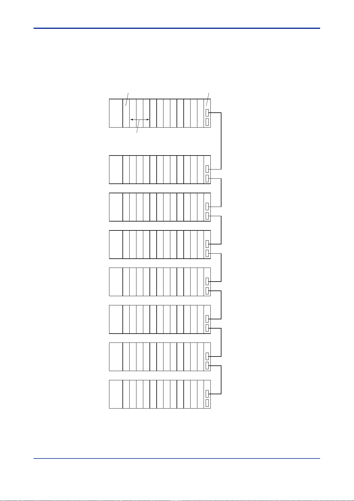
Example of Increasing the Number of I/O Points Using Fiber-optic
FA-bus 2 Modules
You can install fiber-optic FA-bus 2 modules in both main and subunits and connect
them with optical fiber cables. This enables distributed arrangement of remote I/O
points, increase in the number of I/O points, and control of I/O modules via high-speed,
noise-immune communication.
CPU module
Fiber-optic FA-bus 2 module
A1-2
FA-M3
main unit
Power
supply
module
add-on sequence CPU modules (up to three)
Subunit 1
Power
supply
module
Subunit 2
Power
supply
module
Subunit 3
Power
supply
module
Subunit 4
Power
supply
module
Example of I/O configuration (32 points)
224 points
(384 points without expansion module)
*
denotes a fiber-optic FA-bus 2 module.
Subunit 5
Power
supply
module
Subunit 6
Power
supply
module
Subunit 7
Power
supply
module
The maximum length of each optical fiber cablebetween units is 500m.
FA010103.VSD
Figure A1.3 I/O Expansion Using Fiber-optic FA-bus 2 Modules
- The maximum number of subunits that can be connected is 7.
Subunit numbers are determined depending on the setting of the rotary switch on
the fiber-optic FA-bus 2 module mounted to a subunit.
IM 34M6C11-01E 6th Edition : May 10, 2001-00
Page 16
A1.2 Restrictions on Installing Modules
A1.2.1 Restrictions on Module Location
- A CPU module installed in slot 1 serves as the main CPU module.
- CPU modules installed in slots 2 to 4 serve as the add-on CPU modules.
- I/O modules may also be installed in slots 2 to 4. No add-on sequence CPU module
or add-on BASIC CPU module can be installed in a slot with a slot number greater
than those of the I/O modules.
- In an application where two or more CPU modules are installed, no I/O module can
be installed between any two CPU modules.
A1-3
Slot
123456
No
I/O module
Main CPU module
Power supply module
Figure A1.4 Restrictions on Module Location
Add-on CPU module
'
' × '
''
I/O module
Slot
No
123456
Main CPU module
Power supply module
123456
I/O module
I/O module
Add-on CPU module
Power supply module
Unused
Main CPU module
I/O module
Add-on CPU module
FA010201.VSD
'
''
IM 34M6C11-01E 6th Edition : May 10, 2001-00
Page 17
A1.2.2 Restrictions on CPU Module Installation
A maximum of four CPU modules can be installed in slots 1 to 4.
Table A1.1 Combinations of Main CPU Modules with Add-on CPU Modules
Add-on CPU Module
Model
Maximum Qty.
F3SP21-0N
F3SP25-2N
F3SP35-5N
F3SP28-3N
F3SP38-6N
F3SP53-4H
F3SP58-6H
F3BP20-0N
F3SP21-0N 4 ''''''''''
F3SP25-2N 4 ''''''''''
F3SP35-5N 4 ''''''''''
F3SP28-3N 4 ''''''''''
F3SP38-6N 4 ''''''''''
F3SP53-4H 4 ''''''''''
F3SP58-6H 4 ''''''''''
Main CPU Module
F3BP20-0N 1 '''''''–– '
F3BP30-0N 1 '''''''–– '
F3FP36-3N 1 ''''''''' –
F3BP30-0N
A1-4
F3FP36-3N
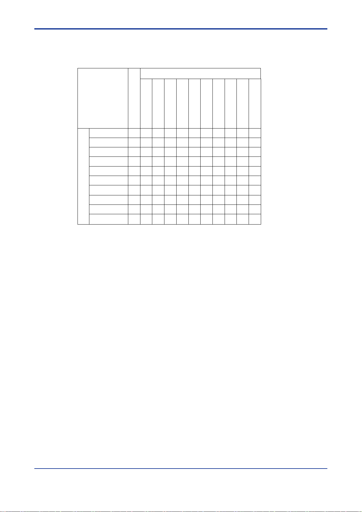
A1.2.3 Restrictions on I/O Module Installation
Table A1.2 shows the types of modules that each CPU module can access directly, as
well as the maximum number of modules of each type that can be installed at the same
time. The maximum number referred to here means a limit to the quantity of modules
when a multiple of the same I/O module is installed.
-“
'’’ identifies an I/O module that can be installed without limitation on its quantity.
– ’’identifies an I/O module to which the CPU module in question cannot have
-“
direct access.
- Each numeral means the maximum number of I/O modules that can be installed,
provided that they are of the same type.
In addition to the restrictions on the quantity of each I/O module, there are system-wide
limitations to the quantity of I/O modules that can be installed. For more information,
see Appendix A1, “System-wide Restrictions on Module Installation.”
IM 34M6C11-01E 6th Edition : May 10, 2001-00
Page 18

Table A1.2 Modules that Each CPU can Access Directly and the Maximum Number
-VN
-
3N1616161616161
-
0
-
6
-
6
-VF
-
3
-VF
6
-VN
-VN
6
-VV326
6
6
-
2
-0C
-
0
-
0
-
7
-
6
-
5
-
1V6
-
1V326
6
6
-VF
326
6
6
-VN
326
6
6
-
0N3636363636363
-
1N3636363636363
-
0N3636363636363
-
1N3636363636363
-
5N3636363636363
-VN
2828282828282
-VN
2828282828282
-
1N2828282828282
-
0N3236363636363
-1F
-
1
-
2
2-1
-
2N4444444
-
0N1616161616161
-
5T2*16*16*16*16*16*16
-
0
*
8888888
-
0N–––––––
-
0N–––––––
-
0N3236363636363
-
0N3236363636363
that can be Installed (1 of 4)
Sequence CPU BASIC CPU
Module Name Model
A1-5
F3XA08
F3XH04
F3XC08
F3XD08
F3XD08
Inputmodule
F3XD16
F3XD16
F3XD32
F3XD16
F3XD32
F3XD64
F3YA08
F3YC08
F3YC08
F3YC16
Outputmodule
F3YD04
F3YD08
F3YD14
F3YD32
F3YD64
I/Omodule
Analog input module
F3WD64
F3WD64
F3AD04
F3AD08
F3DA02
Analog outputmodule
F3DA04
F3DA08
Temperaturecontroland monitoring
module
F3CT04
F3CR04
PID controlmodule F3CV04
Discontinuitydetection module F3HB08
F3LC11
Personalcomputerlinkmodule
UT linkmodule
*9
F3LC11
F3LC11
F3LC1
F3LC51
DeviceNetinterfacemodule F3LD01
Ethernetinterfacemodule F3LE01
GP-IBcommunicationmodule
F3GB01
RS-232-Ccommunicationmodule F3RS22
RS-422-Acommunicationmodule F3RS41
Ladder communicationmodule
F3RZ81
F3RZ91
F3SP21-0N
F3SP25-2N
F3SP35-5N
F3SP28-3N
F3SP38-6N
F3SP53-4H
F3SP58-6H
F3FP36-3N
'''''''' ' '
61616*216
'''''''' ' '
N
'''''''' ' '
F
'''''''' ' '
N
'''''''' ' '
'''''''' ' '
H
''''''' ' '
4
'''''''' ' '
''''''' ' '
4
'
4
'''''''' ' '
N
'
4
'
4
64
'''''''' ' '
'''''''' ' '
N
'''''''' ' '
N
'''''''' ' '
N
'''''''' ' '
V
'''''''' ' '
V
''''''' ' '
4
'
4
'
4
'
4
'
4
'
4
'
4
'
4
4
4
64
'
64
'
64
636 36 36
636 36 36
636 36 36
636 36 36
636 36 36
828 28 28
828 28 28
828 28 28
636 36 36
N
*16*16*16*16*16*16*16*16*1
2
N
F
44 4
616 16 16
*16*16*1
7
N
88 8
–3636
–3636
636 – –
636 – –
F3BP20-0N
F3BP30-0N
*2
''
''
''
''
*1
6
*1
6
IM 34M6C11-01E 6th Edition : May 10, 2001-00
Page 19

Table A1.2 Modules That Each CPU Can Access Directlyand the Maximum Number
*
*
of Them That Can Be Installed (1 of 4)
Sequence CPU BASIC CPU
Module Name Model
A1-6
F3SP58-6H
8*38
10
*5
'
'
7
64
64
*3
*6
*5
*6
F3FP36-3N
F3BP20-0N
F3BP30-0N
––
––
*57*5
7
''
''
FA link H module F3LP02-0N
Fiber-optic FA link H module F3LP12-0N
Fiber-optic FA-bus module F3LR01-0N
Fiber-optic FA-bus 2 module F3LR02-0N
High-speedcountermodule
F3XP01-0H 32 64
F3XP02-0H 32 64
F3SP21-0N
F3SP25-2N
F3SP35-5N
F3SP28-3N
F3SP38-6N
2*38*38*38*38*38
*6
*6
*6 *6
7*57*57
*6
*10
*6 *4
*5
'
'
*10
7*57*57*57
'
64
'
64
64
64
*3
10
F3SP53-4H
Pulseinputmodule F3XS04-VN3236363636363636 36 36
F3YP04-0N 32 36 36 36 36 36 36 36 36 36Positioningmodule
(Modelwithmultichannelpulse
output)
Positioningmodule
(Advancedmodelwithpositioning
pulseoutput)
F3YP08-0N 32 36 36 36 36 36 36 36 36 36
F3NC11-0N 32 36 36 36 36 36 36 36 36 36
F3NC12-0N 32 36 36 36 36 36 36 36 36 36
F3NC51-0N 32 36 36 36 36 36 36 36 36 36Positioning module
(Modelwithspeed-controlvoltage
output)
Install modules whose module names and models are shaded in main units.
*1: Each numeral means the total sum of personal computer link modules, Ethernet interface modules and GP-IB
communication modules (when in slave mode) that can be installed in combination. If two or more CPU modules
having different total sums of modules are installed, the smallest total sum takes precedence over the others.
*2: The pulse-capture feature is disabled.
*3: Each numeral means the total sum of FA link H modules and fiber-optic FA link H modules that can be installed in
combination. If two or more CPU modules having different total sums of modulesare installed, the smallest totalsum
takes precedence over the others.
*4: Configure the module using the WideField or Ladder Diagram Support Program M3.
*5: Each numeral means the total sum of the fiber-optic FA-bus and fiber-optic FA-bus2 modules that can be installed in
the main unit. If two or more CPU modules having different total sums of modules are installed, the smallest total
sum takes precedence over the others. If subunits are divided into groups using fiber-optic FA-bus 2 modules, the
total sum may become larger than this depending onthe mode of such division. For more information, see the Fiber-
optic FA-bus Module and Fiber-optic FA-bus Type 2 Module instruction manual (IM 34M6H45-01E).
*6: FA link H, fiber-optic FAlink H, and fiber-optic FA-bus 2 modules can be used with a sequence CPU module with
version 8 or later. For information on the version of a sequence CPU module, refer to the indication on its side.
*7: The maximum number that can be installed differs depending on the operating mode. The left number in each field
is when the module is in the master mode, while the right number (or symbol) is when the module is in the slave
mode.
F3NC52-0N 32 36 36 36 36 36 36 36 36 36
A1.2.4 Restrictions due to Current Consumption
Design your system making sure that the total sum of current consumed by modules in
each unit does not exceed the capacity of the power supply module.
For more information, see Section A2.8, “Tables of Modules’ Current Consumption.”
IM 34M6C11-01E 6th Edition : May 10, 2001-00
Page 20
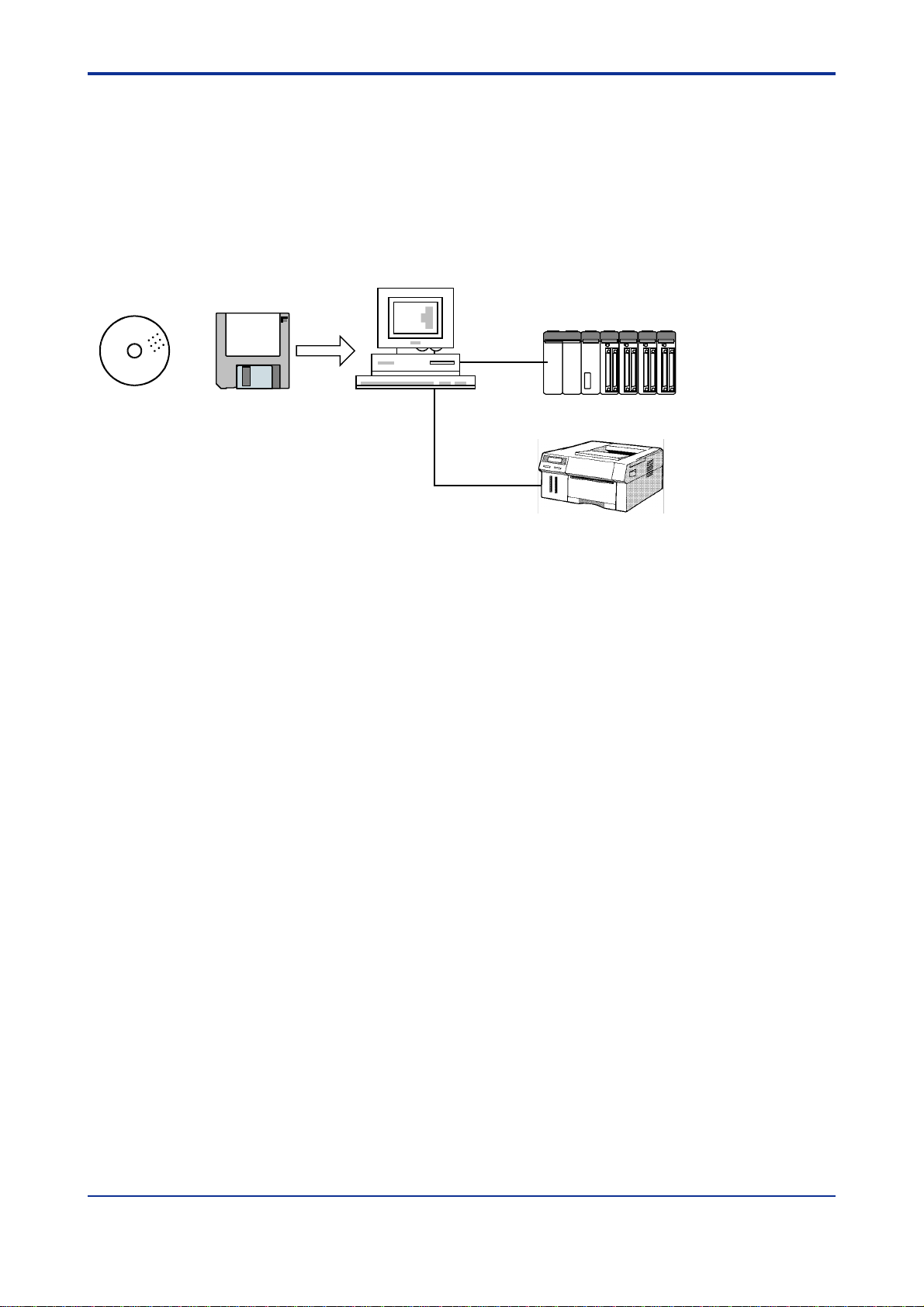
A1.3 Peripheral Tools Supporting the Program
Development of the FA-M3
You can conveniently create and debug your programs on your personal computer.
- FA-M3Programming Tool WideField
- LadderDiagram Support Program M3
- BASICProgramming Tool M3 for Windows
- Sequence Programming Tool for Windows POPMUSCAT
FA-M3
A1-7
CD-ROM
Floppy disk
Figure A1.5 Support Tools for the FA-M3
Personal
computer
Enternet or cable for programming tools
(RS-232-C)
Printer
FA010301.VSD
IM 34M6C11-01E 6th Edition : May 10, 2001-00
Page 21

Blank Page
Page 22

A2. Specifications and Configuration
A2.1 Specifications
Common Specifications
A2-1
Item
Supplyvoltagerange 100 to 240 V AC, singlephase 50/60 Hz 24 V DC
Range of supplyvoltagechange 85 to 264 V AC 50/60Hz±3Hz 15.6 to 31.2 V DC
Power consumption 35 VA 85 VA 15.4 W 33.1W
Insulation resistance
Withstandingvoltage
FAIL-signal contact output
Allowablecommonmode voltageofFAILsignalcontact
Leakagecurrent 3.5 mAmax.
Allowablemomentarypowerfailuretime 20 ms
Noiseimmunity
Vibrationresistance
Shockresistance
Operatingambienttemperaturerange 0˚Cto 55˚C
Operatingambienthumidityrange 10 to 90% RH (non-condensing)
Operatingenvironment Mustbe free of corrosivegases, flammable gases or heavy dust.
Storgeambienttemperaturerange -20˚Cto75˚C
Storageambienthumidityrange 10 to 90% RH (non-condensing)
Grounding JISClass3grounding
Coolingmethod Natural-aircooled
Mounting DirectmountingwithM4-size setscrews*1or DIN-railmounting(exceptfor F3BU16-0N module)
Structure Designedformountinginsideapanelenclosure
Altitudeofinstallation Max.of2000 m above sea level
Safety
and EMC
standards
Finish color
Externaldimensions See thedimensional figures in SectionA2.10,“ExternalDimensions.”
*2
*1: For details on the number of mounting screws, see subsection A3.2.1.
*2: For details on conforming modules, see “UL-certified and CE Mark-compliant Modules” (GS 34M6C11-21E) general
*3: The term installation category involves prescriptions on resistance to surge voltage reduction due to lightning and has four
*4: The term pollution degree is related to the degree of contamination with solid, liquid or gaseous substance that may produce a
EMC
specification brochure.
categories. Installation category II applies to systems with rated voltage of 220/230/260V and applies to electrical
appliances, portable devices, etc.
reduction of dielectric strength or surface resistivity in the operating environment of the equipment. Pollution degree 2normally
refers to environment contaminated only with dry, non-conductive electrical substance. However ,whencondensation
sometimes occurs, temporary conduction may occur.An environment which is contaminated only withelectrical substance
which are normally dry and non-conductive, but which may become temporarily conductive under occasional conditions of
condensation.
F3PU10-0N F3PU20-0N F3PU16-0N F3PU26-0N
5MΩ min. when tested between a group of external
AC terminalsandthe FG terminalusinga 500 VDC
insulationresistance tester
1500 VACforone minute between a groupofexternal
AC terminalsandthe FG terminal
Locatedonthefrontterminal blockofpowersupplymodule; contactratings:24 V DC, 0.3A (Equippedwithboth
normally-openand normally-closed terminals)
120 VACor DC max.
(betweenthe COM terminalof FAILOUTPUT and the FGterminal)
Tested using a noise simulator with a noise voltageof 1500 Vp-p, pulse width of 1 µs, rise time of 1 ns, and
repetitionfrequency of 25 to 60 Hz.
For CE Marking-compliantmodules, compliant to EN61326-1 and EN61000-6-2
Tested in compliance with JIS C0911underthefollowingconditions:
- Frequencyranges: 10 to 55 Hz withan amplitude of 0.15 mm
- Directionandfrequencyof sweep: 10 timeseach in the X, Y,and Zdirections
(one octaveforoneminute)
Tested in compliance with JIS C0912 under the following conditions:
- Directionandfrequencyof sweep: 3 timeseachinthe X, Y,and Z directionswithanaccelerati onof 98 m/s
UL508-approved(FileNo.E188707)
ComplianttoIEC1010-1and EN61010-1
(CategoryIIInstallation
EMI : ComplianttoEN61326 and EN55011,Group1,ClassA
EMS : ComplianttoEN 61326 and EN 61000-6-2
Power supplyharmonicwave:Compliant to EN 61000-3-2
Flicker : Compliant to EN 61000-3-3
Lightcobaltblue,equivalentto Munsell 6.2PB 4.6/8.8;
Lampblack,equivalentto Munsell 0.8Y 2.5/0.4
*3
and PollutionDegree*42)Compliancewithsafety
Specifications
5MΩ min. when tested acrossa groupofexternalDC
terminalsand theFGterminalusing a 500VDC
insulationresistance tester
1500 VACforone minute between a group of
externalDCterminalsand theFG terminal
55 to 150 Hz with an acceleration of 9.8 m/s2(1 G)
2
(10 G)
IM 34M6C11-01E 6th Edition : May 10, 2001-00
Page 23
A2.2 FA-M3 Controller Configuration
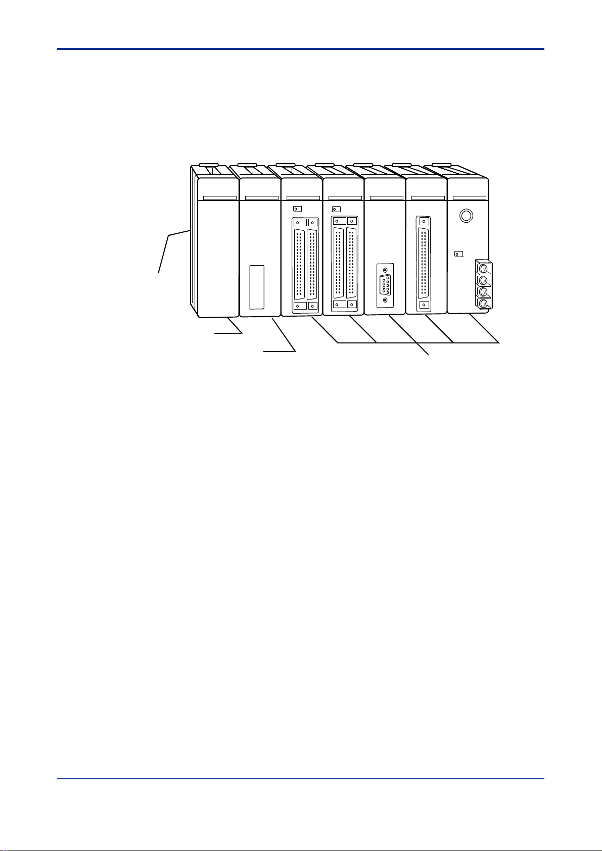
A2.2.1 Components
Module Names
Base module
Power supply module
A2-2
CPU module
Figure A2.1 FA-M3 Controller
I/O modules and
special modules
FA020201.VSD
IM 34M6C11-01E 6th Edition : May 10, 2001-00
Page 24
FA-M3 Components
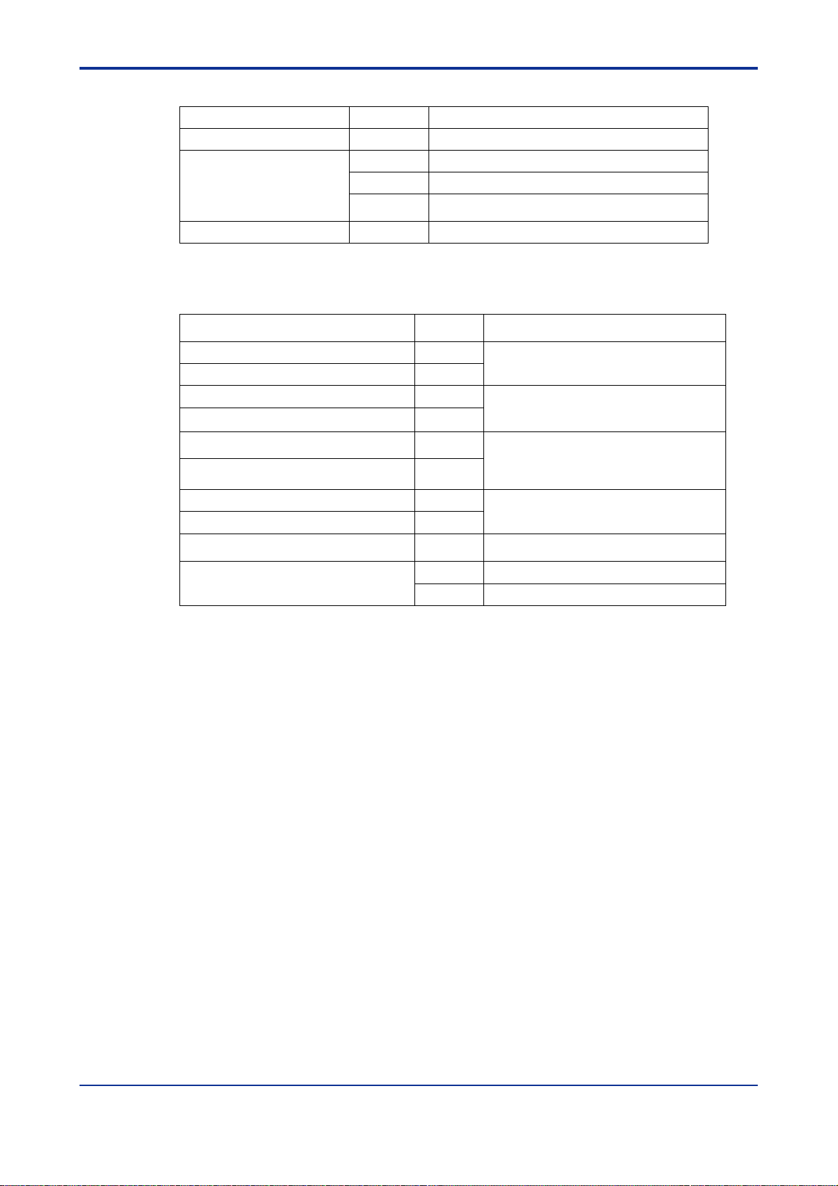
Base Modules
Module Description Model Specifications
Base module
Power Supply Modules
Module Description Model Specifications
Power supply module
F3BU04-0N
F3BU06-0N
F3BU09-0N
F3BU13-0N
F3BU16-0N
F3PU10-0N 100 to 240 VAC, for F3BU04 and F3BU06
F3PU16-0N 24 V DC, for F3BU04 and F3BU06
F3PU20-0N 100-240 V AC, for F3BU09, F3BU13 and F3BU16
F3PU26-0N 24 V DC, for F3BU09, F3BU13 and F3BU16
Slot for F3PU10/16 power supply module plus 4
slots (for CPU and I/O modules)
Slot for F3PU10/16 power supply module plus 6
slots (for CPU and I/O modules)
Slot for F3PU20/26 power supply module plus 9
slots (for CPU and I/O modules)
Slot for F3PU20/26 power supply module plus 13
slots (for CPU and I/O modules)
Slot for F3PU20/26 power supply module plus 16
slots (for CPU and I/O modules)
A2-3
NEW
CPU Modules
Module Description Model Specifications
Sequence CPU module
(with memory)
BASIC CPU module
ROM Packs
Module Description Model Specifications
ROM pack
F3SP21-0N
F3SP25-2N
F3SP35-5N
F3SP28-3N
F3SP38-6N
F3SP53-4H
F3SP58-6H
F3FP36-3N
F3BP20-0N 120 KB for BASIC
F3BP30-0N 510 KB for BASIC
RK10-0N 5K ladder steps (F3SP21/30)
RK30-0N
RK50-0N
RK33-0N 56K ladder steps (F3SP21/25/28/35/38/53/58)
RK53-0N
RK73-0N 120K ladder steps, (F3SP28/38/53/58)
10K ladder steps, with 0.18 to 0.36 µsexecution
time for basic instructions
20K ladder steps, with 0.12 to 0.24 µsexecution
time for basic instructions
100K ladder steps, with 0.09 to 0.18 µsexecution
time for basic instructions
30K ladder steps, with 0.045 to 0.18 µsexecution
time for basic instructions
120K ladder steps, with 0.045 to 0.18 µs
execution time for basic instructions
56K ladder steps, with 0.0175 to 0.07 µs
execution time for basic instructions
120K ladder steps, with 0.0175 to 0.07µs
execution time for basic instructions
For SFC/ladder language; 40K ladder steps
Contact coil 0.09µs per instruction
20K ladder steps; 120KB for BASIC
(F3SP21/25/30/35, F3BP20)
100K ladder steps; 510KB for BASIC
(F3SP21/25/35, F3BP30)
100K ladder steps; 510KB for BASIC
F3SP21/25/35, F3BP30)
NEW
NEW
NEW
NEW
NEW
NEW
NEW
IM 34M6C11-01E 6th Edition : May 10, 2001-00
Page 25
A2-4
I/O Modules
Module Description Model Specifications
High-speed input module F3XH04-3N 24VDChigh-speedinput points with pulse-capture feature, 4points
AC input module
DC input module
Voltage-free contact input
module
Triac output module F3YA08-2N Triac output (100 to 240 V AC), 2 A, 8 points
Relay output module
Transistor output module
I/O module
*1: Input response of 100 µs or more can be set when F3SP28, F3SP38, F3SP53 or F3SP58 module is used.
*2: Theoutput HOLD/RESET for a fatal failure of a CPU can be set whenF3SP28, F3SP38, F3SP53 or F3SP58 module is used.
F3XA08-1N 100 to 120 VAC, 8 points
F3XA08-2N 200 to 240 VAC, 8 points
F3XD08-6F DC Input sink/source, 12 to 24 V DC, 8 points
F3XD16-3F DC Input sink/source, 24 V DC, 16 points
F3XD16-4F DC Input sink/source, 12 V DC, 16 points
F3XD16-3H
DC Input sink (positive common), 24 V DC, 16 points
(High speed input)
F3XD32-3F DC Input sink/source, 24 V DC, 32 points
F3XD32-4F DC Input sink/source, 12 V DC, 32 points
F3XD32-5F DC Input sink/source, 5 V DC, 32 points
F3XD64-3F DC Input sink/source, 24 V DC, 64 points
F3XD64-4F DC Input sink/source, 12 V DC, 64 points
*1
*1
*1
*1
*1
*1
*1
*1
F3XD08-6N DC input sink/ source, 12 to 24 V DC, 8 points
F3XD16-3N DC Input sink/source, 24 V DC, 16 points
F3XD16-4N DC Input sink/source, 12 V DC, 16 points
F3XD32-3N DC Input sink/source, 24 V DC, 32 points
F3XD32-4N DC Input sink/source, 12 V DC, 32 points
F3XD32-5N DC Input sink/source, 5 V DC, 32 points
F3XD64-3N DC Input sink/source, 24 V DC, 64 points
F3XD64-4N DC Input sink/source, 12 V DC, 64 points
F3XD64-6M DC Input matrix scan, 12 to 24 V DC, 64 points
F3XC08-0N No-voltage contact input, 8 points
F3YC08-0C
Relay output (24 V DC, 100 to 240 V AC), 2 A, 8 points, all
independent
F3YC08-0N Relay output (24 V DC, 100 to 240 V AC), 2 A, 8 points
F3YC16-0N Relay output (24 V DC, 100 to 240 V AC), 2 A, 16 points
F3YD04-7N TR output, 24 V DC, 2A, all independent, 4 points
F3YD08-6A TR output sink type, 12 to 24 V DC, 1A, 8 points
F3YD08-6B TR output source type, 12 to 24 V DC, 1A, 8 points
F3YD14-5A TR output sink type, 12 to 24 V DC, 0.5A, 14 points
F3YD14-5B TR output source type, 12 to 24 V DC, 0.5A, 14 points
F3YD32-1A TR output sink type, 12 to 24 V DC, 0.1A, 32 points
F3YD32-1B TR output souece type, 12 to 24 V DC, 0.1 A, 32 points
F3YD32-1T TTL output, 5 V DC, 16 mA, 32 points
F3YD64-1F TR output sink type, 24 V DC, 0.1A, 64 points
*2
F3YD64-1A TR output sink type, 24 V DC, 0.1 A, 64 points
F3YD64-1M TR output matrix scan, 12 to 24 V DC, 0.1A, 64 points ( 8 x 8 )
F3WD64-3F
F3WD64-4F
F3WD64-3N
F3WD64-4N
DC Input sink/source, 24 V DC, 32 points
TR Output sink type, 24 V DC, 0.1A, 32 points
DC Input sink/source, 12 V DC, 32 points
TR Output sink type, 12 V DC, 0.1A, 32 points
DC Input sink/source, 24 V DC, 32 points
TR Output sink type, 24 V DC, 0.1A, 32 points
DC Input sink/source, 12 V DC, 32 points
TR Output sink type, 12 V DC, 0.1A, 32 points
*1
*2
*1
*2
*1
NEW
NEW
NEW
NEW
NEW
NEW
NEW
NEW
NEW
NEW
NEW
NEW
NEW
IM 34M6C11-01E 6th Edition : May 10, 2001-00
Page 26

A2-5
Analog I/O and Temperature Control Modules
Module Description Model Specifications
Analog input module
Analog output module
Temperature
control/monitoring module
PID control module F3CV04-1N DC-voltage input, 0.5 second scan, 4 loops
Communication Modules
Module Description Model Specifications
Personal computer link
module
UT link module F3LC51-2N
DeviceNet interface module F3LD01-0N
Ethernet interface module F3LE01-5T 10Mbps, 10BASE5/10BASE-T
RS-232-C communication
module
RS-422 communication
module
Ladder communication
module
GP-IB communication
module
F3AD04-0N 0 to 5/1 to 5/-10 to 10 V DC input, 4 points
F3AD08-1N 0 to 5/1 to 5/-10 to 10 V DC input, 8 points
F3DA02-0N –10 to 10 V/4 to 20 mA DC output, 2 points
F3DA04-1N –10 to 10 V/4 to 20 mA DC output, 4 points
F3DA08-5N –10 to 10 V DC output, 8 points
F3CT04-0N
F3CT04-1N
F3CR04-0N RTD input, 0.5 second scan, 4 loops
F3CR04-1N
F3LC11-1F 1 RS-232-C port; 115.2 kbps max.
F3LC11-1N 1 RS-232C port; 19200 bps max.
F3LC11-2N 1 RS-422-A/RS-485 port; 19200 bps max.
F3LC12-1F 2 RS-232-C ports; 115.2 kbps max.
F3RS22-0N 2 RS-232-C ports; 19200 bps max.
F3RS41-0N 1 RS-422-A/RS-485 port; 19200 bps max.
F3RZ81-0N 1 RS-232-C port; 19200 bps max.
F3RZ91-0N 1 RS-422/RS-485 port; 19200 bps max.
F3GB01-0N 1 GP-IB communication port
Thermocouple or mV input, 0.5 second scan, 4
loops
Thermocouple or mV input, 0.5 second scan, 4 to
20 mADC output, 4 loops
RTD input, 0.5 second scan, 4 to 20 mA DC
output, 4 loops
1 RS-422-A/RS-485 port of 38400bps max. for
easy connection with a temperature controller
1 DeviceNet port of 500 kpps max., with
master/scanner functions
NEW
NEW
FA Link and Fiber-optic FA-bus Modules
Module Description Model Specifications
FAlink H module F3LP02-0N
Fiber-optic FAlink H module F3LP12-0N
Fiber-optic FA-bus module F3LR01-0N
Fiber-optic FA-bus 2 module F3LR02-0N
Up to 32 stations with a transmission distance
of 1 km max., 1.25 Mbps
Up to 32 stations with an extensive distance
of 10 km max., 1.25 Mbps
Up to 6 stations with a base-to-base distance
of 200 m max., 10 Mbps
Up to 32 stations with an extensive distance
of 1.4 km max., 10 Mbps
IM 34M6C11-01E 6th Edition : May 10, 2001-00
Page 27
Counter and Positioning Modules
Module Description Model Specifications
High-speed counter module
Pulse input module
Positioning module
(Advanced model with
positioning pulse output)
Positioning module
(Model with speed-control
voltage output)
Positioning module
(Model with multichannel
pulse output)
F3XP01-0H 100 kpps, 1 channel, 32 bits
F3XP02-0H 100 kpps, 2 channels, 32 bits
F3XS04-3N 20 kHz, 4 channels, 24 V input, 16 bits
F3XS04-4N 20 kHz, 4 channels, 12 V input, 16 bits
F3NC11-0N
F3NC12-0N
F3NC51-0N
F3NC52-0N
F3YP04-0N
F3YP08-0N
1-axis position and speed control with a max.
speed of 250 kbps
2-axis position and speed control with a max.
speed of 250 kbps
1-axis position and speed control with a max.
speed of 2M pps
1-axis position and speed control with a max.
speed of 2M pps
4-axis position control with a max. speed of
250000 pps
8-axis position control with a max. speed of
250000 pps
A2-6
IM 34M6C11-01E 6th Edition : May 10, 2001-00
Page 28

Cables
A2-7
Cable Description Model
Cable for programming
tools
CPU port/9-pin D-sub
adapter cable
Fiber-optic cord
*3 *4
for
wiring inside panel
enclosure (compatible
with F3LR01, F3LR02 and
F3LP12)
Fiber-optic cable
*3 *4
for
indoor wiring, supplied
with tension member
(compatible with F3LR01,
F3LR02 and F3LP12)
Fiber-optic cable
*3 *4
for
outdoor wiring, supplied
with tension member
(compatible with
F3LR01 [up to 200 m],
F3LR02 [up to 200 m],
and
F3LP12 [up to 1000 m])
Fiber-optic cable*3for
outdoor wiring, supplied
with tension member
(compatible with F3LR02
(200 to 500 m))
Cable for connector
terminal blocks
*2
Style
Code
KM11-2T *A D-sub, 9-pin, male, 3 m long
KM11-3T *A D-sub, 9-pin, male, 5 m long
KM11-4T *A D-sub, 9-pin, male, 10 m long
Specifications
*1
*1
*1
KM10-0C ― D-sub, 9-pin, female, approx. 0.5 m long
KM60-S06 ― Cord for system expansion inside panel enclosure; 0.6 m long
KM60-001 ― Cord for system expansion inside panel enclosure; 1 m long
KM60-003 ― Cord for system expansion inside panel enclosure; 3 m long
KM61-010 ― Cable for indoor system expansion; 10 m long
KM61-100 ―
KM61-150 ―
KM61-200 ―
KM62-100 ―
KM62-200 ―
KM62-300 ―
KM62-400 ―
KM62-500 ―
KM62-600 ―
KM62-700 ―
KM62-800 ―
KM62-900 ―
KM62-L01 ―
KM67-300 ―
KM67-400 ―
KM67-500 ―
Cable for indoor system expansion; 100 m long
(supplied with one pulling eye)
Cable for indoor system expansion; 150 m long
(supplied with one pulling eye)
Cable for indoor system expansion; 200 m long
(supplied with one pulling eye)
Cable for outdoor system expansion; 100 m long
(supplied with one pulling eye)
Cable for outdoor system expansion; 200 m long
(supplied with one pulling eye)
Cable for outdoor system expansion; 300 m long
(supplied with one pulling eye)
Cable for outdoor system expansion; 400 m long
(supplied with one pulling eye)
Cable for outdoor system expansion; 500 m long
(supplied with one pulling eye)
Cable for outdoor system expansion; 600 m long
(supplied with one pulling eye)
Cable for outdoor system expansion; 700 m long
(supplied with one pulling eye)
Cable for outdoor system expansion; 800 m long
(supplied with one pulling eye)
Cable for outdoor system expansion; 900 m long
(supplied with one pulling eye)
Cable for outdoor system expansion; 1000 m long
(supplied with one pulling eye)
Cable for outdoor system expansion; 300 m long
(supplied with one pulling eye)
Cable for outdoor system expansion; 400 m long
(supplied with one pulling eye)
Cable for outdoor system expansion; 500 m long
(supplied with one pulling eye)
KM55-005 ― For connection between module and connector terminal block; 0.5 m long
KM55-010 ― For connection between module and connector terminal block; 1 m long
KM55-015 ― For connection between module and connector terminal block; 1.5 m long
KM55-020 ― For connection between module and connector terminal block; 2 m long
KM55-025 ― For connection between module and connector terminal block; 2.5 m long
KM55-030 ― For connection between module and connector terminal block; 3 m long
*1 : Supports DOS/V.
*2 : Cannot be used with F3YP04 and F3YP08 since they use 48-pin connectors.
*3 : For details, see “Fiber-optic FA-bus Module and Fiber-optic FA-bus Type 2 Module” Manual (IM34M6H45-01E).
*4 : For details, see “FALink H Module and Fiber-optic FALink H Module” Manual (IM34M6H43-01E).
IM 34M6C11-01E 6th Edition : May 10, 2001-00
Page 29
Spare Parts
Module Description Model Specifications
Terminal block unit* TA40-0N 40 points; voltage rating: 5 to 24 V DC
TA50-0N Connector terminal block 40 points (M3.5 screw)
Connector terminal block*
Blank module F3BL00-0N For empty I/O slots
* : Cannot be used with F3YP04 and F3YP08 modules since they use 48-pin connectors
Accessory
TA50-1N Connector terminal block 40 points (M3 screw)
TA60-0N
Connector terminal block 40 points (Europe
terminal type)
A2-8
Description
Terminal for 10-point terminal block A1474JT
Terminal cover for 10-point terminal block A1472JT
Terminal for 18-point terminal block A1496JT
Terminal cover for 18-point terminal block A1494JT
Soldered connector (40-pin plug) A1451JD
Cover for connector (40-pin plug) A1452JD
Soldered connector (48-pin plug) A1612JD
Cover for connector (48-pin plug) - 2units A1613JD
Dustproof connector cover - 20 units T9031AS
Rail-mounting kit
* : Not supplied with the product
Part
Number
T9031AP*F3BU04, F3BU06
T9031AQ
Applicable Module
F3XH04, F3XA08, F3XD08,
F3YD04, F3YA08, F3YC08-0N,
F3YD08, F3AD04, F3DA02
F3XD16, F3YD14, F3YC08-0C, F3YC16,
F3CR04, F3CV04, F3AD08, F3DA04,
F3DA08,F3XS04, F3HB08
*
F3XD32, F3XD64, F3WD64,
F3XP01, F3XP02
*
F3YD32, F3YD64, F3NC01, F3NC02
F3NC11, F3NC12, F3NC51, F3NC52
*
F3YP04, F3YP08
*
F3BU04, F3BU06, F3BU09, F3BU13,
F3BU16
*
F3BU09, F3BU13
IM 34M6C11-01E 6th Edition : May 10, 2001-00
Page 30

A2.3 Power Supply Modules
F3PU10-0N/F3PU20-0N Power Supply Modules
Specifications
A2-9
Item
Specifications
F3PU10-0N F3PU20-0N
Supply voltage range 100 to 240 V AC, single phase 50/60 Hz
Range of supply voltage
change
85 to 264 V AC 50/60 Hz±3 Hz
Power consumption 35VA 85VA
Inrush current
Fuse
1 A time-lag fuse
(Built into the L and N terminals
and cannot be replaced.)
20 A max. (120 V AC, Ta=25°C)
45 A max. (240 V AC, Ta=25°C)
2 A time-lag fuse
(Built into the L and N terminals and
cannot be replaced.)
Rated output voltage 5 V DC
Rated output current 2.0A 4.3 A
Insulation resistance
Withstanding voltage
5MΩ min. when tested between a group of externalAC terminals and
the FG terminal using a 500 VDC insulation resistance tester
1500 VAC for one minute
between a group of external AC terminals and the FG terminal
Leakage current 3.5 mA max
Allowable momentary power
failure time
External dimensions 28.9(W) × 100(H) × 83.2(D)mm
20 ms
*
58 (W) × 100 (H) ×83.2 (D) mm
Weight 190 gf 320 gf
Applicable base module
*: Excluding protrusions (see the dimensional figures for more information)
Dedicated to
F3BU04 and F3BU06
F3BU09, F3BU13 and F3BU16
Dedicated to
*
Components and Their Functions
The figure below shows the power supply modules with their covers removed.
F3PU10-0N F3PU20-0N
RDY
PU 10-0N POWER
FAIL
OUTPUT
FAIL1
COM
FAIL2
FG
LG
N
L
INPUT
100-240VAC
RDY indicator (green)
Across FAIL1 andCOM
Across FAIL2 andCOM
FG
LG
Power supply
`
Figure A2.2 F3PU10-0N and F3PU20-0N Power SupplyModules
Lit when the power
supply module is
normal.
FAIL signal contact output
Contact ratings: 24VDC, 0.3A
Normal operating
time
System Failure and
Power Failure Times
Open
Short
Subject to JIS class 3 grounding
independently
Connect to FG and grounded
100to240VAC
Short
Open
PU 20-0N
FAIL
OUTPUT
FAIL1
COM
FAIL2
FG
LG
N
L
INPUT
100-240VAC
RDY
`
POWER
FA020303.VSD
IM 34M6C11-01E 6th Edition : May 10, 2001-00
Page 31

DANGER
To avoid the hazard of possible electrical shock, turn off the power before removing the
cover for wiring or other purposes.
Terminal dimensions
M3.5
A2-10
7.1mm
Adaptable solderless terminal
Vendor Model Applicable Conductor Crimping Torque
Japan Solderless
Terminal Mfg Co., Ltd.
Nippon Tanshi Co., Ltd. RAV1.25-3.5
8.2mm
FA020304.VSD
V1.25-M3
AWG22 to 18 (0.33 to 0.82 mm
(Copper wire)
2
)
0.8N • m
CAUTION
When crimping terminals, be sure only to use the tool specified by each terminal
manufacturer.
Once the power supply module is installed in the base module, both the FG terminal of
the power supply module and the signal ground (GND terminal of the module’s 5 V
output) of the FA-M3 automatically come into contact with the metal chassis of the base
module. The FG terminal and the signal ground are isolated from each other inside the
power supply module.
For details on the grounding lines of the FA-M3, see subsection A3.3.2, “Grounding
Lines.”
IM 34M6C11-01E 6th Edition : May 10, 2001-00
Page 32

F3PU16-0N and F3PU26-0N Power Supply Modules
Specifications
A2-11
Item
Specifications
F3PU16-0N F3PU26-0N
Supply voltage 24 V DC
Range of supply voltage
change
15.6 to 31.2 V DC
Power consumption 15.4W 33.1W
nrush current 20 Amax. (31.2 V DC, Ta=25°C)
Fuse
3.15 A time-lag fuse
(Built into the positive and negative
terminals and cannot be replaced.)
(Built into the positive terminal and
5 A time-lag fuse
cannot be replaced.)
Rated output voltage 5 V DC
Rated output current 2.0 A 4.3 A
Insulation resistance
Withstanding voltage
Allowable momentary
power failure time
5MΩ min. when tested between a group of external DC terminals and the
FG terminal using a 500 VDC insulation resistance tester
1500 VAC for one minute between a group of external
DC terminals and the FG terminal
20 ms
External dimensions 28.9 (W) × 100 (H) × 83.2 (D) mm * 58 (W) × 100 (H) × 83.2 (D) mm *
Weight 190 gf 320 gf
Applicable base module
*: Excluding protrusions (see the dimensional figures for more information)
Components and Their Functions
Dedicated to
F3BU04 and F3BU06
F3BU09, F3BU13 and F3BU16
Dedicated to
The figure below shows the power supply modules with their covers removed.
F3PU16-0N
Lit when the power
supply module is normal.
FAIL signal contact output
Contact ratings: 24V DC, 0.3A
Normaloperating
time
Power Failure Times
Open
Short
Subject to JIS class 3 grounding
independently
Connected to FG and grounded
24V DC
System Failureand
Short
Open
PU 16-0N
FAIL
OUTPUT
FAIL1
COM
FAIL2
INPUT
24VDC
RDY
RDY indicator (green)
POWER
Across FAIL1 and COM
Across FAIL2 and COM
FG
FG
LG
-
+
LG
Power supply
Figure A2.3 F3PU16-0N and F3PU26-0N Power SupplyModules
DANGER
PU 26-0N
FAIL
OUTPUT
FAIL1
COM
FAIL2
INPUT
24VDC
F3PU26-0N
RDY
POWER
FG
LG
-
+
FA020305.VSD
To avoid the hazard of possible electrical shock, turn off the power before removing the
cover for wiring or other purposes.
IM 34M6C11-01E 6th Edition : May 10, 2001-00
Page 33

z
z Terminal dimensions
zz
M3.5
A2-12
7.1mm
z
z Adaptable crimp-on lugs
zz
Vendor Model Applicable Conductor Crimping Torque
Japan Solderless
Terminal Mfg Co., Ltd.
Nippon Tanshi Co., Ltd. RAV1.25-3.5
8.2mm
FA020306.VSD
V1.25-M3
AWG22to18
(0.33to0.82mm
(Copper wire)
2
)
0.8N⋅m
CAUTION
When crimping terminals, be sure only to use the tool specified by each terminal
manufacturer.
Once the power supply module is installed in the base module, both the FG terminal of
the power supply module and the signal ground (GND terminal of the module’s 5 V
output) of the FA-M3 automatically come into contact with the metal chassis of the base
module. The FG terminal and the signal ground are isolated from each other inside the
power supply module.
For details on the grounding lines of the FA-M3, see subsection A3.3.2, “Grounding
Lines.”
IM 34M6C11-01E 6th Edition : May 10, 2001-00
Page 34

A2.4 Base Modules
There are five types of base modules: 4 slot, 6 slot, 9 slot, 13 slot and 16 slot modules.
Select an appropriate type of module according to your application needs.
Model Number of Slots Number of I/O Slots Weight
F3BU04-0N 4 3 140 gf
F3BU06-0N 6 5 200 gf
F3BU09-0N 9 8 310 gf
F3BU13-0N 13 12 420 gf
F3BU16-0N 16 15 550 gf
A2-13
F0204.EPS
Figure A2.4 Base Modules
CAUTION
Once the power supply module is installed in the base module, both the FG terminal of
the power supply module and the signal ground (GND terminal of the module’s 5 V
output) of the FA-M3 automatically come into contact with the metal chassis of the base
module.
When any module having a SHIELD terminal is installed in the base module, the
SHIELD terminal automatically comes into contact with the metal chassis of the base
module.
Likewise, when any module having a D-sub or GP-IB connector is installed in the base
module, the connector’s metal shell automatically comes into contact with the metal
chassis of the base module.
For details on the grounding lines of the FA-M3, see subsection A3.3.2, “Grounding
Lines.”
IM 34M6C11-01E 6th Edition : May 10, 2001-00
Page 35

A2.5 I/O Modules
Components and Their Functions
Terminal Block Type
• 10-point terminal block • 18-point terminal block
13
9
5
XA08-
COM
1
5
2
6
3
7
4
8
AC
VV
VV
VVVV
1
2
3
4
5
6
7
8
IN
Input indicaton LED:
Indicate the on or off
status of each inputs.
Terminal block:
10- or 18-point
detachable terminal
block. The terminal
screws are M3.5 self-up
screws.
XD16-
COM1
COM2
1
14
10
6
2
15
11
7
3
16
12
8
4
VV
VV
VVVV
1
2
3
4
5
6
7
8
9
10
11
12
13
14
15
16
DC IN
Connector Type
29
25
21
17
13
9
5
1
6
2
7
3
8
4
XDVV-
12
10
11
12
VV
14
15
16
26
22
18
27
23
19
28
24
20
DISPLAY
30
31
32
DC IN
A2-14
Input indication LED:
Indicate the on or off
status of each input.
Display selector switch:
Selects the LEDs. Not
available for 32-point
modules.
40-pin connector(s) (1 or 2):
The 32-point and
F3XD64-6M modules are
equipped with only one
connector.
Figure A2.5 I/O Module Front View
External Dimensions
Display Selector
Switch
1
2
Contents of 1 to 32 input LEDs
Indicates the on/off state of input terminals 1 to 32.
Indicates the on/off state of input terminals 33 to 64.
FA020501.VSD
FA020502.VSD
Figure A2.6 I/O Module External Dimensions (F3XD64-3N)
IM 34M6C11-01E 6th Edition : May 10, 2001-00
Page 36

Isolation Methods
The internal circuit is isolated from the field using one of the following methods:
Photocoupler isolation : Withstands 1500 V AC for 1 minute.
Mechanical isolation : Withstands 1500 V AC for 1 minute.
Transformer isolation : Withstands 500 V AC for 1 minute.
Terminal Arrangement
A2-15
10-point
terminal block
1
2
3
4
5
6
7
8
9
10
18-point
terminal block
1
2
3
4
5
6
7
8
9
10
11
12
13
14
15
16
17
18
M3.5
Connector
based
32-point type
BA
20
20
19
19
18
18
17
17
16
16
15
15
14
14
13
13
12
12
11
11
10
10
9
9
8
8
7
7
6
6
5
5
4
4
3
3
2
2
1
1
Connector
based
64-point type
BA
12
20
20
19
19
18
18
17
17
16
16
15
15
14
14
13
13
12
12
11
11
10
10
9
8
7
6
5
4
3
2
1
M3.5
BA
20
20
19
19
18
18
17
17
16
16
15
15
14
14
13
13
12
12
11
11
10
10
9
8
7
6
5
4
3
2
1
9
9
8
8
7
7
6
6
5
5
4
4
3
3
2
2
1
1
7.1mm
Note:Viewed from the front side of the module.
External Connection
There are two ways of connecting an input/output module externally: through a terminal
block (10 or 18 points) and through a connector. See Section A3.6, “Wiring I/O
Modules,” for more details on wiring.
8.2mm
8.2mm
6.4mm
7.1mm
FA020503.VSD
IM 34M6C11-01E 6th Edition : May 10, 2001-00
Page 37

I/O Module Specifications
(1) F3XH04-3N High-speed Input Module
Item Specifications Item Specifications
Input type DC voltage
Number of points 4
Common line type 4 independent points
Insulation method
Photo-coupler
insulation
1500 VAC for one
minute between the
group of terminals for
Withstanding voltage
external connection
(excluding SHIELD)
and the internal
circuit
Rated input voltage 24 V DC
Operating voltage range 20.4 to 26.4 V DC
Rated input current
11.2 mA/point
(24 V DC)
Input impedance 2.1 kΩ
Operating
ON
voltage/
Current
Response
time
OFF
OFF→ON 50 µs max. External connection
ON→OF F 50 µs max. Weight 120 gf
Minimum input pulse
width
* : The pulse capture feature and the interrupt feature cannot be used together.
16 V DC min.
7.2 mAmin.
6.0 V DC max.
2.5 mAmax.
50 µs
Pulse-capture
features
Interrupt
features
*
*
Dissipating current 20 mA(5 V DC)
Input display LED (Lit when input is on)
Maximum ratio of inputs
turned on simultaneously
Selection Selected by DIP switches
Selection Selected by DIP switches
Set for each point using
Setting
Ladder Diagram Support
Program M3.
Input hold
time
The input signal is held
for 512 µs after detection
of an off-to-on transition.
10-point terminal block
with M3.5 screws
100%
A2-16
Front View
F3XH04-3N
1
2
3
4
XH04-3N
+
IN1
-
SHIELD
+
IN2
-
+
IN3
-
SHIELD
+
IN4
-
FA020504.VSD
DC IN
Internal Circuit Configuration
1
+
+
−
1-
External Connection Diagram
1
1
SHIELD
2
+
−
Note: Viewed from the front side of the module.
2
3
3
SHIELD
4
4
FA020506.VSD
Bus
Interface
+
1
−
2
3
+
4
−
5
+
6
−
7
8
+
9
−
10
Internal Bus
FA020505.VSD
IM 34M6C11-01E 6th Edition : May 10, 2001-00
Page 38

Setting up the Pulse-capture and Interrupt Functions
The F3XH04-3N allows you to enable the pulse-capture or interrupt function by setting
its internal DIP switch (DIP SW).
Hardware Setup
Remove the side cover and select the desired function with internal DIPSW 1.
The pulse-capture function is selected as default at the factory.
Side View of Module
A2-17
Front
Rear
1
O
2
F
3
F
4
Top
OFF ON
SW1
SW2
SW3
SW4
1
2
3
4
F3XH04 -3N Side View With Side Cover Removed
DIP SW No.
1
2
3
4
Figure A2.7 Setting the Pulse-capture/Interrupt Functions
Pulse-capture function
OFF
Interrupt function
Not used
Not used
Not used
ON
Not used
Not used
Not used
Bottom
Default
OFF
OFF
OFF
OFF
FA020507.VSD
IM 34M6C11-01E 6th Edition : May 10, 2001-00
Page 39

A2-18
Software Setting
You can use the pulse-capture function by specifying terminal numbers 17-20 in a ladder
program. There is no need to make special settings. Set the interrupt function for each
input point. In either case, make sure that the correct function is selected as explained
in the paragraph entitled “Hardware Setup.”
Accessing a Module
- Pulse-capture function
This function is available only through a ladder program. Inputs 1-4 correspond to
terminal numbers 17-20.
Xℓmm17-Xℓmm20 ℓ : Base unit number (0 to 7)
mm : Slot number
- Interrupt function
The interrupt function may be used from either a ladder or BASIC program.
Inputs 1-4 correspond to terminal numbers 1-4.
- Interrupt processing in a ladder program
When using the interrupt function as an interrupt input, make an “I/O interrupt
definition” using the INTP instruction.
You can perform I/O interrupt definitions for a maximum of 4 points per single CPU
module. When an interrupt input is presented from the F3XH04-3N, an interrupt
program that begins with an INTP instruction and ends with an IRETinstruction is
executed.
The interrupt response time, which is the tim e required for the CPU module to
recognize an interrupt input from the F3XH04-3N and startexecuting the interrupt
program, is dependant on the CPU module model and has the following
approximate values.
F3SP21 / 25 / 35 : approximately 0.5 ms
F3SP28 / 38 : approximately 120 μs
F3SP53 / 58 : approximately 100 μs
CAUTION
1. Do not perform "I/O Interrupt Def inition" for the same F3XH04-3N input module
from multiple CPU modules. The CPU module cannot be correctly notified of an
interrupt from the F3XH04-3N input module.
2. Define the following interrupt period as a standard:
- Interruptinput...onlyonepointdefinedperCPU 1msandabove
If the interrupt period is 1 to 2 ms, ensure that the scan time is 2 ms or longer.
If the scan time is less than 2 ms, use the constant scan time feature.
- Interruptinput...2to4pointsdefinedperCPU 10msandabove
If the interrupt period is short, the interrupt program will be executed frequently,
affecting normal program execution. It may also cause delay in responding to
commands from programming tool or personal computer link s.
IM 34M6C11-01E 6th Edition : May 10, 2001-00
Page 40

- Interrupt processing in a BASIC program
Declare the acceptance of interrupts with an ON INT statement after declaring the
use of a module with an ASSIGN statement.
For more information, see Section C4.3, “Interrupts,” in the BASIC CPU Modules
and YM-BASIC/FA Programming Language instruction manual (IM 34M6Q22-01E).
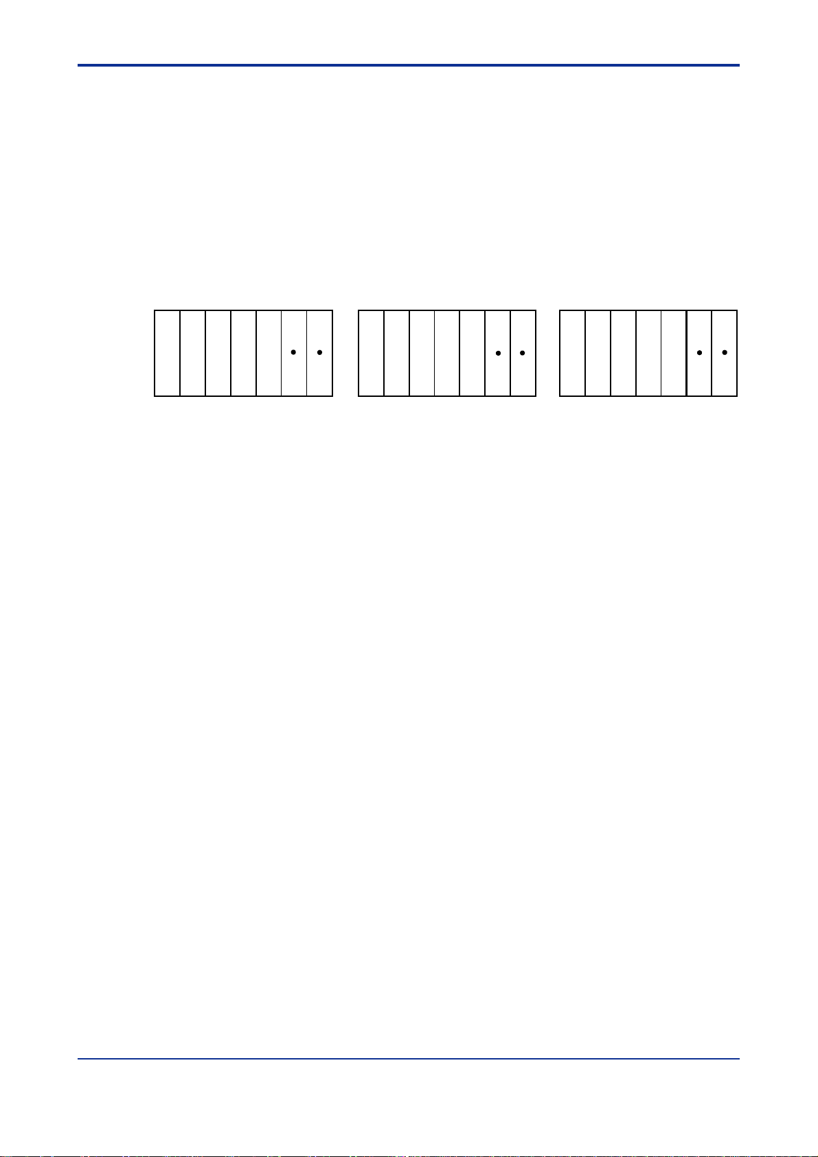
Functional Description
- Pulse-capture Function
The pulse-capture function is designed to reliably catch input pulses shorter than the
scan time.
Since CPU modules usually read the data of I/O m odules during the I/O refresh
cycle, they may fail to read input pulses shorter than the scan time. The F3XH04-3N
module has the capability to retain data (pulse-capture function) once it detects
pulses longer than 50 µs, until the next timing of readable data arrives. Thus the
module can securely catch the pulses during I/O refreshing. However, it cannot
catch input pulses shorter than 50 µs. The timing diagram of this function is shown
below.
A2-19
1scan
CPU processing Refreshing Refreshing Refreshing
Pulse capture
Input
Internal
buffer
•
Shorter than
50 µs
•
Unreadable
•
Shorter than
50 µs
•
Unreadable
•
Longer than
50 µs
•
Readable
Load into internal buffer I/O readenabled
1scan
Figure A2.8 Behavior when Pulses Shorter than the Scan Time are Inputted
When a pulse longer than the scan time is inputted, the input is regarded as having
been on only for a duration of one scan time.
1scan 1scan
CPU processing
Input
Refreshing
1 scan
Refreshing Refreshing Refreshing
FA020508.VSD
Pulse capture
Internal
buffer
Internal buffer
Read as ON Read as OFF
Figure A2.9 Behavior when Pulses Longer than the Scan Time are Inputted
IM 34M6C11-01E 6th Edition : May 10, 2001-00
FA020509.VSD
Page 41

A2-20
- Interrupt Function
If the interrupt function is selected, the F3XH04-3N module continues to hold its
input on for a duration of 512 µs once it detects an off-to-on transition in the input.
The interrupt program therefore may not be executed if an input pulse shorter than
512 µs is used as the interrupt signal. If a module that responds very quickly to a
change in the input signal, like this F3XH04-3N module, is used as the means for
inputting interrupt signals, the CPU module will continue to run the interrupt program
for an input of consecutive high-speed pulses and fail to run its regular programs. To
avoid this, the F3XH04-3N module is designed to hold the given input signal for a
specific length of time once it detects a pulse in order to prohibit itself from detecting
any subsequent pulses. This function thus prevents the CPU module from running
the interrupt program repeatedly.
The timing diagram of the interrupt function is show below.
CPU processing
Interrupt input
Module signal after
passing
through the filter
Figure A2.10 Behavior when an Interrupt Occurs
CAUTION
•
Shorter than
50 µs
•
Unreadable
•
Longer than
50 µs
•
Readable
Sampling is suspended and the
signal is held for specified period
after detection of edge in off-to-on
transition.
Input holding time
(512 µs)
1 scan
Interrupt processing
Sampling
Sampling resumed after the
hold time is up.
FA020510.VSD
Do not allow the input relays of any single F3XH04-3N module to be shared by more
than one CPU module. Otherwise, the pulse-capture or interrupt function may not work
correctly. (This is still applicable even if two or more CPU modules share a relay having
a different number.)
IM 34M6C11-01E 6th Edition : May 10, 2001-00
Page 42

(2) F3XA08-1N/F3XA08-2N AC Input Modules
A2-21
Item
Input type AC voltage
Number of points 8
Common line type 8 points/common line
Isolation method Photocoupler insulation
Withstanding voltage
Rated input current
Operating voltage range
Rated input current
Input impedance
Operating
voltage/current
Response time
Interrupt Can be specified for each input point
Current consumption 40 mA (5 V DC)
Input display LED (lit when input is turned on)
Exterenal connection 10-point terminal block with M3.5 screws
Weight 130 gf
Maximum ratio of inputs turned on
simultaneously
ON
OFF
OFF→ON 15 ms max. or 30 ms, selectable
ON→OFF 25 ms max. or 40 ms, selectable
1500 VAC for one minute between the group of terminals for
external connection and the internal circuit
100 to 120 V AC
50/60Hz
85 to 132 V AC
50/60Hz
5.4 mA/point
(100 VAC, 60 Hz)
21.9 kΩ 50Hz
18.5 k Ω 60Hz
80 VAC min.
5mAmin.
40 VAC max.
1mAmax.
100 %
F3XA08-1N F3XA08-2N
Specifications
200 to 240 V AC
50/60Hz
170 to 264 V AC
50/60Hz
5.1 mA/point
(200 VAC, 60 Hz)
47.1 k Ω 50Hz
39.4 k Ω 60Hz
160 VAC min.
4mAmin.
70 VAC max.
1mAmax.
IM 34M6C11-01E 6th Edition : May 10, 2001-00
Page 43

z
z Front View
zz
A2-22
F3XA08-1N
5
1
6
2
7
3
8
4
XA08-1N
1
2
3
4
5
6
7
8
COM
z
z Internal Circuit Configuration zzzz External Connection Diagram
zz
AC IN
F3XA08-2N
1
2
3
4
XA08-2N
1
2
3
4
5
6
7
8
COM
5
6
7
8
AC IN
FA020511.VSD
1
8
9∼COM
Bus
Interface
FA020512.VSD
1
1
2
2
3
3
4
4
5
5
6
6
7
7
Internal Bus
COM
8
8
9
10
FA020513.VSD
Note: Viewed from the front side of the module.
IM 34M6C11-01E 6th Edition : May 10, 2001-00
Page 44

(3) F3XC08-0N No-voltage Contact Input Module
Item Specifications Item Specifications
Input type No-voltage contact
Number of points 8
Common line type 8 points/common line
Isolation method
Transformer
insulation
500 VAC for one
minute between the
Withstanding voltage
group of terminals for
external connection
and the internal
circuit
Open voltage when
contact is OFF
Current when contact is
ON
*2
5to7V
1to3mA
*2
On resistance 200 kΩ max. External connection
Off resistance 100 kΩ min. Weight 140 gf
*1: Do not apply an external voltage to an input terminal of the F3XC08 or it will cause a failure.
*2: External contacts connecting to input terminals of the F3XC08 must be able to turn on/off under these conditions.
*1
OFF→ON
Response
time
ON→OFF
Interrupt
Dissipating current 75 mA (5 V DC)
Input display
A2-23
2.0 ms max. or 17 ms,
selectable
2.0 ms max. or 17 ms,
selectable
Can be specified for each
input point
LED (lit when input is
turned on)
10-point terminal block
with M3.5 screws
z
z Front View
zz
F3XC08-0N
1
5
2
6
3
7
4
8
XC08-0N
COM
CONT
1
2
3
4
5
6
7
8
FA020514.VSD
z
z Internal Circuit Configuration
zz
+5V
1
8
9
COM
z
z External Connection Diagram
zz
Clock Generator
1
1
2
2
3
3
4
4
5
5
6
6
7
7
8
8
COM
9
10
FA020516.VSD
Note: Viewed from the front side of the module
Bus
Interface
Internal Bus
FA020515.VSD
IM 34M6C11-01E 6th Edition : May 10, 2001-00
Page 45

(4) F3XD08-6F DC Input Module
Item Specifications Item Specifications
Input type DC voltage
Number of points 8
Common line type 8 points/common line
Isolation method Photocoupler isolation
1500 VAC for one
Withstanding voltage
Rated input voltage 12-24 V DC
Operating voltage range 10.2 to 26.4 V DC
Rated input current
Input impedance 2.9 kΩ Rin=2.7 kΩ Input display LED (lit when input is turned on)
ON
Operating
voltage/current
OFF
minute between the
group of terminals for
external connection and
the internall circuit
4.1 mA/point (12V DC)
8.5 mA/point (24V DC)
8.0 V DC min.
2.6 mAmin.
3.4 V DC max.
1.0 mAmax.
Input sampling time can be
OFF→ON
specified for 5 steps: 0
(normal), 62.5 µs, 250 µs, 1
ms, and 16 ms.
Response
time
Input sampling time can be
ON→OFF
specified for 5 steps: 0
(normal), 62.5 µs, 250 µs, 1
ms, and 16 ms.
Interrupt
*2
Can be specified for each input
point
Dissipating current 40 mA (5 V DC)
External connection
10-point terminal block with
M3.5 screws
Weight 130 gf
Maximum ratio of inputs
turned on simultaneously
100%
A2-24
*1
*1
*1: These values are for F3SP28, F3SP38, F3SP53 or F3SP58 module. If other CPU modules are used, the values are
the same as those for F3XD08-6N modules. The actual response time is obtained by adding about 100 µsfor
OFF→ON and about 300 µsforON→OFF to the specified value.
If the input sampling time is set to a very small value, the modules become susceptible to noise. In such a case,
implement countermeasures against noise as described in Section A3.4 "Noise Control Considerations" and Section
A3.9 "CE Marking Compliance".
*2: If input interrupt is to be used, set the input sampling time to 62.5 µsormore.
z
z Front View
zz
XD08-6F
COM
F3XD08-6F
1
5
2
6
3
7
4
8
1
2
3
4
5
6
7
8
FA020517.VSD
DC IN
z
z Internal Circuit Configuration
zz
1
+
–
+
–
z
z External Connection Diagram
zz
~
8
9 COM
+
–
+
–
Note: Viewed from the front side of the module.
Bus
Interface
1
2
3
4
5
6
7
8
COM
FA020519.VSD
Internal Bus
FA020518.VSD
1
2
3
4
5
6
7
8
9
10
IM 34M6C11-01E 6th Edition : May 10, 2001-00
Page 46

(5) F3XD16-3F/F3XD16-4F/F3XD16-3H DC Input Modules
A2-25
Item
Specifications
F3XD16-3F F3XD16-4F F3XD16-3H
Input type DC voltage
DC voltage
(positive common)
Number of points 16
Common line type 8 points/common line
Isolation method Photocoupler isolation
Withstanding voltage
1500 VAC for one minute between the group of terminals for external connection and the
internal circuit
Rated input voltage 24 V DC 12 V DC 24 V DC
Operating voltage range 20.4 to 26.4 V DC 10.2 to 13.2 V DC 20.4 to 26.4 V DC
Rated input current 4.1 mA/point (24 V DC) 4.1 mA/point (12 V DC) 4.7 mA/point (24 V DC)
Input impedance 5.9 kΩ 2.9 kΩ 5.1 kΩ
Operating
voltage/current
Response time
Interrupt
*2
ON
OFF
OFF→ON
ON→OFF
16.0 V DC min.
3.2 mAmin.
5.8 V DC max.
0.9 mAmax.
Input sampling time can be specified for 5 steps : 0 (normal), 62.5 µs, 250 µs, 1 ms and
*1
16 ms
Input sampling time can be specified for 5 steps : 0 (normal), 62.5 µs, 250 µs, 1 ms and
*1
16 ms
Can be specified for each input point
8.0 V DC min.
2.6 mAmin.
3.4 V DC max.
1.0 mAmax.
16.0 V DC min.
3.2 mAmin.
5.8 V DC max.
0.9 mAmax.
Dissipating current 65 mA(5 V DC)
Input display LED (lit when input is turned on)
External connection 18-point terminal block with M3.5 screws
Weight 150 gf
Maximum ratio of inputs
turned on simultaneously
100%
*1: These values are for F3SP28, F3SP38, F3SP53 or F3SP58 module. If other CPU modules are used, the values are
the same as those for F3XD16-VF modules. The actual response time is obtained by adding about 100 µsfor
OFF→ON and about 300 µsforON→OFF to the specified value for F3XD16-VFmodules and by addingabout 10 µs
to the specified value for F3XD16-3H modules.
If the input sampling time is set to a very small value, the modules become susceptible to noise. In such a case,
implement countermeasures against noise as described in Section A3.4 "Noise Control Considerations" and Section
A3.9 "CE Marking Compliance".
*2: For F3XD16-VF modules, set the input sampling time to 62.5 µs or more if input interrupt is to be used.
IM 34M6C11-01E 6th Edition : May 10, 2001-00
Page 47

z
z Front View
zz
A2-26
F3XD16-3F F3XD16-4F
13
9
5
1
14
10
6
2
15
11
7
3
16
12
8
4
XD16-3F
DC IN
1
2
3
4
5
6
7
8
COM1
9
10
11
12
13
14
15
16
COM2
z
z Internal Circuit Configuration
zz
XD16-4F
COM1
10
11
12
13
14
15
16
COM2
5
1
6
2
7
3
8
4
1
2
3
4
5
6
7
8
9
13
9
14
10
15
11
16
12
DC IN
z
z External Connection Diagram
zz
F3XD16-3H
5
1
6
2
7
3
8
4
XD16-3H
1
2
3
4
5
6
7
8
COM1
9
10
11
12
13
14
15
16
COM2
FA020520.VSD
13
9
14
10
15
11
16
12
DC IN
F3XD16-3F, F3XD16-4F
1
+
–
+
,
8
–
9
COM
Bus
Interface
Internal Bus
F3XD16-3H
1
–
+
,
8
9
COM
Bus
Interface
InternalBus
F3XD16-3F,F3XD16-4F
1
2
2
3
COM1
COM2
4
4
5
6
6
7
8
8
9
10
10
11
12
12
13
14
14
15
16
16
18
−
−
+
+
−
−
+
+
Note: Viewed from the front of the module
1
3
5
7
9
11
13
15
17
F3XD16-3H
1
1
2
COM1
COM2
10
11
12
13
14
15
16
2
3
4
4
5
6
6
7
8
8
9
10
12
14
16
18
FA020522.VSD
3
5
7
9
11
13
15
17
FA020521.VSD
−
+
−
+
Note: Viewed from the front of the module
IM 34M6C11-01E 6th Edition : May 10, 2001-00
Page 48

A2-27
(6) F3XD32-3F/F3XD32-4F/F3XD32-5F DC Input Modules
Item
Input type DC voltage
Number of points 32
Common line type 8 points/common line
Isolation method Photocoupler isolation
Withstanding voltage
Rated input voltage 24 V DC 12 V DC 5 V DC
Operating voltage range 20.4 to 26.4 V DC 10.2 to 13.2 V DC 4.5 to 5.5 V DC
Rated input current 4.1 mA/point (24 V DC) 4.1 mA/point (12 V DC) 4.0 mA/point (5 V DC)
Input impedance 5.9 kΩ 2.9 kΩ 1.3 kΩ
Operating
voltage/current
Response time
Interrupt
Dissipating current 75 mA(5 V DC)
Input display LED (lit when input is turned on)
External connection One 40-pin connector
Weight 120 gf
Maximum ratio of inputs
turned on simultaneously
*2
ON
OFF
OFF→ON
ON→OFF
1500 VAC for one minute between the group of terminals for external connection and the
internal circuit
16.0 V DC min.
3.2 mAmin.
5.8 V DC max.
0.9 mAmax.
Input sampling time can be specified for 5 steps : 0 (normal), 62.5 µs, 250 µs, 1 ms and
16 ms
Input sampling time can be specified for 5 steps : 0 (normal), 62.5 µs, 250 µs, 1 ms and
16 ms
Can be specified for each input point
100%
F3XD32-3F F3XD32-4F F3XD32-5F
*1
*1
Specifications
8.0 V DC min.
2.6 mAmin.
3.4 V DC max.
1.0 mAmax.
3.5 V DC min.
2.0 mAmin.
1.0 V DC max.
0.2 mAmax.
*1: These values are for F3SP28, F3SP38, F3SP53 or F3SP58 module. If other CPU modules are used, the values are
the same as those for F3XD32-VF modules. The actual response time is obtained by adding about 100 µsfor
OFF→ON and about 300 µsforON→OFF to the specified value.
If the input sampling time is set to a very small value, the modules become susceptible to noise. In such a case,
implement countermeasures against noise as described in Section A3.4 "Noise Control Considerations" and Section
A3.9 "CE Marking Compliance".
*2: If input interrupt is to be used, set the input sampling time to 62.5 µsormore.
IM 34M6C11-01E 6th Edition : May 10, 2001-00
Page 49

z
z Front View
zz
A2-28
F3XD32-3F
29
25
21
17
13
9
5
1
6
2
7
3
8
4
XD32-3F
z
z Internal Circuit Configuration
zz
30
26
22
18
14
10
31
27
23
19
15
11
32
28
24
20
16
12
DC IN
F3XD32-4F
29
25
21
17
13
9
5
1
6
2
7
3
8
4
XD32-4F DC IN
30
26
22
18
14
10
31
27
23
19
15
11
32
28
24
20
16
12
F3XD32-5F
1
5
9
13
17
21
25
10
14
18
22
11
15
19
23
12
16
20
24
FA020523.VSD
29
26
30
27
31
28
32
2
6
3
7
4
8
XD32-5F DC IN
z
z External Connection Diagram
zz
BA
20
COM4
COM3
20
19
19
COM2
18
18
17
16
15
14
13
12
11
10
16
17
15
16
14
15
13
14
12
13
11
12
10
11
9
10
COM1
9
9
8
7
6
5
4
3
2
1
8
8
7
7
6
6
5
5
4
4
3
3
2
2
1
1
−
+
−
+
FA020525.VSD
+
−
+
−
32
31
30
29
28
27
26
25
24
23
22
21
20
19
18
17
COM
9
+
–
8
–
+
~
1
Bus
Interface
FA020524.VSD
Internal Bus
−
+
−
+
−
+
−
+
Note :View from the front side of the module.
IM 34M6C11-01E 6th Edition : May 10, 2001-00
Page 50

(7) F3XD64-3F/F3XD64-4F DC Input Modules
A2-29
Item
Specifications
F3XD64-3F F3XD64-4F
Input type DC voltage
Number of points 64
Common line type 8 points/common line
Isolation method Photocoupler isolation
Withstanding voltage
1500 VAC for one minute between the group of terminals for
external connection and the internal circuit
Rated input voltage 24 V DC 12 V DC
Operating voltage range 20.4 to 26.4 V DC 10.2 to 13.2 V DC
Rated input current
4.1 mA/point
(24 V DC)
4.1 mA/point
(12 V DC)
Input impedance 5.9 kΩ 2.9 kΩ
Operating
voltage/current
Response time
ON
OFF
OFF→ON
ON→OFF
16.0 V DC min.
3.2 mAmin.
5.8 V DC max.
0.9 mAmax.
Input sampling time can be specified for 4 steps : 0 (normal),
62.5 µs, 250 µsand1ms
Input sampling time can be specified for 4 steps : 0 (normal),
62.5 µs, 250 µsand1ms
*1
*1
8.0 V DC min.
2.6 mAmin.
3.4 V DC max.
1.0 mAmax.
Interrupt None
Dissipating current 100 mA(5 V DC)
LED (lit when input is turned on)
Input display
32 points are displayed at a time as selected by a selector
switch.
External connection Two 40-pin connectors
Weight 160 gf
Maximum ratio of inputs turned on
simultaneously
60%
*1: These values are for using F3SP28, F3SP38, F3SP53 or F3SP58 module. If other CPU modules are used, the
values are the same as those for F3XD64-VN modules. The actual response time is obtained by adding about
100 µsforOFF→ON and about 300 µsforON→OFF to the specified value.
If the input sampling time is set to a very small value, the modules become susceptible to noise. In such a case,
implement countermeasures against noise as described in Section A3.4 "Noise Control Considerations" and Section
A3.9 "CE Marking Compliance".
IM 34M6C11-01E 6th Edition : May 10, 2001-00
Page 51

z
z Front View
zz
A2-30
F3XD64-3F
29
25
21
17
13
9
5
1
6
2
7
3
8
4
XD64-3F DC IN
12
z
z Internal Circuit Configuration
zz
14
10
15
11
16
12
DISPLAY
30
26
22
18
31
27
23
19
32
28
24
20
F3XD64-4F
29
25
21
17
13
9
5
1
6
2
7
3
8
4
XD64-4F DC IN
12
z
z External Connection Diagram
zz
22
18
14
10
23
19
15
11
24
20
16
12
DISPLAY
FA020526.VSD
30
26
31
27
32
28
COM4
COM3
32
31
30
29
28
27
26
25
24
23
22
21
20
19
18
17
BA
20
20
19
19
18
18
17
17
16
16
15
15
14
14
13
13
12
12
11
11
10
10
9
8
7
6
5
4
3
2
1
COM2
16
15
14
13
-
12
11
10
9
COM1
9
8
8
7
7
6
6
5
5
4
4
3
3
2
2
1
1
+
-
+
-
+
-
+
-
+
-
+
-
+
COM
9
+
–
8
–
+
~
1
1
Display selection
2
Bus
Interface
Internal Bus
FA020527.VSD
CN1
-
+
-
+
-
+
-
+
Note: Viewed from the front side of the module.
CN2
COM8
COM7
64
63
62
61
60
59
58
57
56
55
54
53
52
51
50
49
BA
20
20
19
19
18
18
17
17
16
16
15
15
14
14
13
13
12
12
11
11
10
10
9
8
7
6
5
4
3
2
1
COM6
48
47
46
45
44
43
42
41
COM5
9
40
8
39
7
38
6
37
5
36
4
35
3
34
2
33
1
FA020528.VSD
-
+
-
+
-
+
-
+
IM 34M6C11-01E 6th Edition : May 10, 2001-00
Page 52

(8) F3XD08-6N DC Input Module
Item Specifications Item Specifications
Input type DC voltage
Number of points 8
Common line type 8 points/common line
Isolation method
Withstanding voltage
Rated input voltage 12-24 V DC
Operating voltage range 10.2 to 26.4 V DC
Rated input current
Input impedance 2.9 kΩ Rin=2.7 kΩ Input display
ON
Operating
voltage/current
OFF
Photocoupler
isolation
1500 VAC for one
minute between the
group of terminals for
external connection
and the internal
circuit
4.1 mA/point
(12V DC)
8.5 mA/point
(24V DC)
8.0 V DC min.
2.6 mA min.
3.4 V DC max.
1.0 mA max.
OFF→ON
Response
time
ON→OFF
Interrupt
Dissipating current 40 mA(5 V DC)
External connection
Weight 130 gf
Maximum ratio of inputs
turned on simultaneously
2.0 ms max. or 16 ms,
selectable
3.5 ms max. or 18.5 ms,
selectable
Can be specified for each
input point
LED
(lit when input is turned
on)
10-point terminal block
with M3.5 screws
100%
A2-31
IM 34M6C11-01E 6th Edition : May 10, 2001-00
Page 53

z
z Front View
zz
F3XD08-6N
1
5
2
6
3
7
4
8
XD08-6N
DC IN
1
2
z
z Internal Circuit Configuration
zz
1
+
–
+
–
8
9~COM
Interface
A2-32
Bus
Internal Bus
COM
3
4
5
6
7
8
FA020529.VSD
z
z External Connection Diagram
zz
1
1
2
2
3
3
4
COM
4
5
5
6
6
7
7
8
8
9
-
-
+
+
10
FA020531.VSD
Note: Viewed from the front side of the module.
FA020530.VSD
IM 34M6C11-01E 6th Edition : May 10, 2001-00
Page 54

(9) F3XD16-3N/F3XD16-4N DC-Input Modules
A2-33
Item
Input type DC voltage
Number of points 64
Common line type 8 points/common line
Isolation method Photocoupler isolation
Withstanding voltage
Rated input voltage 24 V DC 12 V DC
Operating voltage range 20.4 to 26.4 V DC 10.2 to 13.2 V DC
Rated input current 4.1 mA/point (24 V DC) 4.1 mA/point (12 V DC)
Input impedance 5.9 kΩ 2.9 kΩ
Operating
voltage/current
Response time
Interrupt Can be specified for each input point
Dissipating current 65 mA(5 V DC)
Input display LED (lit when input is turned on)
External connection 10-point terminal block with M3.5 screws
Weight 150 gf
Maximum ratio of inputs turned on
simultaneously
ON
OFF
OFF→ON 2.0 ms max. or 17 ms, selectable
ON→OFF 3.5 ms max. or 18.5 ms, selectable
1500 VAC for one minute between the group of terminals for
external connection and the internal circuit
16.0 V DC min.
3.2 mAmin.
5.8 V DC max.
0.9 mAmax.
100%
F3XD16-3N F3XD16-4N
Specifications
8.0 V DC min.
2.6 mAmin.
3.4 V DC max.
1.0 mAmax.
IM 34M6C11-01E 6th Edition : May 10, 2001-00
Page 55

z
z Front View
zz
F3XD16-3N F3XD16-4N
A2-34
13
9
5
1
14
10
6
2
15
11
7
3
16
12
8
4
XD16-3N
COM1
10
11
12
13
14
15
16
COM2
z
z Internal Circuit Configuration
zz
DC IN
1
2
3
4
5
6
7
8
9
13
9
5
1
14
10
6
2
15
11
7
3
16
12
8
4
XD16-4N
COM1
10
11
12
13
14
15
16
COM2
DC IN
1
2
3
4
5
6
7
8
9
FA020532.VSD
z
z External Connection Diagram
zz
1
1
2
COM1
COM2
2
3
4
4
5
6
6
7
8
8
9
10
10
11
12
12
13
14
14
15
16
16
18
FA020534.VSD
3
5
7
9
11
13
15
17
1
+
+
–
+
8
–
9~COM
Bus
Interface
Internal Bus
FA020533.VSD
-
-
+
+
-
-
+
Note: Viewed from the front side of the module.
IM 34M6C11-01E 6th Edition : May 10, 2001-00
Page 56

(10) F3XD32-3N/F3XD32-4N/F3XD32-5N DC Input Modules
A2-35
Item
Input type DC voltage
Number of points 32
Common line type 8 points/common line
Isolation method Photocoupler isolation
Withstanding voltage
Rated input voltage 24 V DC 12 V DC 5 V DC
Operating voltage range 20.4 to 26.4 V DC 10.2 to 13.2 V DC 4.5 to 5.5 V DC
Rated input current 4.1 mA/point (24 V DC) 4.1 mA/point (12 V DC) 4.0 mA/point (5 V DC)
Input impedance 5.9 kΩ 2.9 kΩ 1.3 kΩ
Operating
voltage/current
Response time
Interrupt Canbe specified for each input point
Dissipating current 75 mA(5 V DC)
Input display LED (lit when input is turned on)
External connection One 40-pin connector
Weight 120 gf
Maximum ratio of inputs turned
on simultaneously
ON
OFF
OFF→ON 2.0 ms max. or 17 ms, selectable
ON→OFF 3.5 ms max. or 18.5 ms, selectable
F3XD32-3N F3XD32-4N F3XD32-5N
1500 VAC for one minute between the group of terminals for external connection and
the internal circuit
16.0 V DC min.
3.2 mAmin.
5.8 V DC max.
0.9 mAmax.
100%
Specifications
8.0 V DC min.
2.6 mAmin.
3.4 V DC max.
1.0 mAmax.
3.5 V DC min.
2.0 mAmin.
1.0 V DC max.
0.2 mAmax.
IM 34M6C11-01E 6th Edition : May 10, 2001-00
Page 57

z
z Front View
zz
A2-36
F3XD32-3N
1
5
9
13
17
21
25
2
6
3
7
4
8
XD32-3N
z
z Internal Circuit Configuration
zz
29
10
14
18
22
26
30
11
15
19
23
27
31
12
16
20
24
28
32
DC IN
F3XD32-4N
1
5
9
2
6
10
3
7
11
4
8
12
XD32-4N DCIN
F3XD32-5N
29
25
21
17
13
9
5
13
17
21
25
29
14
18
22
26
30
15
19
23
27
31
16
20
24
28
32
z
z External Connection Diagram
zz
1
6
2
7
3
8
4
XD32-5N DCIN
22
18
14
10
23
19
15
11
24
20
16
12
FA020535.VSD
30
26
31
27
32
28
BA
COM
9
+
–
8
–
+
~
1
Bus
Interface
Internal Bus
+
–
FA020536.VSD
+
–
COM4
–
+
COM3
–
+
Note:Viewed from the front side of the module.
20
20
19
19
COM2
18
18
32
31
30
29
28
27
26
25
24
23
22
21
20
19
18
17
17
16
15
14
13
12
11
10
16
17
15
16
14
15
13
14
12
13
11
12
10
11
9
10
COM1
9
9
8
7
6
5
4
3
2
1
8
8
7
7
6
6
5
5
4
4
3
3
2
2
1
1
–
+
–
+
FA020537.VSD
+
–
+
–
IM 34M6C11-01E 6th Edition : May 10, 2001-00
Page 58

(11) F3XD64-3N/F3XD64-4N DC Input Modules
A2-37
Item
Input type DC voltage
Number of points 64
Common line type 8 points/common line
Isolation method Photocoupler isolation
Withstanding voltage
Rated input voltage 24 V DC 12 V DC
Operating voltage range 20.4 to 26.4 V DC 10.2 to 13.2 V DC
Rated input current 4.1 mA/point (24 V DC) 4.1 mA/point (12 V DC)
Input impedance 5.9 kΩ 2.9 kΩ
Operating
voltage/current
Response time
Interrupt None
Dissipating current 100 mA(5 V DC)
Input display
External connection Two 40-pin connectors
Weight 160 gf
Maximum ratio of inputs turned on
simultaneously
ON
OFF
OFF→ON 1.0 ms max.
ON→OFF 2.5 ms max.
1500 VAC for one minute between the group of terminals for
external connection and the internal circuit
16.0 V DC min.
3.2 mAmin.
5.8 V DC max.
0.9 mAmax.
LED (lit when input is turned on)
32 points are displayed at a time as selected by a selector
switch.
60%
F3XD64-3N F3XD64-4N
Specifications
8.0 V DC min.
2.6 mAmin.
3.4 V DC max.
1.0 mAmax.
IM 34M6C11-01E 6th Edition : May 10, 2001-00
Page 59

z
z Front View
zz
A2-38
F3XD64-3N
29
25
21
17
13
9
5
1
6
2
7
3
8
4
XD64-3N DCIN
12
z
z Internal Circuit Configuration
zz
14
10
15
11
16
12
DISPLAY
30
26
22
18
31
27
23
19
32
28
24
20
F3XD64-4N
29
25
21
17
13
9
5
1
6
2
7
3
8
4
XD64-4N DC IN
12
z
z External Connection Diagram
zz
22
18
14
10
23
19
15
11
24
20
16
12
DISPLAY
FA020538.VSD
30
26
31
27
32
28
COM4
COM3
32
31
30
29
28
27
26
25
24
23
22
21
20
19
18
17
BA
20
20
19
19
18
18
17
17
16
16
15
15
14
14
13
13
12
12
11
11
10
10
9
8
7
6
5
4
3
2
1
COM2
16
15
14
13
–
12
+
11
10
9
COM1
9
8
8
7
7
6
6
5
5
4
3
2
1
–
4
+
3
2
1
+
+
+
–
–
–
+
–
+
–
–
+
COM
9
+
–
8
–
+
~
1
1
2
Display selector
Bus
Interface
Internal Bus
FA020539.VSD
CN1
+
–
–
+
+
–
–
+
CN2
COM8
COM7
64
63
62
61
60
59
58
57
56
55
54
53
52
51
50
49
BA
20
20
19
19
18
18
17
17
16
16
15
15
14
14
13
13
12
12
11
11
10
10
9
8
7
6
5
4
3
2
1
COM6
48
47
46
45
44
43
42
41
COM5
9
40
8
39
7
38
6
37
5
36
4
35
3
34
2
33
1
FA020540.VSD
–
+
–
+
–
+
–
+
Note:Viewed from the front side of the module.
IM 34M6C11-01E 6th Edition : May 10, 2001-00
Page 60

(12) F3XD64-6M DC Input Module
Item Specifications Item Specifications
Input type DC voltage
A2-39
Number of points 64
Common line type 8×8 matrix scan
Isolation method Photocoupler isolation
1500 VAC for one minute
between the group of
Withstanding voltage
connectors for external
connection and the internal
circuit
Rated input voltage 12-24 V DC
Operating voltage range 10.2 to 26.4 V DC
Rated input current
3.9 mA(12 V DC)
8.2 mA(24 V DC)
Input impedance 2.9 kΩ
8.0 V DC min.
2.6 mAmin.
3.4 V DC max.
1.0 mAmax.
Voltage/cu
rrent
ON
OFF
OFF→ON 16 ms max.
Response
time
ON→OFF 16 ms max.
Interrupt None
Dissipatingcurrent 110 mA(5 V DC)
LED (Lit when inputs are
turned on)
Input display
32 points are displayed at a
time as selected by a
selector switch.
External power supply 12-24 V DC 70 mA
External connection One 40-pin connectorOperating
Weight 139 gf
z
z Front View
zz
F3XD64-6M
1
5
9
13
17
21
25
6
10
14
7
11
15
8
12
16
29
18
22
26
30
19
23
27
31
20
24
28
32
DISPLAY
FA020541.VSD
2
3
4
XD64-6M DC IN
12
z
z Internal Circuit Configuration
zz
12V-24VDC
OUT8
Bus
Display selector
X
VVV
X
VVV
62
06
Input interface
Interface
X
VVV
X
VVV
61
05
FA020542.VSD
X
VVV
X
VVV
OUT2
OUT1
DATA8
DATA7
DATA1
z
z External Connection Diagram
zz
B
A
12-24V+
12-24V-
OUT1
OUT8
12-24V+
20
20
12-24V-|
19
19
18
18
OUT8
17
17
7
6
5
4
3
2
7
16
16
6
15
15
5
14
14
4
13
13
3
12
12
2
11
11
OUT1
10
10
9
9
DATA8
8
8
7
7
7
6
6
6
5
5
5
4
4
4
3
3
3
2
2
2
DATA1
1
1
X
VVV
X
VVV
X
VVV
1
2
1 : CN1 2 : CN2
64
X
VVV
16
X
08
VVV
63
07
Note:Viewed fromthe front sideof the module.
Internal Bus
X
VVV
60
X
VVV
59
X
X
04
VVV
03
X
VVV
VVV
58
X
VVV
X
VVV
02
FA020543.VSD
57
09
01
IM 34M6C11-01 6th Edition : May 10, 2001-00
Page 61

(13) F3YD04-7N Transistor Output Module
Item Specifications Item Specifications
Output type Transistor contact Mechanical ─
Number of points 4
Common line type All points independent Surge protector
Isolation method Photocoupler isolation Fuse
1500 VAC for one
minute between the
Withstanding voltage
group of connectors for
external connection and
the internal circuit
24 V DC
DC
Rated load Voltage
(20.4 to 26.4 V DC)
(Operating load
voltage range)
AC ─
Maximum load current 2A/point
Response
time
OFF→ON 5 ms max.
ON→OFF 3 ms max. External power supply Not required.
ON voltage 0.5 V DC max. External connection
Off-time leak current 0.1 mA max. Weight 140 gf
Service life
*2
Dissipating current 65 mA(5 V DC)
Output display
Output status when the
program stops
HOLD/RESET
Electrical ─
*1
Zener diode
3.15A time-lag fuse
(Built into each type-N
terminal and cannot be
replaced.)
*3
LED (Lit when inputs are
turned on)
When a sequence CPU
module is used:
Default: RESET
Can be set globally on a
*4
module-by-module basis.
When a BASIC CPU module
is used:
No setting function
ThestatusisalwaysHOLD
10-point terminal block with
M3.5 screws
A2-40
*1: A surge protector is also required on the load side if an inductive load such as a relay is to be connected.
See Subsection A3.6.5, “Connecting to Output Devices.”
*2: Fuses in the output module are for the purpose of preventing abnormal heat generation due to the burnout of
external wiring or the continuous flow of excess short-circuit current resulting from a short-circuited load.
They are not intended for protecting output devices in the module against possible damage.
The fuses may fail to blow in failure modes other than short-circuited loads.
*3: There are cases in which the contact operation of the circuit’s output block may differ from what is displayed on the
display (LED) at error times because they function independently of each other.
*4: For information on the module’s behavior during a CPU failure, see subsection A4.3.3, “Indicating Problem Severity.”
IM 34M6C11-01 6th Edition : May 10, 2001-00
Page 62

z
z Front View
zz
F3YD04-7N
1
2
3
4
YD04-7N DC OUT
L
1
L3L
2
LL
z
z Internal Circuit Configuration
zz
Bus
Interface
Internal Bus
z
z External Connection Diagram
zz
1P
1N
A2-41
L
+
–
FA020545.VSD
LL
4
FA020544.VSD
L
L
L
L
1P
1
1N
–
+
+
+
+
2
2P
3
2N
–
4
3P
5
3N
–
6
4P
7
4N
–
8
9
10
L
L
L
L
–
+
–
+
–
+
–
+
FA020546.VSD
1P
1N
2P
2N
3P
3N
4P
4N
1
2
3
4
5
6
7
8
9
10
IM 34M6C11-01 6th Edition : May 10, 2001-00
Page 63

(14) F3YA08-2N Triac Output Module
Item Specifications Item Specifications
Output type Triac contact Mechanical ─
Number of points 8
Common line type 8 points/common Surge protector
Isolation method Photocoupler isolation
1500 VAC for one
Withstanding voltage
Rated load voltage
(Operating load
voltage range)
Maximum load current
Minimum load
voltage/current
Response
time
OFF→ON 1 ms max.
ON→OFF 1/2cycle + 1 ms max. External power supply Not required
ON voltage 1.5V AC max. External connection
Off-time leak current 3 mA max. Weight 150 gf
*1: A surge protector is also required on the load side if an inductive load such as a relay is to be connected.
See Subsection A3.6.5, “Connecting to Output Devices.”
*2: Fuses in the output module are for the purpose of preventing abnormal heat generation due to the burnout of
external wiring or the continuous flow of excess short-circuit current resulting from a short-circuited load.
They are not intended for protecting output devices in the module against possible damage.
The fuses may fail to blow in failure modes other than short-circuited loads.
*3: There are cases in which the contact operation of the circuit’s output block may differ from what is displayed on the
display (LED) at error times because they function independently of each other.
*4: For information on the module’s behavior during a CPU failure, see subsection A4.3.3, “Indicating Problem Severity.”
minute between the
group of connectors for
external connection and
the internal circuit
DC ─
AC 100-240V (264V)
1A/point (0 to 40°C)
0.7A/point (40 to 55°C)
3A/common line
24V AC,10 mA/point
Service
life
Fuse
*2
Electrical ─
*1
CR absorber, varistor
4 A time-lag fuse (Built into
the COM terminal and
cannot be replaced.)
Dissipating current 130 mA(5 V DC)
Output display
*3
LED (Lit when inputs are
turned on)
When a sequence CPU
module is used:
Default: RESET
Output status when the
program stops
Holdl/RESET
*4
Can be set globally on a
module-by-module basis.
When a BASIC CPU module
is used:
No setting function
ThestatusisalwaysHOLD
10-points terminal block with
M3.5 screws
A2-42
IM 34M6C11-01E 6th Edition : May 10, 2001-00
Page 64

z
z Front View
zz
F3YA08-2N
1
5
2
6
3
7
4
8
YA08-2N
L
1
L2L
L3L
L4L
L5L
L6L
L7L
L8L
COM
FA020547.VSD
ACOUT
z
z Internal Circuit Configuration
zz
Bus
Interface
Internal Bus
z
z External Connection Diagram
zz
1
L
L
L
L
L
L
L
L
COM
1
2
2
3
3
4
4
5
5
6
6
7
7
8
8
9
10
FA020549.VSD
Note: Viewed from the fron side of the module
1
L
,
~
8
L
9
COM
FA020548.VSD
A2-43
IM 34M6C11-01E 6th Edition : May 10, 2001-00
Page 65

(15) F3YC08-0C/F3YC08-0N Relay Output Module
A2-44
Item
Specifications
F3YC08-0C F3YC08-0N
Output type Relay contact
Number of points 8
Common line type All points independent 8 points/common
Isolation method Mechanical insulation
Withstanding voltage
Rated load
voltage
(Operating load
voltage range)
DC 24V (125V)
AC 100-240 V (264 V)
Maximum load current 2 A/point (resistive load)
Minimum load
voltage/current
Response
time
OFF→ON 10 ms max.
ON→OFF 10 ms max.
1500 VAC for one minute between the group of terminals for external
connection and the internal circuit
2A/point, 8A/common line
(resistive load)
5 V DC, 10 mA
ON voltage ───
Off-time leak current ───
Service
life
Surge protector
Mechanical 20 million operations or more
Electrical 100,000 operations or more (rated load)
*1
None
Fuse None
Dissipating current 205 mA (5VDC)
Output display
*2
LED (Lit when inputs are turned on)
When a sequence CPU module is used:
Output status when the
program stops
HOLD/RESET
*3
Default: RESET
Can be set globally on a module-by-module basis.
When a BASIC CPU module is used:
No setting function
ThestatusisalwaysHOLD
External power supply Not required
External connection
18-point terminal block with M3.5
screws
10-point terminal block with M3.5
screws
Weight 180 gf 160 gf
*1: A surge protector is also required on the load side if an inductive load such as a relay is to be connected. See
Subsection A3.6.5, “Connecting to Output Devices.”
*2: There are cases in which the contact operation of the circuit’s output block may differ from what is displayed on the
display (LED) at error times because they function independently of each other.
*3: For information on the module’s behavior during a CPU failure, see subsection A4.3.3, “Indicating Problem Severity.”
IM 34M6C11-01E 6th Edition : May 10, 2001-00
Page 66

z
z Front View
zz
z
z Internal Circuit Configuration
zz
A2-45
YC08-0C
L
L
L
L
L
L
L
L
c1
2
c2
c3
4
c4
5
c5
c6
c7
c8
F3YC08-0C
1
5
2
6
3
7
4
8
1
3
6
7
8
FA020550.VSD
RL OUT
Internal 5V
Bus
Interface
Internal Bus
z
z External Connection Diagram
zz
1
L
L
L
L
L
L
L
L
c1
c2
c3
c4
c5
c6
c7
c8
1
2
2
3
4
3
5
6
4
7
8
5
9
10
6
11
12
7
13
14
8
15
16
17
18
1
L
c1
FA020551.VSD
z
z Front View
zz
F3YC08-0N
5
1
6
2
7
3
8
4
YC08-0N
L
1
L2L
L3L
L4L
L5L
L6L
L7L
L8L
COM
FA020553.VSD
RLOUT
FA020552.VSD
Note: Viewed from the front side of the module.
z
z Internal Circuit Configuration
zz
Internal 5V
Bus
Interface
Internal Bus
z
z External Connection Diagram
zz
1
L
L
L
L
L
L
L
L
COM
1
2
2
3
3
4
4
5
5
6
6
7
7
8
8
9
10
FA020555.VSD
Note: Viewed from the front side of the module.
1
L
~
8
L
9
COM
FA020554.VSD
IM 34M6C11-01E 6th Edition : May 10, 2001-00
Page 67

(16) F3YD08-6A/F3YD08-6B T ransistor Output Modules
A2-46
Item
Specifications
F3YD08-6A F3YD08-6B
Output type
Transistor contact
(sink type)
Transistor contact
(source type)
Number of points 8
Common line type 8 points/common
Isolation method Photocoupler isolation
Withstanding voltage
Rated load voltage
(Operating load voltage
range)
DC
AC ───
1500 VAC for one minute between the group of terminals for
external connection and the internal circuit
12-24 V DC
(10.2 to 26.4 V DC)
Maximum load current 1A/point, 4A/common line
Response time
OFF→ON 1 ms max.
ON→OFF 1ms max.
ON voltage 0.5 V DC max.
Off-time leak current 0.1 mAmax.
Service life
Mechanical ───
Electrical ───
Surge protector
*2
Fuse
*1
Zener diode
6.3 A time-lag fuse
(Built into the COM terminal and cannot be replaced.)
Dissipating current 60 mA (5 V DC)
Output display
*3
LED (Lit when inputs are turned on)
When a sequence CPU module is used:
Default: RESET
Output status when the program
stops HOLD/RESET
*4
Can be set globally on a module-by-module basis.
When a BASIC CPU module is used:
No setting function
ThestatusisalwaysHOLD
External power supply 12-24 V DC, 10 mA
External connection 10-point terminal block with M3.5 screws
Weight 130 gf
*1: A surge protector is also required on the load side if an inductive load such as a relay is to be connected.
See Subsection A3.6.5, “Connecting to Output Devices.”
*2: Fuses in the output module are for the purpose of preventing abnormal heat generation due to the burnout of
external wiring or the continuous flow of excess short-circuit current resulting from a short-circuited load.
They are not intended for protecting output devices in the module against possible damage.
The fuses may fail to blow in failure modes other than short-circuited loads.
*3: There are cases in which the contact operation of the circuit’s output block may differ from what is displayed on the
display (LED) at error times because they function independently of each other.
*4: For information on the module’s behavior during a CPU failure, see subsection A4.3.3, “Indicating Problem Severity.”
IM 34M6C11-01E 6th Edition : May 10, 2001-00
Page 68

z
z Front View
zz
F3YD08-6A
1
5
2
6
3
7
4
8
YD08-6A
L
1
L2L
DCOUT
z
z Internal Circuit Configuration
zz
Bus
Interface
Internal Bus
1
8
9
10
~
COM
L
L
A2-47
+
–
L3L
L4L
L5L
L6L
L7L
L8L
COM
FA020556.VSD
z
z Front View
zz
F3YD08-6B
1
5
2
6
3
7
4
8
YD08-6B
L
1
L2L
L3L
DC OUT
z
z External Connection Diagram
zz
COM
12-24V
1
1
2
2
3
3
4
4
5
5
6
6
7
7
8
8
9
10
FA020558.VSD
L
L
L
L
-
+
L
L
L
L
Note: Viewed from the front side of the module.
z
z Internal Circuit Configuration
zz
Bus
Interface
Internal Bus
1
~
8
COM
9
10
FA020557.VSD
L
–
+
L
L4L
L5L
L6L
L7L
L8L
COM
FA020559.VSD
z
z External Connection Diagram
zz
1
L
L
L
L
-
+
Note: Viewed from the front side of the module.
L
L
L
L
COM
1
2
2
3
3
4
4
5
5
6
6
7
7
8
8
9
0V
10
FA020561.VSD
IM 34M6C11-01E 6th Edition : May 10, 2001-00
FA020560.VSD
Page 69

(17) F3YD14-5A/F3YD14-5B T ransistor Output Modules
A2-48
Item
Specifications
F3YD14-5A F3YD14-5B
Output type
Transistor contact
(sink type)
Transistor contact
(source type)
Number of points 14
Common line type 8 points/common, 6 points/common
Isolation method Photocoupler isolation
Withstanding voltage
Rated load voltage
(Operating load
voltage range)
DC
AC ───
1500 VAC for one minute between the group of terminals for
external connection and the internal circuit
12-24 V DC
(10.2 to 26.4 V DC)
Maximum load current 0.5A/point, 2A/common line
Response time
OFF→ON 1 ms max.
ON→OFF 1ms max.
ON voltage 0.5 V DC max.
Off-time leak current 0.1 mAmax.
Service life
Mechanical ───
Electrical ───
Surge protector
*2
Fuse
*1
Zener diode
5 A time-lag fuse
(Built into the COM terminal and cannot be replaced.)
Dissipating current 120 mA (5 V DC)
Output display
*3
LED (Lit when inputs are turned on)
When a sequence CPU module is used:
Default: RESET
Output status when the program
stops HOLD/RESET
*4
Can be set globally on a module-by-module basis.
When a BASIC CPU module is used:
No setting function
ThestatusisalwaysHOLD
External power supply 12-24 V DC, 20 mA
External connection 18-point terminal block with M3.5 screws
Weight 160 gf
*1: A surge protector is also required on the load side if an inductive load such as a relay is to be connected.
See Subsection A3.6.5, “Connecting to Output Devices.”
*2: Fuses in the output module are for the purpose of preventing abnormal heat generation due to the burnout of
external wiring or the continuous flow of excess short-circuit current resulting from a short-circuited load.
They are not intended for protecting output devices in the module against possible damage.
The fuses may fail to blow in failure modes other than short-circuited loads.
*3: There are cases in which the contact operation of the circuit’s output block may differ from what is displayed on the
display (LED) at error times because they function independently of each other.
*4: For information on the module’s behavior during a CPU failure, see subsection A4.3.3, “Indicating Problem Severity.”
IM 34M6C11-01E 6th Edition : May 10, 2001-00
Page 70

z
z Front View
zz
F3YD14-5A
z
z Internal Circuit Configuration
zz
A2-49
1
2
3
4
YD14-5A
L
1
L
2
L
3
L
4
L
5
L
6
L
7
L
8
COM1
L
9
L
10
L
11
L
12
L
13
L
14
COM2
Front View
F3YD14-5
5
9
13
6
10
14
7
11
8
12
FA020562.VSD
DC OUT
B
Bus
Interface
Internal Bus
z
z External Connection Diagram
zz
1
L
L
+
−
+
−
Note: Viewed from the front side of the module.
z
z Internal Circuit Configuration
zz
L
L
L
L
L
L
COM1
|24V
12
L
10
L
11
L
12
L
13
L
14
L
COM2
12
|24V
1
2
2
3
3
4
4
5
5
6
6
7
7
8
8
9
10
9
11
12
13
14
15
16
17
18
FA020564.VSD
1
~
8
COM
9
10
L
L
FA020563.VSD
+
–
YD14-5B
L
L
L
L
L
L
L
L
COM1
L
L
L
L
L
L
COM2
1
5
9
13
2
6
10
14
3
7
11
4
8
12
DC OUT
Internal Bus
1
2
Bus
Interface
1
L
COM
–
+
L
~
8
9
10
3
4
5
z
z External Connection Diagram
zz
FA020566.VSD
6
7
8
9
−
+
10
11
12
13
14
−
+
FA020565.VSD
Note: Viewed from the front side of the module.
1
L
L
L
L
L
L
L
L
COM1
0V
L
L
L
L
L
L
COM2
0V
1
2
2
3
3
4
4
5
5
6
6
7
7
8
8
9
10
9
11
10
12
11
13
12
14
13
15
14
16
17
18
FA020567.VSD
IM 34M6C11-01E 6th Edition : May 10, 2001-00
Page 71

(18) F3YC16-0N Relay Output Module
Item Specifications Item Specifications
Output type Relay contact Mechanical 20 million operations or more
Number of points 16
Common line type 8 points/common Surge protector
Isolation method Mechanical insulation
1500 VAC for one minute
Withstanding voltage
Rated load
voltage
(Operating load
voltage range)
Maximum load current
Minimum load
voltage/current
Response
time
OFF→ON 10 ms max.
ON→OFF 10 ms max. External power supply Not required
ON voltage ─ External connection
Off-time leak current ─ Weight 220 gf
between the group of
terminals for external
connection and the internal
circuit
DC 24V (125V) Output display
AC 100-240V (264V)
2A/point, 8A/common line
(resistive load)
5 V DC, 10 mA
Service
life
Electrical
*1
100,000 operations or more
(rated load)
None
Fuse None
Dissipating current 380 mA(5 V DC)
*2
LED (Lit when inputs are
turned on)
When a sequence CPU
module is used:
Default: RESET
Output status when the
program stops
HOLD/RESET
*3
Can be set globally on a
module-by-module basis.
When a BASIC CPU module
is used:
No setting function
ThestatusisalwaysHOLD
18-point terminal block with
M3.5 screws
A2-50
*1: A surge protector is also required on the load side if an inductive load such as a relay is to be connected.
See Subsection A3.6.5, “Connecting to Output Devices.”
*2: There are cases in which the contact operation of the circuit’s output block may differ from what is displayed on the
display (LED) at error times because they function independently of each other.
*3: For information on the module’s behavior during a CPU failure, see subsection A4.3.3, “Indicating Problem Severity.”
IM 34M6C11-01E 6th Edition : May 10, 2001-00
Page 72

z
z Front View
zz
z
z Internal Circuit Configuration
zz
A2-51
F3YC16-0N
YC16-0N
L
1
L
2
L
3
L
4
L
5
L
6
L
7
L
8
COM1
L
9
L
10
L
11
L
12
L
13
L
14
L
15
L
16
COM2
1
5
2
6
3
7
4
8
9
13
10
14
11
15
12
16
RL OUT
FA020568.VSD
Internal 5V
Bus
Interface
Internal Bus
z
z External Connection Diagram
zz
1
L
L
L
L
L
L
L
L
COM1
L
10
L
11
L
12
L
13
L
14
L
15
L
16
L
COM2
Note: Viewed from the front side of the module.
1
2
2
3
3
4
4
5
5
6
6
7
7
8
8
9
9
10
11
12
13
14
15
16
17
18
FA020570.VSD
1
L
~
8
L
9
COM
FA020569.VSD
IM 34M6C11-01E 6th Edition : May 10, 2001-00
Page 73

(19) F3YD32-1A/F3YD32-1B T ransistor Output Modules
A2-52
Item
Specifications
F3YD32-1A F3YD32-1B
Output type
Transistor contact
(sink type)
Number of points 32
Common line type 8 points/common
Isolation method Photocoupler isolation
Withstanding voltage
Rated load voltage
(Operating load
DC
1500 VAC for one minute between the group of terminals for
external connection and the internal circuit
12-24 V DC
(10.2 to 26.4 V DC)
voltage range)
(Operating load
AC ───
range)
Maximum load current 0.1A/point, 0.5A/common line
Response time
OFF→ON 1 ms max.
ON→OFF 1ms max.
ON voltage 0.5 V DC max.
Off-time leak current 0.1 mAmax.
Service life
Mechanical ───
Electrical ───
Surge protector
*1
Zener diode
Fuse None
Dissipating current 160 mA (5 V DC)
Output display
*2
LED (Lit when inputs are turned on)
When a sequence CPU module is used:
Default: RESET
Output status when the program
stops HOLD/RESET
*3
Can be set globally on a module-by-module basis.
When a BASIC CPU module is used:
No setting function
ThestatusisalwaysHOLD
External power supply 12-24 V DC, 115 mA
External connection One 40-pin connector
Weight 140 gf
Transistor contact
(source type)
*4
*1: A surge protector is also required on the load side if an inductive load such as a relay is to be connected.
See Subsection A3.6.5, “Connecting to Output Devices.”
*2: There are cases in which the contact operation of the circuit’s output block may differ from what is displayed on the
display (LED) at error times because they function independently of each other.
*3: For information on the module’s behavior during a CPU failure, see subsection A4.3.3, “Indicating Problem Severity.”
*4: When F3SP28, F3SP38, F3SP53 or F3SP58 module is used, 16 points can be specified at a time.
IM 34M6C11-01E 6th Edition : May 10, 2001-00
Page 74

z
z Front View
zz
F3YD32-1A
1
5
9
13
17
6
7
8
10
14
11
15
12
16
21
18
22
19
23
20
24
FA020571.VSD
2
3
4
YD32-1A
z
z Front View
zz
F3YD32-1B
1
5
9
13
17
2
3
4
YD32-1B
21
6
10
14
18
22
7
11
15
19
23
8
12
16
20
24
25
29
26
30
27
31
28
32
DC OUT
25
29
26
30
27
31
28
32
DC OUT
z
z Internal Circuit Configuration
zz
10
COM
9
Bus
Interface
8
L
Internal Bus
~
1
L
FA020572.VSD
z
z External Connection Diagram
zz
BA
12-24V
COM4
32
L
31
L
30
L
29
L
28
+ +
L
27
L
26
L
25
L
12-24V
COM3
24
L
23
L
22
L
21
L
+
20
L
19
L
18
L
17
L
Note: Viewedfrom the front side of the module.
z
z Internal Circuit Configuration
zz
12-24V
20
20
COM2
19
19
16
18
18
17
16
15
14
13
12
11
10
9
8
7
6
5
4
3
2
1
L
15
17
L
14
16
L
13
15
L
12
14
L
11
13
L
10
12
L
9
11
L
12-24V
10
COM1
9
8
8
L
7
7
L
6
6
L
5
5
L
4
4
3
2
1
+
L
3
L
2
L
1
L
FA020573.VSD
10
9
Bus
Interface
8
Internal Bus
~
1
COM
A2-53
–
+
L
+
–
L
FA020574.VSD
z
z External Connection Diagram
zz
BA
20
19
18
17
16
15
14
13
12
11
10
9
8
7
656
4
3
2
1
0V
20
COM2
19
16
L
18
15
L
17
14
L
16
13
15
12
14
11
13
10
12
11
0V
10
COM1
9
8
7
5
4
3
2
1
+
L
L
L
L
9
L
8
L
7
L
6
L
L
L
L
L
L
+
FA020576.VSD
IM 34M6C11-01E 6th Edition : May 10, 2001-00
5
4
3
2
1
0V
COM4
32
L
31
L
30
L
+
29
L
28
L
27
L
26
L
25
L
0V
COM3
24
L
23
L
22
L
+
21
L
20
L
19
L
18
L
17
L
Note: Viewed from the front side of the module.
FA020575.VSD
Page 75

(20) F3YD32-1T TTL Output Module
Item Specifications Item Specifications
A2-54
Output type
Transistor contact
(TTL output)
Number of points 32
Common line type 8 points/common
Isolation method Photocoupler isolation
1500 VAC for one
minute between the
Withstanding voltage
group of terminals for
external connection and
the internal circuit
Rated load voltage
DC 5 V DC
AC ─ Dissipating current 160 mA (5 V DC)
Operating load voltage
range
4.5 to 5.5 V DC Output display
Off time 0.4 mA/point (source)
Output
current
On time 16 mA/point (sink)
Maximum load current
Surge protector
*1
16 mA/point
128 mA/common line
Zener diode Weight 110gf
Fuse None
Output
voltage
Off time
On time
4.9 V min. (no load)
3.0 V min. (with 0.4 mAload)
0.4V max. (over entire load
range)
OFF→ON 1 ms max.
Response
time
ON→OFF 1 ms max.
*2
LED (Lit when inputs are
turned on)
When a sequence CPU
module is used:
Default: RESET
Output status when the
program stops
HOLD/RESET
*3
Can be set globally on a
module-by-module basis
When a BASIC CPU module
is used:
No setting function
ThestatusisalwaysHOLD
External power supply 5 V DC, 60 mA
External connection One 40-pin connector
*4
*1: A surge protector is also required on the load side if an inductive load such as a relay is to be connected.
See Subsection A3.7.5, “Connecting to Output Devices.”
*2: There are cases in which the contact operation of the circuit’s output block may differ from what is displayed on the
display (LED) at error times because they function independently of each other.
*3: For information on the module’s behavior during a CPU failure, see subsection A4.3.3, “Indicating Problem Severity.”
*4: When F3SP28, F3SP38, F3SP53 or F3SP58 module is used, 16 points can be specified at a time.
IM 34M6C11-01E 6th Edition : May 10, 2001-00
Page 76

z
z Front View
zz
z
z Internal Circuit Configuration
zz
A2-55
F3YD32-1T
1
5
2
6
3
7
4
8
YD32-1T
9
13
10
14
11
15
12
16
17
21
25
29
18
22
26
30
19
23
27
31
20
24
28
32
DC OUT
FA020577.VSD
Bus
Interface
Internal Bus
z
z External Connection Diagram
zz
BA
5V
COM 4
32
L
31
L
30
L
29
L
+
+
28
L
27
L
26
L
25
L
5V
COM 3
24
L
23
L
22
L
21
L
20
L
19
L
18
L
17
L
Note: Viewed from the front side of the module.
20 20
191819
17
16
15
14
13
12
11
10
9
8
7
6
5
4
3
2
121
5V
COM 2
16
15
14
13
12
11
10
9
5V
COM 1
8
7
6
5
4
3
2
1
L
L
L
L
L
L
L
L
L
L
L
L
L
L
L
L
FA020579.VSD
+
+
18
17
16
15
14
13
12
11
10
9
8
7
6
5
4
3
10
COM
9
8
L
~
1
L
FA020578.VSD
–
+
IM 34M6C11-01E 6th Edition : May 10, 2001-00
Page 77

(21) 3YD64-1F Transistor Output Module
Item Specifications Item Specifications
Output type
Number of points 64 Surge protector
Common line type 8 points/common Fuse None
Isolation method Photocoupler isolation Dissipating current 275 mA(5 V DC)
Withstanding voltage
Rated load voltage
(Operating load
voltage range)
Maximum load current
Response
time
ON voltage 0.5 V DC max. External connection Two 40-pin connectors
Off-time leak current 0.1 mA max. Weight 160 gf
OFF→ON 1 ms max.
ON→OFF 1 ms max. External power supply 24 V DC, 150 mA
*1: A surge protector is also required on the load side if an inductive load such as a relay is to be connected. See
subsection A3.6.5, “Connecting to Output Devices.”
*2: Sometimes the contact operation of the circuit's output block may differ from what is displayed on the display (LED)
at failure times because they function independently of each other.
*3: For information on the module’s behavior during a CPU failure, see subsection A4.3.3, “Indicating Problem Severity.”
*4: When F3SP28, F3SP38, F3SP53 or F3SP58 module is used, 16 points can be specified at a time.
Transistor contact
(sink type)
1500 VAC for one
minute between the
group of terminals for
external connection
and the internal circuit
24 V DC
DC
(20.4 to 26.4 V DC)
AC ─
0.1 A/point,
0.4 A/common line
Service life
Output display
Output status when the
program stops
HOLD/RESET
Mechanical ─
Electrical ─
*1
*2
*3
Zener diode
LED (Lit when inputs are
turned on)
Status displayed for 32 points
that are selected through a
selector switch
When a sequence CPU
module is used:
Default: RESET
Can be set globally on a
module-by-module basis.
When a BASIC CPU module is
used:
No setting function
ThestatusisalwaysHOLD
A2-56
*4
CAUTION
Differences between F3YD64-1F and F3YD64-1A
- For F3YD64-1F, the output status can be configured to HOLD or RESET in the
event of a fatal sequence CPU module failure when the F3SP28, F3SP38, F3SP53
or F3SP58 CPU module is used. For other CPU modules, the output is always
HOLD in the event of a fatal sequence CPU module failure.
- For F3YD64-1A, the output status is always HOLD in the event of a fatal sequence
CPU module failure regardless of the CPU module used.
For more information, see Section A4.3.3 "Indicating Problem Severity."
IM 34M6C11-01E 6th Edition : May 10, 2001-00
Page 78

z
z Front View
zz
z
z Internal Circuit Configuration
zz
A2-57
F3YD64-1F
1
5
9
13
17
21
2
3
4
YD64-1F
6
7
8
25
10
14
18
22
26
11
15
19
23
27
12
16
20
24
28
DISPLAY
12
FA020580.VSD
29
30
31
32
DC OUT
Bus
Interface
Internal Bus
Display
selection
z
z External Connection Diagram
zz
CN1
+
24V
+
+
+
24V
COM4
L
L
L
L
L
L
L
L
COM3
L
L
L
L
L
L
L
L
32
31
30
29
28
27
26
25
24
23
22
21
20
19
18
17
BA
20
20
19
19
18
18
17
17
16
16
15
15
14
14
13
13
12
12
11
11
10
10
9
9
8
8
7
7
6
6
5
5
4
4
3
3
2
2
1
1
+
24V
COM2
16
15
14
13
12
11
10
9
COM1
8
7
6
5
4
3
2
1
1
2
CN2
+
COM8
L
L
L
L
+
L
L
L
L
+
24V
L
L
L
L
+
L
L
L
L
L
L
L
L
+
L
L
L
L
+
24V
COM7
L
L
L
L
+
L
L
L
L
24V
64
63
62
61
60
59
58
57
56
55
54
53
52
51
50
49
10
9
COM
8
L
~
1
L
FA020581.VSD
BA
20
20
19
19
18
18
17
17
16
16
15
15
14
14
13
13
12
12
11
11
10
10
9
9
8
8
7
7
6
6
5
5
4
4
3
3
2
2
1
1
+
+
24V
COM6
48
47
46
45
44
43
42
41
COM5
40
39
38
37
36
35
34
33
L
L
L
L
+
L
L
L
L
+
24V
L
L
L
L
+
L
L
L
L
Note: Viewed from the front side of the module.
FA020582.VSD
IM 34M6C11-01E 6th Edition : May 10, 2001-00
Page 79

(22) F3YD64-1A Transistor Output Module
Item Specifications Item Specifications
Output type
Number of points 64 Surge protector
Common line type 8 points/common Fuse None
Isolation method Photocoupler isolation Dissipating current 275 mA(5 V DC)
Withstanding voltage
Rated load voltage
(Operating load
voltage range)
Maximum load current
Response
time
ON voltage 0.5 V DC max. External connection Two 40-pin connectors
Off-time leak current 0.1 mA max. Weight 160 gf
OFF→ON 1 ms max.
ON→OFF 1 ms max. External power supply 24 V DC, 150 mA
Transistor contact
(sink type)
1500 VAC for one
minute between the
group of terminals for
external connection
and the internal circuit
24 V DC
DC
(20.4 to 26.4 V DC)
AC ─
0.1 A/point
0.4 A/common line
Service life
Output display
Output status when the
program stops
HOLD/RESET
Mechanical ─
Electrical ─
*1
*2
*3
Zener diode
LED (Lit when inputs are
turned on)
Status displayed for 32 points
that are selected through a
selector switch
When a sequence CPU
module is used:
Default: RESET
Can be set globally on a
module-by-module basis.
When a BASIC CPU module is
used:
No setting function
ThestatusisalwaysHOLD
A2-58
*4
*1: A surge protector is also required on the load side if an inductive load such as a relay is to be connected.
See Subsection A3.6.5, “Connecting to Output Devices.”
*2: There are cases in which the contact operation of the circuit’s output block may differ from what is displayed on the
display (LED) at error times because they function independently of each other.
*3: For information on the module’s behavior during a CPU failure, see subsection A4.3.3, “Indicating Problem Severity.”
*4: When F3SP28, F3SP38, F3SP53 or F3SP58 module is used, 16 points can be specified at a time.
CAUTION
Differences between F3YD64-1F and F3YD64-1A
- For F3YD64-1F, the output status can be configured to HOLD or RESET in the
event of a fatal sequence CPU module failure when the F3SP28, F3SP38, F3SP53
or F3SP58 CPU module is used. For other CPU modules, the output is always
HOLD in the event of a fatal sequence CPU module failure.
- For F3YD64-1A, the output status is always HOLD in the event of a fatal sequence
CPU module failure regardless of the CPU module used.
For more information, see Section A4.3.3 "Indicating Problem Severity."
IM 34M6C11-01E 6th Edition : May 10, 2001-00
Page 80

z
z Front View
zz
z
z Internal Circuit Configuration
zz
A2-59
F3YD64-1A
1
5
9
13
17
21
2
3
4
YD64-1A
6
7
8
25
10
14
18
22
26
11
15
19
23
27
12
16
20
24
28
DISPLAY
12
FA020583.VSD
29
30
31
32
DC OUT
Bus
Interface
Internal Bus
Select Display
z
z External Connection Diagram
zz
CN1
+
+
24V
+
+
24V
COM4
L
L
L
L
L
L
L
L
COM3
L
L
L
L
L
L
L
L
32
31
30
29
28
27
26
25
24
23
22
21
20
19
18
17
BA
20
20
19
19
18
18
17
17
16
16
15
15
14
14
13
13
12
12
11
11
10
10
9
8
7
6
5
4
3
2
1
1
2
CN2
+
24V
COM2
16
L
15
L
14
L
13
L
12
11
10
9
COM1
9
8
8
7
7
6
6
5
5
4
4
3
3
2
2
1
1
+
L
L
L
L
+
24V
L
L
L
L
+
L
L
L
L
COM8
L
L
L
L
+
L
L
L
L
+
24V
L
L
L
L
+
L
L
L
L
+
24V
COM7
10
COM
9
8
~
1
FA020584.VSD
BA
20
19
64
18
63
17
62
16
61
15
60
14
59
13
58
12
57
11
10
9
56
8
55
7
54
6
53
5
52
4
51
3
50
2
49
1
L
–
+
L
+
24V
20
COM6
19
48
18
L
47
17
L
46
16
L
45
15
L
14
13
12
11
10
44
43
42
41
COM5
9
40
8
39
7
38
6
37
5
36
4
35
3
34
2
33
1
+
L
L
L
L
+
24V
L
L
L
L
+
L
L
L
L
Note: Viewed from the front side of the module.
FA020585.VSD
IM 34M6C11-01E 6th Edition : May 10, 2001-00
Page 81

(23) F3YD64-1M Transistor Output Module
Item Specifications Item Specifications
Output type
Number of points 64 Surge protector Zener diode
Common line type 8×8 matrix Fuse None
Isolation method Photocoupler isolation Dissipating current 125 mA(5 V DC)
Withstanding voltage
Rated load voltage
(Operating load
voltage range)
Maximum load current 0.1 A
Response
time
OFF→ON 16 ms max.
ON→OFF 16 ms max. External power supply 12-24 V DC, 40 mA
ON voltage 1.5 V DC max. External connection One 40-pin connector
Off-time leak current 0.1 mA max. Weight 110 gf
Transistor contact
(matrix scan)
1500 VAC for one
minute between the
group of terminals for
external connection
and the internal circuit
12-24 V DC
DC
(10.2 to 26.4 V DC)
AC ─
Service life
Output display
Output status when the
program stops
HOLD/RESET
Mechanical ─
Electrical ─
LED (Lit when inputs are
turned on)
*4
Status displayed for 32 points
that are selected through a
selector switch
When a sequence CPU
module is used:
Default: RESET
Can be set globally on a
*5
module-by-module basis.
When a BASIC CPU module is
used:
No setting function
ThestatusisalwaysHOLD
A2-60
*6
*1: The F3YD64-1M module is designed to drive a 8 × 8 matrix of LEDs and cannot be used for loads other than LEDs.
*2: No resistor for limiting load current is included in the module. Add current-limiting resistors to the DATA1 to DATA8
lines before connecting the load to the module. Any LED display whose LED components are equipped with a
current-limiting resistor cannot be used as the load.
*3: Use the output terminals in units of 8-terminal groups classified as Y0001-Y0008, Y0009-Y0016, Y0017-Y0024,
Y0025-Y0032, Y0033-Y0040, Y0041-Y0048, Y0049-Y0056 and Y0057-Y0064. If there are any output terminals in
the same group to which no load is connected, connect a diode to that terminal. For the diode, select one that has
the reverse voltage rating (VR) of at least 30 V and an average rectified current rating (IO) of at least 0.3 A. There is
no need to connect diodes to a group where no load is connected at all.
*4: Sometimes the contact operation of the circuit's output block may differ from what is shown on the display (LED) at
error times because they function independently of each other.
*5: For information on the module’s behavior during a CPU failure, see subsection A4.3.3, “Indicating Problem Severity.”
*6: When F3SP28, F3SP38, F3SP53 or F3SP58 module is used, 16 points can be specified at a time.
IM 34M6C11-01E 6th Edition : May 10, 2001-00
Page 82

z
z Front View
zz
z
z Internal Circuit Configuration
zz
A2-61
F3YD64-1M
1
5
9
13
17
21
2
3
4
YD64-1M
6
7
8
25
10
14
18
22
26
11
15
19
23
27
12
16
20
24
28
DC OUT
DISPLAY
12
FA020586.VSD
12 / 24V DC
29
30
31
32
interface
Bus
Output interface
Internal Bus
1
Display selector
2
OUT 8
OUT 2
OUT 1
DATA 8
DATA 7
DATA 1
•
•
•
•
•
•
•
FA020587.VSD
z
z External Connection Diagram
zz
Y
VVV
64 Y
VVV
63 Y
VVV
62 Y
VVV1YVVV
60 Y
VVV
59 Y
VVV
58 Y
VVV
57
BA
12-24V +
20
12-24V +
20
12-24V -
19
19
12-24V -
18
18
OUT 8
17
17
OUT 8
OUT 1
7
16
16
7
6
15
15
6
5
14
14
5
4
13
13
4
3
12
12
3
2
11
11
2
OUT 1
10
10
9
9
DATA 8
8
8
7
7
7
6
6
6
5
5
5
4
4
4
3
3
3
2
2
2
DATA 1
1
1
Y
VVV
16 Y
VVV
08 Y
VVV
07 Y
VVV
06 Y
VVV
05 Y
VVV
04 Y
Y
VVV
03 Y
VVV
02 Y
VVV
VVV
09
01
Note:Viewedfromthefrontsideofthemodule.
FA020588.VSD
IM 34M6C11-01E 6th Edition : May 10, 2001-00
Page 83

(24) F3WD64-3F/F3WD64-4F Input/Output Modules
zzzz
Input
A2-62
Item
Input type DC voltage
Number of points 32
Common line type 8 points/common
Isolation method Photocoupler isolation
Withstanding voltage
Rated input voltage 24 V DC 12 V DC
Operating voltage range 20.4 to 26.4 V DC 10.2 to 13.2 V DC
Rated input current
Input impedance 5.9 kΩ 2.9 kΩ
Operating
voltage/current
Response time
Interrupt None
Dissipating current 200 mA(5 V DC) (both for input and output)
Input display
External connection One 40-pin connector
Weight 160 gf (both for input and output)
Maximum ratio of inputs turned on
simultaneously
ON
OFF
OFF→ON
ON→OFF
1500 VAC for one minute between the group of terminals for
external connection and the internal circuit
4.1 mA/point
(24 V DC)
16.0 V DC min.
3.2 mAmin.
5.8 V DC max.
0.9 mAmax.
Input sampling time can be specified for 4 steps: 0 (normal),
62.5 µs, 250 µs, and 1 ms.
Input sampling time can be specified for 4 steps: 0 (normal),
62.5 µs, 250 µs, and 1 ms.
LED (Lit when inputs are turned on)
If the selector switch is set to IN, the input state is displayed.
60% 100%
F3WD64-3F F3WD64-4F
Specifications
4.1 mA/point
(12 V DC)
8.0 V DC min.
2.6 mAmin.
3.4 V DC max.
1.0 mAmax.
*1
*1
*1: These values are for using F3SP28, F3SP38, F3SP53 or F3SP58 module. If other CPU modules are used, the
values are the same as those for F3WD64- N modules. The actual response time is obtained by adding about
100 µsforOFF→ON and about 300 µsforON→OFF to the specified value.
If the input sampling time is set to a very small value, the modules become susceptible to noise. In such a case,
implement countermeasures against noise as described in Section A3.4 "Noise Control Considerations" and Section
A3.9 "CE Marking Compliance".
IM 34M6C11-01E 6th Edition : May 10, 2001-00
Page 84

z
z Output Block
zz
A2-63
Item
Output type Transistor contact (sink type)
Number of points 32
Common line type 8 points/common
Isolation method Photocoupler isolation
Rated load voltage
(Operating load
voltage range)
Maximum load current 0.1A/point, 0.4A/common line
Response time
ON voltage 0.5 V DC max.
Off-time leak current 0.1 mA max.
Service life
Surge protector
Fuse None
Dissipating current 200 mA(5 V DC)
Output display
Output status when the program
stops HOLD/RESET
External power supply 24 V DC, 60 mA 12 V DC, 60 mA
External connection Two 40-pin connectors
Weight 160 gf (both for input and output)
*1: A surge protector is also required on the load side if an inductive load such as a relay is to be connected. See
subsection A3.6.5, “Connecting to Output Devices.”
*2: Sometimes the contact operation of the circuit's output block may differ from what is displayed on the display (LED)
at failure times because they function independently of each other.
*3: For information on the module’s behavior during a CPU failure, see subsection A4.3.3, “Indicating Problem Severity
and Status of Output Module.”
*4: When F3SP28, F3SP38, F3SP53 or F3SP58 module is used, 16 points can be specified at a time.
*1
*2
DC
AC ───
OFF→ON 1 ms max.
ON→OFF 1 ms max.
Mechanical ───
Electrical ───
*3
24 V DC
(20.4 to 26.4 V DC)
Zener diode
LED (Lit when inputs are turned on)
If the selector switch is set to OUT, the output state is
displayed.
When a sequence CPU module is used:
Default: RESET
Can be set globally on a module-by-module basis.
When a BASIC CPU module is used:
No setting function
ThestatusisalwaysHOLD
F3WD64-3F F3WD64-4F
Specifications
12 V DC
(10.2 to 13.2 V DC)
*4
IM 34M6C11-01E 6th Edition : May 10, 2001-00
Page 85

z
z Front View
zz
A2-64
F3WD64-3F
1
5
9
13
17
2
6
10
14
18
3
7
11
15
19
4
8
12
16
20
WD64-3F
DISPLAY
IN OUT
F3WD64-4F
1
5
9
13
21
25
29
22
26
30
23
27
31
24
28
32
DC I/O
WD64-4F
17
21
25
2
6
10
3
7
11
4
8
12
29
14
18
22
26
30
15
19
23
27
31
16
20
24
28
32
DC I/O
DISPLAY
IN OUT
FA020589.VSD
z
z Internal Circuit Configuration
zz
10
9
COM
8
L
−
+
L
+
−
−
+
Internal Bus
Bus
Interface
Display
selection
IN
OUT
~
1
9
COM
8
~
1
FA020590.VSD
IM 34M6C11-01E 6th Edition : May 10, 2001-00
Page 86

z
z External Connection Diagram
zz
F3WD64-3F
CN1 (Input block)
−++
−
−++
−
COM4
COM3
32
31
30
29
28
27
26
25
24
23
22
21
20
19
18
17
BA
20
20
19
19
18
18
17
17
16
16
15
15
14
14
13
13
12
12
11
11
10
10
9
9
8
8
7
7
6
6
5
5
4
4
3
3
2
2
1
1
COM2
16
15
14
13
12
11
10
9
COM1
8
7
6
5
4
3
2
1
+−−
+
+−−
+
CN2 (Output block)
+
+
24V
COM4
L
L
L
L
L
L
L
L
24V
COM3
L
L
L
L
L
L
L
L
64
63
62
61
60
59
58
57
56
55
54
53
52
51
50
49
BA
20
20
19
19
18
18
17
17
16
16
15
15
14
14
13
13
12
12
11
11
10
10
9
9
8
8
7
7
6
6
5
5
4
4
3
3
2
2
1
1
24V
COM2
48
47
46
45
44
43
42
41
24V
COM1
40
39
38
37
36
35
34
33
A2-65
L
L
L
L
+
L
L
L
L
L
L
L
L
+
L
L
L
L
Note: Viewed from the front side of the module.
F3WD64-4F
CN1 (Input block)
−++
−
−++
−
Note: Viewed from the front side of the module.
COM4
COM3
32
31
30
29
28
27
26
25
24
23
22
21
20
19
18
17
BA
20
20
19
19
18
18
17
17
16
16
15
15
14
14
13
13
12
12
11
11
10
10
9
9
8
8
7
7
6
6
5
5
4
4
3
3
2
2
1
1
COM2
16
15
14
13
12
11
10
9
COM1
8
7
6
5
4
3
2
1
FA020591.VSD
CN2 (Output block)
+−−
+
+−−
+
+
+
12V
COM4
L
L
L
L
L
L
L
L
COM3
L
L
L
L
L
L
L
L
64
63
62
61
60
59
58
57
12
56
55
54
53
52
51
50
49
BA
20
20
19
19
18
18
17
17
16
16
15
15
14
14
13
13
12
12
11
11
10
10
9
9
8
8
7
7
6
6
5
5
4
4
3
3
2
2
1
1
12V
COM2
48
L
47
L
46
L
45
L
44
L
43
L
42
L
41
L
12V
COM1
40
L
39
L
38
L
37
L
36
L
35
L
34
L
33
L
FA020592.VSD
+
+
IM 34M6C11-01E 6th Edition : May 10, 2001-00
Page 87

(25) F3WD64-3N/F3WD64-4N Input/output Modules
zzzz
Input Block
A2-66
Item
Input type DC voltage
Number of points 32
Common line type 8 points/common
Isolation method Photocoupler isolation
Withstanding voltage
Rated input voltage 24 V DC 12 V DC
Operating voltage range 20.4 to 26.4 V DC 10.2 to 13.2 V DC
Rated input current
Input impedance 5.9 kΩ 2.9 kΩ
Operating
voltage/current
Response time
Interrupt None
Dissipating current 200 mA(5 V DC) (both for input and output)
Input display
External connection One 40-pin connector
Weight 160 gf (both for input and output)
Maximum ratio of inputs turned on
simultaneously
ON
OFF
OFF→ON 1.0 ms max.
ON→OFF 2.5 ms max.
1500 VAC for one minute between the group of terminals for
external connection and the internal circuit
4.1 mA/point
(24 V DC)
16.0 V DC min.
3.2 mAmin.
5.8 V DC max.
0.9 mAmax.
LED (Lit when inputs are turned on)
Input state is displayed when the display selector is set to “IN”
60% 100%
F3WD64-3N F3WD64-4N
Specifications
4.1 mA/point
(12 V DC)
8.0 V DC min.
2.6 mAmin.
3.4 V DC max.
1.0 mAmax.
IM 34M6C11-01E 6th Edition : May 10, 2001-00
Page 88

z
z Output Block
zz
A2-67
Item
Output type Transistor contact (sink type)
Number of points 32
Common line type 8 points/common
Isolation method Photocoupler isolation
Rated load voltage
(Operating load voltage
range)
(Operating load range)
Maximum load current 0.1A/point, 0.4A/common line
Response time
ON voltage 0.5 V DC max.
Off-time leak current 0.1 mA max.
Service life
Surge protector
Fuse None
Dissipating current 200 mA(5 V DC) (both for input and output)
Output display
Output status when the program
stops HOLD/RESET
External power supply 24 V DC, 60 mA 12 V DC, 60 mA
External connection One 40-pin connector
Weight 160 gf (both for input and output)
*1: A surge protector is also required on the load side if an inductive load such as a relay is to be connected. See
Subsection A3.6.5, “Connecting to Output Devices.”
*2: Sometimes, the contact operation of the circuit’s output block may differ from what is displayed on the display
(LED) at error times because they function independently of each other.
*3: For information on the module’s behavior during a CPU failure, see subsection A4.3.3, “Indicating Problem
Severity and Status of Output Module.”
*4: When F3SP28, F3SP38, F3SP53 or F3SP58 module is used, 16 points can be specified at a time.
*1
*2
DC
AC ──
OFF→ON 1 ms max.
ON→OFF 1 ms max.
Mechanical ──
Electrical ──
*3
24 V DC
(20.4 to 26.4 V DC)
Zener diode
LED (Lit when inputs are turned on)
Output state is displayed when the display selector is set to
“OUT”
When a sequence CPU module is used:
Default: RESET
Can be set globally on a module-by-module basis.
When a BASIC CPU module is used:
No setting function
ThestatusisalwaysHOLD
F3WD64-3N F3WD64-4N
Specifications
12 V DC
(10.2 to 13.2 V DC)
*4
IM 34M6C11-01E 6th Edition : May 10, 2001-00
Page 89

z
z Front View
zz
A2-68
F3WD64-3N
1
5
9
13
17
2
6
10
14
18
3
7
11
15
19
4
8
12
16
20
WD64-3N
DISPLAY
IN OUT
F3WD64-4N
1
5
9
13
17
21
25
21
25
29
22
26
30
23
27
31
24
28
32
DC I/O
2
3
4
WD64-4N
6
10
7
11
8
12
29
14
18
22
26
30
15
19
23
27
31
16
20
24
28
32
DC I/O
DISPLAY
IN OUT
FA020593.VSD
z
z Internal Circuit Configuration
zz
10
9
COM
8
L
–
+
L
+
–
–
+
Internal Bus
Display selector
Bus interface
~~
1
9
COM
8
IN
1
OUT
FA020594.VSD
IM 34M6C11-01E 6th Edition : May 10, 2001-00
Page 90

z
z External Connection Diagram
zz
F3WD64-3N
CN1 (Input block)
BA
20
20
19
19
COM4
18
32
17
31
16
30
15
COM3
29
14
28
13
27
12
26
11
25
10
24
23
22
21
20
19
18
17
++
–
+
–
–
++
+
–
COM2
18
16
17
15
16
14
15
13
14
12
13
11
12
10
11
9
10
COM1
9
9
8
7
6
5
4
3
2
1
8
8
7
7
6
6
5
5
4
4
3
3
2
2
1
1
–
–
+
–
–
+
CN2 (Output block)
A2-69
BA
20
19
18
17
16
15
14
13
12
11
10
24V
20
COM2
19
48
18
L
47
17
L
46
16
L
45
15
L
44
14
43
13
42
12
41
11
24V
10
COM1
9
9
40
8
8
39
7
7
38
6
6
37
5
5
36
4
4
35
3
3
34
2
2
33
1
1
+
L
L
L
L
L
L
L
L
+
L
L
L
L
24V
COM4
64
L
63
L
62
L
61
L
+
+
L
L
L
L
24V
COM3
L
L
L
L
L
L
L
L
60
59
58
57
56
55
54
53
52
51
50
49
Note: Viewed from the front side of the module.
F3WD64-4N
CN1 (Input block)
BA
20
20
19
19
COM4
18
32
17
31
16
30
COM3
15
29
14
28
13
27
12
26
11
25
10
24
23
22
21
20
19
18
17
–
++
+
–
–
++
+
–
Note: Viewed from the front side of the module.
COM2
18
16
17
15
16
14
15
13
14
12
13
11
12
10
11
9
10
COM1
9
9
8
7
6
5
4
3
2
1
8
8
7
7
6
6
5
5
4
4
3
3
2
2
1
1
–
+
–
–
–
+
CN2 (Output block)
12V
COM4
L
L
L
L
+
L
L
L
L
12V
COM3
L
L
L
L
+
L
L
L
L
64
63
62
61
60
59
58
57
56
55
54
53
52
51
50
49
BA
20
20
19
19
18
18
17
17
16
16
15
15
14
14
13
13
12
12
11
11
10
10
9
9
8
8
7
7
6
6
5
5
4
4
3
3
2
2
1
1
FA020595.VSD
12V
COM2
48
L
47
L
46
L
45
L
44
L
43
L
42
L
41
L
12V
COM1
40
L
39
L
38
L
37
L
36
L
35
L
34
L
33
L
FA020596.VSD
+
+
IM 34M6C11-01E 6th Edition : May 10, 2001-00
Page 91

A2.6 ROM Packs
ROM packs can be installed in sequence CPU modules and BASIC CPU modules and
used to store programs or data.
You can write to a ROM pack from the programming tool. At CPU startup, programs and
data are read from the ROM.pack into the working memory
Data written to a ROM pack includes program control information, programs,
configuration data, various control tables, preset value tables for timers and counters,
and comment management data.
When used on sequence CPU modules, it can store 1024 words of data registers.
z
z Specifications
zz
A2-70
Item
When using
F3SP05
When using
F3SP21
When using
F3SP25
When using
F3SP35
When using
F3SP28
When using
F3SP38
When using
F3SP53
When using
Program that can be stored
F3SP58
When using
F3BP20
When using
F3BP30
Maximum number
of writes
Weight 7 gf 7 gf 7 gf 7 gf 7 gf 7 gf
*1 : Up to 400 lines of circuit comments and subcomments in total.
*2 : Can store up to 2048 points of timers and counters in total.
Can store up to 128 program blocks.
*3 : Can store programs of up to 80K steps if the number of program blocks is 33 or more.
*4 : Can store up to 120K bytes of user programs and common area data in total.
*5 : Can store up to 510K bytes of user programs and common area data in total.
RK10-0N RK30-0N RK50-0N RK33-0N RK53-0N RK73-0N
*1
5K steps
5K steps
Not
available
Not
available
Not
available
Not
available
Not
available
Not
available
Not
available
Not
available
100,000
times
5K steps 5K steps 5K steps 5K steps
*1
10K steps 10K steps 10K steps 10K steps
20K steps 20K steps 20K steps 20K steps
Not
Not
Not
Not
120K
bytes
Not
times
*2
*4
20K steps
available
available
available
available
available
100,000
Specifications
100K
*3
steps
Not
available
Not
available
Not
available
Not
available
Not
available
510K
*5
bytes
100,000
times
20K steps
30K steps
56K steps
56K steps
56K steps
Not
available
Not
available
100,000
times
*2
100K
*3
steps
Not
available
Not
available
Not
available
Not
available
Not
available
510K
*5
bytes
100,000
times
Not
available
Not
available
Not
available
Not
available
30K steps
120K steps
56K steps
120K steps
Not
available
Not
available
100,000
times
IM 34M6C11-01E 6th Edition : May 10, 2001-00
Page 92

A2-71
z
z Installing a ROM Pack
zz
Remove the side cover of the CPU module and attach the ROM pack to the internal
connector.
FA020601.VSD
z
z External Dimensions
zz
(1) RK10, RK30, RK50 (2) RK33, RK53, RK73
43
Unit:mm
17.519
FA020602.VSD
43
19
Unit : mm
17.5
FA020603.VSD
IM 34M6C11-01E 6th Edition : May 10, 2001-00
Page 93

A2.7 Cables
(1) Cables for Programming Tool
This section introduces cables used to connect CPU modules, such as sequence CPU
modules, to external equipment such as a personal computer and a display unit.
Connect each of these cables to a connector which is labeled PROGRAMMER and
located on the CPU module’s front.
z
z KM11-2T, KM11-3T, KM11-4T (for DOS/V (IBM PC/AT Compatibles))
zz
To external
equipment
9-pin female D-sub
Model Length L (m)
KM11-2T 3 20 0
KM11-3T 5 20 0
KM11-4T 10 30 30
A2-72
Internal ConnectionExternal View
To CPU moduleTo external equipment
Signal name Pin No.
RD
2
SD
3
SG
+e
L
-f
To CPU
module
Tolerance +e
(cm)
5
SHIELD
Tolerance –f
(cm)
Maximum number of
connections and
disconnections
External
equipment side
500 times 1000 times
Signal namePinNo.
1
SD
2
RD
5
SG
6
SG
SHIELD
FA020702.VSD
CPU module
side
IM 34M6C11-01E 6th Edition : May 10, 2001-00
Page 94

(2) CPU Port/9-pin D-sub Adapter Cable
The CPU Port/9-pin D-sub adapter cable adapts connectors for wiring programming
tools to standard 9-pin D-sub female connectors. An additional cable is necessary
however to connect such equipment as a display unit.
z
z KM10-0C
zz
Internal ConnectionExternal View
To external equipment
Signal name PinNo.
To external
equipment
9-pin female D-sub
Maximum no. of insertions/removals:
Approx. 0.5 m
External equipment side: 500 times
CPU module side: 1000 times
RD
SD
SG
To CPU
module
2
3
5
SHIELD
A2-73
To CPU module
Signal namePinNo.
SD
1
RD
2
3
4
SG
5
SG
6
SHIELD
FA020704.VSD
CAUTION
Be sure to hold the cable’s connector when connecting or disconnecting the cable.The
cable may break if you pull it forcibly while holding any part other than the connector or if
you apply stress to the cable joint when the cable is bent to an angle of almost 90° from
the connector.
Front of CPU module
FA020705.VSD
IM 34M6C11-01E 6th Edition : May 10, 2001-00
Page 95

(3) Cables for Connector Terminal Blocks
Connector terminal block cables connects connector terminal block TAS0-VN to I/O
modules of connector specifications.
z
z KM55-005, KM55-010, KM55-015, KM55-020, KM55-025, KM55-030
zz
A2-74
To terminal block To I/O module
+e
L
-0
Model
KM55-005
KM55-010 1
KM55-015 1.5
KM55-020 2
KM55-025 2.5
KM55-030 3
Length L (m)
0.5
Connection Diagram
B1 2 3 4 5 6 7 8 9 10 11 12 13 14 15 16 17 18 19 20
A1 2 3 4 5 6 7 8 9 10 11 12 13 14 15 16 17 18 19 20
24681012141618202224262830323436383940
1
35791113151719212325272931333537
Note: The terminal arrangement of the terminal block is the same as that of the connector on a module.
I/O module side
Terminal block side
(TA50-
V
Tolerance +e (cm)
5
10
FA20706.VSD
N, CTA60-0N side)
FA020707.VSD
IM 34M6C11-01E 6th Edition : May 10, 2001-00
Page 96

(4) Fiber-Optic Cord
KM60 fiber-optic cord is used f or wiring inside the panel enclosure on Fiber-optic FAlink
H modules, Fiber-optic FAbus modules and Fiber-optic FA-bus 2 modules.
z
z KM60
zz
Optical connector
Identification marking
Fiber-optic cord
L+tolerance
Indentification marking
+e
-0
Optical connector
A2-75
JIS F07
Optical connector
Length L (mm)
L 5
Note: There are 2 types of fiber-optic cords (KM60) with optical connectors ofdifferent shapes but the cable type cannot be
Identification marking
Fiber-optic cord
L+tolerance
Tolerance+e(m)
0.20
specified by the customer.
Fiber-Optic Cord (for Wiring inside the Panel Enclosure)
Model
KM60
Basic
Specific
ation
Code
-S06
-001
-003
Style
Code
Specific
ation
Code
Suffix
Description
Cord for system expansion inside panel enclosure; 0.6 m
long
Cord for system expansion inside panel enclosure; 1 m
long
Cord for system expansion inside panel enclosure; 3 m
long
Indentification marking
+e
-0
Optical connector
FA020708.VSD
Compatible
Modules
F3LR01, F3LR02,
F3LP12
CAUTION
Handle the fiber-optic cord very carefully since it may break readily if bent or tied like
regular electrical cables. The cable is more likely to break at a point near the optical
connector. For details on its installation, see the relevant instruction manual.
IM 34M6C11-01E 6th Edition : May 10, 2001-00
Page 97

(5) Fiber-optic Cables
KM61, KM62 and KM67 fiber-optic cables are designed for use on Fiber-optic FAlink H
modules, Fiber-optic FA-bus modules and Fiber-optic FA-bus 2 modules. K M61 is used
for indoor wiring whilst KM62 and KM67 are used for outdoor wiring.
z
z KM61, KM62, KM67
zz
A2-76
Optical connector Indentification marking
200±50mm 200±50mm
Optical connector
200±50mm 200±50mm
Length L (mm)
5<L 30
30<L
Note: There are 2 types of fiber-optic cables (KM61, KM62, KM67) with different shapes for the optical connectors but the
Tension memb er
Indentification marking Optical connectorIdentification marking
(Endwith sheath removed)
Tension memb er
Tolerance +e (m)
0.50
L x 0.03 (3%)
cable type cannot be specified by the customer.
Protective tape winding
or protective coating
Fiber-optic cable
L+tolerance
Protective tape winding
or protective coating
Fiber-optic cable
L+tolerance
+e
-0
+e
-0
(Endw ith sheath removed)(Endwith sheath removed)
Tension member
(End with sheath removed)
Tension member
Optical connectorIdentification marking
FA020709.VSD
Fiber-Optic Cables (for Indoor Wiring) Supplied with Tension Member
Model
KM61
Basic
Specificati
on Code
Style
Code
-010 Cable for indoor system expansion; 10 m long
-100
-150
-200
Specificati
on Code
Suffix
Description
Cable for indoor system expansion; 100 m long
(supplied with one pulling eye)
Cable for indoor system expansion; 150 m long
(supplied with one pulling eye)
Cable for indoor system expansion; 200 m long
(supplied with one pulling eye)
Compatible
Modules
F3LR01, F3LR02,
F3LP12
IM 34M6C11-01E 6th Edition : May 10, 2001-00
Page 98

Fiber-Optic Cables (for Outdoor Wiring) Supplied with Tension Member
Model
KM62
KM67
Basic
Specificati
on Code
-100
-200
-300
-400
-500
-600
-700
-800
-900
-L01
-300
-400
-500
Style
Code
Specificati
on Code
Suffix
Description
Cable for outdoor system expansion; 100 m long
(supplied with one pulling eye)
Cable for outdoor system expansion; 200 m long
(supplied with one pulling eye)
Cable for outdoor system expansion; 300 m long
(supplied with one pulling eye)
Cable for outdoor system expansion; 400 m long
(supplied with one pulling eye)
Cable for outdoor system expansion; 500 m long
(supplied with one pulling eye)
Cable for outdoor system expansion; 600 m long
(supplied with one pulling eye)
Cable for outdoor system expansion; 700 m long
(supplied with one pulling eye)
Cable for outdoor system expansion; 800 m long
(supplied with one pulling eye)
Cable for outdoor system expansion; 900 m long
(supplied with one pulling eye)
Cable for outdoor system expansion; 1000 m long
(supplied with one pulling eye)
Cable for outdoor system expansion; 300 m long
(supplied with one pulling eye)
Cable for outdoor system expansion; 400 m long
(supplied with one pulling eye)
Cable for outdoor system expansion; 500 m long
(supplied with one pulling eye)
A2-77
Compatible
Modules
F3LR01 (up to 200 m)
F3LR02 (up to 200 m)
F3LP12 (up to
1000 m)
F3LR02
(200 to 500m)
When leading the cable in, connect the pulling eye to a pull rope through an
anti-twist fitting, such as one shown below attached to the head of the pulling eye.
Pull rope
Anti-twist fitting (swivel)
Pulling eye
Fiber-optic cable
FA020710.VSD
CAUTION
Handle the fiber-optic cable very carefully since it may break readily if bent or tied like
regular electrical cables. The cable is more likely to break at a point near the optical
connector. For details on its installation, see the relevant instruction manual.
CAUTION
- Always test the performance of the product before installation (immediately after
delivery). In principle, any performance failure after installation such as
discontinuity is excluded from the warranty and will not be repaired free of charge.
- All types of fiber-optic cables (KM61, KM62 and KM67) for the FA-M3 are made to
order. It therefore may take a month or so to deliver a cable replacement should it
become damaged.
IM 34M6C11-01E 6th Edition : May 10, 2001-00
Page 99

A2-78
A2.8 Terminal Block Unit and Connector Terminal
Block
(1) TA40-0N
The TA40-0N terminal block unit is installed and used on I/O modules of connector
specifications.
z
z Features
zz
- Allows 1:1 conversion of the connector of the I/O module to European type screw
terminal.
- Using the European type terminal block eliminates the need for soldering, using
crimp-on terminals or terminating I/O cables.
- Does not require a cable for connecting the terminal block unit to the I/O module
since it is directly installed to the I/O module.
- Can be secured to the I/O module using screws.
- With a slim connector size, it can be installed even adjacent to 64-point I/O
modules.
- Suitable for applications requiring permanent mounting, as well as applications
where the system is temporarily wired for testing and debugging.
Cable ties, such as Tiewrap, may be used to
provide neat cable routing.
FA020801.VSD
IM 34M6C11-01E 6th Edition : May 10, 2001-00
Page 100

z
z Specifications zzzz Terminal Arrangement
zz
Item Specifications
Number of I/O
points
Ratedvoltage 5to24VDC
Operating
voltage range
Maximum
current
Applicable
cable
Terminal block
screw
40
4.5 to 26.4 V DC
0.5A DC/point
AWG28to23
(0.08to0.26mm
2
)
Slotted M2-size screw
12 201918171615141311
B
21098765431
12 201918171615141311
A
21098765431
Mounting screw Slotted M2.6-size screw
Color Black
Weight 50g
Note: The TA40-ON terminal block unit cannot be used
with F3YP04 and F3YP08 modules.
z
z Operating Environment
zz
Specifications
A2-79
FA020802.VSD
Item Specifications
Operating
temperature
range
Operating
humidity range
Operating
ambient
atmosphere
z
z Internal Connection
zz
Screw Terminal Side Connector Side
A20
A19
A18
A17
A16
A15
A14
A13
A12
A11
A10
A9
A8
A7
A6
A5
A4
A3
A2
A1
Note: The terminal arrangement of the screw terminal is the same as that of the connector on a module.
0to55°C
10 to 90% RH (non-condensing
Must be free of corrosive gases or
heavy dust.
Screw TerminalSide Connector Side
A20
A19
A18
A17
A16
A15
A14
A13
A12
A11
A10
A9
A8
A7
A6
A5
A4
A3
A2
A1
B20
B19
B18
B17
B16
B15
B14
B13
B12
B11
B10
B9
B8
B7
B6
B5
B4
B3
B2
B1
B20
B19
B18
B17
B16
B15
B14
B13
B12
B11
B10
B9
B8
B7
B6
B5
B4
B3
B2
B1
FA020803.VSD
IM 34M6C11-01E 6th Edition : May 10, 2001-00
 Loading...