

Page 1

User’s
Manual
Serial Communication Modules
IM 34M6H21-01E
Yokogawa Electric Corporation
IM 34M6H21-01E
2nd Edition
Page 2

Applicable Product:
z Range-free Multi-controller FA-M3
Model: F3RS22-0N
Name: RS-232-C Communication Module
Model: F3RS41-0N
Name: RS-422 Communication Module
The document number and document model code for this manual are given below.
Refer to the document number in all co mmunications; also refer to the document number or
the document model code when purchasing additional copies of this manual.
Document No.: IM 34M6H21-01E
Document Model Code: DOCIM
i
Media No. IM 34M6H21-01E (CD) 2nd Edition : Aug, 2001 (YK)
All Rights Reserved Copyright 1999, Yokogawa Electric Corporation
IM 34M6H21-01E 2nd Edition : Aug, 2001-00
Page 3
Important
About This Manual
- This Manual should be passed on to the end user.
- Before using the controller , read this manual thoroughly to have a clear understanding
of the controller .
- This manual explains the functions of this product, but there is no guarantee that they
will suit the particular purpose of the user.
- Under absolutely no circumst ances may t he content s of this manu al be transcr ibed or
copied, in part or in whole, without permission.
- The contents of this manual are subject to change without prior notice.
- Every effort has been made to ensure accuracy in the preparation of this manual.
However, should any errors or omissions come to the attention of the user, please
contact the nearest Yokogawa Electric representative or sales office.
Safety Precautions when Using/Maintaining the Product
ii
- The following safety symbols are used on the product as well as in this manual.
Danger. This symbol on the product indicates that the operator must follow the
instructions laid out in this instruction manual to avoid the risk of personnel injuries,
fatalities, or damage to the inst rument. The manual describes what special care t he
operator must exercise to prevent electric al shock or other dangers that may result in
injury or the loss of life.
Protective Ground Terminal. Before using the instrument, be sure to ground this
terminal.
Function Ground Terminal. Before using the instrument, be sure to ground this
terminal.
Alternating current. Indicates alternating current.
Direct current. Indicates direct current.
IM 34M6H21-01E 2nd Edition : Aug, 2001-00
Page 4

The following symbols are used only in the instruction manual.
iii
WARNING
Indicates a “Warning”.
Draws attention to information essential to prevent hardware damage, software
damage or system failure.
CAUTION
Indicates a “Caution”
Draws attention to information essential to the understanding of operation and
functions.
TIP
Indicates a “TIP”
Gives information that complements the present topic.
SEE ALSO
Indicates a “SEE ALSO” reference.
Identifies a source to which to refer.
- For the protection and safe use of the product and the system controlled by it, be sure
to follow the instructions and precautions on safety stated in this manual whenever
handling the product. Take special note that if you handle the product in a manner
other than prescribed in these instructions, the protection feature of the product may
be damaged or impaired. In such cases, Yokogawa cannot guarantee the quality,
performance, function and safety of the product.
- When installing protection and/or safety circuits such as lightning pr ot ect ion devices
and equipment for the product and control syst em as w ell as designing or installing
separate protection and/or safety circuits for fool-proof design and fail-safe design of
processes and lines using the product an d the system contro lled by it, the u ser should
implement it using devices and equipment, additional to this product.
- If component parts or consumable are to be replaced, be sure to use part s specified
by the company.
- This product is not designed or manuf actured to b e used in crit ical ap plicat ions whic h
directly affect or threaten human lives and safety — such as nuclear pow er
equipment, devices using radioactivity, railway facilities, aviation equipment, air
navigation facilities, aviation facil ities or medical equ ipment. If so used, it is the user’s
responsibility to include in the system addit ional equipment and devices that ensure
personnel safety.
- Do not attempt to modify the product.
Exemption from Responsibility
- Yokogawa Electric Corporation (hereinafter simply referred to as Yokogawa Electric)
makes no warranties regarding the product except those stated in the WARRANTY
that is provided separately.
- Yokogawa Electric assumes no liability to any party for any loss or damage, direct or
indirect, caused by the user or any unpredictable defect of the product .
IM 34M6H21-01E 2nd Edition : Aug, 2001-00
Page 5

Software Suppli ed by the Company
- Yokogawa Electric makes no other warranties expressed or implied except as
provided in its warranty clause for softw are supplied by the company.
- Use the software with one computer only. You must purchase another copy of the
software for use with each additional computer.
- Copying the software for any purposes other than backup is strictly prohibited.
- Store the original media, such as floppy disks, that contain the software in a safe
place.
- Reverse engineering, such as decompiling of the softw ar e, is strictly prohibited.
- No portion of the software supplied by Yokogawa Electric may be transferred,
exchanged, or sublet or leased for use by any third party w ithout prior permission by
Yokogawa Electric.
iv
IM 34M6H21-01E 2nd Edition : Aug, 2001-00
Page 6

General Requirements for Using the FA-M3
● Avoid installing the FA-M3 in the following locations:
- Where the instrument will be exposed to direct sunlight, or where the oper ating
temperature exceeds the range 0qC to 55qC (0qF to 131qF).
- Where the relative humidity is outside the range 10 to 90%, or where sudden
temperature changes may occur and cause condensation.
- Where corrosive or flammable gases are present.
- Where the instrument will be exposed to direct mechanical vibration or shock.
- Where the instrument may be exposed to extreme levels of radioactivity.
● Use the correct types of wire for external wiring:
- Use copper wire with temperature ratings greater than 75qC.
● Securely tighten screws:
- Securely tighten module mounting screws and terminal screws to avoid problems
such as faulty operation.
- Tighten terminal block screws with the correct tightening torque as given in this
manual.
v
● Securely lock connecting cables:
- Securely lock the connect ors of ca bles, an d c hec k the m thor oughly be fore t ur ning o n
the power.
● Interlock with emergency-stop circuitry using external relays:
- Equipment incorporating the FA-M3 must be furnished with emergency-stop circuitr y
that uses external relays. This circuit r y should be set up to interlock correctly with
controller status (stop/run).
● Ground for low impedance:
- For safety reasons, connect the [FG] grounding terminal to a Japanese Industrial
Stan dard s (JIS) Class 3 Ground. For compliance t o CE M ar king, us e ca bles s uch as
twisted cables which can ensure low impedance even at high frequencies for
grounding.
● Configure and route cables with noise control considerations:
- Perform installation and wiring that segregates system part s t hat may likely become
noise sources and system parts that are susceptible to noise. Segregation can be
achieved by measures such as segregating by distance, installing a filter or
segregating the grounding system.
● Configure for CE Marking Conformance:
- For compliance with CE Marking, perform installation and cable routing according to
the description on compliance to CE Marking in the “Hardware Manual”
(IM34M6C11-01E).
● Keep spare parts on hand:
- Stock up on maintenance part s including spare modules, in advance.
IM 34M6H21-01E 2nd Edition : Aug, 2001-00
Page 7

● Discharge static electricity before operating the system:
- Because static charge can accumulate in dry conditio ns, first touch grounded metal to
discharge any static electricity before touching the system.
● Never use solvents such as paint thinner for cleaning:
- Gently clean the surfaces of the FA-M3 with a cloth that has been soaked in water or
a neutral detergent and wringed.
- Do not use volatile solvents such as benz ine or paint thinner or chemicals for
cleaning, as they may cause deformity, discoloration, or malfunctioning.
● Avoid storing the FA-M3 in places with high temperature or humidity:
- Since the CPU module has a built-in battery, avoid storage in places with high
temperature or humidity.
- Since the service life of the battery is drastically reduced by exposure t o high
temperatures, take special care (storage temperature should be from –20qC to
75qC).
- There is a built-in lithium battery in a CPU module and temperature control module
which serves as backup power supply for programs, device information and
configuration information. The service life of this battery is more than 10 y ears in
standby mode at roo m temperature. Take note that the service life of the battery may
be shortened when installed or stored at locations of extreme low or high
temperatures. Therefore, we recommend that modules with built-in batteries be
stored at room temperature.
vi
● Always turn off the power before installing or removing modules:
- Failing to turn off the power supply w hen installing or removing modules, may result in
damage.
● Do not touch components in the module:
- In some modules you can remove the right-side cover and install ROM p acks or
change switch settings. While doing this, do not touch any components on the
printed-circuit board, otherwise components may be damaged and modules may fail
to work.
IM 34M6H21-01E 2nd Edition : Aug, 2001-00
Page 8

Waste Electrical and Electronic Equipment
Waste Electrical and Electronic Equipment (WEEE), Directive 2002/96/EC
(This directive is only valid in the EU.)
This product complies with the WEEE Directive (2002/96/EC) marking requirement.
The following marking indicates that you must not discard this electrical/electronic
product in domestic household waste.
Product Category
With reference to the equipment types in the WEEE directive Annex 1, this product is
classified as a “Monitoring and Control instrumentation” product.
Do not dispose in domestic household waste.
When disposing products in the EU, contact your local Yokogawa Europe B. V. office.
vii
IM 34M6H21-01E 2nd Edition : Aug, 2001-00
Page 9

Introduction
Overview of the Manual
This manual, “Serial Communication Modules” (IM 34M6H21-01E), explains the
specifications and handling of the Serial Communication of the FA-M3.
Other Manuals
The manuals to reference depends on the CPU type. Refer to the following manuals
accordingly.
For BASIC CPU modules F3BP20 and F3BP30
- BASIC CPU Module and YM-BASIC/FA Programming Language (IM 34M6Q22-01E)
Common for all sequence CPU modules
For the FA-M3 specifications and configurations*1, installation and wiring, test run,
maintenance, and module installation limits for the whole system:
*1: Refer to the relevant product ma nu als fo r s pe cifications except for pow er su pply modules, base modules, input /o utp ut
modules, cables and terminal units.
- Hardware Manual (IM 34M6C11-01E), 6th Edition or later
viii
IM 34M6H21-01E 2nd Edition : Aug, 2001-00
Page 10

Copyrights and Trademarks
Copyrights
Copyrights of the programs and online manual included in this CD-ROM belong to
Yokogawa Electric Corporation.
This online manual may be printed but PDF security settings have been made to prevent
alteration of its contents.
This online manual may only be printed and used for the sole purpose of operating this
product. When using a printed copy of the online manual, pay attention to possible
inconsistencies with the latest version of the online manual. Ensure that the edition
agrees with the latest CD-ROM version.
Copying, passing, selling or distribution (including transferring over computer networks) of
the contents of the online manual, in part or in whole, to any third party, is strictly
prohibited. Registering or recording onto videotapes and other media is also prohibited
without expressed permission of Yokogawa Electric Corporation.
Trademarks
ix
The trade names and company names referred to in this manual are either trademarks or
registered trademarks of their respective companies.
IM 34M6H21-01E 2nd Edition : Aug, 2001-00
Page 11

Blank Page
Page 12

FA-M3
Serial Communication Modules
CONTENTS
Applicable Product....................................................................................i
Important...................................................................................................ii
Introduction............................................................................................viii
Copyrights and Trademarks....................................................................ix
1. Overview ....................................................................................... 1-1
2. F3RS22-0N .................................................................................... 2-1
2.1 Standard Specifications......................................................................... 2-1
Model and Suffix Codes ...................................................................... 2-1
Operating Environment........................................................................2-1
Physical Specifications........................................................................2-1
Function Specifications........................................................................ 2-1
Components and Their Functions ....................................................... 2-3
External Dimensions............................................................................ 2-3
2.2 External Wiring .......................................................................................2-4
Connector Pin Assignments ................................................................ 2-4
Directly Connecting to an RS-232-C Device (DTE: Data Terminal
Equipment) .......................................................................................... 2-5
Connecting to a Modem (DCE: Data Communication Equipment).....2-6
Notes on Wiring...................................................................................2-8
2.3 Attaching and Deta ching Modules........................................................2-9
TOC-1
IM 34M6H21-01E 2nd Edition
3. F3RS41-0N Communication Module........................................... 3-1
3.1 Standard Specifications......................................................................... 3-1
Model and Suffix Codes ...................................................................... 3-1
Operating Environment........................................................................ 3-1
Physical Specifications........................................................................3-1
Function Specifications........................................................................ 3-1
Components and their Functions.........................................................3-2
External Dimensions............................................................................ 3-3
3.2 External Wiring .......................................................................................3-4
RS-422/RS-485 Terminal Block........................................................... 3-4
Four-Wire System................................................................................ 3-4
Two-Wire System ................................................................................ 3-5
Notes on Wiring...................................................................................3-5
3.3 Attaching and Deta ching Modules........................................................3-5
IM 34M6H21-01E 2nd Edition : Aug, 2001-00
Page 13

TOC-2
4. Using the Communication Module ..............................................4-1
4.1 Basic Communications ..........................................................................4-1
Declaring Use of the Module................................................................4-1
Resetting the Module ...........................................................................4-1
Setting Communication Conditions......................................................4-1
Output...................................................................................................4-2
Input ....................................................................................................4-3
4.2 Transmission Text and Format Specifications.....................................4-4
Data Output..........................................................................................4-4
Data Input.............................................................................................4-5
4.3 Efficient Communication........................................................................4-7
Interrupt Input.......................................................................................4-7
TRANSFER..........................................................................................4-8
4.4 Using Registers.....................................................................................4-11
List of Registers .................................................................................4-11
Format of Received Text....................................................................4-12
XON/XOFF Control ............................................................................4-14
Break Signal.......................................................................................4-14
4.5 Special Communications .....................................................................4-15
Long Text............................................................................................4-15
Binary Transmission...........................................................................4-15
Handling Null Codes ..........................................................................4-16
Inserting Binary Data into Text ...........................................................4-17
4.6 Multi-point Connection.........................................................................4-18
External Connection...........................................................................4-18
Setting Registers................................................................................4-19
Setting Terminating Resistors ............................................................4-19
Protocol Processing ...........................................................................4-20
5. BASIC Statements and Error Codes............................................5-1
5.1 BASIC Statements...................................................................................5-1
5.2 Error Codes..............................................................................................5-2
5.3 Sample Programs....................................................................................5-3
Appendix 1. Signal Description and Direction of
Signal Lines (RS-232-C)......................................Appx. 1-1
Appendix 2. Data Transmission ..............................................Appx. 2-1
Appendix 3. ASCII Codes.........................................................Appx. 3-1
Revision Information.................................................................................i
IM 34M6H21-01E 2nd Edition : Aug, 2001-00
Page 14

1. Overview
The F3RS22-0N is a communication module that can be used with F3BP20 or F3BP30
BASIC CPU modules for RS-232 communication. It has two ports t hat use D- sub 9- pin
connectors for connection and allows transmission to a maximum distance of 15 metres.
BASIC statements are available as a means to exchange data through a communication
line. Each port in the F3RS22-0N operates independently and communication error in a
port does not affect operations of the other ports.
The F3RS41-0N is a communication module that can be used with F3BP20 or F3BP30
BASIC CPU modules for RS-422-A or RS-485 communication. It has one port that uses
a terminal block for connection and allows transmission to a maximum distance of 1200
metres.
BASIC statements are available as a means to exchange data through a communication
line. For details on the differences between RS-422-A and RS-485 communication,
see Section 3.1, “Standard Specifications Physical Specifications” and Section 4. 6,
“Multi-point”.
Table 1.1 Types of Communication Modules
Model Description
F3RS22-0N RS-232-C communication modul e
F3RS41-0N RS-422 communication module
1-1
CAUTION
F3RS22-0N and F3RS41-0N communication modules are not accessible from ladder
sequence CPU modules. They are to be used with F3BP20 and F3BP30 BASIC CPU
modules.
IM 34M6H21-01E 2nd Edition : Aug, 2001-00
Page 15

Blank Page
Page 16
2. F3RS22-0N
2.1 Standard Specifications
Model and Suffix Codes
2-1
Model Code Suffi x Code Style Code
F3RS22 -0N
Operating Environment
F3RS22-0N can be used with the following CPU modules.
CPU Modules
BASIC CPU module
Physical Specifications
Item Specifications
Interface EIA RS-232C compliant
Number of communication ports 2 (non-isolated)
Transmission distance 15 m maximum
Connector D-Sub 9-pin (female) M2.6 mm
Current consumption 135 mA
External Dimensions 28.9 (W) u 100 (H) u 83.2 (D) (mm)*
Weight 120 g
* : Dimensions excluding protrusions. See figure on External Dimensions .
Additional
…… ……
Style
F3BP20
F3BP30
Code
Remarks
Max. 19200 bps, two RS-232-C ports
Function Specifications
Item Specifications Default
Connection Point-to-point
Communication mode Full-duplex/half-duplex
Synchronization Start-stop
Protocol Non-procedural
Character length 7/8 bits 8 bits
Character frame
Transmission rate 75/150/300/600/1200/2400/4800/9600/ 19200 bps 4800
Control/checking
of control line
Stop bit length 1/1.5/2 bits 1 bit
Parity bit None/odd/even Even
RS control
DR check
CD check
ER control
(1) Always on
(2) On only when a control line message is being sent
(1) Transmits regardless of the state of DR.
(2) Transmits only when DR is on.
(1) Transmits regardless of the state of CD.
(2) Transmits only when CD is off.
(1) On (ready)
(2) Off (not ready)
(to be continued on the next page)
(1)
(1)
(1)
On
IM 34M6H21-01E 2nd Edition : Aug, 2001-00
Page 17

Communic
ation buffer
Transmitting buffer
Receiving buffer Rotary (FIFO) buffer of 2,048 bytes
2-2
Item Specifications Default
Can buffer one text item (maximum lengt h of 1,024
bytes).
Starting character
- Y es/no
- One-character length; any charact er is acceptable
- Y es/no
- Two-character length maximum; any charact er
(string) i s acceptable
- Also serves as an ending character during
transmission.
- Yes
- Effective range: 1 to 1024 (over the communication
line)
- Configurable in 1-ms units; precis ion: 10 ms
- Effective range: 0 to 32760 (if set to 0, there is no
monitoring of the character-to-c haracter time interval)
Processed as a communication failure/processed as
the normal end of receiving
$0D
(CR-LF)
1024
1.5 s
Normal end of
receiving
Receive
text format
Ending character
(Terminator)
Designation of number of
characters
Monitored
character-t o-character ti me
interval
Character-to-character
receiving interval time-out
process
(1) Uncontrolled
(2) Receiving line only
(3) Transmitting line only
(4) Both transmitting and receiving lines
One-character length; any character is acceptable
Uncontrolled
$13 (DC3)
XON/X
control
Control method
OFF
XON character $11 (DC1)
character
X
OFF
Internal code
Transmission code Internal code/ASCII code*1/JIS 8-bit code*2
(ASCII-
equivalent)
I/O
monitoring
Interrupt
mask
Monitored time before I /O
completion
Monitored time before
transmission start
Break transmis sion interval
End of receiving Interrupt permitted/prohibited Prohibited
Receive failure Interrupt permit ted/prohibited Prohibited
Configurable in 1-ms uni ts from 1 to 32760 ms;
accuracy: 10 ms
Time not monitored/time monitored (configurable in
1-ms units from 1 to 32760 ms; accuracy: 10 ms )
Configurable in 1-ms uni ts from 1 to 32760 ms;
accuracy: 10 ms
30 s
Time not
monitored
400 ms
Break receiving Interrupt permitted/prohibited Prohibited
*1 During input, k ana and k anji characters are replaced with spaces.
*2 During output, kanji charac t ers are replac ed with JIS double-byte codes, while other characters not def ined as J I S
characters are replaced with spaces.
Note: JIS c ode s yst em s : J I S X0201, JI S X0208
x
$0A
IM 34M6H21-01E 2nd Edition : Aug, 2001-00
Page 18
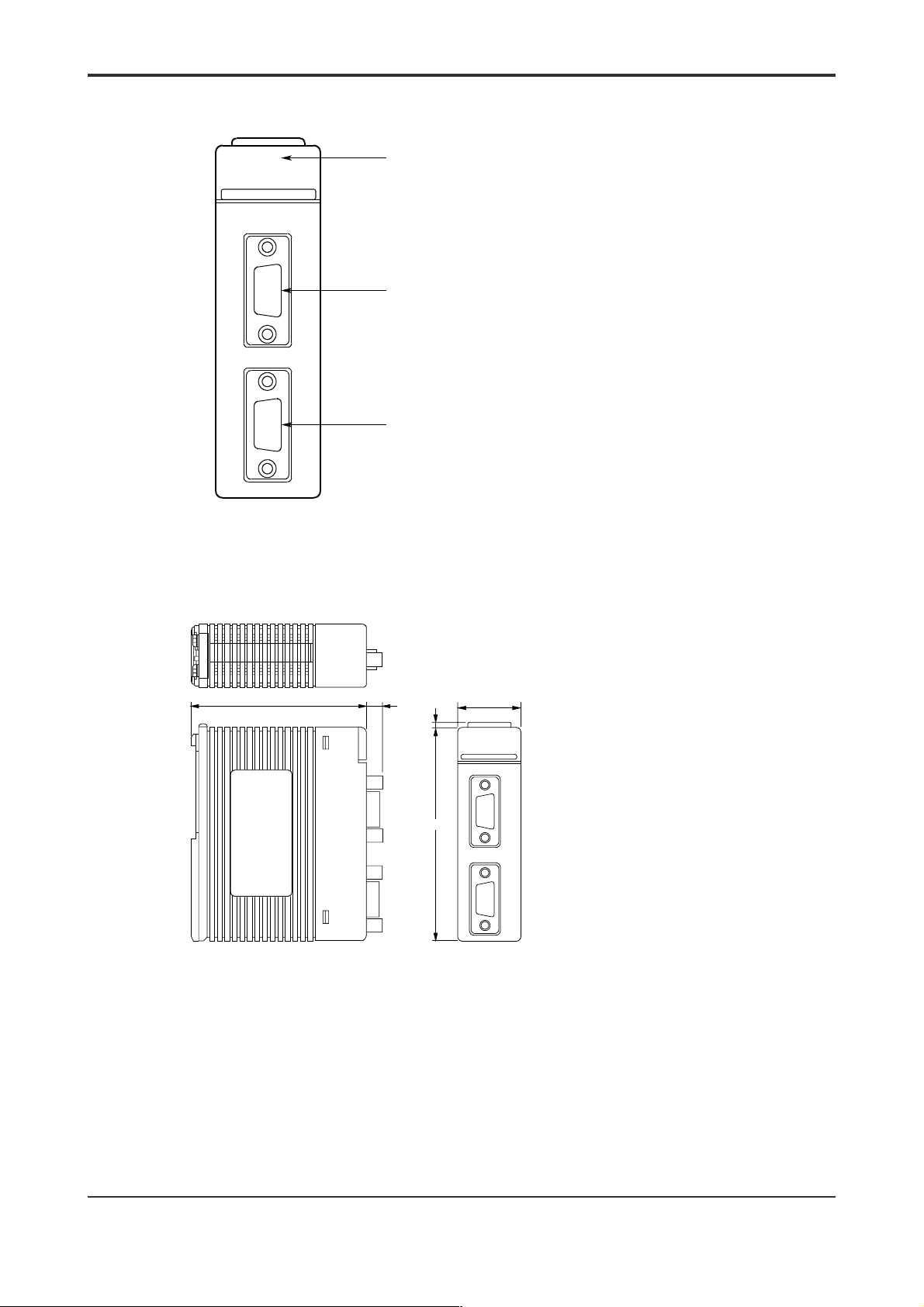
Components and Their Functions
2-3
RDY
RS22-0N
1
2
RS232C
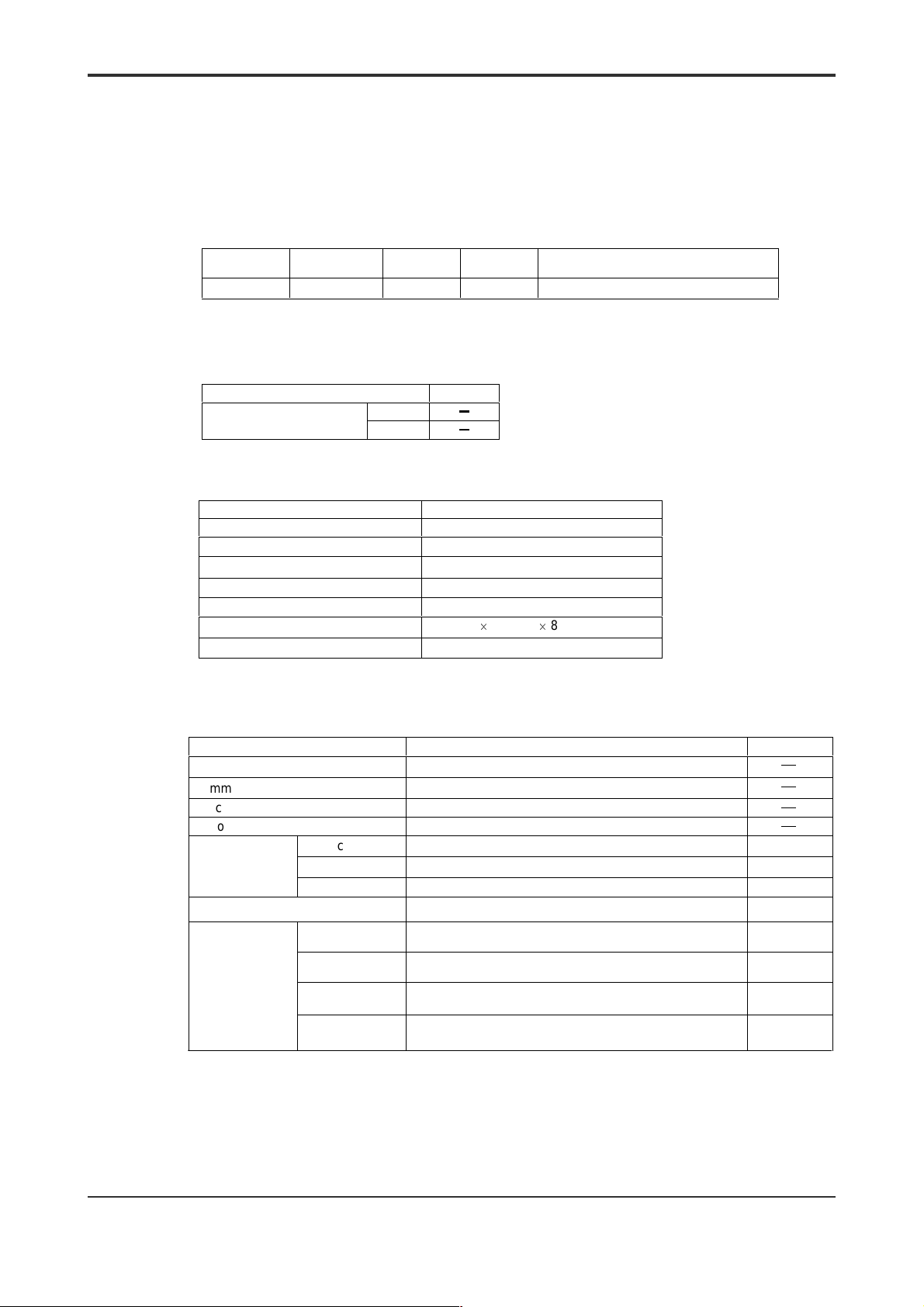
External Dimensions
READY indicator (lit when
the internal circuitry is in
normal operation)
Port 1
Port 2
(Unit: mm)
83.2 28.9
6.7
2
100
Note: When an RS-232-C cable is connected to the module, add 90 mm to the 83-mm depth across the bottom of t he
module to allow for approximately 173 mm as the mounting depth to accommodate the base module, the RS-232-C
connector and the bending radius of the RS-232-C cable,.
IM 34M6H21-01E 2nd Edition : Aug, 2001-00
Page 19
2.2 External Wiring
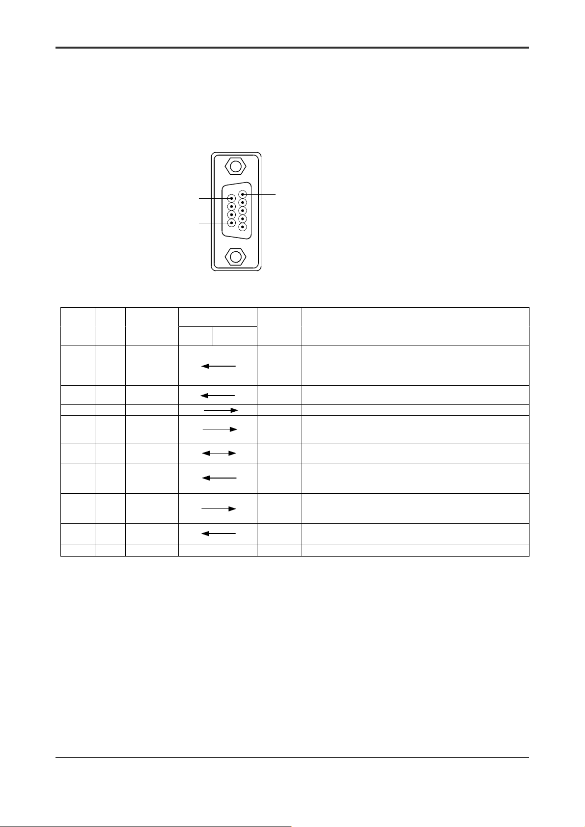
Connector Pin Assignments
The following figure shows how the module’s connector looks when viewed externally.
2-4
9
6
D-Sub 9-pin
Connector (Female)
5
1
Pin
Number
1 CD Data
2 RD Receive
3 SD Send Data no
4 ER Data
5 SG Signal
6 DR Data Set
7 RS Request to
8 CS Clear to
9 — Unused no no
Signal
Name
Name
Carrier
Detect
Data
Terminal
Ready
Ground
Ready
Send
Send
* : Option (1) or (2) c an be s et us ing a BASI C program.
Signal Directi on
FA-M3 Remote
equipment
no
no
yes Permission to transmit from the remot e equipment.
Signal
Monitoring
(yes/no)
yes
no
yes
no
Purpose *
Receives only when this signal is on. Sending pr oceeds
as follows:
(1) Transmits regardless of the state of CD (default).
(2) Transmits only when CD is off.
(1) ER turns on when power is switched on and stays on
(default).
(2) Turns on and off by software
Used to check if remote equipment is ready for receiving
(1) Receives regar dless of the state of DR (default).
(2) Receives only when DR is on.
Used when transmitting data to the remote equipment
(1) Always on (default).
(2) Turns on only during transmis sion
Transmits only when this signal is on.
IM 34M6H21-01E 2nd Edition : Aug, 2001-00
Page 20
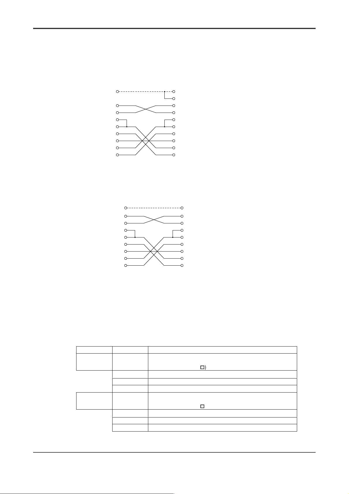
Directly Connecting to an RS-232-C Device (DTE: Data Terminal
Equipment)
Example internal cable connection diagram for D-sub 25-pin remote
z
equipment
2-5
Null-modem cable
Pin no.
Connector cover
(SD) 3
(RD) 2
F3RS22-0N
D-sub 9-pin
Note: This example illustrates the case where the remote DTE uses D-sub 25-pin.
(RS) 7
(CS) 8
(DR) 6
(SG) 5
(CD) 1
(ER) 4
Examples of cables with the above internal connection are the YCB cables supplied by Yokogawa.
Shield
Pin no.
Connector cover
1 (FG)
2 (SD)
3 (RD)
Remote DTE
4 (RS)
(D-sub 25-pin)
5 (CS)
6 (DR)
7 (SG)
8 (CD)
20 (ER)
z Example internal cable connection diagram for D-sub 9-pin remote
equipment
Null-modem cable
Pin no.
Connector cover
(SD) 3
(RD) 2
F3RS22-0N
D-sub 9-pin
(RS) 7
(CS) 8
(DR) 6
(SG) 5
(CD) 1
(ER) 4
Shield
Pin no.
Connector cover
3 (SD)
2 (RD)
7 (RS)
Remote DTE
8 (CS)
D-sub 9-pin
6 (DR)
5 (SG)
1 (CD)
4 (ER)
z Connect the shielded wire as instructed below:
(1) Use a cable with connectors housed in metal or metal-plated covers. Connect the
shielded wire directly to the connector covers.
(2) Note that the connector shell of an F3RS22-0N module is connected internally to
the FG (frame ground) terminal of an FA-M3 power supply module.
z Introduction to Yokogawa-supplied cables
The following null modem cables are available from Yokogawa.
Model Code Suffix Code Specifications
YCB215 RS-232-C null modem cable (with control line) with 9- and 25-pin
-KM01
-KM05
-KM15
YCB216
-KM01
-KM05
-KM15
Note: These cables should be terminated for indoor use.
connectors
ML gateway card (CP7
) for connecting RS-232-C devices.
1 m long
5 m long
15 m long
RS-232-C null modem cable (without control li ne) with 9- and
25-pin connectors
ML gateway card (CP7
) for connecting RS-232-C devices
1 m long
5 m long
15 m long
IM 34M6H21-01E 2nd Edition : Aug, 2001-00
Page 21

z Diagrams of internal cable connections
2-6
YCB215
CN1 side (FA-M3)
PIN No.
Connector cover
Shield
SD
3
RD
2
RS
7
CS
8
DR
6
SG
5
CD
1
ER
4
FG
SD
RD
RS
CS
DR
SG
CD
ER
CN2 side
PIN No.
Connector cover
1
2
3
4
5
6
7
8
20
YCB216
CN1 side (FA-M3)
PIN No.
Connector cover
CN2 side
Shield
SD
3
RD
2
RS
7
8
CS
6
DR
5
SG
1
CD
4
ER
FG
SD
RD
SG
PIN No.
Connector cover
1
2
3
7
Connecting to a Modem (DCE: Data Communication Equipment)
z
Internal cable connection diagram for D-sub 25-pin remote equipment
Modem cable
F3RS22-0N
(D-sub 9-pin)
Note: This example illustrat es t he c as e where the remote DCE uses D-sub 25-pin.
Pin No.
Connector cover
(SD) 3
(RD) 2
(RS) 7
(CS) 8
(DR) 6
(SG) 5
(CD) 1
(ER) 4
An example of a cable with the above internal connection is the YCB211 cable supplied by Yok ogawa.
Pin No.
Connector cover
1 (FG)
2 (SD)
3 (RD)
4 (RS)
Remote DCE
5 (CS)
(D-sub 25-pin)
6 (DR)
7 (SG)
8 (CD)
20 (ER)
IM 34M6H21-01E 2nd Edition : Aug, 2001-00
Page 22

CN2 side
z Internal cable connection diagram for D-sub 9-pin remote equipment
Modem cable
Connector cover
F3RS22-0N
(D-sub 9-pin)
z Connecting using sheilded cables
(1) Use a cable with connectors housed in metal or metal-plated covers. Connect the
shielded wire directly to the connector covers.
(2) Note that the connector shell of an F3RS22-0N module is connected internally to
the FG (frame ground) terminal of an FA-M3 power supply module.
z Introduction to Yokogawa-supplied cables
Pin No.
(SD) 3
(RD) 2
(RS) 7
(CS) 8
(DR) 6
(SG) 5
(CD) 1
(ER) 4
Pin No.
Connector cover
3 (SD)
2 (RD)
7 (RS)
Remote DCE
8 (CS)
(D-sub 9-pin)
6 (DR)
5 (SG)
1 (CD)
4 (ER)
2-7
The following modem cables are available from Yokogawa. The model codes,
specifications and wiring diagrams of these cables are summarized below:
Model Name
YCB211 RS-232-C modem cable (without control line) wi th 9- and 25-pin connector s
Note: These cables should be terminated for indoor use.
Suffix Code Specification
) for connecting modems.
-KM01
-KM05
-KM15
ML gateway card (CP7
1 m long
5 m long
15 m long
z Diagrams of internal cable connections
YCB211
CN1 side (FA-M3)
PIN No.
Connector cover
3
2
7
8
6
5
1
4
9
SD
RD
RS
CS
DR
SG
CD
ER
CI
Shield
FG
SD
RD
RS
CS
DR
SG
CD
ER
CI
PIN No.
Connector cover
1
2
3
4
5
6
7
8
20
22
IM 34M6H21-01E 2nd Edition : Aug, 2001-00
Page 23

Notes on Wiring
The connector shell of an F3RS22-0N module is connected internally to the FG terminal
of an FA-M3 power supply module.
(1) When connecting the F3RS22-0N module via a modem:
The module should be no more than 5 m away from the modem.
(2) When connecting the F3RS22-0N module not via a modem:
Ground the module in common with the remote equipment.
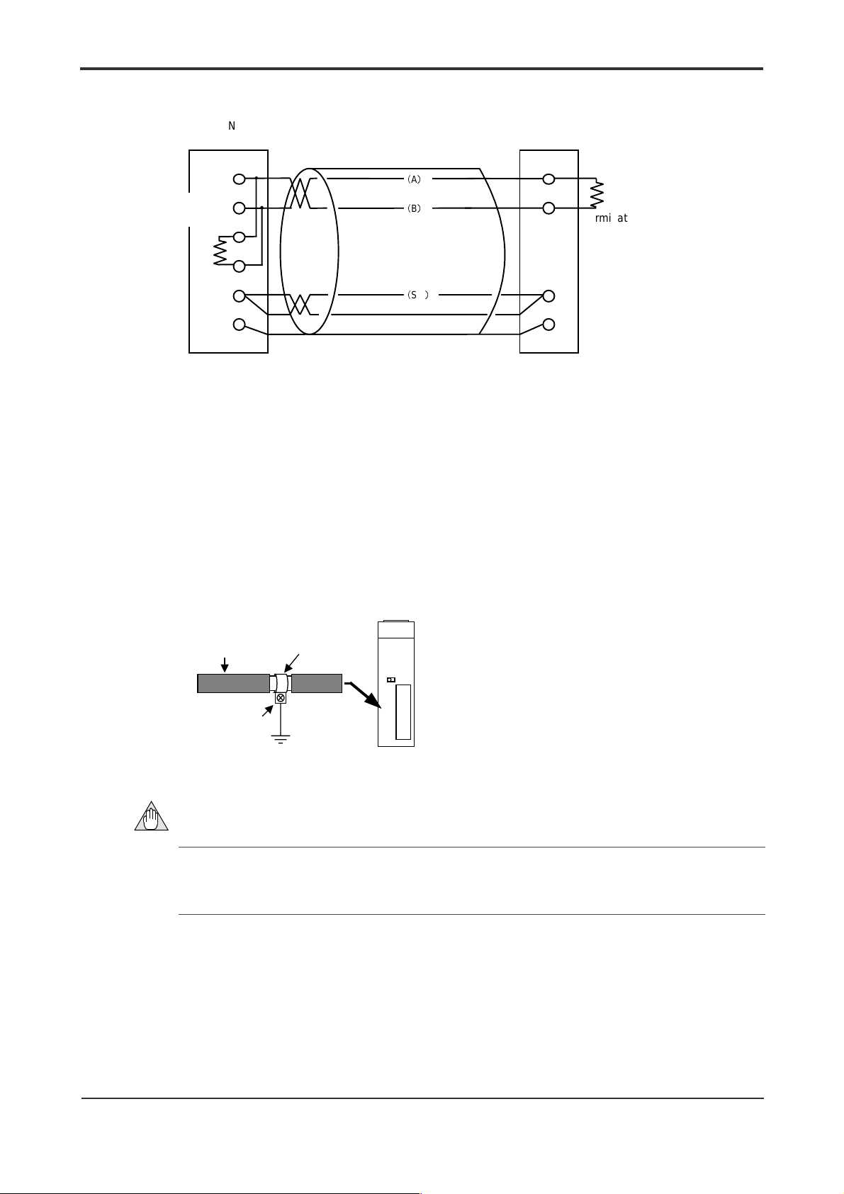
(3) For conforming equipment incorporating the F3RS22-0N to CE Marking, use a
shielded cable. Remove the cable cover to expose the wire, ground and secure the
wire with a FG clamp.
FA-M3 Remote
equipment
FG
JIS Class 3 grounding
(grounding resistance of 100
:
or less)
2-8
Shielded cable
Remove the cover
and secure with an
FG clamp.
F3RS22-0N
Screw the
clamp to the
metal plate o f
the panel
enclosure to
ground it.
IM 34M6H21-01E 2nd Edition : Aug, 2001-00
Page 24
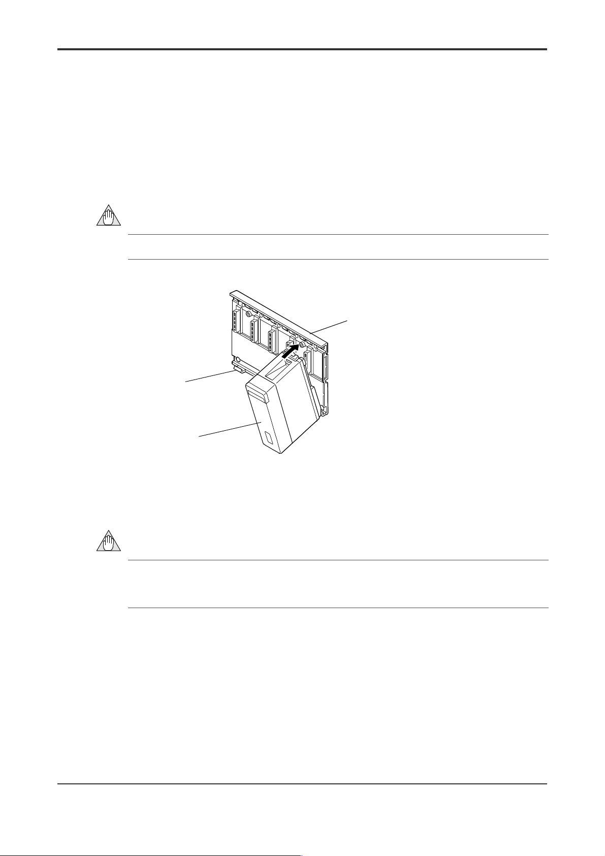
2.3 Attaching and Detaching Modules
Attaching/Detaching Modules
Figure 2.1 shows how to attach this module to the base module. First hook the anchor
slot at the bottom of the module to be attached onto the anchor pin on t he bot t om of
the base module. Push the top of this module towards the base module until the
anchor/release button clicks into place.
2-9
CAUTION
Always switch off the power before attaching or detaching a module.
Anchor pin
Counter module
Figure 2.1 Attaching Modules
Base module
F01.VSD
CAUTION
DO NOT bend the connector on the rear of the module by force during the above
operation. If the module is pushed with improper force, the connector may bend causing
an error.
Detaching Modules
To remove this module from the base module, reverse the above operation. Press the
anchor/release button on the top of this module to unlock it and tilt the module aw ay
from the base module. Then lift the module off the anchor pin at the base.
IM 34M6H21-01E 2nd Edition : Aug, 2001-00
Page 25

Attaching Modules in Intense Vibration Environments
If the module is used in intense vibration environments, fasten the module with a screw.
Use screws of type listed in the table below. Insert these screws into the screw holes on
top of the module and tighten them with a Phillips screwdriver.
M4-size Binder screw 12 to 15 mm long
(or 14 to 15 mm if fitt ed with a washer)
Figure 2.2 Tightening the Module
Screw Required
F02R1.VSD
2-10
IM 34M6H21-01E 2nd Edition : Aug, 2001-00
Page 26
3. F3RS41-0N Communication Module
3.1 Standard Specifications
Model and Suffix Codes
3-1
Model Code Suffi x Code Style Code
F3RS41 -0N
Operating Environment
F3RS41-0N can be used with the following CPU modules.
CPU Modules
BASIC CPU module
Physical Specifications
Item Specifications
Interface EIA RS-422A, EIA RS-485 compliant
Number of communication ports 1 (isolated)
Maximum number of
connectable drivers or receivers
Transmission distance 1,200 m maximum
Connector Six-pole terminal block with 3.5-mm scr ews
Current consumption 210 mA (5 V DC)
Dimensions 28.9 (W)
Weight 110 g
Additional
…… ……
F3BP20
F3BP30
RS-422A RS-485
1 driver
10 receivers
Code
Max. 19200 bps, one RS-422-A/RS485 port
Style
u
100 (H) u 83.2 (D) (mm)
32 drivers
32 receivers
Remarks
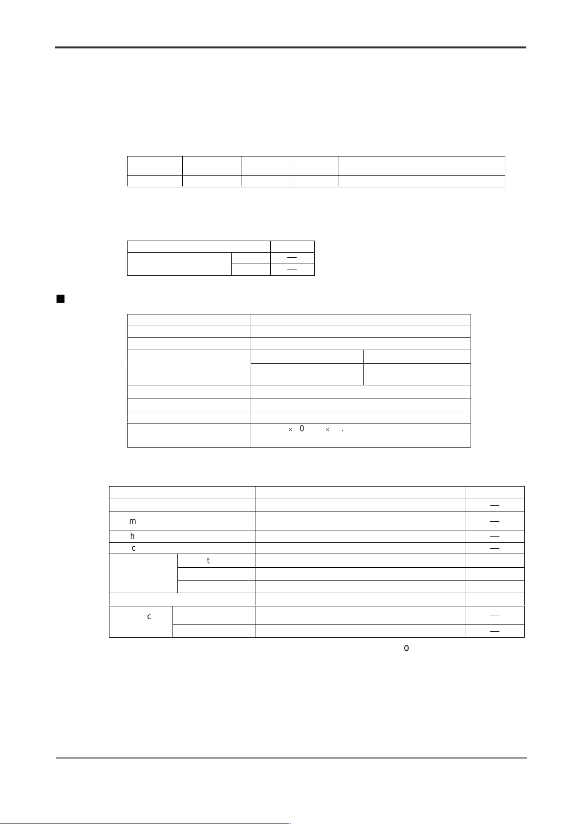
Function Specifications
Item Specifications Default
Connection Point-to-point (multipoint also allowed)
Communication mode
Synchronization Start-stop
Protocol Non-procedural
Character length 7/8 bits 8 bits
Character frame
Transmission rate 75/150/300/600/1200/2400/4800/9600/ 19200 bps 4800
Communication
buffer
Stop bit length 1/1.5/2 bits 1 bit
Parity bit None/odd/even Even
Transmitting buffer
Receiving buffer Rotary ( FIFO) buffer of 2,048 bytes
Full-duplex/half-dupl ex
4-wire sytem/2-wire system
Can buffer one text item (maximum lengt h of 1,024
bytes)
(to be continued on the next page)
IM 34M6H21-01E 2nd Edition : Aug, 2001-00
Page 27
Item Specifications Default
Starting character
- Yes/no
- One-character length; any charact er is acceptable
No
- Yes/no
Ending character
(Terminator)
- Two-character length maximum; any character
(string) i s acceptable
- Also serves as an ending character during
x
$0D
(CR-LF)
transmission.
Receive text
format
Designation of
number of character s
Monitored characterto-character time
interval
- Yes
- Effective range: 1 to 1024 (over the communication
line)
- Configurable in 1-ms units; precis ion: 10 ms
- Effective range: 0 to 32767 (if set to 0, there is no
monitoring of the character-to-c haracter time
interval)
1024
1.5s
Character-tocharacter receiving
interval time-out
Processed as a communication failure/processed as
the normal end of receiving
Normal end of
receiving
process
(1) Uncontrolled
(2) Receiving line only
(3) Transmitting line only
(4) Both transmitting and receiving lines
One-character length; any character acceptable
Uncontrolled
$13(DC3)
XON/X
control
OFF
Control method
XON character $11(DC1)
character
X
OFF
Internal code
Transmission code Internal code/ASCII code*1/JIS 8-bit code*2
(ASCIIequivalent)
Monitored time before I /O completion
Break transmis sion interval
Interruption
mask
*1 During input, k ana and k anji characters are replaced with spaces.
*2 During output, kanji charac t ers are replac ed with JIS double-byte codes, while other characters not def ined as J I S
Note: JIS c ode s yst em s : J I S X0201, JI S X0208
End of receiving Interruption permitted/prohibited Prohibited
Receive failure Interrupt ion permitted/prohibited Prohibited
Break receiving
characters are replaced with spaces.
Interruption permitted/prohibited Prohibited
Configurable in 1-ms uni ts from 1 to 32760 ms;
precision: 10 ms
Configurable in 1-ms uni ts from 1 to 32760 ms;
precision: 10 ms
30 ms
400 ms
3-2
$0A
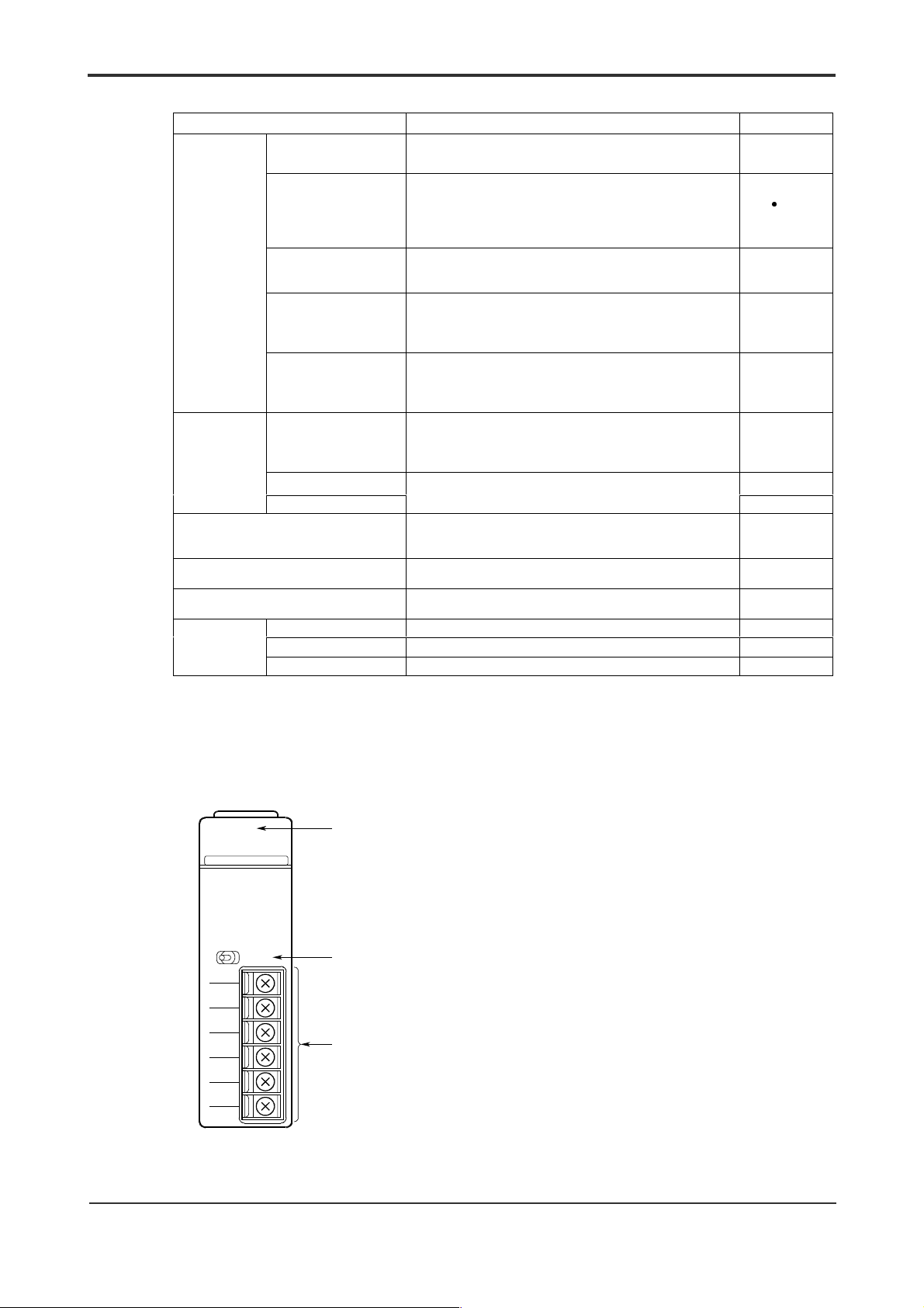
Components and their Functions
RDY
RS41-0N
TERMINATOR
2- 4-WIRE
OFF
SD A
SD B
RD A
RD B
SG
SHIELD
RS422
READY indic ator:
(lit when the internal circuit is in
normal operation)
Teminating resistor selector switch:
When the module is terminal in the
line, use this switch to select either
"4-WIRE" or "2-WIRE."
RS-422/RS-485 terminal block
(Six terminals with 3.5-mm screws)
IM 34M6H21-01E 2nd Edition : Aug, 2001-00
Page 28

External Dimensions
3-3
(Unit: mm)
83.2 28.9
12.1
2
100
IM 34M6H21-01E 2nd Edition : Aug, 2001-00
Page 29

Remote equipment
Terminating resistor
3.2 External Wiring
This subsection explains the point-to-point wiring methods.
For multi-point connection, see Section 4.6, “Multi-point Connections.”
For two-wire systems, register setting is required. See Section 4.6 " Setting Registers".
RS-422/RS-485 Terminal Block
3-4
SD A
SD B
RD A
RD B
SG
SHIELD
Applicable wire Size: 0.3 to 1.25 mm2 thick
Wiring method Crimp-on
Crimp-on
terminal
Connection Terminal block
Four-Wire System
F3RS41-0N module’s
port terminals
SD A
Send data A
SD B
Send data B
RD A
Send data A
RD B
Send data B
Signal ground
SG
SHIELD SHIELD terminal
o
o
7.3mm
o
o
(AWG 22 to 18)
Example: CO-SPEV-SB (A) 3P
Cable, Limited.
Crimp-on terminal For 3.5-mm size
Tightening torque 0.8 N. m
Applicable cri m p-on
terminal
Examples:
V1.25-M3 from J.S.T. Mfg. Co. Ltd.
RAV1.25-3.5 from Nippon Tanshi Co., Ltd.
M3.5
8.6mm
u
0.5 SQ from Hitachi
Terminating resistor
(built-in)
Set the terminati ng res istor selector swtich to a 4-wire system.
SG
SHIELD
SDA
SDB
RDA
RDB
(SD A)
(SD B)
(RD A)
(RD B)
(SG)
SD
A
SD
B
RD
A
RD
B
SG
SHIELD
IM 34M6H21-01E 2nd Edition : Aug, 2001-00
Page 30
Remote equipment
Terminating resistor
Two-Wire System
3-5
Terminating resistor
F3RS41-0N module’s
port terminals
SDA
SDB
(built-in)
Set the terminati ng res istor selector swtich to a 2-wire system.
RDA
RDB
SG
SHIELD
Notes on Wiri ng
(1) Ground the cable for the twisted pair at two ends (by connecting it to the SHIELD or
the FG terminal). The SHIELD terminal on the F2RS41-0N is connected to the FG
terminal internally.
(2) The F3RS41-0N has a built-in terminating resistor (220:), which can be set to a 4-
wire system or a 2-wire system using the terminating resistor selector switch.
(3) For conforming equipment incorporating the F3RS41-0N to CE Marking, use a
shielded cable. Remove the cable cover to expose the wire, ground and secure the
wire with a FG clamp.
Shielded cable
Screw the
clamp to the
metal plate of
the panel
enclosure to
ground it.
Remove the cover
and secure with an
FG clamp.
A
B
SG
F3RS41-0N
A
B
SG
SHIELD
3.3 Att aching and Detaching Modules
CAUTION
Even if the F3RS41-0N module is properly connected, error such as a flashing LED may
still occur because the signal polarities (represented as A/B) ar e r eversed with respect
to that of the remote equipment. In such case, change the connection accordingly.
See Section 2.3, "Attaching and Detaching Modules".
IM 34M6H21-01E 2nd Edition : Aug, 2001-00
Page 31

Blank Page
Page 32

4. Using the Communication Module
4.1 Basic Communications
Declar ing Use of the Module
Use the ASSIGN statement to declare use of the module.
ASSIGN module ID = S(, module ID=S, …)
Module ID: RS22…F3RS22–0N
RS41…F3RS41–0N
S: Slot number
(Example) ASSIGN RS22=5, RS42=6
An example is illustrated for F3RS22–0N in the sample program hereaft er.
F3RS41–0N can also be declared similarly since the difference lies only in the module
ID of the ASSIGN statement.
4-1
Resetting the Module
The communication module can be reset using the RESET statement. Always reset the
buffer after setting the communication conditions.
Table 4.1 RESET Statement
Module
Reset
Port Reset RESET 5, 1 9 9
Buffer Reset RESET 5, 1, 1 9 u
Note: This example uses s lot num ber 5 and port num ber 1.
For the F3RS41–0N module, which has only one port, Module Reset and t he Port Reset produc e t he s ame result.
Example (note)
RESET 5
Communication
buffer
9 9
Setting Communi cation Conditions
The communication conditions such as data transfer rate and parity must be set using
software. Values for the communication conditions are written to and read from
registers in the module using CONTROL/STATUS statement s.
CONTROL S
*: F3RS41-0N module does not support port 2.
STATUS S,P,R;Para
,P,R;Para
Setting value
Register number
Port number (1 or 2
Slot number
Storage variable (integer)
Communication
conditions
*
)
Remarks
The communication conditions for the
module reverts to default .
The communication conditions for Port 1
reverts to default.
The communication condition remains
unchanged.
IM 34M6H21-01E 2nd Edition : Aug, 2001-00
Page 33

(Example)
When using slot number 5, port 2 at 9600bps, odd parity with 2 stop bits,
10 ASSIGN RS22=5
20 RESET 5,2 : !Port Reset
30 CONTROL 5,2,14;7 : !9600 bps
40 CONTROL 5,2,13;1 : !parity Odd
50 CONTROL 5,2,12;2 : !2 Stop bits
60 RESET 5,2,1 : !Buffer Reset
The main registers for setting the communication conditions are shown in Table 4.2.
See Table 4.7 in Section 4.4 for a list of all the registers.
Table 4.2 List of Main Registers for Setting Communication Conditions
Data Position
Number
11 S/C Character length
12 S/C Stop bit length
13 S/C Parity
14 S/C
S/C: status/control register
Type of
Register
Contents Default Value
Data transfer rate
(bps)
0: 7 bits
1: 8 bits
Others: 8 bits
0: 1 bit
1: 1.5 bits
2: 2 bits
Others: 2 bits
0: none
1: odd
2: even
Others: even
0: 75
1: 150
2: 300
3: 600
4: 1200
5: 2400
6: 4800
7: 9600
8: 19200
others: 19200
1
0
2
6
4-2
Output
Use the OUTPUT statement to send t ext .
OUTPUT S,P;output data
Numeric values or variables, or character strings or c haracter string
variables.
Enclose numeric values or character strings within doubl e quotes (“).
(Example)
To send the character string “ABCDE” from slot 5, port 2,
OUTPUT 5, 2; “ABCDE”
The ending characters CR-LF (default value) are added and output on the line as
shown below.
A B C D E
CR LF
IM 34M6H21-01E 2nd Edition : Aug, 2001-00
Page 34

Input
4-3
Use the ENTER statement to retriev e received text.
The ENTER statement extracts from the rotary buffer text. The text is delineated using
the ending character, character-to-character time out or the number of characters
received.
ENTER S,P;input variables
(Example)
To receive text from slot 5, port 2,
ENTER 5, 2; RCVDT$
The receive text from the rotary buffer is stored in the input variable RCVDT$ (string
variable).
S 1 2 3 4
In the above example, the receive variable RCVDT$ is set as follows.
RCVDT$=”S1234”+CHR$($0D)+CHR$($0A)
Although the ENTER statement can be used alone for receiving, the system will remain
in wait state until receive complete s if the receive text is not in the rotary buffer. Hence,
it is recommended that you use the ENTER statement toget her w it h t he ON INT
statement so that control transfers to the ENTER statement only when receive text has
entered the rotary buffer.
Variables or array variables of numeric type or character stri ng type.
CR LF
IM 34M6H21-01E 2nd Edition : Aug, 2001-00
Page 35

4-4
4.2 Transmission Text and Format Specifications
Data Output
Data output is performed with the OUTPUT statement.
The OUTPUT statement can be used to specify t he out put format, as well as whether a
terminator is to be appended and code conversion to be performed before output.
Table 4.3 Format Specification using the OUTPUT statement
Type Statement Terminator Code Conversion
I OUTPUT S, P, ~
II OUTPUT S, P, ~
III OUTPUT S, P NOFORMAT; ~ Not appended No (YM – BASIC/FA internal
S: Slot number P: Port number
OUTPUT S P USING “~”, ~
OUTPUT S P USING “#,~”, ~
z Type I
The output data undergoes code conversion, the terminator is appended aut omatically
and the data is output to the line. I f t here is an image specification, it follow s the image
specification. For details on the format of the image specification, refer to the IMAGE
statement in the user’s manual “BASIC CPU Modules and YM - BASI C/F A Programming
Language” (IM34M6Q22-01E). The terminator can be specified as any character st ring
of two or less characters. The default is CR-LF.
BASIC program Data on the line
10 ASSIGN RS22=5
20 A$=”ABCD”: B=100
30 OUTPUT 5,2;A$;B
40 OUTPUT 5,2 USING”3A,MDDZ.Z”;A$;B
Note: The above real variable B is converted to a c harac t er s t ring bef ore out put .
A B C D
A B C
appended
automatically
Not appended
(appended by user)
Yes
Yes
code)
1 0 0
1 0 0
.
CR LF
0
CR LF
z Type II
The output data undergoes code conversion before output. No terminator is appended.
If a terminator is required, the user has to ensure that it is appended during output.
BASIC program
10 ASSIGN RS22=5
20 A$=”ABCD”: B=100
30 TERM$=CHR$($0D)
40 OUTPUT 5,2;A$;B;TERM$;
50 OUTPUT 5,2 USING”#,3A,MDDZ.Z,2A”;A$;B;TERM$
Data on the line
A B C D
A B C
1 0 0
1 0 0
IM 34M6H21-01E 2nd Edition : Aug, 2001-00
.
CR
0
CR
Page 36

z Type III
The output data is output as internal code. No terminator is appended.
Code conversion is ignored, even if specified.
BASIC program Data on the line
10 ASSIGN RS22=5
20 A$=”ABCD”: B=100
30 OUTPUT 5,2 NOFORMAT;A$;B
Data Input
Data input is executed with the ENTER statement.
The ENTER statement can be used to specify the input format, as w ell as w hether a
terminator is to be removed and code conversion to be performed after input.
Table 4.4 Format Specification using the ENTER Statement
Type Statement Terminator
I ENTER S, P, ~
ENTER S P USING “~”, ~
II ENTER S, P, ~
ENTER S P USING “#,~”, ~
III ENTER S, P NOFORMAT; ~ No change No
S: Slot number P: Port number
A B C D
No change Yes
Removed
automatically
4-5
Numeric data (internal c ode)
Code
Conversion
Yes
z Type I
The data on the line undergoes code conversion and is stored into the input variable
with the terminator attached as is. I f t here is an image specification, it follows the image
specification. For details on the format of the image specification, refer to the IMAGE
statement in the user’s manual “BASIC CPU Modules and YM - BASI C/F A Programming
Language” (IM34M6Q22-01E).
(Example)
This example shows receiving of the following data on the line from port 2 of slot 5
where the terminator is CR-LF.
Data on the line
BASIC program
1000 ENTER 5,2;A$
1010 ENTER 5,2 USING 1020;B$;c;D$
A B C D
1020 IMAGE 4A,6N,2A
A B C D 1 0
The value of each variables is as shown below.
A$ = ”ABCD” + CHR$($0D) + CHR$($0A)
B$ = ABCD”
C = 100
D$= CHR$($0D) + CHR$($0A)
CR
LF
0
0 .
CR
LF
z Type II
The data on the line undergoes code conversion, the terminator (if present) is removed
and the data is stored in the input variable. If there is an image specification, it follows
the image specification For details on the format of the image specification, refer to the
IMAGE statement in the user’s manual “BASIC CPU Modules and YM-BASIC/FA
Programming Language” (IM34M6Q22-01E).
IM 34M6H21-01E 2nd Edition : Aug, 2001-00
Page 37

(Example)
This example shows receiving of the following line data from port 2 of slot 5 when
the terminator is CR-LF.
BASIC program Data on the line
1010 ENTER 5,2 FORMAT;A$
1020 ENTER 5,2 FUSING 1030;B$;C
1030 IMAGE 4A,6N
A B C
A B C D
.
1 0 0
CR
LF
.
The value of each variable is as shown below.
A$=“ABCD”
B$=“ABCD”
C=100
z Type III
The data on the line does not undergo code conversion and is stored in the input
variable unchanged. The terminator, even if present, is not removed.
(Example)
The example shows receiving of the following line data from port 2 of slot 5.
BASIC program Data on the line
10 DEFINT K
1010 ENTER 5,2 NOFORMAT;A$
1020 ENTER 5,2 NOFORMAT;K
A B C D
Binary data ($0001)
The value of each variable is as shown below.
A$=“ABCD”+CHR$($0D)+CHR$($0A)
K=1
(no terminator)
CR
LF
0 D
4-6
CR LF
IM 34M6H21-01E 2nd Edition : Aug, 2001-00
Page 38

4.3 Efficient Communication
Interrupt Input
Interrupt Input performs input from the communication line and after receiving of the
transmission text is completed, an interrupt is sent t o t he BASIC program. When
Interrupt Input is used, the BASI C pr ogr am can continue w it h ot her pr ocessing even
whilst the actual communication process is executed by the module processor. The
data is accepted after receiving has been completed, hence improving performance.
The following two statements are used for Interrupt Input .
(1) ON INT
This statement declares an interrupt and specifies the branch points for a port.
ON INT S,P CALL Subprogram name
GOSUB
GOTO
Use the OFF INT statement t o cancel an O N INT statement declaration.
OFF INT S,P
Label
Line no.
Label
Line no.
4-7
(2) ENABLE INTR
To pass the text saved in the buffer within the module to a BASIC program, the I/O
interrupt request mask within the module must be switched to an unmasked state.
By executing this statement, when an interrupt to BASIC occurs, t he r eceived text saved
in the buffer can be passed to BASIC using ENTER.
Since the corresponding I/O interrupt request mask switches to the masked state for
every port reset and interrupt branching, set t he unmasked stat e again using ENABLE
INTR.
ENABLE INTR S,P;”x
1 x2 x3
S: slot number P: port number
and X3 may be omitted. They are zero when omitted.
X
2
1: Branching of interrupt using ON INT stat ement when receiving completes.
x
1
0: Interrupt is disabled. The received text is saved in the buffer.
1: Branching of interrupt using ON INT stat ement when error occurs during receiving. The received
x
2
0: Interrupt is disabled. The received text containing the error is dis carded.
1: Branching of interrupt using ON INT stat ement when a break is received. The received text
x
3
0: Interrupt is disabled. The received text containi ng the break is discarded.
text containing the error is discarded.
containing the break is disc arded.
”
Break received
Error during receiving
Receiving completed
IM 34M6H21-01E 2nd Edition : Aug, 2001-00
Page 39

4-8
(Example)
10 DEFINT I
20 ASSIGN RS22=5
50 ON INT 5,2 GOSUB INT@ … Specify interrupt destination
70 ENABLE INTR 5,2;”111” … Remove interrupt mask
Main program
100 INT@
110 STATUS 5,2,2;I
120 IF I = 0 THEN Interrupt handling
130 ENTER 5,2,;REC$
140 ELSE
150 PRINT “RECEIVE ERROR”
160 ENDIF
170 ENABLE INTR 5,2;”111”
180 RETURN
Line 70 enables interrupts for all reasons. Once an interrupt is raised, any further
interrupt from the corresponding port will be automatically disabled. Therefore, you
need to re-enable the interrupt before you exit this subroutine.
If multiple interrupt reasons are enabled (unmasked), use the STATUS statement t o read
the interrupt request status (register number 2), to det ermine whether t he ENTER
statement can be executed. Executing the ENTER st at ement for any int errupt other
than the End of the Receiving interrupt w ill cause an er r or since the receive text would
already have been discarded.
TRANSFER
z
Proceeding Type
Module accessing using ENTER/OUTPUT is a complete return type of access where the
BASIC program is in a wait state from the beginning of t he oper at ion to its completion.
Although this waiting can be avoided using ON INT/ENABLE I NTR for the ENTER
statement (during input), for t he OUTPUT statement (during out put ) , the BASIC program
has to wait until the operation completes (see Figure 4.1). In such a situation, it is
convenient to use the Proceeding type of access with TRANSFER/ON EOT.
In the Proceeding type of module access, the BASIC progr am merely starts the module
communication whereas the processor within the card handles all subsequent inputoutput processing (see Figure 4.2). This type of access is part icularly effective when the
transmission text is long and the data transfer rate is low. Parallel input-output operation
with other I/O cards is also possible.
Note the following when accessing using TRANSFER.
- Access to the corresponding port
For a port started by TRANSFER, other accesses with the exception of HALT
- Error during execution of TRANSFER
Errors during the execution of TRANSFER can be discovered by reading the status
(TRANSFER, OUTPUT, CONTROL, etc) are disallowed (causes an error) until the
operation has completed. In the user program, manage the port with flags and
check whether the port can be used during TRANSFER initiation. Completion of
TRANSFER is reported by an ON EOT interrupt .
registers (register number 04) of the corresponding port during ON EOT branching.
The set values are similar to the BASIC det ailed er r or codes ( 82- XX). As there is
IM 34M6H21-01E 2nd Edition : Aug, 2001-00
Page 40

4-9
no ON ERROR branching, check the status register in the program.
BASIC program
in WAIT state
Figure 4.1 Time Chart for Complete Return Type of Access
Figure 4.2 Time Chart for Proceeding Type of Access
Time
Time
CPU
Free
CPU
Free
CPU
Busy
OUTPUT ENTER
CPU
Busy
ON EOT
TRANSFER FROM TRANSFER INTO
Transmission
destination
Data
Transmission
destination
&CVC
BASIC
program in
WAIT st ate
Time
CPU
Free
Time
CPU
Free
ON EOT
CPU
Busy
CPU
Busy
Transmission
destination
Data
Transmission
destination
&
C
V
C
*
Time until data
arrives from
remote
equipment
*
Time until data
arrives from
remote
equipment
z TRANSFER Procedure
The program procedure for input and output using TRANSFER is explained below. In
both cases, input/output buffers and input/out put variables are required in the user area.
- Output Procedure
Data is output to the input/output buffer within the user area. Then, TRANSFER is
started. Common variables cannot be used in the input/output buffer.
10 DEFINT I
20 DIM BUFF$256,A$256
30 A$=“ABCDE”
40 ASSIGN RS22=5
50 OUTPUT BUFF$;A$ … Output data to buffer
60 ON EOT 5,2 GOSUB RSEOT@ … Specify interrupt destination
70 TRANSFER 5,2FORMAT FROM BUFF$ … Initiate TRANSFER
Other processing
1000 RSEOT@ STATUS 5,2,4;IST
1010 IF IST<>0 THEN
1020 PRINT“TRANSFER ERROR”
1030 ELSE Interrupt processing for end of TRANSFER
1040 PRINT“TRANSFER END”
1050 ENDIF
1060 RETURN
IM 34M6H21-01E 2nd Edition : Aug, 2001-00
Page 41

4-10
- Input Procedure
Although interrupt branching using ON INT can be used in almost all situations,
TRANSFER is useful when you need to perform input time monitoring (SET
TIMEOUT/ON TIMEOUT) processing. Normally, interrupt input using ON INT is
used.
Data is output into the input/output buffer first and then read using ENTER.
Common variables cannot be used in the input/output buffer.
10 DEFINT I
20 DIM BUFF$ 256,A$256
30 ASSIGN RS22=5
40 ON EOT 5,2 GOSUB RSEOT@ … Specify interrupt destination
50 TRANSFER 5,2 INTO BUFF$ … Initiate TRANSFER
Other processing
1000 RSEOT@ STATUS 5,2,4;IST
1010 IF IST<>0 THEN
1020 PRINT “TRANSFER ERROR!”
1030 ELSE Interrupt processing for end of
TRANSFER
1040 ENTER BUFF$;A$
1050 PRINT A$
1060 ENDIF
1070 RETURN
z Format Specification
When specifying the format such as the addition of terminator in a TRANSFER
statement, match it with the format specification of t he ENTER/OUTPUT st atement used
for buffer input/output.
For details on the operation of each individual format type, see Section 4.2.
Table 4.6 Format Specification on Output
Type Format Specification of OUTPUT
I OUTPUT BUFF$
OUTPUT BUFF$ USING “~“; ~
II OUTPUT BUFF$
OUTPUT BUFF$ USING “#, ~“; ~
III OUTPUT BUFF$
NOFORMAT; ~
S: slot number P: port number BUFF$: name of I/O buffer
Table 4.6 Format Specification on Input
Type For mat Specification of ENTER
I ENTER BUFF$; A$
ENTER BUFF$ USING “~“; A$
II ENTER BUFF$ FORMAT; A$
ENTER BUFF$ USING “~“; A$
III ENTER BUFF$ NOFORMAT; A$ TRANSFER S, P NOFORMAT INTO
S: slot number P: port number BUFF$: name of I/O buffer
Format Specification of
TRANSFER
TRANSFER S, P FORMAT FROM
BUFF$
TRANSFER S, P FROM BUFF$ Not appended
TRANSFER S, P NOFORMAT
FROM BUFF$
Format Specification of
TRANSFER
TRANSFER S, P INTO BUFF$ Appended
TRANSFER S, P FORMAT INTO
BUFF$
BUFF$
Terminator
Appended
automatically
(appended by
user)
Not appended No (YM.
Terminator
automatically
Not appended
(appended by
user)
Not appended No (YM.
Code
Conversion
Yes
Yes
BASIC/FA
internal code)
Code
conversion
Yes
Yes
BASIC/FA
internal code)
IM 34M6H21-01E 2nd Edition : Aug, 2001-00
Page 42

4.4 Using Registers
F3RS22-0N and F3RS41-0N have many registers for handling various aspects of
transmission. This section describes the use of these registers.
List of Registers
4-11
Register
Number
17* S/C DR check
18* S/C CD check
19* S/C
Register
Type
01 S Input wait s tat us
02 S Int errupt request status
03 S Input data s tatus
04 S
05 S
06 S/C Transmission code
07 S/C
11 S/C Character length
12 S/C Length of stop bits
13 S/C Parity
14 S/C Data transfer rate (bps)
15 S/C
16 S/C
Output processing data
status
Input processing data
status
Character-to-character
receiving interval timeout .
processing
F3RS22-0N RS control
F3RS41-0N
F3RS22-0N RS control
F3RS41-0N
Transmission enabled
monitoring time
(DR control monitoring)
Send/receive
control
Send/receive
control
Contents Default Value
0 : no
others : waiting for input
0 : receive terminated normally
1 : error during receiving
2 : break received
Bit 5 : framing error
Bit 4 : overrun error
Bit 3 : parity error
Bit 2 : i nternal buffer overflow
Bit 1 : character-to-character recei vi ng i nterval timeout
Bit 0 : break received
A bit is “1” when the corresponding error occurs.
Output status for OUTPUT/TRANSFER statement
=0 : sending terminated normally
z
0 : sending terminated abnormally
INPUT status for ENTER/TRANSFE R s tat ement
=0 : receiving terminated normall y
z
0 : receiving terminated abnormally
0 : internal c ode
1 : ASCII
2 : JIS 8 unit
0 : receive terminated normally
1 : error during receiving 0
0 : 7 bits
1 : 8 bits
Others : 8 bits
0 : 1 bit
1 : 1.5 bits
2 : 2 bits
Others : 2 bits
0 : none
1 : odd
2 : even
Others : even
0 : 75
1 : 150
2 : 300
3 : 600
4 : 1200
5 : 2400
6 : 4800
7 : 9600
8 : 19200
others : 19200
0
0
0
0
0
0
1
0
2
6
0 : always ON
1 : ON only when sending
See Section 4.6 Setting Registers
0 : ER=OFF
1 : ER=ON
See Section 4.6 Setting Registers
0 : transmits regardless of the s tat e of DR
1 : transmits only when DR is ON
0 : transmits regardless of the s tat e of CD
1 : transmits only when CD is OFF
0 : no time-monitoring
1 to 32760 (ms) 0
0
1
0
0
IM 34M6H21-01E 2nd Edition : Aug, 2001-00
Page 43

second ending
Register
Number
101 C Send break 1 : start break sending
S: status register, C: control register, S/C: status /control regis ter
Register
Type
20 S/C
21 S/C
22 S/C
23 S/C
24 S/C
25 S/C X
26 S/C X
Time for sending break
signal
Starting character for
receive text
Ending character
(terminator)
Number of receive
characters
Monitored character-tocharacter time interval
ON/XOFF
ON/XOFF
control
characters
Contents Default Value
1 to 32760 (ms)
15
All zeroes when no starting character i s specified
15 8 7 0
first ending
character
First ending character = 0 when there is only one character
-
All zeroes when no ending character is specified
-
1 to 1024 (number of characters on the line)
0 to 32760 (ms)
(no character-to-character monitoring when value is 0)
0 : No control
1 : Receiving end onl y
2 : Transmitting end onl y
3 : Both transmitting end and receiving end
15
8 7
0
8 7
XON X
*: Not available for F3RS41-0N
Starting
character
character
OFF
4-12
400
0
0
x
$0A
$0D
x
LF )
( CR
1024
$11
(DC1
1500
0
x
$13
x
DC3)
0
Format of Received Text
The communications module detects the end of the received text and recognizes the
text in any of the following ways.
z Terminator received
The module identifies the end of text when the terminator (end-of-text character) is
received. The default value is CR-LF.
(Example) When the terminator is set to EXT ($03)
10 ASSIGN RS22=5
20 CONTROL 5,2,22;$0003 :!Set terminator.
30 RESET 5,2,1 :!Reset buffer.
A B C E F
Text 1
Received data
D
Text 2
ETX
G ETX
IM 34M6H21-01E 2nd Edition : Aug, 2001-00
Page 44
z Specification of number of receive bytes
The end of text is assumed when the specified number of bytes (1 to 1024) is received.
When the starting character for receive text is specified, the counting of the received
bytes starts from that character.
(Example 1) When the number of received bytes is set to 4 bytes:
10 ASSIGN RS22=5
20 CONTROL 5,2,23;4 :!Specify number of received bytes.
30 RESET 5,2,1 :!Reset buffer.
Received data
B
A C F G H E
Text 1
D
Text 2
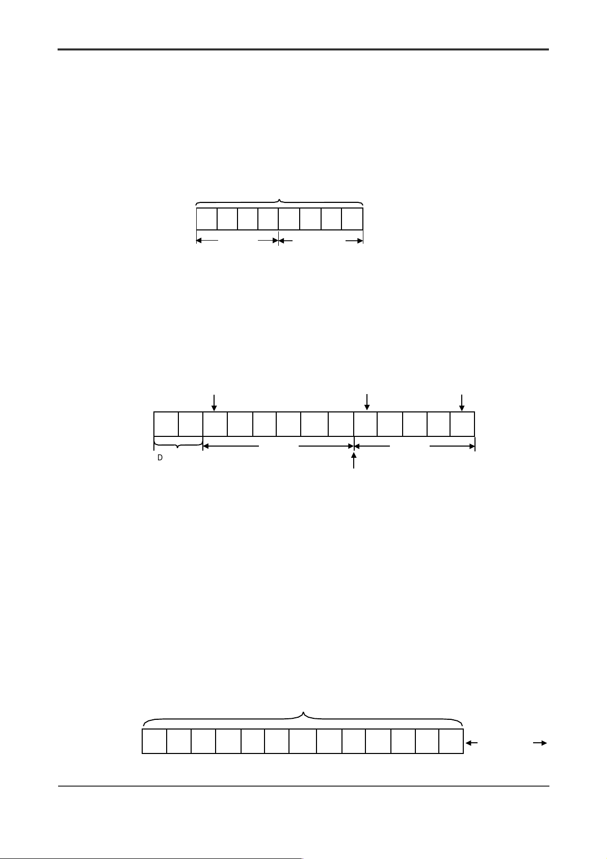
(Example 2) When the starting character is set to STX ($02), the number of received
bytes is set to 6 and the terminator is set to ETX ($03):
10 ASSIGN RS22=5
20 CONTROL 5,2,21;$0002 :!Specify starting character for received text.
30 CONTROL 5,2,23;6 :!Specify number of received bytes.
40 CONTROL 5,2,22; $0003 :!Set the terminator.
50 RESET 5,2,1 :!Reset buffer.
Starting character for
receive text
A B R N D
Discarded
P Q U
STX
Text 1
(6 bytes of received
characters)
If data is sent during thi s period,
They are not received as text.
Starting character for
receive text
E S
STX
(Terminator received)
Terminator
(End of Text)
ETX
Text 2
4-13
z Character-to-character receiving interval timer
The character-to-character receiving interval timer monitors the character-to-character
receiving time interval. When the next character is not received within the specified
time, end of text is assumed. This mode is useful for binary communications and text
with no terminator.
(Example) Received data (no terminator), character-to-character timer is 1 second
10 ASSIGN RS22=5
20 CONTROL 5,2,22;$0000 :!Set the terminator (no terminator).
30 CONTROL 5,2,7;0 :!Specify receive character-to-character
timeout processing
40 CONTROL 5,2,24;1000 :!Specify monitored character-to-character
receiving time interval.
50 RESET 5,2,1 :!Reset buffer.
Received data (with no terminator)
Time specified
1000 ms
Not considered a
receive error even if
timeout occurs
IM 34M6H21-01E 2nd Edition : Aug, 2001-00
Page 45

XON/X
Control
OFF
This feature prevents overflow in the communication buffer through the exchange of
special characters. This feature only applies in full duplex communications.
4-14
Table 4.8 XON/X
Classification Operation
Receiving end When the space in the input buffer falls below one quarter, transmit X
Transmitting
end
The system will switch to the X
port or buffer is reset. Any single character can be set as the X
(default is DC1/DC3).
(Example) When using X
10 ASSIGN RS22=5
20 CONTROL 5,2,25;3 :!Specify XON/XOFF control.
30 RESET 5,2,1 :!Reset buffer
However, XON/X
characters are not sent during text transmission.
Break Signal
Operation
OFF
.
OFF
When the space i n the input buffer rises above half, transmi t X
When data is received in the X
character is retransmitted. The character-to-character timer is inactive in
state and becomes active once XON is received.
the X
OFF
After the specified X
characters.
The received X
ON/XOFF
character is received, sending is stopped within 2
OFF
character is not passed as receive text to BASIC.
OFF
state when power is switched on or when t he module,
ON
control for both sending and receiving characters
state after X
OFF
transmission, the X
OFF
ON.
ON/XOFF
OFF
character .
control is only available in character communications. The XON/X
OFF
OFF
The break signal is a special signal that sends data containing a type of framing error
(all bits are “1”). This communication module handles break signal on both sending and
receiving.
z Sending a break
(example) Send the break signal after a 300 ms interval
1000 CONTROL 5,2,20;300 :!Specify send time for break signal
1010 CONTROL 5,2,101;1 :!Specify to send a break
z Receiving a break
Receiving a break signal causes an error (82-D4: receive error).
However, it can also be identified using an interrupt input. For details, see Section 4.3
IM 34M6H21-01E 2nd Edition : Aug, 2001-00
Page 46

4.5 Special Communications
Long Text
Be careful when handling long text (exceeding 512 bytes). All the following conditions
must be satisfied during sending.
- Data size transferred from a BASIC program to the communications driver is less
than 1 KB (including terminators)
- Line data after code conversion is less than 1 KB (including terminators)
(Example 1) Simple string variable
10 DIM A$512,B$500,
100 OUTPUT 5,2;A$;B$
(Example 2) An entire array
10 OPTION BASE1
20 DIM BUFF$ 500(2)
100 OUTPUT 5,2;BUFF$(*)
Similarly, during receiving, all the following condit ions have to be satisfied.
- Line text is less than 1 KB (including terminators)
- Data size transferred t o the input variable of the BASIC program is less than 1 KB
(including terminators)
In the YM-BASI C/ FA language specifications, a string variable has a maximum size of
512 bytes. Therefore, the input is performed by specify ing 2 or more variables. Not e
that if a 2-byte code (Katakana, Kanji, etc.) sp ans a variable boundary, the character
cannot be read.
4-15
(Example 1) Simple string variable
10 DIM A$512,B$512
20 ASSIGN RS22=5
30 ENTER 5,2;A$,B$
(Example 2) An entire array
10 OPTION BASE 1
20 DIM BUFF$512(2)
30 ASSIGN RS22=5
40 ENTER 5,2;BUFF$(*)
Binary Transmission
Binary transmission sends binary bit patterns instead of character codes on t he line.
It is used primarily for sending numeric data. It can be sent in the NOFORMAT
specification (Type III).
It can be received in the NOFORMAT specification (Type III) without any terminator and
using the character-to-character interval timer.
Under normal circumstances, use fixed text length transmission. In the case of
variable-length text, the text length can be det ermined with t he I O SI ZE function.
X
ON/XOFF
control is not available during binary transmission.
IM 34M6H21-01E 2nd Edition : Aug, 2001-00
Page 47

Handling Null Codes
In the YM-BASI C language specifications, the BASIC interpreter treats a null code ($00)
as a character string delimiter. If there is a null code embedded in a character string, the
null code and all subsequent characters are ignored. This is also the case during binary
transmission.
For sending and receiving with null codes, integer arrays can be used as input/out put
variables. However, note that access will be on a word boundary (2-bytes unit) in this
case.
A$="X"+CHR($00)+"Y"
is the same as
A$="X"+"Y"
To send null codes, use the following methods.
(1) Using an integer array as the output variable
Using the NOFORMAT specification, send word-bounded data as given below.
10 OPTION BASE 1
20 DEFINT K
30 DIM K(2)
100 K(1)=ASC("X")
110 K(2)=0
120 OUTPUT slot,port NOFORMAT;K(1)*256+K(2)
Note that, in the above example, when a character string with an odd number of
characters is sent, a null character is appended to the end so that there is an ev en
number of characters in the string.
(2) Specify ing data in by t es
Send data in bytes using image setting as shown below.
OUTPUT slot,port USING "#,B";K(*)
This method sends all data in array K(*) defined in the Dimension (DIM) statement.
To send v ariable size data, use a program as shown below.
200 II=5
210 FOR I=1 To II
220 OUTPUT slot,port USING "#,B";K(I)
230 NEXT I
This method sends only the required characters, taking into consideration the
character-to-character timeout.
4-16
IM 34M6H21-01E 2nd Edition : Aug, 2001-00
Page 48

Inserting Binary Data into Text
One example is the entry of BCC (Block Check Character) at the end of the text. This
can be done conveniently using the IMAGE B, W specifications (Type II).
IMAGE B, W specification is only effective in the following situation and cannot be used
in other situations. It has to be processed as binary tr ansmission.
- Fixed length transmission text
- Character code is YM - BASI C/FA internal code
- X
ON/XOFF
control is not used
4-17
IM 34M6H21-01E 2nd Edition : Aug, 2001-00
Page 49

4.6 Multi-point Connection
Besides point-to-point (1:1) connections, multi-point (n : n) connections are also
supported in F3RS41-0N.
External Connection
F3RS41-0N conforms to the RS-422-A and RS-485 standards. The number of possible
connections for the respective specifications are as shown in Table 4.9.
Table 4.9 Number of Connections Allowed
1: n n: n
RS-422-A 1 : 10
RS-485 1 : 32 32 : 32
Two t ypes of external connection mode are supported, namely, 4-wire and 2-wire.
The 4-wire connection is 1: n where there are n substations for 1 master station.
The 2-wire connection is n : n which includes 1 : n.
Figure 4.3 shows the respective connection examples.
For the 4-wire connection, the send/receive signal wires from the master station t o t he
substations have to be crossed.
For the 2-wire connection, send/receive signals of similar polarities are connected in the
terminal block in this module. Only 2 wires are laid externally.
Four-wire multipoints
(Master station)
RS42-0N/
F3RS41-ON port terminal
*2
SD A
SD B
*2
RD A
RD B
S G
*1 FG
(SHIELD)
(SD A)
(SD B)
(RD A)
(RD B)
(SG)
(Substation 1)
Remote equipment
SD A
SD B
RD A
RD B
S G
F G
(SD A)
(SD B)
(RD A)
(RD B)
(SG)
(Substation 2)
Remote equipment
SDSDB
RD A
RD B
S G
F G
4-18
(Substation n)
Remote equipment
A
(SD A)
(SD B)
(RD A)
(RD B)
(SG)
SDSDB
RD A
RD B
S G
F G
A
*2
*2
Two-wire multipoints
(Station 1)
RS42-0N/
F3RS41-0N port terminal
SD A
SD B
*2
RD A
RD B
S G
*1 FG
(SHIELD)
(SG)
(Station 2)
Remote equipment
(A)
(B)
A
B
S G
F G
(A)
(B)
(SG)
(Station 3)
Remote equipment
A
B
S G
F G
Remote equipment
(A)
(B)
(SG)
*1: Connect t he s hielded c ables t o both ends of the ground terminals of FG or SHIELD terminals.
*2: For more inf orm at ion on t erm inat ing res is t ors , see Section 4.6, “
Setting Terminating Resistors”
*3: For conf orm ing equipm ent inc orporat ing t he F3RS41-0N to CE Marking, us e s hielded c ables.
For more information, see Section 3.2, “External Wiring”.
Figure 4.3 Multipoint Interconnections
IM 34M6H21-01E 2nd Edition : Aug, 2001-00
(Station n)
A
B
S G
F G
*2
Page 50
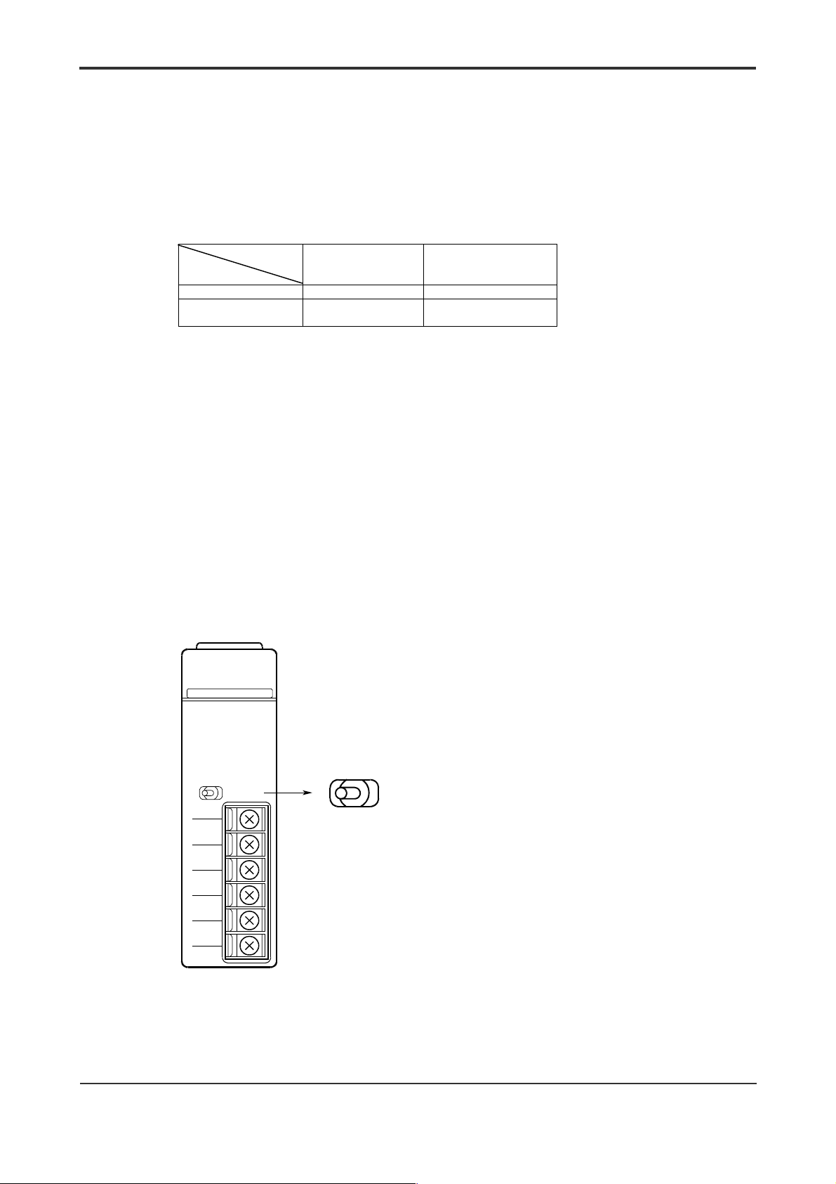
Setting Registers
Depending on the configuration of the external connection, 3 types of modes can be
used in this module, namely 4-wire master station, 4-wire substat ion and 2-wire. If the
register settings corresponding to the three modes are not performed, normal
communication is not possible.
The register settings corresponding to the different modes are performed according to
the details in Table 4.10 using registers 15, 16.
Table 4.10 Setting Registers
Register 15
Register 16
0 Setting not allowed 2-wire
1 4-wire master
0 1
station (default)
Setting of ter m i nati ng Resi stors
Terminating resistors in multi-point connections (including point-to-point connections)
have to be set at stations located on t he respect iv e communication routes.
In the 4-wire system, set the terminating resistor at t he master station and substation n
in Figure 4.3.
For intermediate substation 1 to substation (n-1), remove the t erminating resist or.
Otherwise, normal communications may not be possible.
In the case of F3RS41-0N, the terminating resistor is built-in and is controlled by a
switch. Set the switch to “4-WIRE” for terminal stations and “OFF” for the rest (see
Figure 4.5).
In the 2-wire system, set the terminating resistor at station 1 and station n as in Figure
4.3. Ensure that the terminating resistor is removed from station 2 t o station (n-1).
In the case of F3RS41-0N, the terminating resistor is built-in. Set t he swit ch to “2-WIRE”
for terminal stations and “OFF” for the rest (see Figure 4.5).
4-19
4-wire substation
RDY
RS41-0N
TERMINATOR
2- 4-WIRE
OFF
SD A
SD B
RD A
RD B
SG
SHIELD
RS422
TERMINATOR
2- 4-WIRE
OFF
Figure 4.5 Setting Terminator Switch (For F3RS41-0N Module)
IM 34M6H21-01E 2nd Edition : Aug, 2001-00
Page 51

Device
Protocol Processing
When using multi-point connections on the F3RS41-0N, protocol (communication control
procedure) is essential to prevent line conflicts along the transmission route.
Although FA-M3 provides t he physical int erfaces, it does not support protocol processing
in the system. Therefore, pr otocol control must be described using a BASIC program.
Normally, the polling selection method is used.
FA-M3
4-20
Application
Protocol
Physical interface
Range over which
application
program is used
Remote equipment
Remote equipment
- When transmitting from F3RS41-0N to the remote equipment, the equipment
number must be set to identify the destination.
The equipment number refers to the identification number assigned to the remote
equipment. The remote equipment must be identified in advance according to its
unique identification number by some means.
- The text formats containing the equipment number vary according to t he individual
protocols.
The following example illustrates communication between F3RS41-0N (master station)
and 2 remote equipment (substations).
F3RS41-0N polls the 2 remote equipment for any data to be sent. If there is data to be
sent from the remote equipment, the data is read.
Here, the command for reading the status from the remote equipment is “DS” while the
command for reading the data from the remote equipment is “RD”. An example of the
text format is shown below.
z Text Format
This text format example uses control characters. Control characters are optional.
SOH:start of header
STX:start of text
ETX:End of text
z When F3RS41-0N reads the status of the remote equipment
(command: DS)
F3RS41-0N
- “Status” refers to contents sent from the remote equipment to F3RS41-0N.
“Status” can assume the values of “receive completed”, “receive error” and “send
data exists”. “Send data exists” refers to the flag which indicates whether there is
any data to be sent from the remote equipment to F3RS41-0N.
S
O
Device
H
Command
No.
S
T
X
Remote
equipment
DS
E
T
X
S
O
H
Command
no.
S
T
X
DS Status
E
T
X
IM 34M6H21-01E 2nd Edition : Aug, 2001-00
Page 52

X
4-21
z When F3RS41-0N reads data from the remote equipment
(command: RD)
F3RS41- 0N
F3RS41-0N
- “DATA” refers to contents sent from the remote equipment to F3RS41-0N.
z Timing Chart
Device
S
O
H
Command
S
1
DS
T
X
The program is as shown below
S
O
H
Command
No.
Device
S
T
X
E
DS
T
X
Remote
equipment
S
O
H
No.
Device
S
RS DATA
T
E
T
X
Command
E
T
X
S
S
DS
1
O
T
H
X
Remote equipment 1
Status
S
S
2
O
H
T
X
E
T
X
E
DS
T
X
S
S
O
H
DS
T
2
X
Status E T
S
S
2
O
T
H
X
X
S
O
H
RD
2
E
T
X
Device
S
T
X
RD DATA
Remote equipment
Command
10 DEFINE A-Z
20 SLOT=5:PORT=1
30 ASSIGN RS42=SLOT
40 CONTROL SLOT,PORT,14;7 :! 9600bps
50 CONTROL SLOT,PORT,22;$003 :! Terminator = ”ETX”
60 RESET SLOT,PORT,1 :! Reset buffer
70 ON INT SLOT,PORT GOSUB ENTSTS@ :! Declare interrupt and set branch
points
80 ENABLE INTR SLOT,PORT;“111” :! Enable interrupt
90 MNUMBER$=“01” :! Device number
100 COMMAND$=“DS” :! “DS”; Read Status command
110 GOSUB SND@
120 WAIT
(to be continued on the next page)
E
T
X
IM 34M6H21-01E 2nd Edition : Aug, 2001-00
Page 53

4-22
1000 ENTSTS@ :! Interrupt handling subroutine
1010 STATUS SLOT,PORT,2;IREC :! Interrupt request status
1020 IF IREC=0THEN :! Normal receive?
1030 GOTO ENTDAT@ :! Goto Receive Data
1040 ELSE
1050 DP“Error or break received.”
1060 GOTO RTN@
1070 ENDIF
1080 ENTDAT@
1090 ENTER SLOT,PORT;RCVDAT$
1100 RCVMNUM$=MID$(RCVDAT$,3,2) :! Extract device no.
1110 IF RCVMNUM$ <> MNUMBER$ THEN GOTO RTN@ :! Do not process error device no.
1120 RCVCMD$= MID$(RCVDAT$,7,2) :! Extract command
1130 IF RCVCMD$=“DS”THEN
1140 RCVSTS$=MID$(RCVDAT$,9,1) :! Extract status
1150 RST=VAL(RCVST$) :! Check “send data exists” flag
1160 RST=BINAND(RST,$04) :!
1170 IF RST=4 THEN :!
1180 COMMAND$=“RD” :! “RD”; Read Device Data command
1190 GOSUB SND@
1200 ENDIF
1210 ENDIF
1220 RTN@
1230 ENABLE INTR SLOT,PORT;“111”SND@
1240 RETURN
2000 SND@ : ! Send routine
2010 SNDDAT$=CHR$(01)+MNUMBER$+CHR$(02)+COMMAND$:! Create text ”SOH”
+ ”Device no.” + ”STX” + ”Command”
2020 OUTPUT SLOT,PORT;SNDDAT$
2030 RETURN
3000 END
IM 34M6H21-01E 2nd Edition : Aug, 2001-00
Page 54

5. BASIC Statements and Error Codes
5.1 BASIC Statements
Table 5.1 BASIC Statements
BASIC Statement Functions
ENTER S,P Data input
OUTPUT S,P Data output
TRANSFER S,P Start data input / output
ON EOT S,P Enable program branching on completion of data transf er
OFF EOT S,P Disable program branching on completion of data transfer
ENABLE INTR S,P Mask / unmas k receive interrupt for all ports
ON INT S,P Enable program branching for receive interrupt
OFF INT S,P Disable program branching for receive interrupt
SET TIMEOUT S,P Set the maximum wait time for response from interface
ON TIMEOUT S,P Enable program branching on timeout
OFF TIMEOUT S,P Disable progr am branching on timeout
RESET
HALT S,P Cancels output operation initiated with the TRANSFER statement
STATUS S,P,R Refer to status registers
CONTROL S,P,R Change control registers
S: slot number
P: port number
R: register number
S Module reset … initialization of the communication buffer and
S,P[,0] Port reset … init ialization of the communication buffer and
S,P,1 Buffer reset … initialization of only the communication buffer
Mask / unmask receive interrupt f or specified ports
communication conditions for all ports
communication conditions for spec ified ports
5-1
IM 34M6H21-01E 2nd Edition : Aug, 2001-00
Page 55

5.2 Error Codes
The following table lists the error codes for F3RS22-0N and F3RS41-0N together with a
short description and the possible causes.
Table 5.2 Error Codes
Error
Code
82
Detailed
Error Code
82 Error in function
91 Parameter error - Port number is invalid.
9D ASSIGN
D1 Module not
C1 User buffer
C7 Reset detected - Only the module side detected a power failure and performs a reset start,
D4 *
E1 Self-diagnosed
E2 Module busy - A command other than HALT is executed for the port during TRANSFER.
E6
The contents can be classified by referring to the STATUS register (register number 3)
(see “
Description Possible Causes
specification
statement not
executed
installed
overflow
Parity error - The setting of the parity bit is different at t he sending side and receiving
Framing error - The length of data bit, length of stop bit and the data transfer rate are
Overrun error - Received data overflows the receiving buffer.
Internal buffer
overflow
Character-tocharacter
receiving
interval timeout
Break received
error
Line busy - When CD check is 1 and the monitored time z 0, and CD is not turned off
Timeout
Using Registers” in Section 4.4).
- Cable is not connected.
- An attempt was made to execute a command that is not supported.
- Specification of sl ot number and port number clas hes with other I/O modul es.
- A non-existent register number is specified i n a CONTROL or STATUS
statement.
- ASSIGN statement has not been executed or an invalid slot number was
assigned.
- Module is not connec ted.
- Slot number is inval id.
A data larger than the buffer in BASIC is received.
this leads to inconsistency between the parameters at the module side and
driver side.
side.
different at the s ending and receiving sides.
- Despite continual sending of data, data overflows buffer at BASIC.
- Wit h the character-to-character receiving interval timeout processing set to
Receive Error, data such as the ending character or the number of specified
characters i s not received, resulting in timeout.
- Remote side has sent a break signal
- Error occur s because of self-diagnosis (memory check) in the regul ar state.
within the.preset time period.
- When DR check is 1 and the monitored time
within the preset t ime period.
(1) Receiving side
When waiting to receive in the ENTER statement, the remote side did not
send within the I/O moni tored time period.
(2) Sending side
- CS is OFF.
- When CD check is 1 and the monitored t ime = 0, and CD is ON.
- When DR check is 1 and the monitored time = 0, and DR is OFF.
(caused by faulty c ables or remote equipment)
5-2
z
0, and DR is not turned on
IM 34M6H21-01E 2nd Edition : Aug, 2001-00
Page 56

5.3 Sample Programs
The following shows an example for F3RS22-0N. The program can be used similarly for
F3RS41-0N (point-to-point) by declaring the use of RS41 in the ASSIGN statement.
z Explanations for the sample programs
Send (1) : Send with complete return access using the OUTPUT statement.
Send (2) : Send with proceeding access using the TRANSFER / O N EOT
statements.
Receive (1) : Receive text input with complete return access using only the ENTER
statement.
Receive (2) : Receive text input with interrupt input using ENTER, ON INT / ENABLE
INTER statements.
100 ! F3RS22-0N Example SEND (1)
110 !
120 DIM SENDBUF$256
130 SLOT = 3 : PORT = 2
140 !
150 ! Set communication conditions
160 ASSIGN RS22 = SLOT
170 CONTROL SLOT, PORT, 14; 7
180 CONTROL SLOT, PORT, 13; 2
190 SET TIMEOUT SLOT. PORT; 3000
200 RESET SLOT, PORT, 1
210 !
220 ! Send Data
230 SENDBUF$ = “ABCDEFGhijkl – 0123456789”
240 OUTPUT SLOT, PORT; SENDBUF$
250 END BSC : LIST
100 ! F3RS22-0N Example SEND (2)
110 !
120 DEFINT I
130 DIM SENDBUF$256, OUT$256
140 SLOT = 3 : PORT = 2
150 !
160 ! Set communication conditions
170 ASSIGN RS22 = SLOT
180 CONTROL SLOT, PORT, 14; 7
190 CONTROL SLOT, PORT, 12; 2
200 SET TIMEOUT SLOT. PORT; 3000
210 RESET SLOT, PORT, 1
220 !
230 ! Send Data
240 SENDBUF$ = “ABCDEFGhijkl – 0123456789”
250 OUTPUT OUT$; SENDBUF$
260 ON EOT SLOT, PORT GOSUB EOT@
270 TRANSFER SLOT, PORT FORMAT FROM OUT$
280 !
290 ! Other processing
300 WHILE IEND = 0
310 WAIT
320 END WHILE
330 STOP
5-3
:! Assign card
:! 9600bps
:! Even parity
:! Timeout 3 seconds
:! Reset buffer
:! complete return access
(Type I)
:! Assign card
:! 9600bps
:! 2 stop bits
:! Timeout 3 seconds
:! Reset buffer
:! Output to buffer
:! Interrupt for end of transfer
:! Start (type I)
IM 34M6H21-01E 2nd Edition : Aug, 2001-00
Page 57

340 EOT@ STATUS SLOT, PORT, 4; IOUT
350 IF IOUT <> 0 THEN
360 DISP “Transfer error !!”, HEX$(IOUT)
370 ELSE
380 DISP “Transfer end”
390 ENDIF
400 IEND = 1
410 RETURN
420 END
100 ! F3RS22=0N Example RECEIVE (1)
110 !
120 DIM REC$256
130 SLOT = 3 : PORT = 2
140 !
150 ! Set communication conditions
160 ASSIGN RS22 = SLOT
170 CONTROL SLOT, PORT, 14; 7
180 CONTROL SLOT, PORT, 13; 0
190 CONTROL SLOT, PORT, 12; 2
200 SET TIMEOUT SLOT. PORT; 3000
210 RESET SLOT, PORT, 1
220 !
230 ! Receiving (Complete Return Type)
240 SET STATUS ERR
250 ENTER SLOT, PORT FORMAT; REC$
260 IF ERR = 82 THEN
270 IF ERRCE <> $E6 THEN
280 DISP “error”, HEX$(ERRCE)
290 ELSE
300 GOTO 250
310 ENDIF
320 ELSE
330 DP “time”; TIME$, “receive data”; REC$
340 ENDIF
350 RESET STATUS
360 END
100 ! F3RS22-0N Example RECEIVE (2)
110 !
120 DEFINT I
130 DIM REC$256
140 SLOT = 3 : PORT = 2
150 !
160 ! Set communication conditions
170 ASSIGN RS22 = SLOT
180 CONTROL SLOT, PORT, 14; 7
190 CONTROL SLOT, PORT, 12; 2
200 SET TIMEOUT SLOT. PORT; 3000
210 RESET SLOT, PORT, 1
220 !
230 ! Interrupt Declaration
240 ON INT SLOT, PORT GOSUB REC@
250 ENABLE INTR SLOT, PORT; “111”
260 !
270 WHILE IEND = 0
5-4
:! Interrupt raised because end
of output
:! Assign Card
:! 9600bps
:! No parity
:! 2 stop bits
:! Timeout 3 seconds
:! Reset buffer
:! Receive (Type II)
:! Assign card
:! 9600bps
:! 2 stop bits
:! Timeout 3 seconds
:! Reset buffer
IM 34M6H21-01E 2nd Edition : Aug, 2001-00
Page 58

280 WAIT
290 END WHILE
300 STOP
310 !
320 REC@ ! INTERRUPT INPUT SUBROUTINE
330 STATUS SLOT, PORT, 2; IREC
340 IF IREC = 0 THEN
350 ENTER SLOT, PORT FORMAT; REC$
360 DP “time”; TIME$, “receive data”; REC$
370 ELSE
380 DISP “error or break received”
390 ENDIF
400 ENABLE INTR SLOT, PORT; “111”
410 IEND = 1
420 RETURN
430 END
5-5
:! Interrupt branch condition
:! Normal receive?
:! Receive (type II)
IM 34M6H21-01E 2nd Edition : Aug, 2001-00
Page 59

Blank Page
Page 60

Appx.1-1
Appendix 1. Signal Description and
Direction of Signal Lines
(RS-232-C)
The following figure and table describe the RS-232-C signals and the signal directions
for the F3RS22-0N module.
The selection of the direction of signal lines (only for those that are selectable) is
performed with software setting.
In the following figure, signal lines between ER to CD (inclusive) are control lines w hilst
SD and RD are data lines.
F3RS22-0N
CS (clear to send…ready to receive)
Figure appx. 1 RS-232-C Signals
Table appx. 1 Direction of RS-232-C Signal Lines
Pin Number
F3RS22-0N
3 SD Send Data Output
2 RD Receive Data Input
7 RS Request to
8 CS Clear to Send Input 9 Signal from the remote side granting permi ssion
6 DR Dataset Ready Input 9 Us ed to check whether the remote side can
5 SG Signal Ground
1 CD Data Carrier
4 ER Data Terminal
Mnemonic Signal Name
Send
Detect
Ready
ER (FA-M3 ready)
DR (destination ready)
RS (request to send…ready to receive?)
CD (data carrier detection)
SD (send data)
RD (receive data)
Input
/Output
Output
Input 9 If this signal is not on, a carri er wave is not
Output
Signal
Monitoring
Used when sending data to the remote s ide.
(1) Always ON (default ).
(2) ON only during sending.
to send.
Cannot send if this signal is not ON.
transmit.
(1) Send regardless of the state of DR (default).
(2) Send only when DR is ON.
received.
Sending may proceed as follows:
(1) Send regardless of the state of CD (default)
(2) Send only when CD is OFF.
( 1) Turns on at power-on and s tays on (default).
(2) Can be turned on or off using software.
Remote
equipment
computer,
modem, etc.
Function
IM 34M6H21-01E 2nd Edition : Aug, 2001-00
Page 61

Appendix 2. Data Transmission
Start-Stop Synchronous Transmission
The F3RS22-0N and F3RS41-0N modules transmits using a start-stop synchronous
mode.
When a character is transmitted in start-stop synchronization, a start bit is first
transmitted, followed by the character bits (7 t o 8 bits) in descending sequence, the
parity bit and the stop bit(s). The start bit, p arity bit and stop bit(s) are automatically
inserted by the module and are transparent to the user.
The transfer data rate, data bit length and ot her communication parameters are set
using software.
Appx.2-1
Line idle
1
0
LSB, Least signifi c ant bit
Start bit
z Text
1 character
Character data
(7 to 8 bits)
Parity bit
Figure appx. 2 Start-Stop Synchronous Transmission
Odd, even or
unused
Stop bit
1
1.5
2
Line returns to idle state
(dotted line) or carries
the start bit of the next
character (solid line)
Transmission data usually consists of multiple characters terminated by a terminator
(ending character), known as text, and recognized by the user as a piece of dat a. The
maximum length of text data is 1024 bytes.
1 character Terminator
CR
A B C D
LF
1 text data
Figure appx.3 Example of One Character
IM 34M6H21-01E 2nd Edition : Aug, 2001-00
Page 62

Appendix 3. ASCII Codes
b6 0 0 0 0 1 1 1 1
Bit
b3 b2 b1 b
0 0 0 0 0 NUL DLE SP 0 @ P ‘ p
0 0 0 1 1 SOH DC1 ! 1 A Q a q
0 0 1 0 2 STX DC2 " 2 B R b r
0 0 1 1 3 ETX DC3 # 3 C S c s
0 1 0 0 4 EOT DC4 $ 4 D T d t
0 1 0 1 5 ENQ NAK % 5 E U e u
0 1 1 0 6 ACK SYN & 6 F V f v
0 1 1 1 7 BEL ETB ’ 7 G W g w
1 0 0 0 8 BS CAN ( 8 H X h x
1 0 0 1 9 HT EM ) 9 I Y i y
1 0 1 0 A LF SUB * : J Z j z
1 0 1 1 B VT ESC + ; K [ k {
1 1 0 0 C FF FS , < L ¥ l |
1 1 0 1 D CR GS - = M ] m }
1 1 1 0 E SO RS . > N ^ n ~
1 1 1 1 F SI US / ? O _ o DEL
Control codes Character codes
b5 0 0 1 1 0 0 1 1
order
0
Low order
b4
High-
0 1 0 1 0 1 0 1
0 1 2 3 4 5 6 7
Appx.3-1
IM 34M6H21-01E 2nd Edition : Aug, 2001-00
Page 63

Appx.3-2
Blank Page
IM 34M6H21-01E 2nd Edition : Aug, 2001-00
Page 64

Revision Information
Document Name : Serial Communication Modules
Document No. : IM 34M6H21-01E
Edition Date Revised Item
1st Dec, 1998 New Publication
2nd Aug, 2001 Addition of explanations on support of CE Mark; Correction of typographical errors
i
Written by Product Marketing Department, IT Controller Center.
Yokogawa Electric Corporation
Published by Yokogawa Electric Corporation
2-9-32 Nakacho, Musashino-shi, Tokyo, 180-8750, JAPAN
Printed by Yokogawa Graphic Arts Co., Ltd.
IM 34M6H21-01E 2nd Edition : Aug, 2001-00
Page 65

Blank Page
 Loading...