

Page 1

Technical
Information
TI 34M06T02-02E
Ubuntu Image for F3RP70 User’s Guide
Yokogawa Electric Corporation
Mar. 2021 2nd Edition (YK)
TI 34M06T02-02E
Page 2

Content-1
Ubuntu Image for F3RP70 User’s Guide
TI 34M06T02-02E
2nd Edition
Contents
Introduction
1 F3RP70-2L
1.1 Overview ................................................................................................ 1-1
1.2 Ubuntu image ........................................................................................ 1-1
2 Writing the Ubuntu image file to the SD memory
card and startup
2.1 Procedure overview .............................................................................. 2-2
2.2 The SD memory card for starting ........................................................ 2-3
2.2.1 Specifications of the Ubunut image ........................................................... 2-3
2.2.2 User settings ................................................................................................. 2-5
2.2.3 Network settings ........................................................................................... 2-5
2.3 Procedure for writing to the SD memory card ...................................... 2-7
2.3.1 Environment installation ............................................................................... 2-7
2.3.2 How to write to the SD memory card ....................................................... 2-11
2.4 Starting from the SD memory card ...................................................... 2-14
2.4.1 Procedure of startup .................................................................................. 2-14
2.4.2 Procedure of log in to Ubutu ..................................................................... 2-14
2.4.3 Enable the sudo command ........................................................................ 2-21
3 e-RT3 IO module configuration service
3.1 Functional overview ............................................................................. 3-2
3.2 Usage ..................................................................................................... 3-4
3.2.1 Setting file ..................................................................................................... 3-4
3.2.2 Working with the daemon ............................................................................ 3-4
3.3 Setting file in detail .............................................................................. 3-6
3.3.1 Digital input module ..................................................................................... 3-6
3.3.2 Digital output module ................................................................................... 3-7
3.3.3 Analog input module ..................................................................................... 3-8
3.3.4 Analog output module ................................................................................ 3-10
3.3.5 High-speed data acquisition module ........................................................ 3-11
3.3.6 Temperature monitor module .................................................................... 3-14
TI 34M06T02-02E 2021.03.31-00
Page 3

4 F3HA12 data acquisition service
4.1 Functional overview ............................................................................. 4-1
4.2 Usage ..................................................................................................... 4-2
4.2.1 Working with the daemon ............................................................................ 4-2
4.2.2 Data acquisition ............................................................................................ 4-3
4.3 API .......................................................................................................... 4-5
5 Application development with Python
5.1 Development method ........................................................................... 5-2
5.2 Remote development with Visual Studio Code ................................. 5-3
5.2.1 Overview ........................................................................................................ 5-3
5.2.2 Environment creation procedure ................................................................. 5-4
5.2.3 Usage ........................................................................................................... 5-16
5.3 Remote development with Jupyter Notebook ................................. 5-22
Content-2
5.3.1 Overview ...................................................................................................... 5-22
5.3.2 Environment creation procedure ............................................................... 5-23
5.3.3 Usage ........................................................................................................... 5-24
5.4 How to access the IOModule ............................................................ 5-30
5.4.1 Input output data of IO module ................................................................. 5-30
5.4.2 Calling C/C++ library functions from Python .......................................... 5-31
5.5 Sample program .................................................................................. 5-41
6 Application development with C/C++
6.1 Host development with F3RP70-2L .................................................... 6-1
6.1.1 Usage ............................................................................................................. 6-1
6.1.2 Using the e-RT3-specific API functions ..................................................... 6-9
7 Overlay Filesystem
7.1 Overview ................................................................................................ 7-2
7.1.1 OverlayFS overview ...................................................................................... 7-2
7.1.2 Overview of procedures ............................................................................... 7-2
7.2 Description of Overlay FS .................................................................... 7-3
7.3 Enter settings ........................................................................................ 7-4
7.3.1 Preparing the operating environment ......................................................... 7-4
7.3.2 Configuring OverlayFS ................................................................................. 7-5
7.3.3 Clearing OverlayFS settings ........................................................................ 7-5
7.4 Usage precautions ................................................................................ 7-7
TI 34M06T02-02E 2021.03.31-00
Page 4

Appendix1 I/O Module Access Library
A1.1 List of APIs ......................................................................................... A1-1
A1.2 List of API error codes ....................................................................... A1-2
A1.3 Receiving interrupts and alarms ...................................................... A1-4
A1.4 How to receive signals (inter-process communication) ............... A1-9
A1.5 API reference .................................................................................... A1-12
A1.5.1 I/O module ................................................................................................ A1-12
A1.5.2 CPU module .............................................................................................. A1-24
A1.5.3 PLC device ................................................................................................ A1-31
A1.5.4 System administration ............................................................................ A1-43
A1.5.5 RAS ............................................................................................................ A1-48
A1.5.6 WDT ........................................................................................................... A1-51
Appendix2 Web Maintenance Tool
A2.1 Before Use .......................................................................................... A2-1
Content-3
A2.1.1 Overview ..................................................................................................... A2-1
A2.1.2 Operating environment ............................................................................. A2-1
A2.1.3 Setup and start-up ..................................................................................... A2-2
A2.2 Screen configuration and basic functions ...................................... A2-5
A2.2.1 List of functions ......................................................................................... A2-5
A2.2.2 Portal screen (Start-up screen) ............................................................... A2-7
A2.2.3 Main screen ................................................................................................ A2-8
A2.2.4 Changing languages .................................................................................. A2-9
A2.3 Device monitor (Module selection screen) ................................... A2-10
A2.3.1 CPU module monitor screen ................................................................... A2-12
A2.3.2 I/O device monitor screen ...................................................................... A2-17
A2.3.3 Using and installing comment file ......................................................... A2-21
A2.4 CPU settings ..................................................................................... A2-23
A2.4.1 CPU settings (Top/Login) screen .......................................................... A2-23
A2.4.2 User management screen ....................................................................... A2-24
A2.4.3 Calendar / Time settings screen ............................................................ A2-25
A2.4.4 Device settings screen ............................................................................ A2-26
A2.4.5 Operation settings screen ....................................................................... A2-29
A2.5 Manual display ................................................................................. A2-31
A2.5.1 Installing manual files ............................................................................. A2-32
A2.5.2 Displaying the manuals ........................................................................... A2-33
Revision Information ................................................................................. Rev-1
TI 34M06T02-02E 2021.03.31-00
Page 5

A
Introduction
Overview
This manual describes how to use the Ubuntu image, which is provided for the OSfree CPU module.
The OS-free CPU module is e-RT3 CPU module that incorporates only a boot
loader. Users can develop their own system, while it takes time and effort to gain
knowledge for using the module.
Use of the Ubuntu image allows you to easily take advantage of a system with a
combined set of some open-source software.
Other Instruction Manuals
In addition to this manual, refer to the following manuals.
Product manuals
- e-RT3 CPU Module (F3RP7) Hardware Manual (IM 34M06M52-01E)
- e-RT3 CPU Module (SFRD2) BSP Common Function Manual (IM 34M06M5202E)
- e-RT3 OS-free CPU Module Startup Manual (IM 34M06M52-25E)
Related manuals
- Hardware Manual (IM 34M06C11-01E)
- Analog Input Modules (IM 34M06H11-02E)
- Analog Output Module (IM 34M06H11-03E)
- High-speed Data Acquisition Module (F3HA06-1R, F3HA12-1R) (IM 34M06G0202E)
- Temperature Monitoring Module (IM 34M06H63-01E)
*This manual contains current information as of March 2021.
The features or specifications of the product may be subject to change in the future.
i
ll Rights Reserved. Copyright © 2020, Yokogawa Electric Corporation TI 34M06T02-02E Mar. 31, 2021-00
Page 6

1. F3RP70-2L
1.1 Overview
F3RP70-2L is one of the models in the e-RT3 CPU modules. It incorporates a
boot loader only and allows its users to construct a flexible system, including
the operating system.
After F3RP70-2L is turned on, the boot loader starts its operation and
initializes hardware and e-RT3/FA-M3 modules. The boot loader of F3RP70-2L
provides the features of starting the OS according to the setup parameters
and of self-diagnosing the module, based on the state of the MODE switch.
1.2 Ubuntu image
Ubuntu image file to be installed in F3RP70-2L for easy use is provided. The
Ubuntu image file available on the e-RT3 website allows you to start
development early.
You will store this provided Ubuntu image file in an SD memory card before
using the image. To use it, follow the procedure in the next chapter to write
the operating system into the SD memory card and then insert the card into
F3RP70-2L.
1-1
TI 34M06T02-02E Mar. 31, 2021-00
Page 7

2-1
2. Writing the Ubuntu image file to the SD memory card and startup
This chapter describes the procedure for writing the Ubuntu image file to an
SD memory card and startup.
TI 34M06T02-02E Mar. 31, 2021-00
Page 8

2.1 Procedure overview
This section provides an overview of the procedure for writing the Ubuntu
image file to an SD memory card and startup.
For details on the procedure, refer to “2.3 Procedure for writing to the SD
memory card” and “2.4 Starting from the SD memory card” of this manual.
Writing to an SD memory card
Use the following procedure to write the Ubuntu image file to an SD memory card:
- Download the Ubuntu image file from the Yokogawa website.
- Let your PC recognize an SD memory card.
- Use a tool for writing disk images to write the Ubuntu image file to the SD
memory card.
What you need
You need to have the following items for the write to the SD memory card:
- PC that supports SD memory cards
- SD memory card (SDHC card: 4 to 32 GB)
- Tool for writing disk images
- Ubuntu image file
You need to have the following items for starting Ubuntu from SD memory card:
- PC
- Terminal software (ex. PuTTY, tera term or.)
- RS-232-C conversion cable (KM72-2N) or Ethernet cable
2-2
TI 34M06T02-02E Mar. 31, 2021-00
Page 9
2.2 The SD memory card for starting
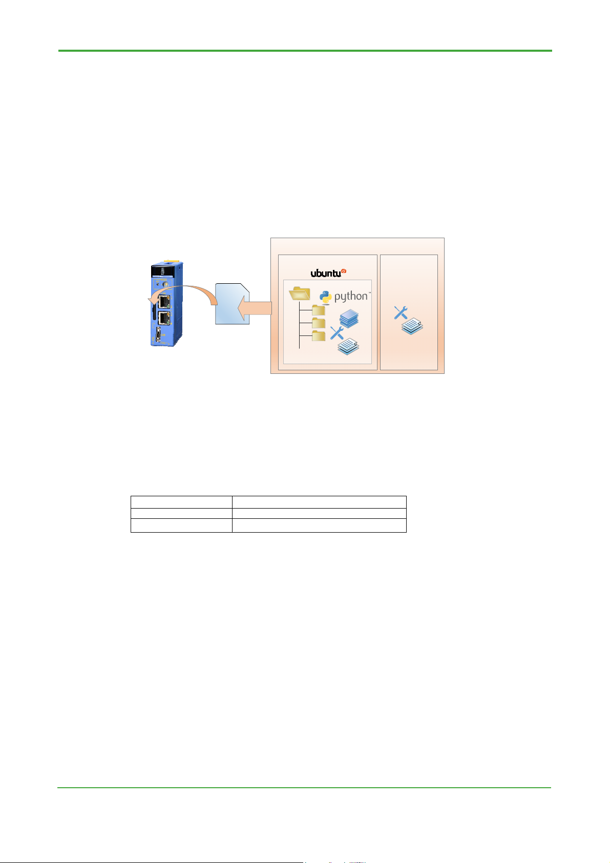
This section describes the SD memory card image you create in this chapter.
The SD memory card image consists of all copied files of the Ubuntu
operating system (OS) that runs on F3RP70-2L and a collection of setting files
necessary for starting the OS. The OS section contains the OS settings as well
as the stored files.
By inserting the SD memory card that has the Ubuntu image into an SD
memory card slot of F3RP70-2L, you can start Ubuntu with F3RP70-2Lsuitable settings and necessary libraries and packages installed in it.
SD memory card image
F3RP70
Operating system
SD memory
card
...
Collection of
setting files for
starting
F3RP70
2-3
Operating system
Setting files
Libraries
Created files, etc.
+
Collection of setting files for
starting F3RP70
Figure 2.1 Description of the SD memory card for starting
2.2.1 Specifications of the Ubuntu image
Revision
The revision of the Ubuntu image is confirmed in the file below.
Revison File
R.1.1.1 None
R.1.2.1 or later /usr/local/etc/sfrd14-release
OS
Ubuntu18.04LTS, GNU/Linux4.14LTS+PREEMPT_RT is started.
With the following command, you can see kernel configuration of the Ubuntu image.
$ zcat /proc/config.gz
Same information is described in the file /boot/config-xxx-ert3xlnx (xxx is version of
kernel).
Ubuntu development package
Python 3 and the build-essential toolchain are available as a program development
environment.
TI 34M06T02-02E Mar. 31, 2021-00
Page 10

2-4
e-RT3 module access
It provides the API functions for working with various e-RT3 I/O modules and e-RT3
CPU and sequence CPU modules in the multi-CPU configuration, together with the
signal notification feature used for synchronization operations between CPU
modules.
Note
For details on the API functions for e-RT3 I/O module access, refer to “Appendix1
I/O Module Access Library” of this document.
PLC device access
PLC device access is a feature to emulate the structure of data in a sequence CPU
module. It provides a service for connecting programmable indicators through PC
link commands (specifications from Yokogawa) and a mechanism for shared devices
in the multi-CPU configuration.
It also offers the API functions for working with these PLC devices.
Note
For details on the API functions for e-RT3 I/O module access, refer to “Appendix1
I/O Module Access Library” of this document.
External equipment communication service
It provides a communication feature with external equipment, such as indicators and
PCs, via the command interface. With this service, you can monitor and configure
CPU devices and work with programs in sequence CPU modules to operate or stop
them via external equipment.
RAS
It provides the API functions for examining or monitoring failures in systems and a
mechanism for receiving alarms when a failure occurs. You can receive alarms from
the momentary power failure detection feature for power supply voltage or about
abnormal temperatures of CPU modules.
Note
For details on the features above, refer to “e-RT3 CPU Module (SFRD2) BSP
Common Function Manual” (IM 34M06M52-02E).
Web Maintenance Tool
This tool offers features for monitoring and configuring I/O modules and internal
TI 34M06T02-02E Mar. 31, 2021-00
Page 11

2-5
parameters of the system provided by the Ubuntu image.
It is available on a Web browser, such as Google Chrome. Therefore, end users
who do not have any development environment and engineers in charge of
maintenance or launching can easily work on their configuration or maintenance
tasks on the Web browser regardless of their PC environment.
Note
For details on the features above, refer to “Appendix2 Web Maintenance Tool” of
this document.
Python 3 related packages
The Python-related packages listed in the table below are installed.
If necessary, use the apt command or the pip3 command to add or remove a
package.
No. Class Package
1 Machine learning scikit-learn
2 Numerical processing numpy
3 Numerical processing pandas
4 Numerical processing scipy
5 Graph drawing matplotlib
6 Communication pymodbus
7 Development environment jupyter-notebook
Development environment ptvsd
2.2.2 User settings
The Ubuntu OS provided by this image file has the users below.
If necessary, change the password or add or remove a user.
Root user
User name: root
Password: root_ert3
Ordinary user
User name: ert3
Password: user_ert3
2.2.3 Network settings
The Ubuntu OS provided by this image file has the network settings below.
Change them to suit the user's environment. The Ubuntu OS starts with the new
settings if you reboot it after modifying the setting file.
TI 34M06T02-02E Mar. 31, 2021-00
Page 12

2-6
eth0 (LAN port 1)
IP address: 192.168.3.72
Network mask: 255.255.255.0
Setting file:
/etc/systemd/network/10-eth0.network
A setting example for stable IP address is described below. You should modify
“Address”, “Gateway” and “Destination” for your environment.
[Network]
Address=192.168.3.72/24
[Route]
Gateway=192.168.3.1
Destination=192.168.3.0/24
eth1 (LAN port 2)
IP address: get from DHCP
Network mask: get from DHCP
Setting file:
/etc/systemd/network/20-eth1.network
TI 34M06T02-02E Mar. 31, 2021-00
Page 13

2.3 Procedure for writing to the SD memory card
This section describes the detailed procedure for writing the Ubuntu image
file to the SD memory card.
Note
In this procedure, all components (including your settings and applications) in SD
memory card are overwrote. When you use new version of Ubuntu image, you shall
re-install your settings and applications in the new Ubuntu.
2.3.1 Environment installation
This subsection describes the environment necessary for the tasks in this section.
2-7
PC
You need to have a PC that meets the following criteria:
- It supports SD memory cards.
You need to use a PC with a built-in SD memory card drive, or have an external
SD memory card reader and connect it to your PC.
- It supports a given tool for writing disk images.
SD memory card
F3RP70-2L supports an SDHC memory card with a capacity of 4 to 32 GB.
We recommend that you use a card with a higher program/erase cycle, such as an
SLC- or MLC-type card.
Ubuntu image file
You download it from our website “Yokogawa Partner Portal”.
Access the following URL and download “OS image file for OS-free CPU Module”
URL: https://partner.yokogawa.com/global/itc/index.htm
Tool for writing disk image files
You can have any tool for writing disk image files.
This manual shows a procedure for Rawrite32, free software for Windows.
How to install
1. Access the following URL and click the [Download] link at the top of the
Rawrite32 website.
TI 34M06T02-02E Mar. 31, 2021-00
Page 14

2-8
https://www.netbsd.org/~martin/rawrite32/index.html
Figure 2.2 Download link for Rawrite32
2. Click the [rw32-setup-1.0.7.0.exe] button to download the file.
Figure 2.3 Selecting the file for Rawrite32
3. Open the downloaded file to start the installer.
If you see a dialog box saying “Do you want to allow this app to make changes
to your device?” instead of the installer being started, click [Yes]. The installer is
then started.
4. Without making particular changes to the settings, click the [Install] button. The
installation is now started.
TI 34M06T02-02E Mar. 31, 2021-00
Page 15

2-9
Figure 2.4 Rawrite32 setup dialog box
5. Once the installation is complete, click the [Finish] button to exit the installer.
Figure 2.5 Complete Rawrite32 installation screen
Note
The following PC environment was used to check the procedure described in this
section.
- OS: Windows 10 Enterprise (64-bit version)
TI 34M06T02-02E Mar. 31, 2021-00
Page 16

- SD memory card support: Built-in SD memory card drive
The following SD memory card is available:
- SDHC memory card (4 to 32 GB)
The size of the Ubuntu image file for use ranges from 1 to 2 GB. Choose the
capacity of your card by considering the fact that data is also stored in the SD card
while you are using F3RP70-2L.
For details on the recommended standard and the use of the SD memory card slot
of e-RT3, refer to “4.5 SD memory card” of “e-RT3 CPU Module (F3RP7)
Hardware Manual” (IM 34M06M52-01E).
In the procedure described in this section, you do not have to uncompress the
downloaded file.
You cannot use a general operation for pasting a file to write the SD memory card
image to the SD card. Make sure that you have a tool for writing disk image.
2-10
TI 34M06T02-02E Mar. 31, 2021-00
Page 17
2.3.2 How to write to the SD memory card
This subsection details the writing procedure.
Let your PC recognize an SD memory card
Before starting Rawrite32, SD memory card have to be recognized by PC.
Start Rawrite32
If you see a dialog box saying “Do you want to allow this app to make changes to
your device?” instead of Rawrite32 being started, click [Yes]. Rawrite32 is then
started.
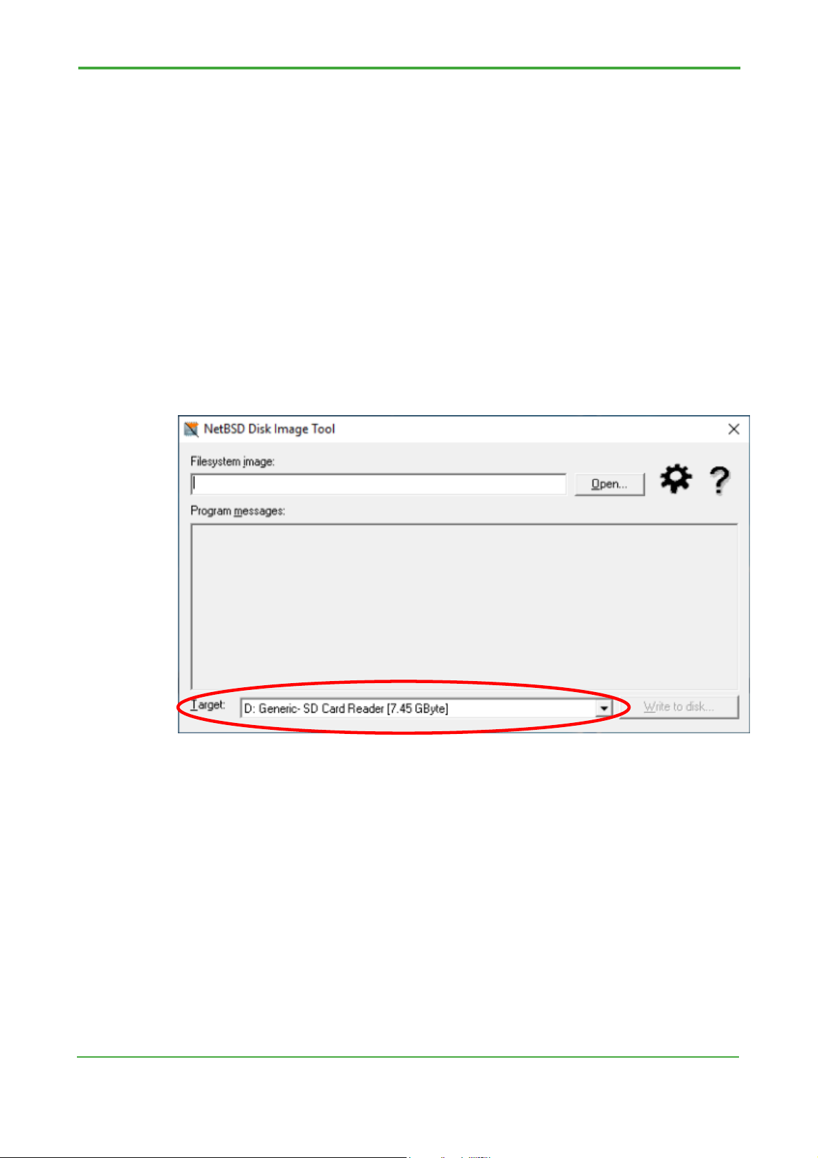
In the startup screen, check that [Target] is set to the location of the SD memory
card drive and the capacity of the card is indicated in [ ]. In the following example, a
32-GB SD memory card is used.
2-11
Figure 2.6 Rawrite32 startup screen
Select the Ubuntu image file to be written
At the top right of the screen, click the [Open...] button and select the compressed
Ubuntu image file you downloaded. Hash values are then calculated and displayed
in the [Program messages] section in the middle of the screen.
The [Write to disk...] button is also activated at the bottom right of the screen so that
you can click it.
TI 34M06T02-02E Mar. 31, 2021-00
Page 18

2-12
Figure 2.7 Complete Ubuntu image loading screen
Write the image
At the bottom right of the screen, click the [Write to disk...] button to open the dialog
box as shown in the figure below. Click the [Yes] button to start writing to the SD
memory card.
Figure 2.8 Write confirmation screen
TI 34M06T02-02E Mar. 31, 2021-00
Page 19
2-13
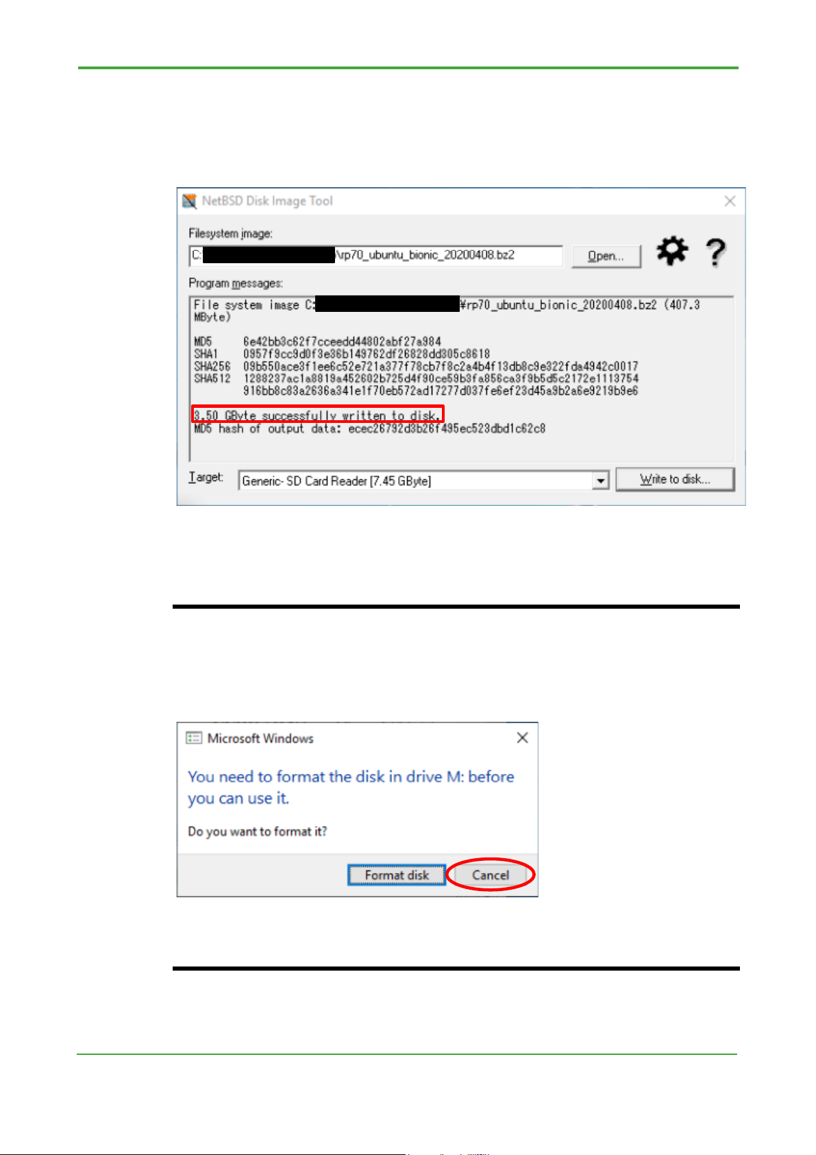
Confirm the completion of writing
The writing is complete when you see the message saying “successfully written to
disk” in the [Program messages] section, as shown in the figure below. At the top
right of the screen, click the [x] button to exit Rawrite32.
Figure 2.9 Writing completed screen
Note
When you perform the procedure in this section, all the data in the SD memory card
is overwritten. Use a blank SD memory card, or back up the data beforehand.
After the writing is completed, you sometimes see a dialog box that request you to
format the SD memory card. If this happens, cancel the format.
This is because the written image file contains a Linux file system (ext4) that cannot
be read by Windows. If you format the card accidentally, follow the procedure in this
subsection to write to the SD card again.
TI 34M06T02-02E Mar. 31, 2021-00
Page 20

2.4 Starting from the SD memory card
This section describes how to start the Ubuntu image file written to the SD
memory card.
2.4.1 Procedure of startup
This subsection details the startup procedure.
Insert the SD memory card
Insert the SD memory card into SD slot 1 or 2 of F3RP70.
If two memory cards are inserted at the same time, the image in slot 1 is used in
preference to the one in the other slot.
When you use SD slot 2, you have to set “rootdev” environment variable of u-boot
to ”/dev/mmcblk1p2”. And when you use SD slot 1, you have to remove “rootdev”
environment variables.
Example for setting “rootdev” to “/dev/mmcblk1p2”
f3rp7x> setenv rootdev /dev/mmcblk1p2
2-14
f3rp7x> saveenv
Example for removing value of “rootdev”
f3rp7x> setenv rootdev
f3rp7x> saveenv
Note
For details on environment variable of u-boot, refer to “e-RT3 OS-free CPU Module
Startup Manual” (IM 34M06M52-25E).
Start the system
With the MODE switch set to 0, turn on the power.
2.4.2 Procedure of log in to Ubuntu
This subsection details log-in procedure.
What you need
You need to have the following items for log-in to Ubuntu using serial console:
- PC that is installed terminal software
- RS-232-C conversion cable (KM72-2N)
- USB-serial converter (when your pc doesn’t have seral port)
TI 34M06T02-02E Mar. 31, 2021-00
Page 21

2-15
You need to have the following items for log-in to Ubuntu using SSH connection:
- PC that is installed terminal software
- Ethernet cable
Construction of devices
Figure 2.10 shows the construction of devices.
Log in to the Ubuntu through a serial console connection using the COM port at the
front of the CPU module or from an SSH terminal using the LAN port. In this section,
log in using the default value of eth0 (LAN port 1) shown in section 2.2.3 of this
document, so connect the ethernet cable to LAN port1 on the upper front of the
F3RP70-2L.
F3RP70
Local machine e-RT3
Figure 2.10 Construction of devices
Installing a terminal software
A terminal software, such as “Putty” or “Tera term”, is needed when you log in to the
Ubuntu. This subsection describes installing procedure of “PuTTY” as an example.
1. Access the following URL and click the [here] in [Download PuTTY] contents.
Figure 2,11 Top page of PuTTY web site
2. Download the installer that matches your PC from the “Package files”.In this
document, we will explain using the 64-bit version of “MSI (‘Windows Installer’)”
TI 34M06T02-02E Mar. 31, 2021-00
Page 22

2-16
Figure 2.12 Download installer
3. Open the downloaded file to start the installer. When the following dialog is
shown, Click the “Run”.
Figure 2.13 Security dialog
4. Click the “Next”.
Figure 2.14 PuTTY installer
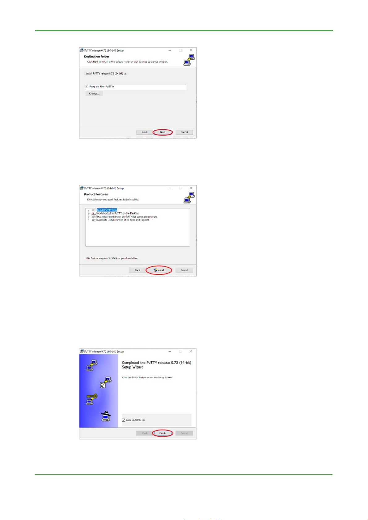
5. Specify the install location. In this document, do not change the destination
folder and click “Next”.
TI 34M06T02-02E Mar. 31, 2021-00
Page 23
2-17
Figure 2.15 Specify the install location
6. Click “Next”.
Figure 2.16 Selection of install components
7. When User Account Control dialg is displayed, click “Yes”.
8. Click “Finish” in the dialog of install completion. And then installation of “PuTTY”
is completed.
Figure 2.17 Dialog of install completion
Log in to Ubuntu using serial console
TI 34M06T02-02E Mar. 31, 2021-00
Page 24
2-18
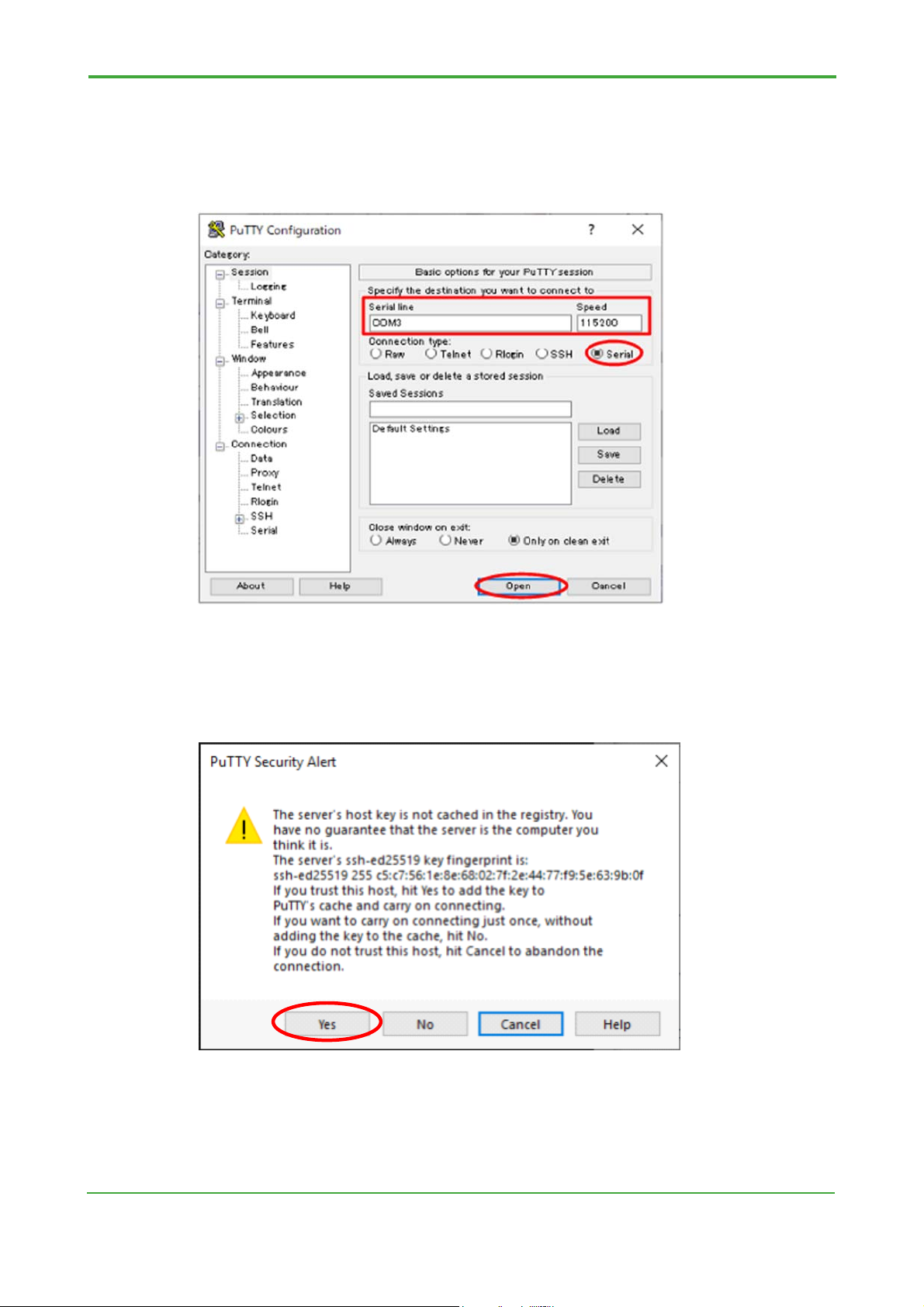
1. Start PuTTY and set “Connection type” to “Serial. And then set some items as
follows and click “Open”
Serial-line: device of serial port
Speed: 115200
Figure 2.18 PuTTY setting
2. When connection to F3RP70-2L for the first time, the PuTTY Security Alert
dialog is displayed. Click “Yes” to continue the connection.
Figure 2.19 PuTTY Security Alert dialog
3. Turn on F3RP70-2L.
4. Login prompt is displayed on the console after boot sequence. Log in using the
TI 34M06T02-02E Mar. 31, 2021-00
Page 25

2-19
user account you have set up.
Figure 2.20 Login prompt of serial console
Log in to Ubuntu using SSH connection
1. Turn on F3RP70-2L.
2. Set an IP address of your PC to “192.168.3.□□”
3. Start PuTTY and set “Connection type” to “SSH”. And then set some items as
follows and click “Open”
Host Name (or IP address): 192.168.3.72
Port: 22
Figure 2.21 SSH setting of PuTTY
TI 34M06T02-02E Mar. 31, 2021-00
Page 26
2-20
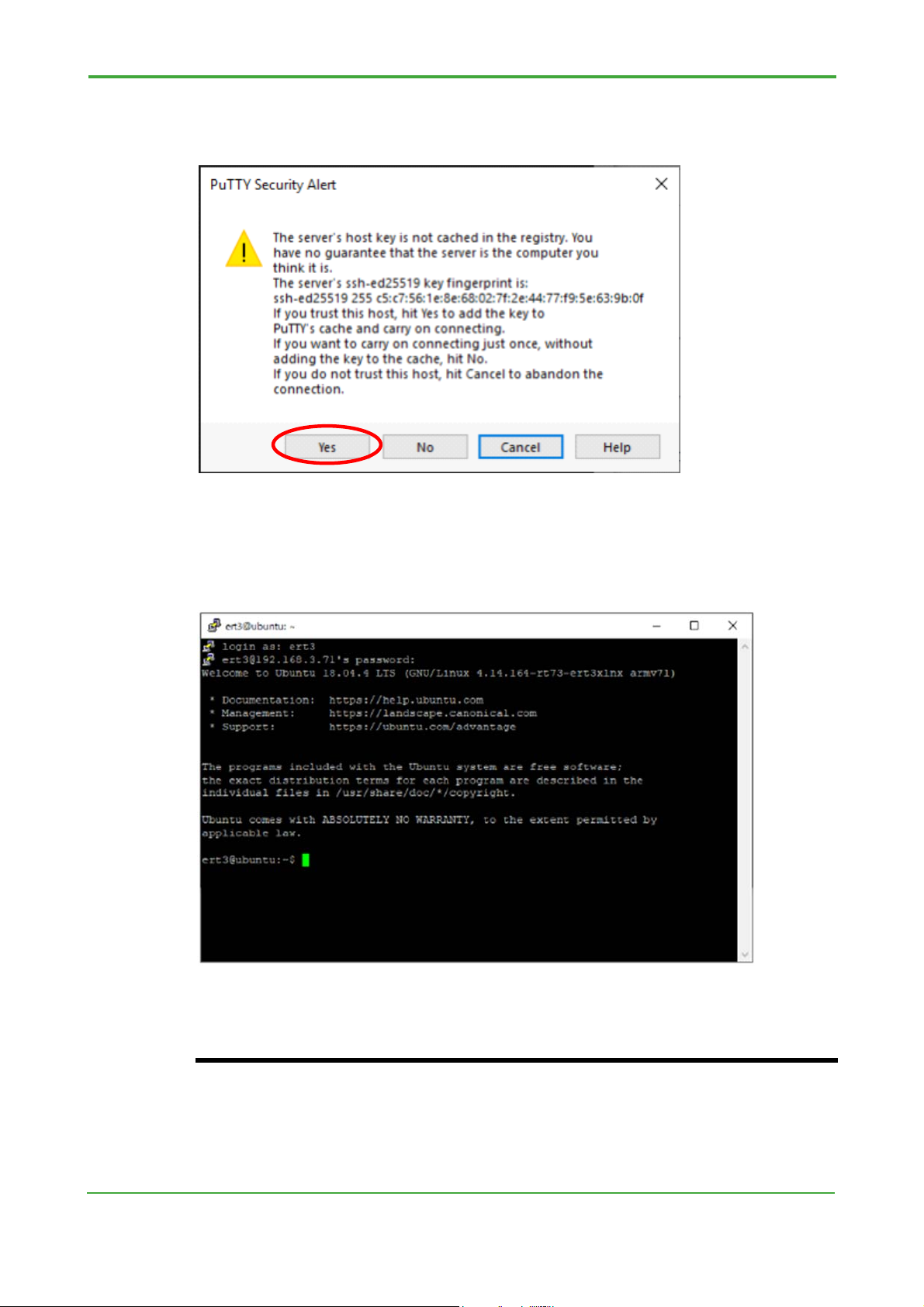
4. When connection to F3RP70-2L for the first time, the PuTTY Security Alert
dialog is displayed. Click “Yes” to continue the connection.
Figure 2.22 PuTTY Security Alert dialog
5. Login prompt is displayed on the console. Log in using the user account you
have set up.
Figure 2.23 Login prompt of SSH connection
Note
If you change the settings of your computer's network adapter according to the
instructions in this manual, you may not be able to connect to the Internet using that
adapter.
Connect the F3RP70-2L to a port that is not normally used for internet connection or
restore the settings after the connection is completed.
TI 34M06T02-02E Mar. 31, 2021-00
Page 27

When you want to connect to SSH, please do after starting F3RP70-2L. Immediately
after starting, the SSH server may not start and connection may fail.
With the initial settings downloaded Ubuntu image from the Yokogawa web site, you
cannot use the SSH connection to log in with the root user account. Please log in
with an ordinally user account.
For the default value of the user account, see "2.2.2 User setting" in this manual.
2.4.3. Enable the sudo command
In this Ubuntu image, the sudo command cannot be used by general users in the
default state. If you want to use commands that require root privileges, enter the
settings in this section to enable them. The following are some examples of when
the sudo command is not available.
# Operation with general user username
$ sudo ls -a /root
[sudo] password for username: # Enter Password
username is not in the sudoers file. This incident will be reported.
2-21
Enabling the sudo command
1. Confirm the group of the user for whom you want to enable the sudo command.
If sudo is not included in the group, the sudo command is not available.
# For general user username
$ groups username
username : username # User name: Group
2. Since the operation is performed with root privileges, switch to the root account.
$ su
Password: # Enter root Password
root@ubuntu:/home/username#
3. Add the user for whom to enable the sudo command to the sudo group.
# gpasswd -a username sudo
Adding user username to group sudo
4. Confirm that sudo was added by checking the user's group in the same
procedure as in 1. Once added, log out of the root account. The settings will be
reflected when you log back in, so also log out of the general user account.
# groups username
username : username sudo # User name: Group
# exit
TI 34M06T02-02E Mar. 31, 2021-00
Page 28

2-22
exit
$ exit
logout
5. When you log in for the first time with the account that you added to the sudo
group, the following appears, indicating that the sudo command is enabled.
To run a command as administrator (user "root"), use "sudo <command>".
See "man sudo_root" for details.
username@ubuntu:~$
6. Confirm that the sudo command is received.
$sudo ls -a /root
[sudo] password for username: # Enter Password
. .. .bash_history .bashrc .cache .gnupg .profile
username@ubuntu:~$
Disabling the sudo command
To disable the sudo command, follow the steps below. Cancel membership in the
sudo group; the opposite of when you enabled it.
1. Just as with enabling the sudo command, you need root privileges, so switch to
the root account as you did in enable step 2.
2. Remove the user for whom you want to disable the sudo command from the
sudo group.
# gpasswd -d username sudo
Removing user username from group sudo
3. Using the same procedure as in enabling 1., check the user’s group. Once you
have confirmed that sudo has been deleted, log out of the root account. The
settings will be reflected when you log back in, so also log out of the general
user account.
# groups username
username : username
# exit
exit
$ exit
logout
4. When you login to the account from which you canceled sudo group
TI 34M06T02-02E Mar. 31, 2021-00
Page 29

2-23
membership, the sudo command is disabled.
Note
In this Ubuntu image, the ert3 default general user does not belong to the sudo
group. To prevent unexpected operations, we recommend disabling the sudo
command during operation.
TI 34M06T02-02E Mar. 31, 2021-00
Page 30

3. e-RT3 I/O module configuration service
This chapter describes the features of IO module configuration service and
how to use the service.
3-1
TI 34M06T02-02E Mar. 31, 2021-00
Page 31

3.1 Functional overview
The IO module configuration service is a service that configures e-RT3 I/O
modules.
In e-RT3 I/O modules, a single module can handle various input and output
signals. For example, the F3AD08-6R analog input module can handle voltage
signals or current signals as input signals of various ranges. It also has
module-specific features, such as scaling and filtering. You can select these
ranges of input signals and use the specific features by setting parameters for
the configuration area of each module. In general, you need to specify these
parameters with user programs before handling data, when you use I/O
modules.
The IO module configuration service allows you to automatically configure the
features on these modules according to the setting file. You do not have to
write programs in order for configuring modules and therefore you can create
programs dedicated for data processing.
Table 3.1 lists e-RT3 I/O modules supported by the module configuration
service.
3-2
Table 3.1 Modules supported by the module configuration service
Type of module Model of module Overview of specification
F3XD08- 8-bit digital input
Digital input
Digital output
Analog input
Analog output
High-speed data
acquisition
Temperature
monitor
F3XD16- 16-bit digital input
F3XD32- 32-bit digital input
F3XD64- 64-bit digital input
F3YD04- 4-bit digital output
F3YD08- 8-bit digital output
F3YD14- 14-bit digital output
F3YD32- 32-bit digital output
F3YD64- 64-bit digital output
F3AD04-5R 4-channel voltage input (0 to 5 V, 1 to 5 V, -10 to 10 V, 0 to 10 V)
F3AD08-5R 8-channel voltage input (0 to 5 V, 1 to 5 V, -10 to 10 V, 0 to 10 V)
F3AD08-6R
F3AD08-4R 8-channel current input (0 to 10 mA, 0 to 20 mA, 4 to 20 mA)
F3DA04-6R
F3DA08-5R 8-channel voltage output (-10 to 10 V, 0 to 10 V, 0 to 5 V, 1 to 5 V)
F3HA06-1R 6-channel voltage input
F3HA12-1R 12-channel voltage input
F3CX04-0N
8-channel voltage input (0 to 5 V, 1 to 5 V, -10 to 10 V, 0 to 10 V)
or
8-channel current input (0 to 10 mA, 0 to 20 mA, 4 to 20 mA)
4-channel voltage output (-10 to 10 V, 0 to 10 V, 0 to 5 V, 1 to 5 V)
or
4-channel current output (4 to 20 mA, 0 to 20 mA, -20 to 20 mA)
4-channel thermocouple (K, J, T, B, S, R, N, E, L, U, W, Platinel)
or
4-channel resistance temperature detector (JPt100, Pt100)
or
4-channel voltage input (0 to 10 mV, 0 to 100 mV, 0 to 1 V, 0 to 5
V, 1 to 5 V, 0 to 10 V)
TI 34M06T02-02E Mar. 31, 2021-00
Page 32

Note
For details on the module specifications, refer to each manual.
Refer to “Hardware Manual” (IM 34M06C11-01E) for details on the digital I/O
modules, “Analog Input Modules” (IM 34M06H11-02E) for the analog input modules,
“Analog Output Module” (IM 34M06H11-03E) for the analog output modules, “Highspeed Data Acquisition Module (F3HA06-1R, F3HA12-1R)” (IM 34M06G02-02E) for
the high-speed data acquisition modules, and “Temperature Monitoring Module” (IM
34M06H63-01E) for the temperature monitor module.
3-3
TI 34M06T02-02E Mar. 31, 2021-00
Page 33

3.2 Usage
The module configuration service is provided as a daemon managed by
systemd. Systemd is a utility platform for daemon management designed for
Linux. Using the systemctl command, you can configure services to start or
stop and whether they are run automatically on startup.
3.2.1 Setting file
File format
The setting file is written in JSON format.
A single file contains all module settings. Specify a setting name as a JSON key and
a setting for each module as a value.
{
" setting name 1 ":{ "unit":m, "slot":k, "modid":"module ID", ... },
" setting name 2 ":{ setting for each module },
" setting name 3 ":{ setting for each module }
}
The setting name can accept any string. You can specify it as you want for
identification because it does not matter in terms of the settings. The subsequent
sections describe the settings for each module. As the settings common to all
modules, specify the unit number and slot number of the unit and slot to which the
module is inserted, and the module ID. If the module ID of the I/O module inserted at
the position specified by the unit number and slot number does not match the
module ID in the setting file, the settings of the module are ignored.
3-4
Note
The unit number and slot number of an I/O module are numbers that indicate where
the module is inserted. For details, refer to “e-RT3 CPU Module (SFRD2) BSP
Common Function Manual” (IM 34M06M52-02E).
File path
The setting file should be stored in the following path:
/usr/local/etc/ert3/ert3io.conf
3.2.2 Working with the daemon
With the systemctl command, you can work with the ert3ioconfd daemon. It
performs the following actions on the systemd commands.
TI 34M06T02-02E Mar. 31, 2021-00
Page 34

Note
The user that has root privilege can use “systemctl” command. When you use it, use
“sudo” command or switch to root user with “su” command.
Start configuration
With the start command, you can run configuration manually. The command
configures the I/O module according to the setting file.
# systemctl start ert3ioconfd
Stop configuration
With the stop command, you can stop the daemon. When the daemon is stopped,
the I/O module is not accessed.
# systemctl stop ert3ioconfd
3-5
Restart configuration
With the restart command, you can stop and start the daemon. Use this command
when you modify the setting file and then reapply it to the I/O module.
# systemctl restart ert3ioconfd
Enable or disable configuration on startup
With the enable or disable command, you can enable or disable the execution of the
daemon on startup. If the daemon is enabled on startup, the I/O module is
configured when the power is turned on according to the setting file.
Similarly, the disable command is used to disable the execution of it on startup.
# systemctl enable ert3ioconfd
# systemctl disable ert3ioconfd
Check the configuration status
With the status command, you can check the running status of the daemon.
# systemctl status ert3ioconfd -n 40
The settings and setting errors in the loaded JSON file are displayed when you run a
command. The n option can be used to change the maximum value for the lines to
be displayed.
You can check whether the setting file contains proper information by comparing the
information displayed with the information in the setting file. If expected information
is not displayed, check the settings to see if the JSON file is written in the proper
format or the unit number, slot number, and module ID are correct.
TI 34M06T02-02E Mar. 31, 2021-00
Page 35

Note
The JSON information is sorted for display. Note that it is different from the order of
the information in the setting file.
If an error occurs during a parameter setup, the information of the setting failure is
displayed.
3.3 Setting file in detail
3.3.1 Digital input module
The setting format for a digital input module is shown below. Specify the input
setting on a 16-bit basis.
{
"unit":unit number, "slot":slot number, "modid":"module ID",
"X01-X16":{"sampling":"input sampling period", "intr":"interrupt edge"},
"X17-X32":{"sampling":"input sampling period", "intr":"interrupt edge"},
"X33-X48":{"sampling":"input sampling period", "intr":"interrupt edge" },
"X49-X64":{"sampling":"input sampling period", "intr":"interrupt edge" }
}
Table 3.2 shows the settings for digital input modules.
Enclose a string in "" and specify a number directly.
3-6
Table 3.2 Settings for digital input modules (JSON)
Key (string) Value Required* Remarks
"unit"
"slot"
"modid"
"X01-X16"
"X17-X32"
"X33-X48"
"X49-X64"
"sampling"
"intr"
0 to 7 Yes Specifies the position of insertion.
1 to 16 Yes Specifies the position of insertion.
"XD08"
"XD16"
"XD32"
"XD64"
-- Sets an object consisting of sampling and intr for
-- Sets an object consisting of sampling and intr for
-- Sets an object consisting of sampling and intr for
-- Sets an object consisting of sampling and intr for
"always"
"62.5us"
"250us"
"1ms"
"16ms"
"up"
"down"
Yes
Specifies the sampling period as a string.
Specifies an interrupt edge.
Specifies four (uppercase alphabetic) letters of the
model name of an I/O module (F3XD), with the
string F3 removed.
It is used, together with the unit and slot keys, to
check the module.
bits 1 to 16.
bits 17 to 32.
bits 33 to 48.
bits 49 to 64.
By default, it is set to "16ms".
By default, it is set to "up".
up: An interrupt occurs at the rising edge.
down: An interrupt occurs at the falling edge.
* Required key
- Setting example
TI 34M06T02-02E Mar. 31, 2021-00
Page 36

{
"unit":0, "slot":2,"modid":"XD32",
"X01-X16":{"sampling":"16ms"},
"X17-X32":{"sampling":"1ms"}
}
3.3.2 Digital output module
The setting format for a digital output module is shown below. Specify the output
setting on a 16-bit basis.
{
"unit":unit number, "slot":slot number, "modid":"module ID",
"Y01-Y16":{"fail":"CPU failure output"},
"Y17-Y32":{"fail":"CPU failure output"},
"Y33-Y48":{"fail":"CPU failure output"},
"Y49-Y64":{"fail":"CPU failure output"}
}
Table 3.3 shows the settings for digital output modules.
Enclose a string in "" and specify a number directly.
3-7
Table 3.3 Settings for digital output modules (JSON)
Key (string) Value Required* Remarks
"unit"
"slot"
"modid"
"Y01-Y16"
"Y17-Y32"
"Y33-Y48"
"Y49-Y64"
"fail"
0 to 7 Yes Specifies the position of insertion.
1 to 16 Yes Specifies the position of insertion.
"YD04"
"YD08"
"YD14"
"YD32"
"YD64"
-- Sets an object consisting of fail for bits 1 to 16.
-- Sets an object consisting of fail for bits 17 to 32.
-- Sets an object consisting of fail for bits 33 to 48.
-- Sets an object consisting of fail for bits 49 to 64.
"hold"
"reset"
Yes
Specifies the CPU failure output.
Specifies four (uppercase alphabetic) letters of the
model name of an I/O module (F3YD), with the
string F3 removed.
It is used, together with the unit and slot keys, to
check the module.
By default, it is set to "hold".
hold: Tells the module to continue to output the last
value.
reset: Tells the module to set the output value to 0.
* Required key
- Setting example
{
"unit":0, "slot":3,"modid":"YD32",
"Y01-Y16":{"fail":"reset"},
"Y17-Y32":{"fail":"reset"}
}
TI 34M06T02-02E Mar. 31, 2021-00
Page 37

3.3.3 Analog input module
The setting format for an analog input module is shown below.
{
"unit":unit number, "slot":slot number, "modid":"module ID",
"cycle":"conversion cycle", "drift":"drift correction",
"ch1 ":{"range":"input signal range", "skip":"channel skip",
"scaleup":digital output value corresponding to the upper limit of input signals,
"scalelow":digital output value corresponding to the lower limit of input signals,
"offset":offset value,
"mslag":first-order lag filter time constant, "avepoint":moving average points},
...,
"ch8":{}
}
Table 3.4 shows the settings for analog input modules.
Enclose a string in "" and specify a number directly.
3-8
Table 3.4 Settings for analog input modules (JSON)
Key (string) Value Required* Remarks
"unit"
"slot"
"modid"
"cycle"
"drift"
"ch1"
to
"ch8"
"range"
"skip"
"scaleup"
"scalelow"
"offset"
0 to 7 Yes Specifies the position of insertion.
1 to 16 Yes Specifies the position of insertion.
"AD04"
"AD08"
"50us"
"100us"
"250us"
"500us"
"1ms"
"16.6ms"
"20ms"
"100ms"
"enable"
"disable"
-- Sets an object for the channel.
"-10-10v"
"0-10v"
"0-5v"
"1-5v"
"0-20ma"
"4-20ma"
"yes"
"no"
N
(-30000≤N≤30000)
N
(-30000≤N≤30000)
N
(-5000≤N≤5000)
Yes
Specifies the A/D conversion cycle.
Specifies whether the drift correction feature is
Specifies the input range.
Specifies whether A/D conversion is skipped.
Digital output value that corresponds to the upper
Digital output value that corresponds to the lower
Offset value.
Specifies four (uppercase alphabetic) letters of
the model name of an I/O module (F3AD),
with the string F3 removed.
It is used, together with the unit and slot keys, to
check the module.
The default value is "1ms".
enabled or disabled.
The default value is "enable".
The default value is:
F3AD08-4R: "0-20ma"
Other modules: "-10-10v"
The default value is "no".
yes: No A/D conversion is performed.
no: A/D conversion is performed.
limit of input signals.
The default value is 0 (no scaling).
limit of input signals.
The default value is 0 (no scaling).
The default is 0 (no offset).
TI 34M06T02-02E Mar. 31, 2021-00
Page 38

"mslag"
"avepoint"
- Setting example
{
"unit":0, "slot":4,"modid":"AD08",
"cycle":"250us", "drift":"enable",
"ch1":{"range":"4-20ma","scaleup":10000,"scalelow":0,"mslag":1000 },
"ch2":{"range":"0-5v","avepoint":16},
"ch3":{"range":"-10-10v"},
"ch4":{"skip":"yes"},
"ch5":{"skip":"yes"},
"ch6":{"skip":"yes"},
"ch7":{"skip":"yes"},
"ch8":{"skip":"yes"}
}
Table 3.5 shows the digital output values when scaling is disabled.
0 to 30000 First-order lag filter [ms].
2^n
(1≤n≤5)
Moving average points.
The default value is 0 (disabled).
The default value is 0 (disabled).
It is enabled only when the first-lag filter is set to
0.
3-9
* Required key
Table 3.5 Initial scaling settings for analog input modules
Input signal range Digital output value
-10 to 10 V -20000 to 20000
0 to 10 V 0 to 20000
0 to 5 V 0 to 10000
1 to 5 V 2000 to 10000
0 to 20 mA 0 to 10000
4 to 20 mA 2000 to 10000
Note
For details on the module specifications, refer to “Analog Input Modules” (IM
34M06H11-02E).
TI 34M06T02-02E Mar. 31, 2021-00
Page 39

3.3.4 Analog output module
The setting format for an analog output module is shown below.
{
"unit":unit number, "slot":slot number, "modid":"module ID",
"ch":"output synchronization channel",
"ch1 ":{"range":"output signal range", "fail":"CPU failure output",
"scaleup":digital input value corresponding to the upper limit of output signals,
"scalelow":digital input value corresponding to the lower limit of output signals},
...,
"ch8":{}
}
Table 3.6 shows the settings for analog output modules.
Enclose a string in "" and specify a number directly.
Table 3.6 Settings for analog output modules (JSON)
Key (string) Value Required* Remarks
"unit" 0 to 7 Yes Specifies the position of insertion.
"slot" 1 to 16 Yes Specifies the position of insertion.
"DA04"
"modid"
"ch"
"ch1"
to
"ch8"
"range"
"fail"
"scaleup"
"scalelow"
"DA08"
0 to 8 Specifies the channel number for synchronization
-- Sets an object for the channel.
"-10-10v"
"0-10v"
"0-5v"
"1-5v"
"-20-20ma"
"0-20ma"
"4-20ma"
N
(-30000≤N≤30000)
N
(-30000≤N≤30000)
N
(-30000≤N≤30000)
Yes
Specifies the output range.
Specifies an output value in CPU failure.
Digital input value that corresponds to the upper
Digital input value that corresponds to the lower
3-10
Specifies four (uppercase alphabetic) letters of the
model name of an I/O module (F3DA), with the
string F3 removed.
It is used, together with the unit and slot keys, to
check the module.
output.
The default value is 0.
0: No synchronization output.
Other than above: Output synchronized with the
specified channel.
The default value is "-10-10v".
If this key is not specified, the output value is
maintained in a CPU failure.
limit of output signals.
The default value is 0 (no scaling).
limit of output signals.
The default value is 0 (no scaling).
* Required key
TI 34M06T02-02E Mar. 31, 2021-00
Page 40

- Setting example
{
"unit":0, "slot":5,"modid":"DA04",
"ch1":{"range":"4-20ma","scaleup":10000,"scalelow":0},
"ch2":{"range":"4-20ma","scaleup":10000,"scalelow":0},
"ch3":{"range":"1-5v","scaleup":10000,"scalelow":0},
"ch4":{"range":"1-5v","scaleup":10000, "scalelow":0}
}
Table 3.7 shows the digital output values when scaling is disabled.
Table 3.7 Initial scaling settings for analog output modules
Output signal range Digital input value
-10 to 10 V -20000 to 20000
0 to 10 V 0 to 20000
0 to 5 V 0 to 10000
1 to 5 V 2000 to 10000
-20 mA to 20 mA -10000 to 10000
0 to 20 mA 0 to 10000
4 to 20 mA 2000 to 10000
3-11
Note
For details on the module specifications, refer to “Analog Output Module” (IM
34M06H11-03E).
3.3.5 High-speed data acquisition module
The setting format for a high-speed data acquisition module is shown below.
{
"unit":unit number, "slot":slot number, "modid":"module ID",
"cycle":"data acquisition cycle",
"ch1 ":{"range":"input signal range", "scale":"enable/disable",
"scaleup":digital output value corresponding to the upper limit of input signals,
"scalelow":digital output value corresponding to the lower limit of input signals,
"offset":offset,
"filter1":"filter 1 type","filter2":"filter 2 type"
"cutoff1":cutoff frequency 1,"cutoff2":cutoff frequency 2
"avep":moving average points},
...,
"ch12":{}
}
TI 34M06T02-02E Mar. 31, 2021-00
Page 41

Table 3.8 shows the settings for high-speed data acquisition modules.
Enclose a string in "" and specify a number directly.
Table 3.8 Settings for high-speed data acquisition modules (JSON)
Key (string) Value Required* Remarks
"unit" 0 to 7 Yes Specifies the position of insertion.
"slot" 1 to 16 Yes Specifies the position of insertion.
"modid"
"cycle"
"ch1"
to
"ch12"
"range"
"scale"
"scaleup"
"scalelow"
"offset"
"filter1"
"filter2"
"cutoff1" 400 to 40000 Specifies the cutoff frequency for filter1.
"cutoff2" 400 to 40000 Specifies the cutoff frequency for filter2.
"avep"
- Setting example
{
"unit":0, "slot":6,"modid":"HA12",
"cycle":100,
"ch1":{"range":"-10-10v","scaleup":30000, "scalelow":-30000, "offset":0,
"filter1":"lpf-butterworth","filter2":"none",
"cutoff1":10000,"cutoff2":0},
"ch2":{"range":"-10-10v","scaleup":30000, "scalelow":-30000, "offset":0,
"HA06"
"HA12"
5 to 1000 Specifies the data acquisition cycle
-- Sets an object for the channel.
"-10-10v"
"0-10v"
"1-5v"
"-5-5v"
"-2.5-2.5v"
"enable"
"disable"
N
(-29000≤N≤30000)
N
(-29000≤N≤30000)
N
(-2500≤N≤2500)
"none"
"multi"
"average"
"lpf_butterworth "
"lpf_chebyshev "
"none"
"lpf_butterworth "
"lpf_chebyshev "
"hpf_butterworth "
"hpf_chebyshev "
2^n
Yes
Specifies the output range.
Specifies whether scaling is enabled or disabled.
Digital output value that corresponds to the upper
Digital output value that corresponds to the lower
Offset value.
Filter type. The default value is "none".
Filter type. The default value is "none".
Specifies the population for multi-sampling or the
Specifies four (uppercase alphabetic) letters of
the model name of an I/O module (F3HA),
with the string F3 removed.
It is used, together with the unit and slot keys, to
check the module.
[microsecond].
The setting value is rounded to the multiple of 5.
Data is collected only for the channel where this
key is specified.
The default value is "-10-10v".
The default value is "disable".
limit of input signals.
The default value is 0.
limit of input signals.
The default value is 0.
The default value is 0.
none: No filtering
multi: Multi-sampling
average: Moving average
lpf_butterworth: Low-pass (Butterworth) filter
lpf_chebyshev: Low-pass (Chebyshev) filter
none: No filtering
lpf_butterworth: Low-pass (Butterworth) filter
lpf_chebyshev: Low-pass (Chebyshev) filter
hpf_butterworth: High-pass (Butterworth) filter
hpf_chebyshev: High-pass (Chebyshev) filter
moving average points.
In multi-sampling: 1≤n≤4
In moving average: 1≤n≤11
3-12
* Required key
TI 34M06T02-02E Mar. 31, 2021-00
Page 42

"filter1":"lpf-butterworth","filter2":"none",
"cutoff1":10000,"cutoff2":0},
"ch3":{"range":"-10-10v","scaleup":30000, "scalelow":-30000, "offset":0,
"filter1":"lpf-butterworth","filter2":"none",
"cutoff1":10000,"cutoff2":0},
"ch4":{"range":"-10-10v","scaleup":30000, "scalelow":-30000, "offset":0,
"filter1":"lpf-butterworth","filter2":"none",
"cutoff1":10000,"cutoff2":0},
"ch5":{"range":"-10-10v","scaleup":30000, "scalelow":-30000, "offset":0,
"filter1":"lpf-butterworth","filter2":"none",
"cutoff1":10000,"cutoff2":0},
"ch6":{"range":"-10-10v","scaleup":30000, "scalelow":-30000, "offset":0,
"filter1":"lpf-butterworth","filter2":"none",
"cutoff1":10000,"cutoff2":0},
"ch7":{"range":"-10-10v","scaleup":30000, "scalelow":-30000, "offset":0,
"filter1":"none", "filter2":"none"},
"ch8":{"range":"-10-10v","scaleup":30000, "scalelow":-30000, "offset":0,
"filter1":"none", "filter2":"none"},
"ch9":{"range":"-10-10v","scaleup":30000, "scalelow":-30000, "offset":0,
"filter1":"none", "filter2":"none"},
"ch10":{"range":"-10-10v","scaleup":30000, "scalelow":-30000, "offset":0,
"filter1":"none", "filter2":"none"},
"ch11":{"range":"-10-10v","scaleup":30000, "scalelow":-30000, "offset":0,
"filter1":"none", "filter2":"none"},
"ch12":{"range":"-10-10v","scaleup":30000, "scalelow":-30000, "offset":0,
"filter1":"none", "filter2":"none"}
}
Table 3.9 shows the digital output values when scaling is disabled.
3-13
Table 3.9 Initial scaling settings for high-speed data acquisition modules
Input signal range Digital output value
-10 to 10 V -20000 to 20000
0 to 10 V 0 to 20000
1 to 5 V 2000 to 10000
-5 to 5 V -10000 to 10000
-2.5 to 2.5 V -5000 to 5000
Note
For details on the high-speed data acquisition module, refer to “High-speed Data
Acquisition Module (F3HA06-1R, F3HA12-1R)” (IM 34M06G02-02E).
TI 34M06T02-02E Mar. 31, 2021-00
Page 43

3.3.6 Temperature monitoring module
The setting format for a temperature monitoring module is shown below.
{
"unit":unit number, "slot":slot number, "modid":"module ID",
"freq":"output synchronization channel",
"ch1 ":{"in":"input signal type","rh":upper limit of the measurement range,"rl":lower limit of the
measurement range,
"sh":scaling upper limit,"sl":scaling lower limit,"sdp":scaling decimal point position},
...,
"ch4":{}
}
Table 3.10 shows the settings for the temperature monitoring module.
Enclose a string in "" and specify a number directly.
Table 3.10 Settings for the temperature monitoring module (JSON)
Key (string) Value Required* Remarks
"unit" 0 to 7 Yes Specifies the position of insertion.
"slot" 1 to 16 Yes Specifies the position of insertion.
"modid"
"freq"
"ch1" to "ch4"
"in"
"CX04"
"50hz"
"60hz"
-- Sets an object for the channel.
"k-200-1370c"
"k-200-1000c"
"k-200-500c"
"j-200-1200c"
"j-200-500c"
"t-270-400c"
"b0-1600c"
"s0-1600c"
"r0-1600c"
"n-200-1300c"
"e-270-1000c"
"l-200-900c"
"u-200-400c"
"w0-1600c"
"p0-1390c"
"jpt-200-500c"
"jpt-200-200c"
"jpt0-300c"
"jpt0-150c"
"pt-200-850c"
"pt-200-500c"
"pt-200-200c"
"pt0-300c"
"pt0-150c"
"0-10mv"
"0-100mv"
"0-1v"
"0-5v"
"1-5v"
"0-10v"
Yes
Specifies four (uppercase alphabetic) letters of the
model name of an I/O module (F3CX), with the
string F3 removed.
It is used, together with the unit and slot keys, to
check the module.
Specifies the frequency of the power supply.
The default value is "50hz".
Specifies the output range.
The default value is "k-200-1370c".
Thermocouple K (-200 to 1370)
Thermocouple K (-200 to 1000)
Thermocouple K (-200 to 500)
Thermocouple J (-200 to 1200)
Thermocouple J (-200 to 500)
Thermocouple T (-270 to 400)
Thermocouple B (0 to 1600)
Thermocouple S (0 to 1600)
Thermocouple R (0 to 1600)
Thermocouple N (-200 to 1300)
Thermocouple E (-270 to 1000)
Thermocouple L (-200 to 900)
Thermocouple U (-200 to 400)
Thermocouple W (0 to 1600)
Thermocouple Platinel (0 to 1390)
RTD JPt (-200 to 500)
RTD JPt (-200 to 200)
RTD JPt (0 to 300)
RTD JPt (0 to 150)
RTD Pt (-200 to 850)
RTD Pt (-200 to 500)
RTD Pt (-200 to 200)
RTD Pt (0 to 300)
RTD Pt (0 to 150)
0 to 10 mV
0 to 100 mV
0 to 1 V
0 to 5 V
1 to 5 V
0 to 10 V
3-14
* Required key
TI 34M06T02-02E Mar. 31, 2021-00
Page 44

- Setting example
{
"unit":0, "slot":7,"modid":"CX04",
"freq":"50hz",
"ch1":{"in":"k-200-500c"},
"ch2":{"in":"k-200-1000c"},
"ch3":{"in":"k-200-500c"},
"ch4":{"in":"k-200-1000c"}
}
Table 3.11 shows the input ranges and digital output values of the temperature
monitoring module.
Table 3.11 Output values of the temperature monitoring module
Thermocouple K (-200 to 1370) -2000 to 13700
Thermocouple K (-200 to 1000) -2000 to 10000
Thermocouple K (-200 to 500) -2000 to 5000
Thermocouple J (-200 to 1200) -2000 to 12000
Thermocouple J (-200 to 500) -2000 to 5000
Thermocouple T (-270 to 400) -2700 to 4000
Thermocouple B (0 to 1600) 0 to 16000
Thermocouple S (0 to 1600) 0 to 16000
Thermocouple R (0 to 1600) 0 to 16000
Thermocouple N (-200 to 1300) -2000 to 13000
Thermocouple E (-270 to 1000) -2700 to 10000
Thermocouple L (-200 to 900) -2000 to 9000
Thermocouple U (-200 to 400) -2000 to 4000
Thermocouple W (0 to 1600) 0 to 16000
Thermocouple Platinel (0 to 1390) 0 to 13900
RTD JPt (-200 to 500) -2000 to 5000
RTD JPt (-200 to 200) -2000 to 2000
RTD JPt (0 to 300) 0 to 3000
RTD JPt (0 to 150) 0 to 15000
RTD Pt (-200 to 850) -2000 to 8500
RTD Pt (-200 to 500) -2000 to 5000
RTD Pt (-200 to 200) -2000 to 2000
RTD Pt (0 to 300) 0 to 3000
RTD Pt (0 to 150) 0 to 15000
0-10mv 0 to 1000
0-100mv 0 to 1000
0-1v 0 to 1000
0-5v 0 to 5000
1-5v 1000 to 5000
0-10v 0 to 1000
3-15
Input signal range Digital output value
TI 34M06T02-02E Mar. 31, 2021-00
Page 45

Note
For details on the module specifications, refer to “Temperature Monitoring Module”
(IM 34M06H63-01E).
3-16
TI 34M06T02-02E Mar. 31, 2021-00
Page 46

4. F3HA12 data acquisition service
This chapter describes the features and usage of the F3HA12 data acquisition
service.
4.1 Functional overview
The F3HA12 data acquisition service runs the data acquisition feature of a
high-speed data acquisition module (F3HA06/F3HA12) in the background.
In general, data acquisition with the high-speed data acquisition module
requires monitoring data being accumulated in the module, reading the
accumulated data from the module, and keeping on doing the previous steps
periodically. The F3HA12 data acquisition service is fully responsible for
accessing the high-speed data acquisition module and provides users with
the acquired data.
4-1
Note
For the details on the module specifications, refer to “High-speed Data Acquisition
Module (F3HA06-1R, F3HA12-1R)” (IM 34M06G02-02E).
TI 34M06T02-02E Mar. 31, 2021-00
Page 47

4.2 Usage
The F3HA12 data acquisition service is provided as a daemon managed by
systemd. Systemd is a utility platform for daemon management designed for
Linux. Using the systemctl command, you can configure services to start or
stop and whether they are run automatically on startup.
4.2.1 Working with the daemon
With the systemctl command, you can work with the ert3dgsd daemon. It performs
the following actions on the systemd commands.
Note
The user that has root privilege can use “systemctl” command. When you use it, use
“sudo” command or switch to root user with “su” command.
4-2
Start the data acquisition daemon
With the start command, you can start the data acquisition daemon manually. Start
the daemon for data acquisition to prepare for it. Start the data acquisition itself.
# systemctl start ert3dgsd
Stop the data acquisition daemon
With the stop command, you can stop the daemon.
# systemctl stop ert3dgsd
Restart the data acquisition daemon
With the restart command, you can stop and start the daemon. Use this command
when you modify the setting file and then reapply it to the I/O module.
# systemctl restart ert3dgsd
Enable or disable the data acquisition daemon on startup
With the enable or disable command, you can enable or disable the execution of the
daemon on startup. If the daemon is enabled on startup with the enable command,
the I/O module is configured when the power is turned on according to the setting
file.
Similarly, the disable command is used to disable the execution of it on startup.
# systemctl enable ert3dgsd
TI 34M06T02-02E Mar. 31, 2021-00
Page 48

# systemctl disable ert3dgsd
Check the status of the data acquisition daemon
With the status command, you can view the log output from the daemon.
# systemctl status ert3dgsd
4.2.2 Data acquisition
This subsection provides an overview of data acquisition.
After starting the F3HA12 data acquisition service, you configure F3HA12, start data
acquisition, and then obtain the acquired data.
Turn on the power
Start the F3HA12 data
acquisition service
(manually or automatically)
4-3
Us er progr am
Configure F3HA12
(module configuration service)
Start data acquisition
Get acquired data
Perform arithmetic processing
with acquired data, etc.
Need more processing?
no
Stop data acquisition
Stop the F3HA12 data
acquisition service
(manually or automatically)
yes
Exit the system
Figure 4.1 Flowchart of data acquisition
The F3HA12 data acquisition service consists of a thread to acquire data from the
high-speed data acquisition module and a data server to provide acquired data for
the user.
TI 34M06T02-02E Mar. 31, 2021-00
Page 49

4-4
Once started, the service performs the initial operations for the high-speed data
acquisition module and the data server and waits for a data acquisition start
command from the user.
The user can configure F3HA12 by using the IO module configuration service
described in Chapter 3. With this configuration, the user can specify the data
acquisition cycle, the channel from which the data is acquired, and analog input
settings (such as the range, scale, and whether filters are used).
The user starts or stops data acquisition and obtains the acquired data through the
API.
When data acquisition is started, the service accumulates the data in the internal
buffer and assigns a data number (1 origin) on a scan basis. A scan is a unit of data
acquired by an F3HA module. Acquired data is stored in the internal buffer
tightly on a single scan basis. For example, if channels 1, 2, and 6 are active,
channel 1 data, channel 2 data, and channel 6 data are stored and then channel 1
data with the next data number is stored. The size of data for one channel is 2
bytes.
The internal buffer is a ring buffer of which size is 100000 scans.
1 scan
Data number n
Ch1 data Ch2 data Ch6 data
2 bytes
Figure 4.2 Stored data when channels 1, 2, and 6 are enabled
Data number n+1
Ch1 data Ch2 data Ch6 data
Data number n+...
... Ch1 data Ch2 data Ch6 data
Once data acquisition is stopped, the data number is assigned from 1 when it is
started again.
Using the API to obtain acquired data, the user gets the data held by the service
from the data server. The acquisition buffer stores the data tightly as shown in the
figure above. Use an offset value based on the data number and the number of data
acquisition targets to access the necessary data.
Note
For details on the configuration of F3HA12, refer to “3. e-RT3 I/O module
configuration service”.
TI 34M06T02-02E Mar. 31, 2021-00
Page 50

4.3 API
This section shows the information of the API functions as a user interface
provided by the F3HA12 data acquisition service.
Table 4.1 API list
Class Feature Function name
Management Initialize API resources LEDG_open
Configuration Get a data acquisition target LEDG_getHaGathering
Control Start data acquisition LEDG_startHaDataGathering
Data acquisition Get the data number of acquired data LEDG_getHaDataNo
Management
LEDG_open
Feature Initialize API resources
Format bool LEDG_open(LEDG_OPEN_MODE mode, int unit, int slot);
Description This function initializes resources used internally by the API functions.
Argument mode Open mode
unit Specifies the unit number (0 to 7).
slot Specifies the slot number (1 to 16).
Return value true Successful
false Failed
4-5
Release API resources LEDG_close
Stop data acquisition LEDG_stopHaDataGathering
Get acquired data LEDG_getHaData
All the API functions become available by specifying
“LEDG_OPEN_MODE_READWRITE” for the “mode” argument.
The API functions for getting configuration and getting acquired data become available by
specifying “LEDG_OPEN_MODE_READ” for the “mode” argument.
(The API functions related to configuration change and control are not available.)
LEDG_OPEN_MODE_READWRITE: Readable and
writable
LEDG_OPEN_MODE_READ: Readable
LEDG_close
Feature Release API resources
Format void LEDG_close(void);
Description This function releases resources used internally by the API functions.
Configuration
LEDG_getHaGathering
Feature Get a data acquisition target
Format unsigned long
Description This function gets whether or not analog input channels and the counter are the data
LEDG_getHaGathering(bool enableChannels [12], bool* enableCounter);
acquisition target (active/inactive).
TI 34M06T02-02E Mar. 31, 2021-00
Page 51

Control
4-6
enableChannels[0]: Whether or not channel 1 is the data acquisition target
enableChannels[1]: Whether or not channel 2 is the data acquisition target
...
enableChannels[11]: Whether or not channel 12 is the data acquisition target
The total number of bytes of data acquisition target data is returned as a return value.
One point of an analog input channel is 2 bytes of data and the counter is 4 bytes.
For example, the return value when the analog input channels for five points are active is
10.
Argument enableChannels A pointer to store the Boolean array that indicates
whether the acquisition channel is active or inactive.
true: Active
false: Inactive
enableCounter A pointer to store the Boolean variable that indicates
whether the counter acquisition is active or inactive.
true: Active
false: Inactive
Return value ULONG_MAX Error
Other than the above The number of bytes per scan (0 to 28)
LEDG_ startHaDataGathering
Feature Start data acquisition
Format bool LEDG_startHaDataGathering(void);
Description This function starts data acquisition.
Return value true Successful
false Failed
When data acquisition is started, the function accumulates the data in the internal buffer
and assigns a data number (1 origin) on a scan basis. A scan is a unit of data acquired by
an F3HA module. The size of data per scan varies depending on the number of data
acquisition targets.
Once data acquisition is stopped, the data number is assigned from 1 when it is started
again.
LEDG_ stopHaDataGathering
Feature Stop data acquisition
Format bool LEDG_stopHaDataGathering(void);
Description This function stops data acquisition.
Data acquisition
LEDG_getHaDataNo
Feature Get the data number of acquired data
Format bool LEDG_getHaDataNo (long long* oldestNo, long long* newestNo,
Description This function gets the data number (1 origin) of the data being acquired.
HA_ERR_STS* acqLastErr);
It gets the oldest and latest data numbers of data held by the service when the API
function is called.
TI 34M06T02-02E Mar. 31, 2021-00
Page 52

4-7
Argument oldestNo The oldest data number of the data to be acquired. If the
newestNo The latest data number of the data to be acquired. If the
acqLastErr Final data acquisition error status
Return value true Successful
false Failed
data does not exist, -1 is returned. (If it is unnecessary,
NULL is passed.)
data does not exist, -1 is returned. (If it is unnecessary,
NULL is passed.)
LEDG_getHaData
Feature Get acquired data
Format bool LEDG_getHaData (long long reqFromNo, long long reqToNo,
Description This function gets acquired data from reqFromNo to reqToNo in the buffer.
Argument reqFromNo The start number of data to be requested. If the
reqToNo The last number of data to be requested. If the specified
buf Buffer for data acquisition
numOfBuff The number of buffers ready
realFromNo The start data number of the data actually acquired is
realToNo The latest data number of the data actually acquired is
acqLastErr Final data acquisition error status
Return value ULONG_MAX Error
Other than the above The number of scans of acquired data
unsigned char* buf, unsigned long numOfBuff,
long long* realFromNo, long long* realToNo,
HA_ERR_STS* acqLastErr);
You need to ensure that the data acquisition buffer has space larger than the size
obtained by multiplying the number of scans acquired by LEDG_getHaGathering by
numOfBuff.
Acquired data is stored tightly on a single scan basis. For example, if channels 1, 2, and
6 are active, channel 1 data with the realFromNo number is stored in the 0th byte of the
offset in the buffer, channel 2 data with the same number in the 2nd byte of the offset,
channel 6 data with the same number in the 4th byte of the offset, and then channel 1
data with the next data number in the 8th byte of the offset, and so on.
The data numbers actually acquired are stored in realFromNo and realToNo depending
on the number of buffers and the status of the data held by the service.
specified data number does not exist, the data from the
oldest is returned.
data number does not exist, the data up to the latest is
returned. (The data up to the latest is returned if
LLONG_MAX is specified.)
returned.
returned.
TI 34M06T02-02E Mar. 31, 2021-00
Page 53

5. Application development with Python
This chapter describes how to create a development environment of Python
applications with Visual Studio Code and Jupyter Notebook.
Visual Studio Code is a free source code editor with development tools of
code completion, debugging, and more. It allows you to easily add or remove
source files on F3RP70-2L and edit various settings such as debug
configurations, making it possible to carry out flexible development.
Jupyter Notebook is an open source application in which you can view, run,
and edit document files called a notebook through web browser.
It provides features, such as stepwise execution in the unit of operations
called a cell and easy drawing of graphs, helping you develop your
applications quickly.
5-1
TI 34M06T02-02E Mar. 31, 2021-00
Page 54

5.1 Development method
Figure 5.1 shows the configuration of the development environment for
Python applications.
F3RP70
5-2
Local machine e-RT3
Figure 5.1 Configuration of the application development environment
In the development of your application, the local machine communicates with
e-RT3 through a browser or SSH connection. Therefore, you need to connect
your machine to F3RP70-2L with an Ethernet cable.
The COM port on F3RP70-2L is used for the Linux console. Using Linux shell
commands, you can create files, modify F3RP70-2L settings, check the
operating status, and more.
Table 5.1 lists serial setting of F3RP70-2L
Table 5.1 Serial setting of F3RP70-2L
Item
Baud rate
Data length
Stop bit
Parity bit
Flow control
value
115,200bps
8bit
1bit
None
none
TI 34M06T02-02E Mar. 31, 2021-00
Page 55

5.2 Remote development with Visual Studio Code
5.2.1 Overview
Visual Studio Code is a free source code editor with development tools of code
completion, debugging, and more. It allows you to easily add or remove source files
on F3RP70-2L and edit various settings such as debug configurations, making it
possible to carry out flexible development.
This section describes how to create the remote development environment with
Visual Studio Code and how to use it. In application development, you (1) upload
source code, (2) run a program on F3RP70-2L, and then (3) attach to a process and
debug it. The details of each step are as follows:
(1) Upload source code
Using an SFTP extension of Visual Studio Code, upload source code on the local
machine to F3RP70-2L.
(2) Run the program
Connect to F3RP70-2L from Visual Studio Code through an SSH connection and
run the program on F3RP70-2L.
(3) Attach to a process and debug it
Attach to the process that is running on F3RP70-2L from Visual Studio Code and
perform debug on the local machine.
5-3
Local machine e-RT3
Visual Studio Code
Python extension
SFTP
Edit
Source code Source code
Figure5.2 Remote development with Visual Studio Code
Run the program
SSH connection
Opened port
Attach and debug
Upload
Process
TI 34M06T02-02E Mar. 31, 2021-00
Page 56

5.2.2 Environment creation procedure
Installing Visual Studio Code
Install Visual Studio Code in your local machine.
1. Access the following URL to download Visual Studio Code:
https://code.visualstudio.com/
5-4
Figure 5.3 Installation of Visual Studio code -1
2. Installing Visual Studio Code
Run the exe file you downloaded to install Visual Studio Code.
Select [I accept the agreement] and then click [Next].
Figure 5.4 Installation of Visual Studio code -2
TI 34M06T02-02E Mar. 31, 2021-00
Page 57

5-5
Click [Next].
Figure 5.5 Installation of Visual Studio code -3
Click [Next].
Figure 5.6 Installation of Visual Studio code -4
TI 34M06T02-02E Mar. 31, 2021-00
Page 58

5-6
Select the [Create a desktop icon] check box and then click [Next].
Figure 5.7 Installation of Visual Studio code -5
Click [Install].
Figure 5.8 Installation of Visual Studio code -6
TI 34M06T02-02E Mar. 31, 2021-00
Page 59

5-7
Click [Finish] to finish the installation.
Figure 5.9 Installation of Visual Studio code -7
Installing the extensions
Install two extensions: the Python extension, which is used to debug Python
applications on the local machine, and the SFTP extension, which is used to upload
source code on the local machine to F3RP70-2L.
From the menu on the left, select the [Extensions] icon and type “python” in the
search field. From the search results, select [Python] and install it.
Figure 5.10 Installation of extension -1
TI 34M06T02-02E Mar. 31, 2021-00
Page 60

5-8
Similarly, type “sftp” in the search field and install the SFTP extension.
Figure 5.11 Installation of extension -2
After the installation is complete, restart Visual Studio Code for the settings to take
effect.
Creating a workspace folder
1. Creating a workspace folder on F3RP70-2L.
Create workspace folder on F3RP70-2L.
Starts the Visual Studio Code, then Click [Terminal] - [New Terminal] and open a
terminal.
Figure 5.12 Creating workspace folder -1
TI 34M06T02-02E Mar. 31, 2021-00
Page 61

5-9
Terminal is shown in bottom pane.
Figure 5.13 Creating workspace folder -2
Connect to F3RP70-2L as “ert3” user.
Figure 5.14 Creating workspace folder -3
When you connect to F3RP70-2L at first time, following message is displayed. Input
“Yes” and press “Enter” key.
Figure 5.15 Creating workspace folder -4
TI 34M06T02-02E Mar. 31, 2021-00
Page 62

5-10
Input password of “ert3” user, and log in.
Figure 5.16 Creating workspace folder -5
Figure 5.17 Creating workspace folder -6
Create workspace folder in any directory. In this manual as an example, input below
command and create workspace folder in home directory of “ert3”.
$ mkdir /home/ert3/workspace
TI 34M06T02-02E Mar. 31, 2021-00
Page 63

Figure 5.18 Creating workspace folder -7
5-11
2. Creating a workspace folder on local machine.
Create workspace folder in any directory of local machine. In this manual as an
example, create workspace folder in desktop.
Figure 5.19 Creating workspace folder -8
Configuring SFTP
Configure the settings for uploading source code on the local machine to e-RT3.
1. Open the workspace folder to Visual Studio Code.
Click [File] - [Add Folder to Workspace].
Figure 5.20 Setting of SFTP -1
TI 34M06T02-02E Mar. 31, 2021-00
Page 64

5-12
Open the workspace folder you created on the local machine.
Figure 5.21 Setting of SFTP -2
2. Configure SFTP.
Click [View] - [Command Palette] to open the command palette. In the search field,
type “sftp config” and then click [SFTP: Config].
Figure 5.21 Setting of SFTP -3
Fill out the following items and save the settings.
TI 34M06T02-02E Mar. 31, 2021-00
Page 65

Figure 5.23 Setting of SFTP -4
5-13
The descriptions of the items and values are as follows:
name
Specifies the connection name displayed on Visual Studio Code.
host
Specifies the IP address of F3RP70-2L.
protocol
Specifies the protocol of file transferring.
port
Specifies the port number of F3RP70-2L used for file transferring.
username
Specifies the user name of F3RP70-2L.
password
Specifies the password of F3RP70-2L user.
remote Path
Specifies a workspace folder of F3RP70-2L.
uploadOnSave
Specify whether to automatically upload when saving the file.
ignore
Specify a file and folder not to upload.
In the menu on the left, click the [SFTP] icon and check the folder in e-RT3. Check
that “ert3_workspace” is displayed.
TI 34M06T02-02E Mar. 31, 2021-00
Page 66

5-14
Figure 5.24 Setting of SFTP -5
Configuring Launch
Edit “Launch.json” to set up the debug configuration.
Select the “.vscode” folder and click the [New File] button to create the “launch.json”
file.
Figure 5.25 Setting of launch -1
Fill out the following items and save the settings.
TI 34M06T02-02E Mar. 31, 2021-00
Page 67

5-15
Figure 5.26 Setting of Launch -2
The descriptions of the items and values are as follows:
name
Specifies the name of setting.
type
Specifies the type of setting.
request
Specifies the request of setting.
port
Specifies the port number of F3RP70-2L used for communication.
host
Specifies the IP address of F3RP70-2L.
localRoot
Specifies the workspace of the local machine. ${fileDirname} is a variable that
indicates the path to the file currently open in the editor.
remoteRoot
Specifies the workspace of F3RP70-2L. ${relativeFileDirname} is a variable
that indicates the relative path to the directory of the file currently open in the
editor. The starting point of the relative path is the workspace folder of the local
machine.
TI 34M06T02-02E Mar. 31, 2021-00
Page 68

5.2.3 Usage
Creating the project folder and source file
Select [workspace] and click the [New Folder] button to create the “project” folder.
5-16
Figure 5.27 Creating project folder and source file -1
Select the “project” folder and click the [New File] button to create the “test.py” file.
Figure 5.28 Creating project folder and source file -2
Note
Place the source file directly under the project folder.
TI 34M06T02-02E Mar. 31, 2021-00
Page 69

5-17
Creating and uploading a program
1. Create a program.
Open “test.py” and write the following source code in it.
Figure 5.29 Creating and uploading a program -1
2. Upload the source code.
Right-click the “project” folder and click [Sync Local -> Remote] to upload the source
code to the workspace of F3RP70-2L.
Figure 5.30 Creating and uploading a program -2
TI 34M06T02-02E Mar. 31, 2021-00
Page 70

5-18
Click the [SFTP] icon, select the “ert3_workspace” folder, and click the [Refresh]
button. Check that the source code is added to the workspace of F3RP70-2L.
Figure 5.31 Creating and uploading a program -3
Running and debugging the program
1. Running the program on F3RP70-2L.
Connect to F3RP70-2L with SSH, execute the program, and wait for attachment
from the debugger on the local machine.
Click [Terminal] – [New Terminal], open the terminal and connect to F3RP70-2L as
“ert3” user using SSH.
Figure 5.32 Running and debugging the program -1
TI 34M06T02-02E Mar. 31, 2021-00
Page 71

5-19
Move to the directory containing the source file “test.py” to execute.
Figure 5.33 Running and debugging the program -2
Input the command below and execute “test.py” and wait for attachment from the
debugger on the local machine.
$ python3 -m ptvsd -–host 0.0.0.0 -–port 5678 -–wait test.py
Figure 5.34 Running and debugging the program -3
2. Attaching from debugger of local machine.
Attach the process running on F3RP70-2L from debugger of local machine.
Open the “test.py” source file on the local machine and put a breakpoint at any
place.
Click the [Debug] icon and then click the [Start Debugging] button.
Figure 5.35 Running and debugging the program -4
TI 34M06T02-02E Mar. 31, 2021-00
Page 72

5-20
The program stops at the breakpoint after attaching the program running on
F3RP70-2L.
Figure 5.36 Running and debugging the program -5
You can see the output in the terminal.
Figure 5.37 Running and debugging the program -6
Removing the file
Remove the file on F3RP70-2L and local machine.
Removing the file from local machin
Click the file icon to view the file on local machine. And then right click on the
file and click [Delete].
TI 34M06T02-02E Mar. 31, 2021-00
Page 73

5-21
Figure 5.38 Removing the file -1
Removing the file from F3RP70-2L
Click the file icon to view the file on F3RP70-2L. And then right click on the file
and click [Delete].
Figure 5.39 Removing the file -2
TI 34M06T02-02E Mar. 31, 2021-00
Page 74

5.3 Remote development with Jupyter Notebook
5.3.1 Overview
Jupyter Notebook is an open source application in which you can view, run, and edit
document files called a notebook.
It provides features, such as stepwise execution in the unit of operations called a
cell and easy drawing of graphs, helping you develop your applications quickly.
This section describes how to configure and start a Jupyter Notebook server on
F3RP70-2L and how to access the Jupyter Notebook server from the local machine
through a Web browser. The user edits the notebook in F3RP70-2L through the Web
browser on the local machine for development.
5-22
Local machine
Access
Web browser
Figure 5.40 Remote development with Jupyter Notebook
e-RT3
Jupyter
Notebook server
TI 34M06T02-02E Mar. 31, 2021-00
Page 75

5.3.2 Environment creation procedure
Configure Jupyter Notebook that has been installed in e-RT3.
Configuring Jupyter Notebook
Create a configuration file.
Example:
ert3@ubuntu:~$ jupyter notebook --generate-config
Configure the password required when you access Jupyter Notebook from the local
machine.
Example:
ert3@ubuntu:~$ jupyter notebook password
Enter password: //Enter the password.
Verify password: //Enter the password again.
5-23
TI 34M06T02-02E Mar. 31, 2021-00
Page 76

5.3.3 Usage
Starting Jupyter Notebook and accessing it from a Web browser
1. Start Jupyter Notebook.
Example:
ert3@ubuntu:~$ jupyter notebook --ip='*' --no-browser
2. Access the following URL in the Web browser of the local machine:
https://192.168.3.72:8888/
Note
Secure communication can be performed using SSL. Please refer to the Jupyter
Notebook official document for details.
https://jupyter-notebook.readthedocs.io/en/stable/public_server.html
A login screen appears.
Enter the password you specified to log in.
5-24
Figure 5.41 Starting Jupyter Notebook and access from web browser -1
Note
When you can't log in, try to delete your browser cache.
TI 34M06T02-02E Mar. 31, 2021-00
Page 77

5-25
The following screen appears.
Figure 5.42 Starting Jupyter Notebook and access from web browser -2
Creating a folder
Click the [New] button to show the drop-down list and click [Folder].
Figure 5.43 Creating folder -1
Select the check box for [Untitled Folder] you created and then click [Rename]
displayed above it.
Figure 5.44 Creating folder -2
TI 34M06T02-02E Mar. 31, 2021-00
Page 78

5-26
Type a given folder name and click the [Rename] button.
Figure 5.45 Creating folder -3
Creating a notebook
Click the [New] button to show the drop-down list and click [Python3].
Figure 5.46 Creating notebook -1
A new notebook appears in the browser.
Figure 5.42 Creating notebook -2
TI 34M06T02-02E Mar. 31, 2021-00
Page 79

5-27
Coding
In this subsection as an example, you create a program that shows the elements of
a list and draws a scatter diagram.
Import the “matplotlib” package, which is required to draw the scatter diagram.
Figure 5.48 Coding -1
Click [insert cell below] and write code to declare and show a list.
Figure 5.49 Coding -2
TI 34M06T02-02E Mar. 31, 2021-00
Page 80

5-28
Click the [Run] button to run the code in the cell and show the result.
Figure 5.50 Coding -3
In a new cell, write code that draws a scatter diagram.
Figure 5.51 Coding -4
TI 34M06T02-02E Mar. 31, 2021-00
Page 81

5-29
Run the top cell and then run the bottom cell to draw the scatter diagram.
Figure 5.52 Coding -5
Note
You must run the top cell first as the bottom cell uses matplotlib.pyplot.
Note
If you want to run all cells from top to bottom, select the [Cell] menu to show the
drop-down list and click [Run All].
Figure 5.53 Coding -6
Exiting Jupyter Notebook
In the F3RP70-2L console, press the [Ctrl] + [C] keys to exit Jupyter Notebook.
TI 34M06T02-02E Mar. 31, 2021-00
Page 82

by
5.4 How to access the M3IO module
You can configure the M3IO module and perform data I/O by running C/C++
library functions. This section describes how to call C/C++ library functions
from Python.
5.4.1 Input output data of IO module
Input / output data of the IO module is read /written from /to the device (relay,
register) of the module. The position of the device is specified by the unit, slot and
device number in the module. A unit is the smallest unit of the system. The usual
unit number is 0. When expanding IO, up to 7 unit (unit numbers 1 to 7) can be
added. The slot number represents the position of the module within the unit. From
the right next to the power supply module, take a value from 1 to 16. The device
number in the module start from 1 and the number varies depending on the module.
Generally, input / output data is allocated from device number 1. For example, the
data of channel 1 of the analog input module reads and writes the device number 1,
and the data of channel 4 reads and writes the device number 4.
5-30
Note
For details on the specifications of the system configuration, refer to “e-RT3
CPU Module (SFRD2) BSP Common Function Manual (IM 34M06M52-02E)”.
For details on each module, refer to the manual of each modules.
For modules supported by the IO Module Configuration Service, the service
executes the settings in the module so that the user program can be completed only
by reading and writing I / O data. The module devices and library functions used are
shown below.
Table 5.2 Device of module and access API
Module type Module model
F3XD08-□□
Digital input
Digital outpu
Analog input
Analog output
High speed data
acquisition
Temperature
monitor
F3XD16-□□
F3XD32-□□ 1~32
F3XD64-□□
F3YD04-□□
F3YD08-□□
F3YD14-□□
F3YD32-□□
F3YD64-□□
F3AD04-5R
F3AD08-5R
F3AD08-6R 1~8
F3AD08-4R
F3DA04-6R
F3DA08-5R
F3HA06-1R
F3HA12-1R 1~12
F3CX04-0N 1~4 1 点単位読出:readM3IoRegister
Device
type
relay
register
IO Data
Number
1〜8
1~16
1~64
1~4
1~8
1~14
1~32
1~64
1~4
1~8
1~8
1~4
1~8
1~6
API
Read by 1bit:readM3InRelayP
Read by 16bit:readM3InRelay
Write by 1bit:writeM3OutRelayP
Write by 16bit:writeM3OutRelay
Read by 16 bit:readM3OutRelay
Read by 16bit:readM3IoRegister
Write by 16bit:writeM3IoRegister
Read by 16bit:readM3IoRegister
Use API described in chapter4
For reading of immediate data:
Read
16bit:readM3IoRegister
TI 34M06T02-02E Mar. 31, 2021-00
Page 83

5.4.2 Calling C/C++ library functions from Python
ctypes is a software module that provides C-compatible data types. To access the
IO module from Python, use ctypes to convert Python variables into appropriate
types and call functions in the library. The following shows some examples.
Note
For details on the API functions for e-RT3 I/O module access, refer to “Appendix1
I/O Module Access Library” of this document.
Reading data from a XD module (1bit)
The program below reads data from relay number 1 of the XD module inserted into
slot 2 of unit 0.
import ctypes
# Load the library
libc = ctypes.cdll.LoadLibrary("/usr/local/lib/libm3.so.1")
# Convert Python variables into the int type
# Unit
c_unit = ctypes.c_int(0)
# Slot
c_slot = ctypes.c_int(2)
# Relay number
c_pos = ctypes.c_int(1)
# Create a short-type array for the buffer to store read data
# short-type array with 1 element
short_arr= ctypes.c_uint16 * 1
# create arry
c_data = short_arr()
# Call the library function
libc.readM3InRelayP(c_unit, c_slot, c_pos, c_data)
The specification of the readM3InputRelayP function is:
int readM3InputRelayP (int unit, int slot, int pos, unsigned short *data);
Therefore, Python variables are converted into an appropriate type with ctypes and
then the function is called.
5-31
TI 34M06T02-02E Mar. 31, 2021-00
Page 84

5-32
Reading data from a XD module (16bit)
The program below reads data from relay number 1 to 32 of the XD module inserted
into slot 2 of unit 0.
import ctypes
# Load the library
libc = ctypes.cdll.LoadLibrary("/usr/local/lib/libm3.so.1")
# Convert Python variables into the int type
# Unit
c_unit = ctypes.c_int(0)
# Slot
c_slot = ctypes.c_int(2)
# Relay number
c_pos = ctypes.c_int(1)
# Number of read block(1 block equals to 16 points)
c_num = ctypes.c_int(2)
# Create a short-type array for the buffer to store read data
# short-type array with 4 element
short_arr = ctypes.c_uint16 * 4
# create array
c_data = short_arr()
# Call the library function
libc.readM3InRelay(c_unit, c_slot, c_pos, c_num, c_data)
The specification of the readM3IuptRelay function is:
int readM3InputRelay (int unit, int slot, int pos, int num, unsigned short data[4]);
Therefore, Python variables are converted into an appropriate type with ctypes and
then the function is called.
Writing data to a YD module (1bit)
The program below write data from relay number 1 of the YD module inserted into
slot 3 of unit 0.
import ctypes
# Load the library
libc = ctypes.cdll.LoadLibrary("/usr/local/lib/libm3.so.1")
# Convert Python variables into the int type
# Unit
c_unit = ctypes.c_int(0)
TI 34M06T02-02E Mar. 31, 2021-00
Page 85

5-33
# Slot
c_slot = ctypes.c_int(3)
# Relay number
c_pos = ctypes.c_int(1)
# data for writing
c_data = ctypes.c_uint16(1)
# Call the library function
libc.writeM3OutRelayP(c_unit, c_slot, c_pos, c_data)
The specification of the writeM3OutRelayP function is:
int writeM3OutRelay (int unit, int slot, int pos, unsigned short *data);
Therefore, Python variables are converted into an appropriate type with ctypes and
then the function is called.
Writing data to a YD module (16bit)
The program below write data from relay number 1 to 32 of the YD module inserted
into slot 3 of unit 0.
import ctypes
# Load the library
libc = ctypes.cdll.LoadLibrary("/usr/local/lib/libm3.so.1")
# Convert Python variables into the int type
# Slot
c_unit = ctypes.c_int(0)
# Slot
c_slot = ctypes.c_int(3)
# Relay number
c_pos = ctypes.c_int(1)
# Write blocks (1 block equals to 16 points)
c_num = ctypes.c_int(2)
# Create a short-type array for the buffer to store write data
short_arr = ctypes.c_uint16 * 4
# Writing data
data = [0xffff, 0xffff]
c_data = short_arr(*data)
# Data mask
mask = [0xffff, 0xffff]
c_mask = short_arr(*mask)
# Call the library function
libc.writeM3OutRelay(c_unit, c_slot, c_pos, c_num, c_data, c_mask)
TI 34M06T02-02E Mar. 31, 2021-00
Page 86

5-34
The specification of the writeM3OutRelay function is:
int writeM3OutRelay (int unit, int slot, int pos, int num, unsigned short data[4],
unsigned short mask[4]);
Therefore, Python variables are converted into an appropriate type with ctypes and
then the function is called.
Reading data from a YD module (16bit)
The program below read data from relay number 1 to 32 of the YD module inserted
into slot 3 of unit 0.
import ctypes
# Load the library
libc = ctypes.cdll.LoadLibrary("/usr/local/lib/libm3.so.1")
# Convert Python variables into the int type
# Unit
c_unit = ctypes.c_int(0)
# Slot
c_slot = ctypes.c_int(3)
# Relay number
c_pos = ctypes.c_int(1)
# Read blocks (1block equals to 16 points)
c_num = ctypes.c_int(2)
# Create a short-type array for the buffer to store read data
# short-type array with 4 element
short_arr = ctypes.c_uint16 * 4
# create array
c_data = short_arr()
# Call the library function
libc.readM3OutRelay(c_unit, c_slot, c_pos, c_num, c_data)
The specification of the readM3OutRelay function is:
Int readM3OutRelay (int unit, int slot, int pos, int num, unsigned short data[4]);
Therefore, Python variables are converted into an appropriate type with ctypes and
then the function is called.
TI 34M06T02-02E Mar. 31, 2021-00
Page 87

5-35
Writing data to a DA module
The program below writes 6000 into register number 1 of the DA module inserted
into slot 4 of unit 0. Channel 1 of the DA module carries a voltage of 3 volts.
import ctypes
# Load the library
libc = ctypes.cdll.LoadLibrary("/usr/local/lib/libm3.so.1")
# Convert Python variables into the int type
# Unit
c_unit = ctypes.c_int(0)
# Slot
c_slot = ctypes.c_int(4)
# register number
c_pos = ctypes.c_int(1)
# Write points
c_num = ctypes.c_int(1)
# Create a short-type array for the buffer to store write data
# python array to be converted
data = [6000]
# short-type array with 1 element
short_arr = ctypes.c_short * 1
# Convert python array into a short-type array
c_data = short_arr(*data)
# Call the library function
libc.writeM3IoRegister(c_unit, c_slot, c_pos, c_num, c_data)
The specification of the writeM3IoRegister function is:
int writeM3IoRegister(int unit, int slot, int pos, int num, unsigned short *data);
Therefore, Python variables are converted into an appropriate type with ctypes and
then the function is called.
Reading data from the AD module
The program below reads data from register number 1 of the AD module inserted
into slot 5 of unit 0.
import ctypes
# Load the library
libc = ctypes.cdll.LoadLibrary("/usr/local/lib/libm3.so.1")
TI 34M06T02-02E Mar. 31, 2021-00
Page 88

5-36
# Convert Python variables into the int type
# Unit
c_unit = ctypes.c_int(0)
# Slot
c_slot = ctypes.c_int(5)
# Register number
c_pos = ctypes.c_int(1)
# Read points
c_num = ctypes.c_int(1)
# Create a short-type array for the buffer to store read data
# short-type array with 1 element
short_arr = ctypes.c_short * 1
# create array
c_data = short_arr()
# Call the library function
libc.readM3IoRegister(c_unit, c_slot, c_pos, c_num, c_data)
The specification of the readM3IoRegister function is:
int readM3IoRegister(int unit, int slot, int pos, int num, unsigned short *data);
Therefore, Python variables are converted into an appropriate type with ctypes and
then the function is called.
Reading data from the high-speed data acquisition module
The program below reads data from register number 1 of the high-speed data
acquisition module inserted into slot 3 of unit 0. Store ert3dgc.pu and
ha_access_sample.py in the same directory and execute ha_access_sample.py.
Note
Before using high-speed data acquisition module, you have to configure a module
using F3HA12 data acquisition service and e-RT3 IO configuration service.
For details of each services, see chapter 3 and 4 of this document.
ert3dgc.py
__version__ = ‘1.1.1-00’
import ctypes
# Load the library
libc = ctypes.cdll.LoadLibrary("/usr/local/lib/libert3dgc.so.1")
LONGLONG_MAX = 0x7fffffffffffffff
TI 34M06T02-02E Mar. 31, 2021-00
Page 89

5-37
# initialize API resource mode 0:read-write 1:read only
def open_ha(mode=0, unit=0, slot=2):
# Load library function
LEDG_open = libc.LEDG_open
# Specifies type of return value.
LEDG_open.restype = ctypes.c_bool
# Convert Python variables into the int type
c_mode = ctypes.c_int32(mode)
c_unit = ctypes.c_int32(unit)
c_slot = ctypes.c_int32(slot)
# Initialize API resource,return true/false
return LEDG_open(c_mode, c_unit, c_slot)
# Release API resource
def close_ha():
LEDG_close = libc.LEDG_close
# Release API resource
LEDG_close()
# Get the data number of acquired data
def get_hadatano():
LEDG_getHaDataNo = libc.LEDG_getHaDataNo
LEDG_getHaDataNo.restype = ctypes.c_bool
c_oldestno = ctypes.c_int64(-1)
c_newestno = ctypes.c_int64(-1)
c_acq_lasterr = ctypes.c_int32(-1)
# Get the data number of acquired data
LEDG_getHaDataNo(ctypes.byref(c_oldestno), ctypes.byref(c_newestno),
ctypes.byref(c_acq_lasterr))
# Return oldest,newest data number and error status
return c_oldestno.value, c_newestno.value, c_acq_lasterr.value
# Create buffer for data acquisition
def create_buffer(bytes_per_scan, num_of_buff):
buf = ctypes.c_byte * (bytes_per_scan * num_of_buff)
return buf()
# Get acquired data
def get_hadata(c_buf, num_of_buff, fromno=0, tono=LONGLONG_MAX):
TI 34M06T02-02E Mar. 31, 2021-00
Page 90

5-38
c_req_fromno = ctypes.c_int64(fromno)
c_req_tono = ctypes.c_int64(tono)
c_num_of_buff = ctypes.c_int32(num_of_buff)
c_real_fromno = ctypes.c_int64(-1)
c_real_tono = ctypes.c_int64(-1)
c_acq_lasterr = ctypes.c_int32(-1)
LEDG_getHaData = libc.LEDG_getHaData
LEDG_getHaData.restype = ctypes.c_uint32
# Get acquired data
scan_num = LEDG_getHaData(c_req_fromno, c_req_tono, c_buf, c_num_of_buff,
ctypes.byref(c_real_fromno), ctypes.byref(c_real_tono),
ctypes.byref(c_acq_lasterr))
# Return number of scan, start data number, end data number, error status
return scan_num, c_real_fromno.value, c_real_tono.value, c_acq_lasterr.value
# Get data acquisition target
def get_hagathering():
# Create a boot-type srray with 12 elements
boolarr12 = ctypes.c_bool * 12
c_enable_channels = boolarr12()
# Convert python variable into bool-type
c_enable_counter = ctypes.c_bool(False)
LEDG_getHaGathering = libc.LEDG_getHaGathering
LEDG_getHaGathering.restype = ctypes.c_uint32
#Get data acquisition target
bytes_per_scan = LEDG_getHaGathering(c_enable_channels,
ctypes.byref(c_enable_counter))
# Return number of bytes per a scan, valid of acquisition channel, valid of
counter
return bytes_per_scan, [ch for ch in c_enable_channels],
c_enable_counter.value
# Start data acquisition
def start_ha():
LEDG_startHaDataGathering = libc.LEDG_startHaDataGathering
LEDG_startHaDataGathering.restype = ctypes.c_bool
# Start data acquisition,return true/false
return LEDG_startHaDataGathering()
TI 34M06T02-02E Mar. 31, 2021-00
Page 91

5-39
# Stop data acquisition
def stop_ha():
LEDG_stopHaDataGathering = libc.LEDG_stopHaDataGathering
# Stop data acquisition
LEDG_stopHaDataGathering()
ha_access_sample.py
import time
import numpy as np
import ert3dgc
def main():
# Open as read mode
ert3dgc.open_ha(mode=0, unit=0, slot=3)
# get number of bytes per a scan and valid of chnannel
bytes_per_scan, channels, _ = ert3dgc.get_hagathering()
# Get the number of valid channel
ch_num = channels.count(True)
# Definition of buffer for data acquisition
num_of_buff = 100000
buf = ert3dgc.create_buffer(bytes_per_scan, num_of_buff)
# Start acquisition
ert3dgc.start_ha()
# Wait for data
time.sleep(1)
# Get oldest, newest data number
oldestno, newestno, _ = ert3dgc.get_hadatano()
# Get acquisition data from oldest to newest
scan_num, _, _, _ = ert3dgc.get_hadata(buf, num_of_buff, fromno=oldestno,
tono=newestno)
# Get data form buffer
data = np.frombuffer(buf, dtype='int16', count=scan_num*ch_num)
# Stop acquisition
ert3dgc.stop_ha()
TI 34M06T02-02E Mar. 31, 2021-00
Page 92

5-40
# Close
ert3dgc.close_ha()
return
if __name__ == "__main__":
main()
TI 34M06T02-02E Mar. 31, 2021-00
Page 93

5.5 Sample program
This is a sample to detect anomalies using One Class SVM. Use the data
collected from CH1 and CH2 of HA as input. In learning, features are extracted
from the collected data to create a model. In prediction, the feature amount is
extracted from the collected data and compared with the model to determine
whether the data is normal or abnormal.
MLsample
├ert3dgc.py A program to access an I/O module
├feature.py A program to extract features
├drawGraph.py A program to draw a graph
├training.y A program to perform training
├prediction.py A program to make predictions
└prediction_continuous.py A program to make predictions continuously
Each program is as follows:
ert3dgc.py
Program for access high-speed data acquisition module.
feature.py
It is a program that extracts the feature amount from the collected data. In this
sample, the average value of the size of the collected data is used as the
feature value.
draw_graph.py
It is a program that draws the features used for learning and the boundaries
that distinguish between normal and abnormal values. Figure 5.54 shows an
example of the drawn graph.
training.py
This is a program that uses the collected data for learning. The collected data is
divided into a fixed number of pieces, feature extraction is performed for each,
and learning is performed based on the obtained feature quantities to
determine the discrimination boundaries that determine whether normal or
abnormal.
prediction.py
It is a program that collects data at regular intervals and makes predictions.
The collected data is divided into fixed numbers and feature extraction is
performed for each, and the obtained feature values are compared with the
model obtained by learning to determine whether they are normal or abnormal.
5-41
TI 34M06T02-02E Mar. 31, 2021-00
Page 94

5-42
predicition_continuous.py
It is a program that continuously collects data and makes predictions. As soon
as data for one prediction is accumulated, feature extraction is performed, and
the obtained feature amount is compared with the model obtained by learning
to determine whether it is normal or abnormal.
Figure 5.54 example, graph of model (blue point: feature, red line: discrimination boundaries)
Note
Before using high-speed data acquisition module, you have to configure a module
using F3HA12 data acquisition service and e-RT3 IO configuration service.
For details of each services, see chapter 3 and 4 of this document.
Usage
1. Place the “MLsample” folder in a given directory in F3RP70-2L
2. Execute training.py for learning.
ert3@ubuntu:~/workspace/MLsample$ python3 training.py
3. Execute prediction.py for prediction.
For stop the program, press “Ctrl” + “C” key.
ert3@ubuntu:~/workspace/MLsample$ python3 prediction.py
Execute prediction_continuous.py for prediction for prediction of continuous
TI 34M06T02-02E Mar. 31, 2021-00
Page 95

5-43
data.
ert3@ubuntu:~/workspace/MLsample$ python3 prediction_continuous.py
Source code
ert3dgc.py
See chapter 5.4.2
feature.py
#MLsample version 1.1.1-00
import numpy as np
# Feature extraction rawdata: acquired data, ch_num: number of channel, data_size:
numberof data for learning or prediction
def feature_extraction(rawdata, ch_num, data_size):
# Divide acquired data into data of channel every DATA_SIZE
# chdataset:3D array(number of learning orprediction) × (number of channel) ×
(number of data for learning or predition)
chdataset = rawdata.reshape(-1, data_size, ch_num).transpose(0, 2, 1)
# Calculate the average value of the data of learning or prediction data every
channel
#feature: 2D array(number of data for learning or prediction) × (number of
channels)
feature = [[calc_aveamp(ch) for ch in data] for data in chdataset]
return feature
# Average of absolute values of array values
def calc_aveamp(data):
data = np.array(data)
data = list(np.abs(data))
return sum(data)/len(data)
draw_graph.py
#MLsample version 1.1.1-00
import numpy as np
import matplotlib
matplotlib.use("Agg")
import matplotlib.pyplot as plt
# Draw graph
def draw_graph(data, model):
TI 34M06T02-02E Mar. 31, 2021-00
Page 96

5-44
data=np.array(data)
# create mesh grid
x1min, x1max = data[:, 0].min()-1, data[:, 0].max()+1
x2min, x2max = data[:, 1].min()-1, data[:, 1].max()+1
xx1, xx2 = np.meshgrid(np.linspace(x1min, x1max, 500),np.linspace(x2min,
x2max, 500))
Z = model.decision_function(np.array([xx1.ravel(), xx2.ravel()]).T)
Z = Z.reshape(xx1.shape)
# Draw contour lines
plt.contourf(xx1, xx2, Z, alpha=0.4)
# Draw discrimination boundary
plt.contour(xx1, xx2, Z, levels=[0], linewidths=2, colors='darkred')
# Draw data
plt.scatter(data[:, 0], data[:, 1])
# Save picture
plt.savefig("graph.png")
training.py
#MLsample version 1.1.1-00
import time
import pickle
import numpy as np
from sklearn import svm
import ert3dgc
from feature import feature_extraction
from draw_graph import draw_graph
DATA_NUM = 100 # Number of learning data
DATA_SIZE = 1000 # Number of learning data
GATHER_NUM = DATA_SIZE * DATA_NUM # Number of acquired data
def main():
# Open read-write mode
print("open = ", ert3dgc.open_ha(mode=0, unit=0, slot=3))
# Get number of bytes per a scan
bytes_per_scan, _, _ = ert3dgc.get_hagathering()
# Get number of valid channels
TI 34M06T02-02E Mar. 31, 2021-00
Page 97

5-45
ch_num = bytes_per_scan // 2
# Definition of buffer for acquired data
buf = ert3dgc.create_buffer(bytes_per_scan, GATHER_NUM)
# Start data acquisition
print("start = ", ert3dgc.start_ha())
# Get newest data number
_, newestno, _ = ert3dgc.get_hadatano()
# Wait for data
while newestno + 1 < GATHER_NUM:
time.sleep(1)
_, newestno, _ = ert3dgc.get_hadatano()
# Get data of which size is GATHER_NUM
scan_num, _, _, _ = ert3dgc.get_hadata(buf, GATHER_NUM, fromno=newestnoGATHER_NUM+1)
# Get acquired data from buffer
data = np.frombuffer(buf, dtype='int16', count=scan_num*ch_num)
# learning
training(data, ch_num)
# Stop data acquisition
ert3dgc.stop_ha()
print("stop")
# Close
ert3dgc.close_ha()
print("close")
def training(rawdata, ch_num):
# feature extraction
feature = feature_extraction(rawdata, ch_num, DATA_SIZE)
# learning
clf = svm.OneClassSVM(nu=0.1, kernel="rbf")
clf.fit(feature)
# Save model
pickle.dump(clf, open("model.pickle", 'wb'))
# Draw graph
TI 34M06T02-02E Mar. 31, 2021-00
Page 98

5-46
draw_graph(feature, clf)
if __name__ == "__main__":
main()
prediction.py
#MLsample version 1.1.1-00
import time
import pickle
import numpy as np
import ert3dgc
from feature import feature_extraction
CLF = pickle.load(open("model.pickle", 'rb'))# Read model
DATA_NUM = 10 # Number of prediction data for 1 batch
DATA_SIZE = 1000 # Number of acquired data for 1 prediction
GATHER_NUM = DATA_SIZE * DATA_NUM # Number of acquired data
def main():
# Open as read-write mode
print("open = ", ert3dgc.open_ha(mode=0, unit=0, slot=3))
# Get number of bytes per a scan
bytes_per_scan, _, _ = ert3dgc.get_hagathering()
# Get number of valid channels
ch_num = bytes_per_scan // 2
# Definition of buffer for acquired data
buf = ert3dgc.create_buffer(bytes_per_scan, GATHER_NUM)
# Start data acquisition
print("start = ", ert3dgc.start_ha())
# Get newest data number
_, newestno, _ = ert3dgc.get_hadatano()
# Wit for data
while newestno + 1 < GATHER_NUM:
time.sleep(1)
_, newestno, _ = ert3dgc.get_hadatano()
try:
while True:
TI 34M06T02-02E Mar. 31, 2021-00
Page 99

5-47
# Get newest data number
_, newestno, _ = ert3dgc.get_hadatano()
# Get data of which size is GATHER_NUM
scan_num, _, _, _ = ert3dgc.get_hadata(buf, GATHER_NUM,
fromno=newestno-GATHER_NUM+1)
# Get acquired data from buffer
data = np.frombuffer(buf, dtype='int16', count=scan_num*ch_num)
# Prediction
prediction(data, ch_num)
# interval for prediction
time.sleep(1)
except KeyboardInterrupt:
# Stop data acquisition
ert3dgc.stop_ha()
print("stop")
# Close
ert3dgc.close_ha()
print("close")
return
def prediction(rawdata, ch_num):
# feature extraction
feature = feature_extraction(rawdata, ch_num, DATA_SIZE)
# Prediction
y_pred_test = CLF.predict(feature)
n_outlier_test = y_pred_test[y_pred_test == -1].size
# Number of prediction data
print("number of test data: ", len(y_pred_test))
# Number of errors
print("number of outliers: ", n_outlier_test)
print("")
if __name__ == "__main__":
main()
prediction_continuous.py
#MLsample version 1.1.1-00
import pickle
TI 34M06T02-02E Mar. 31, 2021-00
Page 100

5-48
import numpy as np
import ert3dgc
from feature import feature_extraction
CLF = pickle.load(open("model.pickle", 'rb'))# Read model
DATA_SIZE = 1000 # Number of acquired data for 1 prediction
NUM_OF_BUFF = 100000 # Size of buffer for acquired data
def main():
# Open as read-write mode
print("open = ", ert3dgc.open_ha(mode=0, unit=0, slot=3))
# Get number of bytes per a scan
bytes_per_scan, _, _ = ert3dgc.get_hagathering()
# Get number of valid channels
ch_num = bytes_per_scan // 2
# Definition of buffer for acquired data
buf = ert3dgc.create_buffer(bytes_per_scan, NUM_OF_BUFF)
# Start data acquisition
print("start = ", ert3dgc.start_ha())
try:
# Start data acquisition number
req_fromno = 0
# FIFO
queue = np.array([])
while True:
# Get data from “req_from” to latest
scan_num, real_fromno, real_tono, _ = ert3dgc.get_hadata(buf,
NUM_OF_BUFF, fromno=req_fromno)
# If you cannot get expected data
if req_fromno < real_fromno:
# Initialize queue
queue = np.array([])
print("WARNING: some data lost")
# Get data from buffer
queue = np.append(queue, np.frombuffer(buf, dtype='int16',
count=scan_num*ch_num))
# Enough data is stored
TI 34M06T02-02E Mar. 31, 2021-00
 Loading...