


Service
Manual
DAQSTATION CX1000/CX2000
SM 04L31A01-01E
Yokogawa Electric Corporation
SM 04L31A01-01E
2nd Edition

Important Notice to the User
This manual contains information for servicing YOKOGAWA’s DAQSTATION CX1000/
CX2000. Check the serial number to confirm that this is the correct service manual for
the instrument to be serviced.
Do not use the wrong manual
.
Before any maintenance and servicing,
Only properly trained personnel
may carry out the maintenance and servicing described
read all safety precautions carefully
.
in this service manual.
Do not disassemble the instrument or its parts
, unless otherwise clearly permitted by this
service manual.
Do not replace any part or assembly
, unless otherwise clearly permitted by this service
manual.
In principle, Yokogawa Electric Corporation (YOKOGAWA) does not supply parts other
than those listed in the customer maintenance parts list in this service manual (mainly
modules
whole assembly and
and
assemblies
not
). Therefore if an assembly fails, the user should replace the
components within the assembly (see “Note”). If the user
attempts to repair the instrument by replacing individual components within the
assembly, YOKOGAWA assumes no responsibility for any consequences such as
defects in instrument accuracy, functionality, reliability, or user safety hazards.
YOKOGAWA does not offer more detailed maintenance and service information than
that contained in this service manual.
All reasonable efforts have been made to assure the accuracy of the content of this
service manual. However, there may still be errors such as clerical errors or omissions.
YOKOGAWA assumes no responsibility of any kind concerning the accuracy or contents
of this service manual, nor for the consequences of any errors.
All rights reserved. No part of this service manual may be reproduced in any form or by
any means without the express written prior permission of YOKOGAWA. The contents
of this manual are subject to change without notice.
Note
YOKOGAWA instruments have been designed in a way that the replacement of electronic
parts can be done on an assembly (module) basis by the user. YOKOGAWA instruments
have also been designed in a way that troubleshooting and replacement of any faulty
assembly can be done easily and quickly. Therefore, YOKOGAWA strongly recommends
replacing the entire assembly over replacing parts or components within the assembly. The
reasons are as follows:
• The instruments use high-performance microprocessors, large scale CMOS gate arrays,
and surface-mount components to provide state-of-the-art performance and functions.
• Repair of components can only be performed by specially trained and qualified
maintenance personnel with special highly-accurate tools, including costly ones.
• When taking the service life and cost of the instruments into consideration, the
replacement of assemblies offers the user the possibility to use YOKOGAWA instruments
more effectively and economically with a minimum in downtime.
• Zip is a trademark or registerd trademark of Iomega Corporation in the United States
and/or other countries.
• Adobe and Acrobat are trademarks of Adobe System incorporated.
Disk No. SM13
2nd Edition : August 2002 (YK)
All Rights Reserved, Copyright © 2002, Yokogawa Electric Corporation
SM 04L31A01-01E
1

Introduction
Safety Precautions
This manual contains information for servicing YOKOGAWA’s DAQSTATION CX1000/
CX2000.
Note
This is the second edition of the manual, dated August 2002.
WARNING
This service manual is to be used by properly trained personnel only.
To avoid personal injury, do not perform any servicing unless you are
qualified to do so. Refer to the safety precautions prior to performing
any service. Even if servicing is carried out according to this service
manual, or by qualified personnel, YOKOGAWA assumes no
responsibility for any result occurring from this servicing.
The following general safety precautions must be taken during all phases of operation,
service, and repair of this instrument. Failure to comply with these precautions or with
specific WARNINGS given elsewhere in this manual violates safety standards of design,
manufacture, and intended use of the instrument.
Yokogawa Electric Corporation assumes no liability for the customer’s failure to comply
with these requirements.
WARNING
Use the Correct Power Supply
Ensure the source voltage matches the voltage of the power supply
before turning ON the power.
Use the Correct Power Cord and Plug
To prevent an electric shock or fire, be sure to use the power supply
cord recommend by YOKOGAWA. The main power plug must be
plugged in an outlet with a protective grounding terminal. Do not
invalidate protection by using an extension cord without protective
grounding.
Connect the Protective Grounding Terminal
The protective grounding terminal must be connected to ground to
prevent an electric shock before turning ON the power.
Do Not Impair the of Protective Grounding
Never cut off the internal or external protective grounding wire or
disconnect the wiring of the protective grounding terminal. Doing so
creates a potential shock hazard.
Do Not Operate with Defective Protective Grounding
Do not operate the instrument if you suspect the protective grounding
might be defective.
2
SM 04L31A01-01E
Do Not Operate Near Flammable Materials
Do not operate the instrument in the presence of flammable liquids or
vapors. Operation of any electrical instrument in such an environment
constitutes a safety hazard.
Do Not Remove Any Covers
There are some areas components inside the instrument containing
high voltage. Do not remove any cover, if the power supply is
connected. The cover should be removed by qualified personnel only.
Ground the Instrument before Making External Connections
Connect the protective grounding before connecting the instrument to a
measurement or control unit.
Firnish a switch (double-pole type) to separate the CX2000 from the
main power supply in the power supply line. In addition, make sure
to indicate that the switch is a power control for the CX2000 on the
switch.
Switch Specifications
Steady-state current ranting:1 A or more, inrush current rating:60 A or more
Connect a fuse between 2 A and 15 A in the power supply line.
Safety Symbols Used on Equipment and in Manuals
To avoid injury, death of personnel or damage to the
instrument, the operator must refer to an explanation in the
user’s manual.
WARNING
CAUTION
High temperature. To avoid injury caused by hot surfaces,
the operator must not touch the heatsink.
Protective grounding terminal, to protect against electrical
shock.
This symbol indicates that the terminal must be connected
to ground before operation of equipment.
This symbol represents a functional grounding terminal.
Such terminals should not be used as a protective
grounding terminal.
A WARNING sign calls attention to a procedure, practice, or
condition, that could result in the injury or death of personnel
if not correctly performed or adhered to.
A CAUTION sign calls attention to a procedure, practice, or
condition, that could result in damage to or the destruction
of part of the instrument if not correctly performed or
adhered to.
SM 04L31A01-01E
3

Overview of This Manual
This manual is meant to be used by qualified personnel only. Make sure to read the
safety precautions at the beginning of this manual as well as the warnings and cautions
contained in the chapters relevant to any servicing you may be carrying out.
This manual contains the following chapters.
1 Principles of Operation
Provides an introduction and safety considerations.
2 Testing
Explains the tests for checking the performance of the instrument.
3 Adjustments
Explains the adjustments which can be performed by users.
4 Replacing Parts
Describes maintenance which can be performed by users.
5 Troubleshooting
Presents procedures for troubleshooting and how to proceed in case parts need to be
replaced.
6 Schematic Diagram
Provides a system configuration diagram.
7 Customer Maintenance Parts List
Contains exploded views and a list of replaceable parts.
8 Procedures for Disassembly (CX1000)
Lists the steps required to remove parts from the instrument.
Specifications are not included in this manual. For specifications, refer to
IM 04L31A01-01E or IM 04L31A01-03E.
4
SM 04L31A01-01E

Contents
1
Important Notice to the User ............................................................................................... 1
Introduction ......................................................................................................................... 2
Safety Precautions ..............................................................................................................2
Safety Symbols Used on Equipment and in Manuals ......................................................... 3
Overview of This Manual .................................................................................................... 4
Chapter 1 Principles of Operation
1.1 Block Diagram of the CX1000/CX2000............................................................................ 1-1
1.2 Input Section .................................................................................................................... 1-2
Chapter 2 Testing
2.1 Overview of Tests ............................................................................................................. 2-1
2.2 Test Procedures ............................................................................................................... 2-3
2.3 CTRL Module Assembly Tests ....................................................................................... 2-10
2.4 DIO Module Assembly Test ............................................................................................ 2-11
Chapter 3 Adjustments
3.1 Calibration of the Measuring Instrument’s Input............................................................... 3-1
3.2 Control Output Calibration ............................................................................................... 3-6
Chapter 4 Replacing Parts
4.1 Replacement of the Control Output Terminal Block (Module) .......................................... 4-1
Chapter 5 Troubleshooting
5.1 Procedure ........................................................................................................................ 5-1
5.2 Flow Chart ........................................................................................................................ 5-2
5.3 Troubleshooting Checklist ................................................................................................ 5-3
2
3
4
5
6
7
8
Chapter 6 Schematic Diagram
6.1 CX1000 Schematic Diagram ............................................................................................ 6-1
6.2 CX2000 Schematic Diagram ............................................................................................ 6-2
Chapter 7 Customer Maintenance Parts List
7.1 CX1000 Customer Maintenance Parts List ...................................................................... 7-1
7.2 CX1000 Standard Accessories ........................................................................................ 7-8
7.3 CX2000 Customer Maintenance Parts List ...................................................................... 7-9
7.4 CX2000 Standard Accessories ...................................................................................... 7-16
Chapter 8 Procedures for Disassembly (CX1000)
8.1 Removing the Bezel ......................................................................................................... 8-1
8.2 Removing the Board Assemblies and the Drive............................................................... 8-4
8.3 Removing the Keyboard .................................................................................................. 8-6
8.4 Replacing the Backlight ................................................................................................... 8-8
8.5 Removing the Terminal Assembly .................................................................................. 8-10
SM 04L31A01-01E
5
Chapter 1 Principles of Operation
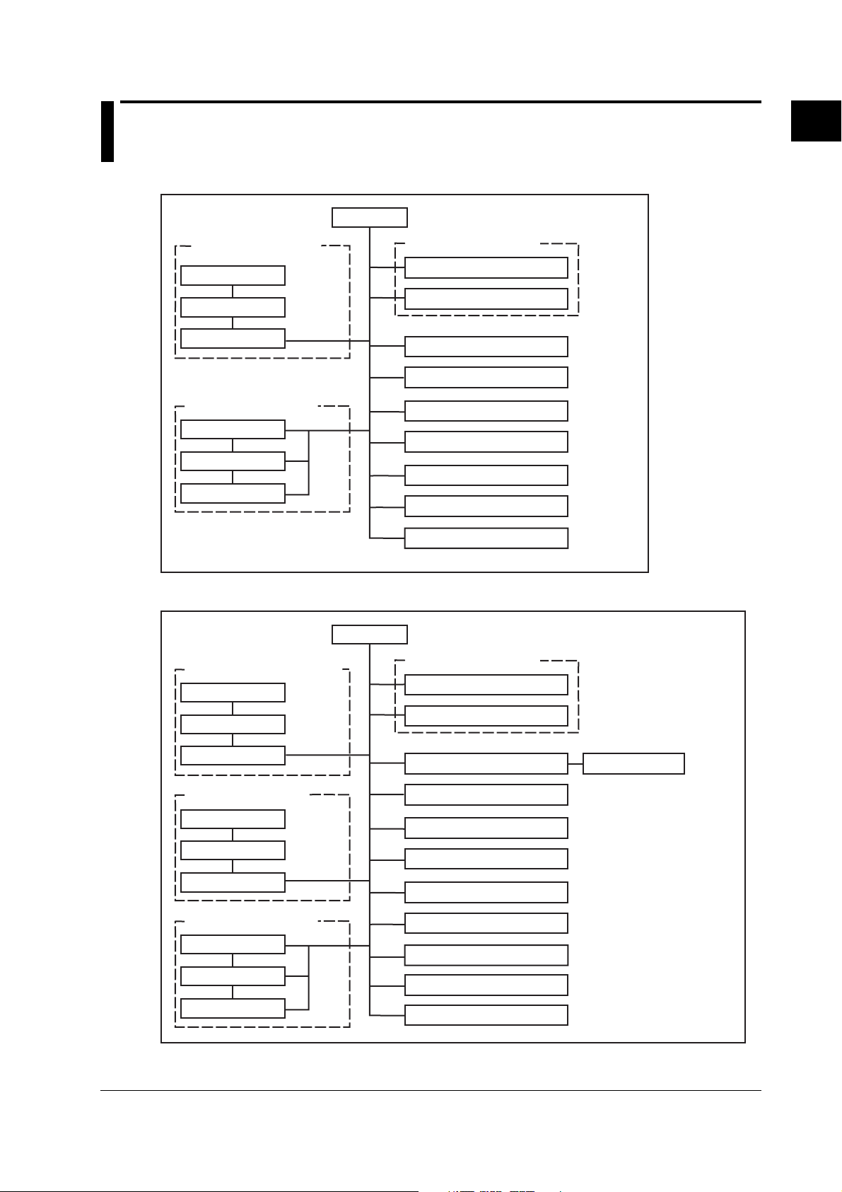
1.1 Block Diagram of the CX1000/CX2000
Block Diagram of the CX1000
CPU
Control/Measurement
Input section
Input terminal
Scanner assembly
A/D assembly
Control Output section
Control Output
Contact Input
Contact Output
Data storage functions
External storage
Internal memory
Display unit
Calculation function
Measurement Alarm function
Control Alarm function
Communication function
Remote function
(optional)
1
Principles of Operation
Block Diagram of the CX2000
Measurement Input section
Input terminal
Scanner assembly
A/D assembly
Control Input section
Input terminal
Scanner assembly
A/D assembly
Control Output section
Control Output
Contact Input
Contact Output
CPU
Measurement Alarm Relay
Data storage functions
External storage
Internal memory
Display unit
Calculation function
Measurement Alarm function
Control Alarm function
Communication function
Remote function
Measurement Alarm Relay
Transmitter power supply
Control - purpose DIO
(optional)
VGA out function (optional)
(optional)
(optional)
(optional)
(optional)
IM 04L31A01-01E
Refer for details see schematic diagram page 6-1 and 6-2.
1-1

1.2 Input Section
A/D Assembly
The A/D assembly has items such as a programmable gain amp, voltage reference,
PWM modulator, current source for RTD measurements, differential amp, voltage source
for RJC, serial parallel converter, control logic, and an occurred scanner SSR control
signal.
The A/D assembly uses a sinewave oscillating type self-resonant switching power supply
(DC/DC converter), and noise filtering is achieved by signal integration.
The A/D assembly detects the frequency of the power while it is ON and the integrated
time becomes 20 ms or 16.67 ms. Therefore it carries a very high rate of noise rejection
for the power frequency (in auto mode).
In case the power frequency of the instrument and of the measured object are different,
the appropriate integrated time is manually selectable. In case of the CX2000, the
selection of 100 ms for 50/60 Hz is also available. A 16 bit resolution is achieved
regardless of the integrated time.
Input Terminal
The internal printboard is isothermal because a print board with a metal core is being
used. Therefore, stable reference junction compensation is realized.
Scanner Assembly
An in-house SSR (solid state relay) is being used for the scanner. The SSR, having a
semiconductor switch, has a withstand voltage as high as 1500 V and a leakage current
of only 1 nA. For that reason, it has the following features.
• Semi-infinite life due to the absence of mechanical contacts
• Silent operation
• No occurrence of thermoelectric power.
On the other hand, compared to a mechanical relay, the SSR has, the disadvantage of a
bigger ON resistance and OFF capacity. As a result, RTD measurement and noise
resistance characteristics are affected. Regarding RTD measurements, a differential
amp was inserted into the previously mentioned analog circuit without increasing the
number of parts, so that it would receive no influence from ON resistance.
For RTD measurements in Measurement input section there is generally no insulation
between channels.
For RTD measurements in Control input section there is generally insulation between
channels.
Data Storage Functions
For storing data, the CX1000/CX2000 has 1.2 MB of internal memory and is equipped
with a Zip drive, or an ATA flash memory card drive. The measured data can also be
saved to external storage media such as floppy disks, Zip disks, and ATA flash memory
cards.
Display Unit
The CX has a 5.5-inch (CX1000) or 10.4-inch (CX2000) TFT color LCD on which it
displays the measured results (240 (vertical) × 320 (horizontal) pixels for the CX1000 or
480 (vertical) × 640 (horizontal) pixels for the CX2000).
1-2 IM 04L31A01-01E

1.2 Input Section
Calculation Function
The CX1000/CX2000 performs differential computation, linear scaling, and square roots
using a microprocessor on the CPU board.
Measurement Alarm Function
The following eight alarm types can be set.
High limit (H), low limit (L), differential high limit (h), differential low limit (l), rate-ofchange on increase (R), rate-of-change on decrease (r), alarm delay upper limit alarm
(T), or alarm delay lower limit alarm (t).
Control Alarm Function
The following nine alarm types can be set.
PV high-limit, PV low-limit, Deviation high-limit, Deviation low-limit, Deviation high & low
limit, SP high-limit, SP low-limit, Output high-limit, Output low-limit
Other Functions
• Communication Function:
Ethernet (standard)
RS-232/RS-422A interface added (optional).
• Remote Function:
The trigger, start/stop, time adjustment, and other functions can be controlled
remotely (optional).
• Measurement Alarm Relay:
Measurement alarm output and memory end/fail output (option for CX1006 and
CX2000).
• Transmitter Power Supply:
DC24 V output for transmitter (only CX2000’s optional).
• VGA Out Function (Option for CX2000 Only):
The instrument's screen can be displayed on an external monitor via VGA output.
• Control - Purpose DIO (CX2000 Only):
Contact input
Input for designated operations such as start/stop. Activate using a no-voltage
contact or open collector signal. This is a 12-point input.
Contact output
Control Alarm output consists of 12 points of transistor contact output.
1
Principles of Operation
Control Output Section
IM 04L31A01-01E
Control Output
The following types are available for universal control output.
• Current output (continuous PID control output)
Continuously output a current (analog signal) proportional to the calculated PID values.
• Time proportional PID voltage pulse output
Output an ON/OFF signal, having a pulse width proportional to the time, as a voltage
per the calculated PID values.
• On/Off control relay contact output
• Output an ON/OFF signal, having a pulse width proportional to the time, at a relay
contact point per the calculated PID values.
• Output an ON/OFF signal to a relay contact point corresponding to the sign (+/–) of
the deviation in the measured value from the specified target value.
Contact Input
Input for designated operations such as start/stop. Activate using a no-voltage contact
or open collector signal.
Contact Output
Control Alarm output consists of relay contact output and transistor contact output.
1-3

Chapter 2 Testing
2.1 Overview of Tests
The following describes general testing procedures for DAQSTATION CX1000/CX2000
series instruments. For tests on specific modules or assemblies, see sections 2.3 and
later.
Operating Conditions
Ambient Temperature: 23 ± 2°C
Relative Humidity: 55 ± 20%
Test Instruments
Testing Conditions
The tests cover all included A/D converters.
The unit's analog input is in analog multiplexer format.
For the CX1000, channel group 1–6 of the measurement input section and channel
group 7–11 of the control input section are each assigned to one A/D converter. For the
CX2000, channel groups 1–5 and 6–10 of the control input section (slot 1) and channel
groups 1–10 and 11-20 of the measurement input section (slots 2 and 3) are each
assigned to one A/D converter.
Therefore, except for when specifying inputs linked to the same A/D converter, only one arbitrary
channel within a group need be tested (for example, not channels 1—5 but only channel 1).
2
Testing
Instrument Specifications
DC voltage generator Accuracy: 0.005% of setting + 1 mV
DMM Accuracy: 0.005% of rdg + 1 mV
Resistors Accuracy: 0.01% or better
Insulation tester 500 VDC
Withstanding voltage tester AC 1 to 3 kV, 500 VDC
External monitor (for test of /D5 option) VGA monitor (H: 33.3 kHz, V: 60.168 Hz)
Oscilloscope 200 kS/s or more, isolated input
Thermostatic chamber ZC-114 (Coper Electronics Co., Ltd.) or equivalent
SM 04L31A01-01E
2-1

2.1 Overview of Tests
Tests
Insulation Resistance Test
Withstand Voltage Test
Measurement Accuracy Test
Error between Channels Test
Excessive Input Test
Burnout Test
Reference Junction Compensation Accuracy Test
Display Function Test
VGA Output Function Test (For /D5 Option Only)
Serial Communications Function Test (Only When The -1 Or -2 Suffix Code Is
Specified For The Communications Port).
Battery Backup Function Test
Continuous Operation Test
Current Output Accuracy Test
Voltage Pulse Output Test
Control Output Relay Test
DIO Test
KEY Function Test
Media Function Test
Alarm Relay Output Function Test (Only If The /A6, /A6R, /A4F, Or /A4FR Option Is Installed)
Remote Function Test (Only If The /A6R Or /A4FR Option Is Installed)
Communications Function Test (Ethernet)
Test of 24 VDC Transmitter Power Output (Only If The /TPS4 Is Installed)
Consult your nearest Yokogawa representative regarding the following tests.
Power Supply Frequency Detection Function Test
Memory Test
2-2 SM 04L31A01-01E

2.2 Test Procedures
Insulation Resistance Test
Perform this test using a DC 500 V insulation resistance meter and confirm that the
results meet the criteria below.
Terminals Reference Values Notes
Power terminal to earth terminal 100 MΩ or higher Short all channels prior to test
Measurement input terminal to
earth terminal
Control input terminal to earth
terminal
RS-422-A/485 SG terminal to 100 MΩ or higher Test only if the basic
RS-422-A/485 FG terminal specification code for the
Ethernet input/output terminal 100 MΩ or higher Short all terminals prior to test
to earth terminal
Withstand Voltage Test
Perform the test using a withstanding voltage tester and confirm that the results meet the
criteria below, and that the instrument does not malfunction.
Terminal Reference Values
AC power terminal to earth terminal* Leakage current of 10 mA or less at 1.5 kV AC for 1 minute
DC power terminal to earth terminal (/P1)* Leakage current of 10 mA or less at 0.5 kV AC for 1 minute
Measurement input terminal to earth terminal
Control input terminal to earth terminal
Between measuring input terminals
Between control input terminals
Current and voltage pulse to earth terminal
Control relay terminal to earth terminal Leakage current of 2 mA or less at 1.5 kV AC for 1 minute
(2, 4, and 6 loop models)
DO relay terminal to earth terminal Leakage current of 2 mA or less at 1.5 kV AC for 1 minute
(2, 4, and 6 loop models)
DO(Tr) terminal to earth terminal Leakage current of 2 mA or less at 0.5 kV AC for 1 minute
(2, 4, and 6 loop models or /CST1)**
D1 terminal to earth terminal Leakage current of 2 mA or less at 0.5 kV AC for 1 minute
(2, 4, and 6 loop models or /CST1)
Alarm relay terminal to earth terminal Leakage current of 2 mA or less at 1.5 kV AC for 1 minute
(/A6, /A6R, /A4F, /A4FR)
Remote terminal to earth terminal (/A6R, /A4FR)
24 V transmitter power supply output to earth terminal Leakage current of 10 mA or less at 0.5 kV AC for 1 minute
||||
(/TPS4)
* Short L and N (or +/– with the /P1 option)
† Short all channels
‡ Short the + and – input terminals (except for the RTD b terminal)
Short the even and odd channels (for example, short channels 1-3-5 and 2-4-6 on the CX1000 or channels 1-3-
5-7-9 and channels 2-4-6-8-10 for the CX2000), and test the withstanding voltage between them.
§ Short mA, PULS, and C.
|| Short NO, NC, and C on CTRL OUT.
# Short 1NO, 1C, and 2NO on DO.
** Short DO3—DO6 and C.
†† Short all DI terminals.
‡‡ Short all alarm relay terminals.
§§ Short all remote terminals.
|||| Short all transmitter power supply output terminals (+/–).
2
Testing
communications port is -2.
†
†
‡
‡
§
||
#
††
‡‡
Leakage current of 2 mA or less at 1.5 kV AC for 1 minute
Leakage current of 2 mA or less at 1.5 kV AC for 1 minute
Leakage current of 1 mA or less at 1 kV AC for 1 minute
Leakage current of 1 mA or less at 1 kV AC for 1 minute
Leakage current of 2 mA or less at 1 kV AC for 1 minute
§§
Leakage current of 2 mA or less at 0.5 kV AC for 1 minute
SM 04L31A01-01E
2-3

2.2 Test Procedures
Measurement Accuracy Test (Measurement Input and Control Input)
Check that the specifications below are met given the following operating conditions: 23
± 2°C, 55 ± 10% RH, and a warm up time of 30 minutes.
Range Input Value Criterion Specifications
20 mV +20.00 mV ±3 digits ±(0.1% of rdg + 2 digits)
60 mV +60.00 mV ±6 digits ±(0.1% of rdg + 2 digits)
200 mV +200.0 mV ±3 digits ±(0.1% of rdg + 2 digits)
2 V +2.000 V ±3 digits ±(0.1% of rdg + 2 digits)
6 V +6.000 V ±6 digits ±(0.1% of rdg + 2 digits)
20 V +20.00 V ±3 digits ±(0.1% of rdg + 2 digits)
50 V +30.00 V ±5 digits ±(0.1% of rdg + 3 digits)
Pt100 18.52Ω/–200°C ±0.4°C ±(0.15% of rdg + 0.3°C)
0.00 mV ±2 digits
–20.00 mV ±3 digits
0.00 mV ±2 digits
–60.00 mV ±6 digits
0.0 mV ±1 digits
–200.0 mV ±3 digits
0.000 V ±1 digits
–2.000 V ±3 digits
0.000 V ±1 digits
–6.000 V ±6 digits
0.00 V ±1 digits
–20.00 V ±3 digits
0.00 V ±2 digits
–30.00 V ±5 digits
100.00Ω/0°C ±0.2°C
313.71Ω/600°C ±0.9°C
Error between Channels Test
Connect the (+), (–), and (b) terminals on all measurement and control input channels
using thick leads, then check whether the following criteria are met.
Range Input Value Criterion
20 mV Short (+) (–) 0.00 mV ±2 digits
Pt100 103.9 Ω Measured value: 10°C ± 0.2°C,difference between channels:
0.2°C or less
Note
• If the measurement error does not meet the criterion (10°C ± 0.2°C), and unless you
determine the cause to be the effect of the resistance in the test facility's RTD wiring, use
the following measurement criteria.
Measured value: 10°C ± 0.5°C
Difference between channels: 0.2°C or less
• See your nearest Yokogawa representative for the error between channels in the control
input section.
Excessive Input Test
1. Connect the plus (+) and minus (–) sides of all measurement and control input
channels.
2. Set all channels to the 20 mV range.
3. Apply 10 V between the plus and minus sides for 1 minute, and confirm that
there is no malfunction.
4. Set all channels to the Pt100 range.
5. Apply ±10 V between (A) and (B) for 1 minute, and confirm that there is no
malfunction.
2-4 SM 04L31A01-01E
Burnout Test
1. Connect a 2 kΩ resistor between the plus (+) and minus (–) sides of an arbitrary
channel.
2. Connect 56 kΩ resistor and a 0.1 µF capacitor in parallel between the plus (+)
and minus (–) sides of an arbitrary channel other than the one in step 1.
3. Set the range for the 2 connected channels to TC - TYPE K, and the Burnout to
ON.
4. Check that the channel to which 2 kΩ was connected displays a temperature
close to the room temperature.
5. Check that the channel to which the 56 kΩ resistor and the 0.1 µF capacitor
were connected in parallel displays Burnout (overrange).
6. Set Burnout to OFF.
7. Check that both channels in steps 1 and 2 do not display Overrange.
Reference Junction Compensation Accuracy Test
Perform 0°C measurement for TYPE - T on all control and measurement channels, and
confirm that the result is below the following reference value.
Reference value: 0 ± 0.5°C
CAUTION
• Use a calibrated non-insulated thermocouple without a terminal tip, having a Φ0.5 mm or
narrower strand. Also, be sure to take the level of calibration error into consideration
during testing.
• Continuously monitor the thermostatic chamber, and check that the temperature remains
at 0°C ± 0.01°C.
• When using a 0°C thermostatic chamber (for example the ZC-114 by Coper Electronics
Co. Ltd.) raise the tip of the thermocouple up 10 mm from the bottom.
• Conduct all tests in a stable environment.
• Install a windbreak if necessary.
• Allow a 15 minute warm up after wiring the thermocouple.
• Always use the terminal covers.
2.2 Test Procedures
2
Testing
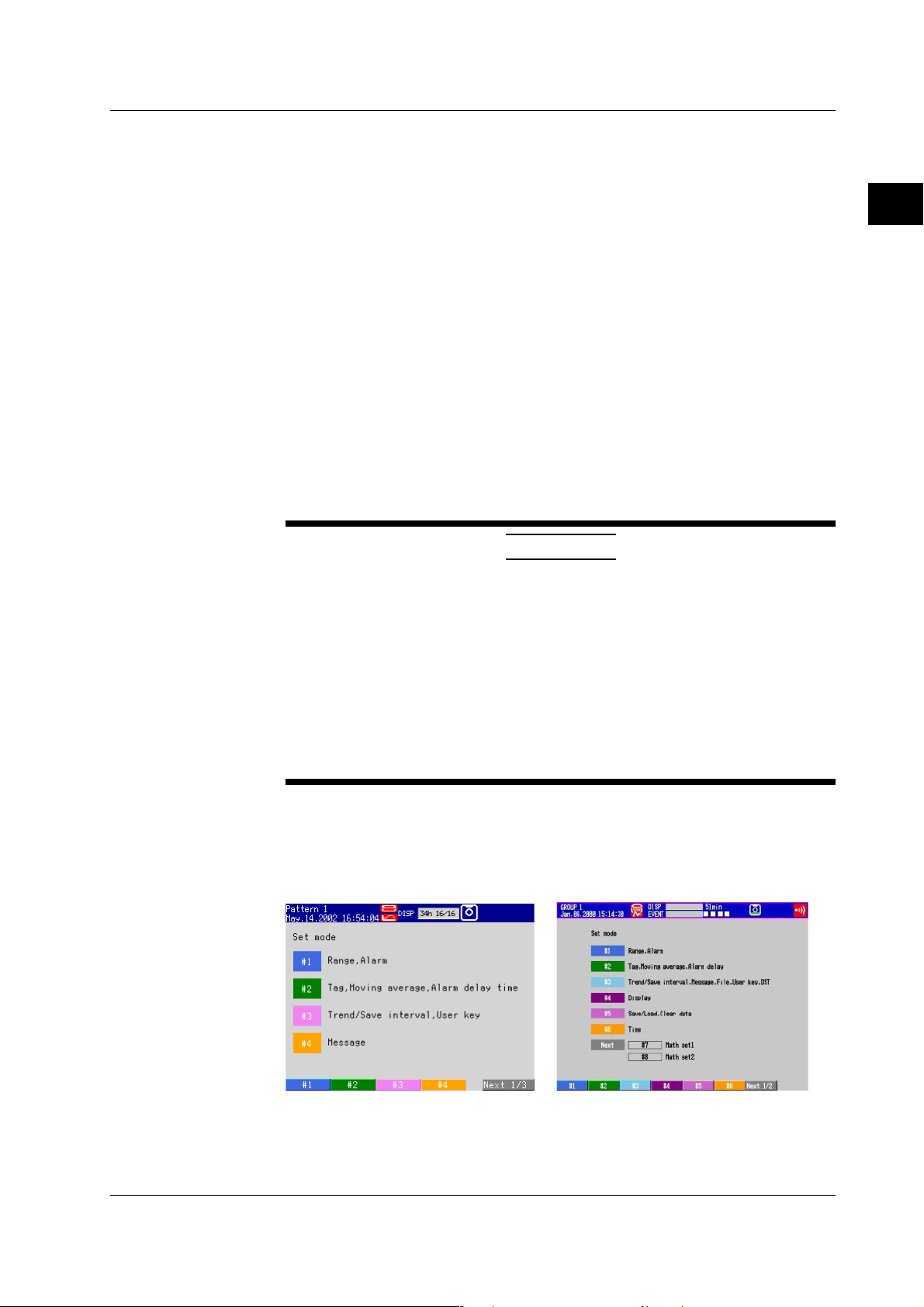
Display Function
SM 04L31A01-01E
Check the adjustment of the display color and backlight intensity using the following
procedure.
1. Press the MENU key twice to enter Set mode. The Set mode screen is
displayed.
2. Press the Display soft key.
3. Select Color.
4. The default color and color name is displayed for each channel; compare the
colors and their names to make sure there are no discrepancies.
2-5

2.2 Test Procedures
5. Press ESC to return to the previous screen.
6. Press the View, Direction, LCD soft key.
7. Move the cursor to Brightness.
8. For the CX1000, select 1 through 8 and confirm that each brightness level is
brighter than the one before it. For the CX2000, select 1 through 4 and confirm
that each brightness level is brighter than the one before it.
9. During other phases of testing as well, always be checking for any abnormalities
in the display that may appear.
10. Set Brightness to 3.
VGA Output Function Test (for the /D5 Option Only)
Connect a VGA monitor to the VGA output terminal on the back of the CX2000, then look
at the screen to check the VGA output. Perform steps 1—10 above for the display
function and check the results.
Serial Communications Function Test (Only If the -1 or -2 Suffix Code is Specified for
the Communications Port)
During this test, actual communications are performed to check whether the RS-232,
RS-422A/485, or other functions are operating properly. However, if you used serial
communications successfully to carry out other tests, you don't need to perform this test.
Perform the tests using the procedure below.
1. Connect a cable between the PC and the CX1000/CX2000.
If communications cannot be carried out via RS-422A/485, use an RS-232 adapter.
2. Send an arbitrary command from the PC using application software for CX1000/
CX2000 series instruments or other software, and confirm that the expected result
occurs.
Battery Backup Function Test
1. While the CX1000/CX2000 is ON, set the date and time (see section 3.3,
“Setting the Date and Time” in manual IM 04L31A01-01E or IM 04L31A01-03E).
2. Turn the power OFF.
3. Wait at least one minute, then turn the power back ON.
4. Confirm that the date and time set in step 1 are correct.
Continuous Operation Test
1. Enter the following settings.
• Enter AUTO SAVE to the media (see section 9.1 of the manual, IM 04L31A01-
01).
• Set all channels to a range of 20 V (see section 4.6 of the manual, IM 04L31A01-
01).
• Set input to open.
• Set display type to waveform display (see section 1.16 of the manual, IM 04L31A01-
01).
2. Press the START key.
3. Run the instrument continuously for 24 hours or more.
4. Press the STOP key.
5. Check the following:
• That a data file was created in the MEDIA INFO screen (see section 4.6 of
the manual, IM 04L31A01-01E).
• That there is no abnormal variation in the straight line waveform.
• That there is no other strange sound or odor coming from the instrument.
2-6 SM 04L31A01-01E
Current Output Accuracy
1. Change the mode to setup and choose Control, Control action, and then Input
2. Set the type of control output to Current-output and analog output to 4-20 mA
3. Press the DISP/ENTER key and choose Control and then Control groups to
4. Choose a loop number to measure with a blue arrow using the arrow keys.
5. Press the MODE softkey, and change the operation mode to manual by
6. Press the RUN/STP softkey, and start control operation by choosing RUN with
7. Press the OUT softkey. Set the output ratio to 0.0% and 100.0% with the up and
2.2 Test Procedures
setting. Set the control mode to Single. Press the ESC key to return to the
preceding menu, and choose Output processing.
for all the loops, save the settings, and change the mode to normal (the cycle
time can be set freely).
display the control display.
choosing MAN with the up and down arrow keys and pressing DISP/ENTER key
to confirm it.
the up and down arrow keys and pressing DISP/ENTER key to confirm it.
down arrow keys and measure each output current with an ammeter or the like.
Verify that the measured currents are within the ranges as shown in the table
below.
Output Ratio Reference Value Allowable Range
0.0% 4 mA 3.984 to 4.016 mA
100.0% 20 mA 19.984 to 20.016 mA
(Load condition: 250 Ω ±1%)
2
Testing
Voltage Pulse Output
Control Relay Output
1. Choose Output processing by following the procedures in step 1 of “Current
Output Accuracy.”
2. Set the type of control output to Voltage-pulse and the cycle time to 1 second
for all the loops, save the settings, and change the mode to normal (the type of
analog output can be set freely).
3. Change the operation mode to manual and start control operation by following
the procedures of steps 5 and 6 of “Current Output Accuracy.”
4. Press the OUT softkey. Set the output ratio to 20.0% with the up and down
arrow keys and observe the output voltage waveform on an oscilloscope or the
like. Verify that a rectangular waveform is displayed at a 1-second interval (0.2second high and 0.8-second low) and 12 V ± 5%.
1. Choose Output processing by following the procedures in step 1 of “Current
Output Accuracy.”
2. Set the type of control output to On/Off-control for all the loops, save the
settings, and change the mode to normal (the cycle time and type of analog
output can be set freely).
3. Change the operation mode to manual and start control operation by following
the procedures of steps 5 and 6 of “Current Output Accuracy.”
4. Press the OUT softkey. Set the output ratio to 0.0% and 100.0% with the up and
down arrow keys and verify that the relay outputs are as follows:
SM 04L31A01-01E
Output Ratio NO-C NC-C
0.0% Break Make
100.0% Make Break
2-7
2.2 Test Procedures
Test of Digital Input/Output (not applicable for models CXx0xx)
Digital Input
1. Press the DISP/ENTER key and choose CONTROL and then DI/DO STATUS.
2. The digital input terminals are divided into blocks. Short-circuit between the
common terminal and the terminals, and check the DI status display. The
indicator is green for an open circuit and red for a short circuit.
Digital Output
1. Short-circuit input terminals of all channels and adjust the range and alarm
setting as follows:
Mode
Range
Alarm
(Level 1)
Range
Span
On
Type
Value
2. Prepare the same input terminals step 1, and adjust the alarm relay output as
follows:
Alarm
(Level 1)
Voltage
2 V
–2.000 to 2.000
H
–1.000
Relay Output
No.
On
DOxxx and ROxxx
where xxx: digital
output number to test
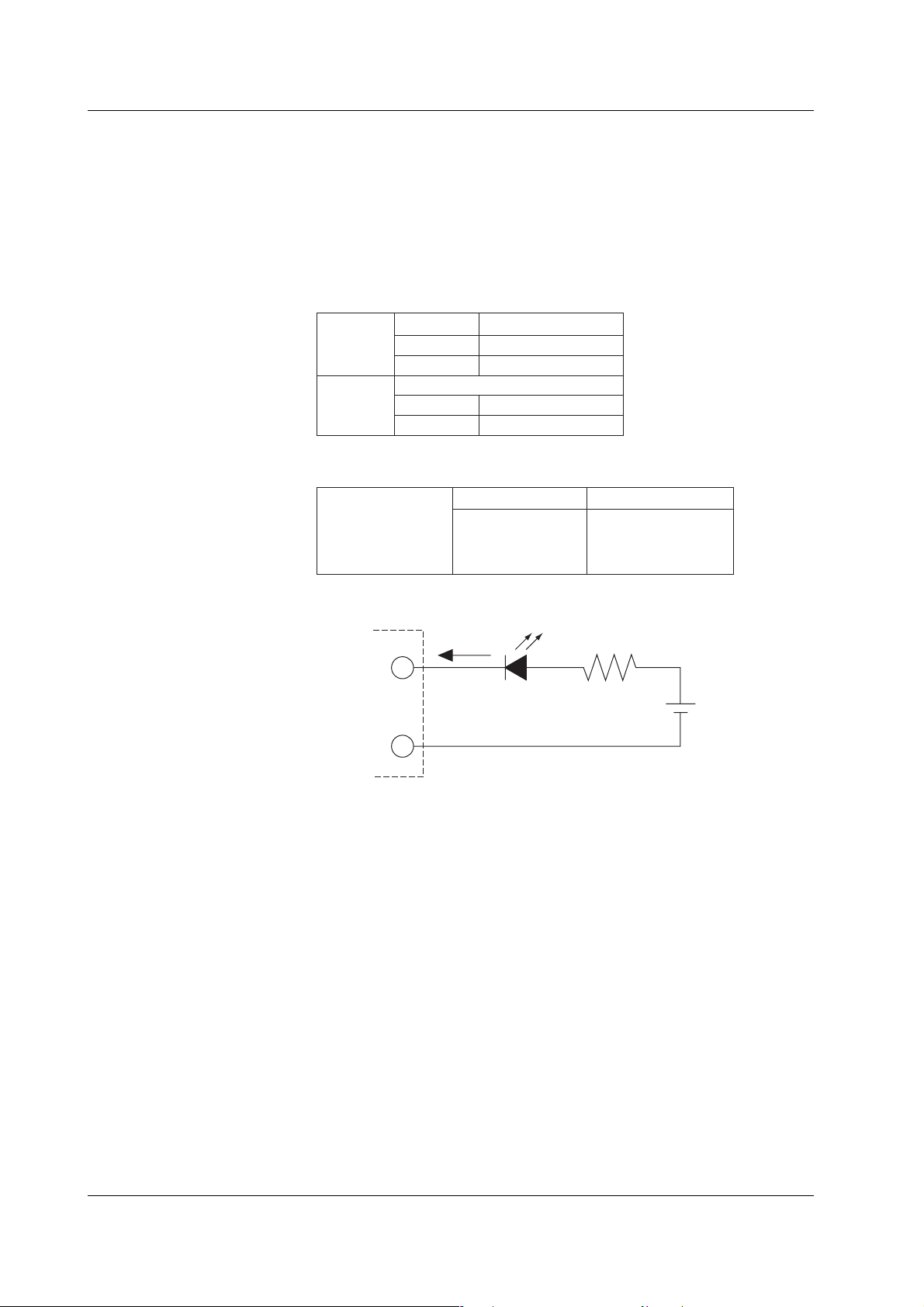
3. Verify that a digital output turns on using an appropriate tester with the following
circuit:
DO terminal
Common
Test of Power Supply Voltage Switching
Change the power supply voltage to 240 V AC and verify that the UUT display does not
malfunction.
Note that this test does not apply to the 24 V AC/DC-driven model (option code: /P1).
Test of Ethernet Interface
Use a computer in which the standard software “DAQSTANDARD for CX” is installed
and that has an Ethernet communication function, for the following test.
Run the launcher program. Select Ethernet in the network settings and make the
communication settings. Then, verify that the settings of the UUT, such as the ranges,
can be set up correctly as well as those settings can be read from the computer using
the settings software.
I ≤ 50 mA
R
LED
V ≤ 24 V DC
Test of Storage Drive
1. Insert a formatted disk into the drive of the UUT.
2. In the set mode*1, choose Save/Load, Clear data, and then Save settings. Save
the current panel conditions under a desired filename.
3. In the set mode, choose Save/Load, Clear data, and then File list. Verify that the
file saved in step 2 exists in the list.
2-8 SM 04L31A01-01E
2.2 Test Procedures
Test of Storage Drive
1. Insert a formatted disk into the drive of the UUT.
2. In the set mode*1, choose Save/Load, Clear data, and then Save settings. Save
the current panel conditions under a desired filename.
3. In the set mode, choose Save/Load, Clear data, and then File list. Verify that the
file saved in step 2 exists in the list.
Test of Alarm Relay Contact Outputs (applicable to option codes /A6, /A6R, /A4F and /
A4FR)
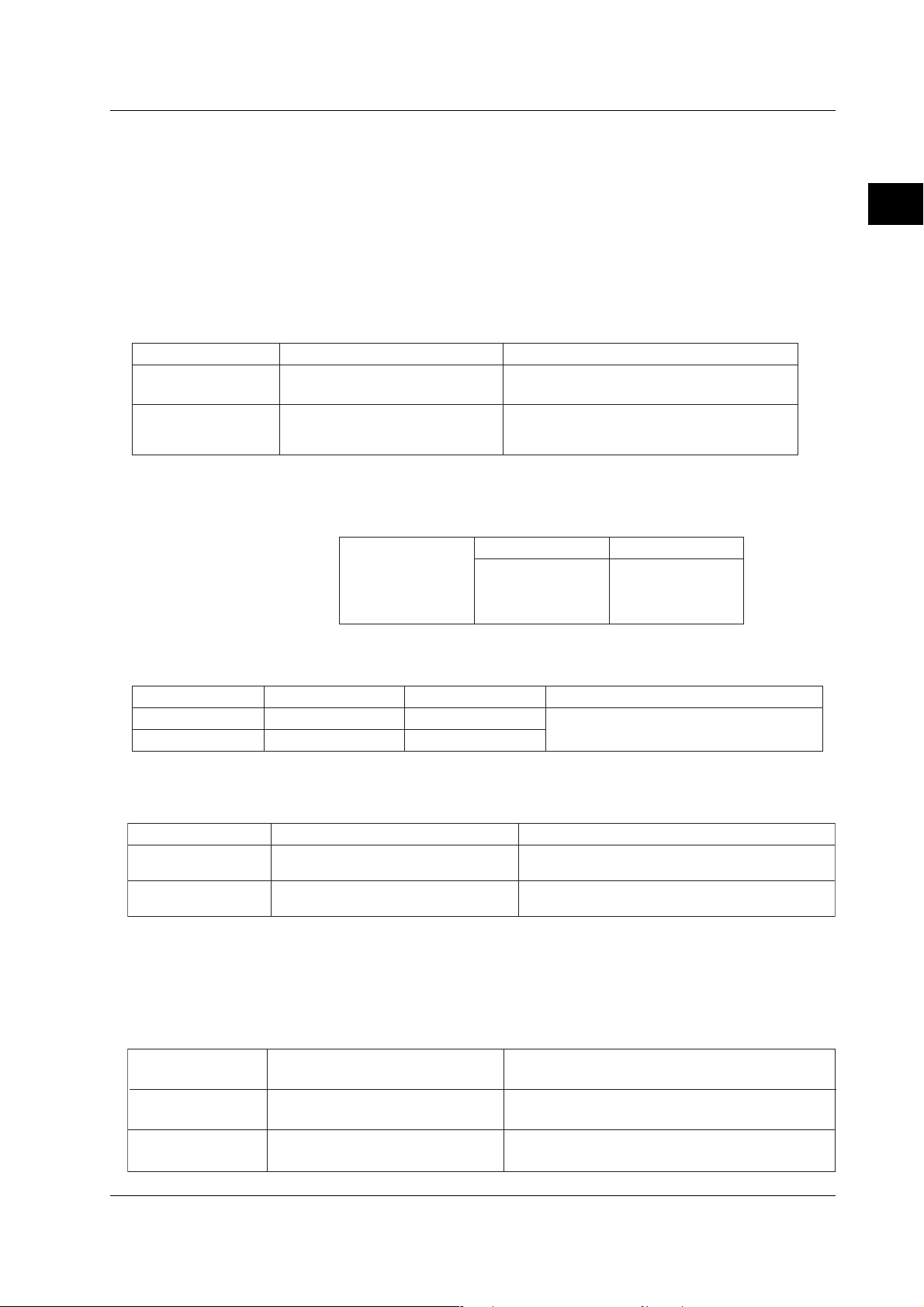
Insulation Resistance and Withstanding Voltage Tests
Item Measured Point Specification
Insulation resistance No less than 20 MΩ at 500 V DC
Withstanding voltage As above
Between relay output terminals and
grounding terminal
Free from damage after applying 1500 V AC,
50/60 Hz for 1 minute (with breaking leakage
current set to 2 mA)
Alarm Actions
1. Prepare the same input terminals and settings as step 1 in “Digital Output”
(page 2-8), and also adjust the alarm relay output as follows:
2
Testing
On/off
Ixx
where xx: alarm
output number to test
Alarm
(Level 1)
Relay Output
No.
2. Verify that an alarm contact works as follows upon turning on/off the
corresponding relay output.
Terminals Normal Remarks
NO–C Break Where the output relay action is set to
During Alarm
Make
Break
normally de-energized (factory set)NC–C Make
Test of Remote Control (applicable to option codes /A6R and /A4FR)
Insulation Resistance and Withstanding Voltage Tests
Item Measured Point Specification
Insulation resistance Between remote control terminals and
grounding terminal
Withstanding voltage As above
Remote Control Actions
Assign individual functions to 8 remote control inputs, then short-circuit each of those
inputs in turn and verify that the CX1000/CX2000 is controlled as specified.
No less than 20 MΩ at 500 V DC
Free from damage after applying 500 V DC for 2
minute (with breaking leakage current set to 2 mA)
Test of 24 VDC Transmitter Power Output (applicable to option code /TPS4)
Test of Insuration Resistance and Withstanding Voltage
Insulation resistance Between 24 VDC output terminals and
grounding terminal
As above
Withstanding voltage
SM 04L31A01-01E
Between 24VDC output terminals
No less than 20 MΩ at 500 VDC
Free from damage after applying 500 VAC, 50/60 Hz for
1 minute (with breaking leakage current set to 10 mA)
Free from damage after applying 500 VAC, 50/60 Hz for
1 minute (with breaking leakage current set to 10 mA)
2-9
2.3 CTRL Module Assembly Tests
This section describes the test procedure for CTRL MODULE ASSY (B8700CL,
B8700CM, B8700CN, and B8700FT) which is used on the CX2000. This test is not
necessary if you will perform the general tests in section 2.2. Perform this test on the
module by itself.
Test Instruments
Instrument Specifications
DC current meter Accuracy: 0.01% of rdg
Withstanding voltage tester AC 1 to 3 kV, 500 VDC
Oscilloscope 200 kS/s or more, isolated input
Resistor 250 Ω ±1%
Jig A measurement instrument having the same functions and
Tests
• Withstand Voltage Test
Consult your nearest Yokogawa representative regarding the following tests.
• Output Accuracy Test
• Voltage Pulse Output Test
• Control Relay Output Test
• DI Test
• DO Test
characteristics as the CX2000 or CX1000.
Testing Environment
Ambient temperature of 23±5°C, relative humidity of 55 ±20%
CAUTION
• Before starting the test, allow the instrument to warm up for 30 minutes or more.
• Make sure the module is installed in the CX1000/CX2000.
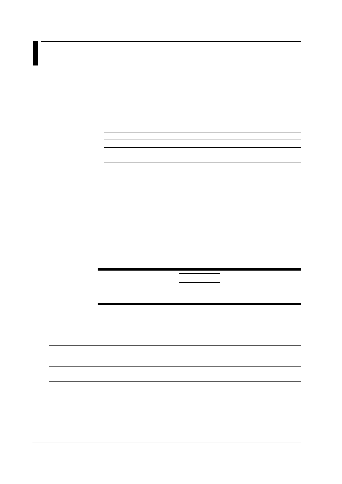
Test Procedure
Perform a withstand voltage test on the module installed in the CX1000/CX2000 at the
points listed below.
Test Points Reference Values
Current and voltage pulse output to earth terminal on Leakage current of 2 mA or less at 1 kV AC for 1 minute
the CX1000/CX2000*
Control relay terminal to CX1000/CX2000 earth terminal
DO relay terminal to CX1000/CX2000 earth terminal
DO (Tr) relay terminal to CX1000/CX2000 earth terminal
DI terminal to CX1000/CX2000 earth terminal
* Short mA, PULS, and C.
† Short NO, NC, and C.
‡ Short NO and C.
§ Short DO3—6 and C.
|| Short all DIs.
||
†
Leakage current of 2 mA or less at 1.5 kV AC for 1 minute
‡
Leakage current of 2 mA or less at 1.5 kV AC for 1 minute
§
Leakage current of 2 mA or less at 0.5 kV AC for 1 minute
Leakage current of 2 mA or less at 0.5 kV AC for 1 minute
2-10 SM 04L31A01-01E
 Loading...