

Page 1
* 4L31A173E03*
Connection Types and Procedures
CX1000 Installation and
Connection Guide
IM 04L31A01-73E 3rd Edition
3rd Edition: May 2007(YK)
All Right Reserved, Copyright © 2001
Yokogawa Electric Corporation
Thank you for purchasing the CX1000.
This manual contains simple explanations about how to install and connect
the CX1000. For more information about the procedures described herein,
safety precautions, and the CX1000 functions and operation, please refer to
the PDF manual found on the provided CD-ROM.
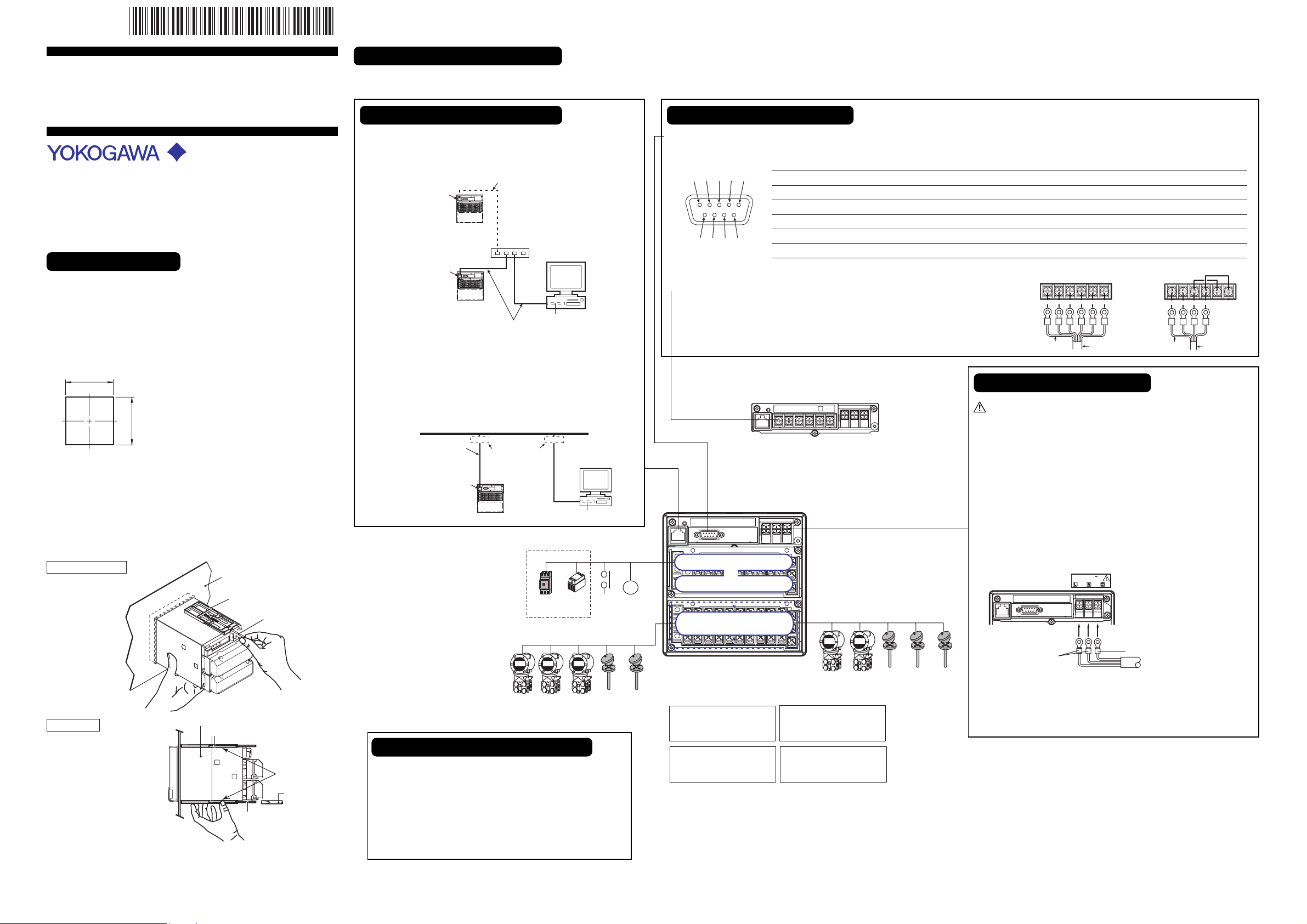
Installation Procedure
1. Cut the instrument panel according to the diagram below.
For the panel cut dimensions when installing multiple units closely
together, see the
the provided CD-ROM.
Panel Cut Diagram
When installing
a single unit
+2
137
0
2. Insert the CX1000 into the front of the panel.
3. Using the mounting brackets that came with the package, attach the
CX1000 to the panel as shown in the following figure.
First, attach the two mounting brackets and temporarily fasten the
attachment screws. Next, fix the CX1000 in place by tightening the
attachment screws with the appropriate torque (0.7 to 0.9 N-m.). As you
fasten the screws, press the mounting bracket against the case so that
they are in contact with each other.
Screw temporarily
CX1000 User’s Manual IM 04L31A01-03E
Unit: mm
+2
0
137
Yokogawa Electric Corporation
found on
Panel
Mounting bracket
Attachment screw
There are various terminals and connectors on the rear panel of the CX1000. Connecting them to peripheral devices allows you to perform control and measurement operations. Below are the names of each connector and terminal, as
well as connection procedures.
Connecting the Ethernet Interface
• When only Connecting to a Hub
Connect the CX1000 and the PC through a HUB as shown in the
Connecting the Serial Interface
• RS-232 (When Connecting to a Computer or Other Such Devices)
Verify that the CX1000 has an RS-232 connector, and then connect a serial cable to it. Connect the other end of the serial cable to the other device.
following figure.
2
1
3
Ethernet
interface connector
CX
Ethernet
interface connector
CX
10BASE-T straight cable
(Use a hub to connect
multiple units.)
Hub
10BASE-T
straight cable
Ethernet NIC
PC
• When Connecting to a Preexisting Network
• RS-422/485 (When Connecting to a PLC, Temperature Controller or
Other Such Devices)
Verify that the CX1000 has an RS-422/485 connector, and then connect the crimp
connectors (for 4-mm screws) to the terminal strip as illustrated on the right. Do not
expose more than 5 cm of the cable surface from the shield.
4 5
Pin No. Signal Name Signal Meaning
2 RD (Received Data) Received data from the connected device. Input signal.
3 SD (Send Data) Send data to the connected device. Output signal.
5 SG (Signal Ground) Signal ground.
6
8
7
9
7 RS (Request to Send)
Handshaking signal used when receiving data from the connected device. Output signal.
8 CS (Clear to Send) Handshaking signal used when sending data to the connected device. Input signal.
* Pins 1, 4, 6, and 9 are not used.
Four-wire
FG SG SDB SDA RDB RDA
Shield potential
Shield
Two-wire
FG SG SDB SDA RDB RDA
Shield potential
Shield
The following figure illustrates an example in which the CX1000 and
a PC are connected to the network. When connecting the CX1000 or
the PC to a preexisting network items such as the transfer rate and
connector type must match. For details, consult your system or
network administrator.
Network
With an RS-422/485
Connecting the Power Supply
When using electrical wiring, be certain to follow the safety
recommendations prescribed in the CX1000 User's Manual.
Use a power supply that meets the following conditions:
10BASE-T straight cable
Ethernet
interface connector
CX
10BASE-T adapters
(hubs, routers, etc.)
PC
Ethernet NIC
With an RS-232
CX1000 Rear Panel
Rated supply voltage: 100 to 240 VAC
Supply voltage range used: 90 to 132, 180 to 264 VAC
Rated supply voltage frequency: 50/60 Hz
Permitted supply voltage frequency range:
50/60 Hz ± 2%
Maximum power consumption: 39 VA (100 V), 51 VA (240 V)
1. Turn OFF the CX1000 and open the cover (transparent) for the
Controls and Switch
SSR
Magnet
switch
5 universal measurement inputs
Contact
input
6 inputs
R1
Contact
output
6 outputs
Control output terminal block
or
Option terminal block
Control/measurement input
terminal block
6 universal measurement inputs
power supply wires.
2. Connect the power cord and the protective ground cord to the power
supply terminals.
Power cord
100-240V AC
50/60Hz 51VA MAX
Protective grounding cord
Case
Front
Panel
Mounting bracket
In contact
with each other
Fix in place
Tor que driver
(The figure shows the case
when the mounting brackets
are used on the top and bottom
Attachment screw
(flat blade)
of the case.)
For details about the CX1000 external dimensions, installation environment,
and more, please refer to the
CX1000 User's Manual (IM 04L31A01-01E)
3. Close the cover (transparent) for the power supply wires and secure
it in place with screws.
For the power supply specifications and connection method of the 24VDC/AC
power supply option, please refer to the CX1000 User's Manual.
Connecting Input/Output Connectors
When connecting various input/output connectors for control or
measurement, proceed as described below.
Option terminal block (one of the following)
Measurement alarm output
(/A6 option)
Measurement alarm output
+ FAIL/memory end output
(/A4F option)
Measurement alarm output
+ remote input/output
(/A6R option)
Measurement alarm
output + FAIL/memory
end output + remote
input/output (/A4FR option)
Connect the crimp connectors (for 4-mm screws) to the terminal
strip.
1. Turn off the CX1000 and remove the terminal cover.
2. Wire the signal wires to the terminals.
Attach the terminal cover and secure it with screws.
.
Page 2
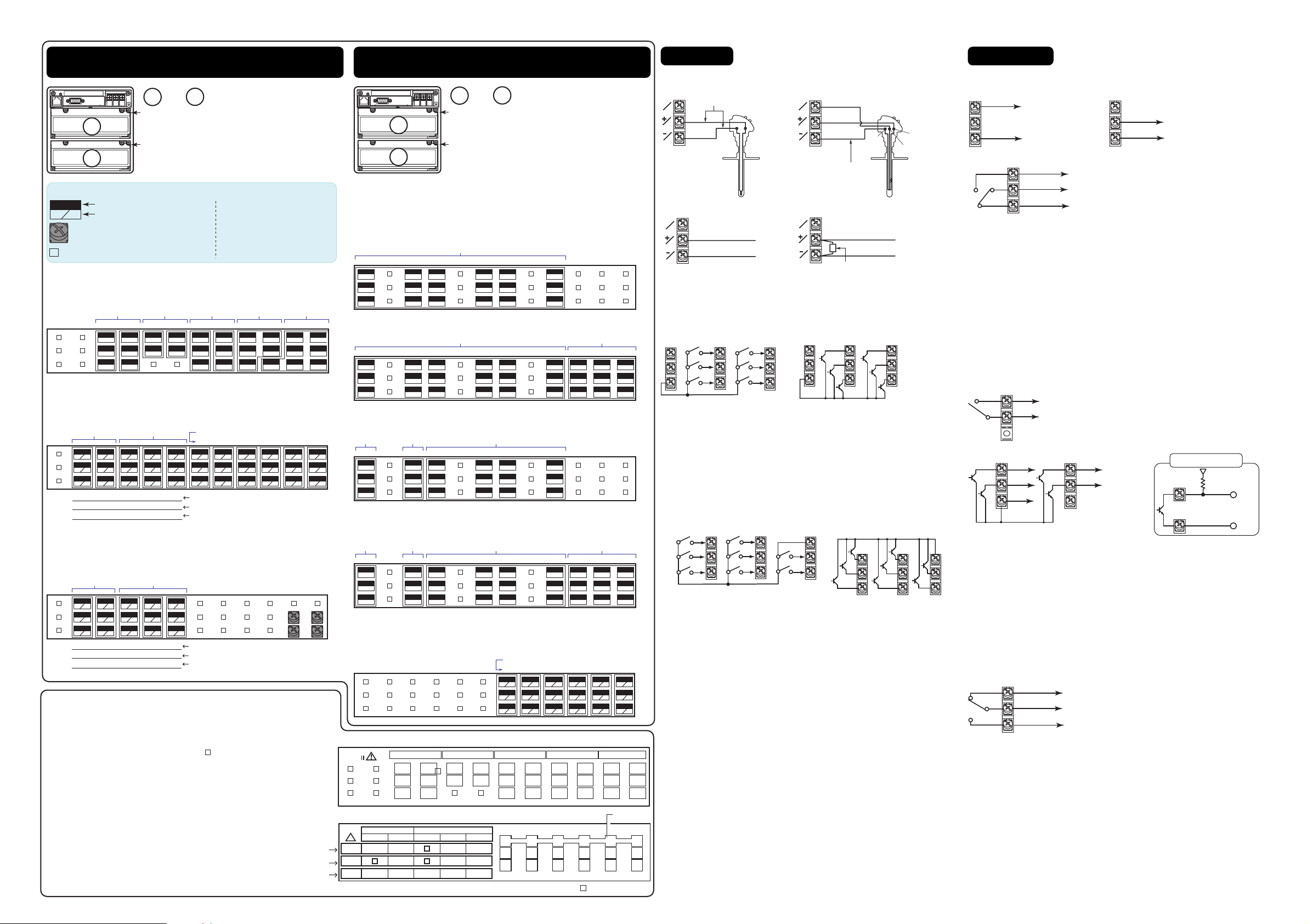
Arrangement of the Control Input/Output Terminals
on the CX1206 and CX1200
0
1
and : Terminal block number
Arrangement of the Measurement Input/Output
Terminals on the CX1006 and CX1000
Control Output Terminal Block
0
Output termials for the loops 1 and 2.
0
Analog Control Input / Measurement Input
1
Terminal Block
Input termials for the loops 1 and 2,
1
and measurement terminals.
Symbols
005
+
Te r minal number
A
Character Indicating the type
of input/output signal
For the maintenance use only.
Do not wire.
C: Common
NO: Normally Opened
NC: Normally Closed
mA: Current output
PULSE: Voltage pulse output
No screw terminal is attached.
Control Output Terminal (Terminal Block: 0)
Installed on the CX1206 and CX1200.
Control relay
contact output
LOOP1LOOP2 2
025
028
NO
NO
026
029
NC
NC
027
030
C
C
relay contact
output
022
NO
023
C
Control current/
voltage pulse output
LOOP1LOOP21
019
016
013
mA
NO
020
C
017
PULSE
018
C
mA
014
PULSE
015
Tra ns istor
output
010
5
011
6
012
C
C
007
008
009
Contact
input
004
001
4
3
4
C
005
006
1
002
5
2
003
3
6
Analog Control Input / Measurement Input Terminal (Terminal
Measurement Alarm Option Terminal (Terminal Block: 0)
The measurement alarm option terminal block is the terminal block that you
specified as an option to the CX1006 or CX1000 at the time of purchase. The
following four types are available.
/ A6
06 05 04 03 02 01
034
NC
035
C
036
NO
/ A6R
06 05 04 03 02 01
034
NC
035
C
036
NO
Block: 1)
Installed on the CX1206.
131
132
+
133
−
b
A
B
128
129
+
130
−
125
b
b
126
+
A
A
127
−
B
B
(RSP)
LOOP1LOOP2
Channel number (Measurement input terminal)
124563
122
119
116
113
110
107
104
123
+
124
−
b
b
b
b
b
120
117
+
A
A
121
−
B
B
PV(RSP)PV(RSP)
PV(RSP)PV
PV1PV2PV1PV2
114
+
+
A
A
118
115
−
−
B
B
During single loop control
During cascade control
During loop control with PV switching
111
+
112
−
b
108
+
A
A
109
−
B
B
105
+
106
−
101
b
b
102
+
A
A
103
−
B
B
[Control mode setting]
/ A4F
FAI L
output
034
NC
035
C
036
NO
/ A4FR
FAI L
output
Memory end
output
Memory end
output
Analog Control Input Terminal (Terminal Block: 1)
Installed on the CX1200.
LOOP1LOOP2
131
132
+
133
−
b
A
B
128
129
+
130
−
125
122
123
+
124
−
119
b
b
120
+
A
A
121
−
B
B
PV(RSP)PV(RSP)
During single loop control
PV(RSP)PV
During cascade control
PV1PV2PV1PV2
During loop control with PV switching
b
b
126
+
A
A
127
−
B
B
(RSP)
[Control mode setting]
Label on the Front of the Terminal Cover
The terminal numbers are written on the label on the front of the terminal cover. Terminal numbers are
unique three-digit numbers. They are used to locate terminals on the wiring diagram, etc. The highest
digit indicates the arrangement position of the terminal block; the lower two digits indicate the terminal
position within the terminal block (top right terminal is assigned "01" bottom left terminal is assigned
"36"). The terminals that cannot be used are indicated as " ".
Label on the Back of the Terminal Cover
Indicates the type of input/output signals for each terminal.
You can select the control modes from "single loop control", "cascade control", and "loop control with
PV switching" on the CX. The arrangement of the analog control input (PV) terminals are changed
depending on the control mode selected. The terminal arrangement for these three control modes are
written on the label on Analog Control Input Terminal.
[Control mode setting]
During single-loop control
During cascade control
During loop control with PV switching
PV, PV1, PV2: PV input, (RSP): RSP input(not used during program control), : unused terminal
034
NC
035
C
036
NO
Measurement Input Terminal (Terminal Block: 1)
Installed on the CX1006.
Label on the Front (For the Analog Control Output Terminal Block
CAT
028
029
030
Label on the Back (For the Analog Control Input / Measurement Input Terminal Block
CAT II
SNGL
CAS
PVSW
LOOP 2
!
( )
RSP
PV1PV2 PV2
0
1
and : Terminal block number
Measurement Alarm Option Terminal Block
Installed when you specified /A6, /A6R, /A4F, or
/A4FR at the time of purchase.
Measurement Input Terminal Block
Measurement input terminals
Alarm output
025
028
NC
NC
026
029
C
C
027
030
NO
NO
025
028
NC
NC
026
029
C
C
027
030
NO
NO
04 03 02 01
025
028
NC
NC
026
029
C
C
027
030
NO
NO
04 03 02 01
025
028
NC
NC
026
029
C
C
027
030
NO
NO
025
026
027
LOOP 1
( )
RSP
( )
RSP
( )
RSP
022
023
019
NC
020
C
021
NO
019
NC
020
C
021
NO
Alarm output
019
NC
020
C
021
NO
Alarm output
019
NC
020
C
021
NO
016
019
017
020
018
13122
PVPV
+
PVPV
-
PV1
016
NC
017
018
NO
C
010
NC
011
012
NO
C
Measurement remote inputAlarm output
010
007
008
009
004
001
3
6
7
8
005
006
C
002
4
1
003
5
2
016
NC
017
018
NO
016
NC
017
018
NO
NC
C
C
011
012
NO
010
NC
011
012
NO
C
C
Measurement remote input
010
007
008
009
107
108
+
109
−
004
001
3
6
7
8
005
006
C
002
4
1
003
5
2
124563
104
105
+
106
−
101
b
b
102
+
A
A
103
−
B
B
b
A
B
016
NC
017
018
NO
C
NC
011
012
NO
C
Channel number (Measurement input terminal)
116
113
114
+
115
−
110
b
b
111
+
A
A
112
−
B
B
117
+
118
−
b
A
B
)
007
008
009
3
+
-
)
b
A
B
DIGITAL-IN
004
001
005
002
006
003
Terminal
symbol
2
b
+
+
A
-
-
B
1
bb
A
B
DIGITAL-OUTCTRL-OUTDIGITAL-OUTCTRL-OUT
010
013
011
014
012
015
5
6
A
B
4
b
b
+
+
A
A
-
-
B
B
Input Wiring
Measurement Input Wiring
• Thermocouple input
b
A
B
Compensation lead
• DC voltage input
b
A
B
DC voltage input
+
–
Contact Input (DIGITAL IN) Wiring
• Relay contact input • Transistor input
4
5
C
6
Relay Contact Input/Transistor Input
Input signal: no-voltage contact, open collector
Input condition: ON voltage, under 0.5 V (30 mADC); OFF voltage, leakage
current under 0.25 mA
Input format: photocoupler isolation (common)
Withstand voltage: 500 VDC, 1 min (between input terminal and earth)
Measurement Alarm Option Terminal Block Contact Input
(REMOTE) Wiring
• Relay contact input
Relay Contact Input/Transistor Input
See “Relay Contact Input (DIGITAL IN) Wiring.”
6
7
8
• RTD input
b
A
B
Lead wire resistance
per wire of 10 Ω or less.
Make the resistance of
the three wires equal.
• DC current input
b
A
B
1
2
3
3
4
5
C
C
1
2
B
A
b
+
DC current input
Shunt resistor
Example: For 4 to 20 mA input,
shut resistance values should be
250 Ω ±0.1%.
4
5
6
• Transistor input
–
1
2
3
6
7
8
3
4
5
C
1
2
Output Wiring
Control Output (LOOP1 and 2) Wiring
•
•
Current output
mA
+
4 to 20 mADC or
C
0 to 20 mADC
–
• Relay contact output
NO
NC
C
250 VAC, 3 A or
30 VDC, 3 A
(resistive load)
(when set to energized)
Current Output
Output signal: 4 to 20 mADC or 0 to 20 mADC
Resistive load: 600 Ω or less
Voltage Pulse Output
Output signal: ON voltage=12 VDC
Resistive load: 600 Ω or more
Relay Contact Output
Output signal: NC, NO, COM
Contact rating: 250 VAC (50/60 Hz)/3 A or 30 VDC/3 A (resistive load)
Contact Output (DIGITAL OUT) Wiring
• Relay contact output of the control output terminal block
• Transistor output of the control output terminal block
Relay Output
Output form: relay contact
Contact rating: 250 VAC (50/60 Hz)/1 A or 30 VDC/1 A (resistive load)
Transistor Output
Output method: open collector output
Contact rating: 24 VDC/50 mA
A label indicating the terminal arrangement is affixed to the front and back
of the terminal cover of each terminal block.
NO
250 VAC, 1 A or
C
30 VDC, 1 A (resistive load)
5
6
C
Measurement Alarm Option Terminal Block Contact Output
(ALARM, FAIL, MEMORY) Wiring
NC
C
NO
Relay Output
Output form: relay contact
Contact rating: 250 VAC (50/60 Hz)/1 A or 250 VDC/0.1 A (resistive load)
250 VAC/3A,
250 VDC/0.1 A(resistive load)
Voltage pulse output
3
24 VDC/50 mA
4
PULS
C
+
Voltage pulse (12 V)
–
Connection example
for a transistor output
3 to 6
+
Pull-up resistor
C
−
 Loading...