

Page 1

User's
Manual
IM CW240E
CW240
Clamp-on Power Meter
1st Edition: June 2004 (KP)
IM CW240E
Page 2

Index
Introduction .....................................................................................1
Checking the Contents of the Package........................................ 2
Precautions for Safe Use of the Instrument ................................ 6
Utilisation en Toute Securite ......................................................... 9
Chapter 1 Product Overview ................................... 1-1
1.1 Product Overview .............................................................. 1-2
1.2 System Configuration Diagram ........................................ 1-4
Chapter 2 Part Names and How to Use Parts ......... 2-1
2.1 Front Panel and Connector Block .................................... 2-2
2.2 Operation Keys .................................................................. 2-3
2.3 Side Faces .......................................................................... 2-4
2.4 Screen Configuration ........................................................ 2-5
2.5 Overrange/Error Indication during Measurement ........... 2-6
2.6 Description of Mark Indication ....................................... 2-11
Chapter 3 Preparation for Safe Measurements ...... 3-1
3.1 Precautions for Use ........................................................... 3-2
3.2 Connecting a Power Supply ............................................. 3-4
3.3 Connecting Voltage Probes ............................................ 3-14
3.4 Connecting Clamp-on Probes ........................................ 3-15
3.5 Connection Diagrams of Voltage Probes and
Clamp-on Probes ............................................................. 3-17
3.6 Turning ON the Power Switch ......................................... 3-22
3.7 Performing Measurements with Greater Precision ...... 3-24
IM CW240E
Toc-1
Page 3

Index
Chapter 4 Wiring ........................................................ 4-1
4.1 Precautions for Wiring to the Measurement Circuit ....... 4-2
4.2 Installing the CW240 .......................................................... 4-3
4.3 Setting up Wiring ............................................................... 4-5
4.4 Setting up the Number of Loads ...................................... 4-6
4.5 Carrying out Wiring ........................................................... 4-7
4.6 Wiring the Measurement Circuit
Using External VT/CT ...................................................... 4-23
4.7 Checking Wiring ............................................................... 4-24
Chapter 5 Setting Ranges Using the Direct Keys... 5-1
5.1 Setting the Voltage Range ................................................. 5-2
5.2 Setting the Current Range ................................................ 5-4
5.3 Ranges and Number of Digits ........................................... 5-6
Chapter 6 Configuring Settings ............................... 6-1
6.1 Settings ............................................................................... 6-2
6.2 General Settings 1/2 .......................................................... 6-6
6.3 General Settings 2/2 ........................................................ 6-21
6.4 Save Data Settings 1/2 ..................................................... 6-46
6.5 Save Data Settings 2/2 ..................................................... 6-62
6.6 Communication Settings ................................................. 6-67
6.7 Voltage Quality Settings .................................................. 6-72
6.8 Hardware Settings ........................................................... 6-76
6.9 Analog I/O Settings .......................................................... 6-88
Toc-2
IM CW240E
Page 4

Index
Chapter 7 Measurements ..........................................7-1
7.1 Measurements .................................................................... 7-2
7.2 Measure Screens ............................................................... 7-3
7.3 Measuring Electric Energy .............................................. 7-13
7.4 Measuring Demand .......................................................... 7-17
7.5 Displaying Zoom (Expanded View) ................................ 7-21
7.6 Measuring Harmonics ..................................................... 7-24
7.7 Displaying Waveform ....................................................... 7-34
7.8 Measuring Voltage Quality (Voltage Dip,
Voltage Swell, or Instantaneous Interruption) ............... 7-40
7.9 Checking Settings ............................................................ 7-43
7.10 Clearing Integrated Data ................................................. 7-45
7.11 Measurement Data ........................................................... 7-46
Chapter 8 Saving Measured Data............................. 8-1
8.1 Data Save ............................................................................ 8-2
8.2 Saving Measured Data ....................................................... 8-6
8.3 Memory (Reference) ........................................................ 8-11
8.4 Backup Memory ............................................................... 8-13
8.5 Copying Screen Data (Hard copy) .................................. 8-15
Chapter 9 Processing File(s) .................................... 9-1
9.1 File Processing .................................................................. 9-2
9.2 Changing a File Name ....................................................... 9-4
9.3 Deleting a File ..................................................................... 9-6
9.4 Formatting .......................................................................... 9-9
9.5 Data Copy ......................................................................... 9-10
9.6 Setting Files (Load/Save/Delete/Name Change) ........... 9-14
9.7 Backup Memory Copy ..................................................... 9-24
9.8 Backup Memory Delete ................................................... 9-25
Chapter 10 Using the Communication Function
(RS-232) .................................................. 10-1
10.1 Description of the Communication Function ................ 10-2
10.2 Using a Personal Computer ............................................ 10-4
10.3 Using a Printer ................................................................. 10-6
IM CW240E
Toc-3
Page 5

Index
Chapter 11 PC Card ................................................... 11-1
11.1 PC Card Specifications ................................................... 11-2
11.2 Inserting and Removing the PC Card ............................ 11-3
11.3 Formatting the PC Card ................................................... 11-4
11.4 Saving in the PC Card ..................................................... 11-5
Chapter 12 Using External Control Input/Output ... 12-1
12.1 External Control Input/Output ........................................ 12-2
12.2 Connecting External Control Terminals ......................... 12-3
12.3 Using Multiple CW240 Units in Synchronization .......... 12-4
Chapter 13 Using Analog Input/Output
(Optional) ................................................ 13-1
13.1 Analog Output (DA Output) ............................................. 13-2
13.2 Analog Input ..................................................................... 13-6
13.3 Connecting Analog Input/Output Terminals .................. 13-8
Chapter 14 Power Failure Processing Function ..... 14-1
Chapter 15 Other Functions ..................................... 15-1
15.1 Holding the Display Value ............................................... 15-2
15.2 Turning the LCD Backlight ON and OFF ........................ 15-3
15.3 Locking the Keys ............................................................. 15-4
15.4 Resetting the System ...................................................... 15-5
Chapter 16 Maintenance Troubleshooting .............. 16-1
16.1 Things to Check When There is a Malfunction ............. 16-2
16.2 Error Message Content and Actions ............................. 16-4
Chapter 17 CW 240 Specifications ........................... 17-1
17.1 CW 240 Specifications ..................................................... 17-2
17.2 Specifications of Current Clamps
(Clamp-on Probe) ........................................................... 17-17
Toc-4
IM CW240E
Page 6

Index
Appendix 1 Block Diagram .................................. App.1-1
Appendix 2 File/Print Item Descriptions ............ App.2-1
Appendix 3 Polarity (Active Power, Reactive Power,
Power Factor, Phase Angle) ............ App.3-1
Appendix 4 Polarity
(Harmonic Measurement) ................App.4-1
Appendix 5 Reactive Power Method ................... App.5-1
Appendix 6 Sampling Method ............................. App.6-1
Appendix 7 Terminology ...................................... App.7-1
IM CW240E
Toc-5
Page 7

Introduction
Thank you for purchasing our CW240 Clamp-on Power Meter. This User's
Manual describes the functions of the CW240 as well as its operating methods
and handling precautions. Read this manual thoroughly before using the
CW240, to ensure correct use.
In addition to this manual, the Quick Setup Manual and Communication
Function Manual (CD-ROM) are available separately. The Quick Setup Manual
briefly describes the basic procedures for performing such tasks as setup and
measurement operations. Use the Quick Setup Manual together with this indepth User's Manual. For more information on the communication functions,
see the Communication Function Manual (CD-ROM).
After reading this manual, always keep it in an easily accessible convenient
place for later reference. This manual will come in handy when you are unsure
of how to operate the product.
Notices
The contents of this manual are subject to change without prior notice. In
addition, figures and illustrations representing display views in this manual may
differ from actual views.
Every effort has been made to ensure accuracy in the preparation of this
manual. However, should any doubts arise or errors come to your attention,
please contact one of the Yokogawa M&C sales offices listed on the back cover
of this manual, or the sales representative from whom you purchased the
product.
The contents of this manual may not be transcribed or reproduced, in part or in
their entirety, without prior permission.
Introduction
Trademark Acknowledgments
The company and product names referred to in this document are either
trademarks or registered trademarks of their respective holders.
Revision Information
First Edition: June, 2004
Disk No. CW240E
1st Edition: June, 2004 (KP)
All Rights Reserved. Copyright © 1999, Yokogawa M&C Corporation
IM CW240E
1
Page 8
Checking the Contents of the
Package
After opening the package, be sure to check the product as instructed below
before use. Should the product you have received be the wrong model, lack any
items, or show any problems in its appearance, contact the vendor from whom
you purchased the product.
Instrument Main Unit
Check the model name where MODEL is printed on the nameplate located at
the back of the CW240 to ensure that the CW240 is exactly as specified in your
purchase order.
Model and Suffix Codes
Model
CW240
AC adapter
Option codes
Suffix Code
-D
-F
-R
-S
Specifications
Power cord: UL/CSA standard
VDE standard
SAA standard
BS standard
D/A output and analog input
/DA
Clamp-on current probe for 96030, 2 pcs./set
/C1
Clamp-on current probe for 96030, 4 pcs./set
/C2
Clamp-on current probe for 96031, 2 pcs./set
/C3
Clamp-on current probe for 96031, 4 pcs./set
/C4
Clamp-on current probe for 96032, 2 pcs./set
/C5
Clamp-on current probe for 96032, 4 pcs./set
/C6
Clamp-on current probe for 96033, 2 pcs./set
/C7
Clamp-on current probe for 96033, 4 pcs./set
/C8
Clamp-on current probe for 96036, 2 pcs./set
/C9
Clamp-on current probe for 96036, 4 pcs./set
/C10
Clamp-on current probe for 96034, 2 pcs./set
/C11
Clamp-on current probe for 96034, 4 pcs./set
/C12
Clamp-on current probe for 96035, 2 pcs./set
/C13
Clamp-on current probe for 96035, 4 pcs./set
/C14
NiMH battery pack + carrying case
/PM1
No. field: denotes the product number.
Refer to this number when inquiring about the product to the vendor.
2
IM CW240E
Page 9

Checking the Contents of the Package
Accessories
Make sure that the package contains all the accessories listed below and that
they are all free from any damage.
Product Name Part No. Q'ty Remarks
1. AC adapter for
power supply
2. AA-size alkaline
batteries
3. Voltage probes 91007 4 Color: black, red, yellow, blue
4. User's Manual IM CW240 1
5. Quick Setup
Manual
6. CD-ROM 1
1. 2. 3.
4. 5. 6.
788011 1set Yokogawa's AC adapter
- 6
IM CW240P 1
IM CW240E
3
Page 10

Checking the Contents of the Package
Peripherals (Optional)
The products listed below are available as optional peripherals. For technical
and ordering inquiries concerning peripherals, contact the vendor from whom
you purchased the product. If the product you purchased includes any one of
the optional peripherals, make sure it is free from any damage.
Product Name Part No. Min. Order Q'ty Remarks
Clamp-on Probe
for 200 A 96030 1
for 500 A 96031 1
for 700 A 96032 1
for 50 A 96033 1
for 3000 A 96034 1 Large-diameter type
for 3000 A 96035 1 Flexible type
for 2 A 96036 1
Voltage probe 91007 1 set 4
Carrying case 93020 1
AC adapter 788011 1 set Yokogawa's AC adapter
NiMH battery pack 94004
AC adapter for 96035 A1020UP 1 For clamp-on Probes
Printer 97010 1
AC adapter (for printer, Europe)
94006 1
AC adapter (for printer, USA)
94007 1
Thermal paper for printer 97080 10 rolls
Memory card
(with a PC card adapter)
16 MB 97030 1
32 MB 97031 1
128 MB 97033 1
256 MB 97034 1
512 MB 97035 1
Selectable from 3000 A, 2000 A,
and 1000 A
Selectable from 3000 A and 300 A
TIP
It is advisable that the packing box be saved, as it is useful when you transport the
product.
4
IM CW240E
Page 11

Checking the Contents of the Package
Housing the CW240 Main Unit and Accessories
An optional carrying case can accommodate the CW240 main unit with its
clamp-on probes and voltage probes connected to the unit. The case can also
house such accessories as the memory card, AC adapter, and User's Manual.
As such, it comes in handy for transporting a complete kit of tools necessary for
making measurements.
● Example of Housing:
User's Manual
NiMH
battery pack
AC adapter
Clamp-on probes
CW240 main unit
Voltage probes
IM CW240E
5
Page 12

Precautions for Safe Use of the
Instrument
When operating the instrument, be sure to observe the cautionary notes given below
to ensure correct and safe use of the instrument. If you use the instrument in any way
other than as instructed in this manual, the instrument’s protective measures may be
impaired. Yokogawa M&C Corporation is by no means liable for any damage
resulting from use of the instrument in contradiction to these cautionary notes.
The following safety symbols are used on the instrument and in this manual.
Danger! Handle with Care.
This symbol indicates that the operator must refer to an explanation in the
User's Manual in order to avoid risk of injury or death of personnel or damage
to the instrument.
Hazardous Voltage
➤
The operator must never attempt to touch equipment or parts marked with this
symbol.
Direct Current
This symbol indicates DC voltage/current.
Alternating Current
This symbol indicates AC voltage/current.
ON
This symbol indicates On (power).
OFF
This symbol indicates Off (power).
Double insulation
This symbol indicates double insulation.
WARN ING
Indicates a hazard that may result in the loss of life or serious injury of the user
unless the described instruction is abided by.
CAUTION
Indicates a hazard that may result in an injury to the user and/or physical
damage to the product or other equipment unless the described instruction is
abided by.
6
IM CW240E
Page 13

Precautions for Safe Use of the Instrument
NOTE
Indicates information that is essential for handling the instrument or, should be
noted in order to familiarize yourself with the instrument’s operating procedures
and/or functions.
TIP
Indicates information that complements the present topic.
SEE ALSO
Indicates the reference location(s) for further information on the present topic.
Strictly observe the following cautionary notes in order to avoid the risk of
injury or death of personnel or damage to the instrument due to hazards
such as electrical shock.
WARNI N G
● Removal of the Case from the Instrument
•Do not remove the case from the instrument or disassemble/modify the
instrument itself.
•Some parts of the inside of the instrument contain high voltage and,
therefore, access to the internal assembly is extremely hazardous. For
inspection and/or adjustment of the internal assembly, contact the vendor
from which you purchased the instrument.
● Use of the Instrument in a Gaseous Atmosphere
Do not operate the instrument in a location where any flammable or explosive
gas/vapor is present. It is extremely hazardous to operate it in such an atmosphere.
● Inspection of Power Source
•Before turning on the instrument, always make sure the voltage of the power
source to be applied matches the instrument's supply voltage.
•When using alkaline batteries or an NiMH battery pack, carefully read the
cautionary notes on battery handling later in this manual.
IM CW240E
7
Page 14

Precautions for Safe Use of the Instrument
WARN ING
● Use of Clamp-on Current Probes
•When using clamp-on current probes, keep the circuit voltage below operating circuit voltage in order to avoid possible shorts or accidents resulting
in an injury or death.
•Ensure that the rated current of the circuit you measure matches the rating
of the current probe.
•Avoid using the instrument if it has been exposed to rain or moisture, or if
your hands are wet.
•Do not use clamp-on current probes with any non-insulated conductors.
● Handling of Power Cord
•Use only the cord supplied from Yokogawa M&C to prevent electric shocks
and fire.
•Do not place any load on the power cord or allow the power cord to come
into accidental contact with any heat source. When unplugging the power
cord from the outlet, hold its plug, rather than holding and pulling the cord
itself.
•If the power cord is damaged, contact the vendor from which you purchased
the instrument.
● Measures in Case of Anomalies
If the instrument begins to emit smoke, becomes too hot, or gives off an
unusual smell, immediately turn it off and disconnect the power cord from
the outlet. Also turn of f power to the object under measurement that is
connected to the instrument’s input terminals. Never attempt to use the
instrument again. If any such anomalies as noted above occurs, contact
the vendor from which you purchased the instrument. Do not attempt to
repair the instrument yourself, as doing so is extremely dangerous.
8
IM CW240E
Page 15

Utilisation en Toute Securite
Les précautions suivantes doivent être prises pendant l'exploitation, la maintenance
et les réparations. YOKOGAWA M&C ne pourra en rien être déclaré responsable si
ces précautions ne sont pas respectées par l'utilisateur.
● Symboles utilisés sur les appareils et dans les Manuels d'instruction.
Explication: ce symbole indique que l'opérateur doit se reporter à une explication donnée par le manuel d'instruction afin d'éviter un accident au personnel ou de protéger l'appareil.
Haute tension: Ne pas toucher!
➤
Courant continu: Ce symbole indique une tension/intensité C.C.
Courant alternatif: Ce symbole indique une tension/intensité C.A.
MARCHE: Ce symbole indique la mise sous tension.
ARRET: Ce symbole indique la mise hors tension.
Double isolation: Ce symbole indique une double isolation.
AVERTISSEMENT
Indique un danger. Attire l'attention sur une utilisation, sur une procédure qui pourraît
être dangereuse pour le personnel.
ATTENTION
Indique un danger. Attire l'attention sur une utilisation, sur une procédure qui pourraît
être préjudiciable au produit.
IM CW240E
9
Page 16

Utilisation en Toute Securite
AVERTISSEMENT
● Retrait du boîtier de l'instrument
•Ne pas retirer le boîtier de l'instrument et ne pas essayer non plus de
démonter/modifier l'instrument lui-même.
•L'instrument renferme des composants parcourus par des tensions élevées.
Il est donc extrêmement dangereux d'accéder à ses circuits internes. Pour
vérifier et/ou régler les circuits internes, contacter le revendeur auprès duquel
a été acheté l'instrument.
● Utilisation de l'instrument dans une atmosphère gazeuse
Ne pas utiliser l'instrument dans un endroit qui renferme des gaz/vapeurs
inflammables ou explosifs. Il est extrêmement dangereux d'utiliser
l'instrument dans une telle atmosphère.
● Vérification de la source d'alimentation
•Avant de mettre l’instrument sous tension, toujours s’assure que sa tension correspond à celle de la source d’alimentation.
•En cas d’utilisation de piles alcalines ou d’un accumulateur NiMH, lire
attentivement les mises en garde relatives à la manipulation des piles/
accumulateurs, plus loin das ce manuel.
● Utilisation des sondes d'intensité à pince
•Lors de l'utilisation des sondes d'intensité à pince, maintenir la tension du
circuit au-dessous de operating circuit voltage afin d'écarter tout risque de
court-circuit ou d'accident susceptible de provoquer des blessures qui
peuvent éventuellement s'avérer mortelles.
•Assurez-vous d'utiliser un capteur de courant dont le calibre correspond au
niveau d'intensité à mesurer.
•Eviter d'utiliser l'instrument si celui-ci a été exposé à la pluie ou à l'humidité,
ou encore si vos mains sont humides.
•Ne pas utiliser les sondes d'intensité à pince avec des conducteurs non
isolés.
10
IM CW240E
Page 17

Utilisation en Toute Securite
AVERTISSEMENT
● Manipulation du cordon d'alimentation
•Afin de prévenir tout feu ou choc électrique, n'utilisez que le cordon fourni
par Yokogawa M&C.
•Ne déposer aucune charge sur le cordon d'alimentation et éviter tout contact fortuit entre celui-ci et une source de chaleur. Pour débrancher le cordon de la prise secteur, tirer sur sa fiche, mais jamais sur le fil proprement
dit. Si le cordon d'alimentation est endommagé, contacter le revendeur
auprès duquel a été acheté l'instrument.
● Mesures à prendre en cas d'anomalies
Si l'instrument est brûlant, dégage de la fumée ou une odeur inhabituelle, le
mettre immédiatement hors tension et débrancher le cordon d'alimentation
de la prise secteur. Mettre également hors tension le circuit sur lequel est
effectuée la mesure et qui est raccordé aux bornes d'entrée de l'instrument.
Ne surtout pas essayer d'utiliser l'instrument à nouveau. Si l'une de ces
anomalies est détectée, contacter le revendeur auprès duquel a été acheté
l'instrument. Ne pas essayer de le réparer soi-même, car cela est
extrêmement dangereux.
IM CW240E
11
Page 18

Chapter 1 Product Overview
Chapter 1 Product Overview
1.1 Product Overview ..................................... 1-2
1.2 System Configuration Diagram................ 1-4
Page 19

Chapter 1 Product Overview
1.1 Product Overview
The CW240 is a clamp-on power meter that measures items necessary for
various power measurements or power quality analyses to conduct an energysaving diagnosis or ISO 14001 testing.
The measurement items are as shown below and are all measured
simultaneously.
• Voltage rms Each phase and mean
For three-phase three-wire : line-to-line voltage or phase voltage from
the virtual mid-point
For three-phase four-wire : phase voltage
• Current rms Each phase and mean
• Power value (active, reactive, and apparent)
• Power factor Each phase and total
• Phase angle Each phase and total
• Frequency
• Electric energy(active, regenerative, lagging reactive, leading reactive)
• Power demand value
• Harmonics (1st to 50th order) Voltage rms, current rms, content,
• Voltage fluctuation Voltage dip, swell, momentary interruption
(Voltage quality) Data is saved by a threshold value-based
• Waveform Voltage and current waveform, full-voltage
Each phase and total
phase angle, power value, power content,
and power phase angle
Indication is available as a list, bar graph,
and vector diagram.
trigger.
waveform, full-current waveform
Features
1-2
● Supporting a Variety of Wiring Methods
• Wiring
Single-phase two-wire, single-phase three-wire, three-phase three-wire twocurrent, three-phase three-wire three-current, and three-phase four-wire
systems and Scott connection (three-phase three-wire and single-phase
three-wire)
• Loads
Single-phase two-wire systems can support up to four loads; single-phase
three-wire or three-phase three-wire two-current systems can support up to
two loads (shared voltage).
• Leakage current
In single-phase three-wire or three-phase four-wire systems, neutral line
current (leakage current) can also be measured.
IM CW240E
Page 20

1.1 Product Overview
● Wide measurement range
Voltage range: 150 V, 300 V, 600 V, and 1000 V
Current range: compatible with 7 types of clamp-on current probes
From 200 mA to 3000 A maximum
● Power quality analysis measurement
Power quality analysis can be made using harmonics (1st to 50th order), voltage
dip/swell/momentary interruption, and waveform measurement functions.
● Wiring check and setup check
• The wiring check function allows you to check a voltage phase sequence or
reverse connection of clamp-on current probes.
• The setup check function allows you to check settings for integration
measurements.
● Data management and communication
• Data can be saved using a personal computer (PC) card.
• Data can be transferred to a PC and setup can be made from the PC through
communications.
● Equipped with 4CH DA outputs and 2CH analog inputs (DC V) (optional)
• Measured values can be converted into DC voltage and then analog-output to
a recorder or other devices.
• Analog outputs from a thermometer or illuminometer can be connected to the
analog input terminals of the CW240 to measure power data and
environmental data together.
1
Product Overview
IM CW240E
1-3
Page 21
CLAMP-ON POWER METER
LIGHT
TOP
MENU
SAVE
A
RANGE
START
&STOP
ESC
ENTER
DISP COPY
RANGE
START
&STOP
ENTER
START
&STOP
ENTER
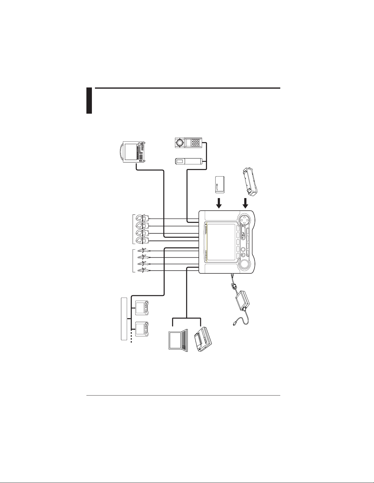
Voltage inputs
Current inputs (clamps)
CW240: synchronized measurements
using multiple instruments
External control
input/output
RS-232
PC
Printer
AC adapter
MV series: recorders
DA outputs (4 CH)
Analog inputs (2 CH)
53003
thermometer
510 series
illuminometer
PC card
Alkaline batteries
NiMH battery pack
"Chapter 13, Section 6.9"
Chapter 3
"Sections 3.3 and 3.5" "Sections 3.4 and 3.5"
Chapter 3
"3.2.1"
"Chapter 10"
"Chapter 12"
Chapter 3
"3.2.2, 3.2.3"
"Chapter 11"
"Chapter 13, Section 6.9"
External contact signal
1.2 System Configuration Diagram
1-4
IM CW240E
Page 22

Chapter 2 Part Names and How to Use Parts
Chapter 2 Part Names and How to Use
Parts
2.1 Front Panel and Connector Block ............ 2-2
2.2 Operation Keys ......................................... 2-3
2.3 Side Faces ................................................. 2-4
2.4 Screen Configuration ............................... 2-5
2.5 Overrange/Error Indication during
Measurement ............................................ 2-6
2.6 Description of Mark Indication ................ 2-11
Page 23
Chapter 2 Part Names and How to Use Parts
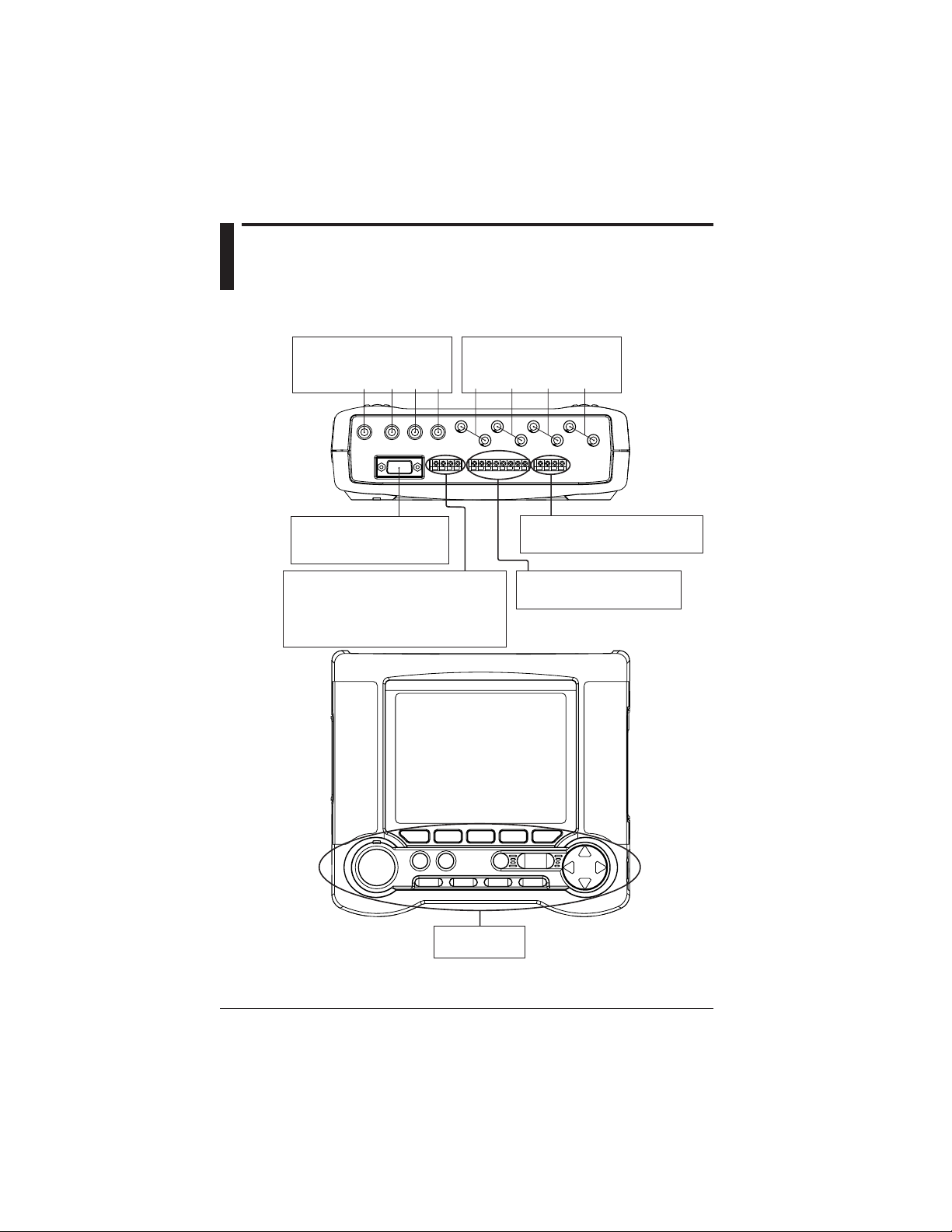
2.1 Front Panel and Connector
Block
Voltage input terminals Current input terminals
Connect the voltage
probes to these terminals.
N U1 U2 U3 CH1 CH2 CH3 CH4
Connect clamp-on current
probes to these terminals.
RS-232 connector
Connect a PC or printer using
a commercially available cable.
External control I/O terminals
Allows you start or stop integration
measurements using an external signal.
Also, a signal indicating that an integration
measurement is being made is output through
these terminals.
Display unit
Operation keys
Analog input terminals (optional)
Used for DC voltage inputs.
DA output terminals (optional)
Used for DC voltage outputs.
2-2
IM CW240E
Page 24
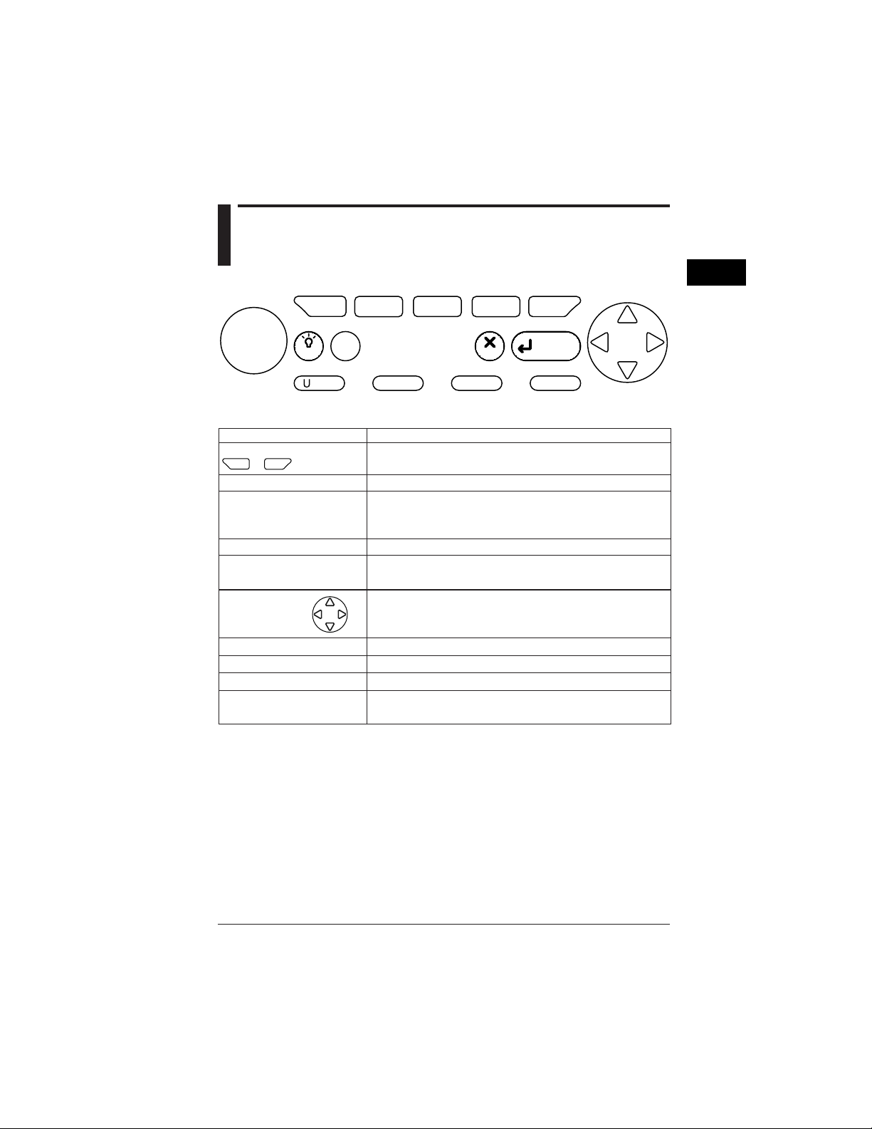
2.2 Operation Keys
F
F
F1F
1
2
3
2
Part Names and How to Use Parts
F
F
4
5
START
&STOP
Function keys
START & STOP key Starts/stops integration measurements.
LIGHT key Turns the backlight ON/OFF.
TOP MENU key Switches the display screen to the Top Menu.
ESC key
ENTER key
Cursor key Moves the cursor to the item you wish to select.
U RANGE key Changes the voltage range.
A RANGE key Changes the current range.
SAVE key Manually save or print measured data.
DISP COPY key
F
5
F
1
to
LIGHT
RANGE
TOP
MENU
RANGE
A
These are setting keys corresponding to the information displayed
in the bottom of the screen.
When held down for more than 3 seconds, it locks or unlocks the
operation keys.
Cancels setup conditions or other data.
Confirms setup conditions or other data.
Hard-copies information displayed on the screen.
Copy destination setting: PC card, internal memory, or printer
ESC
SAVE
Functional DescriptionKey Name
ENTER
DISP COPY
IM CW240E
2-3
Page 25
2.3 Side Faces
LED
Lights up while a NiMH
battery pack (optional)
is charged.
PC card slot
AC adapter jack
Connect the AC adapter
(accessorie) to this jack.
Power switch
: Power OFF
: Power ON
Button for extracting
a PC card
Battery holder
This part holds the alkaline
battery holder (accessorie) or
NiMH battery holder (optional).
2-4
Battery holder lock switch
Used to lock or unlock a
battery holder.
IM CW240E
Page 26

2.4 Screen Configuration
● Basic Screen Configuration
START
&STOP
MEASURE screen
F2 F3 F4 F5
F1
TOP
MENU
LIGHT
RANGE
RANGE
A
ENTER
ESC
SAVE
DISP COPY
SETUP screen FILE screen
2
Part Names and How to Use Parts
IM CW240E
LIST (instantaneous values)
POWER
INTEGRATE
DEMAND
ZOOM
HARMONIC
[LIST, GRAPH, VECTOR]
WAVEFORM
U & I WAVEFORM
U WAVEFORM
I WAVEFORM
VOLT. QUALITY
WIRING DIAGRAM
WIRING CHECK
GENERAL (1/2, 2/2)
SAVE (1/2, 2/2)
COMMUNICATION
VOLT. QUALITY
HARDWARE
ANALOG I/O (optional)
FILE NAME CHANGE
DELETE FILE
FORMAT
DATA COPY
SETTING FILE
BACKUP MEMORY COPY
BACKUP MEMORY DELETE
PROGRAM UPDATE
(normally not used)
2-5
Page 27
2.5 Overrange/Error Indication
during Measurement
● Overrange Indication during Measurement
: Conditions for voltage overrange indication
This mark appears if the peak value of an input signal exceeds 300%
(180% for a 1000 V range) of the rated voltage range or if the rms value of
measured voltage exceeds 110% of the rated range.
: Conditions for current overrange indication
This mark appears if the peak value of an input signal exceeds 400% of the
rated current range or if the rms value of measured current exceeds 110%
of the rated range.
TIP
• Voltage overrange mark appears if an input signal to one of terminals U1 to U3
satisfied the noted conditions.
• Current overrange mark appears if an input signal to one of terminals CH1 to
CH4 satisfies the noted conditions.
Indication of "OR" or "----" symbol
The CW240 indicates "OR" or "----" symbol instead of a usual four-digit value if
the measured value meets the noted conditions.
WARN ING
The CW240 shows an overrange mark in the maximum range only if the input
level exceeds the maximum allowable level. Do not apply any input level higher
than the maximum allowable level.
CAUTION
To measure an input signal level exceeding the rated range, use a voltage transformer (VT) or current transformer (CT).
When using a VT or CT, carefully read section 4.5, Wiring the Measurement
Circuit Using External VT/CT.
2-6
IM CW240E
Page 28
2.5 Overrange/Error Indication during Measurement
• Instantaneous value, electric energy, demand
Measurement Item Conditions and Indications
Voltage rms If the peak value of an input signal exceeds 300% (180% for
Current rms If the peak value of an input signal exceeds 400% of the
Active power
Reactive power
Apparent power
Power factor
Phase angle
Frequency
Interval electric energy
Electric energy
Reactive energy
Power demand
Reactive power demand
Analog input (optional)
the 1000 V range) of the measurement range, or if the rms
value of measured voltage exceeds 130% of the rated range,
"OR" appears.
measurement range, or if the rms value of measured current
exceeds 130% of the rated range, "OR" appears.
If power input (active, reactive, or apparent) exceeds 130%
of the rated range, "OR" appears. Also, if the measured value
exceeds the maximum displayable digits, 9999, "OR" appears.
If the peak value of a voltage input signal exceeds 300%
(180% for a 1000 V range) of the measurement range;
if the rms value of measured voltage exceeds 130% of the
rated range; if the peak value of a current input signal
exceeds 400% of the measurement range; or if the rms value
of measured current exceeds 130% of the rated range; "----"
appears.
If frequency exceeds 70 Hz, the fixed clock is selected.
Even if power input exceeds 130% of the rated range, an
excessive power value (active power, reactive power)
will be integrated. In this case, however, the accuracy of an
integrated value is not specified.
If a demand input exceeds 130% of the rated range, "OR"
appears. Also, if the measured value exceeds the maximum
displayable digits, 9999, "OR" appears.
If an input exceeds 130% of the rated range, "OR" appears.
2
Part Names and How to Use Parts
IM CW240E
2-7
Page 29

2.5 Overrange/Error Indication during Measurement
• Harmonics
Measurement Item Conditions and Indications
Voltage rms If the peak value of an input signal exceeds 300%
Voltage content
Voltage phase angle
Current rms If the peak value of an input signal exceeds 400% of the
Current content
Current phase angle
Power value If a power input exceeds 130% of the rated range,
Power content
Power phase angle
Total harmonic
distortion of voltage
Total harmonic
distortion of current
(180% for a 1000 V range) of the measurement range,
or if the rms value of measured voltage exceeds 130%
of the rated range, "OR" appears.
If the peak value of an input signal exceeds 300%
(180% for the 1000 V range) of the measurement range,
or if the rms value of measured voltage exceeds 130%
of the rated range, "----" appears.
measurement range or if the rms value of measured
current exceeds 130% of the rated range, "OR" appears.
If the peak value of an input signal exceeds 400% of the
measurement range, or if the rms value of measured
current exceeds 130% of the rated range, "----" appears.
"OR" appears.
Also, if the measured value exceeds the maximum
displayable digits, 9999, "OR" appears.
If the peak value of a voltage input signal exceeds
300% (180% for a 1000 V range) of the measurement
range; if the rms value of measured voltage exceeds
130% of the rated range; if the peak value of a current
input signal exceeds 400% of the measurement range;
or if the rms value of measured current exceeds 130%
of the rated range; "----" appears. Also, if the power
value exceeds the maximum displayable digits, 9999,
"----" appears.
If the peak value of a voltage input signal exceeds 300%
(180% for a 1000 V range) of the measurement range,
or if the rms value of measured voltage exceeds 130%
of the rated range, "----" appears.
If the peak value of a current input signal exceeds 400%
of the measurement range or if the rms value of
measured current exceeds 130% of the rated range,
"----" appears.
2-8
IM CW240E
Page 30
2.5 Overrange/Error Indication during Measurement
● Indication Provided if a Measured Value is Too Small
• Instantaneous value, electric energy, demand
Measurement Item
Voltage
Current
Active power
Reactive power
Apparent power
Electric energy
Reactive energy
Power factor
Phase angle
Frequency
Interval electric energy
Power demand
Reactive power
demand
Analog input (optional)
If an input level is below 0.4% of the rated range, the reading
becomes "0 V".
If an input level is below 0.4% of the rated range, the reading
becomes "0 A".
If an input level is 0.17% or less of the rated range, the
reading becomes "0 W".
If an input level is 0.17% or less of the rated range, the
reading becomes "0 Var".
If an input level is 0.17% or less of the rated range, the
reading becomes "0 VA".
If power input is 0.17% or less of the rated range, integration
stops.
If reactive power input is 0.17% or less of the rated range,
integration stops.
If the input level of either voltage or current is below 0.4% of
the rated range, "----" appears.
If frequency is 40 Hz or less or if the input level of a frequency
source is 10% or less of the rated range, the fixed clock is
selected, displaying the set fixed-clock frequency.
If power input is 0.17% or less of the rated range, integration
stops.
If power demand is 0.17% or less of the rated range, the
reading becomes "0 W".
If reactive power demand is 0.17% or less of the rated range,
the reading becomes "0 Var".
If an input level is below 0.4% of the rated range, the reading
becomes "0 V".
Conditions and Indications
2
Part Names and How to Use Parts
IM CW240E
2-9
Page 31

2.5 Overrange/Error Indication during Measurement
● Indications on the basis of other input conditions
Measurement Item
Electric energy
Reactive energy
Power factor
Power factor demand
Total power factor
Phase angle
Power phase angle
Reactive power
Apparent power
Legend
P : active power value
S : apparent power value
• When the display setting is any item other than AUTO, if the
integrated value exceeds "999999", the reading is reset to
"0", letting integration continue.
• When the display setting is AUTO, the position of a decimal
point or the unit of measurement is shifted by one digit to
continue integration.
Because of a computation error, if the power factor:
• Exceeds 1.0, the reading becomes "1.0."
• Is less than -1.0, the reading becomes "-1.0."
• Is S < |P|, the reading becomes "1.0."
Because of a computation error, if the power factor:
• Exceeds 1.0, the reading becomes "1.0."
• Is less than -1.0, the reading becomes "-1.0."
If the power factor exceeds 1.0 or is less than -1.0 due to a
computation error, the reading becomes "0°."
If the total power factor exceeds 1.0 or is less than -1.0 due to
a computation error, the reading becomes "0°."
Because of a computation error, if
• A value in is negative, the reading becomes "0."
• S < |P|, the reading becomes "0."
If S < |P| due to a computation error, S = |P|.
Conditions and Indications
2-10
IM CW240E
Page 32

2.6 Description of Mark Indication
Appears if a voltage overrange occurs.
Appears if a current overrange occurs.
Appears when integration measurement is made by external input control.
Appears in the event of loss of PLL synchronization. This automatically selects the
fixed clock.
Appears when a reactive power meter method is used.
Appears when display hold is enabled.
Appears if the amount of data exceeds the capacity of a PC card or the internal memory.
Appears when the CW240 is configured so that data is saved in a PC card. Also, this
mark flashes during an access to the PC card.
Appears when data has been saved in the backup memory.
Appears when the CW240 is configured so that data is saved in the internal memory.
Also, this mark flashes during an access to the internal memory.
Appears if the CW240 is in a key lock state.
Appears when the CW240 is configured so that the RS-232 connection destination is a
PC. Also, this mark flashes during communication with the PC.
Appears if the CW240 is configured so that the RS-232 connection destination is a
printer. Also, this mark flashes during communication with the printer.
Appears if the CW240 is powered through the AC adapter.
Appears when the CW240 is powered through alkaline batteries or a NiMH battery
pack. This mark indicates a battery voltage decrease (remaining capacity) in four steps.
2
Part Names and How to Use Parts
IM CW240E
2-11
Page 33

Chapter 3 Preparation for Safe Measurements
Chapter 3 Preparation for Safe
Measurements
3.1 Precautions for Use .................................. 3-2
3.2 Connecting a Power Supply ..................... 3-4
3.3 Connecting Voltage Probes .................... 3-14
3.4 Connecting Clamp-on Probes ................ 3-15
3.5 Connection Diagrams of Voltage Probes
and Clamp-on Probes ............................. 3-17
3.6 Turning ON the Power Switch ................ 3-22
3.7 Performing Measurements with Greater
Precision ................................................. 3-24
Page 34

Chapter 3 Preparation for Safe Measurements
3.1 Precautions for Use
If you are a first-time user, always read the "Precautions for Safe Use of the
CW240" on pages 6 through 11.
● Do not place any objects on the Instrument.
Do not place another device or a container filled with water on the instrument,
otherwise, the instrument may become defective.
● Moving the Instrument
Before moving the instrument, check that the power cord and all other cables
are disconnected. Hold the instrument with both hands when moving it.
● Input terminals
Do not bring a charged substance close to the signal terminals, otherwise the
internal circuitry may be destroyed. Do not apply any mechanical shock to the
signal terminals because it might be transformed into an electrical noise and
input into the instrument.
● Protection of the case or operation panel
Do not pour volatile chemicals on the case or operation panel or leave any
rubber or PVC product in contact with the case or operation panel for a
prolonged period, otherwise the case and/or operation panel may be discolored
or deformed.
3-2
● Cleaning
When cleaning the case and/or operation panel, disconnect the power cord from
the outlet and gently wipe the external surfaces with a soft clean cloth. Do not
use chemicals such as benzine or thinner, otherwise the instrument may be
discolored or deformed.
● Display screen
When the instrument is shipped from the factory, the LCD display screen is
covered with a protective film. Remove it before using the instrument.
● After use
Disconnect the power cord from the wall outlet after use.
● Long absence of use
If the instrument will not be used for a prolonged period, remove the batteries
(AA-size alkaline batteries or NiMH battery pack).
IM CW240E
Page 35

Precautions for Using Clamp-on Probes
CAUTION
3.1 Precautions for Use
• The clamping CT (current transformer) is precision assembled to ensure high
performance. When using a clamp, do not apply any intense mechanical shock,
vibration, or force to the clamping CT.
• If dust or any other foreign matter gets in the clamping CT, do not shut the
clamping cores tight. First remove dust and then make sure the clamping cores
on both sides close smoothly
3
Preparation for Safe Measurements
IM CW240E
3-3
Page 36

3.2 Connecting a Power Supply
To connect the instrument to a power supply, use the AC adapter(accessorie).
As backup power supply against a power failure, one of the following batteries
can be used. Use them together with the AC adapter.
• Alkaline batteries (accessorie)
See 3.2.2, Using Alkaline Batteries.
• NiMH battery pack (optional)
See 3.2.3, Using a NiMH (Nickel-Hydrogen) Battery Pack.
3.2.1 Connecting the AC Adapter
● Before Connecting a Power Supply
There is a danger of electrical shock or damage to the instrument. Observe the
following cautionary notes when handling the AC adapter.
WARN ING
• Use only the Yokogawa-supplied dedicated power cord.
• Check that the power source voltage matches the supply voltage rating of the
AC adapter, and then connect the power cord to the outlet.
• Check that the power switch of the CW240 is turned OFF and then connect the
power cord.
• If the CW240 is not used for a prolonged period, disconnect the AC adapter
power cord from the outlet.
• Do not use any AC adapter other than the one (part number: 788011) dedicated
to the CW240.
• Do not place any objects on the AC adapter or power cord, and do not let the
power cord come into contact with a heating element.
• Always hold the plug of the power cord rather than holding and pulling the
cord itself when disconnecting it from the outlet.
3-4
IM CW240E
Page 37

Attach the filter
to the cord.
3.2 Connecting a Power Supply
CW240 main unit
Approx. 10 cm
AC adapter
<4> Connect
<3> Connect
Clamp filter
A1193MN
<2> Connect
<1> Check that the power switch
is turned OFF.
● Procedure for Connecting the AC Adapter
Follow the steps below to connect the AC adapter.
<1> Check that the power switch of the CW240 is turned OFF.
(Attach the clamp filter to the output-side cable of the AC adapter.)
<2> Connect the AC adapter plug to the CW240's AC adapter jack.
<3> Connect the plug of the power cord supplied with the AC adapter to the
power connector of the AC adapter.
<4> Connect the other end of the power cord to the power outlet that meets the
power rating (requirements):
● AC adapter's Power Rating
Supply voltage ratin 100 to 240 V AC
Allowable supply voltage range 90 to 264 V AC
Power supply frequency rating 50/60 Hz
Allowable power supply frequency range 48 to 62 Hz
Maximum power consumption 70 to 90 VA
Output voltage rating of AC adapter 12 V DC
Maximum output current rating of AC adapter 2.6 A
3
Preparation for Safe Measurements
IM CW240E
3-5
Page 38

3.2 Connecting a Power Supply
3.2.2 Using Alkaline Batteries
NOTE
Alkaline batteries are the backup power for the AC adapter. Use them together
with the AC adapter.
Type of alkaline batteries LR6 AA-type, 1.5 V
● Handling Precautions
Observe the following cautionary notes when handling alkaline batteries.
WARN ING
• Install the alkaline batteries so that the positive and negative polarities are
correctly positioned. Otherwise, the battery fluid may leak or the batteries may
explode.
• Do not attempt to disassemble the batteries, heat them up, or dispose of them
in a fire.
• Do not short the batteries.
• Do not attempt to recharge the batteries.
• Do not solder the batteries.
• When replacing the batteries, replace all six units at the same time with new
ones (of the same manufacturer).
(Do not use manganese batteries as replacements.)
• If the CW240 will not be used for a prolonged period, remove the batteries.
3-6
● Backup Hours by Alkaline Batteries
The number of backup hours available using alkaline batteries varies with the
operating environment and conditions. Refer to the table below.
Operating Conditions Backup Hours Available
LCD backlight OFF
No access to a PC card
Approx. 30 minutes
IM CW240E
Page 39

3.2 Connecting a Power Supply
● Indication of a Battery Voltage Decrease
When the CW240 is operated using alkaline batteries, the following mark
appears. A decrease in the battery voltage (remaining capacity) is indicated in
the following four steps:
→ → →
NOTE
If you continue to operate the CW240 with this mark displayed, the
CW240 will be turned OFF automatically. Replace the alkaline
batteries with new ones before this mark appears.
3
Preparation for Safe Measurements
IM CW240E
3-7
Page 40

3.2 Connecting a Power Supply
● Procedure for Replacing Alkaline Batteries
Follow the steps below to replace alkaline batteries.
<1> Check that the power switch is OFF and no AC adapter has been
connected.
<2> Raise the battery holder lock switch at the back of the CW240 to remove
the alkaline battery holder.
<3> Remove the old batteries from the battery holder and insert six new alkaline
batteries.
<4> Place the battery holder into the holder inlet of the CW240. Then slide the
battery holder into the slot, so that the battery holder connector connects
properly with the battery connector.
<5> Lower the lock switch on the side of the CW240 to fix the holder.
(The indication changes to "䉭FREE".)
CAUTION
Place alkaline batteries into the holder with the positive (+) and negative (–)
polarities of the batteries agreeing with the polarity indications in the holder.
CW240 main unit
3-8
<1> Check that the
power switch is turned OFF.
CW240 main unit
Lock switch
<2> Remove
<3> Insert
<4>
Insert
<5> Lock
IM CW240E
Page 41

3.2 Connecting a Power Supply
3.2.3 Using a NiMH (Nickel-Hydrogen) Battery Pack
NOTE
A NiMH battery pack is backup power for the AC adapter. Use it together with
the AC adapter.
Charging type NiMH battery pack (optional) model: 94004
Specifications Voltage : 7.2 V
Capacity : 2100 mAh
Number of times chargeable (cycle life)
: approx. 300 times (depending on the operating
environment)
● Handling Precautions
Observe the following cautionary notes when handling the NiMH battery pack.
WARNI N G
• The electrolyte solution contained in the NiMH battery pack is alkaline. If it
comes into contact with any clothing or skin due to a leakage from or rupture
in the battery pack, the clothing or skin may be damaged. In particular, if the
solution gets into an eye, it may cause loss of eyesight. In such a case, do not
rub the affected eye, but thoroughly wash it immediately with clean water.
Then see a doctor quickly for treatment.
• When replacing the NiMH battery pack, always turn the CW240 power switch
OFF and disconnect the AC adapter power cord from the outlet to avoid
possible danger such as a short in the electric circuit or electrical shock.
• Do not use any battery pack other than Yokogawa's NiMH battery pack (model:
940 04).
• Do not leave the NiMH battery pack in strong direct sunlight, inside a vehicle
under the hot sun, or near a fire, otherwise it may result in a solution leakage
or deterioration in the performance and/or life.
• Do not disassemble or modify the NiMH battery pack, otherwise the protective
features of the battery pack may be damaged, resulting in a heating up or
rupture.
• Do not short the NiMH battery as this may cause burns due to the battery pack
heating up.
• Do not dispose of the battery pack in a fire or apply heat to it, otherwise there
is a risk that it will rupture or its electrolyte solution will scatter.
• Do not apply excessive shock to the battery pack, for example, by throwing it.
Doing so may cause solution leakage, battery pack heating, or rupture.
3
Preparation for Safe Measurements
IM CW240E
3-9
Page 42

3.2 Connecting a Power Supply
WARN ING
• Do not use a defective battery pack, such as any leaking solution, deformed,
discolored, or showing any other abnormality.
• Avoid any metal coming into contact with the battery pack when carrying it, as
there is a danger of a short.
• Do not immerse the battery pack in water or make it wet. Otherwise, it may
heat up or rust as well as leading to a loss of functions.
• If the battery pack is not used for a prolonged period, remove it from the CW240
and store it in the following environment.
Storage period of 1 year or less:
Temperature of -20°C to 35°C (in locations with low humidity)
Storage period of 3 months or less:
Temperature of -20°C to 45°C (in locations with low humidity)
● Procedure for Installing the NiMH Battery Pack
Follow the steps below to install the dedicated NiMH battery pack.
<1> Check that the power switch is turned OFF.
<2> If the AC adapter is in use, disconnect the power cord of the AC adapter
from the outlet.
CW240 main unit
3-10
<2> Check that the power plug
is disconnected.
AC adapter
<1> Check that the power switch
is turned OFF.
IM CW240E
Page 43

Lock switch
3.2 Connecting a Power Supply
<3> Remove
<4>
Insert
NiMH battery pack
<5> Lock
<3> If using alkaline batteries, raise the lock switch at the back of the CW240 to
remove them from the battery holder. Then install the NiMH battery pack
into the holder.
<4> Place the battery holder into the holder inlet of the CW240. Slide the battery
holder into the slot, so that the battery holder connector connects properly
with the battery connector.
<5> Lower the lock switch on the side of the CW240 to fix the holder.
(The indication changes to "䉭FREE".)
● Recharging the NiMH Battery Pack
When shipped from the factory, the dedicated NiMH battery pack (optional) is
not fully charged for safety reasons.
Recharge the battery pack to its full level before use.
When recharging it, use the CW240 and AC adapter.
WARNI N G
• When recharging the NiMH battery pack, always do so using the CW240 main
unit.
• When recharging the NiMH battery pack, keep the ambient temperature within
the range from 10°C to 35°C. Recharging the battery pack outside this range
may result in an insufficient amount of charge, solution leakage, or battery
heating.
3
Preparation for Safe Measurements
IM CW240E
3-11
Page 44

3.2 Connecting a Power Supply
● Procedure for Recharging the NiMH Battery Pack
Follow the steps below to recharge the NiMH battery pack.
<1> With the battery pack installed as instructed above, connect the AC adapter
to the CW240.
<2> The LED indicator on the side of the AC adapter jack comes on, indicating
that the battery pack is being recharged. When recharging is complete, the
LED indicator goes off.
NOTE
The NiMH battery pack will be recharged regardless of the ON/OFF of the power
switch. In this case, power is supplied through the AC adapter.
TIP
When the LED indicator is flashing, the CW240 is in a waiting-to-be-recharged state.
The CW240 falls into this state if:
• the ambient temperature is outside the 10°C to 35°C range,
• the battery performance is significantly low due to over-discharge or for other reasons,
• the battery temperature has exceeded 55°C during recharging, or
• the ambient temperature has changed abruptly.
3-12
● Indication that Recharging is Required
When the CW240 is operated using the NiMH battery pack, the following mark
appears. A decrease in the battery voltage (remaining capacity) is indicated in
the following four steps:
→ → →
NOTE
If you continue to operate the CW240 with this mark displayed, the
CW240 will be turned OFF automatically. Recharge the NiMH battery
pack before this mark appears.
IM CW240E
Page 45

3.2 Connecting a Power Supply
● Backup Hours with a NiMH Battery Pack
The number of backup hours available using a NiMH battery pack vary with the
operating environment and conditions. Refer to the table below.
Operating Conditions Backup Hours Available
LCD backlight OFF
No access to a PC card
● NiMH Battery Life
The NiMH battery pack can be recharged approximately 300 times, though the
frequency depends on the operating environment. The life of the battery pack is
over if the low-battery mark appears soon after the battery pack has been fully
recharged. Replace the battery pack with a new one.
Approx. 3 hours
3
Preparation for Safe Measurements
IM CW240E
3-13
Page 46

3.3 Connecting Voltage Probes
LL1
V INPUT
600V
MAX
TERMINALS 600V
MAX
O EAR
TH
CH
CH
CA
LOGIC NIPUT
ST
AR
T/ST
OP
5.5V MAX
LOGIC NIPUT
ST
OP
5.5V MAX
WARN ING
• For safety, connect voltage probes to the CW240 main unit and then to the
circuit under test.
• Before attaching a voltage probe to the circuit under test, turn off power to the
circuit under test. It is very dangerous to connect or disconnect a voltage
probe without turning off the circuit under test.
• Be sure to connect voltage probes to the secondary side of the circuit under
test such as current limiters (circuit breakers). Should an accident such as a
short occur, other circuits will be protected by these circuit breakers.
• Be extremely careful not to connect a voltage circuit to the current input ter-
minals or a clamp-on probe to the voltage input terminals. An improper connection may result in not only damage to the circuit or equipment under test
or the CW240, but also an injury to personnel.
• Voltage input terminals N, U1, U2, and U3 are not isolated from each other. Do
not connect any voltage probes not required (not used) for measurements.
Also, do not touch voltage input terminals not used.
• For measurements, do not use any voltage probes other than those supplied
with the product.
OP
T/ST
AR
HL H
ST
L
LOGIC NIPUT
ART/STOP
HL
ST
AX
L
5.5V M
H
H
2
CH
LOGIC NIPUT
AX
5.5V M
1
3
v
CH
L
2
v
L
1
v
TH
TO EAR
N
T.
〜 MAX
CA
TERMINALS 600V
〜MAX
600V
V INPUT
Voltage probes,
red, yellow, or blue
Voltage probe,
black (N terminal)
3-14
Insert the plug so that it is fastened
with a voltage input terminal securely.
IM CW240E
Page 47

3.4 Connecting Clamp-on Probes
LL1
V INPUT
600V
MAX
TERMINALS 600V MAX
O EAR
TH
CH
CH
CA
LOGIC NIPUT
5.5V MAX
LOGIC NIPUT
ST
OP
5.5V MAX
WARNI N G
• For safety, connect a clamp-on probe to the CW240 main unit and then to the
circuit under test.
• Before clamping a clamp-on current probe onto the circuit under test, turn off
power to the circuit under test. It is very dangerous to clamp or unclamp the
clamp-on probe without turning off the circuit under test.
• Be sure to connect a clamp-on probe to the secondary side of the circuit under test such as current limiters (circuit breakers). Should an accident such
as a short occur, other circuits will be protected by these circuit breakers.
• Be extremely careful not to connect a voltage circuit to the current input terminals or a clamp-on probe to the voltage input terminals. An improper connection may result in not only damage to the circuit or equipment under test
or the CW240, but also an injury to personnel.
• Do not connect any clamp-on probe not required (not used) for measurement.
• For measurements, do not use any current probes other than those dedicated
to the CW240.
• Do not use a clamp-on probe for a non-insulated conductor.
Ring markers
<1>
<2>
Clamp-on current probe
START/STOP
L H
LOGIC NIPUT
L H
ART/STOP
HL H
ST
X
A
L
.5V M
5
H
2
CH
LOGIC NIPUT
X
A
5.5V M
1
3
v
CH
L
2
v
L
1
v
TH
R
N
TO EA
AX
T.
CA
600V M
ALS
IN
ERM
AX
T
M
0V
60
V INPUT
3
Preparation for Safe Measurements
● Use of Ring Markers
• When using multiple clamp-on probes, attach ring markers (four colors) to the
probes. This allows inputs to be identified. Attach ring markers of the same
color to the current probe side <1> and connector side <2> of the cable of a
clamp-on probe.
• When attaching ring markers, exercise care not to damage the clamp-on
probes.
IM CW240E
3-15
Page 48

3.4 Connecting Clamp-on Probes
● Connecting Clamp-on Probes
When connecting a clamp-on probe to the CW240 main unit, connect the plug of
the clamp-on probe so that the groove in the plug agrees with the guide in the
CW240 main unit (that the H and L polarities are correctly connected).
● Types of Clamp-on Probes
Clamp-on probes that can be connected to the CW240 are available in the
following seven types. The CW240's current range setting changes depending
on the clamp-on probes in use.
Model
96036 (for 2 A)
96033 (for 50 A)
96030 (for 200 A)
96031 (for 500 A)
96032 (for 700 A)
1000 A (for 5 minutes)
96034 (for 3000 A)
96034-1
96034_2
96034_3
96035 (for 3000 A)
96035_1
96035_2
CW240 Current Range
200 mA/500 mA/1 A/2 A
5 A/10 A/20 A/50 A
20 A/50 A/100 A/200 A
50 A/100 A/200 A/500 A
200 A/500 A/1000 A
Current range is selectable using a switch.
300 A/750 A/1500 A/3000 A
200 A/500 A/1000 A/2000 A
100 A/200 A/500 A/1000 A
Current range is selectable using a switch.
300 A/750 A/1500 A/3000 A
30 A/75 A/150 A/300 A
CAUTION
When connecting a clamp-on probe, always check that the rating of the current
under test agrees with the rating of the clamp-on probe, including model number check.
3-16
IM CW240E
Page 49

3.5
Connection Diagrams of Voltage
Probes and Clamp-on Probes
Single-phase two-wire/Single load
(1P2W)
N1
Black
Red
Single-phase two-wire/Three loads
(1P2W)
N1
Black
Red
Load 1
Load 1 Load 2 Load 3
Single-phase two-wire/Two loads
(1P2W)
N1
Black
Single-phase two-wire/Four loads
(1P2W)
N1
Black
Load 1 Load 2
Red
Load 2 Load 3
Load 1 Load 4
Red
3
Preparation for Safe Measurements
IM CW240E
3-17
Page 50

3.5 Connection Diagrams of Voltage Probes and Clamp-on Probes
Single-phase three-wire/Single load
(1P3W)
N12
Black
Red
Yellow
Load 1 Load 2
Single-phase three-wire three-current
(1P3W3I)
<Measurement of neutral line current>
N12
Black
Red
Yellow
12 N
Single-phase three-wire/Two loads
(1P3W)
Load 1 Load 2
N12
Black
Red
Yellow
1212
3-18
IM CW240E
Page 51

3.5 Connection Diagrams of Voltage Probes and Clamp-on Probes
Three-phase three-wire two-current/
Single load (3P3W2I)
<Two-power-meter method>
SR T
Black
Red
RT
Blue
Three-phase three-wire two-current/
Two loads (3P3W2I)
<Two-power-meter method>
Load 1 Load 2
SR T
Black
Red
RTRT
Blue
3
Preparation for Safe Measurements
Three-phase three-wire three-current
(3P3W3I)
<Three-power-meter method>
RST R S T
Red
Yellow
Blue
IM CW240E
3-19
Page 52

3.5 Connection Diagrams of Voltage Probes and Clamp-on Probes
Three-phase four-wire (3P4W)
N1 32
Black
Red
Yellow
123
Blue
Three-phase four-wire four-current
(3P4W4I)
<Measurement of neutral line current>
N1 32
Black
Red
Yellow
123N
Blue
3-20
IM CW240E
Page 53

3.5 Connection Diagrams of Voltage Probes and Clamp-on Probes
Scott connection (3P3W+1P3W)
Single-phase (1P3W) connection: R-S
3
Preparation for Safe Measurements
Scott connection (3P3W+1P3W)
Single-phase (1P3W) connection: S-T
Three-phase
3-wire
NR TS
Black
Red
Single phase
1 (R)2 (S)R T
Yellow
Blue
Scott connection (3P3W+1P3W)
Single-phase (1P3W) connection: T-R
Three-phase
3-wire
NR TS
Black
Red
Single phase
1 (T)2 (R)R T
Yellow
Blue
NR TS
Black
Red
Single phase
1 (S)2 (T)R T
Yellow
Blue
Three-phase
3-wire
IM CW240E
3-21
Page 54

3.6 Turning ON the Power Switch
[ 1 Model Name Screen
When the power switch is turned ON, the CW240 displays the following startup screen for
approx. 2 seconds.
2 Message Screen
This screen displays the model, version number, the presence of options, and self-check
results.
CW240 Ver 1.00
FPGA Check OK
SDRAM Check OK
SRAM Check OK
Flash Disk Check OK
RTC Check OK
EEPROM Check OK
Setting Check OK
Option:Analog In/Out
3 When the self-check has been completed normally, the screen displayed when
you previously turned OFF the CW240 appears.
To switch to the Top Menu screen shown
on the left, press the TOP MENU key.
TOP
key
MENU
3-22
IM CW240E
Page 55

3.6 Turning ON the Power Switch
● Description of the Message Screen
Indications
1 CW240 VER 1.00
Self-check
2 FPGA Check OK
3 SDRAM Check OK
4 SRAM Check OK
5 Flash Disk Check OK
6 RTC Check OK
7 EEPROM Check OK
8 Setting Check OK
9 Option:Analog In/Out
Model and version number
FPGA check
SDRAM check
SRAM check
Check of the flash file system (internal memory)
Check of the real-time clock
EEPROM Check
Setting data check
Option specifications
The example shows the presence of analog I/O.
Description
CAUTION
If an error is detected by the self-check (3 to 8 items), the information about the
error is displayed. For countermeasures, see Chapter 16, Maintenance Troubleshooting.
3
Preparation for Safe Measurements
IM CW240E
3-23
Page 56

3.7 Performing Measurements
with Greater Precision
• After turning the power switch on, let the CW240 warm up (for more than 30
minutes) before starting to perform measurements.
• To perform measurements with higher precision, use the CW240 under the
following environment conditions:
Ambient temperature: 23 ± 5°C
Ambient humidity: 35 to 75% R.H (no condensation)
If the CW240 is installed in a location where the ambient humidity is less than
30%, use an antistatic mat, etc. to prevent electrostatic discharge.
If you move the CW240 from a location of low temperature and humidity to a
location of high temperature and humidity or, if there is an abrupt change in
the ambient temperature, condensation may occur in the CW240. If this
happens, let the CW240 stand still for at least an hour to allow it to adapt to
the new ambient temperature and for any condensation to dissolve. Then
begin operating the CW240.
• Supply the power of sine waves at 50 Hz/60 Hz.
• When using a clamp-on probe, pay attention to the following points:
<1> When performing measurements, hold the clamp-on probe so that the
conductor cable runs through the center of the clamping CT.
<2>
Ensure that the orientation of the clamp to the direction of the conductor
cable (from the power supply to the load) is correct, as shown on the right.
<3> Ensure that the clamping CT is properly closed.
Power supply side
Conductor cable
(SOURCE)
Joint section
Clamping CT
Load side
(LOAD)
TIP
The CW240 obtains the measured value from voltage and current inputs.
(For computation equations, see Chapter 17, CW 240 Specifications.)
There may be cases where the CW240 shows a measurement value different from
those obtained by other equipment with different operation principles or computation
equations.
3-24
IM CW240E
Page 57

Chapter 4 Wiring
Chapter 4 Wiring
4.1 Precautions for Wiring
to the Measurement Circuit ...................... 4-2
4.2 Installing the CW240 ................................. 4-3
4.3 Setting up Wiring ...................................... 4-5
4.4 Setting up the Number of Loads .............. 4-6
4.5 Carrying out Wiring .................................. 4-7
4.6 Wiring the Measurement Circuit
Using External VT/CT.............................. 4-23
4.7 Checking Wiring ..................................... 4-24
Page 58

Chapter 4
4.1 Precautions for Wiring to
the Measurement Circuit
WARN ING
• Before carrying out wiring, be sure to read through 3.3, Connecting Voltage
Probes, and 3.4, Connecting Clamp-on Probes.
• Do not apply an input exceeding the following value to the voltage input
terminals.
Maximum allowable input : 1000 V rms
For measurement category III : 600 V rms
• The maximum allowable input and maximum operating circuit voltage of the
clamp-on probes are as specified in the table below. Do not apply an input
exceeding the relevant value or use the CW240 at a circuit voltage
exceeding it.
Model Current Rating
96036 2 A 20 A 50 V/CAT.III
96033 50 A 60 A 300 V/CAT.III
96030 200 A 250 A 300 V/CAT.II, 600 V/CAT.II
96031 500 A 625 A 300 V/CAT.II, 600 V/CAT.II
96032 700 A (continuous) 700 A (continuous) 600 V
1000 A (for 5 min) 1000 A (for 5 min)
96034 1000/2000/3000 A 2400 A (continuous) 600 V/CAT.III
96035 300/3000 A 360/360 A 1000 V/CAT.III (area to be measured)
Maximum
Allowable Input
3600 A (for 10 min)
Maximum Operating Circuit Voltage/
Measurement Category
SEE ALSO
For more information, see Chapter 17, CW 240 Specifications.
WARN ING
• If using an external VT (voltage transformer) or CT (current transformer), make
sure the transformer can sufficiently withstand the voltage to be measured.
• Be careful not to allow the secondary side of CT to become open-circuited
while the CT is being energized. Otherwise, a high voltage may develop on the
secondary side, posing extreme risks.
4-2
IM CW240E
Page 59

4.2 Installing the CW240
Install the CW240 in locations meeting the following conditions:
● Location
Indoor
● Ambient Temperature and Humidity
• Ambient temperature : 5°C to 40°C
• Ambient humidity : 5 to 85% R.H
(no condensation)
● Operating Altitude
• 2000 m max. above sea level
● Measurement Category (CAT.)
The measurement category of the CW240 is III.
4
Wiring
Measurement
category
II
CAT.II
CAT.IIIIII
CAT.IV
IV
For measurements performed
on circuits directly connected
to the low voltage installation.
For measurements performed
in the building installation.
For measurements performed
at the source of the low-voltage
installation.
DescriptionRemarks
Appliances, portable
equipments, etc.
Distribution board, circuit
breaker, etc.
Overhead wire, cable
systems, etc.
Internal Wiring
T
Entrance
Cable
IV
III
Outlet
II
IM CW240E
4-3
Page 60

4.3 Installing the CW240
● Installation Category (CAT.)
The installation category of the CW240 is III.
Instrallation
Category
CAT.II
II
CAT.III
III
CAT.IV
IV
● Pollution degree
The pollution degree of CW240 is 2.
“Pollution degree” describes the degree to which a solid, liquid, or gas which
deteriorates dielectric strength or surface resistivity is adhering.
“2” applies to normal indoor atmosphere. Normally, only non-conducitve
pollution occurs. Occasionally, however, temporary conductivity caused by
condensation must be expected.
● Level Location
Do not install the CW240 in an unstable or inclined location. Otherwise, it may
fail to achieve precision measurements.
Description
Applies to electrical equipment wihch is supplied form the
fixed installation like distribution board.
Applies to electrical equipment which is power-supplied from
a cable way ranging from the primary stage and branch point
of equipment directly introducing electricity form a distribution
board to the wall outlet.
Applies to electrical equipment which is power-supplied form
a cable way ranging from the entrance cable of a building to
a primary overcurrent protection.
● Do not install the CW240 in a location that is:
• exposed to direct sunlight or close to a heat source,
• close to a noise source such as high-voltage equipment or a motive power
supply,
• exposed to a relatively large amount of lampblack, steam, dust, corrosive
gas,
• exposed to frequent mechanical vibration,
• close to a source of strong electromagnetic fields, or
• unstable.
WARN ING
• When using multiple CW240s, provide a space of at least 10 mm between the
meters.
• If the CW240 is installed in a switchboard, etc., provide a space of at least
10 mm from the wall. Also, provide space for wiring sections of terminals, etc.
in consideration of protrusions such as plugs.
4-4
IM CW240E
Page 61

4.3 Setting up Wiring
Wiring can be set up on the GENERAL 1/2 screen.
● General 1/2
TOP
MENU
ENTER
F2F3F4F
F
1
ENTER
START
&STOP
TOP
MENU
LIGHT
RANGE
RANGE
A
ENTER
ESC
SAVE
DISP COPY
● Changing Wiring
1 Using the Up and Down cursor key, select WIRING (highlighted).
2 Press the F1 key (CHANGE).
F1F
1
The wiring selection window appears.
3P3W+1P3W
3P4W4I
3P4W
3P3W3I
3P3W2I
1P3W3I
1P3W
1P2W
Scott connection
Three-phase four-wire four-current
Three-phase four-wire
Three-phase three-wire three-current
Three-phase three-wire two-current (Default)
Single-phase three-wire three-current
Single-phase three-wire
Single-phase two-wire
4
Wiring
5
3 Press the ENTER key.
ENTER
This causes the wiring selection window to close, bringing you to the
GENERAL screen.
The selected wiring is indicated.
SEE ALSO
For more information on settings, see Section 6.2, General Settings 1/2, in Chapter 6,
Configuring Settings.
IM CW240E
4-5
Page 62

4.4 Setting up the Number
of Loads
The number of loads can be set up on the GENERAL 1/2 screen.
● General 1/2
TOP
MENU
ENTER
ENTER
START
&STOP
F2F3F4F
F
1
TOP
MENU
LIGHT
RANGE
RANGE
A
ESC
SAVE
5
ENTER
DISP COPY
● Changing the Number of Loads
1 Using the Up and Down cursor key, select LOAD (highlighted).
The function key labels change.
Load 1 Load 2 Load 3 Load 4
F
F
F1F
1
F
2
3
4
F
5
Default: Load 1
2 Set the number of loads using the corresponding function key.
F1F
1
to
F4
● For Scott Connections
If wiring is set to 3P3W+1P3W(Scott connection), the setting of 1P connection is
displayed (instead of the number of loads).
SEE ALSO
For more information on settings, see Section 6.2, General Settings 1/2, in Chapter 6,
Configuring Settings.
4-6
IM CW240E
Page 63

4.5 Carrying out Wiring
L
V INPUT
600V MAX
TERMINALS 600V MAX
O EAR
TH
CH
CH
CA
LOGIC NIPUT
ST
AR
T/ST
OP
5.5V MAX
LOGIC NIPUT
ST
AR
T/ST
OP
5.5V MAX
WARNI N G
• When attaching voltage probes to or clamping a clamp-on probe on the circuit
under test, turn off power to the circuit under test.
It is very dangerous to connect or disconnect a voltage probe or clamp or
unclamp a clamp-on probe without turning off the circuit under test.
• Be sure to connect voltage probes to or clamp a clamp-on probe on the secondary side of the circuit under test, such as current limiters (circuit breakers). Should an accident such as a short occur, other circuits will be protected
by these circuit breakers.
Power supply
side
Circuit breaker
Orientate the clamp-on
probe so that the
arrows on the clamping
CT faces the correct
direction.
Power supply side
Clip voltage probes securely onto
metal parts such as screws or
wiring bars.
OP
T/ST
AR
H
ST
L
H
LOGIC NIPUT
OP
L
T/ST
AR
H
ST
L
5.5V MAX
H
H
2
L
CH
5.5V MAX
1
3
v
CH
L
L
TH
TO EAR
LOGIC NIPUT
2
v
1
v
TERMINALS 600V MAX
T
600V MAX
V INPU
4
Wiring
N
T.
CA
Direction marks
Load side
Load side
IM CW240E
4-7
Page 64

4.5 Carrying out Wiring
4.5.1 Single-phase Two-wire / Single Load (1P2W)
● WIRING DIAGRAM Screen ● WIRING CHECK Screen
● Actual Wiring
I
Power
supply
N
Black
Red
SEE ALSO
For more information on wiring checks, see Section 4.7, Checking Wiring.
I
Load
N
4-8
IM CW240E
Page 65

4.5 Carrying out Wiring
4.5.2 Single-phase Two-wire / Two Loads (1P2W)
The CW240 can simultaneously measure multiple loads of the same power
supply (voltage shared).
● WIRING DIAGRAM Screen ● WIRING CHECK Screen
● Actual Wiring
4
Wiring
I
Power
supply
N
Black
Red
SEE ALSO
For more information on wiring checks, see Section 4.7, Checking Wiring.
I
Load
1
N
I
Load
2
N
IM CW240E
4-9
Page 66

4.5 Carrying out Wiring
4.5.3 Single-phase Two-wire / Three Loads (1P2W)
The CW240 can simultaneously measure multiple loads of the same power
supply (voltage shared).
● WIRING DIAGRAM Screen ● WIRING CHECK Screen
● Actual Wiring
I
Power
supply
N
Black
Red
SEE ALSO
For more information on wiring checks, see Section 4.7, Checking Wiring.
I
Load
1
N
I
Load
N
2
I
Load
N
3
4-10
IM CW240E
Page 67

4.5 Carrying out Wiring
4.5.4 Single-phase Two-wire / Four Loads (1P2W)
The CW240 can simultaneously measure multiple loads of the same power
supply (voltage shared).
● WIRING DIAGRAM Screen ● WIRING CHECK Screen
● Actual Wiring
4
Wiring
I
Power
supply
N
Black
Red
SEE ALSO
For more information on wiring checks, see Section 4.7, Checking Wiring.
I
Load
1
N
I
Load
N
2
I
Load
N
3
I
Load
4
N
IM CW240E
4-11
Page 68

4.5 Carrying out Wiring
4.5.5 Single-phase Three-wire / Single Load (1P3W)
● WIRING DIAGRAM Screen ● WIRING CHECK Screen
● Actual Wiring
I
N
Power
supply
22
Black
Red
Yellow
SEE ALSO
For more information on wiring checks, see Section 4.7, Checking Wiring.
I
N
Load
4-12
IM CW240E
Page 69

4.5 Carrying out Wiring
4.5.6 Single-phase Three-wire / Two Loads (1P3W)
The CW240 can simultaneously measure multiple loads of the same power
supply (voltage shared).
● WIRING DIAGRAM Screen ● WIRING CHECK Screen
● Actual Wiring
4
Wiring
I
N
Power
supply
22
Black
Red
Yellow
SEE ALSO
For more information on wiring checks, see Section 4.7, Checking Wiring.
I
N
Load
1
I
N
Load
2
2
IM CW240E
4-13
Page 70

4.5 Carrying out Wiring
4.5.7 Single-phase Three-wire Three-current (1P3W3I)
<Measurement of neutral line current>
● WIRING DIAGRAM Screen ● WIRING CHECK Screen
● Actual Wiring
I
N
Power
supply
22
Black
Red
Yellow
SEE ALSO
For more information on wiring checks, see Section 4.7, Checking Wiring.
I
N
Load
4-14
IM CW240E
Page 71

4.5 Carrying out Wiring
4.5.8 Single-phase Three-wire Two-current / Single Load
(3P3W2I)
<Two-power-meter method>
● WIRING DIAGRAM Screen ● WIRING CHECK Screen
● Actual Wiring
4
Wiring
Power
supply
1R
2S
3T
Black
Red
Blue
1R
2S
3T
SEE ALSO
For more information on wiring checks, see Section 4.7, Checking Wiring.
Load
IM CW240E
4-15
Page 72

4.5 Carrying out Wiring
4.5.9 Single-phase Three-wire Two-current / Two Loads
(3P3W2I)
<Two-power-meter method>
The CW240 can simultaneously measure multiple loads of the same power
supply (voltage shared).
● WIRING DIAGRAM Screen ● WIRING CHECK Screen
● Actual Wiring
1R
Power
supply
2S
3T
Black
Red
Blue
SEE ALSO
For more information on wiring checks, see Section 4.7, Checking Wiring.
4-16
1R
2S
3T
1R
2S
3T
Load
1
Load
2
IM CW240E
Page 73

4.5 Carrying out Wiring
4.5.10 Three-phase Three-wire Three-current (3P3W3I)
<Three-power-meter method>
● WIRING DIAGRAM Screen ● WIRING CHECK Screen
● Actual Wiring
4
Wiring
Power
supply
1R
2S
3T
Black
Red
Blue
1R
2S
3T
NOTE
Do not connect a wire to terminal N of the voltage input terminals.
SEE ALSO
For more information on wiring checks, see Section 4.7, Checking Wiring.
Load
IM CW240E
4-17
Page 74

4.5 Carrying out Wiring
4.5.11 Three-phase Four-wire (3P4W)
● WIRING DIAGRAM Screen ● WIRING CHECK Screen
● Actual Wiring
Power
supply
1R
2S
3T
Black
Red
Yellow
Blue
1R
2S
3T
SEE- ALSO
For more information on wiring checks, see Section 4.7, Checking Wiring.
Load
NN
4-18
IM CW240E
Page 75

4.5 Carrying out Wiring
4.5.12 Three-phase Four-wire Four-current (3P4W4I)
<Measurement of neutral line current>
● WIRING DIAGRAM Screen ● WIRING CHECK Screen
● Actual Wiring
4
Wiring
1R
2S
3T
NN
Power
supply
1R
2S
3T
Black
Red
Yellow
Blue
SEE ALSO
For more information on wiring checks, see Section 4.7, Checking Wiring.
Load
IM CW240E
4-19
Page 76

4.5 Carrying out Wiring
4.5.13 Scott Connection (3P3W+1P3W)
Single phase (1P3W) connection: R-S
● WIRING DIAGRAM Screen ● WIRING CHECK Screen
● Actual Wiring
1R
2S
3T
1
N
2
Power
supply
1R
2S
3T
N
Black
Red
Yellow
Blue
SEE ALSO
For more information on wiring checks, see Section 4.7, Checking Wiring.
Three-phase,
3-wire
Load
Single-phase,
3-wire
Load
4-20
IM CW240E
Page 77

4.5 Carrying out Wiring
4.5.14 Scott Connection (3P3W+1P3W)
Single phase (1P3W) connection: S-T
● WIRING DIAGRAM Screen ● WIRING CHECK Screen
● Actual Wiring
4
Wiring
1R
2S
3T
I
N
2
Power
supply
1R
2S
3T
N
Black
Red
Yellow
Blue
SEE ALSO
For more information on wiring checks, see Section 4.7, Checking Wiring.
Three-phase,
3-wire
Load
Single-phase,
3-wire
Load
IM CW240E
4-21
Page 78

4.5 Carrying out Wiring
4.5.15 Scott Connection (3P3W+1P3W)
Single phase (1P3W) connection: T-R
● WIRING DIAGRAM Screen ● WIRING CHECK Screen
● Actual Wiring
1R
2S
3T
I
N
2
Power
supply
1R
2S
3T
N
Black
Red
Yellow
Blue
SEE ALSO
For more information on wiring checks, see Section 4.7, Checking Wiring.
Three-phase,
3-wire
Load
Single-phase,
3-wire
Load
4-22
IM CW240E
Page 79

4.6 Wiring the Measurement
Circuit Using External VT/CT
WARNI N G
• When using an external CT, be careful not to allow the secondary side of the
CT to become open-circuited while the primary side is being energized,
otherwise, a high voltage may develop on the secondary side, posing extreme
risks.
• The current under test flows though the thick lines shown in the figure below.
For these, use wires that have an adequate margin of current-carrying
capacity.
If the maximum voltage or current level of the circuit under test exceeds the
maximum measurement range of the CW240, use an external VT and/or CT.
This strategy enables the measurement of the voltage or current level.
Example of Single-phase 2-wire (1P2W)
Power supply
1
N
(voltage transformer)
VT
V
v
Load
L
CT
(current transformer)
艎
4
Wiring
TIP
• If using VT and/or CT, setting the VT ratio and/or CT ratio allows the CW240 to
display the primary-side value.
• When the secondary side of the CT is rated at 5 A, it is recommended that the 96033
(for 50 A) clamp-on probe be used in the 5 A range.
SEE ALSO
For how to set a VT or CT ratio, see 6.2.7, Setting Up VT Ratio and CT Ratio.
IM CW240E
4-23
Page 80

4.7 Checking Wiring
WARN ING
Checking wiring is important for ensuring safe and accurate measurements.
Refer to Chapters 3 and 4 to carry out the necessary precautions for safe
measurement and ensure that the connections have been made correctly.
Check that the connections of the voltage probes and the connector H/L
orientation and measurement positions of the clamp-on probe are
correct.
• Press the F1 key (DISPLAY CHANGE) on the MEASURE screen to select the
WIRING CHECK screen.
• The following item is indicated on WIRING CHECK screen.
Rms value of voltage input and Current input, and phase angle and vector
diagram related to U1.
<Measured value display>
Voltage(rms):U1
Phase angle
(relative to U1)
Current(rms):I1
vector diagram
displayed
Phase angle
(relative to U1)
4-24
F
2
F1F
1
F
3F4
F
5
<Judgment result display>
Judgment result
F2
F1F1
F3 F4
F5
Use the F3 key to switch between the measured value and judgment
result displays.
To change the wiring to 3P3W+1P3W (Scott connection), press the F4 key to
display the connection destination of a single-phase load.
IM CW240E
Page 81

4.7 Checking Wiring
NOTE
• As the CW240 performs a wiring check based on the conditions shown below
to judge if the wiring is accepted (OK) or rejected (NG), there may be cases
where the result of the check may show what is actually correct wiring as NG
and vice versa.
For this reason, also check for an error in the vector diagram or measured
values.
• The rms values, phase angles, and vector diagram displayed are based on the
fundamental components of voltage and current inputs.
● Wiring Check Items and Error Conditions - 1
Item
Voltage input
Current inpu
Phase difference
(voltage - current)
Voltage phase
10% or less of the rated range
1% or less of the rated range For 1P3W3I or 3P4W4I,
I4 is not judged.
• The result of voltage input judgment is NG.
• For any system other than 3P3W2I or 3P3W3I:
Each current does not fall within a range of ±60° based
on each phase voltage
• For 3P3W2I:
I1 does not fall within a range of +90° to -30° relative to U1
I3 dose not fall within a range of +90° to -30° relative to U2
• For 3P3W3I:
Each current does not fall within a range of +90° to -30°
based on each phase voltage
• For Scott connections:
A combination of single-phase 3-wire and three-phase
3-wire 2-current
• The result of voltage input judgment is NG.
• For 1P3W or 1P3W3I:
U2 does not fall within a range of 180° ±20% with
respect to U1.
• For 3P3W2I:
U2 leads U1 and does not fall within a range of 60°
(leading)
• For 3P3W3I, 3P4W, or 3P4W4I:
U2 lags behind U1 and does not fall within a range of
120°(lagging) ± approx. 20° relative to U1, or U3 leads
U1 and does not fall within a range of 120°(leading)
± approx. 20° relative to U1.
Error Conditions
± approx. 20° relative to U1.
4
Wiring
IM CW240E
4-25
Page 82

4.7 Checking Wiring
● Wiring Check Items and Error Conditions - 2
Item
Current phase
Frequency source
Scott connection
Error Conditions
• The result of current input judgment is NG.
• For 3P3W2I:
The phase of I3 lags behind that of I1.
• For 3P3W3I, 3P4W, or 3P4W4I:
The phase of I3 lags behind that of I1 or the phase of I2
leads that of I1.
• Frequency measurement is unstable.
• Input frequency is 40 Hz or less, or 70 Hz or more.
When the connection setting of a single-phase, 3-wire
load is set to:
• R-S phase,
V1n+V2n = 10% or more of voltage rating
• S-T phase,
V2n+V3n = 10% or more of voltage rating
• T-R phase,
V3n+V1n = 10% or more of voltage rating
4-26
IM CW240E
Page 83

4.7 Checking Wiring
● If the results of one or more wiring check are NG, check the following:
Results
Voltage input judgment
is NG.
Current input judgment
is NG.
Phase difference judgment
(voltage - current) is NG.
Voltage phase judgment
is NG.
Current phase judgment
is NG.
Frequency source check
is NG.
Scott connection check
is NG.
•
Check if the voltage probes are connected properly to
the circuit under test.
•
Check if the voltage probes are connected properly to
the voltage input terminals of the product.
•
Check if the voltage range is appropriate to the input level.
• Check if the clamp-on probe(s) is clamped onto
the circuit under test properly.
• Check if clamp-on probe(s) is connected to the
current input terminal of the product properly.
• Check if the current range is appropriate to the input
level.
• Check if the voltage phase sequence is correct.
• Check if the direction of the arrows and the phase of
the clamp-on probe(s) are correct.
• Check if the voltage phase sequence is correct.
• Check if the circuit under test and the setting of the
wiring system agree with each other.
• Check if the direction of the arrows and the phase of
the clamp-on probe(s) are correct.
• Check if the circuit under test and the setting of the
wiring system agree with each other.
• Check if the voltage input selected for the frequency
source is stable.
• Check if the voltage probes selected for the frequency
source are connected properly.
• Check if the connection setting of the single-phase
3-wire load agrees with the circuit under test in the
Scott connection.
• Check if the voltage phase sequence is correct.
Measures
4
Wiring
IM CW240E
4-27
Page 84

Chapter 5 Setting Ranges Using the Direct Keys
Chapter 5 Setting Ranges Using the
Direct Keys
5.1 Setting the Voltage Range ........................ 5-2
5.2 Setting the Current Range ........................ 5-4
5.3 Ranges and Number of Digits .................. 5-6
Page 85

Chapter 5 Setting Ranges Using the Direct Keys
5.1 Setting the Voltage Range
F2 F 3 F 4 F 5
F1
START
&STOP
LIGHT
[ 1 Voltage Range Direct Key
RANGE
Press the U RANGE key once.
This causes the voltage range indication to be highlighted, changing the
function key labels to voltage ranges.
RANGE
TOP
MENU
A
RANGE
ENTER
ESC
SAVE
DISP COPY
150V 300V 600V 1000V
F
F
F1F
1
F
2
3
4
Default: 150 V
2 Setting the Voltage Range
F1F
1
to F4 Press the corresponding function key to set the voltage range.
The voltage range changes to the selected one, returning the screen to the
MEASURE screen.
TIP
If you do not want to change the voltage range, press the U RANGE key again or
press the ESC key once. This causes the screen to return to the MEASURE screen.
5-2
F
5
IM CW240E
Page 86

5.1 Setting the Voltage Range
NOTE
If the result of "power rating ⫻ VT ratio ⫻ CT ratio ⫻ 1.3" exceeds 999.9 TW, the
voltage range cannot be changed. To change the voltage range in this case,
modify other settings (wiring, current range, clamp-on probe type, VT ratio, and/
or CT ratio) and then change it.
TIP
• A voltage range cannot be set during integration measurement (including when on
standby).
• A voltage range cannot be set in the VOLT. QUALITY or WIRING DIAG. screen.
• If integral measured data has not been cleared, the voltage range cannot be set.
To change the voltage range in this case, press the F5 key (HOLD/CLEAR) for more
than 3 seconds on the MEASURE screen to clear integral measured data and then
change it.
5
Setting Ranges Using the Direct Keys
IM CW240E
5-3
Page 87

5.2 Setting the Current Range
F2 F 3 F 4 F 5
F1
START
&STOP
LIGHT
[ 1 Current Range Direct Key
A
RANGE
Press the A RANGE key once.
This causes the current range indication to be highlighted, changing the
function key labels to current ranges.
(The contents of the function key labels vary depending on the clamp-on
probe to be used.)
20A 50A 100A 200A
F1F
1
Default: 20 A (when clamp-on probe 96030 has been set)
The default is the minimum range of each clamp-on probe.
RANGE
TOP
MENU
RANGE
A
F
2
ENTER
ESC
SAVE
DISP COPY
F
F
3
4
F
5
2 Setting the Current Range
F4
F1F
1
to
Press the corresponding function key to set the current range.
The current range changes to the selected one, returning the screen to the
MEASURE screen.
TIP
If you do not want to change the current range, press the A RANGE key again or press
the ESC key once. This causes the screen to return to the MEASURE screen.
5-4
IM CW240E
Page 88

5.2 Setting the Current Range
● Types of Clamp-on Probes and Current Ranges
Models of Clamp-on
Probes
96036 200mA 500mA 1A 2A
96033 5A 10A 20A 50A
96030 20A 50A 100A 200A
96031 50A 100A 200A 500A
96032 200A 500A 1000A
96034_1 300A 750A 1500A 3000A
96034_2 200A 500A 1000A 2000A
96034_3 100A 200A 500A 1000A
96035_1 300A 750A 1500A 3000A
96035_2 30A 75A 150A 300A
96034 or 96035: Current range is selected using the switch on a clamp-on current probe.
F1 F2 F3 F4
Function Keys
NOTE
• The current ranges to be selected differ depending on the clamp-on current
probe to be used.
• For measurements of multiple loads, a current range can be set for each load.
For this, press the F2 key (LOAD CHANGE) to select the load for which you
wish to change the current range and then set the current range.
• If the wiring system is 1P3W3I or 3P4W4I, you cannot use the A RANGE key to
set the current range of I4. To set this current range, move to the SETUP screen
and then set it.
• If the wiring system is a Scott connection, a current range can be set
separately for the three-phase three-wire and single-phase three-wire sides.
For this, press the F2 key (3P3W or 1P1W) to select the wiring for which you
wish to change the current range and then set the current range.
• If the result of "power rating ⫻ VT ratio ⫻ CT ratio ⫻ 1.3" exceeds 999.9 TW,
the current range cannot be changed. To change the current range in this case,
modify other settings (wiring, voltage range, clamp-on probe type, VT ratio,
and/or CT ratio) and then change it.
5
Setting Ranges Using the Direct Keys
TIP
• A current range cannot be set during integration measurement (including when on
standby).
• A current range cannot be set in the VOLT. QUALITY or WIRING DIAG. screen.
• If integral measured data has not been cleared, the current range cannot be changed.
To change the current range in this case, press the F5 key (HOLD/CLEAR) for more
than 3 seconds on the MEASURE screen to clear integral measured data and then
change it.
IM CW240E
5-5
Page 89

5.3 Ranges and Number of Digits
This section describes the voltage, current, power, and electric energy ranges.
● Voltage Ranges
150/300/600/1000 V
● Current Ranges
Current ranges vary depending on the clamp-on probe to be used.
Clamp-on Probe
96036 200mA 500mA 1A 2A
96033 5A 10A 20A 50A
96030 20A 50A 100A 200A
96031 50A 100A 200A 500A
96032 200A 500A 1000A
96034_1 300A 750A 1500A 3000A
96034_2 200A 500A 1000A 2000A
96034_3 100A 200A 500A 1000A
96035_1 300A 750A 1500A 3000A
96035_2 30A 75A 150A 300A
96034 or 96035: Current range is selected using the switch on a clamp-on probe.
● Active and Reactive Power Ranges
The active and reactive power ranges are determined as shown below
depending on the voltage range, current range, and/or wiring system (wiring).
Wiring System (Wiring)
1P2W
1P3W
1P3W3I
3P3W2I
3P3W3I
3P3W+1P3W*
3P4W
3P4W4I
*: Scott connection
Power Range
Voltage range ⫻ current range
Voltage range ⫻ current range ⫻ 2
Voltage range ⫻ current range ⫻ 3
Current Range
5-6
IM CW240E
Page 90

5.3 Ranges and Number of Digits
● Active Power Range Configuration
Range Configurations 1 to 10 show the active power ranges corresponding to
the voltage and current ranges. Each value in the table is its full scale value.
TIP
For reactive power or apparent power, the unit for the Range Configuration tables
varies as follows:
• Reactive power (Var)
• Apparent power (VA)
If the VT ratio or CT ratio is set to any value other than "1":
A value obtained by multiplying a value in the Range Configuration tables by the
VT or CT ratio applies.
If the result of "VT ratio ⫻ CT ratio ⫻ 1.3" exceeds 9999, the position of the
decimal point is shifted by one digit.
Range Configuration 1 (Using clamp-on probe 96036)
96036
Voltage Range Wiring
1P2W 30.00 W 75.00 W 150.0 W 300.0 W
150.0 V
300.0 V
600.0 V
1.000 kV
1P3W 60.00 W 150.0 W 300.0 W 600.0 W
3P3W 60.00 W 150.0 W 300.0 W 600.0 W
3P4W 90.00 W 225.0 W 450.0 W 900.0 W
1P2W 60.00 W 150.0 W 300.0 W 600.0 W
1P3W 120.0 W 300.0 W 600.0 W 1.200 kW
3P3W 120.0 W 300.0 W 600.0 W 1.200 kW
3P4W 180.0 W 450.0 W 900.0 W 1.800 kW
1P2W 120.0 W 300.0 W 600.0 W 1.200 kW
1P3W 240.0 W 600.0 W 1.200 kW 2.400 kW
3P3W 240.0 W 600.0 W 1.200 kW 2.400 kW
3P4W 360.0 W 900.0 W 1.800 kW 3.600 kW
1P2W 200.0 W 500.0 W 1.000 kW 2.000 kW
1P3W 400.0 W 1.000 kW 2.000 kW 4.000 kW
3P3W 400.0 W 1.000 kW 2.000 kW 4.000 kW
3P4W 600.0 W 1.500 kW 3.000 kW 6.000 kW
200.0 mA 500.0 mA 1.000 A 2.000 A
Current Range
5
Setting Ranges Using the Direct Keys
IM CW240E
5-7
Page 91

5.3 Ranges and Number of Digits
Range Configuration 2 (Using clamp-on probe 96033)
Voltage
Range
150.0 V
300.0 V
600.0 V
1.000 kV
Wiring
1P2W 750.0 W 1.500 kW 3.000 kW 7.500 kW
1P3W 1.500 kW 3.000 kW 6.000 kW 15.00 kW
3P3W 1.500 kW 3.000 kW 6.000 kW 15.00 kW
3P4W 2.250 kW 4.500 kW 9.000 kW 22.50 kW
1P2W 1.500 kW 3.000 kW 6.000 kW 15.00 kW
1P3W 3.000 kW 6.000 kW 12.00 kW 30.00 kW
3P3W 3.000 kW 6.000 kW 12.00 kW 30.00 kW
3P4W 4.500 kW 9.000 kW 18.00 kW 45.00 kW
1P2W 3.000 kW 6.000 kW 12.00 kW 30.00 kW
1P3W 6.000 kW 12.00 kW 24.00 kW 60.00 kW
3P3W 6.000 kW 12.00 kW 24.00 kW 60.00 kW
3P4W 9.000 kW 18.00 kW 36.00 kW 90.00 kW
1P2W 5.000 kW 10.00 kW 20.00 kW 50.00 kW
1P3W 10.00 kW 20.00 kW 40.00 kW 100.0 kW
3P3W 10.00 kW 20.00 kW 40.00 kW 100.0 kW
3P4W 15.00 kW 30.00 kW 60.00 kW 150.0 kW
Range Configuration 3 (Using clamp-on probe 96030)
Voltage
Range
150.0 V
300.0 V
600.0 V
1.000 kV
Wiring
1P2W 3.000 kW 7.500 kW 15.00 kW 30.00 kW
1P3W 6.000 kW 15.00 kW 30.00 kW 60.00 kW
3P3W 6.000 kW 15.00 kW 30.00 kW 60.00 kW
3P4W 9.000 kW 22.50 kW 45.00 kW 90.00 kW
1P2W 6.000 kW 15.00 kW 30.00 kW 60.00 kW
1P3W 12.00 kW 30.00 kW 60.00 kW 120.0 kW
3P3W 12.00 kW 30.00 kW 60.00 kW 120.0 kW
3P4W 18.00 kW 45.00 kW 90.00 kW 180.0 kW
1P2W 12.00 kW 30.00 kW 60.00 kW 120.0 kW
1P3W 24.00 kW 60.00 kW 120.0 kW 240.0 kW
3P3W 24.00 kW 60.00 kW 120.0 kW 240.0 kW
3P4W 36.00 kW 90.00 kW 180.0 kW 360.0 kW
1P2W 20.00 kW 50.00 kW 100.0 kW 200.0 kW
1P3W 40.00 kW 100.0 kW 200.0 kW 400.0 kW
3P3W 40.00 kW 100.0 kW 200.0 kW 400.0 kW
3P4W 60.00 kW 150.0 kW 300.0 kW 600.0 kW
96033
Current Range
5.000 A 10.00 A 20.00 A 50.00 A
96030
Current Range
20.00 A 50.00 A 100.0 A 200.0 A
5-8
IM CW240E
Page 92

5.3 Ranges and Number of Digits
Range Configuration 4 (Using clamp-on probe 96031)
Voltage
Range
150.0 V
300.0 V
600.0 V
1.000 kV
Wiring
50.00 A 100.0 A 200.0 A 500.0 A
1P2W 7.500 kW 15.00 kW 30.00 kW 75.00 kW
1P3W 15.00 kW 30.00 kW 60.00 kW 150.0 kW
3P3W 15.00 kW 30.00 kW 60.00 kW 150.0 kW
3P4W 22.50 kW 45.00 kW 90.00 kW 225.0 kW
1P2W 15.00 kW 30.00 kW 60.00 kW 150.0 kW
1P3W 30.00 kW 60.00 kW 120.0 kW 300.0 kW
3P3W 30.00 kW 60.00 kW 120.0 kW 300.0 kW
3P4W 45.00 kW 90.00 kW 180.0 kW 450.0 kW
1P2W 30.00 kW 60.00 kW 120.0 kW 300.0 kW
1P3W 60.00 kW 120.0 kW 240.0 kW 600.0 kW
3P3W 60.00 kW 120.0 kW 240.0 kW 600.0 kW
3P4W 90.00 kW 180.0 kW 360.0 kW 900.0 kW
1P2W 50.00 kW 100.0 kW 200.0 kW 500.0 kW
1P3W 100.0 kW 200.0 kW 400.0 kW 1.000 MW
3P3W 100.0 kW 200.0 kW 400.0 kW 1.000 MW
3P4W 150.0 kW 300.0 kW 600.0 kW 1.500 MW
96031
Current Range
Range Configuration 5 (Using clamp-on probe 96032)
Voltage
Range
150.0 V
300.0 V
600.0 V
1.000 kV
Wiring
200.0 A 500.0 A 1.000 kA
1P2W 30.00 kW 75.00 kW 150.0 kW
1P3W 60.00 kW 150.0 kW 300.0 kW
3P3W 60.00 kW 150.0 kW 300.0 kW
3P4W 90.00 kW 225.0 kW 450.0 kW
1P2W 60.00 kW 150.0 kW 300.0 kW
1P3W 120.0 kW 300.0 kW 600.0 kW
3P3W 120.0 kW 300.0 kW 600.0 kW
3P4W 180.0 kW 450.0 kW 900.0 kW
1P2W 120.0 kW 300.0 kW 600.0 kW
1P3W 240.0 kW 600.0 kW 1.200 MW
3P3W 240.0 kW 600.0 kW 1.200 MW
3P4W 360.0 kW 900.0 kW 1.800 MW
1P2W 200.0 kW 500.0 kW 1.000 MW
1P3W 400.0 kW 1.000 MW 2.000 MW
3P3W 400.0 kW 1.000 MW 2.000 MW
3P4W 600.0 kW 1.500 MW 3.000 MW
96032
Current Range
5
Setting Ranges Using the Direct Keys
IM CW240E
5-9
Page 93

5.3 Ranges and Number of Digits
Range Configuration 6 (Using clamp-on probe 96034)
Voltage
Range
150.0 V
300.0 V
600.0 V
1.000 kV
The model 96034 clamp-on probes allow a current range to be selected using a switch.
Model 96034_1 has a 3000 A range.
Wiring
1P2W 45.00 kW 112.5 kW 225.0 kW 450.0 kW
1P3W 90.00 kW 225.0 kW 450.0 kW 900.0 kW
3P3W 90.00 kW 225.0 kW 450.0 kW 900.0 kW
3P4W 135.0 kW 337.5 kW 675.0 kW 1.350 MW
1P2W 90.00 kW 225.0 kW 450.0 kW 900.0 kW
1P3W 180.0 kW 450.0 kW 900.0 kW 1.800 MW
3P3W 180.0 kW 450.0 kW 900.0 kW 1.800 MW
3P4W 270.0 kW 675.0 kW 1.350 MW 2.700 MW
1P2W 180.0 kW 450.0 kW 900.0 kW 1.800 MW
1P3W 360.0 kW 900.0 kW 1.800 MW 3.600 MW
3P3W 360.0 kW 900.0 kW 1.800 MW 3.600 MW
3P4W 540.0 kW 1.350 MW 2.700 MW 5.400 MW
1P2W 300.0 kW 750.0 kW 1.500 MW 3.000 MW
1P3W 600.0 kW 1.500 MW 3.000 MW 6.000 MW
3P3W 600.0 kW 1.500 MW 3.000 MW 6.000 MW
3P4W 900.0 kW 2.250 MW 4.500 MW 9.000 MW
Range Configuration 7 (Using clamp-on probe 96034)
Voltage
Range
150.0 V
300.0 V
600.0 V
1.000 kV
The model 96034 clamp-on probes allow a current range to be selected using a switch.
Model 96034_2 has a 2000 A range.
Wiring
1P2W 30.00 kW 75.00 kW 150.0 kW 300.0 kW
1P3W 60.00 kW 150.0 kW 300.0 kW 600.0 kW
3P3W 60.00 kW 150.0 kW 300.0 kW 600.0 kW
3P4W 90.00 kW 225.0 kW 450.0 kW 900.0 kW
1P2W 60.00 kW 150.0 kW 300.0 kW 600.0 kW
1P3W 120.0 kW 300.0 kW 600.0 kW 1.200 MW
3P3W 120.0 kW 300.0 kW 600.0 kW 1.200 MW
3P4W 180.0 kW 450.0 kW 900.0 kW 1.800 MW
1P2W 120.0 kW 300.0 kW 600.0 kW 1.200 MW
1P3W 240.0 kW 600.0 kW 1.200 MW 2.400 MW
3P3W 240.0 kW 600.0 kW 1.200 MW 2.400 MW
3P4W 360.0 kW 900.0 kW 1.800 MW 3.600 MW
1P2W 200.0 kW 500.0 kW 1.000 MW 2.000 MW
1P3W 400.0 kW 1.000 MW 2.000 MW 4.000 MW
3P3W 400.0 kW 1.000 MW 2.000 MW 4.000 MW
3P4W 600.0 kW 1.500 MW 3.000 MW 6.000 MW
96034_1
Current Range
300.0 A 750.0 A 1.500 kA 3.000 kA
96034_2
Current Range
200.0 A 500.0 A 1.000 kA 2.000 kA
5-10
IM CW240E
Page 94

5.3 Ranges and Number of Digits
Range Configuration 8 (Using clamp-on probe 96034)
Voltage
Range
150.0 V
300.0 V
600.0 V
1.000 kV
The model 96034 clamp-on probes allow a current range to be selected using a switch.
Model 96034_3 has a 1000 A range.
Wiring
100.0 A 200.0 A 500.0 A 1.000 kA
1P2W 15.00 kW 30.00 kW 75.00 kW 150.0 kW
1P3W 30.00 kW 60.00 kW 150.0 kW 300.0 kW
3P3W 30.00 kW 60.00 kW 150.0 kW 300.0 kW
3P4W 45.00 kW 90.00 kW 225.0 kW 450.0 kW
1P2W 30.00 kW 60.00 kW 150.0 kW 300.0 kW
1P3W 60.00 kW 120.0 kW 300.0 kW 600.0 kW
3P3W 60.00 kW 120.0 kW 300.0 kW 600.0 kW
3P4W 90.00 kW 180.0 kW 450.0 kW 900.0 kW
1P2W 60.00 kW 120.0 kW 300.0 kW 600.0 kW
1P3W 120.0 kW 240.0 kW 600.0 kW 1.200 MW
3P3W 120.0 kW 240.0 kW 600.0 kW 1.200 MW
3P4W 180.0 kW 360.0 kW 900.0 kW 1.800 MW
1P2W 100.0 kW 200.0 kW 500.0 kW 1.000 MW
1P3W 200.0 kW 400.0 kW 1.000 MW 2.000 MW
3P3W 200.0 kW 400.0 kW 1.000 MW 2.000 MW
3P4W 300.0 kW 600.0 kW 1.500 MW 3.000 MW
96034_3
Current Range
Range Configuration 9 (Using clamp-on probe 96035)
Voltage
Range
150.0 V
300.0 V
600.0 V
1.000 kV
The model 96035 clamp-on probes allow a current range to be selected using a switch.
Model 96035_1 has a 3000 A range.
Wiring
300.0 A 750.0 A 1.500 kA 3.000 kA
1P2W 45.00 kW 112.5 kW 225.0 kW 450.0 kW
1P3W 90.00 kW 225.0 kW 450.0 kW 900.0 kW
3P3W 90.00 kW 225.0 kW 450.0 kW 900.0 kW
3P4W 135.0 kW 337.5 kW 675.0 kW 1.350 MW
1P2W 90.00 kW 225.0 kW 450.0 kW 900.0 kW
1P3W 180.0 kW 450.0 kW 900.0 kW 1.800 MW
3P3W 180.0 kW 450.0 kW 900.0 kW 1.800 MW
3P4W 270.0 kW 675.0 kW 1.350 MW 2.700 MW
1P2W 180.0 kW 450.0 kW 900.0 kW 1.800 MW
1P3W 360.0 kW 900.0 kW 1.800 MW 3.600 MW
3P3W 360.0 kW 900.0 kW 1.800 MW 3.600 MW
3P4W 540.0 kW 1.350 MW 2.700 MW 5.400 MW
1P2W 300.0 kW 750.0 kW 1.500 MW 3.000 MW
1P3W 600.0 kW 1.500 MW 3.000 MW 6.000 MW
3P3W 600.0 kW 1.500 MW 3.000 MW 6.000 MW
3P4W 900.0 kW 2.250 MW 4.500 MW 9.000 MW
96035_1
Current Range
5
Setting Ranges Using the Direct Keys
IM CW240E
5-11
Page 95

5.3 Ranges and Number of Digits
Range Configuration 10 (Using clamp-on probe 96035)
Voltage
Range
150.0 V
300.0 V
600.0 V
1.000 kV
The model 96035 clamp-on probes allow a current range to be selected using a switch.
Model 96035_2 has a 3000 A range.
Wiring
1P2W 4.500 kW 11.25 kW 22.50 kW 45.00 kW
1P3W 9.000 kW 22.50 kW 45.00 kW 90.00 kW
3P3W 9.000 kW 22.50 kW 45.00 kW 90.00 kW
3P4W 13.50 kW 33.75 kW 67.50 kW 135.0 kW
1P2W 9.000 kW 22.50 kW 45.0 kW 90.00 kW
1P3W 18.00 kW 45.00 kW 90.0 kW 180.0 kW
3P3W 18.00 kW 45.00 kW 90.0 kW 180.0 kW
3P4W 27.00 kW 67.50 kW 135.0 kW 270.0 kW
1P2W 18.00 kW 45.00 kW 90.00 kW 180.0 kW
1P3W 36.00 kW 90.00 kW 180.0 kW 360.0 kW
3P3W 36.00 kW 90.00 kW 180.0 kW 360.0 kW
3P4W 54.00 kW 135.0 kW 270.0 kW 540.0 kW
1P2W 30.00 kW 75.00 kW 150.0 kW 300.0 kW
1P3W 60.00 kW 150.0 kW 300.0 kW 600.0 kW
3P3W 60.00 kW 150.0 kW 300.0 kW 600.0 kW
3P4W 90.00 kW 225.0 kW 450.0 kW 900.0 kW
● Display Digits
The display digits, position of the decimal point, and unit of measurement are as
shown in the tables below. The maximum number of digits that can be displayed
for voltage, current, power, frequency, power factor, and phase angle is 9999 (4
digits).
96035_2
Current Range
30.00 A 75.00 A 150.0 A 300.0 A
5-12
Voltage
Range ⫻ CT ratio (⫻ 1.3)*
1.95 to 9.999 V
10 to 99.99 V
100 to 999.9 V
1 to 9.999 kV
10 to 99.99 kV
100 to 999.9 kV
1 to 9.999 MV
Position of decimal point and unit
9.999 V
99.99 V
999.9 V
9.999 kV
99.99 kV
999.9 kV
9.999 MV
IM CW240E
Page 96

5.3 Ranges and Number of Digits
Current
Range ⫻ CT ratio (⫻ 1.3)*
1.3 to 9.999 mA
10 to 99.99 mA
100 to 999.9 mA
1 to 9.999 A
10 to 99.99 A
100 to 999.9 A
1 to 9.999 kA
10 to 99.99 kA
100 to 999.9 kA
1 to 9.999 MA
10 to 99.99 MA
100 to 999.9 MA
Position of decimal point and unit
9.999 mA
99.99 mA
999.9 mA
9.999 A
99.99 A
999.9 A
9.999 kA
99.99 kA
999.9 kA
9.999 MA
99.99 MA
999.9 MA
Power
Rated power ⫻ VT ratio ⫻ CT ratio (⫻ 1.3)*
1.95 to 9.999 mW
10 to 99.99 mW
100 to 999.9 mW
1 to 9.999 W
10 to 99.99 W
100 to 999.9 W
1 to 9.999 kW
10 to 99.99 kW
100 to 999.9 kW
1 to 9.999 MW
10 to 99.99 MW
100 to 999.9 MW
1 to 9.999 GW
10 to 99.99 GW
100 to 999.9 GW
1 to 9.999 TW
10 to 99.99 TW
100 to 999.9 TW
* : If the VT ratio or CT ratio is any value other than “1” :
A vale obtained by multiplying a value in the table by the VT or CT ratio opplies.
Position of decimal point and unit
9.999 mW
99.99 mW
999.9 mW
9.999 W
99.99 W
999.9 W
9.999 kW
99.99 kW
999.9 kW
9.999 MW
99.99 MW
999.9 MW
9.999 GW
99.99 GW
999.9 GW
9.999 TW
99.99 TW
999.9 TW
5
Setting Ranges Using the Direct Keys
IM CW240E
5-13
Page 97

5.3 Ranges and Number of Digits
Frequency
Input frequency
40 to 70 Hz 99.99 Hz
Power Factor
Measurement range
-1.000 to 0 to 1.000 1.000
Phase Angle
Measurement range
-180.0 to 180.0° 180.0
● Electric Energy (Position of Decimal Point and unit)
The position of the decimal point and the unit of measurement for electric energy can
be set. This can be done by following GENERAL 2/2 of the SETUP screen.
Setting Item Description
Electric energy display
[wh DISPLAY]
Unit of electric energy
ELECTRIC ENERGY
INDICATION UNIT
Interval electric energy
display
INTERVAL
Wh DISP.
Unit of interval electric
energy
INTERVAL ELECTRIC
ENERGY INDICATION
UNIT
Position of decimal point and unit
Position of decimal point
Position of decimal point and unit
Set the position of the decimal point and the unit of measurement
for integrated electric energy.
For demand measurements: Set the position of the decimal
point and the unit of measurement for interval electric energy.
5-14
Contents of Settings
STANDARD
AUTO
Setting of decimal point
position
Setting of measurement
unit
The maximum number of displayable digits for electric energy is 999999 (6 digits).
Determines and fixes the position of the decimal point and the unit
of measurement automatically according to the rated power. (Table 1)
Shifts the position of the decimal point automatically (the unit of
measurement also changes). (Table 2)
000.000/0000.00/00000.0/000000
mWh/Wh/kWh/MWh/GWh
IM CW240E
Page 98

5.3 Ranges and Number of Digits
STANDARD
When you select STANDARD, the position of the decimal point and the unit of
measurement are as shown in the table below.
Table 1
Rated power ⫻ VT ratio ⫻ CT ratio
(⫻ interval time: h) *1
1.5 to 9.999 mW
10 to 99.99 mW
100 to 999.9 mW
1 to 9.999 W
10 to 99.99 W
100 to 999.9 W
1 to 9.999 kW
10 to 99.99 kW
100 to 999.9 kW
1 to 9.999 MW
10 to 99.99 MW
100 to 999.9 MW
1 to 9.999 GW
10 to 99.99 GW
100 to 999.9 GW
1 to 9.999 TW
10 to 99.99 TW
100 to 999.9 TW
*1: Interval electric energy in demand measurements is calculated by multiplying by interval time
(unit: h) in addition.
Position of decimal point and unit
0.0 to 9999.99 mWh
0.0 to 99999.9 mWh
0.000 to 999.999 mWh
0.00 to 9999.99 Wh
0.0 to 99999.9 Wh
0.000 to 999.999 Wh
0.00 to 9999.99 kWh
0.0 to 99999.9 kWh
0.000 to 999.999 kWh
0.00 to 9999.99 MWh
0.0 to 99999.9 MWh
0.000 to 999.999 MWh
0.00 to 9999.99 GWh
0.0 to 99999.9 GWh
0 to 999999 GWh
0 to 999999 GWh
0 to 999999 GWh
0 to 999999 GWh
5
Setting Ranges Using the Direct Keys
TIP
If the measured value exceeds the maximum displayed value, the reading will be
reset to zero, letting integration continue.
IM CW240E
5-15
Page 99

5.3 Ranges and Number of Digits
AUTO
When AUTO is selected, the position of the decimal point and the unit of
measurement change as follows:
The maximum number of digits that can be displayed for integrated electric
energy is 999999 (6 digits). If electric energy is added to make it 1000000 (7
digits), the position of the decimal point will be moved automatically (the unit of
measurement also changes automatically).
Example:
9.99999 mWh → 10.0000 mWh
99.9999 Wh → 100.000 Wh
999.999 mWh → 1.00000 Wh
999.999 Wh → 1.00000 kWh
The start value for integration has been specified as shown below according to
the rated power value.
Table 2
Rated power ⫻ VT ratio ⫻ CT ratio
1.5 to 9.999 mW
10 to 99.99 mW
100 to 999.9 mW
1 to 9.999 W
10 to 99.99 W
100 to 999.9 W
1 to 9.999 kW
10 to 99.99 kW
100 to 999.9 kW
1 to 9.999 MW
10 to 99.99 MW
100 to 999.9 MW
1 to 9.999 GW
10 to 99.99 GW
100 to 999.9 GW
1 to 9.999 TW
10 to 99.99 TW
100 to 999.9 TW
Start value for integration of electric energy
0.00000 to mWh
0.0000 to mWh
0.000 to mWh
0.00000 to Wh
0.0000 to Wh
0.000 to Wh
0.00000 to kWh
0.0000 to kWh
0.000 to kWh
0.00000 to MWh
0.0000 to MWh
0.000 to MWh
0.00000 to GWh
0.0000 to GWh
0.000 to GWh
0.00 to GWh
0.0 to GWh
0 to GWh
TIP
If an integrated value exceeds the maximum displayable integrated value (999999
GWh), the reading will be reset to an integration start value (zero), letting integration
continue.
5-16
IM CW240E
Page 100

Chapter 6 Configuring Settings
Chapter 6 Configuring Settings
6.1 Settings ..................................................... 6-2
6.2 General Settings 1/2.................................. 6-6
6.3 General Settings 2/2................................ 6-21
6.4 Save Data Settings 1/2 ............................ 6-46
6.5 Save Data Settings 2/2 ............................ 6-62
6.6 Communication Settings ........................ 6-67
6.7 Voltage Quality Settings ......................... 6-72
6.8 Hardware Settings .................................. 6-76
6.9 Analog I/O Settings ................................. 6-88
 Loading...