

Page 1

User's
Manual
IM CW140-E
CW140
CLAMP-ON POWER METER
3rd Edition July 2001 (YK)
IM CW140-E
Page 2

Page 3

Introduction
Thank you for purchasing our CW140 Clamp-on Power Meter. This User’s
manual explains the functions of the CW140, as well as its operating methods
and handling precautions. Before using the CW140, read this manual
thoroughly to ensure correct use of the instrument.
The Operation Guide manual is available separately, in addition to this
manual. The Operation Guide manual briefly describes the basic procedures
for performing such tasks as measurement operations and settings. Use the
manual together with this in-depth User’s manual.
When you have finished reading this manual, carefully store it in a place that
provides ease of access for later reference. This manual will come in handy
when you are unsure of how to operate the instrument.
Notices
The contents of this manual are subject to change without prior notice. In
addition, figures and illustrations representing display views in this manual
may differ from real views.
Every effort has been made to ensure accuracy in the preparation of this
manual. Should any doubts arise or errors come to your attention however,
please contact one of the Yokogawa M&C sales offices listed on the back
cover of this manual or the sales representative from which you purchased
the instrument.
The contents of this manual may not be transcribed or reproduced, in part or
in whole, without prior permission.
Trademark Acknowledgments
The company and product names referred to in this document are either
trademarks or registered trademarks of their respective holders.
Revision Information
February 2000: First edition
July 2001: 3rd edition
Disk No. CW140-E
3rd Edition: July 2001 (YK)
All Rights Reserved. Copyright © 2000, Yokogawa M&C Corporation
IM CW140-E
1
Page 4

Examining Items Contained in the Package
After opening the package, be sure to examine the product as instructed
below before use. Should the delivered product be the wrong model, lack any
item, or show any flaw in its appearance, contact the vendor from which you
purchased the product.
CW140 Main Unit
Check the model name and the suffix (specifications) code in the MODEL and
SUFFIX fields of the nameplate located at the back of the instrument to
ensure that the instrument is exactly as specified in your purchase order.
Model Name and Suffix Codes
Model Suffix Code Specifications
CW140
AC adapters D Power cord: UL/CSA standard
F VDE standard
R SAA standard
S BS standard
Option codes /DA D/A output
/C1 Clamp-on probe for 20/200A (2 pcs/set)
/C2 Clamp-on probe for 20/200A (4 pcs/set)
/C3 Clamp-on probe for 50/500A (2 pcs/set)
/C4 Clamp-on probe for 50/500A (4 pcs/set)
/C5 Clamp-on probe for 200/1000A (2 pcs/set)
/C6 Clamp-on probe for 200/1000A (4 pcs/set)
/PM1 NiMH (nickel-hydrogen) battery pack and carrying case
/PM2 “PM1” and FDD unit
No. field: Denotes the instrument number.
Refer to this number when inquiring to the vendor about the instrument.
Accessories
Make sure that the package contains all the accessories listed below and that
they are all free from any damage.
Product Name Part Number Qty Remarks
1. AC adapter for power supply 788011 1 set Yokogawa’s AC adapter
2. AA alkaline dry cells — 6 (alkaline batteries)
3. Voltage probes 91007 4 Supplied together with two sets of ring
4. Instruction manual IM CW140-E 1
5. Operation Guide manual IM CW140P-E 1
markers of three different colors.
1. 2. 3.
4. 5.
2
IM CW140-E
Page 5
Examining Items in the Package
Peripherals (Optional)
The products listed below are available as optional peripherals. For technical
and ordering inquiries concerning the peripherals, contact the vendor from
which you purchased the instrument. If the instrument you purchased
includes any one of the optional peripherals, make sure it is free from any
damage.
Product Name Part Number Minimum Order Qty Remarks
Clamp-on probe for 20/200 A 96030 1 * See the option codes for a choice of
Clamp-on probe for 50/500 A 96031 1 *
Clamp-on probe for 200/1000 A 96032 1 *
Voltage probe 91007 4
Floppy disk drive unit 97020 1 set FDD unit
Carrying case 93020 1
AC adapter 788011 1 set Yokogawa’s AC adapter
NiMH battery pack 94004 1
Printer 97010 1
AC adapter (for printer, Europe) 94006 1
AC adapter (for printer, USA) 94007 1
Thermal paper for printers 97080 10 rolls
TIP
It is advisable that the packing box be stored, as it is useful when you transport the instrument.
probe kits.
Instruction manual
NiMH battery pack
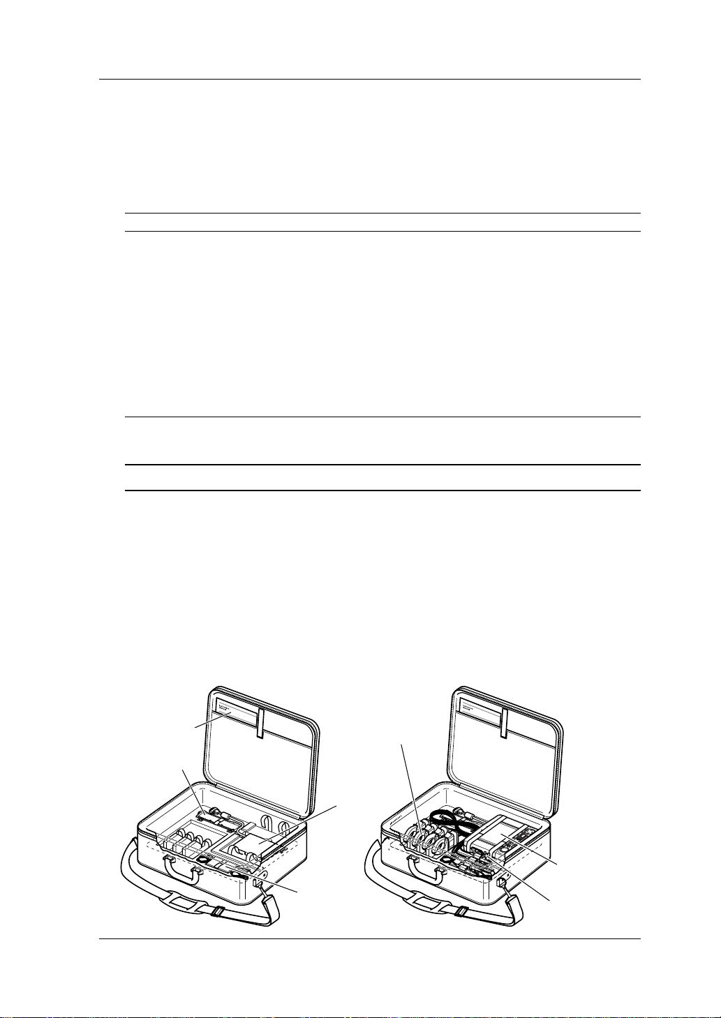
● Housing CW140 Main Unit and Accessories
An optional carrying case can accommodate the CW140 main unit with its
current-sensing clamp-on probes and voltage probes connected to the unit.
The case can also house such accessories as an AC adapter, NiMH battery
pack, floppy drive unit, instruction manual, floppy disks, recording paper, and
so on. It therefore comes in handy when transporting a complete kit of tools
necessary for your measurement.
Example of Housing:
Clamp-on probes
Floppy drive unit
CW140 main unit
AC adapter
Voltage probes
IM CW140-E
3
Page 6

Precautions for Safe Use of the Instrument
When operating the instrument, be sure to observe the cautionary notes given below
to ensure correct and safe use of the instrument. If you use the instrument in any
other way than instructed in this manual, the instrument’s protective measures may
be impaired. Yokogawa M&C Corporation is by no means liable for any damage
resulting from use of the instrument in contradiction to these cautionary notes.
The following safety symbols are used in the instrument and this manual.
Danger! Handle with Care.
This symbol indicates that the operator must refer to an explanation in the instruction manual in
order to avoid risk of injury or death of personnel or damage to the instrument.
Direct Current
This symbol indicates DC voltage/current.
Alternating Current
This symbol indicates AC voltage/current.
ON
This symbol indicates On (power).
OFF
This symbol indicates Off (power).
Double Insulation
This symbol indicates double insulation.
WARNING
Indicates a hazard that may result in the loss of life or serious injury of the user unless the
described instruction is abided by.
CAUTION
Indicates a hazard that may result in an injury to the user and/or physical damage to the pr oduct
or other equipment unless the described instruction is abided by.
NOTE
Indicates information that is essential for handling the instrument or should be noted in order to
familiarize yourself with the instrument’s operating procedures and/or functions.
TIP
Indicates information that complements the present topic.
SEE ALSO
Indicates the reference location(s) for further information on the present topic.
4
IM CW140-E
Page 7

Precautions for Safe Use of the Instrument
Strictly observe the following cautionary notes in order to avoid the risk of
injury or death of personnel or damage to the instrument due to such hazards
as electrical shock.
WARNING
● Removal of Case from the Instrument
• Do not remove the case from the instrument or disassemble/modify the instrument itself.
• Some parts of the inside of the instrument contain high-voltage and, therefore, access to the
internal assembly is extremely hazardous. For inspection and/or adjustment of the internal
assembly, contact the vendor from which you purchased the instrument.
● Use of the Instrument in a Gas Atmosphere
Do not operate the instrument in a location where any flammable or explosive gas/vapor is
present. It is extremely hazardous to operate the instrument in such an atmosphere.
● Inspection of Power Source
• Before turning on the instrument, always make sure the voltage of the power source to be
applied matches the instrument’s supply voltage.
• When using alkaline batteries or an NiMH battery pac k, carefully read the cautionary notes on
battery handling later in this manual.
● Use of Clamp-on Current Probes
• When using clamp-on current probes, keep the circuit voltage below 600 V AC in order to
avoid possible short-circuits or accidents resulting in injury or death.
• Avoid using the instrument if it has been e xposed to rain or moisture or if your hands are wet.
• Do not use clamp-on current probes with any non-insulated conductors.
● Measures In Case of Anomalies
If the instrument begins to emit smoke, becomes too hot, or gives off an un usual smell, immediately turn it off and disconnect the power cord from the outlet. Also turn off power to the
object under measurement that is connected to the instrument’s input terminals. Never attempt to use the instrument again. If any such anomalies as noted above occurs, contact the
vendor from which you purchased the instrument. Do not attempt to repair the instrument
yourself, as doing so is extremely dangerous.
● Handling of Power Cords
Do not place any load on the power cord or allow the power cord to come into accidental
contact with any heat source. Hold the plug of the po wer cord, rather than holding and pulling
the cord itself, when disconnecting it from the outlet. If the power cord is damaged, contact
the vendor from which you purchased the instrument. See page 2 for information on the AC
adapter that is necessary when ordering a replacement power cord.
IM CW140-E
5
Page 8

Contents
Introduction ..............................................................................................................1
Examining Items Contained in the Package..........................................................2
Precautions for Safe Use of the Instrument ..........................................................4
Chapter 1. Product Overview ...............................................................................1-1
1.1 Product Overview ........................................................................................ 1-1
Chapter 2. Components, Their Use and Overrange, and Error Indications ..... 2-1
2.1 Front Panel and Connector Block................................................................ 2-1
2.2 Operation and Functions Keys .................................................................... 2-2
2.3 Connecting Input Signals to Be Measured and External Input Terminals ... 2-3
2.4 Overrange and Other Marks Shown during Measurement.......................... 2-6
Chapter 3. Precautions for Safe Measurement...................................................3-1
3.1 Handling Precautions .................................................................................. 3-1
3.2 Installation Procedure.................................................................................. 3-3
3.3 Precautions for Wiring the Circuit under Test .............................................. 3-4
3.4 Diagrams of Basic Wiring ............................................................................ 3-5
3.5 Wiring the Circuit under Test Using External VT/CT.................................... 3-8
3.6 Connecting a Power Supply and Turning It On/Off ...................................... 3-9
3.7 Performing Measurements with Higher Precision ..................................... 3-18
Chapter 4. Basic Operation Flow and Top Menu Screen ...................................4-1
4.1 Basic Operation Flow .................................................................................. 4-1
4.2 Top Menu Screen ........................................................................................ 4-2
Chapter 5. System Settings..................................................................................5-1
5.1 System Settings .......................................................................................... 5-1
5.2 System Reset .............................................................................................. 5-4
Chapter 6. File Handling ....................................................................................... 6-1
6.1 File Handling ............................................................................................... 6-1
6.2 File Name and File Attribute........................................................................ 6-4
6.3 Entering a File Name................................................................................... 6-5
Chapter 7. Common Functions of All Modes .....................................................7-1
7.1 Wiring .......................................................................................................... 7-1
7.2 Checking Wiring .......................................................................................... 7-3
7.3 Ranges and Number of Digits ..................................................................... 7-6
7.4 Sampling Frequencies and Integration Periods......................................... 7-14
7.5 Frequency Measurement and Low-pass Filters ........................................ 7-16
7.6 Averaging Function.................................................................................... 7-18
7.7 Scaling Function (VT/CT) .......................................................................... 7-19
Chapter 8. Instant Measure Mode........................................................................8-1
8.1 Detailed View of Data Items on Instant Measure Mode Screen .................. 8-1
8.2 Working with the Function Keys .................................................................. 8-4
8.3 Expanded View of Data Items on Instant Measure Mode Screen ............... 8-5
6
IM CW140-E
Page 9

Contents
8.4 Logging in Instant Measure Mode ............................................................... 8-7
8.5 Setup Data Items of Instant Measure Mode.............................................. 8-10
8.6 Computational Expressions....................................................................... 8-15
Chapter 9. Electric Energy Measure Mode .........................................................9-1
9.1 Data Items on Electric Energy Measure Mode Screen ............................... 9-1
9.2 Working with the Function Keys .................................................................. 9-3
9.3 Integration in Electric Energy Measure Mode ............................................. 9-4
9.4 Setup Data Items of Electric Energy Measure Mode .................................. 9-7
Chapter 10. Key .............................................................................................10-1
10.1 Simple Electric Energy Measurement with Key .................................. 10-1
Chapter 11 Demand Measure Mode .................................................................11-1
11.1 About Demand .......................................................................................... 11-1
11.2 Data Items Shown on Demand Measure Mode Screen ............................ 11-2
11.3 Working with the Function Keys ................................................................ 11-4
11.4 Demand Measurement in Demand Measure Mode .................................. 11-5
11.5 Setup Data Items of Demand Measure Mode ........................................... 11-8
Chapter 12. Harmonics Measure Mode ............................................................. 12-1
12.1 Showing Tables in Harmonics Measure Mode .......................................... 12-1
12.2 Showing Graphs in Harmonics Measure Mode......................................... 12-3
12.3 Working with the Function Keys ................................................................ 12-5
12.4 Logging in Harmonics Measure Mode ...................................................... 12-6
12.5 Setup Data Items of Harmonics Measure Mode ....................................... 12-9
12.6 Computational Expressions..................................................................... 12-15
Chapter 13. File Functions .................................................................................13-1
13.1 Saving, Loading and Printing with File Functions...................................... 13-1
Chapter 14. External I/O Functions ...................................................................14-1
14.1 Optional D/A Output .................................................................................. 14-1
14.2 External Control Input ............................................................................... 14-8
14.3 Event Input ................................................................................................ 14-9
Chapter 15. RS-232C Communication Function ..............................................15-1
15.1 RS-232C Interface Specifications ............................................................. 15-1
15.2 Connecting CW140 through RS-232C Interface ....................................... 15-2
15.3 Handshake Methods ................................................................................. 15-4
15.4 Matching the Data Format......................................................................... 15-7
Chapter 16. In the Event of a Power Failure .....................................................16-1
16.1 In the Event of a Power Failure ................................................................. 16-1
Chapter 17. Auxiliary Functions ........................................................................17-1
17.1 Auxiliary Functions .................................................................................... 17-1
17.2 Floppy Disk Drive (Optional)...................................................................... 17-7
17.3 Printer (Optional) ....................................................................................... 17-8
Chapter 18. Troubleshooting .............................................................................18-1
18.1 Corrective Action in Case of Failure .......................................................... 18-1
18.2 Messages and Corrective Measures......................................................... 18-2
1
2
3
4
5
6
7
8
9
10
11
12
13
14
15
16
17
18
19
App
Index
IM CW140-E
7
Page 10

Contents
Chapter 19. Specifications .................................................................................19-1
19.1 Specifications ............................................................................................ 19-1
19.2 Specifications of Current Clamps ............................................................ 19-15
Appendix.........................................................................................................App1-1
Appendix 1 Block Diagram of CW140 Main Unit............................................. App1-1
Appendix 2. Communication Commands.......................................................... App2-1
Appendix 3. Explanation of Data Item to be Saved/Printed .............................App3-1
Appendix 4. Terminology .................................................................................. App4-1
Appendix 5. Explanation of Reactive Power Method........................................App5-1
Appendix 6. Settings Check Sheet................................................................... App6-1
Index............................................................................................................... Index-1
8
IM CW140-E
Page 11

Chapter 1. Product Overview
1.1 Product Overview
The CW140 clamp-on power meter is basically designed for measuring rootmean-square voltage and current rms values and thereby electric energy. With its
computing capabilities, the CW140 can measure and analyze a wide variety of
parameters related to electric power.
This section explains the features of the CW140 and shows a schematic diagram
representing the functions of the CW140. It also explains the screen views (i.e.,
measuring objects) presented by each measurement mode of the CW140.
Features
● Supports a variety of measurement modes and continuous
measurement.
The CW140 has four measurement modes which support continuous
measurement.
• Instant Measure mode (logging)
• Electric Energy Measure mode (integration)
• Demand Measure mode (demand measurement)
• Harmonics Measure mode (logging)
● Efficient Measurement using the Wh Key
This feature simplifies operations required for the Electric Energy Measure mode
most often used.
● Supports a variety of wiring methods.
• Supports single-phase two-wire systems, single-phase three-wire systems,
three-phase three-wire two-current systems, three-phase three-wire threecurrent systems, and three-phase four-wire systems.
• Supports dual-load systems in a single-phase two-wire, single-phase threewire, or three-phase three-wire configuration (except when in the Harmonics
Measure mode).
● Data Management
• Measured values or measurement settings can be stored in internal memory
or on a 3.5-inch floppy disk inserted in an optional floppy drive attached
externally to the CW140.
• Allows simultaneous data saving to internal memory and a floppy disk, or
copying internal memory data to a floppy disk.
• An optional printer connected externally to the CW140 allows you to print
measured values or measurement settings.
● Communication
With an RS-232-C interface, it is possible to transfer data to or receive
measurement settings from a personal computer. The CW140 stores
measurement data in CSV format, facilitating data processing (such as creating
graphs) using commercial spreadsheet software.
● Setting Operations
• Easy-to-operate Display Screen
You can easily change settings by selecting items highlighted on the screen using
Range keys, Cursor key, and function keys.
● Settings Check Sheet
The settings check sheet in Appendix 6 lists required setting items for each
measurement mode. Use this sheet for reference and to improve efficiency when
making settings in the field.
1
Product Overview
IM CW140-E
1-1
Page 12
1.1 Product Overview
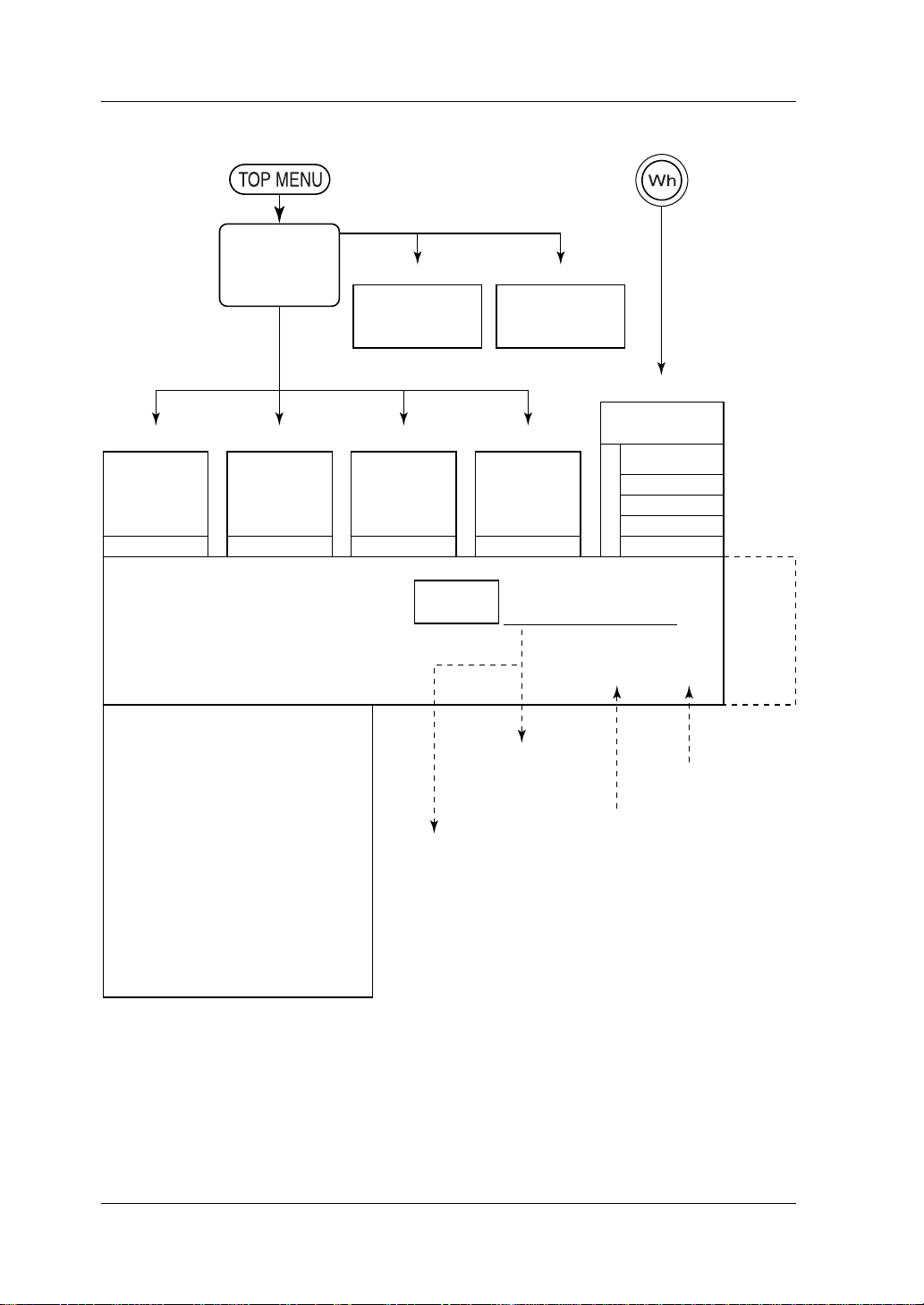
Schematic Function Diagram
key key
TOP MENU
screen
(Chapter 8) (Chapter 9) (Chapter 11) (Chapter 12)
Instant Measure
mode
Logging
Condition setting Condition setting Condition setting Condition setting
Averaging function (Section 7.6)
Scaling function (Section 7.7)
Low-pass filter function (Section 7.5)
Frequency measurement
Wiring check function (Section 7.2)
Power failure handling function (Chapter 16)
Auxiliary functions (Chapter 17)
Clock
Language selection (Japanese, English)
Hold of on-screen readings
NiMH battery recharging
LCD contrast
LCD backlight
Beep (confirmation of key operation)
Key locking
Power-saving mode
System reset
Low battery indicator
Testing backup batteries
Electric Energy
Measure mode
Integration
(Chapter 5) (Chapter 6)
System Setting
mode Screens
1/2 and 2/2
Demand Measure
mode
Demand
Internal
memory
for personal computer or printer
Floppy disk drive unit
(connected externally)
(Section 17.2)
File Handling
Harmonics
Measure mode
(Graph display)
Logging
Storage of data and setup conditions
Reading of setup conditions
RS-232C interface
mode
(Chapter 15)
(Section 17.3)
Event input function
(Chapter 10)
Electric Energy
Measure mode
Last condition
Setting condition 1
Setting condition 2
Setting condition 3
Setting condition 4
Saving set conditions
External trigger function
(Section 14.2)
(Section 14.3)
D/A
output
(Optional)
1-2
IM CW140-E
Page 13

1.1 Product Overview
Demand Measure mode
(Chapter 11)
Indication at the End of Demand
• Maximum demand and its time
• Average of respective demands
• Electric energy integrated from the
start to the end of demand
• Average power factor
• Average load factor
Indication During Demand Interval
• Maximum demand and its time
• Demand of one demand period earlier
• Electric energy integrated since the
start of demand
• Electric energy integrated during the
present demand period
• Power factor
• Load factor
• Remaining time of demand interval
On-screen Information (Data Items) Provided by Each Measurement Mode
In each measurement mode, you can measure and calculate on-screen data
items, as shown below.
Instant Measure mode
(Chapter 8)
Rms voltage value (V)
Rms current value (A)
Active power (W)
Reactive power 1 and 2 (Var)
1: With reactive power meter method
2: Without reactive power meter method
Apparent power (VA)
Power factor
Phase angle (°)
Frequency (Hz)
Three-phase unbalance factor (%) (for three-phase wiring only)
1
Product Overview
Electric Energy Measure mode
(Chapter 9)
Harmonics Measure mode
(Chapter 12)
Table displays
Graph displays
• Voltage/current Rms value, harmonic content, phase angle
• Power
• Voltage/current Rms value, harmonic content, phase angle
• Power
Active power (Wh)
Regenerative power (Wh)
Lagging reactive power (Varh)
Leading reactive power (Varh)
Analysis of 1st- through 13th-order harmonics
Total rms value (All-RMS)
Total harmonic distortion
IEEE (relative to fundamental wave);
CSA (relative to total rms value)
Fundamental wave frequency
Power value, power content, power phase angle
Total power value
Total power factor
Fundamental wave frequency
Power value, power content, power phase angle
IM CW140-E
(The CW140 does not support the Harmonics Measure mode when wired to
2-system load.)
NOTE
The CW140 can show a screen of instantaneous values whether it is in the Electric Energy Measure mode or the Demand Measure mode.
1-3
Page 14

Page 15

Chapter 2. Components, Their Use and Overrange, and Error Indications
)
2.1 Front Panel and Connector Block
Battery charge
LED indicator
(for optional
NiMH battery)
<Side View>
184 (7.24)
AC adapter
jack
Power
switch
N
START
&STOP
<Connector Block>
v
1
v
2
v
3
<Front View>
CLAMP ON POWER METER
FFF
Wh
LIGHT
KEY
LOCK
V
L
L
1
N
INPUT / OUTPUT
23
ESC
AW
L
L
2
3
4
N
N
L1NLNLN L2NL3NL4N
F
4F51
ENTER
TOP MENU
2
Product Overview
N
IM CW140-E
65 (2.56)
206 (8.11)
Unit: mm (approx. inches
2-1
Page 16

2.2 Operation and Functions Keys
Status LED
indicator* for
continuous
measurement
LIGHT
ESC
Name
Function keys
Key Symbol
to
Set data appropriate for information
shown in their respective
corresponding fields along the
Description
Display
bottom edge of the display.
START&STOP
key
Starts/stops logging when the CW140 is in the Instant Measure or Harmonics Measure
mode.
Starts/stops integration when the CW140 is in the Electric Energy Measure mode.
Starts/stops demand when the CW140 is in the Demand Measure mode.
Backlight key
LIGHT
Turns on/off the backlight.
Holding this key down for more than 3 seconds places the CW140 in a key
lock state. To cancel the state, hold this key down again for more than 3
seconds.
Watt-hour key
Allows you to measure electric energy easily without selecting the Electric
Energy Measure mode from the TOP MENU screen.
Escape key
Enter key
Cursor key
V Range key
Cancels such data as setup conditions.
ESC
Confirms such data as setup conditions.
Moves the cursor through on-screen data items so an item can be selected.
Shows/resets the voltage range.
(You can change the setpoint with a function key.)
A Range key
Shows/resets the current range.
(You can change the setpoint with a function key.)
Wiring key
Shows/resets the setting of a wiring method.
(You can change the setting with a function key.) Also see "Checking Wiring."
TOP MENU key
Changes the display to the TOP MENU screen for selecting each
measurement mode.
* Status LED indicator: Remains lit when the CW140 is performing continuous measurement (whether the
meter is in a stand-by state or taking measurements) in each measurement mode.
2-2
IM CW140-E
Page 17

2.3 Connecting Input Signals to Be
Measured and External Input Terminals
● Terminal Assignments
Voltage input terminals
Current (clamp) input terminals
2
Product Overview
v
1
v
N
FDD
Connector for connection with
an external floppy disk drive unit
2
RS-232C
RS-232C connector for
printer/personal computer
Event input terminals: Receive ON/OFF signals from equipment
External control input terminals: Receive START/STOP signals informing
D/A output terminals: Terminals for D/A output
L
CH
1
v
3
LOGIC INPUT START/STOP D/A OUTPUT
Event input terminals
External control (trigger)
input terminals
L
N
L
CH
2
N
L1NLNLN L2NL3NL4N
L
CH
3
D/A output terminals
CH
4
N
(optional)
under test.
of the start and end of logging,
integration or demand measurement.
(not available if the CW140 is not
equipped with a D/A output option).
N
IM CW140-E
2-3
Page 18

2.3 Connecting Input Signal Lines to Be Measured and External Input Terminals
LL1
V INPUT
600V~MAX
TERMINALS 600V ~ MAX
O EAR
TH
CH
CH
CA
FDD
RS-232C
LOGIC NIPUT
ST
AR
T/ST
OP
5.5V MAX
● Connection of Input Signal Lines to Be Measured and External Input
Terminals (Example)
Ring marker
Current clamp
OP
HL H
2
H
C
T/ST
AR
ST
L
LOGIC NIPUT
X
A
.5V M
5
H
1
H
C
L
RS-232C
3
v
FDD
2
v
L
1
v
TH
R
A
E
TO
N
X
A
T.
A
C
V ~ M
600
LS
INA
X
RM
A
E
T
M
V~
600
V INPUT
Voltage probe (red/yellow/blue)
Voltage probe (black)
WARNING
• Thoroughly read Section 3.3, "Precautions for Wiring the Circuit Under Test."
• When wiring the CW140, turn off the circuit under test.
It is extremely dangerous to connect or disconnect measuring lead wires without turning off
the circuit under test.
• Be extremely careful not to connect any voltage-mode cir cuit to the current input terminals or
any current-mode circuit to the voltage input terminals. Miswiring can result in not only damage to the circuit or equipment under test but also an injury to personnel.
• The CW140 can be connect to a maximum of four voltage input probes or four current-sensing
clamps. Do not connect any probe or clamp that is not necessary for measurement.
• Do not use any other probes or current-sensing clamps than those supplied with the CW140.
• Before connecting a current-sensing clamp to the CW140, make sure the H and L polarities are
correctly identified.
● Differentiating among Voltage Input Probes and among Current-
sensing Clamps
• Voltage Input Probes
Probe for Input terminal N: Black (one)
Probes for Input terminals V1 to V3: Three different colors: Red, Yellow and Blue.
• Current-sensing Clamps
Clamps for Input terminals CH1 to CH4: Differentiated by ring markers of four different
2-4
colors
IM CW140-E
Page 19

2.3 Connecting Input Signal Lines to Be Measured and External Input Terminals
● Use of Ring Markers (Standard Accessories)
Attach ring markers of the same color to both the terminal connection side
and alligator clip side of a voltage input probe or to both the terminal
connection side and clamping side of a current-sensing clamp. This enables
you to differentiate between the input signal lines.
CAUTION
Be careful not to damage a probe when attaching ring markers.
● Connection of External I/O Terminals
Signal wire
Tool such as a flat-tip screwdriver
● Connection Procedure
Insert the signal wire into the hole while pressing the rectangular area at the
bottom of the external I/O terminal using such a tool as a flat-tip screwdriver.
Removing the screwdriver from the terminal fixes the signal wire in place.
2
Product Overview
CAUTION
• Do not apply voltages outside the allowable input voltage range (-0.5 to 5.5 V), otherwise the
input circuit may be damaged.
• When wiring the CW140, be careful not to mistake an input terminal for an output terminal.
● Applicable Signal Wires
Standard wire: φ1.0 single-core wire (AWG18) or 0.75 mm
Adaptable wire: φ0.4 to 1.0 single-core wire (AWG26 to 18) or 0.35 to 0.75
mm2 stranded wire (AWG22 to 20) with a minimum strand
diameter of 0.18 mm; typical length of stripping = 10 mm
● Applied Terminals
LOGIC INPUT: Event input terminals (receive ON/OFF signals from
equipment under test)
START/STOP: Terminals for inputting signals informing the start and end of
logging, integration or demand measurement.
D/A OUTPUT: Terminals for D/A conversion output (optional)
IM CW140-E
2
stranded wire
2-5
Page 20
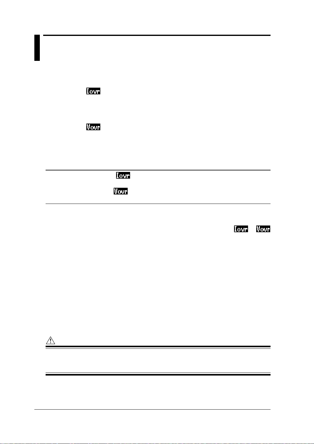
2.4 Overrange and Other Marks Shown
during Measurement
● Overrange Indications during Measurement
: Conditions for current overrange indication
This mark appears if the sampled value exceeds 300% of the rated
current range or if the rms value of the measured current exceeds
110% of the rated range. If a fixed range is used, step up the range.
: Conditions for voltage overrange indication
This mark appears if the sampled value exceeds 300% of the rated
voltage range or if the rms value of the measured voltage exceeds
110% of the rated range. If a fixed range is used, step up the range.
TIP
• The current overrange mark appears if an input signal to one of the terminals CH1 to CH4
satisfies the conditions noted above.
• The voltage overrange mark appears if an input signal to one of the terminals V1 to V3 satisfies
the conditions noted above.
Indication of Overrange Marks When Auto-ranging Is Used
The CW140 steps up or down the range, as discussed in Section 7.3,
"Ranges and Number of Digits." Then, the CW140 shows the or
mark if the conditions noted above become true under the maximum range.
Indication of OR Symbol
The CW140 shows the OR symbol, instead of a usual four-digit value, if the
result of measurement (calculation) satisfies the conditions noted above.
(If a fixed range is used, step up the range.)
Indication of OR Symbol When Auto-ranging Is Used
The CW140 steps up or down the range, as discussed in Section 7.3,
"Ranges and Number of Digits." Then, the CW140 shows the OR
symbol if the conditions noted above become true under the maximum
range.
WARNING
The CW140 shows an overrange mark under the maximum range only if the input level exceeds
the maximum allowable input level. Do not appl y an y input level higher than the maxim um allowable input level.
2-6
IM CW140-E
Page 21

2.4 Overrange and Other Marks Shown during Measurement
CAUTION
When measuring an input signal level exceeding the rated range, use a voltage transformer (VT)
or a current transformer (CT) - scaling function. When using a VT or CT, thoroughl y read Section
3.5, "Wiring the Circuit under Test Using External VT/CT."
● Frequency-related Overrange Indications
Normal measurement: The measurement range is from 45 Hz to 1 kHz.
The display shows "----" if the input signal is below 40 Hz or above 1.2 kHz.
Three-phase unbalance factor measurement:
The measurement range is from 45 to 440 Hz.
The display shows "----" if the input signal is below 40 Hz or above 440 Hz.
Harmonics measurement: The measurement range is from 45 to 65 Hz.
The display shows "----" if the input signal is below 40 Hz or above 70 Hz.
● Indications When the Measured Value Is Too Small
If either a voltage or current input level is below 0.4% of the rated range, the
CW140 gives the readings noted below. If a fixed range is used, step down
the range.
Reactive power 2 and apparent power: Read zero (0).
Power factor and phase angle: Read as "----".
2
Product Overview
If the level of active power or reactive power is below 0.7% of the rating, the
reading is displayed as shown below.
Active power or reactive power: Read zero (0). The integration stops.
In harmonics measurement, the display reads as shown below if the input
level of a frequency-measuring device is below 10% of the rated range.
All measurement data items: Read as "----".
If the voltage, current or power harmonic content in harmonics measurement
is below 0.1%, the phase angle of a harmonic component of that order reads
as "----".
TIP
Even if the instantaneous value overrange occurs and the OR symbol appears in the electric energy
measure mode, the integration processing continues. In this case, the level of accuracy of the on-screen
integrated value may become inaccurate (about two times) that of the rated accuracy.
NOTE
If continuous measurement (logging, integration, or demand) is performed when in AUTO range,
the range will be fixed to the value when the START&STOP key is pressed.
IM CW140-E
2-7
Page 22
2.4 Overrange and Other Marks Shown during Measurement
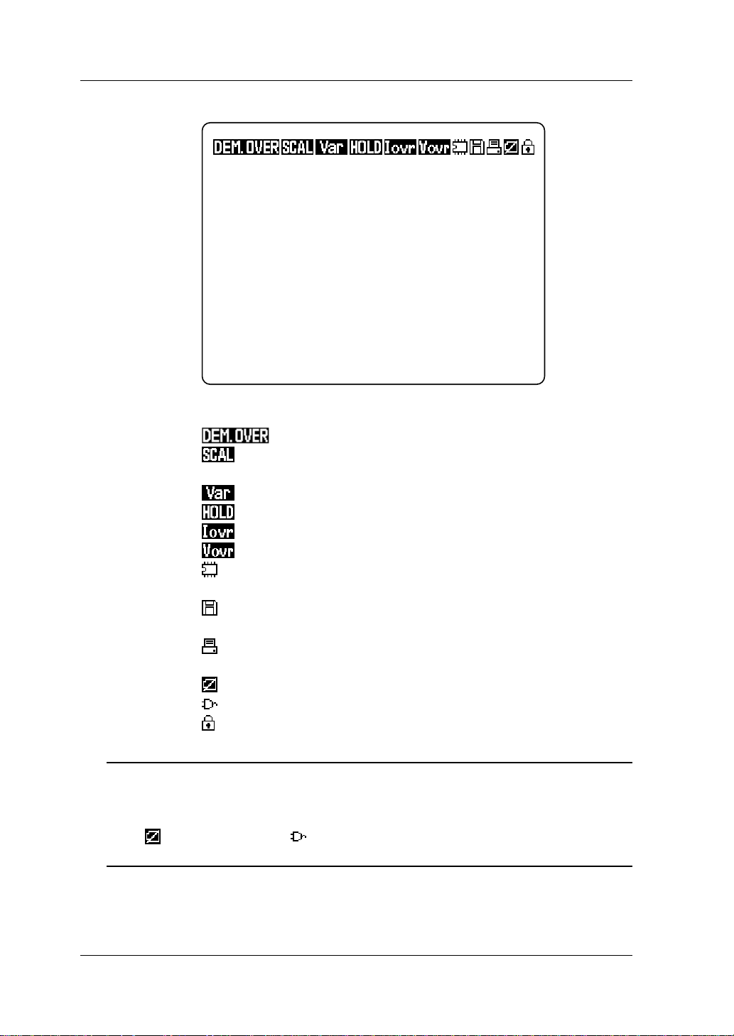
● Other Marks
Screen View
: Appears if the demand exceeds the reference power level.
: Denotes the scaling function.
Appears if either the VT or CT ratio is set at a value other than 1.
: Appears when the reactive power method is used.
: Appears when display hold is enabled.
: Appears when a current overrange occurs.
: Appears when a voltage overrange occurs.
: Appears when the CW140 is configured so that data is stored in
internal memory.
: Appears when the CW140 is configured so that data is stored
on a floppy disk.
: Appears when the CW140 is configured so that data is output to
a printer.
: Appears when the battery becomes low (low-battery mark).
: Appears when an AC adapter is used.
: Appears when the CW140 is in a key lock state.
TIP
• The Floppy Disk mark is only effective if an optional external floppy disk drive is used.
• The Printer mark is only effective if an optional external printer is used.
• The Low-Battery mark appears if either an optional NiMH battery pack or alkaline batteries are used.
• The (Low-Battery mark) and (AC Adapter mark) indications share the same position of view
on the display.
2-8
IM CW140-E
Page 23

Chapter 3. Precautions for Safe Measurement
3.1 Handling Precautions
If you are a first-time user, be sure to read "Precautions for Safe Use of the
Instrument" on pages 4 and 5.
● Do not place any load on the instrument.
Do not place any other equipment of a vessel filled with water on the
instrument. Otherwise, the instrument may become defective.
● Moving the instrument
Before moving the instrument, make sure the power cord and all other cables
are disconnected. When moving the instrument, hold it with both hands.
● Input Terminals
Do not bring any electrified substance close to the signal terminals.
Otherwise, the internal circuitry may be destroyed. Do not apply any
mechanical shock to the signal terminals. Otherwise, such impact may be
transformed into electrical noise and input to the instrument.
3
Precautions for Safe Measurement
● Protection of Case and Operation Panel
Do not spray any volatile chemical on the case or operation panel. Do not
leave any rubber or vinyl product in contact with the instrument for a
prolonged period. Otherwise, the instrument may be discolored or deformed.
● Cleaning
When cleaning the case and/or operation panel, disconnect the power cord
from the outlet. Then, wipe the surfaces of the case and/or operation panel
with a soft clean cloth. Do not use chemicals such as benzine or paint thinner.
Otherwise, the instrument may be discolored or deformed.
● Display Screen
When the instrument is shipped from the factory, the display screen is
covered with a protective film. Remove the film before you begin using the
instrument.
The LCD backlight lasts a approximately 10,000 hours when kept turned on at
room temperature. If it is used longer than that period, the brightness may
drastically decrease. If this occurs, the backlight needs to be replaced.
Contact the vendor from which you purchased the instrument.
IM CW140-E
3-1
Page 24

3.1 Handling Precautions
● After Use
After use, disconnect the power cord from the outlet.
● Long Absence of Use
If the instrument will not be used for a prolonged period, remove the batteries
(AA-size alkaline batteries or NiMH battery pack) from the instrument.
Precautions for Use of the Clamp
CAUTION
• The clamping CT (current transformer) is precision assembled to ensure high performance.
When using the clamp, do not apply any intense mechanical shock, vibration or force to the
clamping CT.
• If dust or any other foreign matter gets in the clamping CT, do not shut the clamping cores
tight. First remove the dust and then make sure the clamping cores on both sides close
smoothly.
3-2
IM CW140-E
Page 25

3.2 Installation Procedure
Install the instrument in a location that satisfies the following conditions.
● Ambient Temperature and Humidity
• Ambient temperature: 5°C to 40°C
• Ambient humidity: 35 to 80% RH (no condensation)
● Operating altitude
2000m max. above sea level
● Level Location
Do not install the instrument in an unstable or inclined location. Otherwise,
this may result in the failure to obtain precision measurements.
● Do not install the instrument in a location that is:
• exposed to direct sunlight or close to a heat source;
• close to such a noise source as high-voltage equipment or a motive power
supply;
• exposed to a relatively large amount of lampblack, steam, dust or
corrosive gas;
• exposed to frequent mechanical vibration;
• close to a source of strong electromagnetic fields; or
• unstable.
3
Precautions for Safe Measurement
IM CW140-E
3-3
Page 26
3.3 Precautions for Wiring the Circuit
under Test
WARNING
• When wiring the instrument or the instrument is turned off, turn off the circuit under test.
It is extremely dangerous to connect or disconnect measuring lead wires without turning off
the circuit under test.
• Be extremely careful not to connect any volta ge-mode circuit to the current input terminals or
any current-mode circuit to the voltage input terminals. Miswiring can result in not only damage to the circuit or equipment under test but also an injury to personnel.
• Do not apply any input level higher than the following to the v olta ge or current input terminals.
• Maximum allowable input (continuous)
Voltage input: 600 Vrms
Current input: 250 Arms Clamp A (96030)
625 Arms Clamp C (96031)
*700 Arms Clamp B (96032)
* Refer to Section 19.2, “Specifications of Current Clamps” for details.
In addition to the maximum allowable input, the rated input levels are specified as shown
below.
Voltage ratings: 150, 300 and 600 V
Current ratings: 20, 50, 100 and 200 A Clamp A (96030)
50, 100, 200 and 500 A Clamp C (96031)
200, 500 and 1000 A Clamp B (96032)
• If using an external VT (voltage transformer) or CT (current transformer), make sure the transformer can adequately withstand the voltage being measured.
• Be careful not to allow the secondary stage of the CT to become open-circuited while the CT is
being electrified. Otherwise, a high-voltage may develop on the secondary stage, causing
extreme danger.
• The maximum allowable input voltage range of the external input terminals (external control
input and event input terminals) is specified as –0.5 to 5.5 V.
Do not apply voltages exceeding this range, otherwise the input circuitry may be damaged.
(When wiring the input terminals, be careful not confuse them with the optional D/A output
terminals.)
• Do not use any probes or clamps other than those voltage input probes or dedicated clamps
supplied together with the CW140.
• Do not use a clamp with any non-insulated conductors.
TIP
After wiring the CW140, it is necessary to perform setting/operation for the wiring method using the
WIRING key.
SEE ALSO
Section 7.1, "Wiring," for details on how to set the wiring method.
3-4
IM CW140-E
Page 27
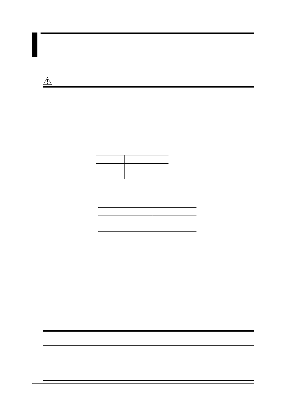
3.4 Diagrams of Basic Wiring
This section explains the methods of basic wiring using illustrations.
Current-sensing clamp
(1) 1
φφ
φ2W
φφ
S
1
O
U
N
R
C
E
L
O
A
D
3
Precautions for Safe Measurement
(2) 1
(3) 3
Voltage input terminals Current input terminals
φφ
φ3W
φφ
Voltage input terminals Current input terminals
φφ
φ3W2i
φφ
S
O
U
R
C
E
S
O
U
R
C
E
NV1 CH1
1
N
2
NV1 CH1
R
1
S
2
T
3
I1
V2 CH2
I2
I1
On-screen symbol
L
O
A
D
On-screen symbol
L
O
A
D
Voltage input terminals Current input terminals
TIP
In the case of a current-sensing clamp, the symbol of a current input terminal shown on the CW140 main
unit differs from that shown on the display, as indicated in the figures above.
IM CW140-E
NV1 CH1
V3 CH3
I1
I3
On-screen symbol
3-5
Page 28
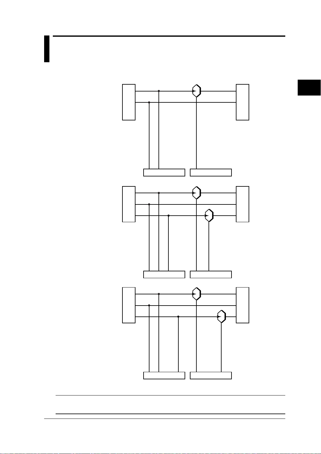
3.4 Diagrams of Basic Wiring
(4) 3
(5) 3
φφ
φ3W3i
φφ
Voltage input terminals Current input terminals
φφ
φ4W
φφ
R
S
1
O
U
S
2
R
C
T
3
E
NV1 CH1
R
S
1
O
S
2
U
R
T
3
C
N
E
N
V3 CH3
CH2
I3
I2
I1
L
O
A
D
On-screen symbol
L
O
A
D
Voltage input terminals Current input terminals
V2 V3 CH3
NV1 CH1
I1 I3
CH2
I2
On-screen symbol
When connecting the current-sensing clamp, make sure the following polarities and clamp
position are correctly identified.
1 When connecting to
the CW140 main unit:
H and L polarities
Conductor
cable
Power supply side
(SOURCE)
2 The clamp should be
positioned in the
direction from the
power source side to
the load side, as
indicated by the
arrow.
Load side
(LOAD)
Connector on the main unit
WARNING
In addition to using the checking wiring function, be sure to verify the actual wiring connections.
3-6
IM CW140-E
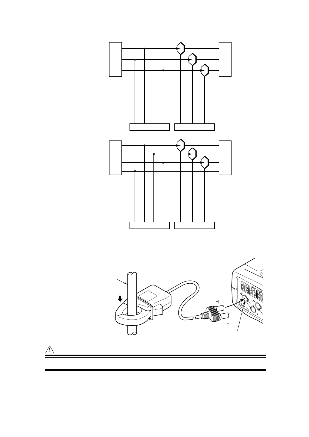
Page 29
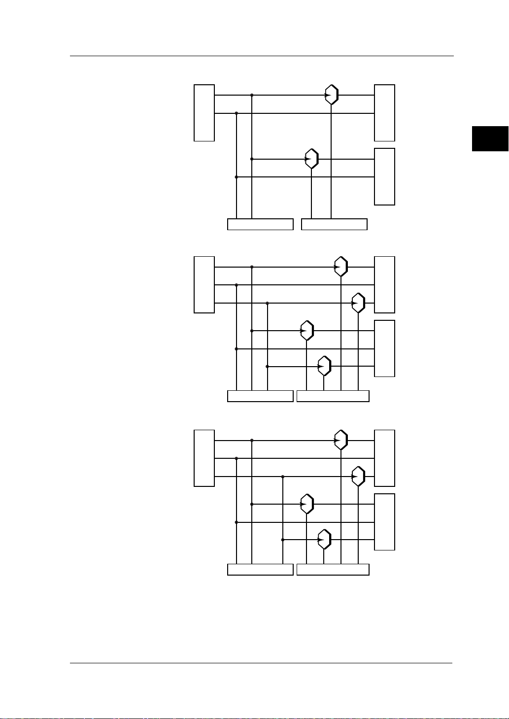
- 2-system load -
φφ
(6) 1
φ2W
φφ
××
×2
××
3.4 Diagrams of Basic Wiring
S
1
O
U
N
R
C
E
L
O
A
D
2
3
L
O
A
D
1
Precautions for Safe Measurement
(7) 1
(8) 3
Voltage input terminals
φφ
××
φ3W
×2
φφ
××
Voltage input terminals
φφ
××
φ3W
×2
φφ
××
Current input terminals
On-screen symbol
L
O
A
D
2
L
O
A
D
1
Current input terminals
CH4
On-screen symbol
I2-2
L
O
A
D
2
L
O
A
D
1
CH1
I1
CH2
I1-2
I1
CH3
CH2
I1-2
I2-1
NV1 CH1
S
1
O
U
N
R
C
2
E
NV1
V2
R
S
1
O
S
U
2
R
C
T
3
E
IM CW140-E
Voltage input terminals
NV1
V3
CH1
I1
CH2
I3-1
CH3
I1-2
Current input terminals
CH4
On-screen symbol
I3-2
3-7
Page 30

3.5 Wiring the Circuit under Test Using
External VT/CT
WARNING
• When using an external CT, be careful not to allow the secondary stage of the CT to become
open-circuited while the primary stage is being electrified. Otherwise, a high voltage may
develop on the secondary stage, causing extreme danger.
• The current under test flows through the bold lines shown in the figure below . For these lines,
use wire that has an adequate margin of current-carrying capacity.
If the maximum voltage or current level being measured exceeds the
maximum measurement range of the CW140, use an external VT and/or CT.
This strategy enables the measurement of voltage or current levels above the
maximum range.
If the maximum voltage level exceeds 600 V, attach an external VT. Then,
connect the secondary stage of the VT to the voltage input terminals.
If the maximum current level exceeds the following value, attach an
external CT. Then, connect the secondary stage of the CT to the currentsensing clamp.
200 A, when clamp A (20, 50, 100 and 200 A) is used
500 A, when clamp C (50, 100, 200 and 500 A) is used
1000 A, when clamp B (200, 500 and 1000 A) is used
Example of 1φ2W
S
O
1
U
R
N
C
E
Voltage
transfomer
TIP
• The CW140 can show the primarystage value even if the scaling function is applied using VT/CT.
SEE ALSO
Section 7.7, "Scaling Function," for details on how to use VT/CT.
• The lowest current range of the CW140 main unit itself is 20 A on full scale and the accuracy also
depends on this value. Note therefore that if a CT is used and its secondary output is too small when
compared with 20 A, then the error ratio will become higher.
V
VT
v
V1Voltage input terminals Current input terminalsN CH1
L
艎
L
O
A
D
CT
Current
transfomer
3-8
IM CW140-E
Page 31

3.6 Connecting a Power Supply and
Turning It On/Off
The CW140 can be operated with the following three types of power supply.
• Six AA-size alkaline batteries
• AC power supply through an AC adapter (standard accessory)
Part number: 788011 Yokogawa’s AC adapter
• Rechargeable NiMH battery pack (optional accessory)
part number: 94004
Using AA-size Alkaline Batteries
Alkaline Batteries: “AA”-size [LR6], 1.5V
● Handling Precautions
Observe the following cautionary notes when handling alkaline batteries.
WARNING
• Install the alkaline batteries with the positive and negative polarities correctly positioned, otherwise the battery fluid may leak or the batteries may explode.
• Do not disassemble the batteries, heat them, or throw them into a fire.
• Do not short-circuit the batteries.
• Do not attempt to recharge the batteries.
• Do not solder the batteries.
• When replacing the batteries, replace all of the six units at one time with new ones from the
same manufacturer. (Do not use manganese batteries as replacements.)
• If the instrument will not be used for a prolonged period, remove the batteries.
3
Precautions for Safe Measurement
IM CW140-E
● Operating Hours of Alkaline Batteries
The operating hours of an alkaline battery vary depending on its operating
environment and conditions. Refer to the following information.
Operating Hours: Approx. 3 hours
Operating Conditions: The LCD backlight is turned off and no floppy drive is connected.
3-9
Page 32

3.6 Connecting a Power Supply and Turning It On/Off
NOTE
• If the voltage of an alkaline battery falls below a given level, the mark appears in the upperright corner of the display (low-battery state). If you continue to operate the CW140 in this
state, the meter automatically turns off.
• If the low-battery mark appears during measurement, change the power suppl y to an AC sour ce.
Wait until the CW140 finishes or aborts measurement and therefore is ready for shutdown,
before replacing the batteries with new ones.
● Procedure for Replacing Alkaline Batteries
Follow the steps below to replace alkaline batteries.
1. Make sure the power switch on the CW140 is turned off and no AC
adapter is connected.
2. Remove the battery holder on the back of the CW140.
3. Place six new alkaline batteries in the battery holder.
SEE ALSO
The figure given below.
House the batteries with the positive and negative polarities of each battery positioned correctly.
4. Hold the battery holder so that the battery connector on the CW140
correctly mates with the battery holder connector. Then, slide the battery
holder into the slot on the CW140 with the holder's two guides engaged in
the groove of the slot. Finally, make sure both connectors are precisely
mated with each other.
5. Push down the lock switch on one side of the CW140 to fix the battery
holder in place.
(The label changes to "∆FREE".)
3-10
IM CW140-E
Page 33

3.6 Connecting a Power Supply and Turning It On/Off
Using the AC Adapter (Standard Accessory)
● Handling Precautions
There is a danger of electrical shock or damage to the meter. Observe the
following cautionary notes when handling the AC adapter.
WARNING
• Only use the manufacturer-supplied dedicated power cord.
• Before connecting the power cord, make sure the power-source voltage matches the supply
voltage rating of the AC adapter.
• Before connecting the power cord, also make sure the power switch on the CW140 is turned
off.
• If the CW140 is not to be used for a prolonged period, disconnect the power cord from the
outlet.
• Do not use any other AC adapter than the one (part number: 788011) dedicated to the CW140.
• Do not place any load on the power cord or allow the power cord to come into accidental
contact with any heat source.
• Be sure to hold the plug of the power cord, rather than holding and pulling the cord itself, when
disconnecting it from the outlet.
3
Precautions for Safe Measurement
IM CW140-E
3-11
Page 34

3.6 Connecting a Power Supply and Turning It On/Off
● Procedure for Connecting the AC Adapter
Follow the steps below to connect the AC adapter.
1. Make sure the power switch on the CW140 is turned off.
2. Attach the clamp filter supplied together with the AC adapter to the outputside cable of the power cord.
SEE ALSO
The figure given below.
Approx.
10 cm
part number: A1193MN
AC-input side
(for connection to the AC power outlet)
Side for connection
to the CW140
clamp filter
3. Connect the AC adapter plug to the AC adapter jack of the CW140.
4. Connect the plug of the power cord supplied together with the AC adapter
to the power supply connector of the AC adapter.
5. Connect the other end of the power cord to a power outlet that satisfies the
power ratings (requirements) shown below.
Power Ratings of AC Adapter
Supply voltage rating 100 to 240 V AC
Allowable supply voltage range 90 to 264 V AC
Power supply frequency rating 50/60 Hz
Allowable power supply frequency range 48 to 62 Hz
Maximum power consumption 70 to 90 VA
Output voltage rating of AC adapter 12 V DC
Maximum output current rating of AC adapter 2.6 A
3-12
IM CW140-E
Page 35

3.6 Connecting a Power Supply and Turning It On/Off
Using a NiMH (Nickel-Hydrogen) Battery Pack (Optional Accessory)
● Handling Precautions
Observe the following cautionary notes when handling the dedicated NiMH
battery pack.
Specifications
Voltage : 7.2V
Capacity : 2100mAh
Number of times can be changed (life cycle) :
Approx. 300times (varies with the operating environment)
WARNING
• Since the electrolyte solution inside the battery pack is alkaline, it may damage any clothing or
skin it comes into contact with due to a leakage from or rapture in the battery pack. In particular, if the solution enters an eye it may cause loss of eyesight. Therefore in such a case, thoroughly wash the affected eye with clean water immediately. Then, receive treatment from a
doctor right away.
• When replacing the NiMH battery pack, be sure to turn off the power switch of the CW140 meter
and remove the power cord from the outlet to avoid possible danger, such as a short in the
electric circuit or electrical shock.
• Do not use any other battery pack than the manufacturer-supplied NiMH battery pack (part
number: 94004).
• Do not leave the NiMH battery pack in a place that is subject to strong direct sunlight, inside a
vehicle under a blazing sun, or near a fire. Doing so may cause a solution leakage, or deterioration in the performance and/or the service life of the battery pack.
• Do not disassemble or modify the battery pack. Doing so may damage the protective properties of the battery pack and cause it to heat up and rapture.
• Do not short the battery electrodes, as this may cause burns due to the battery pack heating
up.
• Do not place the battery pack into a fire or apply heat to it. Doing so is dangerous, as there is
a risk that it will rupture, scattering electrolyte solution.
• Do not apply excessive shock to the battery pack, for example, by throwing it. Doing so may
cause solution leakage, battery pack heating, or a rapture.
• Refrain from using a defective battery pack, such as one with leaking solution, a deformation,
discoloring or any other abnormality.
• Avoid any metal coming into contact with the battery pack when carrying it, as there is the
danger of a short occurring.
• Do not immerse the battery pack in water or make it wet, as this may cause it to heat up or rust,
as well as lead to a loss of functions.
• If the battery pack is not used for a prolonged period, remove it from the CW140 main unit and
store it in the following environment:
Storage period of 1 year or less: Temperature of –20°C to 35°C
(in a place with low humidity)
Storage period of 3 months or less: Temperature of –20°C to 45°C
(in a place with low humidity)
3
Precautions for Safe Measurement
IM CW140-E
3-13
Page 36

3.6 Connecting a Power Supply and Turning It On/Off
● Procedure for Installing the NiMH Battery Pack
Follow the steps below to install the dedicated NiMH battery pack.
1. Make sure the power switch on the CW140 is turned off.
2. If the AC adapter is in use, disconnect the power cord of the AC adapter
from the outlet.
3. If alkaline batteries are in use, remove them from the battery holder and
install the NiMH battery pack.
4. Hold the battery holder so that the battery connector on the CW140
correctly mates with the battery holder connector. Then, slide the battery
holder into the slot on the CW140 with the holder's two guides engaged in
the groove of the slot. Finally, make sure both connectors are precisely
mated with each other.
5. Push down the lock switch on one side of the CW140 to fix the battery
holder in place.
(The label changes to "∆FREE".)
SEE ALSO
The figure given below.
3-14
IM CW140-E
Page 37

3.6 Connecting a Power Supply and Turning It On/Off
● Recharging the NiMH Battery Pack
The optional dedicated NiMH battery pack is not fully charged when shipped
from the factory. Before use, recharge the battery pack to its full level. When
recharging it, use the AC adapter.
WARNING
• When recharging the NiMH battery pack, be sure to do so through the CW140 main unit.
• When recharging the NiMH battery pack, keep the ambient temperature within the range from
10°C to 35°C. Recharging the battery pack outside this range may result in an insufficient
amount of charge, solution leakage, or battery heating.
● Procedure for Recharging the NiMH Battery Pack
Follow the steps below to recharge the NiMH battery pack.
1. With the battery pack installed as instructed earlier, connect an AC
adapter to the CW140.
2. At this point, keep the power switch on the CW140 turned off. The LED
indicator beside the AC adapter jack comes on, indicating that the battery
pack is being recharged. When recharging is complete, the LED indicator
flashes rapidly.
3
Precautions for Safe Measurement
NOTE
If the power switch on the CW140 is turned on, the NiMH battery pack is not recharged. In that
case, the CW140 is powered from the AC adapter.
IM CW140-E
3-15
Page 38

3.6 Connecting a Power Supply and Turning It On/Off
TIP
• The CW140 is in a wait-for-recharge state when the LED indicator is flashing slowly (lit for approximately one second when on). The meter falls into this state when:
• the ambient temperature is outside the range from 10°C to 35°C;
• the battery performance is remarkably low due to over-discharge or for other reasons; or
• the NiMH battery pack is not installed yet.
• The LED indicator flashes rapidly if:
• the battery temperature rises above 55°C, or
• the ambient temperature changes drastically,
indicating that the battery pack has been recharged to its full level.
However in practice, the battery pack may not have been recharged completely for some reason.
● Indication that Recharge Is Required
NOTE
• If the voltage of the NiMH battery pack falls below a given level, the mark appears in the
upper-right corner of the display (low-battery state). If you continue to operate the CW140 in
this state, the meter automatically turns off.
• If the low-battery mark appears during measurement, change the power suppl y to an AC sour ce.
Wait until the CW140 finishes or aborts measurement and therefore is ready for shutdown,
before replacing the batteries with new ones.
● Operating Hours of NiMH Battery Pack
The operating hours of an NiMH battery pack vary depending on its operating
environment and conditions. Refer to the following table.
Operating Hours: Approx. 7 hours
Operating Conditions: The LCD backlight is turned off and no floppy drive is connected.
● Service Life of NiMH Battery Pack
The NiMH battery pack can be recharged approximately 300 times, though
the frequency depends on its operating environment. The life of the battery
pack is over if the low-battery mark appears soon after the battery pack has
been fully recharged. Replace the battery pack with a new one.
3-16
IM CW140-E
Page 39

3.6 Connecting a Power Supply and Turning It On/Off
Startup Screen
When you turn on the power switch on the CW140 main unit, the display successively presents
the screens described in paragraphs (1) and (2) below.
(1) Model Name Screen
The CW140 first shows such a
screen as illustrated on the right,
then performs a self-test.
(2) Message Screen
1Indication of the model name
and version
2 Result of SRAM test
3 Result of backup SRAM test
4 Result of EEPROM
5Indication of function code
6 Result of RTC (real-time clock)
test
7 Result of floppy disk controller
test
8 Result of checking setup data
9 Result of internal flash memory
disk test
CW140 Ver.0.00
SRAM Check Ok
Battery Backup SRAM Check Ok
EEPROM OK
Function Code ...00000000
RTC Check Ok
FDC Check Ok
Setting Ok
Flash Disk Ok
3
Precautions for Safe Measurement
1
2
3
4
5
6
7
8
9
NOTE
If an error is found with any of the tests shown on the Message screen discussed in paragraph 2
above, the CW140 shows information about that error.
See Section 18.1, "Corrective Actions in Case of Failure," for more information.
IM CW140-E
3-17
Page 40

3.7 Performing Measurements with Higher
Precision
To perform measurements with higher precision, use the CW140 under the
following environmental conditions.
Ambient temperature: 23 ±5°C
Ambient humidity: 35 to 75% RH (no condensation)
If installing the CW140 in a location where the ambient humidity is 30% or
less, use such equipment as an anti-static mat to prevent electrostatic
discharge.
If you move the CW140 from an area of low temperature and humidity to an
area of high humidity and temperature or if there is a sudden change in the
ambient temperature, condensation may occur in the meter. If this happens,
let the meter stand still for at least one hour to allow it to adapt to the new
ambient temperature and for condensation to dissolve. Then, begin operating
the meter.
● Relationship between Clamp and Conductor
1 When performing a
measurement, hold the
clamp-on probe so that the
conductor cable runs
through the center of the
clamping CT.
2 Ensure that the orientation
of the clamp to the
direction of the conductor
cable (from the power
supply to the load) is
correct, as shown on the
right.
3 Ensure that the clamping
CT is properly closed.
Conductor
cable
Joint section
Clamping CT
Power supply side
(SOURCE)
Load side
(LOAD)
3-18
IM CW140-E
Page 41

Chapter 4. Basic Operation Flow and Top Menu Screen
4.1 Basic Operation Flow
AC adapter
Supply power to CW140
AA alkaline batteries
NiMH battely pack
Turn on power of CW140
Opening message
When you use the CW140 with
the most recently used settings.
Same status as last time
power was turned off
Press the TOP MENU key to
rertrieve the Top Menu.
Selection of mode
Measurement Mode
Instantaneous value measurement
Electric energy measurement
Demand measurement
Harmonics measurement
Press key (SETUP) to make
and modify settings each mode.
<Chapter 11>
TOP MENU
TOP MENU
<Chapter 8>
<Chapter 9>
<Chapter 12>
<Section 3.6>
<Section 4.2>
When you want to
modify settings
Setting Mode
System settings <Chapter 5>
File handling <Chapter 6>
Go to the Top Menu for first-time
use after delivery.
Handy for electric
energy measurement
Settings at end of last measurement
Setting condition 1
Setting condition 2
Setting condition 3
Setting condition 4
<Chapter 10>
4
Basic Operation Flow and Top Menu Screen
IM CW140-E
Calls up wiring settings <Section 7.1>
Calls up voltage range settings <Section 7.3>
Calls up current (ampere) range settings <Section 7.3>
Perform wiring
When you do not want
to check the wiring.
Press to check the wiring. <Section 7.2>
Perfoem measurement
Press key when you want to
perform measurement
continuously
4-1
Page 42

4.2 Top Menu Screen
The Top Menu is used to select measurement and setting modes. Press the
key to retrieve the Top Menu.
● Modes Displayed on Top Menu
Key operation
Measurement Mode See
Instantaneous value measurement Chapter 8
Electric energy measurement Chapter 9
Demand measurement Chapter 11
Harmonics measurement Chapter 12
● Top Menu Display and Selecting Modes
Retrieves the Top Menu.
Using the Cursor key,
select the desired mode.
(It becomes highlighted.)
Setting Mode See
System settings Chapter 5
File handling Chapter 6
TOP MENU
The selected mode screen appears.
TIP
You can also use the key to select the electric energy mode.
4-2
IM CW140-E
Page 43

Chapter 5. System Settings
5.1 System Settings
This section describes system settings, including calculation selection,
auxiliary function settings, and RS-232-C settings. Each setting has been set
to the default value before shipment and should be changed as required.
● Screen Configuration
The System Setting screen consists of 2 pages, pages 1/2 and 2/2.
SEE ALSO
For the contents of each screen and setting details, see Table "System Settings" on pages 5-2 and 5-3.
● Basic Operation for Setting/Modification
Key operation
Retrieves the Top Menu.
Using the Cursor key,
select the system setting.
(It becomes highlighted.)
SYSTEM SET
SYSTEM RESET
Select system setting.
(It becomes highlighted.)
System setting screen
appears.
Using the Cursor key,
select an item to set.
TOP MENU
5
System Setting
ESC
IM CW140-E
Using the function keys,
change the settings on
screen 1/2.
Press the F5 key, to
change the next screen.
Using the function keys,
change the settings on
screen 2/2.
Applies the changes you
made to the settings.
Press the escape key to cancel all
the changes you made.
5-1
Page 44

5.1 System Settings
System Settings 1/2
Screen
Reactive power
method
Frequency
source
Low-pass filter
(Frequency
measurement)
VT ratio
(Ratio of voltage
transformation)
CT ratio
(Ratio of current
transformation)
1/2
Item Items to be selected See also Default
ON (The method is used)
OFF (The method is not used)
To be changed →
Displays the selectable items in
the center of the screen.
ON (Selected)
OFF (Not selected)
Set to a value within 1 to 10,000.
Select the
desired setting.
Section 8.6,
"Computational
Expressions"
Section 7.5,
"Frequency
Measurement
and Low-pass
Filters"
Section 7.5, "Frequency
Measurement and Lowpass Filters"
Section 7.7,
"Scaling Function"
OFF:
The method is
not used
V1
OFF
1
Move to the digit to be changed.
+
Input values.
–
Set to a value within 0.01 to 10,000.
Section 7.7,
"Scaling Function"
1
Move to the digit to be changed.
+
Input values.
–
Clamp selection 20–200 A
Clamp A (20–200 A)
Clamp B (200–1000 A)
Clamp C (50–500 A)
Number of
averaging
cycles
Backlight (LCD)
auto-off when
LIGHT
key is ON
Contrast (LCD) Section 17.1,
Beep Section 17.1,
+ OFF
→
2 → 3 → ... 10 → OFF
→
– OFF
10 → 9 → ... 2 → OFF
ON (Auto-off when no key action is
performed for 10 minutes)
OFF (Not used)
Adjusts LCD's contrast (1 to 8).
+
Input values.
–
ON (Beeps for every key action)
OFF (Not used)
Power-saving
mode (LCD)
ON (Used)
OFF (Not used)
Section 7.6,
"Averaging
Function"
Section 17.1,
"Auxiliary
Functions"
"Auxiliary
Functions"
"Auxiliary
Functions"
Section 17.1,
"Auxiliary
Functions"
5-2
Clamp A
OFF
(Not used)
ON
4
ON
OFF
IM CW140-E
Page 45

System Settings 2/2
5.1 System Settings
Screen
RS-232C settings
2/2
Item Items to be selected See also Default
Connected
instrument
Baud rate
Data length
Parity Section 15.1,
Stop bit
Busy control OFF/OFF
Printer
PC
To be changed →
1200/2400/4800/9600/19200 bps
7
8
None
Odd
Even
1 bit
2 bit
For printer
OFF/OFF
XON/XOFF
CS/RS
Displays the selectable items
in the center of the screen.
For PC
Select to highlight
the desired setting.
OFF/OFF
XON/XOFF
XON/RS
CS/RS
Section 17.3,
"Optional Printer"
Section 15.1,
"RS-232C
Interface
Specifications"
Section 15.1,
"RS-232C Interface
Specifications"
"RS-232C
Interface
Specifications"
Section 15.1,
"RS-232C Interface
Specifications"
Section 15.3,
"Handshaking
Methods"
PC
9600 bps
8
None
1 bit
(No handshaking)
5
System Setting
Date/Time Section 17.1,
Language
IM CW140-E
+
Input values.
–
Applies the changes
Selects the item to be changed.
Year ↔ Month ↔ Day ↔ Time
(CHANGE) Press this key.
English Francais
Deutsch Italiano Español
Use the cursor key to select the language.
Press this key to confirm the selection.
"Auxiliary
Functions"
Section 17.1,
"Auxiliary
Functions"
JST
Japan Standard
Time
English
5-3
Page 46

5.2 System Reset
This section describes how to restore the default settings for all of the system settings (except for
date, time and language).
The language set before the reset can not be changed even if the system reset is executed. (Refer
to “Selecting Language” on page 17-1.)
● Top Menu Operation
Key operation
Retrieves the Top Menu.
Using the Cursor key,
select to highlight the
system settings.
SYSTEM SET
SYSTEM RESET
Select the system reset.
(It becomes highlighted.)
A message requesting confirmation appears.
TOP MENU
● System Reset
System reset confirmation screen
All parameters will be initialized
to default. Proceed?
Enter key: YES ESC key: NO
5-4
Executes system reset.
Press the key to cancel execution of system reset
ESC
and to return to the previous screen.
If system reset has been executed, the following message appears:
System reset executed. All parameters
are initialized to default.
Enter key: OK
Retrieves the Top Menu.
IM CW140-E
Page 47

Chapter 6. File Handling
6.1 File Handling
This section describes how to format memory or a floppy disk, and make modifications to saved files.
● Top Menu Operation
Key operation
TOP MENU
Retrieves the Top Menu.
Using the Cursor key,
select file handling.
(It becomes highlighted.)
The file handling
screen appears.
6
File Handling
Select a desired item.
(It becomes highlighted.)
The respective screen
SEE ALSO
For details on making settings, see Table "File Handling Items".
● File Handling Items
Change file name: Renames a saved file.
Delete file: Deletes a saved file.
FD format: Formats a floppy disk.
Memory format: Formats internal memory.
Data copy: Copies a file in internal memory to a floppy disk.
Program update: Refer to NOTE on page 6-3.
TIP
To use the floppy disk items, an optional floppy disk drive is required.
IM CW140-E
6-1
Page 48

6.1 File Handling
File Handling Items 1/2
Item Description Message
Change file name Select media.
MEMORY
FD
Select media.
Selects a file to rename.
Enter a new name (Refer to Section 6.3).
Delete file Select media.
MEMORY
FD
Select media.
Selects a file to delete.
Cancels selection of a file.
Selects all files on screen.
Selected file
will be deleted.
Selected file will be deleted.
Proceed?
ENTER key: YES
ESC key: NO
Cancels selection of all files.
NEXT screen.
Asterisk (*) is displayed on the left of selected file.
File deleted.
ENTER key: OK
Delete confirmation screen appears.
FD format Format FD.
1.44 MB
1.2 MB
Select capacity type.
Format FD.
(_MB)
ENTER key: YES ESC key: NO
Now formatting. (_MB)
Format complete. (_MB)
ENTER key: OK
Memory format Format internal memory?
Formats memory.
ENTER key: YES ESC key: NO
6-2
Now formatting
Format complete.
ENTER key: OK
IM CW140-E
Page 49

6.1 File Handling
File Handling Items 2/2
Item Description Message
Data copy Selected file will be copied to FD.
SEE ALSO
For more about file names and attributes, see Section 6.2.
Selects a file to copy.
Cancels selection of a file.
Selects all files on screen.
Cancels selection of all files.
Shows more files.
Astersik (*) is displayed on the left of
selected file.
Copy confirmation screen appears.
● File Description
Example :
WTH001.SET
File name
Date: Y ear/Month/Day
Proceed?
ENTER key: YES ESC key: NO
Copying
Copy complete.
2000/01/01
ENTER key: OK
00:00
Time
WTH
File attribute
6
File Handling
● How to Select (Specify) File
Using the Cursor key, select
a file.
(It becomes highlighted.)
Press the F1 key to confirm
the selection.
Asterisk (*) is displayed on the
left of selected file.
A message requesting
confirmation appears.
To select all files, press the key.
To cancel one file, press the key.
To cancel all files, press the key.
NOTE
Do not execute program update item. It is only for maintenance.
IM CW140-E
6-3
Page 50

6.2 File Name and File Attribute
This section describes file names and attributes. The file name (to be
specified) can consist of up to eight alphanumeric characters.
SEE ALSO
Section 6.3, “Entering a File Name” for more information on how to enter a file name.
If you do not specify any file name, the CW140 gives the file a default name as
follows.
Example:
DINS
xxx. CSV
↑
To this field the CW140 allocates the smallest number, between 000 to
999, that has not yet been used.
● Saving Data during Continuous Measurement in Each Mode
Measurement Mode
Instant Measure mode
Electric Energy Measure mode
Demand Measure mode
Harmonics Measure mode
Continuous Measurement
Logging
Integration
Demand
Logging
● Saving Data with File Functions ( ) in Each Mode
(see also Chapter 13, “File Functions”)
<Saving and Loading On-screen Readings: DISP VAL>
Measurement Mode
Instant Measure mode
Electric Energy Measure mode
Demand Measure mode
Harmonics Measure mode
File Name
DINSXXX. CSV
DWTHXXX. CSV
DDEMXXX. CSV
DHRMXXX. CSV
<Saving Measurement Data Items: SET ITEM>
Measurement Mode
Instant Measure mode
Electric Energy Measure mode
Demand Measure mode
Harmonics Measure mode
File Name
MINSXXX. CSV
MWTHXXX. CSV
MDEMXXX. CSV
MHRMXXX. CSV
<Saving and Loading Condition Settings: SET UP>
Measurement Mode
Instant Measure mode
Electric Energy Measure mode
Demand Measure mode
Harmonics Measure mode
File Name
INSXXX. SET
WTHXXX. SET
DEMXXX. SET
HRMXXX. SET
File Name
AINSXXX. CSV
AWTHXXX. CSV
ADEMXXX. CSV
AHRMXXX. CSV
File Attribute
AINS
AWTH
ADEM
AHRM
File Attribute
DINS
DWTH
DDEM
DHRM
File Attribute
MINS
MWTH
MDEM
MHRM
File Attribute
INS
WTH
DEM
HRM
6-4
IM CW140-E
Page 51

6.3 Entering a File Name
You can enter a file name of up to 8 alphanumeric characters (including
symbols).
● Operation Keys
: Use this key to select an alphanumeric character or symbol.
(INPUT):Places each selected character in the file name field.
(BS): Backspace
Deletes a character immediately before the cursor.
(←): Moves the cursor in the file name field one character to the left.
(→): Moves the cursor in the file name field one character to the right.
● Entering a File Name
: Use this key to select a character.
(INPUT): Places each selected character in the file name field.
6
File Handling
File name field
to
Character selection area
The cursor moves to the right.
Repeat step above for up to 8 characters.
: Press this key to confirm the file name.
IM CW140-E
6-5
Page 52

6.3 Entering a File Name
● If There is Another File with the Same Name When Saving
The following message appears.
Same file name already exists.
Overwrite?
Enter key: YES ESC key: NO
: Press this key to overwrite the existing file.
ESC
: Press this key to cancel.
If you do not want to overwrite the existing file, enter another file name.
6-6
IM CW140-E
Page 53

Chapter 7. Common Functions of All Modes
Wiring Voltage (RMS) Input Current (RMS) Input
1φ2W V1 I1
(CH1)
1φ3W V1 V2 I1 I2
(CH1) (CH2)
3φ3W V1 V3 I1 I3
(CH1) (CH3)
3φ3W3i V1 V3 I1 I2 I3
(CH1) (CH2) (CH3)
3φ4W V1 V2 V3 I1 I2 I3
(CH1) (CH2) (CH3)
Wiring Voltage (RMS) Input Load Current (RMS) Input
1φ2W×2V1 Load 1 I1-1 (CH1)
Load 2 I1-2 (CH2)
1φ3W×2V1V2 Load 1 I1-1 (CH1), I2-1 (CH2)
Load 2 I1-2 (CH3), I2-2 (CH4)
3φ3W×2V1V3Load 1 I1-1 (CH1), I3-1 (CH2)
Load 2 I1-2 (CH3), I3-2 (CH4)
7.1 Wiring
This section describes how to select and change the type of wiring to
measure and wiring check function. To select and change the type of wiring to
measure, press the key on the measurement screen.
Refer to Section 3.4, "Diagrams of Basic Wiring." The wiring diagram will be
displayed in the wiring check function.
The following marks will be displayed to show the input terminals of the
voltage probe and current sensing clamp.
7
Common Functions of All Modes
2-system load
TIP
The indications I1 to I3 correspond to the wiring displayed on the screen. The indications CH1 to CH4
correspond to the current input terminals.
IM CW140-E
7-1
Page 54

7.1 Wiring
1φ2W
1φ3W
3φ3W
3φ3W3i
NEXT→&
3φ4W
1φ2W×2
1φ3W×2
3φ3W×2
NEXT→&
Changes the
labels to
Changes the labels
back to
● Selecting Measured Wiring Type
Follo the steps below to set up the wiring in each measurement mode.
Press the key to reveal the screen for selection.
Press the corresponding key to select the type of wiring to measure.
Select the power line type to proceed to the wiring check.
To check: See Section 7.2, "Checking Wiring"
To not check: Return to the measurement screen.
NOTE
• The type of wiring cannot be changed during continuous measurement.
• It also cannot be changed when in electric energy mode and the elapsed time, “PASSAGE
TIME”, is not at zero, or in demand mode and the remaining time, “DEMAND REST TIME”, is not
at zero.
• Be sure to press the key for three seconds or more and then clear the integrated value
before changing the type of wiring.
7-2
IM CW140-E
Page 55

7.2 Checking Wiring
WARNING
• Checking wiring is important to ensuring safe performance and accurate measurement. Refer
to Chapter 3 and then carry out the necessary precautions for safe measurement and ensure
that the connections have been made correctly.
• Make sure the connection of the voltage probe, and H/L directions and measurement positions
of the current sensing clamp are correct.
● Check Items
The following items will be checked and judged, and then the results of each
item will be displayed as either OK or NG.
VOLTAGE INPUT
CURRENT INPUT
VOLT. PHASE SEQUENCE (for three-phase only)
CLAMP DIRECTION ERR.
FREQUENCY SOURCE*
SEE ALSO
Page 7-5, “Check Items.”
7
Common Functions of All Modes
NOTE
• Measurement is not performed while wiring is being checked (D/A output is 0 V).
• Voltage and current ranges are set to AUTO while wiring is being checked and will retrieve the
preset value after checking.
* Frequency source
The frequency source indicates the source selected for measuring the frequency
of voltage inputs (V1 to V3) and current inputs (CH1 to CH4) in the system
settings.
IM CW140-E
7-3
Page 56

7.2 Checking Wiring
Check List
CHECK ITEM RESULT
VOLTAGE INPUT OK
CRRENT INPUT OK
VOLT. PHASE SEQUENCE
OK
CLAMP DIRECTION ERR
.NG
FREQUENCY SOURCE OK
CHECK END
CHECK : when checking
● Checking Wiring
Follow the steps below to check the wiring.
Press the
Check wiring?
key, and the message shown below appears.
Press corresponding key:
To check
To not check
(YES)
(NO) (Returns to the measurement screen.)
(YES): The wiring diagram corresponding to the selected power line
type will be displayed.
To carry out the check (CHECK)
To return to the measurement screen
(END)
(CHECK): Selecting CHECK runs the wiring check program, and then
displays the results of the check of each item as OK or NG.
• If all check results are OK, press the (END) key to return to the
• If one or more check results are NG, press:
7-4
measurement screen and proceed to measurement.
(CHECK): Press this key to check the wiring again after any
miswiring has been corrected.
(ERROR): Press this key to view the error details.
(ITEM): Press this key to view the check list.
(WIRE FIG): Press this key to view the wiring diagram for the
selected power line type.
(END): Press this key to quit the wiring check and return to the
measurement screen.
IM CW140-E
Page 57

● Check Item
The table below shows check items and error conditions.
If one ore more check results are NG, the corresponding error messages
appear.
Item Error condition Error message
1. Voltage input
2. Current input
3. Voltage phase sequence
4. Clamp direction erro
5. Frequency source
10% or less of range
1% or less of range
• The result of checking item 1
"Voltage input" is NG.
•For three-phase three-wire line:
V3 leads V1 by more than
approximately 80° or less than
approximately 40°.
•For three-phase four-wire line:
V2 lags behind V1 by more than
approximately 140° or less than
approximately 100°, or V3 leads
V1 by approximately more than
140° or less than approximately
100°.
• The active power is 0.17% or less
of the rated voltage.
•Power for one or more phases is
negative (The power for the whole
three-phase three-wire line is
negative). This does not apply
when regenerative energy is used.
•Frequency measurement is
unstable.
• Input frequency is 40 Hz or less, or
1.2 kHz or more.
7.2 Checking Wiring
No voltage input. Check VOLTAGE
CLIP connection.
No current input. Check CURRENT
CLAMP connection.
Possibility of wrong voltage wiring.
Check VOLTAGE CLIP wiring.
7
Common Functions of All Modes
Polarity of CURRENT CLAMP is
inverse. Check the direction of
CURRENT CLAMP.
Frequency source is not stable.
Select a stable frequency source.
NOTE
As the CW140 judges wiring according to the conditions listed above, there may be some cases
where the check result of correct wiring is NG, and vice versa. If measurement values appear
erroneous, check these conditions and re-check the wiring.
IM CW140-E
7-5
Page 58

7.3 Ranges and Number of Digits
Selecting Voltage and Current Ranges
● Voltage Range
Press this key to change and set the voltage range.
Fixed ranges: 150 V, 300 V, and 600 V
AUTO range
Pressing the
select the voltage range as shown below.
Press the corresponding function key to select the desired range.
150V 300V 600V AUTO
● Current Range
Selecting Clamp Type:
Clamp A (Model: 96030): Fixed ranges: 20 A, 50 A, 100 A, and 200 A
Clamp C (Model: 96031): Fixed ranges: 50 A, 100 A, 200 A, and 500 A
Clamp B (Model: 96032): Fixed ranges: 200 A, 500 A, and 1000 A
Selecting between clamp type A, B and C can be made on the last page for
each mode or the system setting screen.
: Clamp A (20-200 A)
: Clamp B (200-1000 A)
: Clamp C (50-500 A)
The default setting is Clamp A.
key changes the function key labels to allow you to
7-6
IM CW140-E
Page 59

7.3 Ranges and Number of Digits
Press the key and select the desired current range from AUTO, and
fixed ranges (varies depending on the clamp type selected).
Pressing the A RANGE key changes the function key labels to allow you to
select the current range as shown below.
Clamp A
Clamp C
Clamp B
20A 50A 100A 200A AUTO
50A 100A 200A 500A AUTO
200A 500A 1000A AUTO
Press the corresponding function key to select the desired range.
NOTE
If continuous measurement (logging, integration, or demand) is performed when in AUTO range,
the range will be fixed to the value when the START&STOP key is pressed.
TIP
• Ranges cannot be changed during continuous measurement.
• It also cannot be changed when in electric energy mode and the elapsed time, “PASSAGE TIME”, is
not at zero, or in demand mode and the remaining time, “DEMAND REST TIME” is not at zero.
• Be sure to press the key for 3 seconds or more and then clear the integrated value before
changing the ranges.
● Use of AUTO Range
If measurement is performed when in AUTO range, the range may become
unstable due to the input of irregular pulse waveforms. In this case, change
the range to a fixed value and restart measurement.
7
Common Functions of All Modes
IM CW140-E
When in AUTO range measurement, voltage and current ranges change,
which may result in different ranges for the same power or measured value.
7-7
Page 60

7.3 Ranges and Number of Digits
● Active/Reactive/Apparent Power Ranges
The active, reactive and apparent power ranges are determined by the
voltage, current ranges and wiring as shown below:
Wiring Power range
1φ2W Voltage range × current range
1φ3W
3φ3W Voltage range × current range × 2
3φ3Wi
3φ4W Voltage range × current range × 3
● Range Configuration (Full Scale)
The table below shows active power ranges corresponding to the voltage and
current ranges. Each value in the table is its full scale value.
Voltage
range
(V)
150.0
300.0
600.0
Current range for clamp A : 20/50/100/200A Model : 96030
Current range for clamp C : 50/100/200/500A Model : 96031
Current range for clamp B : 200/500/1000A Model : 96032
Wiring
1φ2W 3.000 kW 7.500 kW 15.00 kW 30.00 kW 75.00kW 150.0kW
1φ3W 6.000 kW 15.00 kW 30.00 kW 60.00 kW 150.0kW 300.0kW
3φ3W 6.000 kW 15.00 kW 30.00 kW 60.00 kW 150.0kW 300.0kW
3φ4W 9.000 kW 22.50 kW 45.00 kW 90.00 kW 225.0kW 450.0kW
1φ2W 6.000 kW 15.00 kW 30.00 kW 60.00 kW 150.0kW 300.0kW
1φ3W 12.00 kW 30.00 kW 60.00 kW 120.0 kW 300.0kW 600.0kW
3φ3W 12.00 kW 30.00 kW 60.00 kW 120.0 kW 300.0kW 600.0kW
3φ4W 18.00 kW 45.00 kW 90.00 kW 180.0 kW 450.0kW 900.0kW
1φ2W 12.00 kW 30.00 kW 60.00 kW 120.0 kW 300.0kW 600.0kW
1φ3W 24.00 kW 60.00 kW 120.0 kW 240.0 kW 600.0kW 1200kW
3φ3W 24.00 kW 60.00 kW 120.0 kW 240.0 kW 600.0kW 1200kW
3φ4W 36.00 kW 90.00 kW 180.0 kW 360.0 kW 900.0kW 1800kW
Current range (A)
Clamp B (200-1000A)
Clamp C (50-500A)
Clamp A (20-200A)
20.00 50.00 100.0 200.0 500.0 1000
TIP
• For reactive and apparent power, the same table applies, however, the units of measurement are
different.
For reactive power: kVar
For apparent power: kVA
• If the VT or PT ratio is set to a value other than 1, multiply each value in the table by the ratio.
7-8
IM CW140-E
Page 61

7.3 Ranges and Number of Digits
Input frequency
Position of decimal point and unit of measurement
45 to 99.99 Hz 99.99 Hz
100 to 999.9 Hz 999.9 Hz
1 to 1.2 kHz 1.200 kHz
● Display Digit
Display digit, position of decimal point, and unit of measurement are shown in
the tables below. The maximum display digit for voltage, current, frequency,
and power is four (9999).
Voltage
Range × VT ratio
150 to 999.9 V 999.9 V
1 to 9.999 kV 9.999 kV
10 to 99.99 kV 99.99 kV
100 to 999.9 kV 999.9 kV
1 to 6 MV 6.000 MV
Position of decimal point and unit of measurement
Current
Range × CT ratio
200 to 999.9 mA 999.9 mA
1 to 9.999 A 9.999 A
10 to 99.99 A 99.99 A
100 to 999.9 A 999.9 A
1 to 9.999 kA 9.999 kA
10 to 99.99 kA 99.99 kA
100 to 999.9 kA 999.9 kA
1 to 9.999 MA 9.999 MA
10 to 99.99 MA 99.99 MA
Position of decimal point and unit of measurement
Frequency
7
Common Functions of All Modes
IM CW140-E
7-9
Page 62

7.3 Ranges and Number of Digits
Power
Rated power × VT ratio × CT ratio Position of decimal point and unit of measurement
30 to 99.99 W 99.99 W
100 to 999.9 W 999.9 W
1 to 9.999 kW 9.999 kW
10 to 99.99 kW 99.99 kW
100 to 999.9 kW 999.9 kW
1 to 9.999 MW 9.999 MW
10 to 99.99 MW 99.99 MW
100 to 999.9 MW 999.9 MW
1 to 9.999 GW 9.999 GW
10 to 99.99 GW 99.99 GW
100 to 999.9 GW 999.9 GW
1 to 9.999 TW 9.999 TW
10 to 99.99 TW 99.99 TW
100 to 999.9 TW 999.9 TW
Electric Energy
The maximum display digit for electric energy is six (999999).
Display of Electric energy can select the position of decimal point and unit of
measurement.
This selection can be set on page 2/3 of setup screen for Electric energy and
Demand measurement modes.
When selecting STANDARD for position of decimal point, the position of
decimal point and unit of measurement are automatically set following table.
Rated power × VT ratio × CT ratio
(× demand period time: hours)*
1to9.999 W 0.00 to 9999.99 Wh
10 to 99.99 W 0.0 to 99999.9 Wh
100 to 999.9 W 0.000 to 999.999 kWh
1to9.999 kW 0.00 to 9999.99 kWh
10 to 99.99 kW 0.0 to 99999.9 kWh
100 to 999.9 kW 0.000 to 999.999 MWh
1to9.999 MW 0.00 to 9999.99 MWh
10 to 99.99 MW 0.0 to 99999.9 MWh
100 to 999.9 MW 0.000 to 999.999 GWh
1to9.999 GW 0.00 to 9999.99 GWh
10 to 99.99 GW 0.0 to 99999.9 GWh
100 to 999.9 GW 0 to 999999 GWh
1to9.999 TW 0 to 999999 GWh
10 to 99.99 TW 0 to 999999 GWh
100 to 999.9 TW 0 to 999999 GWh
* : When Demand measurement mode, Electric energy of period is obtained by
multiplying Demand period time (unit: hours)additionally.
Position of decimal point and unit of measurement
For electric energy, if the measured value exceeds the maximum displayable
value, the display value will be reset to zero (e.g. 999.999 kWh → 0.000 kWh).
7-10
IM CW140-E
Page 63

Electric energy
7.3 Ranges and Number of Digits
999.999 kWh
0
In the graph, this will be shown as follows.
For lagging reactive energy and leading reactive energy, the unit of
measurement is Varh.
● Switching Ranges in AUTO Range
When you select AUTO range, the ranges will be automatically switched
depending on the condition below.
Effective measurement range: 10% to 110% of each range
(Up to 600 V for the 600 V range)
WARNING
Do not apply a voltage of more than 600 Vrms to the voltage range.
Switching to upper range
For RMS value: When the RMS value becomes 110% or more of the
rated range.
For sampled value: When the sampled value becomes 300% or more of
the rated range.
Switching to lower range
For RMS value: When the RMS value becomes 30% or less of the
rated range.
For sampled value: When the sampled value becomes about 300% or
more of the rated range (lower range after
switching) as a result of switching range, switching
will not be performed.
Time
7
Common Functions of All Modes
TIP
• Switching is performed depending on the largest input among the voltage inputs V1, V2, and V3. The
selected range will be applied to all inputs.
• Switching is performed depending on the largest input among the current inputs CH1 to CH4. The
selected range will be applied to all inputs.
IM CW140-E
7-11
Page 64

7.3 Ranges and Number of Digits
Switching voltage ranges in AUTO range
Voltage range
(RMS)
600V
30V
300V
15V
150V
0 100V
60V
90V
180V
165V
200V 300V
To upper range
330V
400V 500V 600V
To lower range
600V
Input voltage
7-12
IM CW140-E
Page 65

Switching current ranges in AUTO range
Clamp A : 20A/50A/100A/200A
Current range
200A
100A
20A
10A
30A
60A
7.3 Ranges and Number of Digits
(RMS)
220A
110A
5A
50A
15A
2A
20A
Clamp B : 200A/500A/1000A
Current range
1000A
500A
200A
Clamp C : 50A/100A/200A/500A
Current range
500A
100A
50A
150A
20A
0
50A
55A
22A
50A0 100A 150A 200A
(RMS)
700A
300A
550A
220A
(RMS)
150A
within 5 minutes
1000A200A 400A 600A 800A
Input current
1000A
Input current
550A
7
Common Functions of All Modes
200A
100A
50A
0
20A
10A
30A
5A
60A
110A
55A
220A
TIP
During switching, the value "----" will be temporarily displayed.
IM CW140-E
500A100A 200A 300A 400A
Input current
7-13
Page 66

7.4 Sampling Frequencies and Integration
Periods
This section describes periods for which the sampling and integrating of measured values are
performed.
● Sampling in Instant, Electric Energy, or Demand Mode
Sampling period: Approx. 10 kHz
Integration period: 120 msec
Frequency
measurement
input
V1
(Sine wave)
Zero crossing
signal
50 Hz
20 msec
100 msec
The integration period synchronizes with the zero crossing signal of the
frequency measurement input and is defined as a time period which begins
with fixed time (100 ms) and ends with the next leading edge of the zero
crossing signal. The voltage and current RMS, power, and reactive power
(when only the reactive power method is used) values are calculated during
the integration period.
Example:
Frequency (Hz) Integration period (msec) Number of sine waves
50 120 6
60 116.67 7
400 102.5 41
1K 101 101
7-14
IM CW140-E
Page 67

Frequency
measurement
input
V1
(Sine wave)
Zero crossing
signal
7.4 Sampling Frequencies and Integration Periods
● Sampling in Harmonics Mode
(for Fundamental Wave Frequency of 45 to 65 Hz)
50 Hz
20 msec
Two periods
256 256
512 samples
Calculation time
The sampling period synchronizes with the zero crossing signal of the
frequency measurement input a PLL. Two periods' worth of samples (i.e., 512
samples) are used to perform the calculation of harmonic parameters.
TIP
In the examples shown above, the waves are sine waves (50 Hz) generated by using the voltage input
V1.
7
Common Functions of All Modes
IM CW140-E
7-15
Page 68

7.5 Frequency Measurement and Lowpass Filters
This section describes frequency measurement and settings for a low-pass
filter.
● Frequency Measurement Range
Normal measurement: 45 Hz to 1 kHz
Harmonics mode: 45 Hz to 65 Hz (fundamental wave frequency)
Three-phase unbalance rate:45 Hz to 440 Hz
● Frequency Source Setting
Frequency source can be selected from voltage inputs V1 to V3 and current
inputs CH1 to CH4. The default setting is V1.
The frequency source setting depends on the wiring setting.
Key operation
The frequency source can be set on page 1/2 of the system setting screen
or the last page of setup screen in each measurement mode by pressing
the key.
<Example: Instant mode>
(SETUP): Press this key on the Instant mode.
(NEXT): Press this key to select page 2/3 of setup screen.
(NEXT): Press this key again to select page 3/3 of setup screen.
Using the Cursor key, select the frequency source item.
(It becomes highlighted.)
(CHANGE): Press this key to display selectable items (for wiring) in
the center of the screen.
FREQUENCY SOURDE SETTING
V1 V2 V3 I1 I2 I3
Using the Cursor key, select the desired item.
Confirms the selection.
Confirms the settings.
Return to the measurement screen.
7-16
IM CW140-E
Page 69

7.5 Frequency Measurement and Low-pass Filters
● Low-pass Filter Setting
The low-pass filter can be used in the frequency measurement circuit to
eliminate noise from inverted waveforms and distorted waveforms for
accurate frequency measurement. The filter cuts off frequencies of 300 Hz or
lower.
Key operation
As with frequency source setting, the low-pass filter can be set on page
1/2 of the system setting screen or on the last page of the setup screen in
each measurement mode by pressing the
OFF.
Using the Cursor key, select the item “Low-pass filter.”
:ON
Press either key to select the desired setting.
: OFF
Confirms the selection.
key. The default value is
7
Common Functions of All Modes
IM CW140-E
7-17
Page 70

7.6 Averaging Function
As power in the measured lines may greatly fluctuate, the CW140 is facilitated
with a function to calculate the moving average. The averaging function can
be set to on or off on page 1/2 of the system setting screen or on the last page
of the setup screen in each measurement mode.
Selected number of averaging: 2 to 10 cycles
● Moving Average Equation
Dn = (Mn – (m – 1) + Mn – (m – 2) +
m cycles
m: Number of averaging cycles to be set
Mn: Measured value at nth measurement
Dn: Moving average at nth measurement (on-screen reading)
TIP
• The averaging function cannot be used when in harmonics measure mode because the sampling
method used in this mode is different from other modes.
• For integrated values of electric power and demand, the averaging function does not work even if it is
set to on.
...
+ Mn – 1 + Mn) / m
SEE ALSO
For details on the settings, see page 1/2 of the system setting screen, p 5-2, or the last page of the setup
screen in each measurement mode:
Instant mode: p. 8-13
Electric energy mode: p. 9-11
Demand mode: p. 11-12
7-18
IM CW140-E
Page 71

7.7 Scaling Function (VT/CT)
If your system has an external VT (Voltage Transformer) or CT (Current
Transformer) and uses its secondary output as an input, the scaling function
can be used to display the primary value of VT or CT after calculation by
setting VT ratio and CT ratio.
Default value: VT ratio: 1
CT ratio: 1
Setting Range
VT ratio 1 to 10000
CT ratio 0.01 to 10000
Example:
If VT: 2200 V → 110 V (20 : 1) then set VT ratio to 20.
If CT: 100 A → 5 A (20 : 1) then set CT ratio to 20.
Display Value
Voltage: Voltage range × VT ratio
Current: Current range × CT ratio
Power: Rated power × VT ratio × CT ratio
If VT or CT ratio is set to a value other than 1, the
the upper-left corner of the screen.
SEE ALSO
For the settings of VT and CT ratios, see page 1/2 of the system setting screen, p. 5-2, or the last page
of setup screen in each measurement mode:
Instant mode: p. 8-13
Electric energy mode: p. 9-11
Demand mode: p. 11-12
Harmonics mode: p. 12-12
mark is displayed in
7
Common Functions of All Modes
IM CW140-E
7-19
Page 72

Page 73

Chapter 8. Instant Measure Mode
8.1 Detailed View of Data Items on Instant
Measure Mode Screen
In Instant Measure mode, the CW140 measures and calculates the data
items listed below and displays the results.
● Display of Measured/Calculated Values
Voltage (rms value) (V) Active power (W) Power factor
Current (rms value) (A) Reactive power 1 (Var) Phase angle (°)
Reactive power 2 (Var) Frequency (Hz)
Apparent power (VA) Unbalance factor (%)
(Three-phase system)
Measured data items: Rms-value voltage, rms-value current, active power,
reactive power 1 and frequency
Calculated data items: Reactive power 2, apparent power, power factor,
phase angle and three-phase unbalance factor
SEE ALSO
Section 8.6, "Computational Expressions," for details on the computational expressions.
8
Instant Measure Mode
● Selection of Reactive Power Method
Reactive power 1: With reactive power meter method.
Reactive power 2: Without reactive power meter method.
SEE ALSO
Section 8.6, "Computational Expressions," for details on the computational e xpressions when either the
reactive power method is used or not used.
Selecting whether or not to use the method can be made in two ways:
• Press the key and set the data item "Reactive Power Method" on setting screen 3/3 to ON or
OFF; or
• Retrieve the System Setting screen to make a selection.
See the list of setup data items on each of these screens.
IM CW140-E
8-1
Page 74

8.1 Detailed View of Data Items on Instant Measure Mode Screen
● Instant Measure Mode Screen
Press the key to show the TOP MENU screen.
Using the cursor key, select (INSTANT MEASURE).
Then, press the key.
The Instant Measure
Mode screen appears.
Display of measured/calculated
values
Display of setup conditions
● Three-phase Unbalance Factor
This data item is shown only when a three-phase wiring method is applied.
The frequency range is specified as 45 to 440 Hz.
8-2
IM CW140-E
Page 75

8.1 Detailed View of Data Items on Instant Measure Mode Screen
● Display of Setup Conditions
As setup conditions, the screen shows the settings of the following four data
items.
WIRING: V RANGE:
F SOURCE: A RANGE:
• Changing the Setup Conditions
WIRING field: Change with the
V RANGE field: Change with the
A RANGE field: Change with the key,
F SOURCE field: Shows the input signal whose frequency is being
measured. To change the setting of the data item
"Frequency Source," select the Instant Setting screen by
pressing the
key twice to show page 3/3 of the screen. The default
value is V1. Now change the setting and press the
(CHANGE) key.
key,
key,
and then press the
relevant function key.
(SETUP) key. Then, press the
8
Instant Measure Mode
FREQUENCY SOURCE
V1 V2 V3 I1 I2 I3
Press the key.
SEE ALSO
Page 7-16, for details on the setting of the data item "Frequency Source."
IM CW140-E
8-3
Page 76

8.2 Working with the Function Keys
This section explains how the function keys for the Instant Measure mode
work.
(CHANGE): Switches between the DETAILS and EXPAND display
modes (see Section 8.3, "Expanded View of Data
Items on Instant Measure Mode Screen").
(SETUP): Shows setup data items of the Instant Measure mode
(see Section 8.5, "Setup Data Items of Instant
Measure Mode") on pages 1/3, 2/3 and 3/3 of the
Instant Setting screen.
: Selects from the data items.
to : Changes or sets the value.
(NEXT): Moves to the next page (screen).
: Confirms the setting.
: Cancels the setting.
ESC
(FILE): Enables you to use the file functions (see Chapter 13,
"File Functions").
(LOAD): Reads a file from internal memory/
floppy disk.
(SAVE): Saves a file in internal memory/on
floppy disk.
(PRINT): Prints data (DISP VAL, SET ITEM
and SETUP data items).
(LOAD_CHG): Switches between Load 1 and Load 2 (if the wiring is
for a 2-load system).
(HOLD): Holds the on-screen readings.
Holding: The screen shows the mark in the
upper-middle area of the display.
8-4
IM CW140-E
Page 77

8.3 Expanded View of Data Items on
UPPER: V1
MIDDLE: I1
LOWER: P
DISP. ITEM
V1 V2 V3
I1 I2 I3
PQVA
(Default view)
ESC
Press the key to confirm your selection.
Use the key to select a data item to be changed.
Use the key to select a data item to be displayed.
Press the to cancel the procedure of change.
Press the (CHANGE) key to change the data item.
Instant Measure Mode Screen
You can select as many as three data items from those listed in the DISP.
ITEM table to show an expanded view of them.
Press the (SETUP) key to show the Instant Setting screen.
8
Instant Measure Mode
IM CW140-E
8-5
Page 78

8.3 Expanded View of Data Items on Instant Measure Mode Screen
• Symbol Description (for selection of data items other than V1, V2, V3, I1, I2
and I3)
UPPER
P: Active power
Q: Reactive power
VA: Apparent power
UPPER
MIDDLE
LOWER
MIDDLE
P: Active power
PF:Power factor
PA: Phase angle
LOWER
P: Active power
F: Frequency
UR:Three-phase unbalance factor
TIP
• The choice of data items V1 to V3 and I1 to I3 varies depending on the type of wiring.
• If the CW140 is wired to a 2-load system, the same data item is selected for both loads.
• If you change the wiring type and the selected data item is not identified as an actual input on the
wiring, the default data item is selected.
8-6
IM CW140-E
Page 79

8.4 Logging in Instant Measure Mode
Using the logging function, you can continuously take measurements and
save data. (To save data, set "LOGGING" to ON and select the output
destination, or use the file function.)
● Procedure for Starting Logging
(TIME): Enters the starting time (default is the current time).
(TRIGGER) - Control: Allows you to control logging by inputting a
signal to the START/STOP input terminals.
(MANUAL): Allows you to start logging by pressing the key.
The default for this key is "Manual".
● Procedure for Stopping Logging
(TIME): Enters the ending time.
(TIMER): Enters the time taken from the start to the end of
logging.
(TRIGGER) - Control: Allows you to control logging by inputting a
signal to the START/STOP input terminals.
(MANUAL): Allows you to stop logging by pressing the key.
The default for this key is "Manual".
8
Instant Measure Mode
Setting the time:
Use the
shown below.
2000 / 01 / 01 / hour : minute
Year ↔ Month ↔ Day ↔ Hour ↔ Minute
Setting the time:
Use the
below.
0000 h / 00 m/ 00 s
Hour (and no. of digits) ↔ Minute ↔ Second
You can set the interval from the starting to the ending time, in 10-second
increments, to a maximum of 1000 hours.
Holding down the
increases the speed with which the value changes.
key to move through the fields of the date and time setting, as
(+): Increment
(–): Decrement
key to move through the fields of the time setting, as shown
(+): Increment
(–): Decrement
Input a value.
Input a value.
(+) or (–) key during input of a value,
IM CW140-E
8-7
Page 80

8.4 Logging in Instant Measure Mode
g
● Start of Logging
Even if you have finished setting the time and commanded the start of logging
by an external trigger, logging does not begin unless you press the
(status LED indicator comes on). Logging begins only when setting of the
time has been completed, the START&STOP key has been pressed, and the
mark comes on.
Status LED
indicator
LED indicator
comes on.
LED indicator
LED indicator
goes out.
comes on.
key
Press START&STOP key
to begin logging.
Logging in
progress
CW140
main unit
Location of START&STOP key
START&STOP key
and LED indicator
Ready for logging
(STANDBY)
1
1 Indicates the status in which the starting time of logging is set and that
the CW140 is ready for logging.
2 Indicates the status in which the START&STOP key is pressed and that
the LED indicator comes on.
3 Indicates that the START&STOP key should be pressed one more time
to be
in logging.
2 3
Ready for
logging
(STANDBY)
Scheduled starting
time of logging
TIP
• The changing of settings is not allowed during logging (viewing only).
• The setting of a time earlier than the current time is not allowed. In addition, the CW140 shows an
error message if, after time setting, the preset starting time of logging has already expired before
logging begins.
● End of Logging
If end of logging is specified by setting the time or using a timer, the CW140
automatically stops logging and the mark appears when the
preset time is up.
• Forcibly stopping logging before the preset time is up
Press the START&STOP key.
The following message appears.
Logging in
Stop logging?
ENTER: YES ESC: NO
progress
Forcibly stops
logging.
Scheduled ending
time of logging
To stop logging, press the key.
To cancel the procedure for stopping logging, press the key.
ESC
8-8
IM CW140-E
Page 81

8.4 Logging in Instant Measure Mode
● Viewing Logging Information
The CW140 shows the , and
marks in the upper-middle area of the display. It also shows information on
the start and end of logging in the lower section of the display. Information
shown on the display varies depending on whether the CW140 is ready for
logging, is performing logging or has finished logging, or how it starts or stops
logging.
If you want to show setup conditions (WIRING, V RANGE, A RANGE and
FREQUENCY SOURCE data items) in the logging information area (lower
section of the display), press the
the same key once again, or pressing the
, or key. Pressing
or
key returns to the
ESC
view of logging information.
● Outputting Logged Data
This paragraph explains how to output data acquired during an interval from
the start to the end of logging. You can change/define settings related to data
output by pressing the
(SETUP) key in the Instant Measure mode.
• Logging Setting
LOGGING: Select from the ON and OFF options.
8
Instant Measure Mode
• Condition Settings for Data Output (with "LOGGING" set to ON)
OUTPUT INTERVAL: Set a value between 2 minutes and 1000 hours, in
1-minute increments.
OUTPUT MEDIA: Select:
"MEMORY" to save in internal memory;
"FD" to save on a floppy disk; or
"PRINTER" to print.
FILENAME: Type the file name of data to be saved.
SAVE/PRINT ITEM: Select the data item to be saved or printed.
SEE ALSO
Section 8.5, "Setup Data Items of Instant Measure Mode," for details on the setup data items.
TIP
You are not allowed to set the time interval from the start to the end of logging at a value smaller than the
OUTPUT INTERVAL setpoint. If you set such a value, the CW140 shows an error message when you
press the key.
IM CW140-E
8-9
Page 82

8.5 Setup Data Items of Instant Measure
Page 1/3
(NEXT)
Page 2/3
(NEXT)
Page 3/3
(NEXT)
Mode
Press the (SETUP) key in the Instant Measure mode. Page 1/3 of the
Instant Setting screen (INST. SET 1/3) appears.
● Screen Configuration and Setup Data Items
The Instant Setting screen consists of pages 1/3, 2/3 and 3/3.
Each page lists setup data items, as shown below.
Page 1/3
EXPAND (Disply item)
Logging
Logging start/Logging stop*
Output interval*
* Shown only if the logging function is used ("Logging" is set to ON).
TIP
The "D/A output" setup data item on the Instant Setting screen page 2/3 is visible only if the CW140 is
equipped with a D/A output option.
Page 2/3
Output medium*
Filename*
Items to be saved/printed
D/A output
Page 3/3
Reactive power method
Frequency source
Low-pass filter
VT ratio
CT ratio
Clamp selection
Number of averaging cycles
• Show each page of the screen with the (NEXT) key, as explained
below.
8-10
IM CW140-E
Page 83

8.5 Setup Data Items of Instant Measure Mode
● Basic Setting/Changing Operations
• Selection of setup data item to be set/changed
Using the key, select the setup data item to be changed. (The item is
highlighted.)
For more information, see the tables of setup data items that follow.
• Press the relevant
key to change the setting.
The functionality corresponding to each function key varies depending on
the selected setup data item.
• Press the
• Pressing the
key to make changes to the next page.
key completes your settings. (The display changes to
a measurement screen.)
• If none of the settings needs to be changed, press the
key. The display
ESC
changes to a measurement screen.
TIP
• The changing of settings is not allowed when the CW140 is in a stand-by state or is performing
logging (only viewing is allowed).
8
Instant Measure Mode
IM CW140-E
8-11
Page 84

8.5 Setup Data Items of Instant Measure Mode
Setup Data Items of Instant Measure Mode
Table 1 of Setup Data Items
Page
Setup Data Item Items to Be Selected See Also Default
EXPAND
DISPLAY ITEM
LOGGING OFF
LOGGING START
METHOD
(Only effective if
"LOGGING" is set
to ON)
Select data items to be shown in the following fields.
UPPER
MIDDLE
LOWER
(ON): Logging is enabled.
(OFF): Logging is disabled.
(TIME)
(TRIGGER)
(MANUAL)
Section 8.3,
"Expanded View
of Data Items on
Instant Measure
Mode Screen"
Section 8.4,
"Logging in
Instant Measure
Mode"
UPPER: V1 (voltage)
MIDDLE: I1 (current)
LOWER: P
(active power)
LOGGING START
METHOD: MANUAL
LOGGING STOP
METHOD
1/3
OUTPUT
INTERVAL
(Only effective
if "LOGGING" is
set to ON)
(TIME)
(TIMER)
(TRIGGER)
(MANUAL)
When setting
the time:
When setting
the timer:
Hour (and no. of digits) ↔ Minute ↔ Second
Set to a value between 2 minutes and 1000
hours in 1-minute increments.
Lets you move through the fields
of the date and time setting.
Year ↔ Month ↔ Day ↔ Hour
(+): Increment
(–): Decrement
Lets you move through the fields
of the time setting to set a value,
in 10-second increments, to a
maximum of 1000 hours.
(+): Increment
(–): Decrement
Lets you move through the digits.
(+): Increment
(–): Decrement
Input a value.
Input a value.
Input a value.
LOGGING STOP
METHOD: MANUAL
30 min
(Only effective
if "LOGGING" is
set to ON)
OUTPUT MEDIA
(Only effective if
"LOGGING" is set
to ON)
2/3
FILENAME
(Only effective
if "LOGGING" is
set to ON)
MEMORY/FD
8-12
MEMORY:
FD:
PRINTER:
Not designated: Named automatically as shown below.
Designated:
(CHANGE) : Enters a name of no more than
Select from these options with
the (ON) and
(OFF) keys.
AINS XXX.CSV
000 to 999
8 alphanumeric characters.
Section 6.2,
"File name and
File attribute"
Section 6.3,
"Entering a File
Name"
MEMORY
Not designated
IM CW140-E
Page 85

8.5 Setup Data Items of Instant Measure Mode
Setup Data Items of Instant Measure Mode
Table 2 of Setup Data Items
Page
Setup Data Item Items to Be Selected See Also Default
SAVE/PRINT
ITEM
2/3
D/A OUTPUT
(Optional)
Select between ON and OFF under each of the VOLTAGE,
CURRENT, POWER and EVENT INPUT data items.
ON
OFF
Select from among CH1 to CH4.
(CHANGE)
Shows options in the
middle of the screen.
For a 2-load system, use the
to keys.
Selects the
channel.
Confirms the selection.
"Data Items to Be
Saved/Printed"
on page 8-14
Section 14.1,
"Optional D/A
Output"
ON for all items
OFF for all
channels
REACTIVE
POWER
METHOD
FREQUENCY
SOURCE
LOWPASS FILTER
(for frequency
measurement)
VT RATIO
(Ratio of voltage
transformation)
3/3
CT RATIO
(Ratio of current
transformation)
(ON): The method is used.
(OFF): The method is not used.
Press to change the setting.
Options appear in the middle of the screen.
Selects the desired option.
Confirms the selection.
(ON): The filter is inserted.
(OFF): The filter is not inserted.
Set to a value between 1 and 10000.
Moves the cursor through
the digits.
(+): Increment
(–): Decrement
Set to a value between 0.01 and 10000.
Moves the cursor through
the digits.
(+): Increment
(–): Decrement
Input a value.
Input a value.
Section 8.6,
"Computational
Expressions"
Section 7.5,
"Frequency
Measurement
and Low-pass
Filters"
Section 7.5, "Frequency
Measurement and Lowpass Filters"
Section 7.7,
"Scaling
Function"
Section 7.7,
"Scaling
Function"
OFF:
The method is
not used.
V1
8
Instant Measure Mode
OFF
1
1
CLAMP
SELECTION
NUMBER OF
AVERAGE
(20 – 200 A): Clamp A
(200 – 1000 A): Clamp B
(50 – 500 A): Clamp C
(+): Cycles through OFF→ 2 → 3 → ... 10 → OFF.
(–): Cycles through OFF→10 → 9 → ... 2 → OFF.
"Selecting Clamp Type"
under "• Current
Range"on page 7-6
Section 7.6,
"Averaging
Function"
20 – 200 A
(Clamp A)
OFF: The averaging
function is not used.
TIP
The Instant Setting screen page 3/3 of Instant Measure mode partially shares the same setup data items
with the System Setting screen page 1/2. Consequently, you can change these setup data items of the
System Setting screen by pressing the key in Instant Measure mode, rather than by calling the
TOP MENU screen and then the System Setting screen.
IM CW140-E
8-13
Page 86

8.5 Setup Data Items of Instant Measure Mode
Setup Data Items of Instant Measure Mode
To select/deselect data items to be saved/printed, select between the ON and
OFF options of each of the fields "VOLT.," "AMP.," "POWER" and "EVENT
INPUT" (four items as a group).
For voltage and current, information saved/printed differs depending on the
type of wiring. See the following table.
Data Items to Be Saved/Printed
Wiring Group Saved/Printed Items
1φ2W Voltage V1
Current I1
Power Active power, reactive power, apparent power,
1φ3W Voltage V1 V2 (V3) (Unbalance factor)
(3φ3W) Current I1 I2 (I3)
Power Active power, reactive power, apparent power,
3φ3W3i Voltage V1 V3 Unbalance factor
Current I1 I2 I3
Power Active power, reactive power, apparent power,
3φ4W Voltage V1 V2 V3 Unbalance factor
Current I1 I2 I3
Power Active power, reactive power, apparent power,
Event input Status H/L of event input
The data items "voltage" and "current" take rms values.
power factor, phase angle, frequency
power factor, phase angle, frequency
power factor, phase angle, frequency
power factor, phase angle, frequency
SAVE/PRINT ITEM
(Group of items)
VOLT . : ON
AMP. : ON
POWER : ON
EVENT INPUT: ON
With the relevant key, select the ON or OFF option. (Default: All items
are set to ON.)
:ON
: OFF
• When wired to a 2-load system
:ON-1 (Load 1 only)
: ON-2 (Load 2 only)
: ALL (both Loads 1 and 2)
: OFF
TIP
Even if you set data items to be saved/printed, they are not saved/printed if the LOGGING setup data
item is set to OFF.
8-14
IM CW140-E
Page 87

8.6 Computational Expressions
V
3
V
31
)
φ
3W.
The computational expressions used for the Instant Measure mode are as
follows.
● Rms-value Voltage
T
1
Vrms =
∫
√
T
v(t) 2 dt
0
● Rms-value Current
T
1
√
T
∫
0
i(t) 2 dt
Arms =
● Active Power
T
1
v (t) × i (t)dt
P =
T
∫
=
0
● Reactive Power
With reactive power meter method.
T
-1
Q =
T
v(t), i(t) : Input signal
T : One period input signal
T
v (t) × i (t + )dt
∫
0
4
● Three-phase Unbalance Factor
Unbalance foctor =
• For 3φ3W
T
1
√
√
=
T
∑
t=0
T
T
1
∑
T
t=0
v (t) × i (t)
-1
∑
T
t=0
Vb
Va
v(t) 2
∑
t=0
i(t) 2
T
v (t) × i (t +
×100 %
T
)
4
Polarity
Lag : +
Lead: –
=
=
1
T
8
Instant Measure Mode
Vs
(V+
+
2
: line-to-line voltages for the 3
• For 3φ4W
In the equations, V
, V23, V31 for the 3φ3W are substituted with V1n, V2n, V3n,
12
respectively.
IM CW140-E
8-15
Page 88

8.6 Computational Expressions
Computational Expressions of Instant Measure Mode
The CW140 performs the computations summarized below by using the
measured values of V, A, W and Q variables.
Reactive Power 2
(Without reactive
Apparent Power
Power Factor Phase Angle
power meter method.)
1φ2W
Q= (VA)
– P
2
VA = V × A
With reactive power
meter:
P
P
/
2
Without reactive power
meter:
P
/
VA
1φ3W
3φ3W
3φ3W3i
3φ4W
Limits of computation –1 to +1
Read-out resolution
Q i=
2
2
– Pi
(VAi)
i=1, 2
∑
Q=Q1+Q2
Q i=
2
(VAi)
– Pi2
i=1, 3
∑
Q=Q1+Q3
Q i=
2
2
– Pi
(VAi)
i=1, 3
∑
Q=Q1+Q3
Q i=
2
– Pi
2
(VAi)
i=1, 2, 3
∑
Q= Q1+Q2+Q3
The rating depends on the
ranges of variables V and A.
Same as that of active power.
VAi=Vi × Ai
i=1, 2
∑
VA=VA1+VA2
VAi=Vi
×
Ai
i=1, 3
∑
VA=
3
/
2 (VA1+VA3)
VAi=Vi
×
Ai
i=1, 3
∑
VA=
3 / 2 (VA1+VA3)
With reactive power
meter:
Without reactive power
meter:
∑
VAi=Vi × Ai
i=1, 2, 3
∑
VA=
VA1+VA2+VA3
The rating depends on the
ranges of variables V and A.
Same as that of active power.
±1.000 ±180.0
(∑P)
P
/ ∑ VA
2 +Q2
∑
2
+(
If the reactive power
method is used:
2 +Q2
-1
cos
(P
P
/
VA)
)
/
I
f the reactive power
method is not used:
-1
cos
(P
With reactive power
meter:
P
2
∑
cos
Q)
∑
P
2
-1
(
(
2
∑
P
)
+(∑Q)
)
Without reactive power
meter:
-1
cos
(∑ P
/ ∑ VA)
–180 to +180
TIP
• In the case of distorted-wave input, the result of computation may differ from that of any other instrument that uses a different measuring principle.
Polarities of Active Power, Reactive Power, Power Factor and Phase Angle
Lag Lead
180180Phase difference
–
–
+
+
Active power
Reactive power
Power factor
Phase angle
9090 0
–
+
–
–
+
+
+
+
+
–
–
–
• The phase lag or lead means that of current in reference to voltage.
• Even if the reactive power method is not used, the polarities of reactive power 2, power factor and
phase angle are determined by those of reactive power 1.
8-16
IM CW140-E
Page 89

Chapter 9. Electric Energy Measure Mode
Press the key to show the TOP MENU screen.
Using the key, select (ELEC. ENERGY MEASURE)
9.1 Data Items on Electric Energy
Measure Mode Screen
In Electric Energy Measure mode, you set the starting and ending times of
integration. Then, the CW140 measures/calculates the amount of electric
energy (integrated value) consumed during that interval, and shows the
value. (This screen can be switched to a screen of instantaneous values.)
● Display of Measured/Calculated Values
Electric energy (Wh)
Regenerative energy (Wh)
Lagging reactive energy (Varh)
Leading reactive energy (Varh)
● Selection of Regenerative Energy
Regenerative energy: Refers to the amount of integrated regenerative power
whose polarity is reverse to that of active power. You can select whether or
not to indicate the regenerative energy.
Press the (SETUP) key in the Electric Energy Measure mode to show
page 1/3 of the setting screen. Select the ON or OFF option. (Default: OFF Not indicated -)
9
Electric Energy Measure Mode
● Display of Information on Integration
The CW140 shows the
in the upper-middle area of the display. It also shows information on the start
and end of integration in the lower section of the display. Information shown
on the display varies depending on whether the CW140 is ready for
integration, is performing integration or has finished integration, or how it
starts or stops integration.
If you want to show setup conditions (WIRING, V RANGE, A RANGE and
FREQUENCY SOURCE data items) in the integration information area, press
the , or key. Pressing the same key once again, or
pressing the
● Electric Energy Measure Mode Screen
IM CW140-E
, and marks
or
key returns to the view of integration information.
ESC
9-1
Page 90

9.1 Data Items on Electric Energy Measure Mode Screen
Then, press the key.
The Electric Energy Measure
Mode screen appears.
Display of measured/calculated
values
Display of setup conditions
● Display of Electric Energy Value
Display of Electric energy can select the position of decimal point and unit of
measurement.
This selection can be set on page 2/3 of setup screen for Electric energy
measurement mode.
Selection items of position of decimal point
STANDARD 000.000 0000.00
00000.0 000000
Selection items of unit of measurement
Wh kWh MWh GWh
When selecting STANDARD for position of decimal point, the position of
decimal point and unit of measurement are automatically set following table.
Rated power × VT ratio × CT ratio
(× demand period time: hours)*
1to9.999 W 0.00 to 9999.99 Wh
10 to 99.99 W 0.0 to 99999.9 Wh
100 to 999.9 W 0.000 to 999.999 kWh
1to9.999 kW 0.00 to 9999.99 kWh
10 to 99.99 kW 0.0 to 99999.9 kWh
100 to 999.9 kW 0.000 to 999.999 MWh
1to9.999 MW 0.00 to 9999.99 MWh
10 to 99.99 MW 0.0 to 99999.9 MWh
100 to 999.9 MW 0.000 to 999.999 GWh
1to9.999 GW 0.00 to 9999.99 GWh
10 to 99.99 GW 0.0 to 99999.9 GWh
100 to 999.9 MW 0 to 999999 GWh
1to9.999 TW 0 to 999999 GWh
10 to 99.99 TW 0 to 999999 GWh
100 to 999.9 TW 0 to 999999 GWh
Position of decimal point and unit of measurement
When the value exceeds the maximum displayable value, the display value
will be reset to zero (e.g. 999.999 kWh → 0.000 kWh).
● Display of Instantaneous Values
With the key, you can show the measured/calculated values of detailed
Instant Measure mode data items (except for the unbalance factor).
9-2
IM CW140-E
Page 91

9.2 Working with the Function Keys
This section explains how the function keys for the Electric Energy Measure
mode work.
(CHANGE): Switches between the INTEGRATE and INSTANT
display modes.
(SETUP): Shows setup data items of the Electric Energy
Measure mode (see Section 9.4, "Setup Data Items of
Electric Energy Measure Mode") on pages 1/3, 2/3
and 3/3 of the ENERGY SET screen.
: Selects from the data items.
to : Changes or set the value.
(NEXT): Moves to the next page (screen).
: Confirms the setting.
: Cancels the setting.
ESC
(FILE): Enables you to use the file functions (see Chapter 13,
"File Functions").
(LOAD): Reads a file from internal memory/
floppy disk.
(SAVE): Saves a file in internal memory/on
floppy disk.
(PRINT): Prints data (DISP VAL, SET ITEM
and SETUP data items).
(LOAD_CHG): Switches between Load 1 and Load 2 (if the wiring is
for a 2-load system).
(HOLD/CLR): Holds the on-screen readings or clears the integrated
values.
Holding: The screen shows the mark in the
upper-middle area of the display. (Only the
hold function is available during integration.)
Clearing: Hold down the
seconds. The following message appears.
Measurement data will be cleared.
key for more than 3
9
Electric Energy Measure Mode
Measurement data will be cleared.
ENTER: YES ESC: NO
Proceed?
Press the key to clear the integrated values.
Press the
TIP
If you clear integrated values, all the readings of electric energy, regenerative energy, lagging reactive energy and
leading reactive energy are reset to zero (0). (The reading of the P ASSA GE TIME data item is also reset to zero.)
IM CW140-E
key to cancel clearance.
ESC
9-3
Page 92

9.3 Integration in Electric Energy Measure
Mode
This section explains how to start/stop continuous measurement (integration)
or output data in the Electric Energy Measure mode.
● Procedure for Starting Integration
(TIME): Enters the starting time (default is the current time).
(TRIGGER) - Control: Allows you to control integration by inputting a
signal to the START/STOP input terminals.
(MANUAL): Allows you to start integration by pressing the key.
The default for this key is "Manual".
● Procedure for Stopping Integration
(TIME): Enters the ending time.
(TIMER): Enters the time taken from the start to the end of
integration.
(TRIGGER) - Control: Allows you to control integration by inputting a
signal to the START/STOP input terminals.
(MANUAL): Allows you to stop integration by pressing the key.
The default for this key is "Manual".
Setting the time:
Use the
shown below.
2000 / 01 / 01 / hour : minute
Year ↔ Month ↔ Day ↔ Hour ↔ Minute
Setting the time:
Use the
below.
0000 h / 00 m/ 00 s
Hour (and no. of digits) ↔ Minute ↔ Second
You can set the interval from the starting to the ending time, in 10-second
increments, to a maximum of 1000 hours.
Holding down the
increases the speed with which the value changes.
key to move through the fields of the date and time setting, as
(+): Increment
(–): Decrement
key to move through the fields of the time setting, as shown
(+): Increment
(–): Decrement
Input a value.
Input a value.
(+) or (–) key during input of a value,
9-4
IM CW140-E
Page 93

9.3 Integration in Electric Energy Measure Mode
g
● Start of Integration
Even if you have finished setting the time and commanded the start of
integration by an external trigger, integration does not begin unless you press
the key (status LED indicator comes on). Integration begins only when
setting of the time has been completed, the START&STOP key has been
pressed, and the mark comes on.
LED indicator
Status LED
indicator
LED indicator
comes on.
comes on.
LED indicator
goes out.
Press the START&STOP
key to begin integration.
Integration in
progress
CW140
main unit
Location of START&STOP key
START&STOP key
and LED indicator
Ready for
integration
(STANDBY)
1
1 Indicates the status in which the starting time of integration is set and
that the CW140 is ready for integration.
2 Indicates the status in which the START&STOP key is pressed and that
the LED indicator comes on.
3 Indicates that the START&STOP key should be pressed one more time
to be
in integration.
2 3
Ready for
integration
(STANDBY)
Scheduled starting
time of integration
TIP
• The changing of settings is not allowed during integration (viewing only).
• The setting of a time that precedes the current time is not allowed. In addition, the CW140 sho ws an
error message if, after time setting, the preset starting time of integration has expired before integration begins.
● End of Integration
If the end of integration has been specified by setting the time or using a timer,
the CW140 automatically stops integration and the mark
appears when the preset time is up.
• Forcibly stopping integration before the preset time is up
Press the START&STOP key.
The following message appears.
Integration in
Stop integrate?
ENTER: YES ESC: NO
progress
Forcibly stops
Integration.
Scheduled ending
time of Integration
9
Electric Energy Measure Mode
To stop Integration, press the key.
To cancel the procedure for stopping
IM CW140-E
Integration, press the key.
ESC
9-5
Page 94

9.3 Integration in Electric Energy Measure Mode
● Outputting Integrated Data
This paragraph explains how to output data acquired during an interval from
the start to the end of integration. You can change/define settings related to
data output by pressing the (SETUP) key in the Electric Energy
Measure mode.
• Data Output Setting
DATA OUTPUT: Select from the ON and OFF options.
• Condition Settings for Data Output (with "DATA OUTPUT" set to ON)
OUTPUT INTERVAL: Set a value between 2 minutes and 1000 hours, in
1-minute increments.
OUTPUT MEDIA: Select:
"MEMORY" to save in internal memory;
"FD" to save on a floppy disk; or
"PRINTER" to print.
FILENAME: Type the file name of data to be saved.
SAVE/PRINT ITEM: Select the data item to be saved or printed.
SEE ALSO
Section 9.4, "Setup Data Items of Electric Energy Measure Mode," for details on the setup data items.
TIP
You are not allowed to set the time interval from the start to the end of integration at a value smaller than
the OUTPUT INTERVAL setpoint. If you set such a value, the CW140 shows an error message when
you press the key.
9-6
IM CW140-E
Page 95

9.4 Setup Data Items of Electric Energy
Page 1/3
(NEXT)
Page 2/3
(NEXT)
Page 3/3
(NEXT)
Measure Mode
Press the (SETUP) key in the Electric Energy Measure mode. The
ENERGY SET 1/3 screen appears.
● Screen Configuration and Setup Data Items
The Energy Setting screen consists of pages 1/3, 2/3 and 3/3.
Each page lists setup data items, as shown below.
9
Electric Energy Measure Mode
Page 1/3
Regenerative energy
Integration start/Integration stop
Data output
Output interval*
Output medium*
Filename*
* Shown only if "DATA OUTPUT" is set to ON.
TIP
The "D/A output" setup data item on the Energy Setting screen page 2/3 is visible only if the CW140 is
equipped with a D/A output option.
Page 2/3
Items to be saved/printed
D/A output
Integrated value output rate
Display of Electric energy
Page 3/3
Reactive power method
Frequency source
Low-pass filter
VT ratio
CT ratio
Clamp selection
Number of averaging cycles
• Show each setting screen with the (NEXT) key, as explained below.
IM CW140-E
9-7
Page 96

9.4 Setup Data Items of Electric Energy Measure Mode
● Basic Setting/Changing Operations
• Selection of setup data item to be set/changed
Using the key, select the setup data item to be changed. (The item is
highlighted.)
For more information, see the tables of setup data items that follow.
• Press the relevant
key to change the setting.
The functionality corresponding to each function key varies depending on
the selected setup data item.
• Press the
• Pressing the
key to make changes to the next page.
key completes your settings. (The display changes to
a measurement screen.)
• If none of the settings needs to be changed, press the
key. The display
ESC
changes to a measurement screen.
TIP
• The changing of settings is not allowed when the CW140 is in a stand-by state or is performing
integration (only viewing is allowed).
9-8
IM CW140-E
Page 97

9.4 Setup Data Items of Electric Energy Measure Mode
Setup Data Items of Electric Energy Measure Mode
Table 1 of Setup Data Items
Page
Setup Data Item Items to Be Selected See Also Default
REGENERATIVE
ENERGY
INTEGRATE
START METHOD
(ON): Indicated.
(OFF): Not indicated.
(TIME)
(TRIGGER)
(MANUAL)
"Selection of
Regenerative
Energy" on
page 9-1
Section 9.3,
Integration in
Electric Energy
Measure Mode
OFF: Not
indicated.
INTEGRATE START
METHOD: MANUAL
INTEGRATE
STOP METHOD
1/3
DATA OUTPUT
OUTPUT
INTERVAL
(Only effective if
"DATA OUTPUT"
is set to ON)
OUTPUT MEDIA
(Only effective if
"
DATA OUTPUT
is set to ON)
FILENAME
(Only effective if
"DATA OUTPUT"
is set to ON)
MEMORY/FD
(TIME)
(TIMER)
(TRIGGER)
(MANUAL)
When setting
the time:
When setting
the timer:
(ON): Data output is enabled.
(OFF): Data output is disabled.
Set to a value between 2 minutes and 1000
hours in 1-minute increments.
MEMORY:
FD:
"
PRINTER:
Not designated: Named automatically as shown below.
Designated:
(CHANGE) : Enters a name of no more than
Lets you move through the fields
of the date and time setting.
Year ↔ Month ↔ Day ↔ Hour
(+): Increment
(–): Decrement
Lets you move through the fields
of the time setting to set a value,
in 10-second increments, to a
maximum of 1000 hours.
Hour (and no. of digits) ↔ Minute ↔ Second
(+): Increment
(–): Decrement
Lets you move through the digits.
(+): Increment
(–): Decrement
Select from these options with
the (ON) and
(OFF) keys.
AWTH XXX.CSV
8 alphanumeric characters.
Input a value.
Input a value.
Input a value.
000 to 999
Section 6.2,
"File name and
File attribute"
Section 6.3,
"Entering a File
Name"
INTEGRATE STOP
METHOD: MANUAL
9
Electric Energy Measure Mode
OFF: Data output
is disabled.
30 min
(Only effective if
"DATA OUTPUT"
is set to ON)
MEMORY
Not designated
TIP
The Energy Setting screen page 3/3 of the Electric Energy Measure mode partially shares the same
setup data items with the System Setting screen page 1/2. Consequently, you can change these setup
data items of the System Setting screen by pressing the key in Electric Energy Measure mode,
rather than by calling the TOP MENU screen and then the System Setting screen.
IM CW140-E
9-9
Page 98

9.4 Setup Data Items of Electric Energy Measure Mode
Setup Data Items of Electric Energy Measure Mode
Table 2 of Setup Data Items
Page
Setup Data Item Items to Be Selected See Also Default
SAVE/PRINT
ITEM
D/A OUTPUT
(Optional)
INTEGRATION
RATE
(If D/A output is
enabled)
Select between ON and OFF under each of the VOLTAGE,
CURRENT, POWER and EVENT INPUT data items.
For a 2-load system, use the
ON
to keys.
OFF
Select from among CH1 to CH4.
(CHANGE)
Shows options in the
middle of the screen.
Pressing the key shows a screen for
rate selection.
1 V/5 kWh, 1 V/10 kWh, 1 V/50 kWh,
1 V/100 kWh, 1 V/500 kWh, 1 V/1 MWh
Confirms the selection.
Selects the
channel.
"Data Items to Be
Saved/Printed"
on page 9-11
Section 14.1,
"Optional D/A
Output"
ON for all items
OFF for all
channels
1 V/5 kWh
2/3
ENERGY
DISPLAY
Selects the rate.
Confirms the selection.
• Position of decimal point
Pressing the key shows a screen for
selection.
STANDARD 000.000 0000.00
00000.0
• Unit of measurement
Pressing the key shows a screen for
selection.
Wh kWh MWh GWh
000000
Select the position of decimal
point.
Confirms the selection.
Selects the unit of
meaurement.
Confirms the selection.
STANDARD
kWh
9-10
IM CW140-E
Page 99

9.4 Setup Data Items of Electric Energy Measure Mode
Setup Data Items of Electric Energy Measure Mode
Table 3 of Setup Data Items
Page
Setup Data Item Items to Be Selected See Also Default
REACTIVE
POWER
METHOD
FREQUENCY
SOURCE
LOWPASS FILTER
(for frequency
measurement)
VT RATIO
(Ratio of voltage
transformation)
3/3
(ON): The method is used.
(OFF): The method is not used.
Press to change the setting.
Options appear in the middle of the screen.
Selects the desired option.
Confirms the selection.
(ON): The filter is inserted.
(OFF): The filter is not inserted.
Set to a value between 1 and 10000.
Moves the cursor through
the digits.
Section 8.6,
"Computational
Expressions"
Section 7.5,
"Frequency
Measurement
and Low-pass
Filters"
Section 7.5, "Frequency
Measurement and Lowpass Filters"
Section 7.7,
"Scaling
Function"
OFF:
The method is
not used.
V1
OFF
1
CT RATIO
(Ratio of current
transformation)
CLAMP
SELECTION
NUMBER OF
AVERAGE
(+): Increment
(–): Decrement
Set to a value between 0.01 and 10000.
Moves the cursor through
the digits.
(+): Increment
(–): Decrement
(20 – 200 A): Clamp A
(200 – 1000 A): Clamp B
(50 – 500 A): Clamp C
(+): Cycles through OFF→ 2 → 3 → ... 10 → OFF.
(–): Cycles through OFF→10 → 9 → ... 2 → OFF.
Input a value.
Input a value.
Section 7.7,
"Scaling
Function"
"Selecting Clamp Type"
under "• Current
Range"on page 7-6
Section 7.6,
"Averaging
Function"
1
20 – 200 A
(Clamp A)
OFF: The averaging
function is not used.
9
Electric Energy Measure Mode
IM CW140-E
9-11
Page 100

9.4 Setup Data Items of Electric Energy Measure Mode
Setup Data Items of Electric Energy Measure Mode
To select/deselect data items to be saved/printed, select between the ON and
OFF options of each of the fields "VOLT.," "AMP.," "POWER," "ELEC.
ENERGY" and "EVENT INPUT" (five items as a group).
For voltage and current, information saved/printed differs depending on the
type of wiring. See the following table.
Data Items to Be Saved/Printed
Wiring Group Saved/Printed Items
1φ2W Voltage V1
1φ3W Voltage V1 V2 (V3)
(3φ3W) Current I1 I2 (I3)
3φ3W3i Voltage V1 V3
3φ4W Voltage V1 V2 V3
Event input Status H/L of event input
The data items "voltage" and "current" take rms values.
Current I1
Power Active power, reactive power, apparent power,
power factor, phase angle, frequency
Electric energy Active electric energy, regenerative energy, lagging
reactive electric energy, leading reactive electric energy
Power Active power, reactive power, apparent power,
power factor, phase angle, frequency
Electric energy Active electric energy, regenerative energy, lagging
reactive electric energy, leading reactive electric energy
Current I1 I2 I3
Power Active power, reactive power, apparent power,
power factor, phase angle, frequency
Electric energy Active electric energy, regenerative energy, lagging
reactive electric energy, leading reactive electric energy
Current I1 I2 I3
Power Active power, reactive power, apparent power,
power factor, phase angle, frequency
Electric energy Active electric energy, regenerative energy, lagging
reactive electric energy, leading reactive electric energy
9-12
IM CW140-E
 Loading...