

Page 1

User's
Manual
IM CW120-E
CW120/121
CLAMP-ON POWER METERS
Before Use
Before starting measurement with your CW120 or CW121, fill in the Setting Check Sheet in the
back of the
site.
Operation Guide
(IM CW120P-E) with your particular settings, to facilitate setting on
4th Edition: May. 2007 (KP)
IM CW120-E
Page 2

Introduction
Thank you for purchasing our CW120 or CW121 Clamp-on Power Meter.
This User’s Manual explains the functions of the CW120/121, as well as the
operating methods and handling precautions. Before using the CW120/121,
read this manual thoroughly to ensure correct use of the instrument.
The Operation Guide manual, available separately in addition to this manual,
describes the basic procedures for performing such tasks as measurement
operations and settings. Use the Operation Guide together with this in-depth
manual.
When you have finished reading this manual, carefully store it in a convenient
place for future reference.
Notes
The contents of this manual are subject to change without prior notice. In
addition, figures and illustrations representing display appearances in this
manual may differ from the actual appearances.
Every effort has been made to ensure the accuracy of this manual. If you
notice any errors or have any questions, however, please contact one of the
Yokogawa sales offices listed on the back cover of this manual or the sales
representative from which you purchased the instrument.
The contents of this manual may not be transcribed or reproduced, in part or
in whole, without prior permission.
Trademark Acknowledgments
All company and product names appearing in this document are trademarks
or registered trademarks of their respective holders.
Revision Information
December 2001: 1st Edition
June 2003: 2nd Edition
– – – : 3rd Edition
May 2007: 4th Edition
Disk No. CW120-E
4th Edition: May 2007 (KP)
All Rights Reserved. Copyright © 2001, Yokogawa M&C Corporation
IM CW120-E
1
Page 3

Checking Items in the Package
After opening the package, check the product as follows before use. If the
delivered product is the wrong model, any item is missing, or the appearance
is defective, contact the vendor from which you purchased the product.
CW120/121 Main Unit
Check the model and suffix (specifications) codes in the MODEL and SUFFIX
fields of the nameplate at the back of the instrument to ensure that the
instrument is exactly as specified in your purchase order.
Model and Suffix Codes
Model
CW120
CW121
Power cord
Communication
interface
Option codes
Suffix Code
-D
-F
-H
-R
-S
-1
-2
/C1
/C2
/C3
/C4
/C5
/C6
/C7
/C8
Clamp-on power meter for single-phase two-wire, single-phase three-wire,
three-phase three-wire, and single-phase tow-wire ×2* circuits
Clamp-on power meter for single-phase two-wire, single-phase three-wire,
three-phase three-wire, three-phase four-wire, single-phase tow-wire ×2*,
and single-phase tow-wire ×3* circuits
UL/CSA standard
VDE standard
GB standard
SAA standard
BS standard
With RS-232-C interface
With RS-485 interface
Clamp-on current probe for 20/200 A (2 pieces/set)
Clamp-on current probe for 20/200 A (3 pieces/set)
Clamp-on current probe for 50/500 A (2 pieces/set)
Clamp-on current probe for 50/500 A (3 pieces/set)
Clamp-on current probe for 200/1000 A (2 pieces/set)
Clamp-on current probe for 200/1000 A (3 pieces/set)
Clamp-on current probe for 5/50 A (2 pieces/set)
Clamp-on current probe for 5/50 A (3 pieces/set)
* “×2”, “×3” means multiple-system load measurements.
Specification
No. (serial number):
Refer to this serial number on the nameplate when contacting the vendor
about the instrument.
2
IM CW120-E
Page 4

Accessories
Make sure that the package contains all the accessories listed below and that
they are all free from any damage.
Product Name Part Number Qty Remarks
1.
Power cord B9988YA
(One of the four options) B9988YB -F: VDE standard
2.
Voltage probes
Voltage probes
3.
User’s Manual IM CW120-E
4.
Operation Guide IM CW120P-E
5. Set Up Disk 2 TOOL BOX
1. 2. 3.
(for CW120)
(for CW121)
B9988YJ -H: GB standard
B9988YC -R: SAA standard
B9988YD -S: BS standard
91018 3
91007 4 Color: Black, red, yellow, blue
1
1
Checking Items in the Package
-D: UL/CSA standard
Color: Black, red, yellow
4.
IM CW120-E
3
Page 5

Checking Items in the Package
Peripherals (Optional)
The products listed below are available as optional peripherals. For technical
and ordering inquiries concerning the peripherals, contact the vendor from
which you purchased the instrument. If you purchased any one of the
optional peripherals together with the CW120/121, make sure it is free from
any damage.
Product Name
Clamp-on current probe for 20/200 A 96030 1
Clamp-on current probe for 50/500 A 96031 1
Clamp-on current probe for 200/1000
Clamp-on current probe for 5/50 A 96033 1
Power supply cabl
Voltage probes (for CW121
Voltage probes (for CW120
RS-232C cabl
RS-232 serial printer cabl
Printe
r
AC adapter (for printer) 94006 1 Power supply 200-240 V AC
AC adapter (for printer) 94007 1 Power supply 100-120 V AC
Thermal printer pape
Carrying case 93022 1 For CW120 Series
Meter case 93023 1 For CW120 Series
Memory Card (128 to 512 MB) 97033 to 35 1 With PC card adapter
Application Software AP240 1
e
e
e
r 97080 10 rolls
Part NumberMinimum Order Qt
A 96032 1
9803
01
)
)
9100
74
9101
8
9101
11D-sub 9 pin
9101
01
9701
01
y Remarks
See the option codes for a choice of
probe kits.
Applicable to CE or UL
See the option codes for a choice of
probe kits.
Applicable to CE or UL
See the option codes for a choice of
probe kits.
Not applicable to CE and UL
See the option codes for a choice of
probe kits
Applicable to CE. Not applicable to UL.
Not applicable to CE and U
1 se
31 set
With 1 thermal paper roll and 1
battery pac
.
t
k
.
.
.
L
TIP
Keep the packing box in case you need to transport the instrument.
4
IM CW120-E
Page 6

Housing CW120/121 and Accessories
The optional carrying case can accommodate the CW120 or CW121 main
unit with its current-sensing clamp-on probes and voltage probes connected
to the unit. The case can also hold such accessories as manuals and PC
cards, and so is useful for transporting a complete set of tools necessary for
measurement.
The optional meter case can be used as a stand during measurement as
shown below right. It also has a magnetic rear plate and so can be stuck to
the door of a power distribution panel or the like.
Note: Keep the meter case away from objects vulnerable to a magnetic field,
such as floppy disks.
Manual
Clamp-on current probes
Checking Items in the Package
Voltage probes
CW120/121 main unit
Carrying Case Meter case
Adjust the Velcro fastener.
IM CW120-E
5
Page 7
Precautions for Safe Use of the Instrument
When operating the instrument, be sure to observe the cautionary notes given below
to ensure correct and safe use of the instrument. If you use the instrument in any
other way than instructed in this manual, the instrument’s protective measures may
be impaired. Yokogawa is by no means liable for any damage resulting from use of
the instrument in contradiction to these cautionary notes.
The following safety symbols are used in the instrument and this manual.
Danger! Handle with Care.
This symbol indicates that the operator must refer to an explanation in the instruction manual in
order to avoid risk of injury or death of personnel or damage to the instrument.
Direct Current
This symbol indicates DC voltage/current.
Alternating Current
This symbol indicates AC voltage/current.
ON
This symbol indicates On (power).
OFF
This symbol indicates Off (power).
Double Insulation
This symbol indicates double insulation.
WARNING
Indicates a hazard that may result in the loss of life or serious injury of the user unless the
described instruction is abided by.
CAUTION
Indicates a hazard that may result in an injury to the user and/or physical damage to the pr oduct
or other equipment unless the described instruction is abided by.
NOTE
Indicates information that is essential for handling the instrument or should be noted in order to
familiarize yourself with the instrument’s operating procedures and/or functions.
TIP
Indicates information that complements the present topic.
SEE ALSO
Indicates the reference location(s) for further information on the present topic.
6
IM CW120-E
Page 8

Precautions for Safe Use of the Instrument
Strictly observe the following cautionary notes in order to avoid the risk of
injury or death of personnel or damage to the instrument due to such hazards
as electrical shock.
WARNING
● Removal of Case from the Instrument
• Do not remove the case from the instrument or disassemble/modify the instrument itself.
• Some parts of the inside of the instrument contain high-voltage and, therefore, access to
the internal assembly is extremely hazardous. For inspection and/or adjustment of the internal assembly, contact the vendor from which you purchased the instrument.
● Use of the Instrument in a Gas Atmosphere
Do not operate the instrument in a location where any flammable or explosive gas/vapor is
present. It is extremely hazardous to operate the instrument in such an atmosphere.
● Inspection of Power Source
• Before turning on the instrument, always make sure the voltage of the power source to be
applied matches the instrument’s supply voltage.
● Use of Clamp-on Current Probes
•When using clamp-on current probes, keep the circuit voltage below 600 V AC in order to
avoid possible short-circuits or accidents resulting in injury or death.
• Ensure that the rated current of the circuit you measure matches the rating of the current
probe.
•Avoid using the instrument if it has been exposed to rain or moisture or if your hands are
wet.
• Do not use clamp-on current probes with any non-insulated conductors.
● Measures In Case of Anomalies
If the instrument begins to emit smoke, becomes too hot, or gives off an un usual smell, immediately turn it off and disconnect the power cord from the outlet. Also turn off power to the
object under measurement that is connected to the instrument’s input terminals. Never attempt to use the instrument again. If any such anomalies as noted above occurs, contact the
vendor from which you purchased the instrument. Do not attempt to repair the instrument
yourself, as doing so is extremely dangerous.
● Handling of Power Cord
• Use only the cord supplied from Yokogawa M&C to prevent electric shocks and fire.
• Do not place any load on the power cord or allow the power cord to come into accidental
contact with any heat source. When unplugging the power cord from the outlet, hold its
plug, rather than holding and pulling the cord itself.
• If the power cord is damaged, contact the vendor fr om which y ou purchased the instrument.
● Fuses
Fuses built into this instrument for protection cannot be replaced b y the user. When an y b uiltin fuses need to be replaced such as because they have blown, contact the vendor from which
you purchased the instrument.
IM CW120-E
7
Page 9

Utilisation en Toute Securite
Les précautions suivantes doivent être prises pendant l'exploitation, la maintenance et les réparations.
YOKOGAWA ne pourra en rien être déclaré responsable si ces précautions ne sont pas respectées par
l'utilisateur.
● Symboles utilisés sur les appareils et dans les Manuels d'instruction.
Explication: ce symbole indique que l'opérateur doit se reporter à une explication donnée par le
manuel d'instruction afin d'éviter un accident au personnel ou de protéger l'appareil.
Courant continu: Ce symbole indique une tension/intensité C.C.
Courant alternatif: Ce symbole indique une tension/intensité C.A.
MARCHE: Ce symbole indique la mise sous tension.
ARRET: Ce symbole indique la mise hors tension.
Double isolation: Ce symbole indique une double isolation.
AVERTISSEMENT
Indique un danger. Attire l'attention sur une utilisation, sur une procédure qui pourraît être dangereuse
pour le personnel.
ATTENTION
Indique un danger. Attire l'attention sur une utilisation, sur une procédure qui pourraît être préjudiciable
au produit.
8
IM CW120-E
Page 10

Utilisation en Toute Securite
AVERTISSEMENT
● Retrait du boîtier de l'instrument
• Ne pas retirer le boîtier de l'instrument et ne pas essayer non plus de démonter/modifier l'instrument
lui-même.
•L'instrument renferme des composants parcourus par des tensions élevées. Il est donc extrêmement
dangereux d'accéder à ses circuits internes. Pour vérifier et/ou régler les circuits internes, contacter
le revendeur auprès duquel a été acheté l'instrument.
● Utilisation de l'instrument dans une atmosphère gazeuse
Ne pas utiliser l'instrument dans un endroit qui renferme des gaz/vapeurs inflammables ou explosifs.
Il est extrêmement dangereux d'utiliser l'instrument dans une telle atmosphère.
● Vérification de la source d'alimentation
•Avant de mettre l'instrument sous tension, toujours s'assurer que sa tension correspond à celle de
la source d'alimentation.
● Utilisation des sondes d'intensité à pince
• Lors de l'utilisation des sondes d'intensité à pince, maintenir la tension du circuit au-dessous de
600 V CA afin d'écarter tout risque de court-circuit ou d'accident susceptible de provoquer des
blessures qui peuvent éventuellement s'avérer mortelles.
• Assurez-vous d'utiliser un capteur de courant dont le calibre correspond au niveau d'intensité à
mesurer.
• Eviter d'utiliser l'instrument si celui-ci a été exposé à la pluie ou à l'humidité, ou encore si vos
mains sont humides.
• Ne pas utiliser les sondes d'intensité à pince avec des conducteurs non isolés.
● Mesures à prendre en cas d'anomalies
Si l'instrument est brûlant, dégage de la fumée ou une odeur inhabituelle, le mettre immédiatement
hors tension et débrancher le cordon d'alimentation de la prise secteur. Mettre également hors tension le circuit sur lequel est effectuée la mesure et qui est raccordé aux bornes d'entrée de l'instrument.
Ne surtout pas essayer d'utiliser l'instrument à nouveau. Si l'une de ces anomalies est détectée,
contacter le revendeur auprès duquel a été acheté l'instrument. Ne pas essayer de le réparer soimême, car cela est extrêmement dangereux.
● Manipulation du cordon d'alimentation
• Afin de prévenir tout feu ou choc électrique, n'utilisez que le cordon fourni par Yokogawa M&C.
• Ne déposer aucune charge sur le cordon d'alimentation et éviter tout contact fortuit entre celui-ci et
une source de chaleur. Pour débrancher le cordon de la prise secteur, tirer sur sa fiche, mais
jamais sur le fil proprement dit. Si le cordon d'alimentation est endommagé, contacter le revendeur
auprès duquel a été acheté l'instrument.
● Fusibles
Les fusibles de protection montés sur cet instrument ne peuvent pas être remplacés par l'utilisateur.
Si, par suite de claquage, un fusible doit être remplacé, veuillez contacter le vendeur auprès de qui
vous avez acheté l'instrument.
IM CW120-E
9
Page 11

Contents
Introduction ..............................................................................................................1
Checking Items in the Package .............................................................................. 2
Precautions for Safe Use of the Instrument .......................................................... 6
Chapter 1. Product Overview...............................................................................1-1
1.1 Product Overview ........................................................................................1-1
Chapter 2. Components and Indications ............................................................ 2-1
2.1 Front Panel and Connector Block ............................................................... 2-1
2.2 Connecting Input Signals ............................................................................ 2-3
2.3 Operation Keys and Display........................................................................ 2-5
2.4 Overrange and Other Marks Shown during Measurement.......................... 2-6
Chapter 3. Precautions for Safe Measurement ..................................................3-1
3.1 Handling Precautions .................................................................................. 3-1
3.2 Installation Procedure.................................................................................. 3-3
3.3 Maintaining High Precision of Measurement............................................... 3-5
Chapter 4. Connecting Power Supply and Turning Power On/Off ...................4-1
4.1 When Using AC Power Supply.................................................................... 4-1
4.2 When Supplying Power from Voltage Input................................................. 4-3
4.3 Startup Screens........................................................................................... 4-4
4.4 Basic Operation Flow .................................................................................. 4-6
Chapter 5. Wiring ..................................................................................................5-1
5.1 Precautions for Wir ing the Circuit under Test .............................................. 5-1
5.2 Diagrams of Basic Wiring............................................................................ 5-2
5.3 Wiring the Circuit under Test with External VT/CT ...................................... 5-4
5.4 Indication and Change of Wiring Method .................................................... 5-5
5.5 Wiring Check Function ................................................................................ 5-6
Chapter 6. Setting Ranges and Wiring Method ..................................................6-1
6.1 Ranges and Display Digits .......................................................................... 6-1
6.2 Changing Voltage Range Setting ................................................................ 6-6
6.3 Changing Current Range Setting ................................................................ 6-7
6.4 Changing Wiring Method Setting............................................................... 6-10
Chapter 7. Making Settings..................................................................................7-1
7.1 Setting Items and Item Selection................................................................. 7-1
7.2 Setting Each Item........................................................................................ 7-4
7.3 Setting Name of Measured-data File......................................................... 7-33
10
IM CW120-E
Page 12

Contents
Chapter 8. Instantaneous Value Measurement..................................................8-1
8.1 Measuring Instantaneous Values ................................................................ 8-1
8.2 Switching Display Contents......................................................................... 8-2
8.3 Saving Data................................................................................................. 8-5
8.4 Frequency Measurement ............................................................................ 8-8
8.5 Sampling Cycle and Integration Cycle ........................................................ 8-9
Chapter 9. Electric Energy Measurement ........................................................... 9-1
9.1 Measuring Electric Energy .......................................................................... 9-1
9.2 Starting and Stopping Integration................................................................ 9-3
9.3 Switching Display Contents....................................................................... 9-10
9.4 Saving Data............................................................................................... 9-13
9.5 Backup Memory ........................................................................................ 9-16
9.6 External Control Input/Output.................................................................... 9-19
9.7 Meter Actions upon Power Failure and Recovery ..................................... 9-22
Chapter 10. PC Card ...........................................................................................10-1
10.1 PC Card Specifications ............................................................................. 10-1
10.2 Inserting and Removing PC Card.............................................................. 10-2
10.3 Storage Capacity....................................................................................... 10-3
10.4 Formatting PC Card .................................................................................. 10-4
10.5 Saving and Loading from/to PC Card........................................................ 10-5
10.6 Interface with Personal Computer............................................................. 10-7
Chapter 11 Communication Functions ............................................................ 11-1
11.1 RS-232 ...................................................................................................... 11-1
11.2 RS-485 ...................................................................................................... 11-6
11.3 Data Format .............................................................................................. 11-9
Chapter 12. Auxiliary Functions ........................................................................12-1
12.1 Convenient Functions ................................................................................ 12-1
12.2 Using Optional Printer ............................................................................... 12-3
Chapter 13. Troubleshooting ............................................................................. 13-1
13.1 Corrective Measures in Case of Failure.................................................... 13-1
13.2 Error Codes............................................................................................... 13-2
13.3 Disposing the Product ............................................................................... 13-3
Chapter 14. Specifications .................................................................................14-1
14.1 Specifications of CW120/121 .................................................................... 14-1
14.2 Specifications of Clamp-on Current Probes .............................................. 14-9
Appendix 1.Circuit Block Diagram ............................................................... App1-1
Appendix 2. Communication Commands....................................................App2-1
1. Commands .......................................................................................... App2-2
1.1 Messages..............................................................................................App2-2
1.2 Commands............................................................................................App2-4
1.3 Response .............................................................................................. App2-5
1.4 Data.......................................................................................................App2-6
1
2
3
4
5
6
7
8
9
10
11
12
13
14
App
Index
IM CW120-E
11
Page 13

Contents
1.5 Messages on RS-485............................................................................App2-8
1.6 Communication Commands ..................................................................App2-9
1.7 Detailed Description of Communication Commands........................... App2-12
1.7.1 COMMunicate Group ............................................................... App2-12
1.7.2 SYSTem Group ........................................................................App2-13
1.7.3 INTEgrate Group...................................................................... App2-15
1.7.4 MEASure Group....................................................................... App2-17
1.7.5 STATus Group..........................................................................App2-17
1.7.6 MEMOry Group........................................................................App2-18
1.7.7 CARD Group............................................................................App2-18
1.7.8 Common Group .......................................................................App2-19
2. Error Messages ............................................................................... App 2-20
3. Command Effectiveness Tables....................................................... App 2-24
Appendix 3. File Structures and Data Items Printed .................................App3-1
1. Overview............................................................................................ App 3-2
2. Measured Data .................................................................................. App 3-3
2.1 File Format ........................................................................................... App 3-3
2.1.1 File Identifier .............................................................................App 3-3
2.1.2 File Type ................................................................................... App 3-3
2.1.3 Measurement Mode .................................................................. App 3-3
2.1.4 Data Field Titles and Data Formats ..........................................App 3-4
2.1.5 Records of Power Failure/Restoration Information ................... App 3-5
2.2 Print Format ..........................................................................................App 3-6
2.2.1 Print Item Titles and Data Formats ........................................... App 3-6
3. Settings.............................................................................................. App 3-8
3.1 File Format ........................................................................................... App 3-8
3.2 Output Format and Data Values ........................................................... App 3-9
3.3 Print Format........................................................................................ App 3-11
4. Automatic File Naming ..................................................................... App 3-12
Appendix 4. Reactive Power ........................................................................App4-1
Index............................................................................................................... Index-1
12
IM CW120-E
Page 14

Chapter 1. Product Overview
1.1 Product Overview
The CW120/121 clamp-on power meters measure the fundamental electric
power factors, namely, instantaneous power-related values and electric
energy (watt-hours).
• CW120: Supports single-phase two-wire, single-phase three-wire, three-
phase three-wire, and single-phase tow-wire × 2 circuits.
• CW121: Supports single-phase two-wire, single-phase three-wire, three-
phase three-wire, three-phase four-wire, single-phase tow-wire × 2, and
single-phase tow-wire × 3 circuits.
The following explains the features of the CW120/121, shows a schematic
diagram of their functions, and describes the contents displayed on the
screen in each measurement mode.
Features
● A Wealth of Functions
• Fast data saving for a long time: Data can be saved at 1-second intervals
at fastest. A PC card slot for large removable memories such as flash
ATA and compact flash cards allows measurement over a long time.
• Instantaneous value saving: Simply pressing the SAVE key will save the
measured values.
•Wiring error check: The connections are checked and any error is
displayed before the start of measurement.
1
Product Overview
IM CW120-E
● Broad Ranges
• Voltage range: 150/300/450 V
• Current range: 4 types of clamp-on probes can be used.
96033 clamp-on probe: 5/10/20/50 A
96030 clamp-on probe: 20/50/100/200 A
96031 clamp-on probe: 50/100/200/500 A
96032 clamp-on probe: 200/500/1000 A
● Ease of Data Processing and Communication
Data can be saved to a PC card. Via communication, data can be
transferred to a personal computer and the measurement conditions can
be set from a computer. As the communication interface, you can choose
(when ordering) RS-232 or RS-485; the RS-485 interface allows multiple
CW120s and CW121s to be connected on the same line for remote
monitoring.
1-1
Page 15

1.1 Product Overview
● Compact Design
• The CW120/121 are sufficiently compact to be installed inside a cubicle or
power distribution panel during measurement.
• The 96033 current-sensing probe with a 5 to 50 A range is designed for
use in a narrow space, so is useful for measurement inside a power
distribution panel with dense wiring.
● Easy-to-see Display Screen
Despite the compact body, the large back-lit LCD enables easy
measurement in a dark place.
1-2
IM CW120-E
Page 16
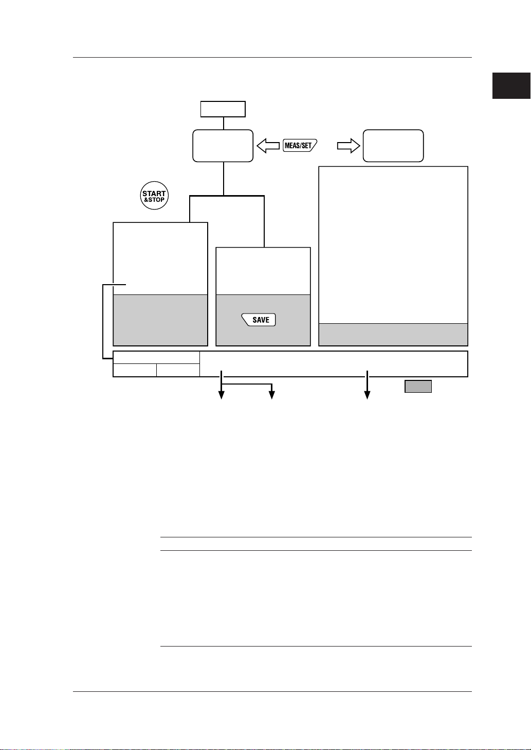
● Schematic Function Diagram
Power-on
1.1 Product Overview
1
Product Overview
Measurement
screen
key
Chapter 9
Electric energy (watt-hour)
measurement
Start of
integration
7.2.8 Setting integration start time
7.2.9 Setting integration stop time
End of
integration
Data saving
Auto-saving
7.2.7 Setting output interval
File: AWTH000.CSV
External control terminals
Input Output
7.2.11 Selecting communication device
key
Setting device number
7.2.1
Loading/saving settings
7.2.2
Deleting file and formatting PC card
7.2.3
Clearing electric energy count (watt-hours)
7.2.4
and resetting system
Copying and clearing backup memory
7.2.5
contents
Setting date
7.2.6
Setting output interval
Chapter 8
Instantaneous value
measurement
Data saving
key
7.2.7
Setting integration start time
7.2.8
Setting integration stop time
7.2.9
Setting whether to save data to PC card
7.2.10
Selecting communication device
7.2.11
Making communication settings
7.2.12
Setting communication protocol
7.2.13
Setting VT ratio
7.2.14
Setting CT ratio
7.2.15
Selecting probe to be used
7.2.16
Setting decimal point and unit of electric
7.2.17
energy (watt-hours)
Saving settings
File: MWTH000.CSV
Communication interface
(chosen when ordering)
7.2.2 Loading/saving setting File: WTH000.SET
RS-485RS-232
PC Printer PC
Setting
screens
Chapter 7
PC card
7.2.10 Setting whether to
save data to PC card
IM CW120-E
● On-screen Information (Measured Data)
There are two measurement modes: instantaneous measurement and
electric energy measurement. In the latter mode, the power is
continuously measured and integrated during the preset start and stop
times.
Instantaneous value measurement
Item Unit Displayed Name
Rms voltage V V1, V2, V3 (differs depending on the wiring method)
Rms current A A1, A2, A3 (differs depending on the wiring method)
Active power W W, W1, W2, W3 (differs depending on the wiring
method)
Reactive power Var Var, Var1, Var2, Var3 (differs depending on the wiring
method)
Power factor — PF, PF1, PF2, PF3: PowerFactor
(differs depending on the wiring method)
Frequency Hz Hz (input frequency of V1)
1-3
Page 17

1.1 Product Overview
Phase Wires
Single-phase two wires (1∅2W)
Single-phase three wires (1∅3W)
Three-phase three wires (3∅3W)
Three-phase four wires (3∅4W)
Single-phase tow-wires
×
2 (1∅2W×2)
Single-phase tow-wires
×
3 (1∅2W×3)
Electric energy measurement
Item Unit Displayed Name
Active electric energy Wh Wh, Wh1, Wh2, Wh3
Regenerative electric energy Wh Only saved; not displayed
Six items of instantaneous value measurement
(differs depending on the wiring
method)
The screen changes sequentially each time a cursor-movement (UP, DOWN,
LEFT, or RIGHT) key is pressed as follows (display contents differ depending
on the wiring method):
2
W
Var
A1
A2
V3
A1
W1
W2
Var1
Var2
W1
W2
W3
Var1
Var2
Var3
Displayed Item
Screen
3
PF
Hz
W
Var
A2
A3
PF1
PF2
Hz
PF1
PF2
PF3
Hz
Screen
4
Wh
TIME
PF
Hz
W
Var
Wh1
Wh2
TIME
Wh1
Wh2
Wh3
TIME
Screen
5
Wh
TIME
PF
Hz
Screen
6
Wh
TIME
Display
Position
Upper row
Lower row
Upper row
Lower row
Upper row
Lower row
Upper row
Lower row
Upper row
Lower row
Screen
1
V1
A1
V1
V2
V1
V2
V1
A1
A2
V1
A1
A2
A3
Screen
1-4
IM CW120-E
Page 18

Chapter 2. Components and Indications
2.1 Front Panel and Connector Block
● Dimensions
Connector Block
Unit: mm (approx. inches)
Front View Side View
161 (6.3)
2
Components and Indications
IM CW120-E
117 (4.6) 51 (2.0)
2-1
Page 19
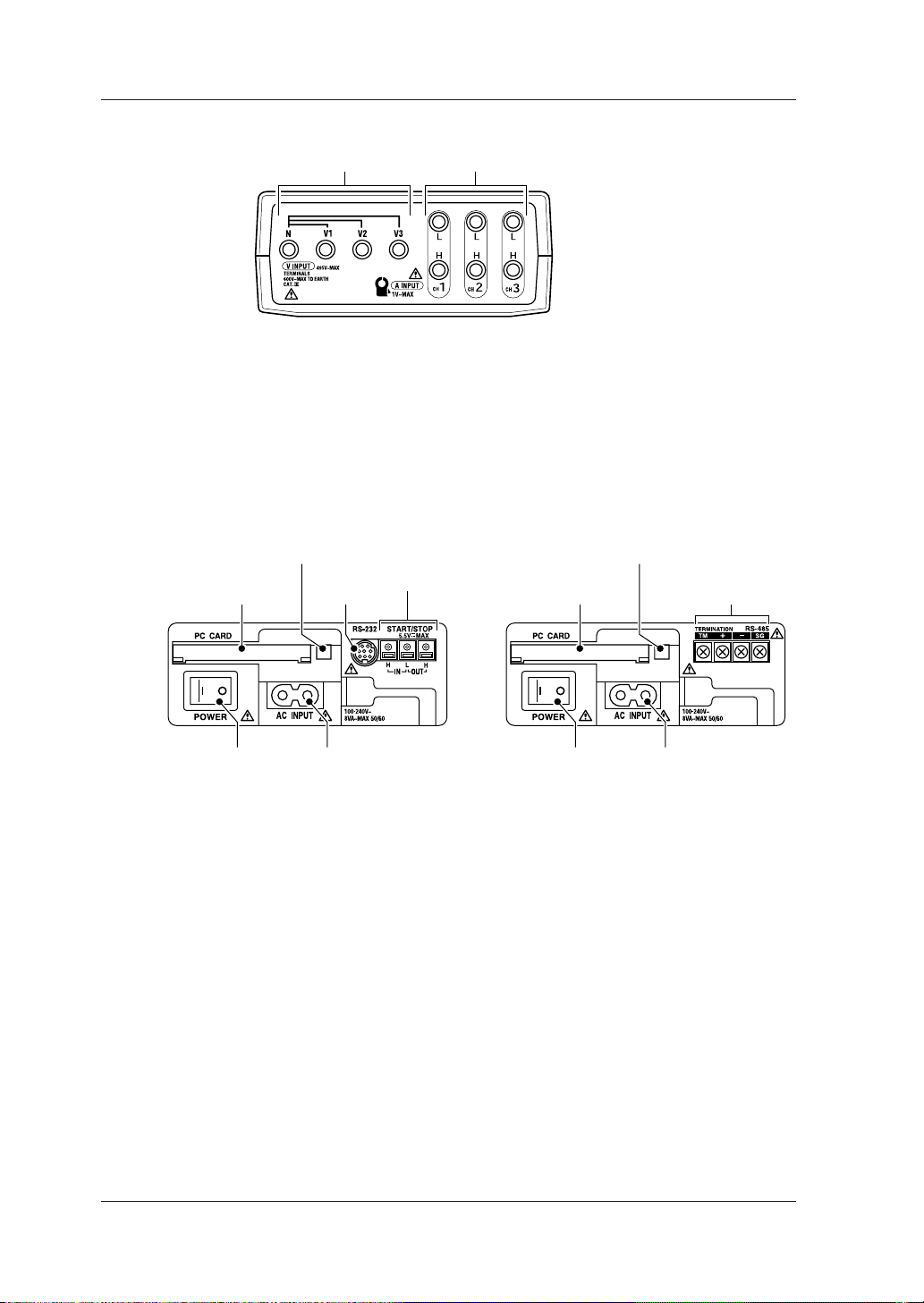
2.1 Front Panel and Connector Block
● Connector Block
Voltage input terminals Current input terminals
CW120: Supports from single-phase two-wire to three-phase three-wire circuits
Voltage input terminals: N, V1, V2
Current input terminals: CH1, CH2
CW121: Supports from single-phase two-wire to three-phase four-wire circuits
Voltage input terminals: N, V1, V2, V3
Current input terminals: CH1, CH2, CH3
● Side Panels
PC card eject button PC card eject button
PC card slot
RS-232
connector
External control
terminals
PC card slot
RS-485 screw
terminals
Power switch Power supply connector Power switch Power supply connector
Model with RS-232 interface Model with RS-485 interface
RS-232 interface
RS-232 connector : Used to connect to a PC or printer
(optional).
Internal control input (IN) terminals : Used to connect the integration
start/stop input signals.
Internal control output (OUT) terminals : Used to connect the integration
start/stop output signals.
SEE ALSO
For details of external control input/output, see Section 9.6, “External Control Input/Output.”
RS-485 interface
RS-485 screw terminals : Used to connect a shielded cable
and terminator.
SEE ALSO
For details of the RS-485 interface, see Section 11.2, “RS-485.”
2-2
IM CW120-E
Page 20

2.2 Connecting Input Signals
Ring marker
Clamp-on current probe
Voltage probe (black)
Voltage probe (red)
2
Components and Indications
WARNING
• Thoroughly read Section 5.1, “Precautions for Wiring the Circuit under Test.”
•When connecting the CW120/121, turn off the circuit under test. It is extremely dangerous to
connect or disconnect probes to/from a live circuit.
• Be extremely careful not to connect any voltage-mode circuit to the current input terminals or
any current-mode circuit to the voltage input terminals. Miswiring can result in not only damage to the circuit or equipment under test but also injury to personnel.
• Do not connect any probes which are not necessary (i.e., not used) for the current measurement, even though multiple probes can be connected to the CW120/121 at the same time.
• Do not use any probe other than the clamp-on current probes or voltage probes supplied.
• Do not use a clamp-on current probe for a non-insulated conductor.
• Ensure that the rating of the clamp-on current probe you use matches the rating of the measured current.
• Before connecting a clamp-on current probe to the CW120/121, make sure the plug is inserted
with the correct H/L polarities.
IM CW120-E
2-3
Page 21

2.2 Connecting Input Signals
● Differentiating between Voltage Probes
Voltage probes are differentiated by color for correct connections.
• Probe for terminal N: Probe with a black alligator plug
• Probes for terminals V1 to V3: Probes with a red, yellow, or blue alligator
plug
Accompanying probes
CW120: Three (black, red, and yellow)
CW121: Four (black, red, yellow, and blue)
● Differentiating between Clamp-on Current Probes
Use accompanying ring markers (of four different colors) to differentiate
clamp-on current probes for correct connections.
CW120: Terminals CH1 to CH2
CW121: Terminals CH1 to CH3
Use of Ring Markers
Attach ring markers of the same color to both ends of the probe cable for easy
identification.
CAUTION
Be careful not to damage a probe when attaching ring markers.
2-4
IM CW120-E
Page 22
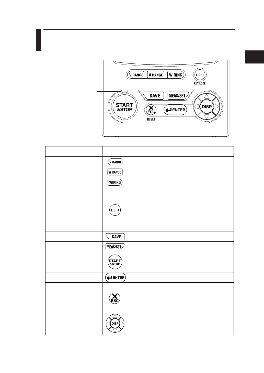
2.3 Operation Keys and Display
Integration status
LED indicator
V RANGE key
A RANGE key
WIRING key
LIGHT key
● Keys
2
Components and Indications
Key Symbol DescriptionName
Used to set and change the voltage range.
Used to set and change the current range.
Used to set and change the wiring method
(phase lines).
Also used to check the wiring. Pressing this key for three
seconds or more accesses the wiring check screen.
Switches on/off the backlight of the LCD.
Also used to lock and unlock the keys. Pressing this key
for three seconds locks the keys. To unlock,
press the key again for three seconds or more.
SAVE key
MEAS/SET key
START&STOP key
ENTER key
ESC (escape) key
Cursor movement keys
(UP/DOWN/LEFT/RIGHT keys)
Integration status LED indicator: Lit when the integration is carried out, and flashes when it is on stand-by.
IM CW120-E
Saves the measured data during instantaneous
value measurement.
Switches over the display between the measurement
and setting screens.
Starts and stops integration.
Confirms an entry such as a change to a setting.
Cancels a setting and returns to the preceding screen.
Also used to clear the electric energy count (watt-hours).
Pressing this key for three seconds or more accesses
the screen for clearing the electric energy count.
In measurement screen: Switches the display contents.
In setting screen: Changes the selection or number, or
moves the cursor position (flashing digit) over digits.
2-5
Page 23
2.4 Overrange and Other Marks Shown during Measurement
WARNING
When the overrange mark appears with the range set to a maximum, it means that the input
exceeds the maximum allowable level of the CW120/121. Do not apply an input level higher than
the maximum allowable input level.
CAUTION
When measuring an input signal level exceeding the rated range, use a voltage transformer (VT)
or current transformer (CT). When using a VT or CT, thoroughly read Section 5.3, “Wiring the
Circuit under Test with External VT/CT.”
● Overrange Indications
: Indicates an overvoltage.
This mark appears in the following conditions.
150/300 V range: If the sampled value exceeds 200% of the rated
voltage or if the rms value of the measured voltage
exceeds 110% of the rated range
450 V range: If the sampled value exceeds 156% of the rated
voltage or if the rms value of the measured voltage
exceeds 110% of the rated range
: Indicates an overcurrent.
This mark appears if the sampled value exceeds 300% of the rated
current or if the rms value of the measured current exceeds 110% of
the rated range.
TIP
The mark appears when any one of the input signals from terminals V1 to V3 satisfies the conditions noted above.
The mark appears when any one of the input signals from terminals CH1 to CH4 satisfies the
conditions noted above.
indication
The CW120/121 show instead of a usual number representing the
measured value if any one of the following conditions is met.
The number representing the measured value exceeds 9999, the maximum
number displayed.
2-6
IM CW120-E
Page 24
2.4 Overrange and Other Marks Shown during Measurement
Voltage - 150/300 V range:
If the sampled value exceeds 200% of the rated voltage or if the rms value of
the measured voltage exceeds 130% of the rated range
Voltage - 450 V range:
If the sampled value exceeds 156% of the rated voltage or if the rms value of
the measured voltage exceeds 110% of the rated range
Current:
If the sampled value exceeds 300% of the rated voltage or if the rms value of
the measured voltage exceeds 130% of the rated range
● Indications When the Measured Value Is Too Small
2
Components and Indications
Displayed Item
Voltage
Current
Active power
Reactive power
Active electric energy
Displayed Item
Reactive power
Power factor
Frequency
Condition
≤1.5 V
≤0.4% of rated range
≤0.17% of rated range
≤0.17% of rated range
≤0.17% of rated range
Condition
V1 input ≤10% of rated range; or frequency
≤40 Hz or ≥70 Hz
The voltage or current is displayed as ; or
V1 input ≤10% of rated range; or frequency
≤40 Hz or ≥70 Hz
≤40 Hz or ≥70 Hz
Indication
0 V
0 A
0 W
0 Var
0 Wh (integration stopped)
Indication
---- Var
---- PF
---- Hz
TIP
Even when an instantaneous value is displayed as , the integration calculation is carried out continuously. The accuracy of the electric energy value, however, is undefined in this case.
IM CW120-E
2-7
Page 25

2.4 Overrange and Other Marks Shown during Measurement
● Indications of Setting Items
Mark appearing during setting mode:
Setting Item Displayed Mark
1. Device number
2. Loading and saving of settings
3. Deletion of measured-data file and formatting of PC card
4. Clearance of electric energy count (watt-hours) and resetting of system
5. Copying and clearance of backup memory
6. Date
7. Output interval
8. Integration start date and time
9. Integration stop date and time
10. Whether to save data to PC card
11. Selection of communication device
12. Communication settings
13. Communication protocol setting
14. VT ratio setting
15. CT ratio setting
16. Probe selection
17. Decimal position and unit selections for electric energy (watt-hours)
● Indications during Measurement
Displayed Mark
Lights when integration is carried out; flashes when integration is on standby.
Lights when integration is controlled by external signals.
Lights when PC card memory is full.
Lights when the backup memory contains data.
Lights when the battery voltage is low.
Lights when the keys are locked.
Lights when data saving to the PC card is enabled; flashes during access
to the PC card.
Flashes during access to the PC when a PC is selected as the
communication device.
Flashes during access to the printer when a printer is selected as the
communication device.
Lights when the VT ratio is set at a value other than 1.
Lights when the CT ratio is set at a value other than 1.
2-8
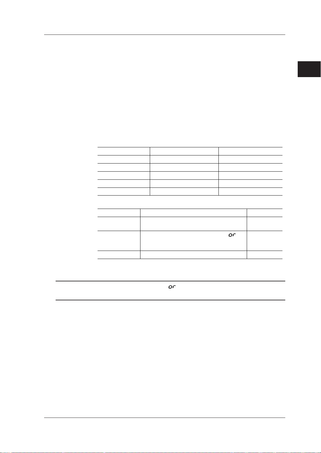
Indications for current settings of voltage range, current range, and wiring
method:
Wiring method
Voltage range
Current range
IM CW120-E
Page 26

2.4 Overrange and Other Marks Shown during Measurement
● Meanings of Messages
Displayed Message Meaning
Appears during standby of integration when set to start at a set date and time.
Appears during standby of integration when a past point of time is set as the
integration start time and date and integration will begin at the nearest
appropriate time (determined by the output interval).
Appears when integration has finished normally with the set integration
start/stop dates and times.
Appears when a power failure has occurred (or the power has been turned off)
during standby or integration.
Appears when the backup data is copied from the backup memory to the PC
card.
Appears when a PC card is not inserted.
Shows the file number and data record number when saving measured
instantaneous values.
Shows the file number when integration begins in the case that data saving to
a PC card is enabled but the filename is not specified.
Appears when integration begins in the case that data saving to a PC card is
enabled and the filename is specified. The digits following “FILE” indicate
“defined.”
2
Components and Indications
IM CW120-E
2-9
Page 27

Chapter 3. Precautions for Safe Measurement
3.1 Handling Precautions
If you are a first-time user, be sure to read “Precautions for Safe Use of
Instrument” on pages 4 and 5, Section 5.1, “Precautions for Wiring the Circuit
under Test,” and Section 5.3, “Wiring the Circuit under Test with External VT/
CT.”
● Do not place any load on the instrument.
Do not place any other equipment of a vessel filled with water on the
instrument. Otherwise, the instrument may become defective.
● Moving the instrument
Before moving the instrument, make sure the power cord and all other cables
are disconnected.
● Input Terminals
Do not bring any electrified substance close to the signal terminals.
Otherwise, the internal circuitry may be destroyed. Do not apply any
mechanical shock to the signal terminals. Otherwise, such impact may be
transformed into electrical noise and input to the instrument.
3
Precautions for Safe Measurement
● Protection of Case and Operation Panel
Do not spray any volatile chemical on the case or operation panel. Do not
leave any rubber or vinyl product in contact with the instrument for a
prolonged period. Otherwise, the instrument may be discolored or deformed.
● Cleaning
When cleaning the case and/or operation panel, disconnect the power cord
from the outlet. Then, wipe the surfaces of the case and/or operation panel
with a soft clean cloth. Do not use chemicals such as benzine or paint thinner.
Otherwise, the instrument may be discolored or deformed.
● Display Screen
When the instrument is shipped from the factory, the display screen is
covered with a protective film. Remove the film before you begin using the
instrument.
IM CW120-E
3-1
Page 28

3.1 Handling Precautions
● After Use
After use, disconnect the power cord from the outlet.
Precautions for Use of the Clamp
CAUTION
• The clamping CT (current transformer) is precision assembled to ensure high performance.
When using the clamp, do not apply any intense mechanical shock, vibration or force to the
clamping CT.
• If dust or any other foreign matter gets in the clamping CT, do not shut the clamping cores
tight. First remove the dust and then make sure the clamping cores on both sides close
smoothly.
3-2
IM CW120-E
Page 29
3.2 Installation Procedure
Install the CW120/121 in a location that satisfies the following conditions.
● Indoors
● Ambient Temperature and Humidity
• Ambient temperature: 0°C to 50°C
• Ambient humidity: 5 to 85 % RH (no condensation)
When it is applied to UL.
• Ambient temperature: 0°C to 40°C
• Ambient humidity: 5 to 85 % RH (no condensation)
Maximum relative humidity 80 % RH for temperature up to 31 °C
decreasing linearly to 50 % RH relative humidity at 40 °C.
● Altitude of Location
•Altitude: 2000 m or less
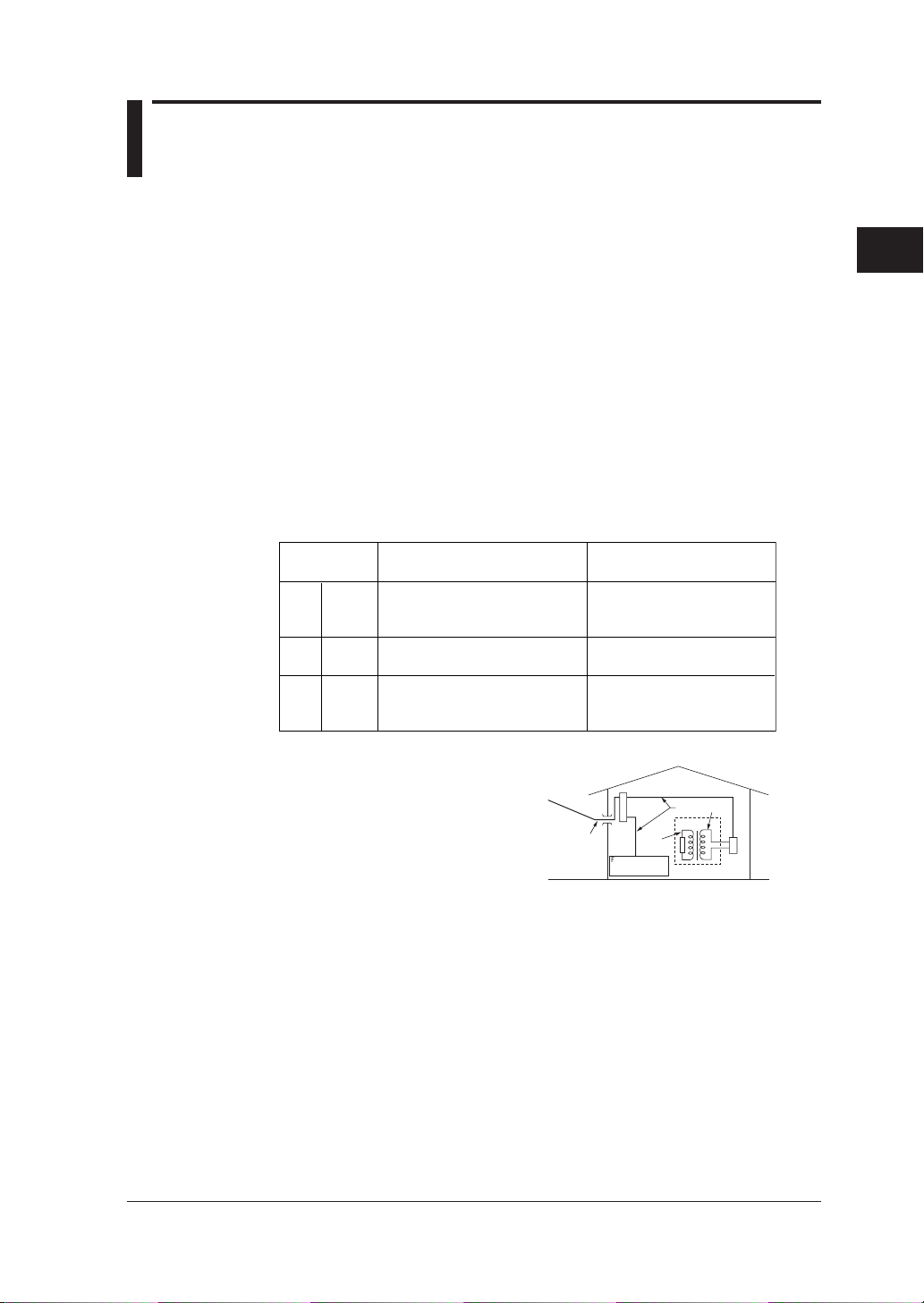
● Measurement Category (CAT.)
The measurement category of the CW120/121 is III.
Measurement
category
II
CAT.II
CAT.IIIIII
CAT.IV
IV
For measurements performed
on circuits directly connected
to the low voltage installation.
For measurements performed
in the building installation.
For measurements performed
at the source of the low-voltage
installation.
3
Precautions for Safe Measurement
DescriptionRemarks
Appliances, portable
equipments, etc.
Distribution board, circuit
breaker, etc.
Overhead wire, cable
systems, etc.
IM CW120-E
Entrance
Cable
CAT.4
Internal Wiring
Distribution
Board
CAT.1
Fixed Equipment,
etc.
CAT. 111
T
Equipment
CAT. 11
Outlet
3-3
Page 30
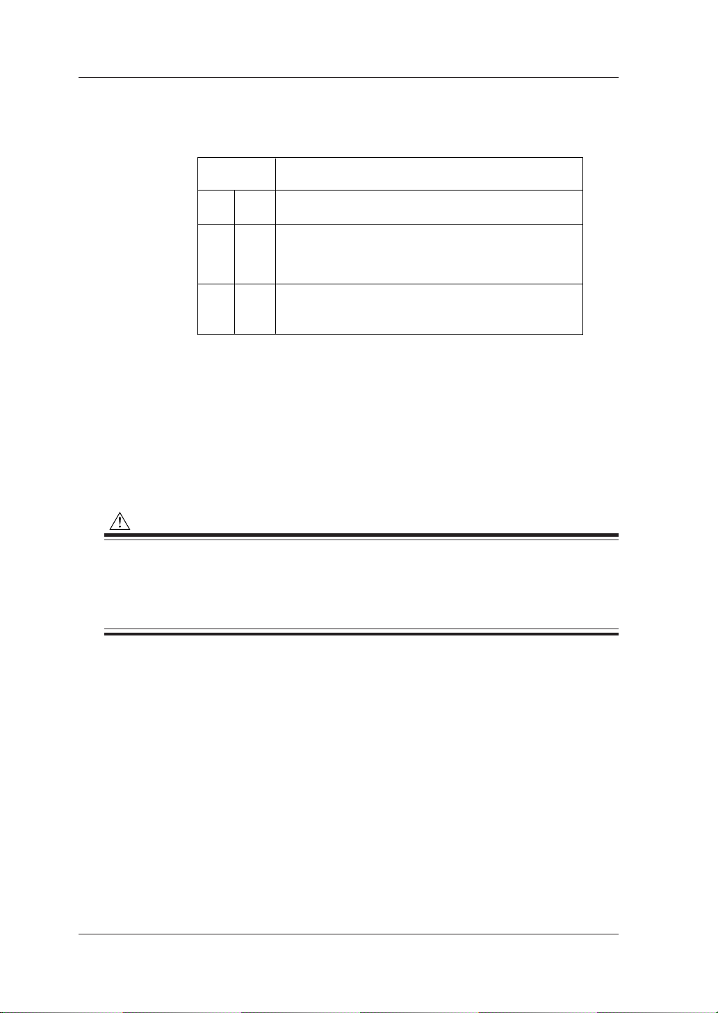
II
III
IV
CAT.II
CAT.III
CAT.IV
Instrallation
Category
Applies to electrical equipment wihch is supplied form the
fixed installation like distribution board.
Applies to electrical equipment which is power-supplied from
a cable way ranging from the primary stage and branch point
of equipment directly introducing electricity form a distribution
board to the wall outlet.
Applies to electrical equipment which is power-supplied form
a cable way ranging from the entrance cable of a building to
a primary overcurrent protection.
Description
3.2 Installation Procedure
● Installation Category (CAT.)
• Voltage measurement circuit: CAT.III (Max. input voltage: 600 Vrms)
• Power supply : CAT.II (Max. input voltage: 264 Vrms
● Pollution Degree
“Pollution degree” describes the degree to which a solid, liquid, or gas
which deteriorates dielectric strength or surface resistivity is adhering.
“2” applies to normal indoor atmosphere.
Normally, only non-conductive pollution occurs. Occasionally, however,
temporary conductivity caused by condensation must be expected.
The CW120/121 meet the “Pollution degree 2”.
CAUTION
•When using or installing two or more CW120/121 power meters, leave a distance of at least 10
mm (0.4") between them.
•When putting a power meter inside a power distribution panel or the like, leave a space of at
least 10 mm (0.4") from a wall and ensure that excess pressure may not be applied to the
protruding plugs and jacks on the terminals.
● Level Location
Do not install the CW120/121 in an unstable or inclined location;
inaccurate measurements may result.
● Other Conditions
Do not install the CW120/121 in a location that is:
• exposed to direct sunlight or close to a heat source;
•close to a noise source such as high-voltage equipment or a power
source;
• exposed to a relatively large amount of lampblack, steam, dust, or
corrosive gas;
• exposed to frequent mechanical vibration;
3-4
•close to a source of strong electromagnetic fields; or
• unstable.
IM CW120-E
Page 31

3.3 Maintaining High Precision of Measurement
To achieve a high precision of measurement, use the CW120/121 under the
following conditions.
• Ambient temperature: 23° ±5°C
• Ambient humidity: 35 to 75% RH (no condensation)
When installing the CW120/121 in a location where the ambient relative
humidity is 30% or less, use such equipment as an anti-static mat to prevent
electrostatic discharge.
If you move the CW120/121 from an area of low temperature and humidity to
an area of high temperature and humidity or if there is a sudden change in the
ambient temperature, condensation may occur in the meter. If this happens,
let the meter stand for at least one hour to allow it to adapt to the new ambient
temperature and for condensation to evaporate. Then, start operating the
meter.
● Relationship between Clamp and Conductor
1. When performing a measurement, hold the clamp-on probe so that the
conductor cable runs through the center of the clamping CT.
2. Ensure that the orientation of the clamp to the direction of the conductor
cable (from the power supply to the load) is correct, as shown in the figure.
3. Ensure that the clamping CT is properly closed.
3
Precautions for Safe Measurement
IM CW120-E
Conductor cable
Joint section
Clamping CT
Power supply source side
Load side
3-5
Page 32

Chapter 4. Connecting Power Supply and Turning Power On/Off
4.1 When Using AC Power Supply
● Before Connecting Power Supply
There is a danger of electric shock or damage to the meter. Observe the
following warning notes.
WARNING
• Use only the dedicated power cord supplied by the manufacturer.
• Before connecting the power cord, make sure the power-source voltage matches the rated
supply voltage.
• Before connecting the power cord, also make sure the power switch of the CW120 or CW121 is
turned off.
• If the CW120 or CW121 will not be used for a prolonged period, disconnect the power cord
from the outlet.
• Do not place any load on the power cord or allow the power cord to come into accidental
contact with a heat source.
• Be sure to hold the plug of the power cord, rather than holding and pulling the cord itself,
when disconnecting it from the outlet.
● Procedure for Connecting Power Cord
Follow the steps below to connect the power cord.
1. Make sure the power switch of the CW120/121 is turned off.
2. Plug one end of the power cord supplied with the CW120/121 into the
power supply jack on the side of the CW120/121.
3. Plug the other end of the power cord into a power outlet that meets the
requirements below.
Required Power Ratings
Rated supply voltage 100 to 240 V AC
Allowable supply voltage range 90 to 264 V AC
Rated power supply frequency 50 or 60 Hz
Allowable supply frequency range 48 to 63 Hz
Maximum power consumption 8 VA (at 240 V AC)
4
Connecting Power Supply and Turning Power On/Off
IM CW120-E
4-1
Page 33

4.1 When Using AC Power Supply
NOTE
•When plugging and unplugging the power cord into/from the CW120 or CW121, ensure that the
PC card eject button is depressed.
• The CW120 or CW121 will not work if the fuse built into the power supply circuit of the CW120
or CW121 has blown.
• Built-in fuses cannot be replaced by the user . For replacement, contact the vendor fr om which
you purchased the instrument.
4-2
IM CW120-E
Page 34

4.2 When Supplying Power from Voltage
Input
NOTE
The 98030 power supply cable is not applicable to CE and UL.
● Before Connecting Power Supply
There is a danger of electric shock or damage to the meter. Observe the
following warning notes.
WARNING
• Use only the optional power cable (part No. 98030) supplied by the manufacturer.
•Make sure the voltage of the circuit to be measured matches the rated supply voltage (i.e., 100
to 240 V AC).
• Before connecting to the circuit to be measured, make sure the power to the circuit is turned
off.
• Before connecting the power cable, make sure the power switch of the CW120 or CW121 is
turned off.
• Do not place any load on the power cord or allow the power cord to come into accidental
contact with a heat source.
● Procedure for Connecting 98030 Power Supply Cable
Follow the steps below to connect the 98030 power supply cable.
1. Make sure the power switch of the CW120/121 is turned off.
2. Insert the plug of the 98030 power supply cable into the power supply jack
on the side of the CW120/121.
3. Insert the black banana plug of the power supply cable into terminal N of
the CW120/121, and red banana plug into terminal V1.
4. Connect the black plug of the voltage probe to the black banana plug, and
the red plug of the probe to the red banana plug.
5. Check that the power to the circuit to be measured is turned off, and then
connect the voltage probes to the circuit.
4
Connecting Power Supply and Turning Power On/Off
IM CW120-E
Black
Voltage probe(Black)
Red
Voltage probe(Red)
4-3
Page 35

4.3 Startup Screens
Upper: Model number
Lower: V ersion number
Upper: Rms voltage
Lower: Rms current
When you turn on the power to the CW120 or CW121, the screens shown in
(1) to (3) below appear sequentially in order.
(1) All-segment On
All segments light for approximately 2 seconds, then the screen changes
to the model and version display.
(2) Model and Version Display Screen
4-4
While the display is turning on all segments and showing the model and
version numbers, the CW120/121 performs a self-test. If no error is found,
the measurement screen appears.
(3) Measurement Screen
Example of measurement screen
IM CW120-E
Page 36

● Self-test Details and Error Handling
Test Items and Errors
4.3 Startup Screens
No.
1
2
3
4
5
Test Item
Backup SRAM check
EEPROM check
Real-time clock check
@
Setting check
External memory controller check
Error Number(s)
to
to
to
If an error is found during the self-test, an error number is displayed. Confirm
the error number and press any key, then the screen changes to the
measurement screen.
NOTE
• If an error is found with any of test item Nos. 1, 3, and 4 (backup SRAM check, real-time clock
check, and setting check), the settings, date, and time will be initialized.
• The above situation may occur when the backup battery has become flat. When the (low
battery) sign is displayed on the screen, the backup battery needs to be replaced.
• The backup battery cannot be replaced by the user . For replacement, contact the vendor from
which you purchased the instrument.
• The backup battery life is about 10 years.
4
Connecting Power Supply and Turning Power On/Off
SEE ALSO
For details of errors and the countermeasures, see Chapter 13, “Troubleshooting.”
IM CW120-E
4-5
Page 37

4.4 Basic Operation Flow
Connect power supply
to CW120/121
Turn on power to
CW120/121
Startup screens
Measurement screen
key
Setting screen
key
Measurement
screen
: Calls up wiring setting
key
: Calls up voltage range setting
key
: Calls up current range setting
key
Chapter 4
Chapter 4
Chapter 4
When no setting is needed
Chapter 7
Chapter 6
4-6
Perform wiring
: Check wiring for error
key
(press 3 sec)
key
Check result
screen
key
Measurement
Instantaneous value measurement
Electric energy measurement
Chapter 5
When skipping wiring check
Chapter 5
Chapter 8
Chapter 9
IM CW120-E
Page 38

Chapter 5. Wiring
5.1 Precautions for Wiring the Circuit under Test
WARNING
•When wiring the CW120 or CW121, or when it is turned off, turn off the circuit under test. It is
highly dangerous to connect or disconnect voltage or clamp-on current probes without first
turning off the circuit under test.
• Be extremely careful not to connect any voltage-mode circuit to the current input terminals or
any current-mode circuit to the voltage input terminals. Miswiring can result in not only damage to the circuit under test or equipment under test but also injury to personnel.
• Do not apply any input level higher than the following to the voltage or current input terminals
(the upper limit differs depending on the probe used):
Maximum allowable input (continuous)
Voltage input: 495 Vrms
Current input –for 96033 probe: 130 Arms
for 96030 probe: 250 Arms
for 96031 probe: 625 Arms
for 96032 probe: 700 Arms (1000 Arms for 5 minutes)
Input ratings for each range
Voltage input: 150/300/450 V
Current input –for 96033 probe: 5/10/20/50 A
for 96030 probe: 20/50/100/200 A
for 96031 probe: 50/100/200/500 A
for 96032 probe: 200/500/1000 A
5
Wiring
SEE ALSO
For details, see Chapter 14, “Specifications.”
WARNING
• If using an external voltage transformer (VT) or current transformer (CT), make sure the transformer can adequately withstand the voltage being measured. Be extremely careful not to
allow the secondary stage of the CT to become open-circuited while the CT is being electrified.
Otherwise, a high-voltage may develop on the secondar y stage, causing extreme danger.
• The maximum allowable input voltage range of the external control input terminals is -0.5 to
5.5 V. Do not apply voltages exceeding this range, otherwise the input circuitry may be damaged. (When wiring the input terminals, ensure that you wire the right terminals.)
• Do not use any probe other than the voltage probes supplied with the CW120/121 or dedicated
clamp-on current probes.
• Do not use a clamp-on probe with any non-insulated conductors.
IM CW120-E
5-1
Page 39

5.2 Diagrams of Basic Wiring
This section explains the methods of basic wiring using illustrations.
Single-phase two wires (1∅2W)
SOURCE LOAD
1
N
NV1 CH1
Single-phase three wires (1∅3W)
SOURCE LOAD
1
N
2
NV1V2 CH1 CH2
Three-phase three wires (3∅3W)
SOURCE LOAD
1
2
3
5-2
NV1V2 CH1 CH2
Three-phase four wires (3∅4W): Only for CW121
SOURCE LOAD
N
1
2
3
NV1V2V3 CH2CH1 CH3
Single-phase tow-wires ×2 (1∅2W ×2)
SOURCE LOAD1
1
N
NV1 CH2CH1
LOAD2
IM CW120-E
Page 40

5.2 Diagrams of Basic Wiring
Single-phase tow-wires ×3 (1∅2W ×3): Only for CW121
1
N
SOURCE
LOAD1
LOAD2
LOAD3
NV1 CH2CH1 CH3
The table below shows the correspondences between the voltage/current
units (sets of a unit + input number) displayed on the screen and the input
terminals for voltage and clamp-on current probes.
Wiring Method
(Phase Lines)
Single-phase two wires
(1∅2W)
Single-phase three wires
(1∅3W)
Three-phase three wires
(3∅3W)
Three-phase four wires*
(3∅4W)
Single-phase tow-wires
×2 (1∅2W ×2)
Single-phase tow-wires*
×3 (1∅2W ×3)
* Only for CW121
Voltage Inputs
Terminals: N-V1
Units: V1
Terminals: N-V1, N-V2
Units: V1, V2
Terminals: N-V1, N-V2
Units: V1, V2
Terminals: N-V1, N-V2, N-V3
Units: V1, V2, V3
Terminals: N-V1
Units: V1
Terminals: N-V1
Units: V1
Current Inputs
Terminals: CH1
Units: A1
Terminals: CH1, CH2
Units: A1, A2
Terminals: CH1, CH2
Units: A1, A2
Terminals: CH1, CH2, CH3
Units: A1, A2, A3
Terminals: CH1, CH2
Units: A1, A2
Terminals: CH1, CH2, CH3
Units: A1, A2, A3
5
Wiring
IM CW120-E
5-3
Page 41

5.3 Wiring the Circuit under Test with External VT/CT
WARNING
•When using an external current transformer (CT), be careful not to allow the secondary stage
of the CT to become open-circuited while the primary stage is being electrified. Otherwise, a
high-voltage may develop on the secondary stage, causing extreme danger.
•A measuring current flows through the bold lines shown in the figure below. For these lines,
use wires having an adequate margin of current-carrying capacity.
If the maximum voltage or current level being measured exceeds the
maximum measurement range of the CW120/121, use an external voltage
transformer (VT) or current transformer (CT). This strategy enables the
voltage or current levels beyond the maximum range to be measured.
When to use a VT and how?
If the maximum voltage of the circuit exceeds 450 V, connect an external VT
and connect the secondary stage of the VT to the voltage input terminals.
When to use a CT and how?
If the maximum current of the circuit exceeds the following value, connect an
external CT and clamp the secondary stage wire of the CT with a current
probe.
96033 probe: 50 A (rated at 5/10/20/50 A)
96030 probe: 200 A (rated at 20/50/100/200 A)
96031 probe: 500 A (rated at 50/100/200/500 A)
96032 probe: 1000 A (rated at 200/500/1000 A)
Example for single-phase two wires (1∅2W)
1
Source Load
N
V
VT CT
v
V1Voltage input Current inputN CH1
L
Scaling
When using a VT and/or CT, you can set the VT ratio and/or CT ratio to
display the readings of the primary circuit voltages and currents. (This is
called the scaling function.)
SEE ALSO
For details of how to set the CT and VT ratios, see Sections 7.2.14 and 7.2.15, “Setting VT Ratio” and
“Setting CT Ratio.”
5-4
IM CW120-E
Page 42

5.4 Indication and Change of Wiring
Method
The abbreviations for wiring methods are labeled immediately above the
screen as 1∅2W, 1∅3W, 3∅3W, 3∅4W, 1∅2W2, and 1∅2W3 (3∅4W,
1∅2W3 are not included for the CW120), and the sign on the screen
indicates the wiring method currently selected in the CW120/121.
Wiring methods
WIRING
WIRING key
5
Wiring
IM CW120-E
To change the wiring method, press the key. Each time you press the
WIRING key, the moves to change the selected wiring method.
Indication of wiring method.
<1∅2W ×2>
CW120
<1∅2W ×3>
CW121
CW121
5-5
Page 43

5.5 Wiring Check Function
WARNING
• It is important to check the wiring for correct and safe measurement. Check the wiring with
reference to Chapter 3, “Precautions for Safe Measurement,” Section 5.1, “Precautions for
Wiring the Circuit under Test,” and Section 5.3, “Wiring the Circuit under Test with External VT/
CT.”
• Check the connections of voltage probes, and for clamp-on current probes, check the models
(ratings), H/L polarities of the plugs and jacks, and the arrow symbols on the clamps corresponding to the source-to-load directions of the circuit.
• Do not use a clamp-on current probe with any non-insulated conductor.
● Check Items
The following items are checked and judged, and then the result of each
check item will be displayed as shown on the next page.
For each voltage input: For each current input:
1. Existence of input voltages 1. Existence of input currents
2. Frequency detection 2. Clamp directions
3. Voltage phase sequence
NOTE
•Measurement is not performed during the wiring check.
• The wiring check cannot be carried out during continuous measurement.
5-6
IM CW120-E
Page 44

● Check Items and Criteria
Voltage Inputs
5.5 Wiring Check Function
Item
1. Existence of voltage
inputs
2. Frequency detection
3. Voltage phase
sequence
Item
1. Existence of input
currents
2. Clamp directions
Criteria
• If an input level is 10% or less of the range,
then an error results.
• Else, the frequency detection takes place.
• If the frequency of input V1 exceeds the 40 to
70 Hz range, then an error results.
• Else, the voltage phase sequence check takes
place.
For 1∅2W or 1∅3W:
• This item is not checked.
For 3∅3W:
• If V2 leads V1 by more than approximately 80
degrees or less than approximately 40 degrees,
an error results.
For 3∅4W (only for the CW121):
• If V2 lags behind V1 by more than
approximately 140 degrees or less than
approximately 100 degrees, an error results.
• Or if V3 leads V1 by more than approximately
140 degrees or less than approximately 100
degrees, an error results.
• Else, “Good” is displayed.
Current Inputs
Criteria
• If an input level is 1% or less of the range, then
an error results.
• Else, the clamp direction check takes place.
• For any wiring method other than 3∅3W, if the
power of one or more phases is negative, an
error results.
• For 3∅3W, if the whole power is negative, an
error results.
• Else, “Good” is displayed.
Error Message
(in lower row)
Error message
Error message
Error message
Error Message
(in lower row)
Error message
Error message
V
Hz
5
Wiring
V
V
A
A
A
NOTE
• As the wiring is judged on the above criteria, an error may result even when wiring is correct or
wrong wiring may pass the check.
•When a measured value appears to be abnormal, check the above criteria and wiring again.
IM CW120-E
5-7
Page 45

5.5 Wiring Check Function
● Carrying out Wiring Check
(1) When the measurement screen is displayed, press the key for at
least three seconds, and “ ” appears on the screen and flashes.
START
&STOP
(2) Press the key. Then, “ ” stops flashing and the wiring check
begins.
WIRING
Press WIRING key for
at least three seconds.
START&STOP key
(3) When no error has been found, “ ” is displayed on both the upper
and lower rows. Press the key to return to the measurement screen.
When no error
Upper: Judgment of current inputs
Lower: Judgment of voltage inputs
WIRING
WIRING key
START
&STOP
START&STOP key
5-8
IM CW120-E
Page 46

5.5 Wiring Check Function
When an error is displayed, refer to the table on page 5-8 and check the
meaning of the error. Check and correct the connections, then press the
key to carry out the wiring check again.
To return to the measurement screen, press the
Example of error indications
Upper: No current input
Lower: Voltage phase sequence error
( when frequency error)
WIRING
WIRING key
START
&STOP
START&STOP key
key.
5
Wiring
IM CW120-E
5-9
Page 47

Chapter 6. Setting Ranges and Wiring Method
6.1 Ranges and Display Digits
The following describes the voltage, current, power, and electric energy
ranges.
● Voltage Range
150/300/450 V
● Current Range
96033 clamp-on probe: 5/10/20/50 A
96030 clamp-on probe: 20/50/100/200 A
96031 clamp-on probe: 50/100/200/500 A
96032 clamp-on probe: 200/500/1000 A
● Range of Active and Reactive Powers
The range of active and reactive powers is determined by the voltage
range, current range, and wiring method set as follows:
6
Setting Ranges and Wiring Method
Wiring Method (Phase Lines)
Single-phase two wires
Single-phase tow-wires × 2
Single-phase tow-wires × 3*
Single-phase three wires
Three-phase three wires
Three-phase four wires*
*Only for CW121
Power Range
Voltage range × current range
Voltage range × current range × 2
Voltage range × current range × 3
IM CW120-E
6-1
Page 48

6.1 Ranges and Display Digits
● Range Table (Table of Full Scales) – Rated Power
The table below shows the rated powers corresponding to combinations
of voltage and current ranges.
Voltage
(V)
Range
150 V
300 V
450 V
* Only for CW121
Phase
Lines
1∅2W
1∅2W ×2
1∅2W ×3*
1∅3W
3∅3W
3∅4W*
1∅2W
1∅2W ×2
1∅2W ×3*
1∅3W
3∅3W
3∅4W*
1∅2W
1∅2W ×2
1∅2W ×3*
1∅3W
3∅3W
3∅4W*
96033 Probe (5–50 A)
5.000 A
750.0 W
1.500 kW
1.500 kW
2.250 kW
1.500 kW
3.000 kW
3.000 kW
4.500 kW
2.250 kW
4.500 kW
4.500 kW
6.750 kW
10.00 A
1.500 kW
3.000 kW
3.000 kW
4.500 kW
3.000 kW
6.000 kW
6.000 kW
9.000 kW
4.500 kW
9.000 kW
9.000 kW
13.50 kW
Current (A) Range
96031 Probe (50–500 A)
96030 Probe (20–200 A)
20.00 A
3.000 kW
6.000 kW
6.000 kW
9.000 kW
6.000 kW
12.00 kW
12.00 kW
18.00 kW
9.000 kW
18.00 kW
18.00 kW
27.00 kW
50.00 A
7.500 kW
15.00 kW
15.00 kW
22.50 kW
15.00 kW
30.00 kW
30.00 kW
45.00 kW
22.50 kW
45.00 kW
45.00 kW
67.50 kW
100.0 A
15.00 kW
30.00 kW
30.00 kW
45.00 kW
30.00 kW
60.00 kW
60.00 kW
90.00 kW
45.00 kW
90.00 kW
90.00 kW
135.0 kW
96032 Probe (200–1000 A)
200.0 A
30.00 kW
60.00 kW
60.00 kW
90.00 kW
60.00 kW
120.0 kW
120.0 kW
180.0 kW
90.00 kW
180.0 kW
180.0 kW
270.0 kW
500.0 A
75.00 kW
150.0 kW
150.0 kW
225.0 kW
150.0 kW
300.0 kW
300.0 kW
450.0 kW
225.0 kW
450.0 kW
450.0 kW
675.0 kW
1.000 kA
150.0 kW
300.0 kW
300.0 kW
450.0 kW
300.0 kW
600.0 kW
600.0 kW
900.0 kW
450.0 kW
900.0 kW
900.0 kW
1.350 MW
TIP
For reactive power, the same table applies but the units of measurement are different.
Units of reactive power: Var, kVar, MVar
If either or both of the VT and CT ratios are set to a value other than 1, and if the product of the following
formula exceeds 9999, the decimal point is incremented by one:
Rated power in table × VT ratio × CT ratio × 1.3
6-2
IM CW120-E
Page 49

6.1 Ranges and Display Digits
Range × VT Ratio (× 1.3)*
150
1
10
100
1
to 999.9
to 9.999
to 99.99
to 999.9
to 4.5
V
kV
kV
kV
MV
Decimal Point Position and Unit
999.9
9.999
99.99
999.9
4.500
V
kV
kV
kV
MV
Decimal Point Position and Unit
9.999
99.99
999.9
9.999
99.99
999.9
9.999
10.00
Range × CT Ratio (× 1.3)*
5
10
100
1
10
100
1
to 9.999
to 99.99
to 999.9
to 9.999
to 99.99
to 999.9
to 9.999
10
A
A
A
kA
kA
kA
MA
MA
A
A
A
kA
kA
kA
MA
MA
Decimal Point Position and Unit
70.00
Input Frequency
40 to 70 Hz
Hz
Rated Power × VT Ratio × CT Ratio (× 1.3)*
to 999.9
to 9.999
to 99.99
to 999.9
to 9.999
to 99.99
to 999.9
to 9.999
to 99.99
to 999.9
to 9.999
to 99.99
to 999.9
to 9999
W
W
W
W
kW
kW
kW
MW
MW
MW
GW
GW
GW
GW
Decimal Point Position and Unit
999.9
9.999
99.99
999.9
9.999
99.99
999.9
9.999
99.99
999.9
9.999
99.99
999.9
9999
W
W
W
W
kW
kW
kW
MW
MW
MW
GW
GW
GW
GW
975
1
10
100
1
10
100
1
10
100
1
10
100
1000
* Multiply by 1.3 only when the CT or VT ratio is a value other than 1.
● Display Digits
The tables below show the display digits, decimal point positions, and
units of measurement.
Voltage – Maximum Display Digits: 4
Current – Maximum Display Digits: 4
Frequency – Maximum Display Digits: 4
Power – Maximum Display Digits: 4
6
Setting Ranges and Wiring Method
IM CW120-E
6-3
Page 50

Power Factor
–1 to 1
Decimal Point Position and Unit
1.000
6.1 Ranges and Display Digits
TIP
For reactive power, the same table as for the power applies but the units of measurement are different.
Units of reactive power: Var, kVar, MVar, GVar
Power Factor – Maximum Display Digits: 4
● Decimal Point Position and Unit for Electric Energy
The decimal point position and unit of measurement for electric energy
can be set via the screen (see Section 7.2.17, “Selecting Decimal Point
Position and Unit for Electric Energy”).
• Decimal point: Selectable from 000.000, 0000.00, 00000.0, and
000000
•Unit: Selectable from Wh, kWh, MWh, and GWh
By selecting STANDARD, you can also let the CW120/121 automatically
set them as follows.
Rated Power × VT Ratio × CT Ratio
(× 1.3)*
1 to 9.999
10 to 99.99
100 to 999.9
1 to 9.999
10 to 99.99
100 to 999.9
1 to 9.999
10 to 99.99
100 to 999.9
1 to 9.999
10 to 99.99
100 to 999.9
* Multiply by 1.3 only when the CT or VT ratio is a value other than 1.
W
W
W
kW
kW
kW
MW
MW
MW
GW
GW
GW
Decimal Point Position and Unit for Electric energy
(Max. Count)
0.00
0.0
0.000
0.00
0.0
0.000
0.00
0.0
0.000
0.00
0.0
0
to 9999.99
to 99999.9
to 999.999
to 9999.99
to 99999.9
to 999.999
to 9999.99
to 99999.9
to 999.999
to 9999.99
to 99999.9
to 999999
Wh
Wh
kWh
kWh
kWh
MWh
MWh
MWh
GWh
GWh
GWh
GWh
SEE ALSO
For the setting procedures, see Chapter 7, “Making Settings.”
6-4
IM CW120-E
Page 51

6.1 Ranges and Display Digits
When the electric energy count has reached the maximum, the count will be
reset to zero as illustrated below.
999.999 kWh
Power
0
Time
WARNING
When newly starting integrating power, clear the electric energy count (and the elapsed time of
integration). Otherwise, the electric energy count will be added to the previous value. For details
of how to clear the electric energy count, see Section 9.2.3, “Clearing Electric Energy Count,” or
Section 7.2.4, “Clearing Electric Energy Count and Resetting System,” in Chapter 7, “Making
Settings.”
6
Setting Ranges and Wiring Method
IM CW120-E
6-5
Page 52

6.2 Changing Voltage Range Setting
● Procedure to Change Voltage Range Setting
(1) The sign is displayed uppermost on the screen, under the voltage
range currently selected. To change the range, press the key when
the measurement screen is displayed.
150V 300V 450V
V
RANGE
Voltage ranges
V RANGE key
Each press of the key changes the range selection sequentially as
follows:
150 V 300 V 450 V
Default: 150 V
TIP
• If a change to the range setting is incompatible with the conditions derived from other settings,
is displayed and the change is ineffective. First change other settings such as the current range, VT
ratio, CT ratio, and wiring method, then change the voltage range.
• The voltage range cannot be changed during continuous measurement.
• The voltage range cannot be changed when the electric energy count is not zero. Pressing the
key at this time causes to appear on the screen (this will disappear and the measurement
screen will return when any key is pressed). Clear the electric energy count first. For details of how to
do this, see Section 9.2.3, “Clearing Electric Energy Count,” or Section 7.2.4, “Clearing Electric Energy
Count and Resetting System,” in Chapter 7, “Making Settings.”
6-6
IM CW120-E
Page 53

6.3 Changing Current Range Setting
● Procedure to Change Current Range Setting
(1) The sign is displayed lowermost on the screen, above the current
range currently selected. To change the range, press the key when
the measurement screen is displayed.
6
Setting Ranges and Wiring Method
5A 10A 20A 50A 100A 200A 500A 1000A
A
RANGE
Current ranges
A RANGE key
Each press of the key changes the range selection sequentially as
follows:
When the 96030 clamp-on probe is selected for use
20 A 50 A 100 A 200 A
Default: 20 A
TIP
• If a change to the range setting is incompatible with the conditions derived from other settings,
is displayed and the change is ineffective. First change other settings such as the current range, VT
ratio, CT ratio, and wiring method, then change the voltage range.
• The voltage range cannot be changed during continuous measurement.
• The voltage range cannot be changed when the electric energy count is not zero. Pressing the
key at this time causes to appear on the screen (this will disappear and the measurement
screen will return when any key is pressed). Clear the electric energy count first. For details of how to
do this, see Section 9.2.3, “Clearing Electric Energy Count,” or Section 7.2.4, “Clearing Electric Energy
Count and Resetting System,” in Chapter 7, “Making Settings.”
IM CW120-E
6-7
Page 54

6.3 Changing Current Range Setting
When the 96033 clamp-on probe is selected for use
5 A 10 A 20 A 50 A
Default: 5 A
When the 96031 clamp-on probe is selected for use
50 A 100 A 200 A 500 A
Default: 50 A
When the 96032 clamp-on probe is selected for use
200 A 500 A 1000 A
Default: 200 A
● Selecting Clamp-on Current Probe to Be Used
The current ranges that can be selected vary with the clamp-on current
probe used. The probe selection can be changed from a setting screen.
Clamp-on Current Probe Models and Ratings
Clamp-on Current Probe Model
96033
96030
96031
96032
Default: 200 A
Setting
50 A
200 A
500 A
1000 A
Rating (Ranges)
5/10/20/50 A
20/50/100/200 A
50/100/200/500 A
200/500/1000 A
Procedure to Change Probe Selection
(1) Press the key when the measurement screen is displayed. The
screen switches to the setting item selection screen and the sign
appears in the lower left of the screen.
(2) Using the keys, make the mark (in the lower right) and its
current setting appear on the screen. Then, press the key. The
number representing the currently selected clamp model flashes.
6-8
IM CW120-E
Page 55

6.3 Changing Current Range Setting
MEAS/SET key
MEAS/SET
ENTER
DISP
UP/DOWN/LEFT/RIGHT keys
ENTER key
(3)Using the keys, select the number corresponding to the
desired clamp-on current probe.
or
or
(4) Press the key.
(5) Press the key to return to the measurement screen. The range is
changed according to the new probe selected.
SEE ALSO
For details of the clamp selection, see Chapter 7, “Making Settings.”
TIP
• If a change to the clamp-on current probe selection is incompatible with the conditions derived from
other settings, the change is ineffective. First change other settings such as the voltage range, VT
ratio, CT ratio, and wiring method, then change the probe selection.
• The current probe cannot be changed during continuous measurement.
• The current probe cannot be changed when the electric energy count is not zero, and an attempt to
change causes to appear on the screen (this will disappear and the measurement screen
will return when any key is pressed). Clear the electric energy count first. For details of how to do
this, see Section 9.2.3, “Clearing Electric Energy Count,” or Section 7.2.4, “Clearing Electric Energy
Count and Resetting System,” in Chapter 7, “Making Settings.”
6
Setting Ranges and Wiring Method
IM CW120-E
6-9
Page 56

6.4 Changing Wiring Method Setting
● Procedure to Change Wiring Method Setting
(1) The sign is displayed uppermost on the screen, above the wiring
method currently selected. To change the method, press the key
when the measurement screen is displayed.
Wiring methods
WIRING
WIRING key
Each press of the key changes the wiring method selection
sequentially as follows:
For CW120
1∅2W 1∅3W 3∅3W
Default: 3∅3W
TIP
• If a change to the wiring method setting is incompatible with the conditions derived from other settings, the change is ineffective . First change other settings such as the voltage range, current range,
VT ratio, and CT ratio, then change the wiring method.
• The wiring method cannot be changed during continuous measurement.
• The wiring method cannot be changed when the electric energy count is not zero. Pressing the
key at this time causes to appear on the screen (this will disappear and the measurement
screen will return when any key is pressed). Clear the electric energy count first. For details of how
to do this, see Section 9.2.3, “Clearing Electric Energy Count,” or Section 7.2.4, “Clearing Electric
Energy Count and Resetting System,” in Chapter 7, “Making Settings.”
1∅2W ×2
6-10
IM CW120-E
Page 57

For CW121
6.4 Changing Wiring Method Setting
1∅2W 1∅3W 3∅3W
Default: 3∅3W
SEE ALSO
For details of the wiring methods, see Chapter 5, “Wiring.”
Indication of wiring method.
<1∅2W ×2>
CW120
<1∅2W ×3>
CW121
3∅4W
CW121
1∅2W ×21∅2W ×3
6
Setting Ranges and Wiring Method
IM CW120-E
6-11
Page 58

Chapter 7. Making Settings
7.1 Setting Items and Item Selection
● Setting Items
Before starting measurement, the following measurement condition and
data saving settings should be made as necessary.
Setting Item Display Mark
1. Device number
2. Loading and saving of settings
3. Deletion of measured-data file and formatting of PC card
4. Clearance of electric energy count and resetting of system
5. Copying and clearance of backup memory
6. Date
7. Output interval
8. Integration start date and time
9. Integration stop date and time
10.Data saving to PC card
11.Communication device selection
12.Communication settings
13.Communication protocol setting
14.VT ratio setting
15.CT ratio setting
16.Clamp-on current probe selection
17.Decimal point position and unit selections for electric energy
7
Making Settings
TIP
The Setting Check Sheet in the back of
their available selections. Use this sheet for grasping the setting conditions and for efficient setting on
site.
IM CW120-E
Operation Guide
(IM CW120P-E) lists necessary settings and
7-1
Page 59

7.1 Setting Items and Item Selection
● Keys Used for Setting
The keys used for setting are described below.
Device number
MEAS/SET key
UP/DOWN/LEFT/RIGHT keys
ENTER key
ESC
MEAS/SET
ENTER
DISP
ESC key
key
Used to toggle the display between measurement and setting screens.
The mark is displayed on a setting screen.
key
Used to fix a selection.
key
Used to cancel a setting. Pressing this key returns to the preceding
screen.
keys
Used to:
• Change the setting item displayed.
• Change a number.
• Change a setting.
7-2
keys
Used to:
• Change the setting item displayed.
• Select a digit.
• Change a setting.
IM CW120-E
Page 60

7.1 Setting Items and Item Selection
● Setting Procedure
(1) Press the key. The display changes from the measurement screen
to the screen for setting (the setting item selection screen) and the
sign appears in the lower left.
Device number setting screen
MEAS/SET key
UP/DOWN/LEFT/RIGHT keys
ENTER key
ESC
MEAS/SET
ENTER
DISP
7
Making Settings
ESC key
(2) Using the keys, select the desired item, and then press the
key. Each time one of the keys is pressed, the setting
item changes sequentially as follows.
or
or
To cancel a setting after pressing the key, press the key. The
setting item selection screen then returns.
(3) After making necessary changes to the settings, press the
key to
return to the measurement screen.
TIP
• The MEM (backup memory setting) is skipped if no data exists in the backup memory (and the MEM
mark is not lit on the measurement screen).
• The DEV (communication device) setting is skipped if your CW120/121 model has an RS-485 interface.
• The setting item that is selected by default when the screen changes from the measurement screen,
is the item selected last time the measurement screen was returned from a setting screen.
• In the electric energy measurement mode, the settings can be viewed only for checking and cannot
be modified.
IM CW120-E
7-3
Page 61

7.2 Setting Each Item
7.2.1 Setting Device Number ( )
Description
The device number is used for identifying each power meter (CW120/121)
when monitoring a specific power with two or more CW120s and CW121s,
and also used as the device address when using RS-485 communication.
The device number consists of three digits. It is set to 001 by default and can
be set to any number from 001 to 999.
TIP
When using RS232 communication, in cases when the communication protocol is other than CW120/
121 exclusive, Device number is used as the Device Address.
Communication protocols and device number limits
Communication Protocol Device number limits
CW120/121-dedicated communication
Power monitor (PR201) communication
PC link communication without checksum
PC link communication with checksum
MODBUS communication (ASCII mode)
MODBUS communication (RTU mode)
1 to 999
1 to 31
1 to 99
1 to 99
1 to 247
1 to 247
Procedure
(1) Using the keys in the setting item selection screen, make the
mark and its corresponding setting appear on the screen. Then, press
the key. The rightmost digit begins flashing.
Device Number Setting Screen
MEAS/SET key
UP/DOWN/LEFT/RIGHT keys
ENTER key
ESC
MEAS/SET
ENTER
DISP
ESC key
7-4
IM CW120-E
Page 62

7.2 Setting Each Item
(2) Using the keys, select the digit to be changed. The selected digit
flashes.
(3) Using the
keys, change the number of the selected digit.
(4) After making necessary changes, press the
number is then set and the setting item selection screen returns.
To cancel the changes, press the
screen also returns.
7.2.2 Loading and Saving Settings ( )
Description
Select to load settings from a PC card.
Select to save settings to a PC card.
The file number consists of three digits and can be set to any number from
000 to 029.
TIP
Name of setting file: WTH
nnn
.SET where
nnn
is the file number you set, from 000 to 029
Procedure
(1) Using the keys in the setting item selection screen, make the
mark to appear on the screen. Then, press the key.
begins flashing.
Loading/Saving Selection Screen
key. The new device
key. The setting item selection
7
Making Settings
IM CW120-E
MEAS/SET key
UP/DOWN/LEFT/RIGHT keys
ENTER key
ESC
MEAS/SET
ENTER
DISP
ESC key
(2) Using the keys, select or .
7-5
Page 63

7.2 Setting Each Item
(3) Press the key to confirm the selection. A three-digit number
appears on the lower row, allowing you to set the file number of the file to/
from which you want to save/load settings.
To cancel loading/saving, press the
key. The setting item selection
screen returns.
Loading
File Number Setting Screen for Loading
MEAS/SET key
UP/DOWN/LEFT/RIGHT keys
ENTER key
ESC
MEAS/SET
ENTER
DISP
ESC key
(4) Specify the file number in accordance with the steps below.
7-6
(5) Using the
keys, select the digit to be changed. The selected digit
flashes.
(6) Using the
(7) After making necessary changes, press the
keys, change the number of the selected digit.
key. The settings are
then loaded and the setting item selection screen returns.
You cannot select the file number of a file that does not exist. Selecting
such a file number returns to the screen for file number setting.
To cancel loading, press the key. The screen in step (1) returns.
IM CW120-E
Page 64

Saving
File Number Setting Screen for Saving
7.2 Setting Each Item
MEAS/SET key
UP/DOWN/LEFT/RIGHT keys
ENTER key
ESC
MEAS/SET
ENTER
DISP
ESC key
(4) Specify the file number in accordance with the steps below.
(5) The smallest file number within the unused numbers from 000 to 029 is
displayed.
(6) If the displayed number is fine, press the key.
(7) If you want to specify a different file number, using the
keys, select
the digit to be changed. The selected digit flashes.
(8) Using the keys, change the number of the selected digit.
(9) After making necessary changes, press the key. The settings are
then saved and the setting item selection screen returns.
You cannot select a file number that has already been used. Selecting
such a file number returns to the screen for file number setting.
To cancel saving, press the key. The screen in step (1) returns.
NOTE
•When the number of setting files residing in the inserted PC card has reached 30, you can no
longer save the settings. Attempting to save settings causes to appear (this will
disappear and the previous screen will return when any key is pressed). Delete an unnecessary file or files and try saving again.
• The loading cannot be performed when the electric energy count and the integration time are not
zero. Attempting to load settings causes to appear on the screen (this will disappear
and the measurement screen will return when any key is pressed). Clear the electric energy
count first. For details of how to do this, see Section 9.2.3, “Clearing Electric Energy Count,” or
Section 7.2.4, “Clearing Electric Energy Count and Resetting System,” in this chapter.
7
Making Settings
TIP
•When the PC card is full, the sign is displayed on the screen and the saving cannot be performed.
•Saving the settings when the communication device is set to a printer, prints the settings at the same
time.
IM CW120-E
7-7
Page 65

7.2 Setting Each Item
7.2.3 Deleting Measured-data Files and Formatting PC Card ( )
Description
Select to delete all the measured data saved in the PC card.
Select to format the PC card.
Procedure
(1) Using the keys in the setting item selection screen, make the
mark to appear on the screen. Then, press the key.
begins flashing.
Measured-data Deletion Screen PC Card Formatting Screen
MEAS/SET key
UP/DOWN/LEFT/RIGHT keys
ENTER key
ESC
MEAS/SET
ENTER
DISP
ESC key
(2) Using the keys, select if you want to delete the
measured data or if you want to format the PC card.
(3) Press the
key. The selected action takes place and the setting item
selection screen returns.
To cancel the data deletion or formatting, press the key. The setting
item selection screen also returns.
7-8
IM CW120-E
Page 66

DISP
ENTER
MEAS/SET
ESC
MEAS/SET key
UP/DOWN/LEFT/RIGHT keys
ENTER key
ESC key
Electric Energy Count Clearance Screen System Resetting Screen
7.2 Setting Each Item
7.2.4 Clearing Electric Energy Count and Resetting System ( )
Description
Select to clear the electric energy count (watt-hours).
Select to reset the system.
Clearing the electric energy count means to reset all of the electric energy
count, elapsed time of integration, and regenerative energy count to zeros.
Resetting the system means to perform the same actions as clearing the
electric energy count and initialize the settings to the defaults, except for the
date, time, and device number.
Procedure
(1) Using the keys in the setting item selection screen, make the
mark to appear on the screen. Then, press the key.
begins flashing.
7
Making Settings
(2) Using the keys, select if you want to clear the electric
energy count or if you want to reset the system.
(3) Press the
key. The selected action takes place and the setting item
selection screen returns.
To cancel clearing the electric energy count or resetting the system, press
the key. The setting item selection screen also returns.
NOTE
The electric energy count can also be cleared by simply pressing the key for three seconds or
more in the measurement screen. For this, see Section 9.2.3, “Clearing Electric Energy Count.”
IM CW120-E
7-9
Page 67

7.2 Setting Each Item
7.2.5 Copying and Clearing Backup Memory Contents ( )
Description
The CW120/121 have a memory for backing up the PC card. When the PC
card becomes full or is removed, data is saved to the backup memory. For
details, see Section 9.5, “Backup Memory.”
When no data resides in the backup memory, namely, when the
mark
is not displayed on the measurement screen, this setting item cannot be
called.
Select to copy the data in the backup memory to the PC card.
Select to delete the data from the backup memory.
Procedure
(1) Using the keys in the setting item selection screen, make the
mark to appear on the screen. Then, press the key.
appears and flashes.
Copy Screen Deletion Screen
MEAS/SET key
UP/DOWN/LEFT/RIGHT keys
ESC
MEAS/SET
ENTER
DISP
7-10
ENTER key
ESC key
(2) Using the keys, select if you want to copy the data in
the backup memory to the PC card or if you want to delete the data
from the backup memory.
(3) Press the
key. The selected action takes place and the setting item
selection screen returns.
To cancel copying or deleting data, press the key. The setting item
selection screen also returns.
IM CW120-E
Page 68

7.2.6 Changing Date and Time ( )
Description
The CW120/121 have a clock, which is adjusted to the Japan standard time
by default (factory setting). To change the date and time, follow the
procedure below.
Procedure
(1) Using the keys in the setting item selection screen, make the
mark and the current data and time settings appear on the screen.
Then, press the key.
The day indication flashes.
Date and Time Change Screen
7.2 Setting Each Item
Year, month, and day
Hour:minute:second
MEAS/SET key
7
Making Settings
UP/DOWN/LEFT/RIGHT keys
ENTER key
ESC
MEAS/SET
ENTER
DISP
ESC key
(2) Using the keys, select an item — year, month, day, hour, minute, or
second — you want to change. The selected item flashes.
(3) Using the
keys, change the value of the selected item. When
changing a number, pressing the key continuously will make quick
changes.
(4) After making all necessary changes, press the
key. The date and
time settings are changed and the setting item selection screen returns.
To cancel the changes, press the key. The setting item selection
screen also returns.
TIP
•For the year, set the last two digits. The range of the year setting is 00 to 99 (years 2000 to 2099).
•To make the changes effective, press the key synchronously with a time signal from a TV
broadcast or the like.
IM CW120-E
7-11
Page 69

7.2 Setting Each Item
7.2.7 Setting Output Interval ( )
Description
When saving (outputting) data in the electric energy measurement mode, the
interval of saving (outputting) data needs to be set. This output interval is set
to 30 minutes by default and can be selected from:
1, 2, 5, 10, 15, and 30 seconds,
1, 2, 5, 10, 15, and 30 minutes, and
1 hour.
Procedure
(1) Using the keys in the setting item selection screen, make the
mark and the current interval setting appear on the screen. Then,
press the key. The current setting flashes.
Output Interval Setting Screen
Interval
ESC
MEAS/SET
ENTER
MEAS/SET key
UP/DOWN/LEFT/RIGHT keys
DISP
ENTER key
ESC key
7-12
IM CW120-E
Page 70

(30 min)
7.2 Setting Each Item
(2) Using the keys, select the desired interval. The displayed
interval time changes sequentially as follows.
or
or
(1 hr) (1 sec) (2 sec) (5 sec)
(10 sec)
(15 min)
(15 sec)
(30 sec)(1 min)(2 min)(5 min)(10 min)
(3) After selecting the desired interval, press the key. The interval is
changed accordingly and the setting item selection screen returns.
To cancel the change, press the key. The setting item selection screen
also returns.
NOTE
When setting the output interval to 2 minutes or less, note the following.
• Depending on the number of files residing in the PC card and the free space in it, the data at
the beginning may not be saved (for example, after approximately fifty-thousand samples have
been saved at one-second intervals). If this occurs, appears on the screen and data
saving is stopped.
• Especially when setting the interval to 1 second, make sure that:
There is no file in the PC card (format the PC card to delete all files).
The PC card is inserted when starting the integration.
Do not remove the PC card during electric energy measurement.
Do not activate communication.
Do not perform excessive key actions.
Only if data saving to the PC card is enabled (see Section 7.2.10), data is saved to the PC card at
the specified interval.
7
Making Settings
IM CW120-E
7-13
Page 71

7.2 Setting Each Item
7.2.8 Setting Integration Start Date and Time ( )
Description
There are three ways to start integration:
• Automatic starting at the specified time on the specified date
• Manual starting by pressing the
• Remote starting by inputting a signal at the external control terminals
The following describes the start date and time setting for the first way.
Procedure
(1) Using the keys in the setting item selection screen, make the
mark and the current settings of the start date and time appear on
the screen. Then, press the key.
The day setting flashes.
Integration Start Date and Time Change Screen
key for one second or more
Year, month, and day
Hour:minute:second
MEAS/SET key
UP/DOWN/LEFT/RIGHT keys
ENTER key
ESC
MEAS/SET
ENTER
DISP
ESC key
(2) Using the keys, select an item — year, month, day, hour, minute, or
second — you want to change where the year, month, and day are shown
with superscripts y, m, and d to avoid confusion. The selected item
flashes.
(3) Using the
keys, change the value of the selected item. When
changing a number, pressing the key continuously will make quick
changes.
7-14
IM CW120-E
Page 72

7.2 Setting Each Item
(4) After making all necessary changes, press the key. The start date
and time settings are changed and the setting item selection screen
returns.
To cancel the changes, press the key. The setting item selection
screen also returns.
NOTE
Set a valid date and time.
• If the start date and time are set to before the current time, or if the specified start date and
time has passed before a start after setting, integration will start at the appropriate time determined by the output interval.
• If the start date and time are set to the same as the stop date and time or to later than the stop
date and time, the stop date and time are automatically set to the point after the output interval
from the start date and time.
• Resetting the system changes the integration start date and time to the current time.
TIP
For the year, set the last two digits. The range of the year setting is 00 to 99 (years 2000 to 2099).
7
Making Settings
SEE ALSO
For details of the start and stop of integration, see Section 9.2, “Starting and Stopping Integration.”
IM CW120-E
7-15
Page 73

7.2 Setting Each Item
7.2.9 Setting Integration Stop Date and Time ( )
Description
There are three ways to stop integration:
• Automatic stopping at the specified time on the specified date
• Manual stopping by pressing the
• Remote stopping by inputting a signal at the external control terminals
The following describes the stop date and time setting for the first way.
Procedure
(1) Using the keys in the setting item selection screen, make the
mark and the current settings of the stop date and time appear on the
screen. Then, press the key. The day setting flashes.
Integration Stop Date and Time Change Screen
key for one second or more
Year, month, and day
Hour:minute:second
MEAS/SET key
UP/DOWN/LEFT/RIGHT keys
ENTER key
ESC
MEAS/SET
ENTER
DISP
ESC key
(2) Using the keys, select an item — year, month, day, hour, minute, or
second — you want to change where the year, month, and day are shown
with superscripts y, m, and d to avoid confusion. The selected item
flashes.
(3) Using the
keys, change the value of the selected item. When
changing a number, pressing the key continuously will make quick
changes.
(4) After making all necessary changes, press the
key. The stop date
and time settings are changed and the setting item selection screen
returns.
To cancel the changes, press the key. The setting item selection
screen also returns.
7-16
IM CW120-E
Page 74

7.2 Setting Each Item
NOTE
Set a valid date and time.
•You cannot set the stop date and time to the same time or before the start date and time.
• Resetting the system changes the integration stop date and time to 30 minutes after the current time (since the output interval is initialized to the default, 30 minutes).
TIP
For the year, set the last two digits. The range of the year setting is 00 to 99 (years 2000 to 2099).
SEE ALSO
For details of the start and stop of integration, see Section 9.2, “Starting and Stopping Integration.”
7
Making Settings
IM CW120-E
7-17
Page 75

7.2 Setting Each Item
7.2.10 Enabling/Disabling Data Saving to PC Card ( )
Description
This determines whether to save the measured data during electric energy
measurement to the PC card.
Select to enable (switch on) saving.
Select to disable (switch off) saving.
By default, the saving is enabled (switched on).
Procedure
(1) Using the keys in the setting item selection screen, make the
mark and the current on/off setting appear on the screen. Then, press
the key.
The setting flashes.
Not Saving Saving
MEAS/SET key
UP/DOWN/LEFT/RIGHT keys
ENTER key
ESC
MEAS/SET
ENTER
DISP
ESC key
(2) Using the keys, select if you want to enable saving
or if you want to disable saving.
(3) After making a change, press the
key. The change is made
effective and the setting item selection screen returns.
To cancel the change, press the key. The setting item selection screen
also returns.
NOTE
• When the saving is enabled (on), data is saved to the PC card in the output interval set (in
Section 7.2 7).
• When the saving is enabled (on), the mark is displayed also in the measurement screen.
7-18
IM CW120-E
Page 76

7.2.11 Selecting Communication Device ( )
Description
For RS-232 communication, you can select the device to connect to.
Select to connect to a personal computer.
Select to connect to a printer.
By default, connection to a personal computer is selected.
For RS-485 communication, only connection to a personal computer is
allowed, so this setting cannot be made.
Procedure
(1) Using the keys in the setting item selection screen, make the
mark and the current device selection appear on the screen. Then,
press the key. The selection flashes.
Selecting a Personal Computer Selecting a Printer
7.2 Setting Each Item
7
Making Settings
MEAS/SET key
UP/DOWN/LEFT/RIGHT keys
ENTER key
ESC
MEAS/SET
ENTER
DISP
ESC key
(2) Using the keys, select if you want to connect to a
personal computer or if you want to connect to a printer.
(3)After making a change, press the
key. The change is made
effective and the setting item selection screen returns.
To cancel the change, press the key. The setting item selection screen
also returns.
NOTE
when a personal computer is selected, or when a printer is selected, flashes during
access to the corresponding device.
SEE ALSO
For the computer connection, see Chapter 11, “Communication Functions.”
For the printer connection, see Section 12.2, “Using Optional Printer.”
IM CW120-E
7-19
Page 77

7.2 Setting Each Item
7.2.12 Making Communication Settings ( )
Description
Follow the procedure below to set the baud rate, data bits, parity bit, and stop
bits to match the specifications of the device to connect to.
• Baud rate: 1200, 2400, 4800, 9600,19200 or 38400 bps (9600 bps by
default)
• Data bits: 7 or 8 (8 bits by default)
• Parity: for no parity (default)
for even parity
for odd parity
• Stop bits: 1 or 2 (1 bit by default)
Procedure
(1) Using the keys in the setting item selection screen, make the
mark and the current communication settings appear on the screen.
Then, press the key.
The baud rate setting flashes.
Communication Setting Screen
Baud rate
Data bits-parity-stop bits
MEAS/SET key
UP/DOWN/LEFT/RIGHT keys
ENTER key
ESC
MEAS/SET
ENTER
DISP
ESC key
(2) If necessary, change the baud rate using the keys. The baud rate
changes sequentially as follows.
7-20
IM CW120-E
Page 78

7.2 Setting Each Item
(3) Press the key to move to the data bit setting. The leftmost number in
the lower row flashes. If necessary, change the data bit setting using the
keys.
(4) Press the
the lower row flashes. If necessary, change the parity bit setting using the
(5) Press the
the lower row flashes. If necessary, change the stop bit setting using the
(6) After making all necessary changes, press the
are changed accordingly and the setting item selection screen returns.
To cancel the changes, press the key. The setting item selection
screen also returns.
TIP
• You can move between the baud rate, data bit, parity bit, and stop bit settings from one to another in
the reverse direction by using the key.
• Resetting the system using a command via communication leaves the baud rate, data bit, parity bit,
and stop bit settings unchanged.
key to move to the parity bit setting. The middle number in
keys.
key to move to the stop bit setting. The rightmost number in
keys.
key. The settings
7
Making Settings
IM CW120-E
7-21
Page 79

7.2 Setting Each Item
7.2.13 Setting Communication Protocol ( )
Description
CW120/121 can configure the following 6 communication protocols.
Communication Protocols
Communication Protocol Explanation
CW120/121-dedicated communication
Power monitor (PR201) communication
PC link communication without sum check
PC link communication with sum check
MODBUS communication (ASCII mode)
MODBUS communication (RTC mode)
Default: CW120/121-dedicated communication
Procedure
(1) Using the keys in the setting item selection screen, make the
. and the existing communication protocol setting appear on the
screen. Then, press the key.
The communication protocol setting flashes.
Communication Protocol Setting Screen
CW120/121-dedicated communication standard
Communication standard used for power monitor
Without error check
With error check
Communication using ASCII data
Communication using Binary data
Communication protocol
MEAS/SET key
UP/DOWN/LEFT/RIGHT keys
ENTER key
ESC
MEAS/SET
ENTER
DISP
ESC key
(2) Using the keys, select the communication protocol. The
displayed communication protocol changes sequentially as follows.
or
or
(3) After selecting the communication protocol, press the key. The
communication protocol is changed accordingly and the setting item
selection screen returns.
To cancel the change, press the key, The setting item selection screen
also returns.
SEE ALSO
For details of the communication function, see the CW120/121 CLAMP-ON POWER METERS Communication Functions user’s manual (IM CW120C-E).
7-22
IM CW120-E
Page 80

7.2.14 Setting VT Ratio ( )
Description
When installing an external voltage transformer (VT) and inputting the
secondary-circuit output of the VT to the CW120/121, setting the VT ratio
appropriately will display the reading correctly in the scale of the primary
circuit, namely, will perform scaling.
The VT ratio can be set from 1 to 10000 and is set to 1 by default.
When not using a VT, set the VT ratio to 1.
7.2 Setting Each Item
Whenever the VT ratio is set to a value other than 1, the
mark is displayed
even in the measurement mode.
Procedure
(1) Using the keys in the setting item selection screen, make the
mark and the existing VT ratio setting appear on the screen. Then,
press the key. The digit of the one place flashes.
VT Ratio = 1 VT Ratio = 10000
MEAS/SET key
UP/DOWN/LEFT/RIGHT keys
ENTER key
ESC
MEAS/SET
ENTER
DISP
7
Making Settings
IM CW120-E
ESC key
(2) Using the keys, select the digit to be changed. The selected digit
flashes.
(3) Using the
(4) After making necessary changes, press the
keys, change the number.
key. The VT ratio
setting is changed accordingly and the setting item selection screen
returns.
To cancel the changes, press the key. The setting item selection
screen also returns.
7-23
Page 81

7.2 Setting Each Item
NOTE
• The VT ratio cannot be changed when the electric energy count or the elapsed time of integration is not zero. Attempting to change the ratio causes to appear on the screen (this
will disappear and the measurement screen will return when any key is pressed). Clear the
electric energy count first. For details of how to do this, see Section 9.2.3, “Clearing Electric
Energy Count,” or Section 7.2.4, “Clearing Electric Energy Count and Resetting System,” in
this chapter.
•A setting that causes the product of [VT ratio × CT ratio × rated power × 1.3] to exceed 9999 GW
is not allowed.
TIP
Example of VT ratio setting:
When using a 2200-to-110 V transformer, the transformer ratio is 20:1. So, set the VT ratio to 20.
Displayed values:
Range of voltage reading: Voltage range × VT ratio
Range of current reading: Current range × CT ratio
Range of power reading: Rated power × VT ratio × CT ratio
7-24
IM CW120-E
Page 82

7.2.15 Setting CT Ratio ( )
Description
When installing an external current transformer (CT) and inputting the
secondary-circuit output of the CT to the CW120/121, setting the CT ratio
appropriately will display the reading correctly in the scale of the primary
circuit, namely, will perform scaling.
The CT ratio can be set from 1.00 to 10000.0 and is set to 1.00 by default.
When not using a CT, set the CT ratio to 1.00.
7.2 Setting Each Item
Whenever the CT ratio is set to a value other than 1.00, the
mark is
displayed even in the measurement mode.
Procedure
(1) Using the keys in the setting item selection screen, make the
mark and the existing CT ratio setting appear on the screen. Then,
press the key. The digit of the one place flashes.
CT Ratio = 1.00 CT Ratio = 10000.0
MEAS/SET key
UP/DOWN/LEFT/RIGHT keys
ENTER key
ESC
MEAS/SET
ENTER
DISP
7
Making Settings
IM CW120-E
ESC key
(2) Using the keys, select the digit to be changed. The selected digit
flashes.
(3) Using the
(4) After making necessary changes, press the
keys, change the number.
key. The CT ratio
setting is changed accordingly and the setting item selection screen
returns.
To cancel the changes, press the key. The setting item selection
screen also returns.
7-25
Page 83

7.2 Setting Each Item
NOTE
• The CT ratio cannot be changed when the electric energy count or the elapsed time of integration is not zero. Attempting to change the ratio causes to appear on the screen (this
will disappear and the measurement screen will return when any key is pressed). Clear the
electric energy count first. For details of how to do this, see Section 9.2.3, “Clearing Electric
Energy Count,” or Section 7.2.4, “Clearing Electric Energy Count and Resetting System,” in
this chapter.
•A setting that causes the product of [VT ratio × CT ratio × rated power × 1.3] to exceed 9999 GW
is not allowed.
TIP
Example of CT ratio setting:
When using a 100-to-5 A transformer, the transformer ratio is 20:1. So, set the CT ratio to 20.
Displayed values:
Range of voltage reading: Voltage range × VT ratio
Range of current reading: Current range × CT ratio
Range of power reading: Rated power × VT ratio × CT ratio
7-26
IM CW120-E
Page 84

7.2.16 Selecting Clamp-on Current Probe to Be Used ( )
Description
The following four models of clamp-on current probes can be connected to
the CW120/121.
Selectable Clamp-on Current Probes
7.2 Setting Each Item
Clamp-on Current Probe Model
96033
96030
96031
96032
Default: 200 A
Setting
50 A
200 A
500 A
1000 A
Rating (Ranges)
5/10/20/50 A
2/50/100/200 A
50/100/200/500 A
200/500/1000 A
Procedure
(1) Using the keys, make the mark (in the lower right) and its
current setting appear on the screen. Then, press the key. The
number representing the currently selected clamp model flashes.
Selecting Clamp-on Current Probe to Be Used
MEAS/SET key
7
Making Settings
IM CW120-E
UP/DOWN/LEFT/RIGHT keys
ENTER key
ESC
MEAS/SET
ENTER
DISP
ESC key
(2)Using the keys, select the number corresponding to the
desired clamp-on current probe. The number changes sequentially as
follows.
or
or
7-27
Page 85

7.2 Setting Each Item
(3) After selecting the desired number, press the key. The probe
selection is changed accordingly and the setting item selection screen
returns.
To cancel the change, press the key. The setting item selection screen
also returns.
NOTE
The clamp-on current probe selection cannot be changed when the electric energy count or the
integration time is not zero. Attempting to change the selection causes to appear on
the screen (this will disappear and the measurement screen will return when any key is pressed).
Clear the electric energy count first. For details of how to do this, see Section 9.2.3, “Clearing
Electric Energy Count,” or Section 7.2.4, “Clearing Electric Energy Count and Resetting System,” in this chapter.
TIP
A maximum of three clamp-on current probes may be connected though it varies with the wiring method;
probes having different ratings cannot be used at the same time. Namely, the clamp-on probes used at
the same time must be of the same model.
7-28
IM CW120-E
Page 86

7.2 Setting Each Item
7.2.17 Setting Decimal Point Position and Unit of Electric Energy ( )
Description
You can set the decimal point position and unit of the electric energy
readings.
Select
(default) when using the standard settings. Selecting the
standard setting lets the CW120/121 power meter determine the decimal
point position and unit based on the product of [rated power × VT ratio × CT
ratio × 1.3] as follows.
Rated Power × VT Ratio × CT Ratio × 1.3 Decimal Point Position and Unit
1 to 9.999
10 to 99.99
100 to 999.9
1 to 9.999
10 to 99.99
100 to 999.9
1 to 9.999
10 to 99.99
100 to 999.9
1 to 9.999
10 to 99.99
100 to 999.9
W
W
W
kW
kW
kW
MW
MW
MW
GW
GW
GW
0.00
0.0
0.000
0.00
0.0
0.000
0.00
0.0
0.000
0.00
0.0
0
to 9999.99
to 99999.9
to 999.999
to 9999.99
to 99999.9
to 999.999
to 9999.99
to 99999.9
to 999.999
to 9999.99
to 99999.9
to 999999
Wh
Wh
kWh
kWh
kWh
MWh
MWh
MWh
GWh
GWh
GWh
GWh
When specifying the desired decimal point position and unit, select:
• Decimal position setting from 000.000, 0000.00, 00000.0, and 000000.
• Unit from Wh, kWh, MWh, and GWh.
Procedure
(1) Using the keys, make the mark and its current settings
appear on the screen. Then, press the key. or the number
representing the currently set decimal point position flashes.
7
Making Settings
IM CW120-E
7-29
Page 87

7.2 Setting Each Item
When Setting Neither Decimal Point Position Nor Unit Specifically
When Using Standard Settings
Representing “standard”
MEAS/SET key
UP/DOWN/LEFT/RIGHT keys
ESC
MEAS/SET
ENTER
DISP
ENTER key
ESC key
(1) Using the keys, select .
(2) Then, press the
key. The settings are changed accordingly and the
setting item selection screen returns.
To cancel the change, press the key. The setting item selection screen
also returns.
7-30
IM CW120-E
Page 88

When Setting Decimal Point Position Specifically
Setting Decimal Point Position
Move the decimal point using
the UP/DOWN/LEFT/RIGHT keys.
MEAS/SET key
7.2 Setting Each Item
UP/DOWN/LEFT/RIGHT keys
ENTER key
ESC
MEAS/SET
ENTER
ESC key
DISP
(1)Using the keys, move the decimal point to the desired
position.
(2) Then, press the
key. The setting is changed accordingly and the
unit setting begins flashing.
To cancel the change, press the key. The setting item selection screen
also returns.
The decimal point moves sequentially by the
keys as shown
below.
or
or
7
Making Settings
IM CW120-E
7-31
Page 89

7.2 Setting Each Item
When Setting Unit Specifically
(1) After finishing changing the decimal point position setting, the unit setting
starts flashing to allow you to change it.
Setting Unit
Select the unit from Wh, kWh,
MWh, and GWh using the
UP/DOWN/LEFT/RIGHT keys.
MEAS/SET key
UP/DOWN/LEFT/RIGHT keys
ENTER key
ESC
MEAS/SET
ENTER
ESC key
DISP
(2) Using the keys, change the unit.
(3) Then, press the
key. The setting is changed accordingly and the
setting item selection screen returns.
To cancel the change, press the key. The setting item selection screen
also returns.
7-32
IM CW120-E
Page 90

7.3 Setting Name of Measured-data File
When saving the measured data in the electric energy measurement mode,
you can set the name of the file to which measured data is to be saved.
File name = xxxxxxxx.CSV
Name (xxxxxxxx): Eight or less characters
Filename extension: Always CSV
Command: INTEgrate:STORe:FILEname
When the file name is set, the set file name is displayed on the power meter’s
screen (called by pressing the key) as shown below.
Filename
NOTE
•Once the file name is set, it remains the same even though integration is repeatedly perf ormed,
namely, the measured data will be added to the same file.
•To reset the file name setting, reset the system or set the file name to ””.
• If the file name is not set, it will be assigned automatically.
SEE ALSO
For details of communication, see Chapter 11, “Communication Functions” and Chapter 12, “Communication Commands.”
7
Making Settings
IM CW120-E
7-33
Page 91

Chapter 8. Instantaneous Value Measurement
8.1 Measuring Instantaneous Values
The CW120/121 power meters have two modes for measurement:
1. Instantaneous value measurement: Measures the rms voltages and
rms current of individual phases, and power, reactive power, power factor,
and frequency.
2. Electric energy measurement: In addition to the values in the
instantaneous value measurement mode, measures the electric energy.
Measurement is performed continuously and integration is started and
stopped by using the keys.
This section describes instantaneous value measurement.
● Displayed Data
Item
Rms voltage
Rms current
Active power
Reactive power
Power factor
Frequency
Active electric energy
(watt-hours)
Elapsed time of integration
Unit
V
A
W
Var
—
Hz
Wh
Hour: minute:second
Hour: minute
Hour
V1, V2, V3
(differs depending on the wiring method).
A1, A2, A3
(differs depending on the wiring method).
W, W1, W2, W3
(differs depending on the wiring method).
Var, Var1, Var2, V ar3
(differs depending on the wiring method).
PF, PF1, PF2, PF3
Hz (input frequency of V1)
Wh, Wh1, Wh2, Wh3
00:00:00TIME
0000:00TIME
00000hTIME
The display format changes over between the above
automatically depending on the elapsed time.
Displayed Name
8
Instantaneous Value Measurement
IM CW120-E
● Measurement Procedure
1. Perform safety checks
with reference to Chapter 3, “Precautions for Safe Measurement.”
2. Turn on the power to CW120/121
with reference to Chapter 4, “Connecting Power Supply and Turning
Power On/Off.”
3. Perform wiring
with reference to Chapter 5, “Wiring.”
4. Set the ranges and wiring method
with reference to Chapter 6, “Setting Ranges and Wiring Method.”
5. Set measurement conditions
with reference to Chapter 7, “Making Settings.”
6. Measure instantaneous values.
8-1
Page 92

8.2 Switching Display Contents
Pressing one of the UP/DOWN/LEFT/RIGHT keys changes the display
contents in order. The sequence differs depending on the wiring method set.
For example, the sequence when the single-phase two-wire method is
chosen is shown below. Even for the unseen data items, the respective
calculations are performed internally.
Sequence of Display Contents Switching for Single-phase Two Wires
Measurement Screen
Using UP/DOWN/LEFT/RIGHT keys
Upper: Rms voltage
Lower: Rms current
or
or
Measurement Screen
Measurement Screen
Measurement Screen
Upper: Active power
Lower: Reactive power
Upper: Power factor
Lower: Frequency
Upper: Active electric energy
8-2
Lower: Elapsed time of integration
IM CW120-E
Page 93

● Differences in Display Contents Depending on Wiring Method
Display contents differ depending on the wiring method as follows:
Phase Wires
Single-phase two wires (1∅2W)
Single-phase three wires (1∅3W)
Three-phase three wires (3∅3W)
Three-phase four wires (3∅4W)
Single-phase tow-wires ×2
(1∅2W ×2)
Single-phase tow-wires ×3
(1∅2W ×3)
Display
Position
Upper row
Lower row
Upper row
Lower row
Upper row
Lower row
Upper row
Lower row
Upper row
Lower row
Screen
1
V1
A1
V1
V2
V1
V2
V1
A1
A2
V1
A1
A2
A3
8.2 Switching Display Contents
Displayed Item
Screen
2
W
Var
A1
A2
V3
A1
W1
W2
Var1
Var2
W1
W2
W3
Var1
Var2
Var3
Screen
3
PF
Hz
W
Var
A2
A3
PF1
PF2
Hz
PF1
PF2
PF3
Hz
Screen
4
Wh
TIME
PF
Hz
W
Var
Wh1
Wh2
TIME
Wh1
Wh2
Wh3
TIME
Screen
5
Wh
TIME
PF
Hz
Screen
6
Wh
TIME
8
Instantaneous Value Measurement
Name/Unit Appearing Next to Each Value
V1, V2, V3: Input rms voltages
A1, A2, A3: Input rms currents corresponding to CH1, CH2, and
CH3, respectively
W, W1, W2, W3: Active power (with minus sign in case of negative
value)
Var, Var1, Var2, Var3: Reactive power (with minus sign in case of negative
value)
PF, PF1, PF2, PF3: Power factor (with minus sign in case of negative
value)
Hz: Frequency
Wh, Wh1, Wh2, Wh3: Active electric energy
TIME: Elapsed time of integration
3∅4W
1∅3W or 3∅3W
1∅2W
Screen 1 Screen 2 Screen 3 Screen 4 Screen 5 Screen 6
or
or
IM CW120-E
8-3
Page 94

8.2 Switching Display Contents
1∅2W ×3
1∅2W ×2
Screen 1(Load1)
V1
A1
Screen 2(Load1)
W1
Var1
Screen 3(Load1)
PF1
Hz
Screen 4(Load1)
Wh1
TIME
Screen 1(Load2)
V1
A2
Screen 2(Load2)
W2
Var2
Screen 3(Load2)
PF2
Hz
Screen 4(Load2)
Wh2
TIME
Screen 1(Load3)
V1
A3
Screen 2(Load3)
W3
Var3
Screen 3(Load3)
PF3
Hz
Screen 4(Load3)
Wh3
TIME
TIP
• The active electric energy and elapsed time of integration are displayed also during instantaneous
value measurement.
• Polarities of Active Power, Reactive Power and Power Facter
8-4
Phase difference
Active Power
Reactive Power
Power Factor
Lag
180 180
90
Lead
90
0
IM CW120-E
Page 95

8.3 Saving Data
There are two ways to save measured data to the PC card:
1. Manual, on-demand saving by pressing the
instantaneous value measurement
2. Auto-saving at the preset output interval during electric energy
measurement (continuous measurement)
This section describes the former way.
Procedure
Pressing the key when the measurement screen is displayed during
instantaneous value measurement causes a one-shot action of saving all the
measured values. (This action is referred to as manual saving.)
(1)When the measurement screen is displayed, press the
number then appears on the screen and all the measured values are saved.
File Number Display upon Manual Saving
Saving-to-PC-card mark
key during
key. The file
8
Instantaneous Value Measurement
IM CW120-E
Data record number
File number
SAVE key
SAVE
(2) Pressing the key again saves the measured values again with the
data record number incremented but with the file number unchanged.
8-5
Page 96

8.3 Saving Data
NOTE
• The file name will be given automatically.
• The file number is renewed in the following cases: (1) the data record number has exceeded
99; (2) the wiring method has changed; (3) the or actions have been carried out
in the setting screen; (4) the PC card is removed or a PC card is inserted; and (5) the power is
turned off once and then back on.
• Up to 30 files can be saved to a PC card (corresponding to file numbers from 000 to 029);
attempting to save too many files causes to appear. This will disappear and the
measurement screen will return when any key is pressed. Delete an unnecessary file or files
and try saving again.
• If there is something wrong with the inserted PC card, data cannot be saved and
appears. (The measurement screen will return when any key is pressed.)
•When the PC card becomes full, the mark appears and data will not be saved.
•Saving the measured data when the communication device is set to a printer, causes the
mark to flash and prints the data at the same time as the data saving.
File Name and Format
Measured data are saved to a CSV format file and the file name (“MWTH”
followed by a number) is given automatically.
CW12x
File Type
Measure
Mode
OUTPUT
DATE
2001/11/11
2001/11/11
2001/11/11
File name = MWTHxxx.CSV
Name (xxx): The smallest, unused number from 000 to 029
Filename extension: Always CSV
Example of Saved, Measured Data
Shown below is an example of a measured-data file (that was saved in a PC
card) when opened from a spreadsheet application that has a CSV file
converter. (The field configuration varies depending on the measurement
conditions.)
2
1
OUTPUT
TIME
10:10:00
10:15:00
10:21:00
INTEG START
DATE
0000/00/00
0000/00/00
0000/00/00
INTEG START
TIME
0:00:00
0:00:00
0:00:00
ELAPSED
TIME
0:00:00
0:00:00
0:00:00
V1 I1 P Q PF F
Wh(+) Wh(–)
8-6
IM CW120-E
Page 97

8.3 Saving Data
Header (measurement conditions)
CW12x:Indicates the model.
File Type: “2” indicates a file containing instantaneous values
measured.
Measure Mode: “1” indicates electric energy measurement.
Fields of each data record
OUTPUT DATE: Date of output
OUTPUT TIME:Time of output
INTEG START DATE:Integration start date
INTEG START TIME:Integration start time
ELAPSED TIME:Elapsed time of integration
(The order of measured value fields below shows an example for the
single-phase two-wire method.)
V1: Rms voltage (value appearing with “V1” on meter screen)
I1: Rms current (value appearing with “A1” on meter screen)
P: Active power (value appearing with “W” on meter screen)
Q: Reactive power (value appearing with “Var” on meter screen)
PF: Power factor (value appearing with “PF” on meter screen)
F: Frequency (value appearing with “Hz” on meter screen)
Wh(+):Active electric energy (value appearing with “Wh” on meter
screen)
Wh(–): Regenerative electric energy (not appearing on meter screen)
8
Instantaneous Value Measurement
SEE ALSO
For details, see Appendix 3, “File Structures and Data Items Printed.”
IM CW120-E
8-7
Page 98

8.4 Frequency Measurement
The frequency of voltage input V1 is presented as the measured frequency.
The frequency measurement is performed synchronously with the signal
input.
When the V1 level is less than 10% of the rated voltage, the integration cycle
is fixed to approximately 125 milliseconds.
Range of frequency measured: 45 to 65 Hz
Provision of Lowpass Filter
A lowpass filter with the cutoff frequency of 300 Hz is built into the frequency
measurement circuit for eliminating noise from the input signal and assuring
accurate frequency measurement.
8-8
IM CW120-E
Page 99

8.5 Sampling Cycle and Integration Cycle
Synchronously with the zero crossing signal for the input voltage V1, the time
period from when a cycle of zero-crossing begins until a cycle of zero crossing
occurs immediately next after a specified period (100 milliseconds) has
elapsed, is set to the integration cycle, and the rms voltage, rms current, and
power are calculated.
Sampling frequency: Approx. 10 kHz
Integration cycle: 120 ms
Frequency
measurement
input V1
(sine wave)
Zero-crossing
signal
50 Hz
20 ms
Examples
Frequency (Hz)
50
60
100 ms
Integration Cycle (ms)
120
116.67
Number of Waves
6
7
8
Instantaneous Value Measurement
IM CW120-E
8-9
Page 100

Chapter 9. Electric Energy Measurement
9.1 Measuring Electric Energy
The CW120/121 power meters have two modes for measurement:
1. Instantaneous value measurement: Measures the rms voltages and
rms current of individual phases, and power, reactive power, power factor,
and frequency.
2. Electric energy measurement: In addition to the values in the
instantaneous value measurement mode, measures the electric energy.
Measurement is performed continuously and integration is started and
stopped by using the keys.
This section describes electric energy measurement.
● Displayed Data
As the values measured and displayed, those related to active electric
energy are added to the values during instantaneous value measurement.
During Instantaneous Value Measurement
Item
Rms voltage
Rms current
Active power
Reactive power
Power factor
Frequency
Unit
V
A
W
Var
—
Hz
During Electric Energy Measurement
Item
Active electric energy
Elapsed time of
integration
(Regenerative electric
energy)*
Unit
Wh
Hour:minute:second
Hour:minute
Hour
Wh
9
Electric Energy Measurement
Displayed Name
V1, V2, V3
(differs depending on the wiring method)
A1, A2, A3
(differs depending on the wiring method)
W, W1, W2, W3
(differs depending on the wiring method)
Var, Var1, Var2, Var3
(differs depending on the wiring method)
PF, PF1, PF2, PF3
Hz (input frequency of V1)
Displayed Name
Wh, Wh1, Wh2, Wh3
00:00:00TIME
0000:00TIME
00000hTIME
The display format changes over between
the above automatically depending on the
elapsed time.
The values are not displayed on the screen,
but only saved.
* Stands for the integrated, reversal power flow.
IM CW120-E
9-1
 Loading...