

Page 1

User ’s
Manual
Model CM6G
Gas Calorimeter
IM 11R02A01-02E
IM 11R02A01-02E
6th Edition
Page 2

u Introduction
Thank you for purchasing Model CM6G Gas Calorimeter.
In order to have the product deliver its full capabilities, read this instruction manual thoroughly
before you use it.
On how to use the Gas density meter, read the instruction manual which comes with the product.
WARNING
Since the ignition starts until it completes, or right after the ame is extinguished, sample gas
mixed with the air will be released from the top of the equipment into the installation space. Even
though the sample gas will be diluted suciently by the air, great attention should be paid to the
following points if the sample gas contains harmful gases such as CO.
• Conrm that the air is supplied before introducing the sample gas.
• Use the equipment in a well-ventilated environment equipped with a ventilation system.
• Do not expose your face above the top of the calorie detector.
<INTRODUCTION>
i
n About This Manual
• This manual should be passed on to the end user so that the user can refer to the manual
whenever they need.
• If the product is not used in a manner specied in this manual, the safety of this product may
be impaired.
• The contents of this manual are subject to change without prior notice.
• The contents of this manual shall not be reproduced or copied, in part or in whole,without
permission.
• This manual explains the functions contained in this product, but does not warrant that they
are suitable for the particular purpose of the user.
• Every eort has been made to ensure accuracy in the preparation of this manual.
However, when you realize mistaken expressions or omissions, please contact the nearest
Yokogawa Electric representative or sales oce.
n Drawing Conventions
Some drawings may be partially emphasized, simplied, or omitted, for the convenience of
description.
n Inspection on delivery
After the delivery, open the product package carefully and inspect for damages caused during the
transport. Should there be any damage or breakage on the product, please contact YOKOGAWA
immediately. Retain all the packing materials, containers and boxes that came with the product.
After unpacking, make sure the delivered products include all of the component equipment you
ordered. When conrming the specications, refer to the model and sux codes indicated on the
nameplate on the product. The models are indicated on the name plates. Check also those of
accessories. For further information, please read subsection 1.2 of this document.
Media No.IM 11R02A01-02E 6thEdition : May 10, 2019 (YK)
All Rights Reserved Copyright © 2016, Yokogawa Electric Corporation
IM 11R02A01-02E 6th Edition :May 10, 2019-00
Page 3
u Safety Precautions
n Safety,Protection,ModicationoftheProduct
• In order to protect the system controlled by the product and the product itself and ensure
safe operation, observe the safety precautions described in this user’s manual. We assume
no liability for safety if users fail to observe these instructions when operating the product.
• If this instrument is used in a manner not specied in this user’s manual, the protection
provided by this instrument may be impaired.
• If any protection or safety circuit is required for the system controlled by the product or for
the product itself, prepare it separately.
• Be sure to use the spare parts approved by Yokogawa Electric Corporation (hereafter
simply referred to as YOKOGAWA) when replacing parts or consumables.
• Modication of the product is strictly prohibited.
• The following safety symbols are used on the product as well as in this manual.
WARNING
This symbol indicates that an operator must follow the instructions laid out in this manual in
order to avoid the risks for the human body and health including risk of injury, electric shock, or
fatalities. or the damages to instruments. The manual describes what special care the operator
must take to avoid such risks.
<INTRODUCTION>
ii
CAUTION
This symbol indicates that the operator must refer to the instructions in this manual in order to
prevent the operator or instrument from being injured, or damaged.
The following are signal words to be found only in our instruction manuals.
CAUTION
This symbol gives essential information to avoid damages of soft or hardware, or system failure.
NOTE
This symbol indicates information that complements the present topic.
n Warning and Disclaimer
• The product is provided on an “as is” basis. YOKOGAWA shall have neither liability nor
responsibility to any person or entity with respect to any direct or indirect loss or damage
arising from using the product or any defect of the product that YOKOGAWA can not predict
in advance.
n Trademark policy
All company or product and product names mentioned in this document are trade names,
trademarks or registered trademarks of their representative companies. In this document,
trademarks or trade names are not indicated with TM or ® as trademark symbols.
IM 11R02A01-02E 6th Edition :May 10, 2019-00
Page 4

u After-sales Warranty
n Do not modify the product.
n Yokogawa warrants the product for the period stated in the pre-purchase quotation Yokogawa
shall conduct dened warranty service based on its standard. When the customer site is located
outside of the service area, a fee for dispatching the maintenance engineer will be charged to the
customer.
n During the warranty period, for repair under warranty, carry or send the product to the local
sales representative or service oce. Yokogawa will replace or repair any damaged parts and
return the product to you.
• Before returning a product for repair under warranty, provide us with the model name
and serial number and a description of the problem. Any diagrams or data explaining the
problem would also be appreciated.
• If we replace the product with a new one, we won’t provide you with a repair report.
n In the following cases, customer will be charged repair fee regardless of warranty period.
• Failure of components which are out of scope of warranty stated in instruction manual.
• Failure caused by usage of software, hardware or auxiliary equipment, which Yokogawa
Electric did not supply.
• Failure due to improper or insucient maintenance by user.
• Failure due to modication, misuse or outside-of-specications operation which Yokogawa
does not authorize.
• Failure or damage caused by relocation of the instrument.
• Failure due to power supply (voltage, frequency) being outside specications or abnormal.
• Failure caused by any usage at location or its maintenance that Yokogawa does not
authorize.
• Any damage from re, earthquake, storms and oods, lightning, disturbances, riots, warfare,
radiation and other natural changes.
n Yokogawa does not warrant conformance with the specic application at the user site.
Yokogawa will not bear direct / indirect responsibility for damage due to a specic application.
<INTRODUCTION>
iii
n Yokogawa Electric will not bear direct / indirect responsibility for any damage an end user might
incur, when the user congures the product into systems or resells the product.
n Maintenance service and supplying repair parts will be covered for ve years after the
production ends. For repair for the product, please contact the nearest sales oce described in
this instruction manual.
IM 11R02A01-02E 6th Edition :May 10, 2019-00
Page 5

Blank Page
Page 6

Model CM6G
Gas Calorimeter
IM 11R02A01-02E 6th Edition
CONTENTS
u Introduction ....................................................................................................i
u Safety Precautions .......................................................................................ii
1. Outline ....................................................................................................... 1-1
1.1 StandardSpecications ................................................................................... 1-1
1.2 ModelandSuxCodes ...................................................................................1-3
1.3 ..............................................................Standard Systems for Each Application
1-4
1.4 ExternalDimensions ........................................................................................ 1-6
1.5 ....................................................................................Principle of Measurements
1-10
Toc-1
2. Installation, Piping, Wiring ...................................................................... 2-1
2.1 Installations .......................................................................................................2-1
2.2 Externalpiping .................................................................................................. 2-1
2.3 ExternalWirings ................................................................................................ 2-4
3. Construction and Function ..................................................................... 3-1
3.1 Air Pressure Regulating System ..................................................................... 3-1
3.2 Gas Pressure Control Section ......................................................................... 3-1
3.3 DierentialPressureDetectionPart ............................................................... 3-4
3.4 Calorie Detector ................................................................................................ 3-5
3.4.1 Burner Unit ......................................................................................... 3-8
3.4.2 High/Low Alarm Action ....................................................................... 3-9
3.4.3 Ignition ............................................................................................... 3-9
3.5 Computing Station .......................................................................................... 3-10
3.5.1 Display ............................................................................................. 3-10
3.5.2 Contents of the Data Display ........................................................... 3-13
3.5.3 Correcting Computation ................................................................... 3-14
3.6 Density Meter ................................................................................................... 3-16
4. Preparation of Operation ......................................................................... 4-1
4.1 Sampling Section (Outside panel) .................................................................. 4-1
4.2 Status of Valves ................................................................................................. 4-1
4.3 Water Supply (For Steel Mill Use) .................................................................... 4-1
4.4 Supply of the Air ................................................................................................ 4-2
4.5 Supply of Power ................................................................................................ 4-2
4.6 TheZeroAdjustmentoftheDierentialPressureTransmitter .................... 4-2
4.7 AirDierentialPressureAdjustment .............................................................. 4-3
IM 11R02A01-02E
6th Edition :May 10, 2019-00
Page 7

Toc-2
4.8 Pressure Adjustment of the Gas Line .............................................................4-3
5. Operation ................................................................................................... 5-1
5.1 Start Operation .................................................................................................. 5-1
5.2 Stopping Operations ........................................................................................ 5-2
6. Calibration ................................................................................................. 6-1
6.1 Supply of the Calibration Gas .......................................................................... 6-1
6.1.1 For Town Gas Use .............................................................................6-1
6.1.2 For Steel Mill Use ............................................................................... 6-2
6.2 Span Adjustment of the Calorie Detector.......................................................6-2
6.3 Calibration of the Computing Station ............................................................. 6-4
6.4 Calibration of the Density Meter ...................................................................... 6-4
7. Maintenance .............................................................................................. 7-1
7.1 Daily Check ........................................................................................................ 7-1
7.1.1 Air, Gas Dierential Pressure Adjustment ......................................... 7-1
7.1.2 Take Out the Water Out of the Drain Pot (Pump for Steel Mill Use) .. 7-1
7.1.3 Take Out the Drain from the Air Set ................................................... 7-1
7.2 Regular Check ................................................................................................... 7-2
7.2.1 Cleaning of the Orice Plate and Replacement of O-ring .................7-2
7.2.2 Fulo Filter (For Steel Mill Use)..........................................................7-3
7.2.3 Line Filter (For Town Gas Use) .......................................................... 7-3
7.2.4 Washing Bubbler or Pressure Regulating Pot ................................... 7-4
7.2.5 Dehumidier (For Steel Mill Use) ....................................................... 7-4
7.2.6 Density Meter ..................................................................................... 7-4
7.3 Check at the Regular Service .......................................................................... 7-5
7.3.1 Check the Burner Flame .................................................................... 7-5
7.3.2 Zero Adjustment of the Dierential Pressure Transmitter .................. 7-6
7.3.3 Others ................................................................................................ 7-6
8. Troubleshooting ....................................................................................... 8-1
8.1 Gas Sampling Pressure Regulating Section ................................................. 8-1
8.2 Air Pressure Adjustment Section ....................................................................8-2
8.3 DierentialPressureTransmitterSection ...................................................... 8-2
8.4 Signal Section ................................................................................................... 8-3
8.5 Computing Station ............................................................................................ 8-5
8.6 Other Troubleshooting ..................................................................................... 8-5
Revision Information ...............................................................................................i
IM 11R02A01-02E 6th Edition :May 10, 2019-00
Page 8

<1. Outline>
1. Outline
Model CM6G Gas calorimeter measures and controls a caloric value of gases, Wobbe-Index
(hereinafter referred to as WI), a theoretical air requirement, and a heat input for various kind of
gas burning furnaces.
It detects a temperature rise of a sample gas, whose pressure is normally controlled, by burning it
at a burner through the medium of air.
It picks up the ow rate of the sample gas and the air as the dierential pressure signal and
outputs a signal of WI after compensating calculation of the indication dierence caused by the
ow rate variation.
It also detects density of the sample gas by a density meter, and add to WI signal density
compensation, then, outputs a caloric signal.
1.1 StandardSpecications
EMC : EMC Regulatory Arrangement in Australia and New Zealand
Korea Electromagnetic Conformity Standard Class A
A급 기기 (업무용 방송통신기자재)
이 기기는 업무용(A급) 전자파적합기기로서 판매자 또는
사용자는 이 점을 주의하시기 바라며, 가정외의 지역에서
사용하는 것을 목적으로 합니다.
한국 전자파적합성 기준
1-1
n Town Gas Application
Measurement Object : Measurement and control of WI or the caloric value of fuel gas
Measuring Range : 3 to 62 MJ/Nm
Sample Conditions :
Dust ; 5 mg/Nm
Temperature ; 50°C or less
Humidity ; dew point of 0°C or less
Pressure ; (1) 10 to 20 kPa
Range : Select scale range (Span) :
General Gas ; 30 to 50% of maximum value of the span
Butane or Butene + Air ; 20 to 30% of maximum value of the span
Propane or Propylene + Air ;25 to 40% of maximum value of the span
Output : 1 to 5 V DC, 4 to 20 mA DC (simultaneously), non-isolated,
load resistance; 750 Ω or less
Alarm Contact Output :
Flame o alarm; 100 V AC, 5 A, closed when alarm occurs (resistance
Orice Temperature alarm; 100 V AC, 3 A, closed when alarm occurs
Contact Input : Remote ignition (Custom order); 24 V DC, 0.1A or more
for town gas.
3
3
or less
(2) 10 kPa or under: with pump
(3) 100 to 600 kPa: with pressure reducing valve
load) when contact is opened, the leakage current is 2
mA or less (100 V AC)
(resistance load)
IM 11R02A01-02E 6th Edition :May 10, 2019-00
Page 9
<1. Outline>
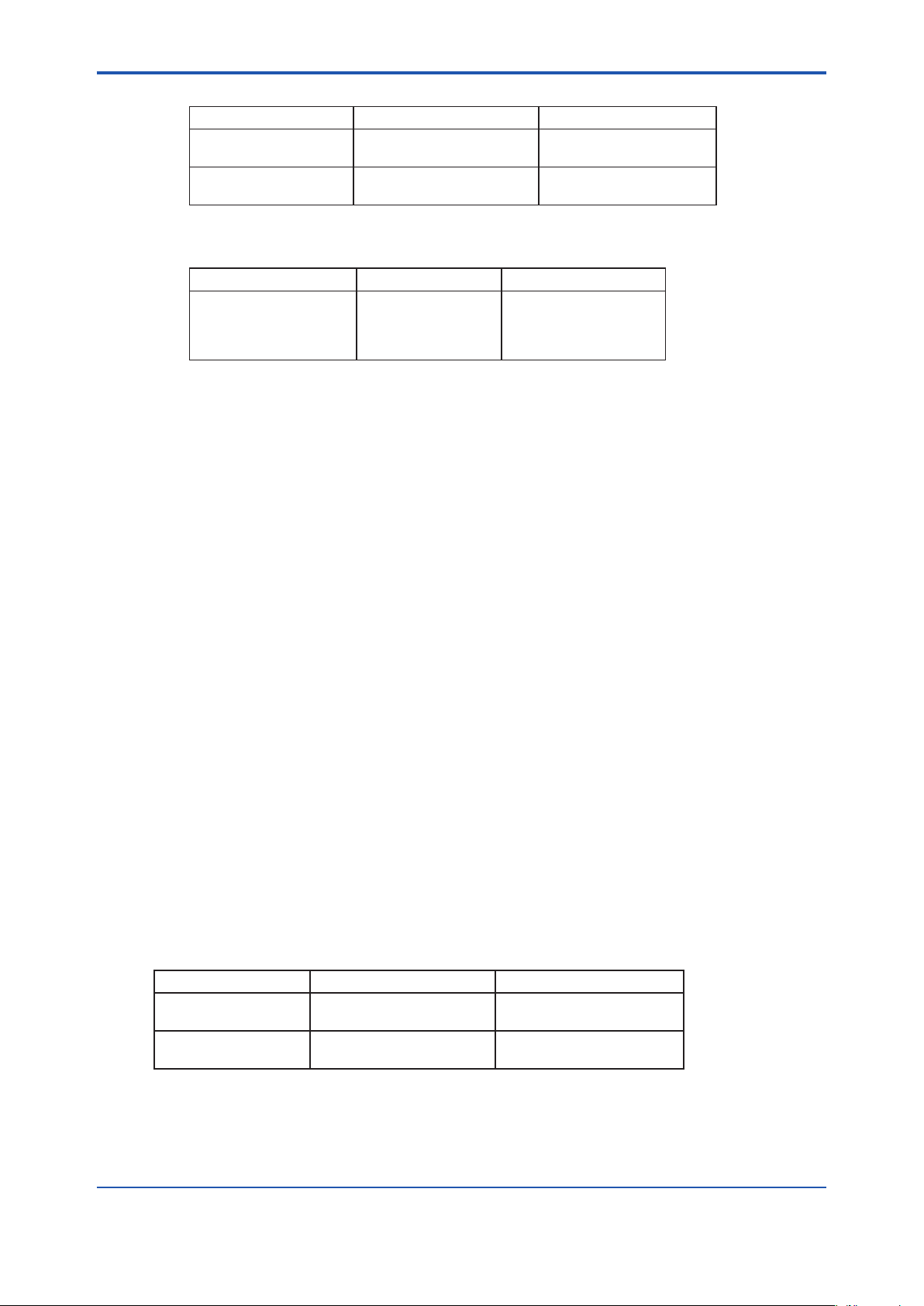
Repeatability
Measurement Measuring range (Note 1) Repeatability
WI
Caloric value
3
MJ/Nm
Note 1: High caloric value means 6.3 MJ/Nm3 or more. Low caloric value means below 6.3 MJ/Nm3.
High caloric value
Low caloric value
High caloric value
Low caloric value
± 0.5% of measured value
± 1.0% of measured value
± 1.0% of measured value
± 1.5% of measured value
Sample Gas Flow Rate : Approx. 10 l/min
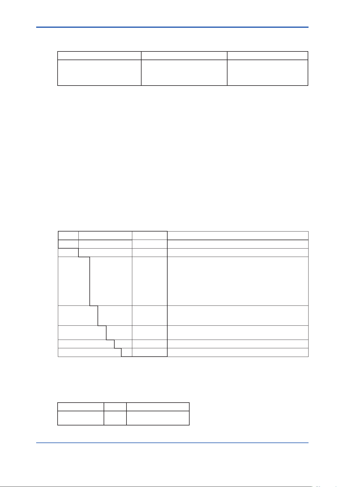
Response Time (Note 2):
Max.WImeasured Dead time Response time (63.2%)
50 or more
32 or more, less than 50
13 or more, less than 32
Less than 13
Note 2: Response time varies depending on the WI of a sample gas. This is due to the dierent sample gas ow rate of the
calorimeter. The ow rate is preset depending on the WI of the sample gas to prevent the caloric value at the detector
burner from exceeding the upper limit.
Approx. 30 sec or less
Approx. 27 sec or less
Approx. 23 sec or less
Approx. 21 sec or less
Approx. 60 sec or less
Approx. 53 sec or less
Approx. 47 sec or less
Approx. 41 sec or less
Utility :
Instrument Air ; Approx. 50 Nl/min, pressure 300 to 700 kPa, dew point of 0°C or less
Power Supply ; 100 V AC ± 10%, single phase, 50/60 Hz (Note 3), 860 VA max.
Note 3: When you perform a low caloric value measurement, the frequency variation should be within ±0.4%. If the frequency variation
exceeds ±0.4% (especially for exporting overseas), consult with Yokogawa.
1-2
n Steel Mill Application
Measurement Object : Measurement and control of WI or the caloric value of fuel gas for a
Measuring range : 3 to 62 MJ/Nm
Sample Conditions:
Dust; 100 mg/Nm
Temperature; 50°C or less
Pressure; (1) 8 to 15 kPa
(2) 8 kPa or under: with pump
Range : Select scale range (Span):
General Gas; 30 to 50% of maximum value of the span
Butane or Butene + Air; 20 to 30% of maximum value of the span
Propane or Propylene + Air; 25 to 40% of maximum value of the span
Output : 1 to 5 V DC, 4 to 20 mA DC (simultaneously), non-isolated, load
resistance 750Ω or less
Alarm Contact Output :
Flame o alarm;
Temperature alarm; 100 V AC, 3 A, closed when alarm occurs (resistance load)
Contact Input: Remote ignition (Custom order); 24 V DC, 0.1A or more
Repeatability :
Measurement Measuring range (Note 1) Repeatability
WI
Caloric value
3
MJ/Nm
steel mill.
High caloric value
Low caloric value
High caloric value
Low caloric value
3
3
or less
100 V AC, 5 A, closed when alarm occurs (resistance load) when
contact is opened, the leakage current is 2 mA or less (100V AC)
0.5% of measured value
1.0% of measured value
1.0% of measured value
1.5% of measured value
Note 1: High caloric value means 6.3 MJ/Nm3 or more. Low caloric value means below 6.3 MJ/Nm3.
IM 11R02A01-02E 6th Edition :May 10, 2019-00
Page 10
<1. Outline>
Sample Gas Flow Rate :Approx. 10 l/min.
Response Time (Note 2):
Max.WImeasured Dead time Response time (63.2%)
50 or more
32 or more, less than 50
13 or more, less than 32
Less than 13
Note 2: Response time varies depending on the WI of a sample gas. This is due to the dierent sample gas ow rate of the
calorimeter. The ow rate is preset depending on the WI of the sample gas to prevent the caloric value at the detector
burner from exceeding the upper unit.
42 sec or less
39 sec or less
36 sec or less
30 sec or less
70 sec or less
60 sec or less
50 sec or less
45 sec or less
Utility :
Water ; Approx. 0.2 l/min, pressure 200 to 600 kPa
Instrument Air ; Approx. 50 Nl/min, pressure 300 to 700 kPa, dew point of 0°C or less
Power Supply ; 100 V AC ± 10%, single phase, 50/60 Hz (Note 3), 1100 VA max.
Note 3: In case of low caloric value measurement, frequency variation should be within ± 0.4%. If frequency variation exceeds ± 0.4%,
consult with Yokogawa.
Panel:
Construction : For indoor installation, rack panel
Paint Color: Munsell 3.2PB7.4/1.2 (inside and outside)
Ambient Temperature:
0 to 40°C (little temperature variation,particularly no
rapid change )
1-3
1.2 ModelandSuxCodes
n CM6G Gas Calorimeter
Model SuxCode Option Code Description
CM6G
Gas
Pressure
Measurement 00
Power supply -5
Range R - - - - - - - - - - Measuring range
Style *C - - - - - - - - - - Style C
Note: Measuring range and unit must be specied.
- - - - - - - - - - - - - - - - -
-S6 - - - - - - - - - - Always - S6
1
2
3
4
5
6
7
8
10
-6
- - - - - - - - - - Gas calorimeter
- - - - - - - - - -
- - - - - - - - - -
- - - - - - - - - -
- - - - - - - - - -
- - - - - - - - - -
- - - - - - - - - -
- - - - - - - - - -
- - - - - - - - - -
- - - - - - - - - -
- - - - - - - - - -
- - - - - - - - - -
- - - - - - - - - -
Gas pressure 10 to 20 kPa for town gas, quake-proof
Gas pressure 10 to 20 kPa for town gas
Gas pressure 10 kPa or under for town gas
Gas pressure 100 ro 600 kPa for town gas
Gas pressure 8 to 15 kPa for steel mill, without preheating
Gas pressure 8 to 15 kPa for steel mill, with preheating
Gas pressure 8 kPa or under for steel mill, without preheating
Gas pressure 8 kPa or under for steel mill, with preheating
WI measurement
Caloric value measurement (GD400G should be purchased
separately)
100 V AC 50 Hz
100 V AC 60 Hz
l Standard Accessories
Followings are the standard accessories supplied.
• Calorie Detector
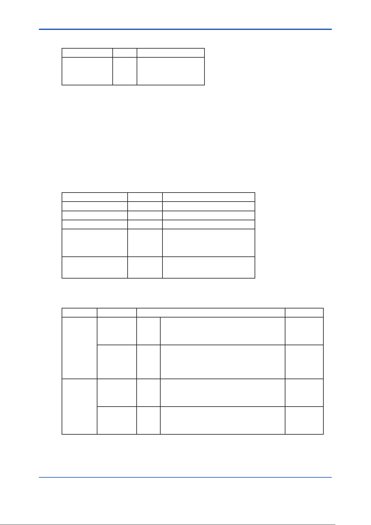
Name Q’ty Remarks
Mirror
Fuse
For burner ame inspection
1
2
3.15 A (A1113EF)
IM 11R02A01-02E 6th Edition :May 10, 2019-00
Page 11
<1. Outline>
• Orice Assembly
Name Q’ty Remarks
O-Ring
O-Ring
Hexagon Wrench
Hexagon Wrench
1
P16 (Viton) (Y9114XB)
3
P20 (Silicon) (L9817MT)
1
Nominal size 1.5 mm
1
Nominal size 2.5 mm
n Gas Density Meter
Gas Density Meter compensates a density value in caloric value measurement.
It is not required for WI measurement.
Converter: GD400G-N-10-N-/PA
Detector: GD300S-J-/KU
Measuring range and unit (specic gravity or density) should be specied. See GS 11T3E1-01E
for further information.
n Option
You must purchase options separately.
Name Part no. Description
Probe H7800HA Insertion length 650 mm
Probe H7800HB Insertion length 1150 mm
Probe H7800HC Insertion length 1650 mm
Fulo lter G7043XJ Element material: Polypropylene
Pressure reducing valve G7008XF Primary pressure: 15 MPa max.
Pore size: 50 μm
Body: SUS 316
Connection: Rc 1/2
Secondary pressure: 0 to 200 kPa
Material: Brass
1-4
1.3 Standard Systems for Each Application
Application Measurement Systemspecication Suxcode*
WI
Town Gas
Caloric value
3
MJ/Nm
WI
Steel Mill
Caloric value
3
MJ/Nm
* The code is basic for gas pressure and measurement.
Note: A wet sample gas in the town gas application is outside the scope of the standard specications. Consult
with Yokogawa.
Without
density
meter
With
density
meter
Without
density
meter
With
density
meter
Gas pressure 10 to 20 kPa: Standard
Gas pressure 10 kPa or under: With pump
Gas pressure 100 to 600 kPa: With pressure
reducing value
Gas pressure 10 to 20 kPa: Quake-proof
Gas pressure 10 to 20 kPa: Standard
Gas pressure 10 kPa or under: With pump
Gas pressure 100 to 600 kPa: With pressure
reducing value
Gas pressure 8 to 15 kPa: Without preheating
Gas pressure 8 to 15 kPa: With preheating
Gas pressure 8 kPa or under: Without preheating
Gas pressure 8 kPa or under: With preheating
Gas pressure 8 to 15 kPa: Without preheating
Gas pressure 8 to 15 kPa: With preheating
Gas pressure 8 kPa or under: Without preheating
Gas pressure 8 kPa or under: With preheating
-S6200
-S6300
-S6400
-S6110
-S6210
-S6310
-S6410
-S6500
-S6600
-S6700
-S6800
-S6510
-S6610
-S6710
-S6810
IM 11R02A01-02E 6th Edition :May 10, 2019-00
Page 12

<1. Outline>
n Instructions for System Selection
● The quake-proof type gas calorimeter is always equipped with the density meter.
● The CM6G Gas Calorimeter controls the ow rate under a constant dierential pressure. In
the caloric value measurement, if the density of a sample gas changes, a ow rate error
proportional to the reciprocal of the square root of the density of the sample gas,
will be generated, which directly aects the caloric value. Therefore, density compensation
is required using a density meter.
For the WI measurement, a density meter is not required since the WI is a value
proportional to
ρ
.
g
1/
1-5
ρ
g
1/
,
IM 11R02A01-02E 6th Edition :May 10, 2019-00
Page 13
<1. Outline>
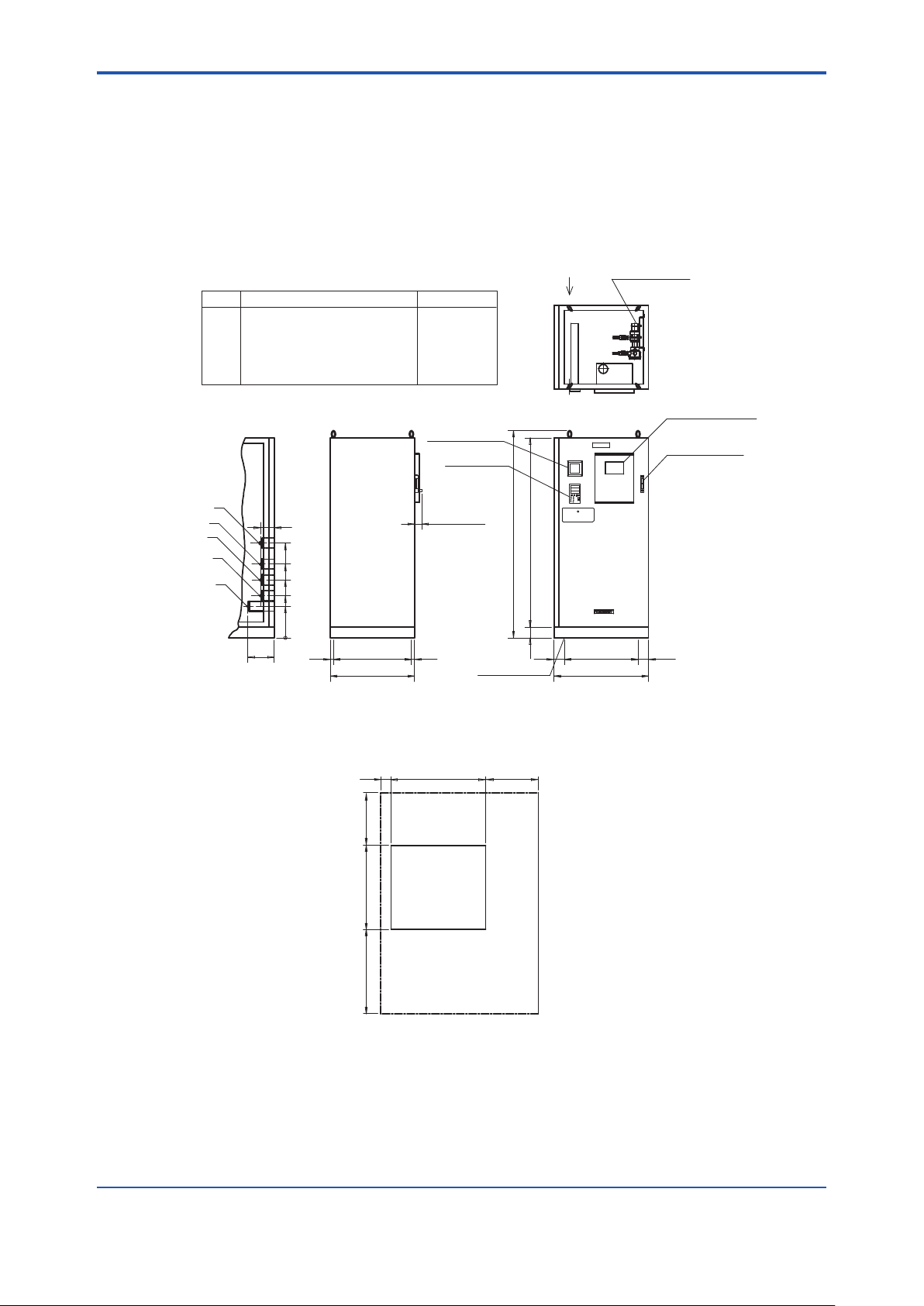
1.4 ExternalDimensions
n For Town Gas Applications
CM6G-S6200, S6210, S6300, S6310, S6400, S6410
1-6
Unit: mm
Mark Name Connection
A SAMPLE GAS IN Rc1/4
SAMPLE GAS OUT
B
C INST.AIR IN Rc1/4
D STD.GAS IN Rc1/4
E STD.GAS IN Rc1/4
B
D
E
A
C
250
View X
130
900
700
550
400
300
0
OR VENT Rc1/2
30
740
800
Density meter
converter
Computing
station
Approx.70
30
*
1800100
Approx.1970
100
4-Ø14 holes
X
* CM6G-S610 (with density meter) only
Density meter
detector
700
900
*
Calorie detector
Flowmeter for
density meter
100
*
Maintenance Space
100
800800 500
900
Back
Front
500
Weight: Approx. 300kg
Dim-6210.ai
IM 11R02A01-02E 6th Edition :May 10, 2019-00
Page 14
<1. Outline>
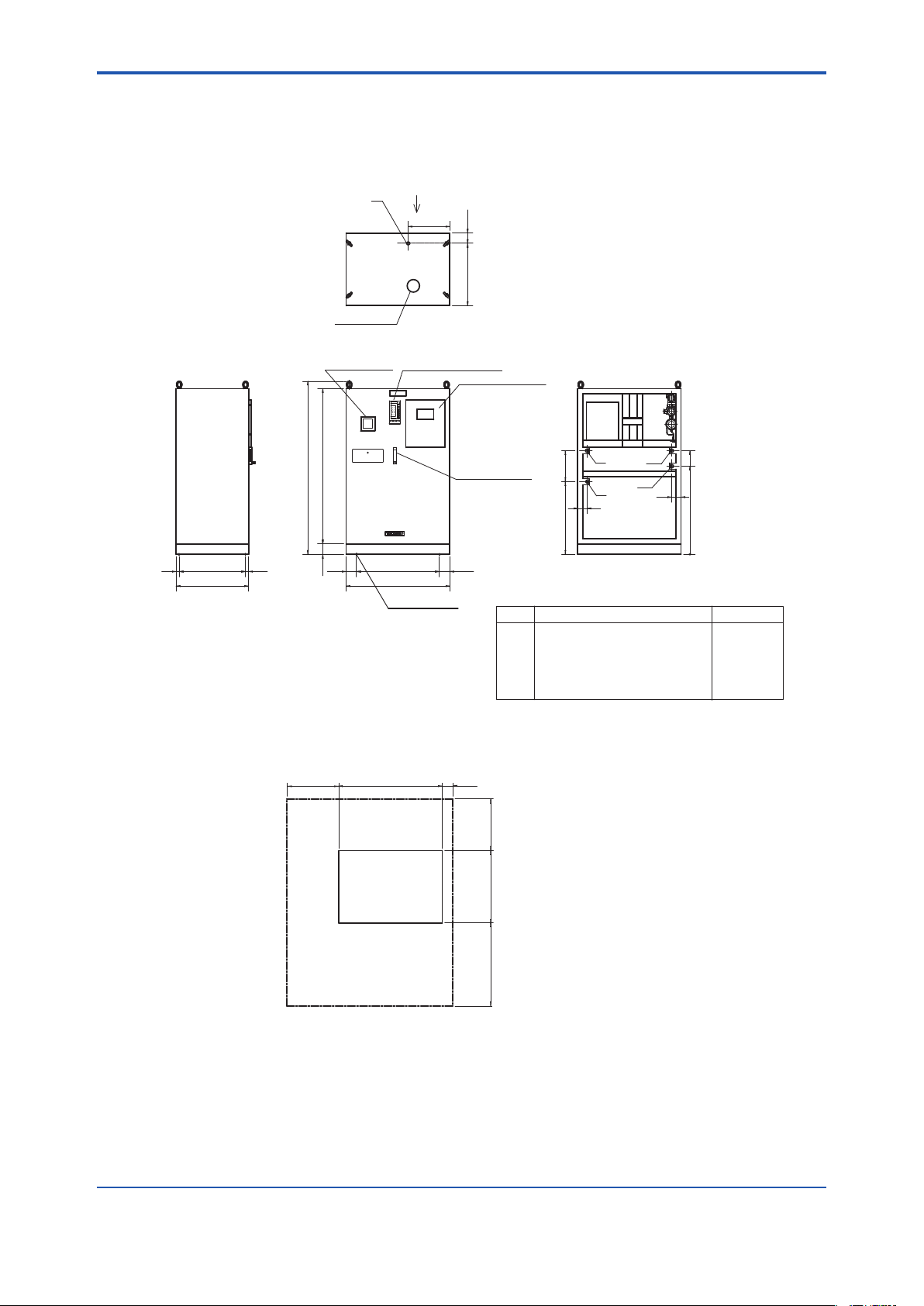
n For Town Gas Application (Quake-proof Type)
CM6G-S6110
1-7
30 640 30
700
Ø120 hole
Density meter
converter
1500100
Approx. 1670
X
D
400
Computing station
FAIL
---CM6G---
ALM
TREND 3
90.00
18.00
Y2Y1X3X1500.0
35.00
C
1000.0
37.67
100.00
23.02
A
M
▼▼▼
△
▽
PF
0.00
14.65
0.0
23.02
▼
C
O
SHIFT
<
<<<
YOKOGAWA◇
1000
4-Ø15 holes
100600
Calorie detector
Flowmeter for
density meter
100800100
300700
90
A
B
C2
View X
C1
90
Mark Name Connection
A SAMPLE GAS IN Rc1/4
B INST.AIR IN Rc1/4
C1 STD.GAS IN (ZERO) Rc1/4
C2 STD.GAS IN (SPAN) Rc1/4
D SAMPLE GAS OUT OR VENT Rc1/2
Wiring to switch box should be made
through the bottom.
Unit: mm
1000
850
0
Maintenance Space
1000 100500
Back
Front
500
700
800
Weight: Approx. 350kg
Dim-6110.ai
IM 11R02A01-02E 6th Edition :May 10, 2019-00
Page 15
<1. Outline>
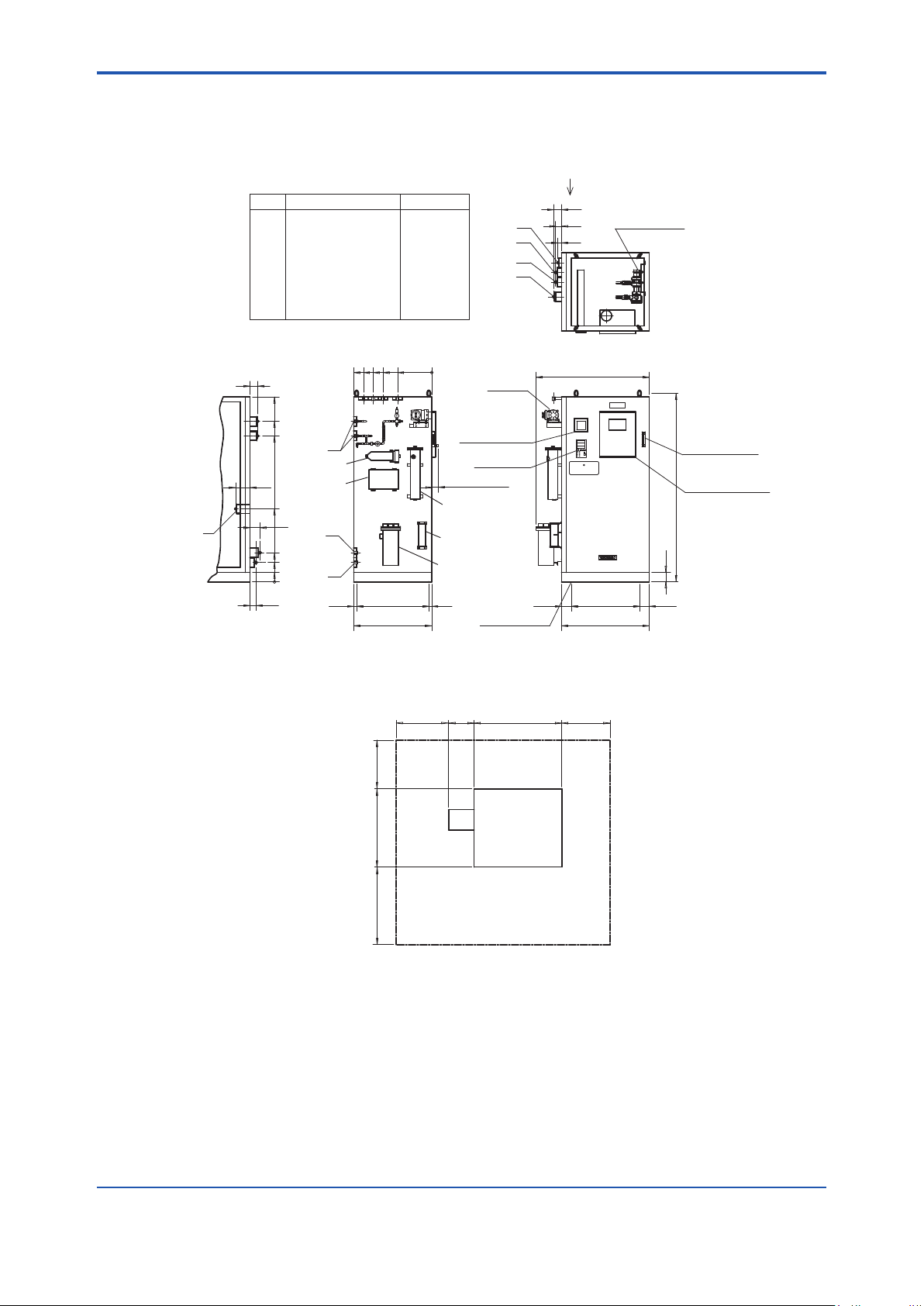
n For Steel Mill Application
CM6G-S6500, S6510, S6600, S6610, S6700, S6710, S6800, S6810
1-8
*
Flowmeter for
density meter
Calorie detector
Approx.1970
100
Unit: mm
*
X
Mark Name Connection
A SAMPLE GAS IN Rc1/2
B SAMPLE GAS OUT Rc1/2
C SAMPLE GAS OUT Rc1/2
D STD.GAS IN Rc1/4
E WATER IN Rc1/2
F DRAIN OUT Rc1/2
G INST.AIR IN Rc1/4
H SAMPLE GAS VENT Rc1/4
500
600
700
800
80
1900
1650
1500
150
750
View X
60
100
300
200
100
0
G
D
Fulflo filter
Dehumidifier
E
F
740 30(30)
800
0
350
Washing bubbler
Drain pot
Pressure regulating
pot
Density meter
converter
Approx. 70
H
B
C
A
**
Pump
*
Computing
station
4-Φ14 holes
80
60
40
Approx.1160
(100)
* CM6G-S610 (with density meter and flowmeter)
** CM6G-S670, CM6G-S680 (with pump)
Density meter
detector
700
900
100
500
800
800
Maintenance Space
540
900260
Back
Front
500
Weight: Approx. 350kg
Dim-6810.ai
IM 11R02A01-02E 6th Edition :May 10, 2019-00
Page 16
<1. Outline>
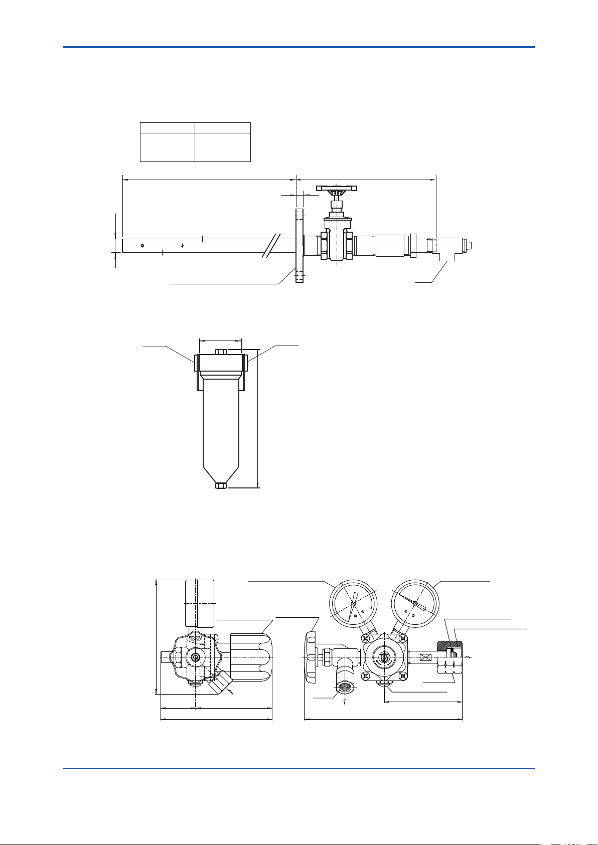
n Dimensions of Options
l Probe
Unit: mm
Part number L
H7800HA Approx. 650
H7800HB Approx. 1150
H7800HC Approx. 1650
)( 350Insertion length L
18
Φ34
1-9
JIS 10K-80-FF Equiv. SUS304
l FuloFilter(Partno.:G7043XJ)
108
Rc1/2Rc1/2
Approx. 350
Unit: mm
l PressureReducingValve(Partno.:G7008XF)
Secondary pressure
gauge
0.3MPaG
Rc1
Primary pressure
gauge
25MPaG
H7800HA.ai
Unit: mm
Approx. 119
Approx. 38
Handle for
pressure control
Approx. 62
Approx. 120
Outlet
Handle for
stop valve
Stop valve
Rc1/4
Outlet
H
C
I
A
H
K
O
A
T
開
閉
Safety valve
Approx. 166
Daiflon packing
W22 Left-hand thread
Inlet
Nut
Approx. 81
F2-8.ai
IM 11R02A01-02E 6th Edition :May 10, 2019-00
Page 17
<1. Outline>
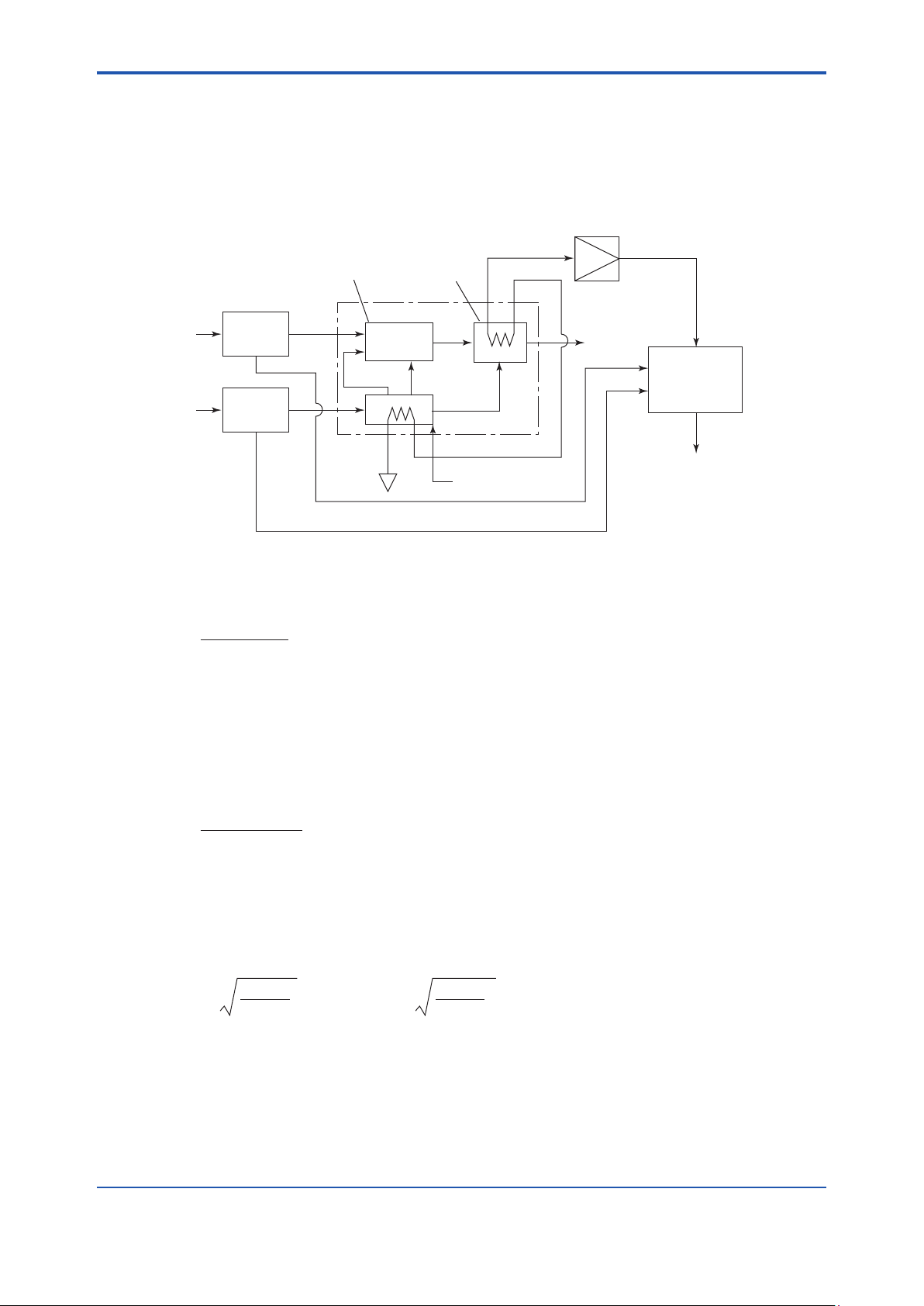
1.5 Principle of Measurements
The instrument detects the temperature dierence, using a thermocouple, between the exhaust
combustion gas made after sample gas is burnt in the burner, and the feed air at the inlet of
the burner. Then the instrument amplies the value of temperature dierence. It adds the
compensating calculation to the output signal and measures the caloric value of WI.
1-10
DIFFERENTIAL
PRESSURE
DETECTION
GAS
AIR
Figure 1.1 Measurement principle diagram
BURNING
PRIMARY
MIXING
SECONDARY
TERTIARY
AIR
DIVIDING
BLOW
COMPENSATING
CALCULATION
OUTPUT
SIGNAL
When the sample gas is completely burnt by the air, the formula of the increased temperature is
as follows:
∆θ = (1.1)
K • Fg
Cps • Fs
where K: Caloric value of the sample gas
Fg: Flow rate of the sample gas
Fs: Air-diluted combustion exhaust gas ow rate
Cps: Constant pressure heat ratio of air-diluted combustion exhaust gas
Air ow rate Fa is big enough compared with the sample gas ow rate Fg (Fa:Fg=50-200:1)
and Cps Cpa, Fs Fa+Fg=Fa ( 1 + g ), therefore, the formula (1.1) is as follows:
∆θ = (1.2)
K • Fg
Cpa • Fa (1 + g)
where Fa: Air ow rate
Cpa: Air constant pressure heat ratio
g: Fg/Fa
When using orice and take out Fa, Fg as a dierential pressure of before and after orice, Fa
and Fg are represented by the following formula:
Fa = Ka (1.3)
∆ Pa
ρ
a
Fg = Kg
∆ Pg
ρ
g
where: ∆Pa, ∆Pg: Air, gas dierential pressure between before and after orice
ρ
a, ρg: Density of the air and the gas
ka, kg: Orice constant gure of the air and the gas
(Orice coecient orice sectional area)
IM 11R02A01-02E 6th Edition :May 10, 2019-00
Page 18

<1. Outline>
If insert formula (1.3) into formula (1.2), ∆θ is represented by the following formula:
1-11
∆θ = C.K. (1.4)
1
ρ
•
g
(C =
∆ Pg
∆ Pa
1
Cpa (1+g)
Kg
• • )
Ka
ρ
a
According to formula (1.4), if ∆Pa, ∆Pg are constant, temperature dierence ∆θ is in proportion
ρ
g
to WI (
K/
) or caloric value (K). Thus we can measure continuously WI after ∆θ
measurement, and the caloric value after the measurement and calculation of the density.
IM 11R02A01-02E 6th Edition :May 10, 2019-00
Page 19

Blank Page
Page 20
<2. Installation, Piping, Wiring>
2. Installation, Piping, Wiring
2.1 Installations
Observe the following conditions when you install instruments.
(1) Adequate space for maintenance should be provided around the gas calorimeter.
* See “External Dimention” on 1.4.
(2) The base should be horizontal..
(3) Ambient temperature is 0 to 40°C and no rapid change in ambient temperature is allowed.
*Rapid change here means a change of approximately 10°C within 30 minutes.
(4) Install the instrument in the place where it is not directly exposed to the current of a
conditioned air.
(5) Minimal vibration( If much vibration is unavoidable, take an appropriate measure to absorb
shock, e.g, use of vibration-proof robber).
(6) A ventilation system should be provided.
(7) Corrosive gases and dust are present in small quantities and humidity is low.
(8) The water of the sampling system and the drain line do not freeze up.
2-1
WARNING
From the moment the ignition starts until it completes, or right after the ame extinction, sample
gas mixed with the air will be released from the top of the equipment into the installation space of
the equipment. Use the equipment in a well ventilated environment equipped with a ventilation
system.
2.2 Externalpiping
Refer to the drawing Figure 1.4. on the connections on the panel
The principal points to be taken care are as follows:
• Bent the outlet of the bent piping as U shape, and prevent it from the rain penetration. Set
the outlet at higher position as much as possible where there is little fear of physical danger.
• Drain piping shall be conducted below the level of drain outlet on the panel and conrm no
drain is accumulated on the panel bed.
• It is necessary for the sample line of the instrument for steel mill use to provide a slope of
more than 1/3, so that there is no blockade to the gas line by the drain at the bending part of
the piping. Make piping as short as possible. Equip the sample line with thermal insulation
so as to prevent the drain in the pipe line from freezing.
• Locate the standard gas cylinders at the place where they are comparatively cool and not
exposed to direct sunshine.
IM 11R02A01-02E 5th Edition : Dec. 28, 2016-00
Page 21

<2. Installation, Piping, Wiring>
Probe
Sampling Point
Steam for thermal
insulation
Water In
Vent to the
atmosphere
Drain
Safely vent to the atmosphere
Filter
Filter
Tetoron Braid
Hose
Pipe Φ6/Φ4 Cu
Pipe Φ6/Φ4 Cu
Zero Gas
Span Gas
Valves for maintenance
should be installed.
Pipe SUS 15A
Sample Gas Inlet
Std. Gas
Inlet
Pressure
Reducing
Valve
Wash water inlet
Pipe SUS 15A
Pressure:0.1-0.2MPa
Sample Gas Out
CM6G
Gas
Calorimeter
Pipe SUS 15A or greater
Sample Gas Vent
Sample Gas Out
Pipe SUS 15A
Drain Outlet
Pipe SUS 15A
Steam for
blowing back
Pipe SUS 15A
Pressure
Reducing
Valve
∆H
∆H: Water sealing greater than pressure at sampling point is required.
Seal pot
Note: denotes that piping should be installed at an angle that allows drain to flow downstream and smoothly. F4-1.ai
House Requirements
Temperature: 0 to 40˚C
Not rapid temperature change allowed.
Adequate ventilation and lighting provided.
Power Supply
100 V AC±10% 50/60Hz
Max. approx.1100 VA
Output Signal
Alarm Contact
Output Signal
Instrument Air
Pressure: 0.3-0.7MPa
Flow rate: Approx. 50Nl/min
Figure 2.1 Recommended Sampling for Steel Mill Use
2-2
Drain
• Sampling point shall be made at the location above or side of the transfer pipe. When the
instrument is mounted on wall, x it with a slope that the top end of the probe is facing
downward.
• When xing the probe, use a ange JIS 10K 80A.
• At the sample gas outlet of the probe, it is recommended to provide a gate valve of 1/2 inch.
Probe
Gate valve (1/2 inch)
Flange
100 or more
Figure 2.2 Mounting of the Probe
Transfer pipe
F4-2.ai
IM 11R02A01-02E 5th Edition : Dec. 28, 2016-00
Page 22

<2. Installation, Piping, Wiring>
• Fix lter vertically with their drain outlets facing downward. Mount it rmly to wall or to pillar
with U bolt-like bolts. Provide 1/2 inch gate valves at the sample gas inlet and outlet. Take an
ample space under lters so that checking and replacing of elements can be held easily. For
drain exhaust pipes, use exible pipes.
Gate valve (1/2 inch)
2-3
Rc1/2
Out
Fulflo filter
Bush
Flexible tube
Drain
Rc1/4
Drain
Figure2.3ExampleFuloFilterswiththePiping
In
Union (1/2 inch)
U-bolt
F4-3.ai
IM 11R02A01-02E 5th Edition : Dec. 28, 2016-00
Page 23

<2. Installation, Piping, Wiring>
2.3 ExternalWirings
External wires shall be connected from the terminal block of the switch box inside the
panel. Use M4 terminal screws. Use appropriate crimp terminals at the wire ends.
MAIN PANEL
DENSITY METER
CONVERTER
COMPUTING
STATION
SWITCH BOX
350
CALORIE
DETECTOR
2-4
200
Figure 2.4 SwitchBoxandEarth
SWITCH
NFB
POWER
TERMINAL
150
EARTH TERMINAL
SIGNAL TERMINAL
810
Figure 2.5 InsideaSwitchBox
FUSE
IM 11R02A01-02E 5th Edition : Dec. 28, 2016-00
Page 24

<2. Installation, Piping, Wiring>
n Notes on Wiring
• Turn o all power supplies while connecting cables and wires.
• An electrical wiring duct must not be used for the simultaneous connection of a large
capacity converter, motor, or power supply.
• When cables are connected in a place with high or low ambient temperatures, use cables
suitable for the place.
• The material of cables must be capable of withstanding harmful gases, lizids, oil , or
solvents when cables are used in the atmosphere where these harmful substances are
present.
• Use crimp terminals with insulated sleeve (M4 screws) for the wire ends.
n Wiring to Peripheral Equipment
l Power Supply
Use a 600 V insulated vinyl cabtyre cable (JIS C3312) with a cross-section area of 2 mm2 or
more, or a wire or cable that is the equivalent or better.
l Grounding
Connect a grounding wire to the grounding terminal inside the panel. A grounding wire must be
connected so that the grounding resistance becomes 100 Ω or less (equivalent to JIS Class D).
2-5
l Analog Output (4 to 20 mA DC)
Use a shielded twisted pair cable with a cross-section area of 0.5 mm2 or more, or a cable that is
the equivalent or better, and install it separately from the power supply and alarm output cables
and sources of electromagnetic interference. A shielded cable must be connected to the frame
ground (FG) beside each of the output terminals. The load resistance from the perspective of this
equipment must be 750 Ω or less.
l Contact Output
Use a 600 V insulated vinyl cabtyre cable (JIS C3312) with a cross-section area of 2 mm2 or
more, or a wire or cable that is the equivalent or better.
The ame extinction alarm contact and orice chamber temperature drop alarm contact must be
non-voltage dry contacts and the contact rating must be as follows.(when contact is opened, the
leakage current is 2 mA or less (100V AC))
Contact Rating
Flame distinction alarm contact 100 V AC 5 A
Orice chamber temperature drop alarm contact 100 V AC 3 A
l Contact Input (Remote Ignition: Made to order)
Input a non-voltage contact as a contact input signal. The contact rating is 24 V DC 1 A. The
open or closed state of the input is determined by the resistance value from the perspective of
this equipment. The resistance value also includes the wiring resistance.
Contact closed: 200 Ω or less.
Contact open: 100 kΩ or more.
IM 11R02A01-02E 5th Edition : Dec. 28, 2016-00
Page 25

<2. Installation, Piping, Wiring>
2-6
IM 11R02A01-02E 5th Edition : Dec. 28, 2016-00
Page 26

<3.Construction and Function>
F00.ai
3. Construction and Function
TypicalSystemConguration
Gas Calorimeter
Calorie Detector
Solenoid
Valve
Computing Station
---CM6G---
TREND 3
18.00
Y2Y1X3X1500.0
35.00
1000.0
100.00
0.00
0.0
▼
C
<<<
YOKOGAWA◇
Differential
Pressure
Transmitter
Orifice Assembly
FAIL
ALM
90.00
C
37.67
23.02
A
M
▼▼▼
△
▽
PF
14.65
23.02
O
SHIFT
<
Output
4-20mA DC
1 to 5V DC
Density Meter
Gas
Pressure
Regulating
Unit
Air
Pressure
Regulating
Unit
P
Calorific Value
WI (Wobbe Index)
Sample Gas
Instrument Air
3-1
Item Function / Description
Calorie detector
Detects WI or caloric value. Generates an alarm and takes protective
actions when the burner ame goes out or abnormal combustion occurs.
Computing station (digital) Calculates WI or caloric value. Displays selected parameters, e.g., each
dierential pressure and caloric value. Adjusts zero / span and others.
Density meter Measures density used for calculation of caloric value. Not required for
WI measurement.
Dierential pressure transmitter Detects dierential pressure of gas and air before and after orice, and
converts it to an electrical signal.
Orice assembly Gas and air orices housed in the constant temperature chamber.
Solenoid valve Serves as a safety valve to shut o the sample gas ow.
Figure 3.1 Components and Functions of Model CM6G Gas Calorimeter
3.1 Air Pressure Regulating System
Refer to Figure 3.2, 3.3 and 3.4. The instrument air pressure (300 to 700 kPa) is reduced by air
set (2-1) to about 200 kPa, further reduced to about 20 kPa by the pressure reducing valve (2-2).
Then the pressure is set by needle valve (V-16) to a dierential pressure of 500 Pa.
The air is controlled at 40°C in the preheater, which helps the temperature control by the orice.
When the temperature rises above 60°C, thermostat in the preheater operates and intercepts the
power supply of the heater. This air pressure regulating section is common to all systems.
3.2 Gas Pressure Control Section
Refer to Figure 3.2, 3.3 and 3.4.The gas pressure regulating section has two dierent types; town
gas use and steel mill use.
IM 11R02A01-02E 5th Edition : Dec. 28, 2016-00
Page 27

<3.Construction and Function>
l Town Gas Use
The sample gas, introduced through line lter (3-1), increases its pressure by pump, or
decreases by pressure reducing valves, according to the pressure at the sampling point. The
pressure gauge (3-2) indicates 8 to 18 kPa and the owmeter (3-3) approx. 10 l/min, respectively.
The sample gas, then, is set its dierential pressure to 500 Pa by pressure reducing valve (3-4)
and (3-6), and at this time the pressure gauge (3-5) indicates approx. 3 kPa. When the density
compensation system is equipped, the sample gas is introduced to the density meter with the ow
rate of 1 l/min, through the owmeter (5-3).
The standard gas is reduced its pressure to 8 to 18 kPa by the pressure reducing valve (4-1), and
supplied, same as the sample gas, with the ow rate approx. 10 l/min.
l Steel Mill Use
The pressure of the sample gas is increased, by the pump, according to that of the sampling
point.
The pressure gauge (3-1) indicates approx. 6 kPa. The sample gas then ows through the
washing bubbler (3-2) and the fulo lter (3-3), and then secure a constant pressure in the
pressure regulating pot (3-4) through the water sealed pipe from the dehumidier (3-5), then set
the dierential pressure by the pressure reducing valve (3-6) to 500 Pa.
To increase the pressure by the pump, a drain pot (3-9) is added. When the density
compensation system is equipped, the sample gas is supplied to the density meter with its ow
rate of 1 l/min, through the owmeter (5-3). The pressure of the standard gas is reduced by the
pressure reducing valve (4-1) to about 6 kPa and is supplied by the owmeter (4-2) with the ow
rate about 10 l/min.
3-2
Standard Flow Sheet
1. Town Gas Application (Standard Type)
CM6G-S6200, S6210, S6300, S6310, S6400, S6410
No. Item
1-1 Calorie detector
1-2 Solenoid valve
1-3 Orifice assembly
1-4 Differential pressure transmitter (air)
1-5 Differential pressure transmitter (gas)
1-6 Computing station
2-1 Air set
2-2 Pressure reducing valve
2-3 Pressure gauge
2-4 Preheating chamber
2-5 One touch coupler
V-1
V-2
SAMPLE GAS IN
SAMPLE GAS OUT
OR VENT
Maximum back pressure
is 1.5 kPa and no pressure
fluctuation is allowed.
A
B
No. Item
3-1 Line filter
3-2 Pressure gauge
3-3 Flowmeter
3-4 Pressure reducing valve
3-5 Pressure gauge
3-6 Pressure reducing valve
3-7 Diaphragm pump (when specified)
3-8 Pressure reducing valve (when specified)
4-1 Pressure reducing valve for standard gas
*3
3-8
V-4
3-1
*1
*2
3-7
V-5
V-3
P
DT
5-1
5-2
*1: CM6G-S610 (with density meter)
*2: CM6G-S630 (with diaphragm pump)
*3: CM6G-S640 (with pressure reducing valve)
V-11
V-6
V-13
5-3
V-7
3-2
3-3
3-4
3-6
3-5
V-12
GAS
DP.T
1-1
1-2
No. Item
5-1 Density meter detector (when specified)
5-2 Density meter converter (when specified)
5-3 Flowmeter for density meter (when specified)
6-1 Zero gas (supplied by customer)
6-2 Span gas (supplied by customer)
7-1 Pressure reducing valve for cylinder (optional)
7-2 Pressure reducing valve for cylinder (optional)
V1...16 Ball valve, needle valve
1-6
1-3
AIR
DP.T
1-5
1-4
V-16
4-1
2-4
2-3
V-15
2-1
V-14
2-2
2-5
V-9
V-8
V-10
FLOW-6410.ai
INST.AIR IN
0.3~0.7MPa
C
50Nl/min
STD GAS IN (ZERO)
7-1
7-2
D
E
6-2
STD GAS IN (SPAN)
6-1
Figure 3.2 Flow Sheet (for Town Gas)
IM 11R02A01-02E 5th Edition : Dec. 28, 2016-00
Page 28

<3.Construction and Function>
2. Town Gas Application (Quake-proof Type)
CM6G-S6110
No. Item
1-1 Calorie detector
1-2 Solenoid valve
1-3 Orifice assembly
1-4 Differential pressure transmitter (air)
1-5 Differential pressure transmitter (gas)
1-6 Computing station
2-1 Air set
2-2 Pressure reducing valve
2-3 Pressure gauge
2-4 Preheating chamber
2-5 One touch coupler
No. Item
3-1 Line filter
3-2 Pressure gauge
3-3 Flowmeter
3-4 Pressure reducing valve
3-5 Pressure gauge
3-6 Pressure reducing valve
4-1 Pressure reducing valve
5-1 Density meter detector
5-2 Density meter converter
5-3 Flowmeter for density meter
No. Item
6-1 Zero gas (supplied by customer)
6-2 Span gas (supplied by customer)
7-1 Pressure reducing valve for cylinder (optional)
7-2 Pressure reducing valve for cylinder (optional)
V1...16 Ball valve, needle valve
3-3
V-4
V-1
V-2
SAMPLE GAS IN
(10 to 20kPa)
SAMPLE GAS OUT
OR VENT
Maximum back pressure
is 1.5 kPa and no pressure
fluctuation is allowed.
A
D
V-3
3-1
5-1
5-2
Figure 3.3 Flow Sheet (for Town Gas)
1-5
1-3
AIR
DP.T
1-4
1-6
V-16
4-1
2-4
2-2
2-3
V-15
2-5
V-8
2-1
V-14
V-9
V-10
FLOW-6110.ai
INST.AIR IN
0.3 to 0.7MPa
B
50Nl/min
STD GAS IN (ZERO)
7-1
7-2
C1
C2
STD GAS IN (SPAN)
6-1
6-2
1-1
3-3
3-4
3-6
3-5
V-12
GAS
DP.T
1-2
3-2
V-11
V-5
V-6
V-7
V-13
P
5-3
DT
IM 11R02A01-02E 5th Edition : Dec. 28, 2016-00
Page 29

<3.Construction and Function>
3. Steel Mill Application
CM6G-S6500, S6510, S6600, S6610, S6700, S6710, S6800, S6810
No. Item
1-1 Calorie detector
1-2 Solenoid valve
1-3 Orifice assembly
1-4 Differential pressure transmitter (air)
1-5 Differential pressure transmitter (gas)
1-6 Computing station
2-1 Air set
2-2 Pressure reducing valve
2-3 Pressure gauge
2-4 Preheating chamber
2-5 One touch coupler
No. Item
3-1 Pressure gauge
3-2 Washing bubbler
3-3 Fulflo filter
3-4 Pressure regulating pot
3-5 Dehumidifier
3-6 Pressure reducing valve
3-7 Line filter
3-8 Diaphragm pump (when specified)
3-9 Drain pot (when specified)
4-1 Pressure reducing valve for cylinder
4-2 Flowmeter
No. Item
5-1 Density meter detector (when specified)
5-2 Density meter converter (when specified)
5-3 Flowmeter for density meter (when specified)
6-1 Water Flowmeter
7-1 Probe (optional)
7-2 Fulflo filter (optional)
9-1 Pressure reducing valve for cylinder (optional)
9-2 Pressure reducing valve for cylinder (optional)
10-1 Standard gas cylinder (supplied by customer)
10-2 Standard gas cylinder (supplied by customer)
11-1 Drain pot (supplied by customer)
V1...16 Ball valve, needle valve
3-4
WATER IN
DRAIN
9-1
9-2
7-1
10-2
SAMPLE GAS IN
11-1
STD.GAS IN
(SPAN)
STD.GAS IN
10-1
7-2
WATER IN
DRAIN OUT
(ZERO)
SAMPLE GAS
OUT
2-5
B
*1
*2
4-1
V-9
D
V-10
D
A
V-1
3-9
E
F
V-8
3-1
V-3
3-2
V-13
V-4
P
V-6
V-5
6-2
3-8
V-2
V-7
*1: CM6G-S610 (with density meter)
*2: CM6G-S670, CM6G-S680 (with diaphragm pump)
SAMPLE GAS VENT
SAMPLE GAS OUT
H
C
4-2
V-11
V-12
3-3
*1
5-3
3-6
3-7
3-5
3-4
1-2
5-1
5-2
1-1
1-5
1-3
V-16
1-4
2-4
2-2
P
1-6
V-15
2-3
2-1
V-14
INST.AIR IN
G
FLOW-6810.ai
Figure 3.4 Flow Sheet (Steel Mill Use)
3.3 DierentialPressureDetectionPart
In order to calculate the dierential pressure correction value, the ow rate is acquired from
the orice as a dierential pressure and converted to an electrical signal using the dierential
pressure transmitter. The orice is housed in a constant temperature chamber (orice assembly),
the temperature of which is maintained at approximately 50°C by the temperature controller, to
prevent the temperature drift of the actual ow rate.
When the temperature exceeds 90°C, the safety thermostat is activated to shut o the heater
power supply. When the temperature falls after the power supply is shut o, the alarm thermostat
is activated to provide an alarm (closed contact) output.
CAUTION
Power is supplied to the dierential pressure transmitter and the temperature controller from the
calorie detector. To operate the transmitter and the controller, turn on the calorie detector switch
of the switch box and the POWER switch on the front panel of the calorie detector.
IM 11R02A01-02E 5th Edition : Dec. 28, 2016-00
Page 30

<3.Construction and Function>
MAIN PANEL
ORIFICE ASSEMBLY
DIFFERENTIAL PRESSURE
TEMPERATURE
CONTROLLER
TRANSMITTER
Figure3.5DierentialPressureDetectionEquipment
3-5
3
9
4
19
16
15
8
10
18
No. Name
Air inlet
1
Gas inlet
2
Air outlet
3
Gas outlet
4
Air differential pressure take-out
5
Gas differential pressure take-out
6
Orifice section
7
No. Name
8
9
10
11
12
13
14
Figure3.6OriceAssembly
3.4 Calorie Detector
The calorie detector consists of a burner unit, which detects the temperature dierence before
and after the sample gas is burned, a detected signal amplication and ignition-and safety
sequence circuit, and distributor circuits of the transmitter for air and the transmitter for gas.
The detected signal is converted from approximately 0 - 20 mV to 1 - 5 V DC and input to the
computing station. If burner ame extinction or excessive combustion occurs, an alarm (closed
contact) output is produced.
7
12
11
Gas orifice section
Crotchet joint
Fitting screw
Heat conversion block
Heater plate
Safety thermostat (up)
Alarm thermostat (down)
13·14
5
6
2
17
No.
Thermistor (check)
15
Thermistor (control)
16
Temperature check terminal
17
Neon lamp
18
Terminal
19
1
Name
F0506.ai
IM 11R02A01-02E 5th Edition : Dec. 28, 2016-00
Page 31

<3.Construction and Function>
PRINTED CIRCUIT
BOARD ASSEMBLY
BURNER UNIT
IGNITION TRANS.
ASSEMBLY
Figure 3.7 Calorie Detector
3-6
POWER
Lamp
IGNIT
Lamp
0
Figure 3.8 Front Panel Assembly
SAFE EV
Switch
LOW AL
Volume
MEAS
Lamp
ALARM
Lamp
START
Switch
POWER
Switch
METER
Switch
SPAN
Volume
IM 11R02A01-02E 5th Edition : Dec. 28, 2016-00
Page 32

<3.Construction and Function>
Table 3.1 Function and operation procedure for each switch of the calorie detector
Name Function and operation procedures
“POWER” switch • Power supply switch.
• When the switch turns to “ON”, the power is supplied to the calorie detector and at the
same time the lamps, “POWER” and “ALARM” are lit on.
“START” switch • One push on “START” switch introduces gas to the burner unit and operates the ignition.
• At the same time, the lamp “IGNIT” is on while the lamp “ALARM” is lit o.
• If ignition occurs within the preset time, the lamp “IGNIT” is lit o but the lamp “MEAS”
turns on.
• If ignition does not occur within the preset time, the lamp “IGNIT” is lit o and the lamp
“ALARM” turns on again.
“SAFE EV” switch • Normally leave the switch at “SET”.
• When you adjust the dierential pressure, turn it to “RELEASE”. Then the lamp
“ALARM” is let o, alarm is released and solenoid valve of the gas line is opened.
• Switching over from “SET” to “RELEASE” during the operation does not aect anything.
However, if you leave the switch at “RELEASE”, no alarm signal is given even when the
burner ame is o.
• When the switch shows “RELEASE”, “START” switch does not start the operation.
“METER” switch •The indication of the indicator and the X5 display(*1) of the computing station switches
between “P.MEAS“ and “LOW AL“
• The switching does not aect the nal output and sequence action.
“SPAN” volume • With this span volume you can adjust the output of the calorie detector to 1 - 5 V DC.
• If you turn this to the right, the span point becomes bigger.
“LOW AL” volume • The level for the extinction alarm (lower alarm) is set by this volume.
• If you turn this to the right, the alarm level becomes higher.
“POWER” lamp • When the lamp is lit, power is being supplied to the calorie detector, dierential pressure
transmitter, and temperature controller.
“IGNIT” lamp • While the lamp is lit, the ignition proceeds.
“MEAS” lamp • While the lamp is lit, the system is under the measurement condition.
“ALARM” lamp • While the lamp is lit, alarm is being released.
(*1) The display range of X5 is 0 to 30.0 mV. “P.MEAS“ and “LOW AL“ indicate the following values.
3-7
Signal Name Display Value
“P.MEAS“ Thermocouple electromotive force 0 - 20.0 mV
“LOW AL“ Flame extinction alarm threshold value 0 - 10.0 mV (= 0 - 100%)
IM 11R02A01-02E 5th Edition : Dec. 28, 2016-00
Page 33

<3.Construction and Function>
3.4.1 Burner Unit
The sample gas burns inside the burner unit and a thermocouple detects the burning temperature increase.
The air is introduced from the air inlet and divided to the primary, secondary and tertiary air. The primary and
secondary ones are for burning the sample gas and the tertiary is for diluting and stirring the exhaust gas. The
sample gas is mixed with the primary air (In case of the low calorie gas, the primary air is throttled), and burnt
completely by the secondary air. Then, the combustion temperature generates, and burnt gas is promptly
diluted and stirred by the tertiary air. Finally the gas is exhausted out from the top of the calorie detector. The
increased temperature is measured with the dierence of the electromotive force between the cold junction
point (located at the air inlet) and the hot junction point (inside the mixed diluted exhaust gas). The heating
wire wound the burner tip is used for both ignition and preheating (when lower calorie gas is being used.)
Heater wire
Burner
tip
Lead wire
3-8
Figure 3.9 Burner Tip Assembly
1
14
13
12
11
10
2
3
4
6
5
9
7
8
Figure 3.10 Burner Unit
F0509.ai
No. Name
1 Hot junction detect point
2 Cold junction detect point
3 Air divider
4 Secondary air throttle screw
5 Primary air throttle screw
6 Air inlet
7 Gas inlet
8 Connector
9 Burner tip assembly
10 Combustion pipe
11 Stream contact pipe
12 Measuring pipe
13 Reverse flow pipe
14 External pipe
IM 11R02A01-02E 5th Edition : Dec. 28, 2016-00
Page 34

<3.Construction and Function>
Ignition action starts
3.4.2 High/Low Alarm Action
Higher and lower alarm limits are set for the amplied thermocouple output, respectively, to
execute a sequence.
The higher alarm limit is the point to alarm the excessive combustion of the burner, which is set to
approximately 120% of the span. The lower alarm limit is the point to alarm the ame extinction
of the burner. You can change the limit by “LOW AL”volume on the front panel of the calorie
detector. However, the lower alarm limit is set to an appropriate value in the nal adjustment test
at the factory before shipment.
If the higher or lower limit alarm occurs, the electromagnetic valve (EV) is closed to stop the
supply of gas
3.4.3 Ignition
Press START on the front panel of the calorie detector to start ignition. One cycle of an
ignition constitutes (T1) and (T2). (T1) is when the ignition voltage is applied to the heater
(T1). (T2) is when the voltage is not applied (when using low caloric value, the time when the
preheating voltage is applied). The cycle repeats ve times normally. (T1) time and (T2) time
are set independently within the range from approximately 2 to 20 seconds depending on the
measurement range and gas composition.
If the amplied thermocouple output exceeds the lower alarm limit, the burner is determined to
be ignited and the ignition action is stopped even if it is not completed. If the burner is not ignited
even after the ignition voltage is applied ve times, the ignition action is stopped after the ignition
voltage is applied for the fth time. In that case, press START to start the ignition again.
If the burner ame is extinguished in the event of an alarm, after removing the cause of the
failure, press START to start the ignition again. If the alarm occurs due to excessive combustion,
you cannot resume the ignition until the thermocouple output falls below the lower alarm limit (*1).
Indication lamps turn ON or OFF in accordance with each stage of the sequence.
Figure 3.11 shows the ignition sequence for which the lower alarm limit is set to 50%.
3-9
Thermocouple output
(Higher alarm limit)
(Lower alarm limit)
Ignition voltage
EV
ALARM lamp
IGNIT lamp
MEAS lamp
Figure 3.11 Ignition Sequence
120%
50%
Hi
Low
Open
Close
ON
OFF
ON
OFF
ON
OFF
Ignition action starts
T1T2
Ignition action
Alarm
status
Not ignition
Measurement
status
Ignitied
Ignition action
Alarm status
Excessive
combustion
Time
*1
IM 11R02A01-02E 5th Edition : Dec. 28, 2016-00
Page 35

<3.Construction and Function>
3.5 Computing Station
The computing station generates WI signal by calculating calorie detector signal with each
dierential pressure signal. It compensates the density with the density signal and generates the
caloric signal.
Each input signal is digitally computed after A to D conversion then D to A conversion. It
generates DC 4 to 20 mA (DC 1 to 5 V) output.
3.5.1 Display
n Display indication
FAIL lamp
TREND 3
Y1: Calorific value (green)
Y2: WI value (light blue)
X3: MAX range of gas
differential pressure(pink)
X1: MAX range of NON CORR. WI value(yellow)
X1: MIN range of NON CORR. WI value(yellow)
X3: MIN range of gas
differential pressure(pink)
Unused
---CM6G---
TREND 3
Y1
Y2
C
<
18.00
X1
35.00
X3
1000.0
100.00
0.00
0.0
SHIFT
YOKOGAWA
90.00
500.0
37.67
23.02
14.65
23.02
FAIL
ALM
C
A
M
PF
O
<
F0516.ai
ALARM lamp
X1: NON-CORR.WI% (yellow)
X3: Gas differential
pressure (Pa) (pink)
Y2: MAX range of WI
(light blue)
Y1: MAX range of
Calorific value (green)
Trend data (indicator 1 to 4)
Y1(green) : Calorific value
Y2(light blue): WI
X1(yellow) : NON-CORR. WI
X3(pink) : differential gas pressure Pa
Y1: MIN range of
Calorific value (green)
Y2: MIN range of WI
(light blue)
The key for switching screens.
Press this key to go to ALARM
screen. Push this again to return.
*1
3-10
Figure 3.12 Measuring Display
---CM6G---
ALARM
SYSTEM
PROCESS
*
*
*
*
*
*
STC EVENT
<
<
YOKOGAWA
X1
X2
X3
X4
Y1
CALC
SHIFT
FAIL
ALM
C
ALM
A
CLR
Left is ALARM screen you see when input or output is error.
Do as *1 of Fiigure 3.12 to go to ALARM.
M
EVT
ON
EVT
PF
CLR
<
<
Figure 3.13 Alarm Display
ALARM items, such as X1 to
X4,Y1 and Y2, are displayed.
F0517.ai
IM 11R02A01-02E 5th Edition : Dec. 28, 2016-00
Page 36

<3.Construction and Function>
n Switching to alarm display
3-11
---CM6G---
TREND 3
Y1
18.00
Y2
35.00
1000.0
100.00
X3X1500.0
FAIL
ALM
90.00
C
37.67
23.02
ALARM
PROCESS SYSTEM
A
M
Push key
Push key
<
C
<
<
0.00
0.0
SHIFT
YOKOGAWA
PF
14.65
23.02
O
<
<
(1) Measuring display (2) Alarm display
Figure 3.14 Switching operation to alarm display
n ConrmationofInput/outputdata
---CM6G---
TREND 3
Y1
Y2
C
FAIL
1000.0
100.00
ALM
90.00
X1
500.0
X3
C
37.67
23.02
A
Push key
SHIFT
with key.
M
18.00
35.00
---CM6G---
TUNING MENU
PID 1
PID 2
STC 1
STC 2
P&T REG
PF
14.65
0.00
23.02
0.0
O
I/O DATA
FAIL
ALM
PF
C
A
M
---CM6G---
X1
*
X2
*
X3
*
X4
*
*
Y1
*
CALC
EVENTSTC
SHIFT
YOKOGAWA
Push key
FAIL
ALM
C
ALM
A
CLR
M
EVT
ON
EVT
PF
CLR
<
F0518.ai
PF
---CM6G---
I/O DATA
X1
X2
X3
X4
X5
X6
X7
X8
Y1
Y2
Y3
Y4
Y5
Y6
DI01
0
DI02
0
DI03
0
DI04
0
DI05
0
DI06
0
DI07
0
DI08
0
DI09
0
DI10
0
FAIL
ALM
90.00
500.0
C
500.0
0.500
18.00
-25.0
-25.0
A
-25.0
18.00
35.00
-6.3
0.0
M
0.0
0.0
DO01
0
DO02
0
DO03
0
DO04
0
DO05
0
DO06
0
DO07
0
DO08
0
DO09
0
DO10
0
DO11
0
0
DO12
DO13
0
PF
DO14
0
DO15
0
DO16
0
<
<
SHIFT
YOKOGAWA
<
<
<
<
SHIFT
YOKOGAWA
<
<
(1) Measuring display
Figure 3.15 Switching operation to Input/output status display
SHIFT
<
<
YOKOGAWA
<
<
F0519.ai
(3) Input/Output status display(2) Tuning display
This screen is for confirming
Input/Output status and for setting
X1,X2 and X3.
Displayed characters become bigger
by pushing key.
A
IM 11R02A01-02E 5th Edition : Dec. 28, 2016-00
Page 37

<3.Construction and Function>
n Parameter setting
3-12
---CM6G---
TUNING MENU
PID 1
PID 2
STC 1
STC 2
P&T REG
I/O DATA
<
<
YOKOGAWA
FAIL
ALM
C
A
Push key
M
PF
SHIFT
<
<
---CM6G--- ---CM6G---
P&T REG 1/3
P01
P02
P03
P04
P05
P06
P07
P08
P09
P10
P11
P12
P13
P14
P15
P16
P17
P18
P19
P21
P22
P23
P24
P25
P26
P27
P28
P29
P30
<
<
YOKOGAWA
FAIL
ALM
60.00
2.500
C
0.00
100.0
7.00
100.0
7.00
A
5.00
0.0
0.0
0.0
0.0
0.0
M
0.0
0.0
0.0
0.0
0.0
0.0
0.0
0.0
0.0
0.0
0.0
0.0
0.0
0.0
0.0
0.0
PF
SHIFT
<
<
A
Push key
A
(Press key to enlarge
characters of parameter to
set.)
P&T REG 1/3
P01
P02
P03
P04
P05
P06
P07
P08
P09
P10
P11
P12
P13
P14
P15
P16
P17
P18
P19
P21
P22
P23
P24
P25
P26
P27
P28
P29
P30
<
<
FAIL
ALM
60.00
2.500
C
0.00
100.0
7.00
100.0
7.00
A
5.00
0.0
0.0
0.0
0.0
0.0
M
0.0
0.0
0.0
0.0
0.0
0.0
0.0
0.0
0.0
0.0
0.0
0.0
0.0
0.0
0.0
0.0
PF
SHIFT
<
<
YOKOGAWA
(1) Tuning display (2) Parameter setting display (3) Parameter setting display
Push key.
---CM6G---
TREND 3
18.00
Y2Y1X3X1500.0
35.00
C
<
YOKOGAWA
FAIL
ALM
90.00
C
1000.0
37.67
100.00
23.02
A
M
PF
0.00
14.65
0.0
23.02
O
SHIFT
<
(5) Measuring display
Push key
SHIFT
with
key twice.
The screen is for setting various
parameters such as ZERO and SPAN.
In setting
other parameters
Parameter setting is
finished. Return to the
measuring display.
(4) Input/Output status display
This screen is for confirming Input/Output status.
Select a parameter to confirm. Press key to enlarge the
character to display.
---CM6G---
I/O DATA
X1
X2
X3
X4
X5
X6
X7
X8
Y1
Y2
Y3
Y4
Y5
Y6
DI01
DI02
DI03
DI04
DI05
DI06
DI07
DI08
DI09
DI10
<
<
By using and key,
change the parameter value
which becomes larger characters.
After returning to Tuning
display (1) by pushing
key, push key.
90.00
500.0
500.0
0.500
18.00
-25.0
-25.0
-25.0
18.00
35.00
-6.3
0.0
0.0
0.0
0
0
DO01
0
0
DO02
0
0
DO03
0
0
DO04
0
0
DO05
0
0
DO06
0
0
DO07
0
0
DO08
0
0
DO09
0
0
DO10
0
DO11
0
DO12
0
DO13
0
DO14
0
DO15
0
DO16
SHIFT
YOKOGAWA
PF
FAIL
ALM
C
A
M
PF
<
<
F0520.ai
A
Figure3.16FlowChartofVariousParameterSettingandConrmation
IM 11R02A01-02E 5th Edition : Dec. 28, 2016-00
Page 38

<3.Construction and Function>
3.5.2 Contents of the Data Display
Contents of the data display are as follows:
Table 6.2 Contents of the data display
Kind Data abbreviated Data contents Data range
Input
X
N
Output
Y
N
Variable
data
P
N
X1 NON-CORR. WI [%] WI value before correction 0.0 to 100.0
X2 A-PRESS [Pa] Air dierential pressure 0.0 to 1000
X3 G-PRESS [Pa] Sample gas dierential pressure 0.0 to 1000
X4 SQT. DENSITY A square root of the sample gas
density
X5 TC or LOW ALARM *2[mV] Thermocouple electromotive force or
ame extinction alarm threshold value
X6~X8 Unused
Y1
cal [MJ/
Nm
3
Caloric value *1
]
Y2 WI Wobbe index *1
Y3 Option Option *1
Y4 BIAS CHECK Preheating check output 0.0 to 100.0
Y5, Y6
Unused
P01 ZERO Zero adjustment 0.0 to 100.0
P02 SPAN Span adjustment *1
P03 BIAS Preheating adjustment 0.0 to 100.0
P04 A-CORR. RATE [%] Air dierential pressure signal
computing correction rate
P05 A-TIME [sec] Time constant of air dierential
pressure signal delay time
P06 G-CORR. RATE [%] Sample gas dierential pressure
signal computing correction rate
P07 G-TIME [sec] Time constant of sample gas
dierential pressure signal delay time
P08 PRESS ALARM SET [%] Dierential pressure warning setting 0.0 to 100.0
P09 to P30 Unused
3-13
*1
0 to 30.0
0.0 to 200.0
0.0 to 100.0
0.0 to 200.0
0.0 to 100.0
*1: Diers depending on each specication.
*2: Press “METER” to switch.
IM 11R02A01-02E 5th Edition : Dec. 28, 2016-00
Page 39

<3.Construction and Function>
3.5.3 Correcting Computation
CM6G sets the dierential pressure of both sample gas (∆Pg) and air (∆Pa) to 500 Pa. In order
to correct the indication error due to the variation of the dierential pressure (Flow rate), the
correcting computation is practiced.
The detection signal is obtained through the measurement with the standard dierential pressure
of 500 Pa, but if each dierential pressure change to ∆Pg and ∆Pa (≠500 Pa), the detection
signal shall be changed from Eo to E’o.
3-14
E’o = Eo
Therefore, if you multiply the detection signal E’o by
∆ Pg
•
∆ Pa
/
, you can correct to the value
∆Pg∆Pa
(3.1)
at the standard dierential pressure.
In the computing program, each dierential pressure is root-extracted and provides a dierential
pressure correcting computation. The signal after the correction is range suppressed (ZERO)
and to further extended to SPAN. When it has a preheat circuit, deduct the amount of preheated
value and extend to SPAN, then being range suppressed and shall be extended again to
SPAN. Further as to generate the output of the caloric signal, the following density correction is
necessary:
ρ
K = C(WI)
g
•
(3.2)
Also it is necessary for each signal to operate with a timing matched with the signal of the caloric
detector and for this reason, dynamic characteristic function is provided. (A-CORR. RATE,
A-TIME, G-CORR. RATE, G-TIME)
Remarks: In case of pre-heating circuit exists, the formula is as follows:
•
∆θ = C1
ρ
K
•
ρ
g
H : Pre-heat calorie
1, C2 : Constant
C
g : Density of the gas
∆ Pg
∆ Pa
+ C
H
•
2
∆ Pa
(3.3)
If the correction computation of the dierential pressure is provided to ∆θ in the formula (6.3), it is
shown as per the following formula:
∆θ (3.4)
= C1
∆ Pa
∆ Pg
•
K
•
ρ
g
+ C
2
H
•
∆ Pg
The second clause of the right part in the formula (3.4) represent the preheat calorie, which, as
you can see in the formula (3.4), the matters concerning the preheating is varied according to the
change of dierential pressure (∆Pg).
In this computing program, if there is preheating circuit, multiply the constant by the dierential
pressure signal, and after correcting the dierential pressure to the preheating, the deduction of
the preheat calorie is computed.
IM 11R02A01-02E 5th Edition : Dec. 28, 2016-00
Page 40

<3.Construction and Function>
3-15
(G-CORR. RATE)
(G-TIME)
Gas differential
pressure signal
DYNAMIC CHAR.
FUNCTION
CORRECTION
Air differential
pressure signal
DYNAMIC CHAR.
FUNCTION
CORRECTION
(A-CORR. RATE)
(A-TIME)
Extraction Extraction
Calorie detector signal
(ZERO)
(SPAN)
Correction of density
density
signal
Extraction
Remarks: ( ) is variable constant.
WI signal
Calorific signal
Figure3.17ComputingBlockDiagram(PreheatingCircuitDoesNotExist)
F0521.ai
Gas differential
pressure signal
(G-CORR.RATE)
(G-TIME)
DYNAMIC CHAR.
FUNCTION
CORRECTION
(BIAS)
Remarks: ( ) is variable constant.
Root
Extraction
(SPAN)
(ZERO)
Air differential
pressure signal
DYNAMIC CHAR.
FUNCTION
CORRECTION
Root
Extraction
(A-CORR.RATE)
(A-TIME)
Calorie detector signal
Correction of density
Density
signal
Root
Extraction
Pre-heat temperature
check signal
Calorie signalWI signal
Figure3.18ComputingBlockDiagram(PreheatingCircuitExists)
F0522.ai
IM 11R02A01-02E 5th Edition : Dec. 28, 2016-00
Page 41

<3.Construction and Function>
3.6 Density Meter
The GD400G is used for gas density meter.
Regarding GD400G Gas density meter, refer to attached Instruction Manual IM 11T3B1-01E.
3-16
IM 11R02A01-02E 5th Edition : Dec. 28, 2016-00
Page 42

<4. Preparation of Operation>
4. Preparation of Operation
CAUTION
Before starting operation, check outside wirings or pipings and conrm if no gas leakage is found.
See Figure 3.2, 3.3 and 3.4.
4.1 Sampling Section (Outside panel)
● If the drain pot is located outside the panel, supply water fully until the water overows from
the drain outlet.
● Open the gate valve when it is in the sample line.
● If two fulo lters are located in parallel on the sample line, one of them is not used.
4.2 Status of Valves
4-1
See the following table, Table 4.1 and Table 4.2 to open/close valves.
Table 4.1 For town gas use
Valve No. Open or Close Valve No. Open or Close
V-1
V-2
V-3
V-4
V-5
V-6
V-7
V-8
Remarks: Valves with the mark * are the ow adjustment use and preliminary adjusted. They don’t need to be adjusted.
Table 4.2 For steel mill use
Valve No. Open or Close Valve No. Open or Close
V-1
V-2
V-3
V-4
V-5
V-6
V-7
V-8
Close
Open
Open
Close
*
Open
Close
Close
Close
*
*
Close
Close
Open
Close
Close
V-9
V-10
V-11
V-12
V-13
V-14
V-15
V-15
V-9
V-10
V-11
V-12
V-13
V-14
V-15
V-15
Close
Close
Open
Open
*
Close
Open
*
Close
Close
*
*
Close
Close
Open
*
Remarks: Valves with the mark * are the ow adjustment use and preliminary adjusted. They don’t need to be adjusted.
4.3 Water Supply (For Steel Mill Use)
● Open valve V-13 and supply water until it overows from the drain exhaust outlet of the
washing bubbler (3-2) and the pressure regulating pot (3-4). (Refer to Figure 3.4).
● The owmeter (6-1) indicates the ow rate of approx. 0.2 l/min.
IM 11R02A01-02E 5th Edition : Dec. 28, 2016-00
Page 43

<4. Preparation of Operation>
4.4 Supply of the Air
Open valve V-14 and supply the air. The normal pressure is as under mentioned:
Table 4.3
Pressure Gauge Normal pressure
Pressure gauge of air set
Pressure gauge (2-3)
When the pressure is not normal, adjust it by the following procedures.
1) Adjust the pressure gauge of the air set to approx. 200 kPa, using the air set valve (2-1).
Turn the valve to the right to increase the pressure.
2) Adjust the pressure gauge (2-3) to about 20 kPa, using the pressure reducing valve (2-2)
and V-16. Turn the pressure reducing valve to the right to increase the pressure.
approx. 200 kPa
approx. 20 kPa
4.5 Supply of Power
1) Set the positions of each switch on the front panel of the calorie detector to the followings:
Table.4.4
4-2
Switch Position
POWER
SAFE EV
METER
2) Turn on the switches of the following components in the switch box.
• Calorie Detector
• Orice Assembly (NFB)
• Pre-heater (NFB)
• Computing station
• Density meter (With density compensation)
• Dehumidier (For steel mill use )
3) When you turn on the “POWER” switch on the front of the calorie detector, both ”POWER”
and “ALARM” lamps are lit to show an alarm status.
4) When the power is supplied to the computing station, the alarm lamp on the front (yellow) lit
on, but this does NOT indicate “out of order.”
5) Turn on “POWER” in gas density meter (for the one with a gas density meter attached)
6) Approx. 60 minutes later, the lamp of the orice assembly starts ashing and the
temperature of the orice constant chamber becomes stable.
OFF
SET
P.MEAS
4.6 TheZeroAdjustmentoftheDierential
Pressure Transmitter
1) Remove the impulse lines from transmitters.
2) Turn on the main breaker of the switch box and the calorie detector switch.
3 Turn on the POWER switch on the front panel of the calorie detector.
IM 11R02A01-02E 5th Edition : Dec. 28, 2016-00
Page 44

<4. Preparation of Operation>
4) Measure each of the output terminals on the terminal block with a voltmeter. Use the “zero
adjustment screw” on the dierential pressure transmitter to adjust the voltage to 1 V.DC.
The terminal number assigned for gas is 15 and 16, and one for air is 17 and 18.
5) Use a at-head screwdriver to make the adjustment. Turn the screw clockwise to increase
the output, and counterclockwise to decrease. The adjustment amount of the zero point
varies depending on how quickly the zero adjustment screw is turned. To make a ne
adjustment, turn the screw slowly, and to make a rough adjustment, turn the screw quickly.
6 When the adjustment is completed, connect the impulse lines while making sure there is no
leakage.
CAUTION
● Be sure to make this adjustment every time the installation location of the panel is changed.
● Power is supplied to the dierential pressure transmitter from the calorie detector. To
operate the dierential pressure transmitter, turn on the calorie detector switch of the switch
box and the POWER switch on the front panel of the calorie detector.
● After the zero-point adjustment is completed, do not turn o the transmitter immediately. If
the power is turned o within 30 seconds after the completion of the adjustment, the value
will return to the last one before the adjustment takes place.
4-3
Screw
Figure4.1DierentialPressureTransmitter
F0401.aiZero Adjustment
4.7 AirDierentialPressureAdjustment
1) Switch the computing station to the Input/Output status display (refer to Figure 3.15) and
check X2 (A-PRESS).
2) Adjust V-16 so that the indicated value becomes “500.”
3) If the indicated value of the pressure gauge (2-3) has deviated from 20 kPa, set the value to
20 kPa using the pressure reducing valve (2-2) and make the adjustment described in (2)
again.
4.8 Pressure Adjustment of the Gas Line
The pressure adjustment of the gas line uses air.
n For town gas use
1) Close V-6 and connect the one touch coupler (2-5).
2) Open V-7 and V-8.
IM 11R02A01-02E 5th Edition : Dec. 28, 2016-00
Page 45

<4. Preparation of Operation>
3) Turn the switch “SAFE EV” of the calorie detector to “RELEASE”. The solenoid valve of the
gas line opens and the alarm is released.
4) Adjust the owmeter (3-3) to approx. 10L/min by using the pressure reducing valve (4-1)
and V-13. The pressure gauge (3-2) indicates 8 to 18 kPa.
5) Adjust the pressure gauge (3-5) to approx. 3 kPa. by using the pressure reducing valve (3-
4).
6)
When a density meter is attached, adjust the throttle valve of the owmeter (5-3) to 0.5 to 1 l/min.
7)
Set the indication of the computing station to Input/Output status display and check X3 (G-PRESS).
8) Adjust by pressure reducing valve (3-6) so that “X3” indicates “500”. When the value on the
pressure gauge (3-5) deviates from about 3 kPa, repeat the procedure (5), then conduct the
adjustment.
9) When the adjustment is completed, close V-8, V-7, separate the one touch coupler (2-5),
and open V-6.
10) Set the “SAFE EV” switch of the calorie detector to “SET”.
n For steel mill use
1) Close V-4, connect the one touch coupler (2-5) and open V-5 and V-8.
2) Set the switch “SAFE EV” of the calorie detector to “RELEASE”. The solenoid valve of the
gas line opens and the alarm is released.
4-4
3) Adjust the ow rate of the owmeter (4-2) to about 10 l/min by using the pressure reducing
valve (4-1). The pressure gauge (3-1) indicates approx. 6 kPa.
4) When the density meter is attached, adjust the owmeter (5-3) to 0.5 to 1 l/min by using
V-11.
5) Adjust, by using V-12, the number of bubbles that come out of pipe A of the pressure
regulating pot (3-4). The number of bubbles has to be 3 to 6 pcs/sec. However, if no bubbles
come out, when low calorie gas is being used, open V-12 fully,
6) Set the indication of the computing station to Input/Output status display and check X3
(G-PRESS).
7) Adjust the pressure to “500” by using the pressure reducing valve. “X3” the pressure
reducing valve (3-6), adjust the indication “X3” to become “500”. When the number of
bubbles from pipe A uctuates, adjust the number by using V-12, then carry out the
adjustment.
8) When completing the adjustment, close V-8 and V-5. Separate the one touch coupler (2-5),
and open V-4.
9) Turn the switch “SAFE EV” of calorie detector to “SET”.
IM 11R02A01-02E 5th Edition : Dec. 28, 2016-00
Page 46

<5. Operation>
5. Operation
5.1 Start Operation
WARNING
Conrm the air is supplied before starting operation.
Conrm that the ventilation system is running before introducing the gas.
n Introduction of the Sample Gas
l For town gas use
1) Open V-1 fully.
2) When the pump is attached, turn ON the power supply before proceeding to (3).
5-1
3) When the pressure is increased by the pump, adjust the pressure by V-5 so that the
pressure gauge (3-2) indicates 8 to 18 kPa. When the pressure is reduced by the pressure
reducing valve, adjust the pressure by the pressure reducing valve (3-8) so that the
pressure gauge (3-2) indicates 8 to 18 kPa, .
l For steel mill use.
1) When you use the standard pressure, open V-4. When the pressure is increased by the
pump, open V-1, V-4 respectively.
2) When the pump is attached, turn on the power supply switch of the pump at this time.
3) Use V-3 for standard pressure or use V-2 and V-3 for the pressure raised by pump to make
the pressure gauge indicate approx. 6kPa.
n Start Operation of the Calorie Detector
Conrm the switch “SAFE EV” is set at “SET” then push the switch “START”.
n DierentialPressureReadjustment
When the burner is ignited and the output becomes stable (after 20 to 30 min.), adjust again the
dierential pressure.
l For town gas use
1) When the pressure gauge (3-5) does not indicate approx. 3 kPa, adjust the pressure by the
pressure reducing valve (3-4).
2) When the density meter is attached and the owmeter (5-3) indicates out of 0.5 to 1 l/min,
adjust its indication again.
3) Set the computing station to Input / Output status display. If the indication of “X2 (A-PRESS)”
and “X3 (G-PRESS)” is not ”500”, adjust each with the pressure reducing valve (3-6) and
V-16.
IM 11R02A01-02E 5th Edition : Dec. 28, 2016-00
Page 47

<5. Operation>
l For steel mill use
1) When the density meter is attached, adjust again the indication of the owmeter (5- 3) by
V-11.
2) When the number of bubbles coming out from the pipe A is not constant, adjust it by V-12.
3) Set the computing station to Input / Output status display. If either the indication of “X2
(A-PRESS)” or “X3 (G-PRESS)” is not ”500”, adjust each with the pressure reducing valve
(3-6) and V-16.
5.2 Stopping Operations
n Long Time Stopping
1) Close V-1. To stop standard pressure gas for the steel mill use, close V-4. But when a pump
is attached, turn o the power of pump in advance.
2) When the gas supply is suspended and the burner is extinguished, the lamp “MEAS” of the
calorie detector is lit o and the lamp “ALARM” on.
3) Switch the calorie detector from “SAFE EV” to “RELEASE”.
4) To stop the ow of a town gas , close V-6 and open V-7, V-8. To stop the ow of steel mill
gas, close V-4 and open V-5, V-8. The sample gas in the gas line should be blown o by the
air then the subtle sample gas will be emitted
5-2
5) After continuing the blow for 3 to 5 min., turn o the “POWER” switch of the calorie detector.
If the density meter is attached, cut the power supply inside the density meter.
6) Turn o all switches of the switch box.
7) Lastly, close V-14 and stop the air supply.
n Short Time Stopping
Same as mentioned above, the mode suspends the supply of sample gas only.
If this state is kept on hold, you can skip the warm-up time before another operation starts.
IM 11R02A01-02E 5th Edition : Dec. 28, 2016-00
Page 48

<6. Calibration>
6. Calibration
For calibration, zero and span gases are necessary. Use the gas with the specications as near
to each measuring range for both lower and upper limit as possible.
6.1 Supply of the Calibration Gas
6.1.1 For Town Gas Use
Refer to Figure 3.2 and 3.3.
1) Close V-6 and open V-7. At this time, the ame of burner is extinguished. But if the pump is
attached, turn o the power supply of the pump rst, then close V-6 and open V-7.
2) Adjust the secondary pressure of the pressure reducing valve for calibration gas cylinder, to
approx. 200 kPa.
3) Open V-9 or V-10 and introduce the calibration gas.
4) Adjust the indication of the owmeter (3-3), by the pressure reducing valve (4-1), to become
about 10 l/min. In case of only indication check, the adjustment to approximately 2 to 3 l/min
is permissible.
5) Push the “START” switch of the calorie detector to ignite.
6-1
6) Set the computing station to Input/Output display screen. If the indication of “X2 (A-PRESS)”
and “X3 (G-PRESS)” is not ”500”, adjust each with the pressure reducing valve (3-6) and
V-16.
7) In the case of the density meter being attached, conrm and readjust (if necessary) the
indication of the owmeter (5-3).
8) When the calibration is completed, close V-9, V-10, V-7, and open V-6. When a pump is
attached, turn on the power of pump now.
9) Push the “START” switch of the calorie detector to ignite.
10) Conrm and readjust (if necessary) the gas dierential pressure and the ow rate to the
density meter.
11) Do not forget to close the root valve of the calibration gas cylinder.
IM 11R02A01-02E 5th Edition : Dec. 28, 2016-00
Page 49

<6. Calibration>
6.1.2 For Steel Mill Use
Refer to Figure 3.4 Flow Sheet (Steel Mill Use).
1) Close V-4 and open V-5. The burner is extinguished. However, if the pump being attached,
turn o the power supply of it in advance.
2) Set the secondary pressure of the pressure reducing valve for calibration gas cylinder to
approx. 200 kPa.
3) Open V-9 or V-10 and introduce the calibration gas.
4) Using the pressure reducing valve (4-1), adjust the indication of the owmeter (4-2) to
become about 10 l/min. In case of only indication check, the adjustment to approximately 2
to 3 l/min is permissible.
5) Push the “START” switch of the calorie detector to ignite.
6) Set the computing station to Input/Output status display. The indication of “X3 (G-PRESS)”
is adjusted to ”500” with the pressure reducing valve (3-6). In the case of the density meter
being attached, conrm and readjust the ow rate.
7) Conrm “X2 (A-PRESS)” in Input/Output status display and adjust “X2” to “500” by using
V-16.
8) When the calibration is completed, close V-9, V-10, V-5 and open V-4. When the pump is
attached, turn on the power of the pump.
6-2
9) Push the “START” switch of the calorie detector to ignite.
10)
Readjust both the gas dierential pressure and the ow rate to the density meter.
11)
Do not forget to close the root valve of the calibration gas cylinder.
6.2 Span Adjustment of the Calorie Detector
This adjustment is not necessary for the usual calibration. This adjustment is held when
replacement such as the thermocouple of the burner unit takes place. This adjustment is
dierent depending upon if the preheating circuit exists or not. This adjustment is to be held after
regulating each dierential pressure to “500”.
n WhennoPreheatingCircuitExist
1) Set the computing station to Input/Output status display with X1 (NON-CORR. WI%).
2) Introduce the span gas and after ignition, wait until the indication “X1” becomes stable.
3) Adjust the indication, using the “SPAN” potentiometer on the front side of the calorie
detector, to become the specied value (x%). WI is used to nd out the x value.
Example:
WI value of the span gas = 59.00 WI
WI value of the upper range = 60.00 WI
59.00
x = 100 = 98.3%
60.00
n WhenPreheatingCircuitExists
1) Suspend the supply of the sample gas.
2) Same as the gas line pressure adjustment explained in paragraph 4.8), introduce the air to
the gas line.
3) Set the “SAFE-EV” switch of the calorie detector to “RELEASE”, when the preheating
voltage is applied to the ignition heater of the burner unit, by which the increased
temperature with an eect of the preheating is detected by the thermocouple.
IM 11R02A01-02E 5th Edition : Dec. 28, 2016-00
Page 50

<6. Calibration>
4) Switch the “METER” switch of the calorie detector to “P.MEAS” and measure X5 of the
computing station. Wait until the indicated value is stabilized and then record the value. (E0
mV)
5) Switch the “SAFE EV” switch of the calorie detector to “SET.”
6) Stop the air supply to the gas line, supply the span gas, and start the ignition action.
7) Measure X5 of the computing station. Wait until the indicated value is stabilized and then
record the value. (Ec mV)
8) Set the computing station to Input/Output status display and adjust the “SPAN”
potentiometer of the calorie detector so that “X1” will show the specied value (x%). WI is to
be used to nd out the value of x.
For example:
WI value of the upper range = 5.00 WI
WI value of the span gad = 4.90 WI
Eo = 4 mV, Ec = 19 mV
x = 100 = 98.4 %
(19-4) x
19
5.00
4.9
100
x
+ 4
Ec
6-3
NON-CORR. WI [%]
WI value of the span gas: Wc
WI value of the upper range: Ws
x =
(Ec – Eo) + Eo
Figure6.1HowtoFindOutxWhenPreheatingCircuitExists
Ec
Ws
Wc
100
output (mV)
Thermocouple
Eo
0
WI value of the span gas
WI value of the upper range
WOBBE INDEX [WI]
F0703.ai
IM 11R02A01-02E 5th Edition : Dec. 28, 2016-00
Page 51

<6. Calibration>
6.3 Calibration of the Computing Station
This chapter explains an ordinary calibration of the computing station. The calibration is
conducted as follows according to the type of the output.
• WI output .............. Calibrate with WI value.
• WI calorie output .. Calibrate with WI value and conrm the caloric value.
• Calorie output ....... Calibrate with caloric value.
In case of existing the preheating, the bias adjustment is carried out rstly.
n Bias Adjustment
This adjustment is carried out only when the preheating circuit exists.
1) Suspend the supply of the sample gas, and introduce the air to the gas line.
2) Set the “SAFE EV” switch of the calorie detector to “RELEASE”.
3) Set the computing station to Input/Output status display. After the indication Y4 (BIAS
CHECK) becomes stable (20 to 30 minutes), adjust the (Y4) value of the P03(BIAS) will
become [0.0] by the data setting key.
Note) When you perform a ne adjustment on a potentiometer, select alternatively between (Y4) and (P03) and display
4) When the adjustment is completed, turn the switch “SAFE EV” of the calorie detector to
“SET”, and suspend the air supply to the gas line.
6-4
n Zero and Span Adjustment
1) Introduce the zero gas and ignite.
2) Set the computing station to Input/Output status display. Adjust, with the “P01 (ZERO)” of
the operator, to be the “Y2 (WI)” or “Y1 [MJ/Nm
calibration gas).
3) Change from zero gas to span gas, when, if let the span gas start owing before the zero
gas valve is not completely closed, the burner is not extinguished. Same in the case of the
other way. If burner is extinguished, ignite.
4) Set the indication of the computing station to Input/Output status display. After the indication
“Y2 (WI)” or “Y1 (cal)” becomes stable, adjust with the “P02 (SPAN)” of the operator to
become WI value or the caloric value of the calibration gas. (Display P02, adjust by the
data setting key). (Conrm the result of the adjustment after displaying it as WI or cal)
5) Repeat 2 or 3 times the above adjustments.
6) When complete the adjustment, suspend the supply of the calibration gas.
n Other Adjustment
The adjustment of P04 (A-CORR, RATE), P06 (G-CORR, RATE) and P05 (A-TIME), P07
(G-TIME) is usually unnecessary. (Reserve the record of the data in the initial stage).
But when replacing the thermocouple, the regular adjustment is required. For the adjustment in
detail, consult our service personnel.
3
]” (WI value or the caloric value of the
6.4 Calibration of the Density Meter
Regarding GD400G Gas density meter, refer to an attached Instruction Manual IM 11T3B1-01E.
IM 11R02A01-02E 5th Edition : Dec. 28, 2016-00
Page 52

<7. Maintenance>
F11-1.ai
7. Maintenance
7.1 Daily Check
7.1.1 Air,GasDierentialPressureAdjustment
Conrm the air or gas dierential pressure or adjust the indication of X2 (A-PRESS), X3
(G-PRESS) to “500”. Refer to the paragraph 4.7 or 4.8 then follow the instruction on the
adjustment.
7.1.2 Take Out the Water Out of the Drain Pot (Pump for Steel Mill Use)
If the drain is accumulated, open V-7 and take it out. After the drain is taken out, be sure to close
the valve.
7.1.3 Take Out the Drain from the Air Set
Turn the knob at the bottom of the air set and take out the drain. After the drain is taken out, be
sure to turn the knob to close tightly.
ADJUSTMENT KNOB
LOCK NUT
7-1
GAUGE FOR SECONDARY PRESSURE
DRAINAGE KNOB
Figure 7.1 Air Set
IM 11R02A01-02E 5th Edition : Dec. 28, 2016-00
Page 53

<7. Maintenance>
7.2 Regular Check
Refer to Figure 3.2 , 3.3 and 3.4. The ow sheet depends on the specication.
7.2.1 CleaningoftheOricePlateandReplacementof
O-ring
When something like dust adhere to the orice holes, the output declines.
Follow the instruction as below to clean.
CROTCHET JOINT
7-2
HOLDING
SCREW
ORIFICE
ASSEMBLY
O-RING (P16)
O-RING (P20)
ORIFICE
PLATE
COVER
PLATE
HEX. HOLE SCREW
F10-2.ai
Figure7.2OriceSystem
1) Suspend the supply of the sample gas, then blow the gas line with the air.
2) Remove the crotchet joint.
3) Turn the holding screw and take out.
4) Pull out slowly to the direction as shown on Figure 10.2.
5) Loosen the set screw by using the hexagonal wrench attached to take out the orice plate
together with the cover plate. The following is part number of the orice plate.
Oricehole(Ø) Part number Oricehole(Ø) Part number
0.35 G7025XJ 0.80 G7034XJ
0.40 G7026XJ 0.85 G7035XJ
0.45 G7027XJ 0.90 G7036XJ
0.50 G7028XJ 1.0 G7037XJ
0.55 G7029XJ 1.1 G7038XJ
0.60 G7030XJ 1.2 G7039XJ
0.65 G7031XJ 1.3 G7040XJ
0.70 G7032XJ 1.4 G7041XJ
0.75 G7033XJ 1.5 G7042XJ
6) For the cleaning use something like a supersonic cleaner and never insert into the orice
holes anything like a stick or rod.
7) When the O-rings are worn out, replace them with the spare parts. Part number of O-rings
are Y9114XB (P16) and L9817MT (P20).
8) After the cleaning and replacement are completed, assemble the parts in the reverse order
of the disassembly as mentioned above.
IM 11R02A01-02E 5th Edition : Dec. 28, 2016-00
Page 54

<7. Maintenance>
NOTE
The orice system is temperature-controlled by a plate heater, so better nish the cleaning and
replacement as swiftly as possible.
7.2.2 FuloFilter(ForSteelMillUse)
The material of the element is polypropylene. The cleaning and the replacement of the element
shall be carried out as follows. Same process applies to the option fulo lter whose element
(50µm) is G7057XJ in the part number.
1) Turn the nut and remove the cover.
2) Pull out the element and clean or replace.
3) Assembly is carried out in contrary order to above.
4) When the packing or gasket is worn out, replace it. We provide a packet which contains 4
pieces of packing and a gasket. (G7086XL)
PACKING GASKET ELEMENT PACKING
7-3
NUT
COVER
Figure7.3FuloFilter
TENTION BOLT
CASE
F0703.ai
7.2.3 Line Filter (For Town Gas Use)
Disassemble 3 screws, and open the cover, there inside exist an element (G7005XJ.) If it is
stained, replace by a new one. Also if the O-ring (Y9116XB) is fatigued, replace it with new one.
SCREW
O-RING
GAS INLET
FILTER
ELEMENT
ELEMENT
GUIDE
BODY
Figure 7.4 Line Filter
IM 11R02A01-02E 5th Edition : Dec. 28, 2016-00
Page 55

<7. Maintenance>
7.2.4 Washing Bubbler or Pressure Regulating Pot
If inside of case becomes dirty by the weeds grown in the water, pull the plug at the bottom of the
bubbler to drain and rell it with clean water. If inside the bubbler is stained, remove the cover and
clean inside of the bubbler. Be careful not to scatter the water around the panel when you drain
the water.
When the water level becomes higher than the drain outlet position, there would be a possible
contamination in the exhaust pipe line, so the cleaning is necessary.
7-4
1
4
Figure 7.5 Washing Bubbler and Pressure Regulating Pot
7.2.5 Dehumidier(ForSteelMillUse)
The washing bubbler cannot eliminate all of the naphthalene if it is contained too much in a
sample gas. The naphthalene may be crystallized and clog the piping inside of dehumidier. In
such a case, stop the sample gas ow, remove the 4 pipes at the top of the dehumidier and
introduce hot water of 70°C to 80°C. The naphthalene is dissolved into the hot water and is
eliminated.
3
2
F12-6.ai
PRESSURE REDUCING VALVE
FULFLO FILTER
POWER
COOL
TERMINAL BLOCK
CIRCUIT BREAKER
POWER LAMP
COOL LAMP
DRAIN
(TO PRESSURE REGULATING POT)
(ORIFICE ASSEMBLY)
DENSITY METER
Figure7.6Dehumidier
7.2.6 Density Meter
It is recommended to replace the O-ring of the GD300S detector every 2 or 3 years and wash the
sensor if necessary. Consult to our service for washing the sensor.
F11-7.ai
IM 11R02A01-02E 5th Edition : Dec. 28, 2016-00
Page 56

<7. Maintenance>
7.3 Check at the Regular Service
7.3.1 Check the Burner Flame
Whether the sample gas is completely burnt or not shall be judged by observing the shape and
the color of the burner ame.
• The shape of the ame for the complete combustion is as shown in Figure 7.7 - (A) of a
shape sharply outlined, and the height of the inner ame is about a half size of the outer
ame.
• When the primary air is too much, the ame becomes, as shown in Figure 7.7 - (B),
ickering and when the secondary air is not sucient, the ame outline becomes like (B) as
well.
• When the primary air is not sucient, the color of the ame is clear yellow (C) and
sometimes soots come out.
• When there is any blockade or leakage is the air line, the ame becomes like the shape as
shown in Figure 7.7 - (D).
OUTER FLAME
INNER FLAME
7-5
(A) (B) (C) (D)
F11-8.ai
Figure 7.7 Burner Flames
Check the ames of the burner according to the following procedures. As to the adjustment of the
squeezing screw of the primary air and the secondary air and the cleaning of the air distribution
part, ask to our service personnel.
1) Remove the screw (4 pcs) xing the external pipe, then remove the connectors to the
terminal of the hot junction detecting point.
2) Disassemble the external pipe and take out the jet plate by pulling upward. (The direction to
pull for removal is shown in Figure 7.8 by the sign of arrow).
3) Insert the attached mirror herewith into the ventilator.
4) When you ignite, the ame reected on the above mirror can be observed from slanting
upside.
5) Assemble the burner by following the procedures above in the reverse order.
IM 11R02A01-02E 5th Edition : Dec. 28, 2016-00
Page 57

<7. Maintenance>
Connector
Detector for
Hot Junction
Exhaust Pipe
Terninal Board
7-6
Detector for
Cold Junction
Burner Unit
Ventilator
Secondary Air
Throttle Screw
Primary Air
Throttle Screw
Figure 7.8 Flame Checking
Screw(4pcs)
Mirror
Jet Plate
Combustion
Pipe
Ignition Trans
Assembly
Relay
( A1574MR)
External Pipe
Constant-Voltage
Power Supply
Transformer
F0708.ai
7.3.2 ZeroAdjustmentoftheDierentialPressure
Transmitter
Adjust according to the procedure described in paragraph 4.6.
7.3.3 Others
If necessary, conduct each regular check mentioned in paragraph 7.2.
IM 11R02A01-02E 5th Edition : Dec. 28, 2016-00
Page 58

<8. Troubleshooting>
8-1
8. Troubleshooting
Two major factors are considered to make large dierence between current measuring result and
normally expected ones. One factor is that the process condition is changed, which leads to the
change of gas component . The other one is that the measuring system has some errors. If the
measuring system has some errors, carry out the following troubleshooting in this chapter.
8.1 Gas Sampling Pressure Regulating Section
n For Town Gas Use
1) See Figure 3.2 and 3.3 Flow Sheet. Check if any blockade or leakage exist in the sampling
line up to the panel.
→If any blockade is found, blow the sampling line by air.
2) Check the lter element of the line lter.
→According to the paragraph 7.2.3, clean or replace.
3) If conditions above mentioned are normal, the pressure gauge (3-2) indicates 8 to 18 kPa.
→When the pump is attached and if the pressure does not indicate normal value even
after opening V-5 fully, the decrease of the suction ability of the pump might be a cause of
the trouble.
→If the pressure reducing valve is attached, and the indication of the pressure gauge
(3-2) does not change even after the operation of the pressure reducing valve (3-8), the
pressure reducing valve may have a defect.
4)
When introducing the check gas, conrm the indication of the owmeter (3-3) is about 10 l/min.
If you need to check only an indication, adjust the owmeter to approximately 2 to 3 l/min.
→It is due to a defect of the pressure regulator that the ow rate cannot be successfully
set by the pressure regulator (4-1).
5) Conrm the pressure gauge (3-5) indicate approx. 3 kPa.
→If the pressure cannot be satisfactorily set by the pressure reducing valve (3-4), it may
have a defect.
6)
When the density meter is attached, conrm the indication of the owmeter (5-3) is 0.5 to 1 l/min.
→It may be due to the clogging of the gas pipe inside the density meter that no indication
appears on the owmeter.
7) Conrm the indication of the computing station is about “500”, after setting the indication to
“X3 (G-PRESS)”.
→When the dierential pressure setting cannot be executed with the pressure reducing
valve (3-6), it is due to a defect of the pressure reducing valve.
8) For all gas lines, check any leakage at each joint connection.
IM 11R02A01-02E 5th Edition : Dec. 28, 2016-00
Page 59

<8. Troubleshooting>
n For Steel Mill Use
See Figure 3.4 Flow Sheet. The sampling system here (outside the panel) refers to the one we
recommend.
1) Check if the water level of the drain pot (11-1) equipped outside the panel is higher than 15
kPa.
2) Check for any clogging, accumulation of dust or leakage in the pipings between the probe
(7-1) and the fulo lter (7-2) equipped outside.
→When there is any clogging, blow by the air.
→When the piping has any U bending, tilt the piping so that the water ows smoothly.
3) Check the element of the outside fulo lter (7-2).
→When you nd any clogging, clean or replace as according to the paragraph 7.2.2.
4) Check the indication of the pressure gauge (3-1) is approx. 6 kPa.
→ If there is no water accumulated in the washing bubbler, no indication appears on the
pressure gauge. Supply water to the washing bubbler.
→ If the pump is attached, and its suction ability decreases,the pressure gauge may not
indicate the normal value after the adjustment by only V-2 and V-3.
5) When introducing the calibration gas, check the indication of the owmeter (4-2) is approx.
10 l/min.
→ When the pressure valve (4-1) cannot adjust it, there is a high chance that the pressure
reducing valve has a defect.
8-2
6) Check the element of the fulo lter (3-3).
→If it is stained, clean or replace as according to the paragraph 7.2.2.
7) Check the water level of the pressure regulating pot.
→If necessary, supply water or clean.
8) Check if the bubbles are coming out 3 to 6 pcs/sec from the pipe A of the pressure
regulating pot.
→ When V-11, V-12 fail to adjust, clean the piping inside the dehumidier as according to
the paragraph 7.2.5. But no bubbles are coming out, when you use low calorie gas.
9)
When the density meter is attached, check if the indication of the owmeter (5-3) is 0.5 to 1 l/min.
10) Check if the indication of the computing station is “500” when setting the indication of “X3
(G-PRESS)”.
→ When the adjustment is impossible even by using the pressure reducing valve (3-6), there
is a high chance that pressure reducing valve has a defect.
11) For all gas lines, check the leakage at each joint connection.
8.2 Air Pressure Adjustment Section
1) Check the pressure gauge of the air set (2-1) is about 200 kPa
→ When the primary pressure of the instrument air is normal, but the adjustment of the air
set is impossible, there is a high chance that the air set has a defect.
2) Check the pressure gauge (2-3) indicates approx. 20 kPa.
→ If you cannot adjust it when even using the pressure reducing valve (2-2), there is a high
chance that the pressure reducing valve has a defect.
3) If the above are found normal, we can adjust by using V-16 the air dierential pressure to
“500”.
8.3 DierentialPressureTransmitterSection
1) Check the orice section of the orice assembly.
→When the orice plate is contaminated, clean it as according to the paragraph 7.2.1.
IM 11R02A01-02E 5th Edition :Dec. 28, 2016-00
Page 60

<8. Troubleshooting>
2) Check any leakage in the pressure transmission pipe of each dierential pressure
transmitter.
3) Check the temperature (thermistor resistance value) setting of orice assembly.
→If the resistance value is not 3.6 to 4.2 kΩ, the temperature controller may have a failure.
8.4 Signal Section
Measure the output of each components by using digital voltmeter.
1) Set the “METER” switch on the front panel of the calorie detector to “P.MEAS” and
measure X5 of the computing station. If preheating is not required, the appropriate output
is approximately 0 to 20 mV, which is nearly proportional to 0 to (WI value, namely the
highest value in the measurement range). If preheating is required, the appropriate output is
approximately 4 to 20 mV, which is nearly proportional to 0 to (WI value, namely the highest
value in the measurement range).
For example:
When the WI value of the highest level in the measuring range is 100 WI, if the sample gas
is 80 WI, the voltage output is about 16 mV (when no preheating circuit).
→Although both the gas pressure control section and the dierential pressure are normal,
the voltage output might be much varied. In this case there is a high chance that some
blockade exist in the air ow distribution line of the burner unit. Check the burner ame as
mentioned in paragraph 7.3.1.
8-3
→When the gas ame is coming out of the burner but the voltage output is very low , there
is a high chance that the wire is disconnected in thermocouple.
2) Measure 3 (+) and 4 (-) on the terminal board of the calorie detector. The normal voltage
output, when preheating circuit does not exist, is 1 to 5 V almost in proportion to 0 to (WI
value, namely the highest value in the measurement range). If preheating circuit exist,
approx. 1.8 to 5 V is almost in proportion to 0 to (WI value, namely the highest value in the
measurement range).
3) Measure 17 (+) and 18 (-) on the terminal block of the calorie detector. The appropriate
value is 23 V ±1%.
→It is due to a defect of the distributor in the calorie detector that the value is not normal.
4) Measure 15 (+) and 16 (-) on the terminal block of the calorie detector. The appropriate
value is 23 V ±1%.
→It is due to a defect of the distributor in the calorie detector that the value is not normal.
5) Measure 8 (+) and 7 (-) on the terminal block of the calorie detector. The appropriate value is
3 V ± 0.2 V.
→If the measured value varies much in spite of the air pressure control section being
normal, there is a high chance that the dierential pressure transmitter has a defect.
6) Measure 6 (+) and 7 (-) on the terminal block of the calorie detector. The appropriate value is
3 V ± 0.2 V.
→ If the measurement value is greater than the appropriate value, even though the gas
pressure controller is normal, the dierential pressure transmitter is considered to have a
defect.
7) When the density meter is attached, measure 3 (+) and 4 (-) of the density meter terminals.
Compare the gas density meter and the voltage output, then obtain an appropriate value ,
while reviewing the characteristics of gas density meters.
. →If the appropriate value is out of data in spite of no leakage, calibrate as according to the
paragraph 6.4.
IM 11R02A01-02E 5th Edition : Dec. 28, 2016-00
Page 61

<8. Troubleshooting>
8-4
CALORIE
DETECTOR
DIFFERENTIAL PRESSURE
TRANSMITTER (GAS)
DC 4~20mA
(+)
S
(–)
DC 4~20mA
(+)
S
(–)
DIFFERENTIAL PRESSURE
TRANSMITTER (AIR)
15(+)
16(–)
17(+)
18(–)
DENSITY METER
Figure 8.1 Signal Circuit Diagram
1 2 3 4 5 6 7 8 9
3(+)
4(–)
5(+)
6(+)
7(–)
8(+)
3(+)
4(–)
DC 1~5V
DC 0~20mA
DC 1~5V
DC 1~5V
DC 1~5V
250 Ω
COMPUTING STATION
1(+)
2(–)
20(–)
19(+)
22(+)
23(–)
5(+)
24(+)
6(–)
25(–)
4(–)
26(+)
3(+)
27(–)
7(+)
8(–)
DC 4~20mA
DC 1~5V
DC 1~5V
CALORIFIC
OUTPUT
WI OUTPUT
OPTIONAL
OUTPUT
10 11121314 15 16 17 18
19 20 212223242526 27
Figure 8.2 Terminal Block of the Calorie Detector
IM 11R02A01-02E 5th Edition :Dec. 28, 2016-00
Page 62

<8. Troubleshooting>
8.5 Computing Station
If the value is all normal, each input of the computing station shows the following normal values in
the table.
Mark of input data Normal indication
NON-CORR. WI % *
A-PRESS Pa 500 ± 50
G-PRESS Pa 500 ± 50
SQT. DENSITY Same as density meter
*: When pre-heating circuit does not exist, 0 to 100% is almost in proportion to 0 to “the highest level WI value in the measurement
range.”
When preheating exists, about 20 to 100% is almost in proportion to 0 to “the highest level WI value of the measurement range.”.
The lamps of both alarm and fail of the computing station are lighted in the following case.
1) Lighting of the alarm lamp. (Yellow color)
It lights when the input or output signal is cut o. But in this case, the computing inside the
station keeps working. Change to Alarm display and examine the cause of the alarm.
2) Lighting of the fail lamp (Red color)
The lighting of the fail lamp means an occurrence of an abnormal trouble produced inside
the instrument. When a fail occurs, the analog output and status output reserve the value
just before the occurrence of the failure. Such hold output has a tendency of decreasing
gradually as time proceeds. When the fail lamp is on, the display of fail will be shown.
The alarm lamp lights for the abnormal operation of the pressure adjustment for the gas or
air line. The lighting when other than under the time of measurement is not abnormal.
8-5
8.6 Other Troubleshooting
Check and deal with measures mentioned in paragraph 8.1 to 8.5. As to the trouble not
mentioned in this manual, contact our service personnel and describe how the inspection goes,
and if you have any record..
IM 11R02A01-02E 5th Edition : Dec. 28, 2016-00
Page 63

Blank Page
Page 64

<Revision>
Revision Information
l Title : Model CM6G Gas Calorimeter
l Manual No. : IM 11R02A01-02E
May 2019/6th Edition
Corrections (p. 1-2. 1-3)
Dec. 2016/5th Edition
Full revision. Changed chapter order. Deleted contents described in the former Chapter 12 of and
CMPL.
Oct. 2011/4th Edition
All over revised
Chapter 2 Subsection 2.1.1 :”Town Gas Application,” Alarm Contact Output: Changed of
description. Added the item of “Contact Input”. Panel: Changed of panel
color.
Subsection 2.1.2, “Town Gas Application,” Range: Changed of description. Alarm
Contact Output: Changed of description. Added the item of “Contact Input”.
Panel: Chaned of panel color.
Subsection 2.2.1, “Gas Calorimeter”: Changed of style code.
Nov. 2008/3rd Edition
Revised with the change of style code *B
Chapter 2 Subsection 2.1.1 :Rated current of alarm contact output is corrected to 3A.
Subsection 2.1.2 :Description about Range is revised.
Subsection 2.2.2 :Change to style *B in MS code table
Subsection 2.3.1 :Sux code “-S3610” is corrected to “-S6310”.
Section 2.4 :The item “Hexagon Wrentch” is deleted from table list of calorie detector
standard accessory.
Section 2.5 (page2-6 to 2-8): Drawings of Computing Station change to Model
YS1700
Subsection 2.5.2 :In item 1, length of H7800HC is corrected.
Chapter 3 Section 3.1 :Description about “conditioned air” is added
Section 3.2 :Explanation about “piping” is added to body. Thermal insulation line and
steam line is added to Figure 3.1 .
Section 3.3: In Figure 3.4, drawings of Computing Station change to Model YS1700
Chapter 5 In Figure 5.1 and 5.5, drawings of Computing Station change to Model YS1700
Subsection 5.5.1: Complete revision (Application of Model YS1700 operation)
Subsection 5.5.2: In table 5.3, items X6 to 8, Y5 to 6 and P08 to 30 are added
Subsection 5.5.3: Equation (5.2) and (5.3) are revised. Figure numbers of 5.17 and
5.18 are changed.
Chapter 6 Explanation about computing station operation is revised in; subsection 6.1.7 a)&b),
6.1.8 town gas g)&h), steel mill f)&g) and 6.2.3 both of c)
Range of ow rate is expanded (0.5-1 l/min) in;
subsection 6.1.8 town gas f), steel mill d), and 6.2.3 town gas b)
Chapter 7 Explanation about computing station operation is revised in; subsection 7.1.1 f), 7.1.2
f)&g), 7.2.1 a)&b), 7.2.2 h), 7.3.1 c), 7.3.2 b)&d)
Description about “indication check” is added to; subsection 7.1.1 d) and 7.1.2 d)
Title is changed and description with “See also” is inserted to subsection 7.1.1 d) and
7.1.2 d).
Subsection 7.3.3: P05 is corrected to P02.
Chapter 9 Explanation about computing station operation is revised in subsection 9.1.1 (7) and
9.1.2 (10).
Range of ow rate is expanded (0.5-1 l/min) in subsection 9.1.1 (6) and 9.1.2 (9).
Description about “indication check” is added to 9.1.1 (4).
Subsection 9.1.2: Unit “Pa” is corrected to “kPa”.
Section 9.4: In item 2), The value “200” is corrected to “20”
Section 9.4: In Figure 9.1, alphabet marks of the computing station terminal are
corrected to number marks. No.19(+) and No.20(-) are written in the station
terminal, and connected to No.1 and No.2 of the calorie detector,
respectively.
Terminal Numbers of distoributor are revised in the body and Figure 9.1.
i
IM 11R02A01-02E 5th Edition : Dec. 28, 2016-00
Page 65

<Revision>
Section 9.5: Item 1) is revised. 2) is deleted. 3) is partially changed and printed as
item 2).
Chapter 10 Subsection 10.1.1 : In item 8, part No. is corrected to “Y9107XB.”
Aug 2007/2nd Edition
All over revised
Jun.2009/1stEdition
Newly published
ii
IM 11R02A01-02E 1st Edition :Dec. 28, 2016-00
 Loading...