

Page 1

User ’s
Manual
AQ1210A, AQ1215A, AQ1210E,
AQ1215E, AQ1215F, AQ1216F
OTDR Multi Field Tester
Getting Started Guide
IM AQ1210-02EN
1st Edition
Page 2

Thank you for purchasing the AQ1210A, AQ1215A, AQ1215E, AQ1215F, AQ1216F OTDR (Optical Time Domain Reflectometer) Multi
Field Tester. This Getting Started Guide focuses on the handling precautions, basic operations, and specifications of this instrument.
To ensure correct use, please read this manual thoroughly before operation. Keep this manual in a safe place for quick reference.
The following manuals, including this one, are provided as manuals for this instrument.
Please read all manuals.
Manual Title Manual No. Description
AQ1210A, AQ1215A, AQ1210E, AQ1215E,
AQ1215F, AQ1216F OTDR Multi Field
Tester User’s Manual
AQ1210A, AQ1215A, AQ1210E, AQ1215E,
AQ1215F, AQ1216F OTDR Multi Field
IM AQ1210-01EN A PDF file of the manual is contained in the internal memory of this
instrument. The manual explains all the features and how to use them.
For instructions on how to view the manual, see page 17.
IM AQ1210-02EN This guide. The guide explains the handling precautions and basic
operations of this instrument and provides a list of specifications.
Tester Getting Started Guide
AQ1210A, AQ1215A, AQ1210E, AQ1215E,
AQ1215F, AQ1216F OTDR Multi Field
Tester Communication Interface User’s
IM AQ1210-17EN A PDF file of the manual is contained in the internal memory of this
instrument. This manual explains the communication interface features
of this instrument and how to use them.
Manual
Model 739884 Battery Pack Handling
IM 739884-01EN Explains the handlling precautions for the battery pack.
Precautions
AQ1210A, AQ1215A, AQ1210E, AQ1215E,
IM AQ1210-92EN Document for China
AQ1215F, AQ1216F OTDR Multi Field
Tester User’s Manual
The “-EN” in the manual number is the language code.
Contact information of Yokogawa offices worldwide is provided on the following sheet.
Document No. Description
PIM113-01Z2 List of worldwide contacts
1st Edition: January 2019 (YMI)
All Rights Reserved, Copyright © 2019, Yokogawa Test & Measurement Corporation
IM AQ1210-02EN
1
Page 3

Notes
• The contents of this manual are subject to change without prior notice as a result of continuing improvements to the instrument's
performance and functions. The figures given in this manual may differ from those that actually appear on your screen.
• Every effort has been made in the preparation of this manual to ensure the accuracy of its contents. However, should you have any
questions or find any errors, please contact your nearest YOKOGAWA dealer.
• Copying or reproducing all or any part of the contents of this manual without the permission of YOKOGAWA is strictly prohibited.
Trademarks
• Microsoft, Windows, MS-DOS are registered trademarks or trademarks of Microsoft Corporation in the United States and/or other
countries.
• Adobe, Acrobat, and PostScript are either registered trademarks or trademarks of Adobe Systems Incorporated.
• In this manual, the ® and TM symbols do not accompany their respective registered trademark or trademark names.
• Other company and product names are trademarks or registered trademarks of their respective holders.
Revisions
April 2019 1st Edition
Product Registration
Thank you for purchasing YOKOGAWA products.
YOKOGAWA provides registered users with a variety of information and services.
Please allow us to serve you best by completing the product registration form accessible from our
homepage.
http://tmi.yokogawa.com/
2
IM AQ1210-02EN
Page 4

Checking the Contents of the Package
Unpack the box, and check the contents before operating the instrument. If the wrong items have been delivered, if items are missing, or
if there is a problem with the appearance of the items, contact your nearest YOKOGAWA dealer.
AQ1210A, AQ1215A, AQ1210E, AQ1215E, AQ1215F, AQ1216F
Check that the product that you have received is the same product that you ordered. For reference, the model name, suffix code, and
specifications of the products are listed below.
front panel
IM AQ1210-02EN
MODEL Suffix Code
AQ1210A 2 wavelengths 1310/1550 nm, DR 37/35 dB
AQ1215A 2 wavelengths 1310/1550 nm, DR 42/40 dB
AQ1210E 3 wavelengths 1310/1550 nm, 1625 nm, DR 37/35 dB, 35 dB
AQ1215E 3 wavelengths 1310/1550 nm, 1625 nm, DR 42/40 dB, 39 dB
AQ1215F 3 wavelengths 1310/1550 nm, 1650 nm, DR 42/40 dB, 37 dB
AQ1216F 3 wavelengths 1310/1550 nm, 1650 nm, DR 42/40 dB, 40 dB
Language -HJ Japanese/English
-HE English
-HC Chinese/English
-HM Chinese
-HK Korean/English
-HR Russian/English
1
Specifications
3
Page 5
MODEL Suffix Code
USB typeC cable
Manuals
*
Contact your nearest YOKOGAWA dealer to purchase a copy.
Battery pack
Hand strap
Optical connector
2
-USC Universal adapter (SC)
-UFC Universal adapter (FC)
-ULC Universal adapter (LC)
-ASC SC/APC connector (SC angled physical contact)
1
Specifications
3
4
Options /PC Power checker (OTDR port)
/SPM Standard optical power meter, auto loss test included
/HPM High power optical power meter, auto loss test included
/PPM PON power meter
/VLS Visible light source (2.5ɸ ferrule connector)
/FST Fiber Surface Test function
/SB Shoulder belt
1 For products whose suffix code contains “Z,” an exclusive manual may be included. Please read it along with the standard manual.
2 The optical connector that you selected is attached to the OTDR ports and the OPM port prior to shipping.
3 1.25 mm diameter ferrule type for the optical power meter.
4 SC type for the optical power meter
No. (Instrument number)
When contacting the dealer from which you purchased the instrument, please give them the instrument number.
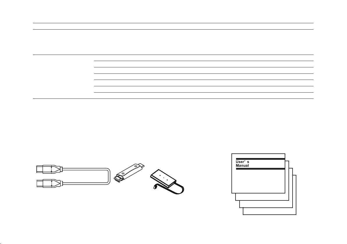
Standard Accessories
The following accessories are included. Make sure that all accessories are present and undamaged.
A1681WL
* IM AQ1210-01EN and IM AQ1210-17EN are contained in a PDF file in this
instrument internal memory. A printed manual can also be purchased separately.
4
B8070CX
(lithium-ion)
739884
IM AQ1210-02EN
・
(this manual)
PIM113-01Z2
・
(List of contacts)
IM AQ1210-92Z1
・
(for Chaina)
IM 739884-01Z1
・
(Battery pack)
IMAQ1210-02
PIM113-01Z2
IMAQ1210-92Z1
IM739884-01Z1
IM AQ1210-02EN
Page 6

Optional Accessories
The following optional accessories are available for purchase separately. For information about ordering accessories, contact your
nearest YOKOGAWA dealer.
Item Model/Part No. Note
Soft carrying case SU2006A —
Shoulder strap B8070CY —
USB Cable (TypeC to TypeC) A1681WL —
Battery pack 739884 —
Universal adapter (SC) 735482-SCC For the OTDR port (SC type), fixing screws (2 pcs.)
For the PON optical power measurement port (/PPM option), fixing screws (2 pcs.)
Universal adapter (FC) 735482-FCC For the OTDR port (FC type), fixing screws (2 pcs.)
For the PON optical power measurement port (/PPM option), fixing screws (2 pcs.)
Universal adapter (LC) 735482-LCC For the OTDR port (LC type), fixing screws (2 pcs.)
For the PON optical power measurement port (/PPM option), fixing screws (2 pcs.)
Universal adapter (SC Angled-PC) 735482-ASC For the OTDR port, fixing screws (2 pcs.)
For the PON optical power measurement port (/PPM option), fixing screws (2 pcs.)
Connector adapter (SC) 735480-SCC For optical power measurement (OPM) ports with an SC connector.
For products with the /SPM or /HPM option.
Connector adapter (FC) 735480-FCC For optical power measurement (OPM) ports with an FC connector.
For products with the /SPM or /HPM option.
Ferrule adapter (ɸ1.25) 735481-LMC For optical power measurement (OPM) ports.
For products with the /SPM or /HPM option.
Ferrule adapter (ɸ2.5) 735481-SFC For optical power measurement (OPM) ports.
For products with the /SPM or /HPM option.
Additional Option License for
AQ1210
Emulation software AQ7933 Software for PC. Analysis of trace data function, report creation wizard
Accessories (sold separately) are not covered by warranty.
735051-FST Fiber surface test function
function.
IM AQ1210-02EN
5
Page 7

Conventions Used in This Guide
Notes
The notes and cautions in this guide are categorized using the following symbols.
Improper handling or use can lead to injury to the user or damage to the instrument. This symbol appears on the
instrument to indicate that the user must refer to the user’s manual for special instructions. The same symbol appears
in the corresponding place in the user’s manual to identify those instructions. In the manual, the symbol is used in
conjunction with the word “WARNING” or “CAUTION.”
WARNING
CAUTION
French
Une manipulation ou une utilisation incorrectes risquent de blesser l’utilisateur ou d’endommager l’instrument. Ce
AVERTISSEMENT
ATTENTION
Note
6
Calls attention to actions or conditions that could cause serious or fatal injury to the user, and precautions that can
be taken to prevent such occurrences.
Calls attention to actions or conditions that could cause light injury to the user or damage to the instrument or
user’s data, and precautions that can be taken to prevent such occurrences.
symbole apparaît sur l’instrument pour indiquer à l’utilisateur qu’il doit se reporter au manuel de l’utilisateur afin d’y lire
les instructions spécifiques correspondantes. Ce même symbole apparaît à la section correspondante du manuel de
l’utilisateur pour signaler lesdites instructions. Dans le manuel de l’utilisateur, ce symbole est accompagné des termes
AVERTISSEMENT et ATTENTION.
Attire l’attention sur des gestes ou des conditions susceptibles de provoquer des blessures graves (voire
mortelles), et sur les précautions de sécurité pouvant prévenir de tels accidents.
Attire l’attention sur des gestes ou des conditions susceptibles de provoquer des blessures légères ou
d’endommager l’instrument ou les données de l’utilisateur, et sur les précautions de sécurité susceptibles de
prévenir de tels accidents.
Calls attention to information that is important for the proper operation of the instrument.
IM AQ1210-02EN
Page 8
Safety Precautions
This product is designed to be used by a person with specialized knowledge. The general safety precautions described herein must be
observed during all phases of operation. If the product is used in a manner not specified in this manual, the protection provided by the
product may be impaired. This manual is part of the product and contains important information. Store this manual in a safe place close
to the instrument so that you can refer to it immediately. Keep this manual until you dispose of the instrument.
YOKOGAWA assumes no liability for the customer’s failure to comply with these requirements.
The following symbols are used on this instrument.
Warning: handle with care. Refer to the user’s manual or service manual. This symbol appears on dangerous locations on the
instrument which require special instructions for proper handling or use. The same symbol appears in the corresponding place in
the manual to identify those instructions.
Hazard, radiation of laser apparatus
IM AQ1210-02EN
Direct current
Stand-by
French
Avertissement : À manipuler délicatement. Toujours se reporter aux manuels d’utilisation et d’entretien. Ce symbole a été apposé
aux endroits dangereux de l’instrument pour lesquels des consignes spéciales d’utilisation ou de manipulation ont été émises.
Le même symbole apparaît à l’endroit correspondant du manuel pour identifier les consignes qui s’y rapportent
Danger : Appareil laser à rayonnement.
Courant direct
Veille
7
Page 9

Failure to comply with the precautions below could lead to injury or death or damage to the instrument.
WARNING
Use the Instrument Only for Its Intended Purpose
This optical measuring instrument is designed to measure the optical characteristics of light sources and evaluate their
performance. Do not use this instrument for anything other than as an optical measuring instrument.
Check the Physical Appearance
Do not use the instrument if there is a problem with its physical appearance.
Battery
• This instrument contains a battery (lithium-ion cell). The battery cannot be removed. For information on replacing the
battery, contact your nearest YOKOGAWA dealer.
• Use only the supplied USB cable to charge the instrument.
• With the instrument turned off, when the battery pack is charged using the USB-AC adapter that YOKOGAWA
recommends , if the battery pack is still charging after 8 hours, stop charging it immediately.
• Do not charge the instrument under direct sunlight (such as on the car dashboard or by a window), inside a vehicle
under the blazing sun, near a stove or other heat source, or other hot locations.
• Your clothing may be damaged or you may be injured if you come in contact with the electrolyte in the battery due to
fluid leakage or the battery exploding. Because the electrolyte may cause loss of eyesight, if it comes in contact with
your eyes, immediately wash the affected area with clean water, and consult a doctor as soon as possible.
• Do not throw the instrument into fire or heat it. Such actions are dangerous as they may cause the battery to explode
or the electrolyte to be sprayed about.
• For information on transporting lithium-ion batteries by air, see the requirement for each packing instruction (lithium
batterying instruction Section II) in the latest IATA Dangerous Goods Regulations.
Laser Beam
Do not look directly or indirectly into the laser beam or at a specular reflection of the beam without protective equipment.
Do not aim the laser beam at the eye. Doing so may cause blindness or damage to your eyes. Attach the cover to the
optical connector when it is not in use. Be sure to turn off this instrument before you clean it.
8
IM AQ1210-02EN
Page 10

Connecting Optical Fiber Cables
Use optical fiber cables that are compatible with the universal adapter (the universal adapter is specified with a suffix
code).
TypeA USB port
Only use the USB memory device or USB dongle that YOKOGAWA recommends. YOKOGAWA provides no guarantee
if you use the device that YOKOGAWA do not recommend. This instrument may be powered off without alarm forcibly if
you use the device that YOKOGAWA do not recommend.
Applying Light to the Optical Connector
Do not apply light that is –5 dBm or greater to the optical connector of the OTDR port. Doing so can damage the
instrument. Do not apply light that is +10 dBm or greater to the OPM port/PON-OPM port (1310 nm/1490 nm). Do not
apply light that is +27 dBm or greater to the high power OPM port/PON-OPM port (1550 nm). Doing so may damage
the OPM port.
Do Not Operate in an Explosive Atmosphere
Do not use this instrument in the presence of flammable gases or vapors. Doing so is extremely dangerous.
Do Not Remove Covers or Disassemble or Alter the Instrument
Only qualified YOKOGAWA personnel may remove the covers and disassemble or alter the instrument.
Installation Location
Using a stand in an unstable location is extremely dangerous. If you are installing the instrument using a stand, install
in a stable location.
CAUTION
Operating Environment Limitations
This product is a Class A (for industrial environments) product. Operation of this product in a residential area may cause
radio interference in which case the user will be required to correct the interference.
IM AQ1210-02EN
9
Page 11

French
AVERTISSEMENT
Utiliser l’instrument aux seules fins prévues
Cet instrument de mesure optique est prévu pour mesurer les caractéristiques optiques des sources lumineuses et
évaluer leur performance. Ne pas utiliser cet instrument à d’autres fins que celles de mesure optique.
Inspecter l’apparence physique
Ne pas utiliser l’instrument si son intégrité physique semble être compromise.
Batterie
• Cet instrument contient une batterie (cellule au lithium-ion). La batterie ne peut être retirée. Pour plus d'informations
sur le remplacement de la batterie, contacter votre fournisseur YOKOGAWA le plus proche.
• Utiliser uniquement le câble USB fourni pour charger l'instrument.
• Avec l'instrument hors tension, lorsque le pack de batteries est chargé à l'aide de l'adaptateur USB-CA recommandé
par YOKOGAWA, si le pack de batteries est encore en charge après 8 heures, arrêter le chargement immédiatement.
• Ne pas charger l'instrument en plein soleil (par exemple sur le tableau de bord de la voiture ou sur le rebord d'une
fenêtre), dans un véhicule stationné sous un soleil de plomb, à proximité d'une gazinière ou de toute autre source de
chaleur ou dans tout autre endroit chaud.
• Tout contact avec l'électrolyte échappé en raison d'une fuite ou d'une explosion du pack de batteries peut
endommager les vêtements ou causer des blessures. L'électrolyte peut entraîner la cécité, par conséquent, en cas
de contact avec les yeux, rincer immédiatement à l'eau et consulter un médecin dans les plus brefs délais.
• Tenir le pack de batteries éloigné de toute source de chaleur et des flammes pour éviter le risque d'explosion du
pack de batteries ou de déversement d'électrolyte.
• Pour toute information sur le transport aérien des batteries au lithium-ion, consulter les exigences énoncées dans le
Règlement de l'IATA sur le transport des marchandises dangereuses (instruction sur les batteries au lithium).
Faisceau laser
Ne pas fixer directement ou indirectement le faisceau laser, ni la réflexion spéculaire du faisceau en l’absence
d’équipement de protection. Ne pas orienter le faisceau laser en direction des yeux. Le faisceau laser peut entraîner la
cécité ou causer des lésions oculaires. Recouvrir le connecteur optique à l’aide du cache pendant les périodes de nonutilisation. Mettre cet instrument HORS tension pendant son nettoyage.
10
IM AQ1210-02EN
Page 12

Connexion des câbles à fibre optique
Utiliser des connecteurs de câbles à fibre optique conformes à l’adaptateur universel fourni (adaptateur universel
indiqué par le suffixe).
Envoyer un signal au connecteur optique
Ne pas appliquer un signal de -5 dBm ou plus au connecteur optique du port OTDR. Cela pourrait endommager
l'instrument. Ne pas appliquer de signal de +10 dBm ou plus au port OPM/PON-OPM (1310 nm/1490 nm). Ne
pas appliquer de signal de +27 dBm ou plus au port OPM/PON-OPM (1550 nm) haute puissance. Cela pourrait
endommager le port OPM.
Ne pas utiliser dans un environnement explosif
Ne pas utiliser l’instrument en présence de gaz ou de vapeurs inflammables. Cela pourrait être extrêmement
dangereux.
Ne pas retirer le capot, ni démonter ou modifier l’instrument
Seul le personnel YOKOGAWA qualifié est habilité à retirer le capot et à démonter ou modifier l’instrument. Certains
composants à l’intérieur de l’instrument sont à haute tension et par conséquent, représentent un danger.
Position d’installation
Lorsque vous manipulez les pieds ou le support escamotable, soutenez toujours l’instrument fermement. Prendre les
précautions suivantes.
ATTENTION
Limitations relatives à l’environnement opérationnel
Ce produit est un produit de classe A (pour environnements industriels). L’utilisation de ce produit dans un zone
résidentielle peut entraîner une interférence radio que l’utilisateur sera tenu de rectifier.
IM AQ1210-02EN
11
Page 13
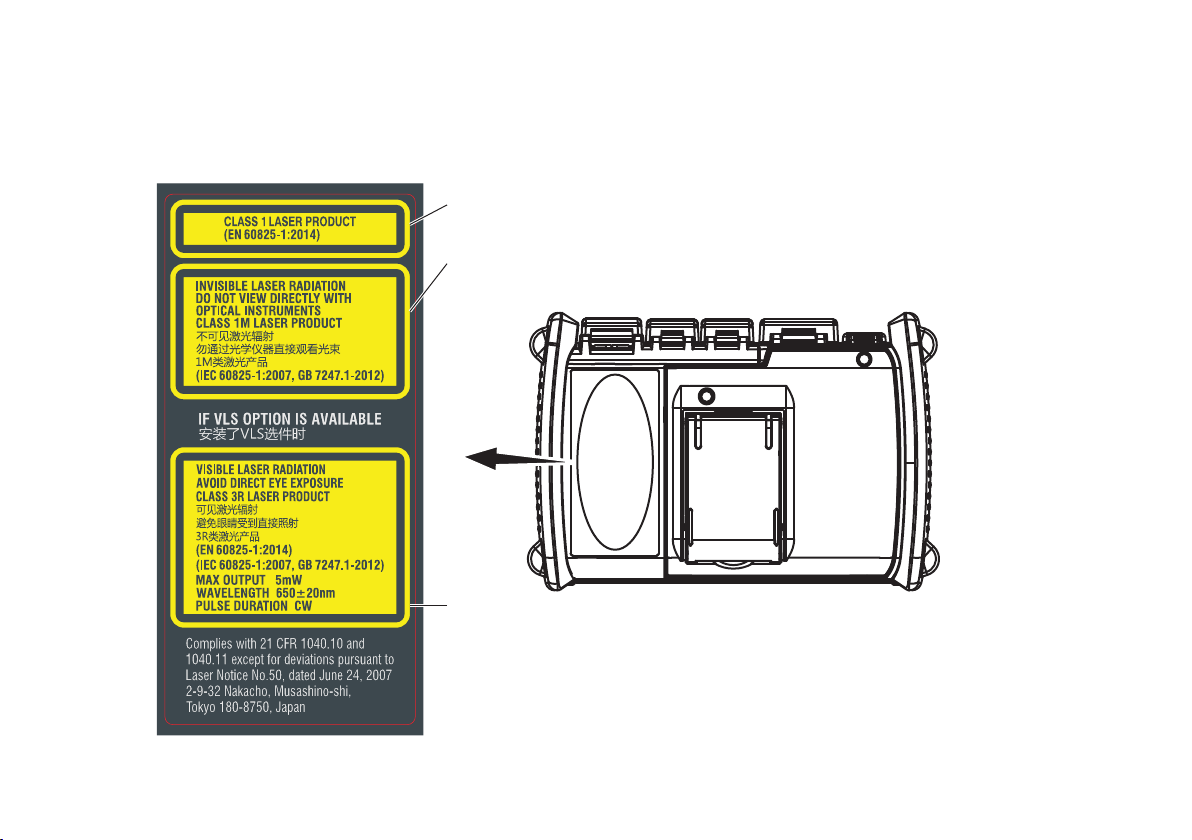
Safety Precautions for Laser Products
This instrument uses a laser light source. This instrument is a Class 1M laser product and Class 3R laser product as defined by
IEC60825-1:2007 Safety of Laser Products-Part 1: Equipment classification and requirements. In addition, this instrument complies with
21 CFR 1040.10 and 1040.11 except for deviations pursuant to Laser Notice No. 50, dated June 24, 2007.
Laser Class 1 Label
Avoid direct eye exposure.
Laser Class 1M Label
Using an optical instrument, such as a loupe, magnifying glass, or microscope, when
observing the laser beam from a distance of less than 100 mm may cause eye injury.
Laser Class 3R Label
Avoid direct eye exposure.
12
IM AQ1210-02EN
Page 14

OTDR Port
Model Class1Center
Maximum Output Power
Wavelength
AQ1210A
OTDR port (PORT1) 1M or 1 1310 nm/1550 nm CW: 50 mW,
Pulse: 200 mW, Pulse width: 20 μs, Duty: ≤ 3.0%
VLS port
3
3R 650 nm CW: 5 mW 9 μm 11.5°
AQ1215A
OTDR port (PORT1) 1M or 1 1310 nm/1550 nm CW: 50 mW,
Pulse: 200 mW, Pulse width: 20 μs, Duty: ≤ 3.0%
VLS port
3
3R 650 nm CW: 5 mW 9 μm 11.5°
AQ1210E
OTDR port (PORT1) 1M or 1 1310 nm/1550 nm CW: 50 mW,
Pulse: 200 mW, Pulse width: 20 μs, Duty: ≤ 3.0%
OTDR port (PORT2) 1M or 1 1625 nm CW: 50 mW, Pulse: 200 mW, Pulse width: 20 μs,
Duty: ≤ 3.0%
VLS port
3
3R 650 nm CW: 5 mW 9 μm 11.5°
AQ1215E
OTDR port (PORT1) 1M or 1 1310 nm/1550 nm CW: 50 mW,
Pulse: 200 mW, Pulse width: 20 μs, Duty: ≤ 3.0%
OTDR port (PORT2) 1M or 1 1625 nm CW: 50 mW,
Pulse: 200 mW, Pulse width: 20 μs, Duty: ≤ 3.0%
VLS port
3
3R 650 nm CW: 5 mW 9 μm 11.5°
AQ1215F
OTDR port (PORT1) 1M or 1 1310 nm/1550 nm CW: 50 mW,
Pulse: 200 mW, Pulse width: 20 μs, Duty: ≤ 3.0%
OTDR port (PORT2) 1M or 1 1650 nm CW: 50 mW,
Pulse: 200 mW, Pulse width: 20 μs, Duty: ≤ 3.0%
VLS port
3
3R 650 nm CW: 5 mW 9 μm 11.5°
2
Mode Field
Diameter
Beam Divergence
Angle
9 μm 11.5°
9 μm 11.5°
9 μm 11.5°
9 μm 11.5°
9 μm 11.5°
9 μm 11.5°
9 μm 11.5°
9 μm 11.5°
IM AQ1210-02EN
13
Page 15

Model Class1Center
Wavelength
AQ1216F
OTDR port (PORT1) 1M or 1 1310 nm/1550 nm CW: 50 mW,
OTDR port (PORT2) 1M or 1 1650 nm CW: 50 mW,
VLS port
1 Class 1M: IEC 60825-1:2007, GB 7247.1-2012,
Class 1: EN 60825-1:2014
2 Under single fault conditions.
3 Applicable to models with the /VLS option.
3
3R 650 nm CW: 5 mW 9 μm 11.5°
Maximum Output Power
Pulse: 200 mW, Pulse width: 20 μs, Duty: ≤ 3.0%
Pulse: 200 mW, Pulse width: 20 μs, Duty: ≤ 3.0%
2
Mode Field
Diameter
9 μm 11.5°
9 μm 11.5°
Beam Divergence
Angle
Regulations and Sales in Each Country or Region
Waste Electrical and Electronic Equipment
(This directive is valid only in the EU.)
This product complies with the WEEE Directive marking requirement. This marking indicates that you must not discard this
electrical/electronic product in domestic household waste.
Product Category
With reference to the equipment types in the WEEE directive, this product is classified as a “Monitoring and control instruments ”
product. When disposing of products in the EU, contact your local Yokogawa Europe B.V. office.
Do not dispose in domestic household waste.
14
IM AQ1210-02EN
Page 16

EU Battery Directive
(This directive is valid only in the EU.)
Batteries are included in this product. This marking indicates they shall be sorted out and collected as ordained in the EU battery
directive.
Battery type:
1. Lithium battery
You cannot replace batteries by yourself. When you need to replace batteries, contact your local Yokogawa Europe B.V.
office.
2. Lithium-ion battery
When you remove batteries from this product and dispose them, discard them in accordance with domestic law
concerning disposal. Take a right action on waste batteries, because the collection system in the EU on waste batteries
are regulated. For instructions on how to remove the battery pack, see page 64.
Recycle Mark
Do not dispose together with normal garbage. To protect the environment, please dispose according to the recycling ordinances
in your area.
Authorized Representative in the EEA
Yokogawa Europe B.V. is the authorized representative of Yokogawa Meters & Instruments Corporation for this product in the EEA. To
contact Yokogawa Europe B.V., see the separate list of worldwide contacts, PIM 113-01Z2.
IM AQ1210-02EN
15
Page 17
How to View the User’s Manual
AQ1215F, AQ1216F
The following PDF file is stored in the USERS_MANUAL folder in this instruments internal memory.
File Name Manual Title Manual No.
Features & Operation Manual_*.pdf
“*“ is used to indicate the revision number.
Communication Interface_*.pdf
“*“ is used to indicate the revision number.
To view the PDF file above, you need Adobe Reader 5.0 or later. Follow the procedure below to open the PDF file.
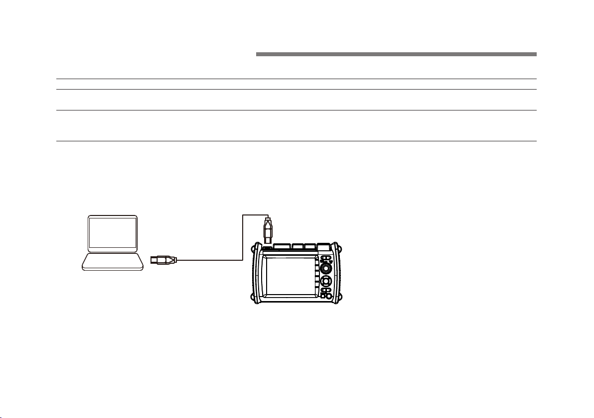
Turn on the instrument.
1.
Connect the type B (editionMicro-B) USB port on the top panel of the instrument to the type A USB port of the PC with the supplied
2.
USB cable. For a description of the top panel, see “Component Names and Functions.” If the instrument is connected to the PC for
the first time as a mass storage device, a USB driver is automatically installed in the PC.
AQ1210A, AQ1215A, AQ1210E, AQ1215E, AQ1215F,
AQ1216F OTDR Multi Feild Tester User’s Manual
AQ1210A, AQ1215A, AQ1210E, AQ1215E, AQ1215F,
AQ1216F OTDR Multi Feild Tester Communication
Interface User’s Manual
IM AQ1210-01EN
IM AQ1210-17EN
PC
TypeC
On your PC, start Explorer or other browser. The folder in the instruments internal memory will be displayed.
3.
Open the /USER/DATA/USERS_MANUAL folder. The following PDF file will be displayed.
4.
Open the PDF file. The user’s manual appears on the computer screen.
5.
USB cable
AQ1210A, AQ1215A,
AQ1210E, AQ1215E,
TypeC
The ends of the USB cable supplied with
the product are both Type-C. If the USB
port on your PC is of a different type,
prepare your own USB cable.
16
IM AQ1210-02EN
Page 18

Contents
Product Registration ................................................................2
Checking the Contents of the Package ...................................3
Conventions Used in This Guide .............................................6
Safety Precautions ..................................................................7
Regulations and Sales in Each Country or Region ...............14
How to View the User’s Manual ............................................16
Component Names and Functions
Front Panel ............................................................................19
Top Panel ..............................................................................20
Rear and Side Panels ...........................................................21
Making Preparations for Measurements
Handling Precautions ............................................................22
Attaching the Strap ................................................................23
Attaching the Battery Pack ....................................................24
Connecting the USB-AC Adapter and Charging
the Instrument .......................................................................27
Connecting Optical Fiber Cables ..........................................31
Turning the Power On ...........................................................34
Screen Operations
MENU Screen .......................................................................35
OTDR Measurement Screen .................................................36
Using the Rotary Knob and Arrow Keys ................................38
Using the Touch Panel ..........................................................39
Entering Text .........................................................................40
IM AQ1210-02EN
............................................................35
...........................19
................22
Setting the Language and Date and Time
Selecting the Language to Display........................................41
Selecting the Date and Time to Display ................................42
.......................................................................................43
Setup
Setting Measurement Conditions (Measure) .........................43
Setting the Analysis Conditions (Analysis) ............................44
Setting Display Conditions (OTDR) .......................................45
Waveform Measurement
Performing Real-time Measurement .....................................46
Performing High-Precision Waveform Monitoring in Real-time .
47
Cutting the Waveform Display Noise ....................................47
Performing Averaged Measurements .................................... 48
Analyzing Waveforms and Events
Measuring the Distance and Loss between Two Points ........49
Measuring the Return Loss ...................................................50
Measuring the Splice Loss ....................................................51
Zooming In on or Out of Waveforms .....................................52
Analyzing Events ...................................................................53
Creating Reports
Exporting the Waveforms on the Screen to Report Files ......55
Exporting File List Data to Report Files .................................56
...............................................................55
................................................46
............................49
.............41
17
Page 19

Background Information on Measurements
How to View Optical Pulse Measurement Waveforms (TRACE
screen) ..................................................................................58
How to View the Icon Display (MAP Screen) ........................59
Terminology ...........................................................................60
........58
Analysis using the Emulation Software
Maintenance and Inspection
Replacing the Optical Adapter ...............................................62
Removing the Battery Pack ...................................................64
Recommended Part Replacement ........................................66
Disposing of the Instrument ..................................................66
........................................62
.................61
Specifications .......................................................67
Optical Pulse Measurement (OTDR) ....................................67
Power Checker (/PC option) .................................................68
Optical Power Meter (Option) ................................................69
Light Source ..........................................................................69
Visible Light Source (/VLS option) ........................................70
Functions ...............................................................................70
General Specifications ..........................................................71
External Dimensions .............................................................72
18
IM AQ1210-02EN
Page 20
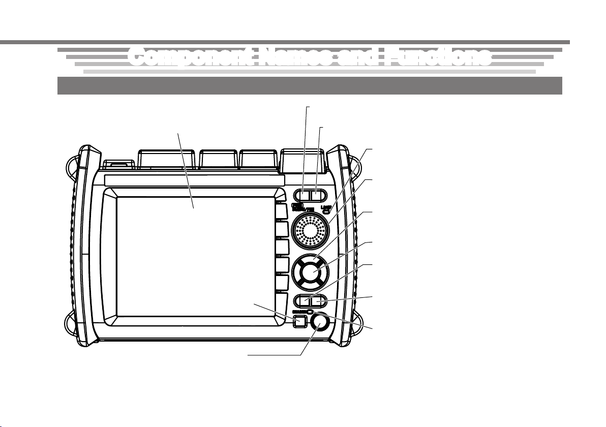
Component Names and Functions
battery is low. The LED illuminates in red for an instant during startup, but this does not indicate the battery level.
REAL TIME key
Front Panel
LCD
Used to perform touch panel operations.
IM AQ1210-02EN
Press to start or stop the real-time measurement of optical pulses.
AVG Key
Press to start or stop the averaged measurement of optical pulses.
ESC key
Press to return to the previous menu
or to cancel the current operation.
Power switch (POWER LED)
Press to turn the instrument on and off. Illuminates in green when the instrument is running. Illuminates in red when the
LASER LED
Illuminates in red when the light is being emitted
from the light source port.
Rotary knob
Turn to select features, change settings, and
move the cursor.
Arrow keys
Press to change values, move between digits,
move cursors, and zoom waveforms.
ENTER key
Press to confirm procedures and settings.
MENU key
Press to select the features (OTDR, Smart
Mapper or like) used this istrument.
SETUP key
Press to display the measurement conditions,
system setup, and file operation menus.
CHARGE LED
Illuminates in red when the battery is being
charged. It turns off when charging is complete.
19
Page 21
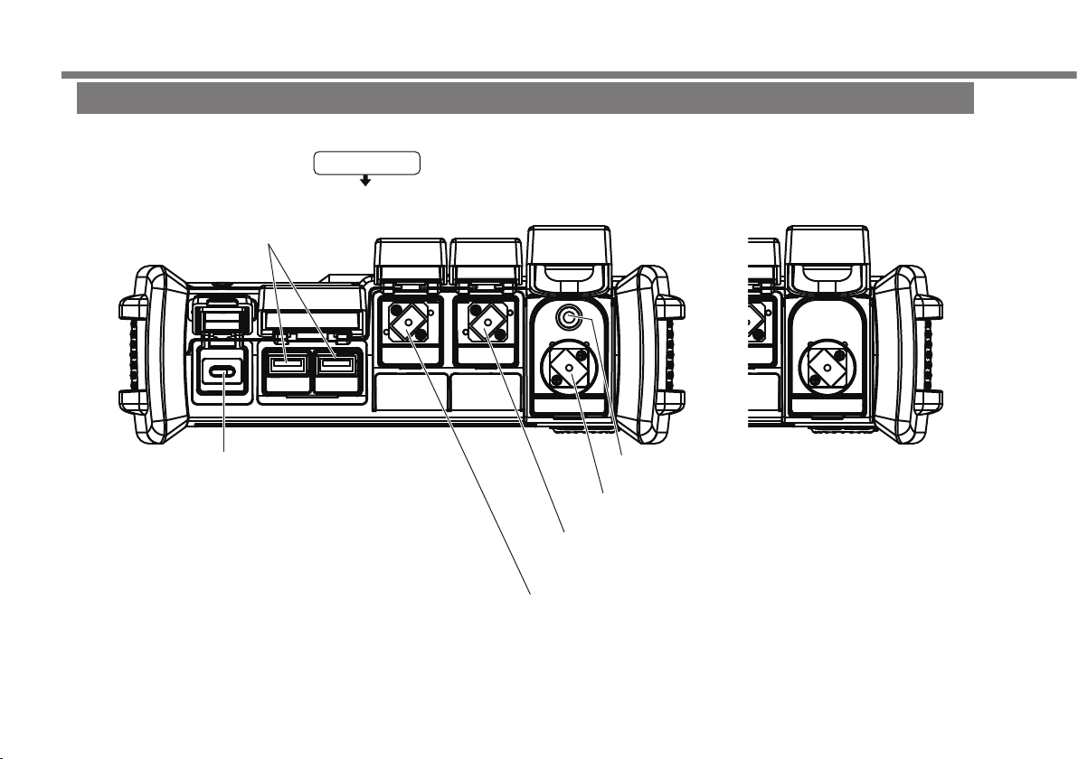
Type C USB port
Used to charge the instrument with the USB-AC
adapter and to access the instrument internal
memory (USB mass storage) from a PC. Note
that the charging function and USB mass storage
function cannot be used simultaneously.
without /VLS option
Used for OTDR measurement (1625 nm/1650 nm).
Component Names and Functions
Type A USB port
Used to connect a USB memory
device or USB dongle.
20
Top Panel
Rear panel
VLS port (/VLS option)
Used for VLS output.
OPM port (/SPM, /HPM, or /PPM option)
Used for OPM input.
OTDR port (PORT1)
Used for OTDR measurement (1310 nm/1550 nm), power
checker measurement (/PC option), and light source output.
OTDR port (PORT2)
IM AQ1210-02EN
Page 22
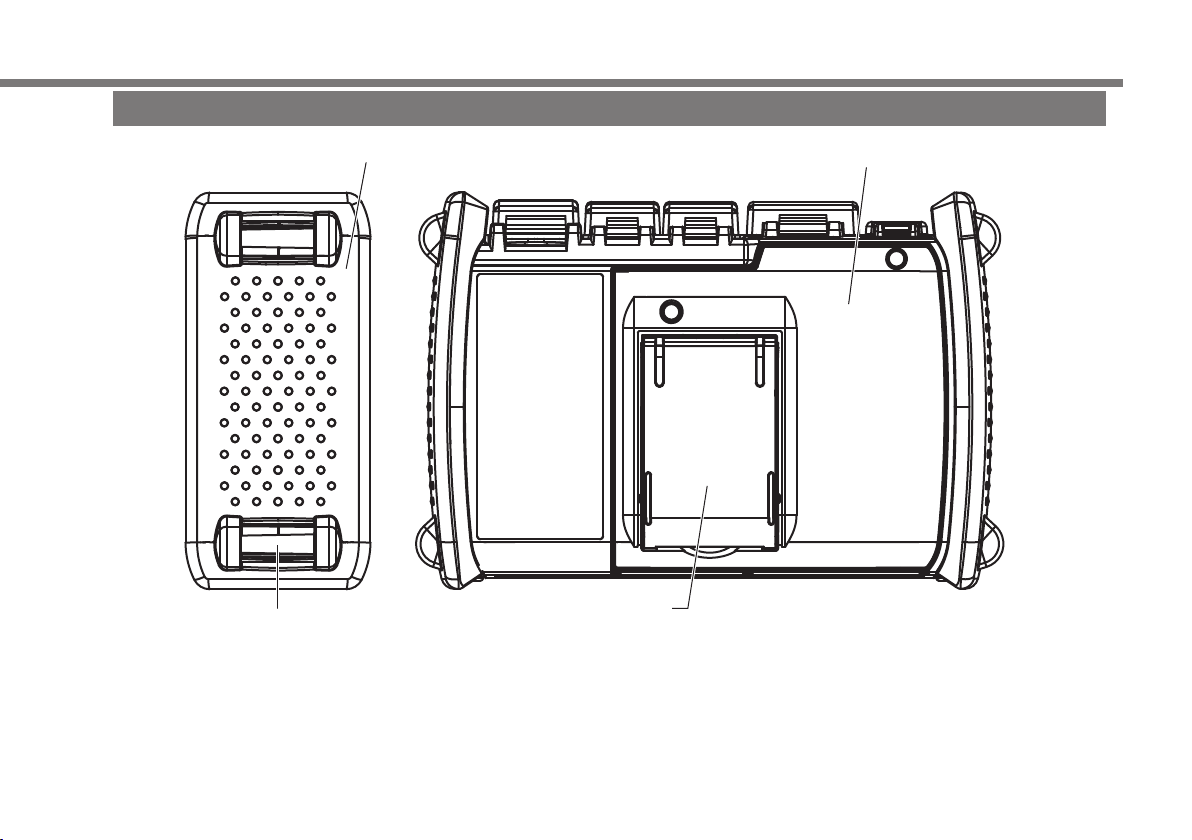
Pull the stand out to use the instrument in a tilted position.
Protector
Component Names and Functions
Rear and Side Panels
Battery cover
IM AQ1210-02EN
Strap slot
Stand
21
Page 23

Making Preparations for Measurements
Handling Precautions
Safety Precautions
If you are using this instrument for the first time, make sure to thoroughly read “Safety Precautions,” on pages 7 to 14.
Do Not Remove the Case
Do not remove the case from the instrument. Doing so is extremely dangerous. For internal inspection, adjustment and battery
replacement, contact your nearest YOKOGAWA dealer.
Unplug If Abnormal Behavior Occurs
If you notice smoke or unusual odors coming from the instrument, immediately turn off the power, unplug the USB-AC adapter, remove
the battery pack and contact your nearest YOKOGAWA dealer.
Handle the USB-AC Adapter and USB Cable Properly
Do not place objects on top of the USB-AC adapter or USB cable, and keep them away from heat sources.
General Handling Precautions
Do Not Place Objects on Top of the Instrument
Never place objects such as other instruments or objects that contain water on top of the instrument. Doing so may damage the
instrument.
Do Not Subject the OTDR Port or VLS Port to Mechanical Shock
If the optical connectors or universal adapters are subjected to mechanical shock, they may be damaged. The instrument may not
perform measurements correctly due to damage or deformation that is not visible to the naked eye.
Do Not Scratch the LCD
Because the LCD can be easily scratched, do not allow any sharp objects near it. Also, do not apply vibration or shock to it. Do not apply
strong shock to the LCD or place objects on top of it.
When Carrying the Instrument
First, remove all cables including the USB cable and optical fiber cable. When carrying the instrument, grasp the protector or the
attached strap firmly.
22
IM AQ1210-02EN
Page 24

Hand strap
2
Pass the shoulder strap through the loops and then the buckle
1
Strap loops
Buckle
Attaching the Strap
Attaching the Hand Strap
3
Attaching the Shoulder Strap
4
Buckle
Making Preparations for Measurements
Pass the hand strap through the
1.
loop on the lower-left side of the
instrument.
Pass the hand strap through the
2.
hand strap cover.
Pass the hand strap through the
3.
loop on the upper-left side of the
instrument.
Pass the strap through the buckle,
4.
and use the buttons to close the
hand strap cover.
IM AQ1210-02EN
Shoulder strap
Strap loop
Buckle
Pass the belt back through
the buckle and tighten it.
Attach the strap to the loops on both the upper-left and
upper-right sides of the instrument. These loops are also used
when attaching the hand strap, but you cannot attach both the
shoulder strap and the hand strap at the same time.
as shown in the figure. In the same manner, attach the strap
to the other side of the instrument.
23
Page 25

Making Preparations for Measurements
WARNING
• Do not connect or disconnect the battery pack while electricity is being supplied by the AC adapter.
• To prevent problems before they occur, periodically inspect the battery pack exterior to confirm that there is no
damage such as cracks or deformations and to confirm that there is no fluid leakage.
• Use the instrument to charge the battery pack. Maintain the correct environmental conditions when the battery pack
is charging. Failure to do so can cause fluid leakage, heating, smoke, explosions, or fire.
• Follow the handling precautions that are included in the battery pack’s user’s manual.
French
AVERTISSEMENT
• Ne pas installer, ni déposer le pack de batteries lorsque l’électricité est alimentée par l’adaptateur USB-CA.
• À titre préventif, inspecter régulièrement le boîtier extérieur du pack de batteries afin de déceler tout signe
d’endommagement, comme l’apparition de fissures ou de déformations, et vérifier qu’il n’y a aucune fuite.
• Recharger le pack de batteries à l’aide de cet instrument. Respecter les consignes environnementales prescrites
pour la recharge du pack de batteries, afin d’éviter les risques de fuite, de surchauffe, de fumée, d’explosion ou
d’incendie.
• Respecter les consignes de manipulation indiquées dans le manuel d’utilisation du pack de batteries.
Attaching the Battery Pack
24
IM AQ1210-02EN
Page 26

1.
Loosen the battery cover screws with a Phillips
3.
Connect the battery pack’ s power supply lead wire
sure that the power supply lead wires do not protrude from the battery
Battery pack
Making Preparations for Measurements
screwdriver until the screw head moves up and down.
Pull the battery cover toward you, lift, and remove.
2.
Screws
Secure the power supply lead wires on the
4.
instrument’ s cable hook.
Cable hook
Battery cover
Plug
Label with
barcode
Battery pack
Power supply lead wires
plug to the instrument’ s battery connector.
Battery pack
Plug
Insert the battery pack so that the power supply lead wires are facing
5.
the bottom panel side from the lower right of the battery pack. Make
case. Check that the entire battery pack is completely inside the case.
Label with
barcode
The lead wires are
from the lower right
of the battery pack.
Face the hook of
the plug toward
the bottom panel
side.
Battery cover
Hooks
IM AQ1210-02EN
25
Page 27

6.
Attach the battery cover from the bottom panel side,
7.
Check that the battery cover is not loose, and then fasten
Making Preparations for Measurements
making sure that the hooks on the battery cover enter
into their holes on the case.
Battery cover
the attachment screws with a Phillips screwdriver.
Tightening torque: Approx. 0.4 N.m
Screws
26
IM AQ1210-02EN
Page 28

Connecting the USB-AC Adapter and Charging the Instrument
WARNING
• Only use the USB-AC adapter that YOKOGAWA recommends.
• Use the USB-AC adapter after confirming that the rated supply voltage matches the voltage of the power supply.
• Use only the supplied USB cable.
French
AVERTISSEMENT
• Utiliser l’adaptateur USB-CA recommandé par YOKOGAWA.
• Utiliser l’adaptateur USB-CA après confirmation que la tension d’alimentation nominal correspond à la tension
d’alimentation.
• Utiliser uniquement le câble USB fourni.
Making Preparations for Measurements
IM AQ1210-02EN
27
Page 29

Making Preparations for Measurements
Connect one end of the supplied USB cable to the type C USB port of the instrument.
1.
Connect the other end of the cable to the type A USB port of the USB-AC adapter.
2.
Connect the USB-AC adapter’s power plug to an outlet. The instrument’s CHARGE indicator turns on red.
3.
Supplied TypeC USB cable
AC outlet
USB-AC
Adapter
AQ1210A, AQ1215A,
AQ1210E, AQ1215E,
AQ1215F, AQ1216F
Note
• If the instrument’s connector cover comes off, bend the cover axle and reattach it.
• For details on the USB-AC adapter, contact your nearest YOKOGAWA dealer.
• The battery cannot be charged by connecting to a PC (YOKOGAWA provides no guarantee). Be sure to connect the USB-AC
adapter to charge the battery.
• Power supply icon blinks if the USB-AC adapter has insufficient power supply ability. Change to the USB-AC adapter recommended
by YOKOGAWA.
28
IM AQ1210-02EN
Page 30

Power switch (POWER LED)
Power switch
The power switch (POWER LED) lights in red,
a warning message appears on the screen.
Power supply status display
Making Preparations for Measurements
Charging the Instrument
• When the instrument’s battery is low, a warning message will appear.
• When the battery is low, connect the USB-AC adapter to an electrical outlet, and charge the instrument. For the estimated battery
level, check the battery level indicator at the top of the screen.
IM AQ1210-02EN
CHARGE
Green: Running
Red: Battery low
USB-AC adapter connected (Power supply icon)
CHARGE LED (red)
Solid: Charging
Off: Charging complete
Blinking: Charging suspended
• The battery pack may
be too cold or too hot.
• The battery pack
disconnected
Charging
Battery power level
Sufficiently full
Half full
Battery level indicator
Almost empty
• Charging takes about 5 hours with the power turned off. If the instrument is charged with the power turned on, it may take longer
than 15 hours, but charging will be suspended after about 15 hours by the protection circuit. If battery charging does not complete
within 8 hours with the power turned off, stop immediately. The battery in the instrument may be malfunctioning. Contact your nearest
YOKOGAWA dealer.
• Power supply icon
Power supply icon blinks if the USB-AC adapter has insufficient power supply ability. In this case, the battery pack charging may not
be completed because the battery pack becomes discharge. In addition, the battery pack may be dead if you continue use this USBAC adapter.
29
Page 31

Making Preparations for Measurements
Note
Over Discharge and Long Periods of Storage
• If you do not use the instrument for an extended period of time with the battery pack connected to it, the battery pack may become
over discharged. This shortens the service life of the battery pack. To avoid over discharging, if you will not use the instrument for
one week or longer, charge the battery pack, remove it from the instrument, and store the battery pack away from direct sunlight in a
location that has an ambient temperature of 10°C to 30°C.
• When you store the battery pack for six months or longer, to replace the power that has been lost through self discharge, recharge
the battery using the instrument once every six months.
• Avoid storing the battery pack for an extended period of time when it is fully charged (after it has just been charged) or when it has
no power left (when the instrument will not turn on). Storing the battery pack under these conditions will degrade its performance and
reduce its longevity. It is better to store the battery pack when it is 40% to 50% charged. This is equivalent to the state the battery is
in after you turn off the instrument and charge an empty battery for an hour at room temperature.
• Use the instrument to charge the battery pack prior to its first use or if it has not been used for an extended period of time.
30
IM AQ1210-02EN
Page 32

Making Preparations for Measurements
Connecting Optical Fiber Cables
WARNING
• When the instrument generates light, light is emitted from the light source ports. Do not disconnect the connected
optical fiber cables. Visual impairment may occur if the light enters the eye.
• Close the covers of any light source ports that do not have optical fiber cables connected to them. On models with
two or more light source ports, visual impairment may occur if light that is mistakenly emitted from the wrong port
enters the eye.
CAUTION
• Insert the optical fiber cable connectors slowly and straight into the optical ports. If you shake the connector to the
left and right or force it into the port, the optical connector or optical port may be damaged.
• If you use optical connectors that do not meet the specifications, the instrument optical ports may be damaged. Use
optical connectors that are approved or used by national or local telecom carriers and providers in your area.
• Use optical fiber cable connectors that conform to the included universal adapter and connector adapter (the
universal adapter specified by the suffix code).
Using SC Angled Physical Contact Connectors (Suffix code -ASC)
• The SC angled physical contact connector’s ferrule tip is angle-polished. Use optical fiber cables whose connectors
are of the same type. Using a different type of connector may damage the connector end face.
• Only use SC-type (735482-SCC) universal adapters on -ASC OTDR ports. Otherwise, the instrument optical ports or
the optical fiber cable connectors may be damaged.
IM AQ1210-02EN
31
Page 33

Making Preparations for Measurements
French
AVERTISSEMENT
• Lorsque cet instrument génère de la lumière, la lumière est émise à travers les ports de source lumineuse.
Ne pas débrancher les câbles de fibre optique connectés. Des lésions oculaires peuvent être causées si le faisceau
lumineux pénètre l’oeil.
• Couvrir les caches des ports de source lumineuse libres. Sur les modèles dotés de deux ports de source lumineuse
ou plus, protéger les yeux contre l’émission accidentelle de lumière depuis le mauvais port.
ATTENTION
• Insérer les connecteurs de câbles à fibre optique délicatement et sans les incliner dans les ports optiques. Éviter de
faire pression sur le connecteur ou de forcer pour l’insérer dans le port, car cela pourrait endommager le connecteur
optique ou le port optique.
• Toujours utiliser des connecteurs optiques conformes aux spécifications, à défaut de quoi les ports optiques de
cet instrument pourraient être endommagés. Utiliser des connecteurs optiques homologués ou utilisés par les
entreprises et les fournisseurs de services de télécommunications de votre région.
• Utiliser des connecteurs de câbles à fibre optique conformes à l’adaptateur universel et l’adaptateur de connecteur
fournis (adaptateur universel indiqué par le suffixe).
Utilisation de connecteurs de contact physique incliné SC (suffixe - ASC de l’unité OTDR)
• L’embout à ferrule du connecteur de contact physique incliné SC est poli. Utiliser des câbles à fibre optique dont
les connecteurs sont de même type. L’utilisation d’un autre type de connecteur peut endommager l’extrémité du
connecteur.
• Utiliser exclusivement des adaptateurs universels de type SC (735482-SCC) sur les ports ASC OTDR, pour éviter
d’endommager les ports optiques ou les connecteurs à fibre optique de cet instrument.
32
IM AQ1210-02EN
Page 34

1.
Firmly press the connector end face of the optical
2.
3.
4.
1.
Open the optical port cover on the instruments top panel.
s connector with the
Making Preparations for Measurements
Clean the connector end face of the optical fiber cable before connecting it to the instrument. If dust is adhered to the connector end
face, it may damage the instrument’s optical port. If this happens, the instrument will not be able to make correct measurements.
fiber cable against the cleaning surface of the
cleaner.
While pressing the end face against the cleaner, turn
the cable once.
While pressing the end face against the cleaner,
move the cable.
Repeat steps 1 to 3.
You can purchase an optical fiber
connector cleaner from NTT-AT
Corporation.
Note
• The optical port that you have to connect to varies depending on how you intend to use the instrument. Confirm which port light will
be transmitted from before you connect the optical fiber cable.
• On the AQ1210E, AQ1215E, AQ1215F and AQ1216F, light with a 1310 nm or 1550 nm wavelength is transmitted from OTDR port
(PORT1), and light with a 1625 nm or 1650 nm wavelength is transmitted from OTDR (PORT2).
Properly align the optical fiber cable’
2.
optical port, and insert the connector.
IM AQ1210-02EN
33
Page 35

Making Preparations for Measurements
Turning the Power On
Hold down the power switch on the instrument’s front panel for at least 2 seconds. When the instrument starts normally, the power
switch (POWER LED) lights, and the start screen appears.
When the Power-on Operation Does Not Finish Normally
Turn off the power switch, and check the following items.
• Is the USB-AC adapter connected correctly? See page 27.
• Are you holding down the power switch for at least 2 seconds?
If the instrument still does not work properly after checking these items, contact your nearest YOKOGAWA dealer for repairs.
Warm Up
To enable more accurate measurements, allow the instrument to warm up for at least 5 minutes after it is turned on.
Power-off and Sleep State
When the instrument is running normally with the power switch turned on, you can temporarily turn the power off to a sleep state.
The operation varies depending on how long you hold down the power switch.
• Turning the Power Off
If you hold down the power switch for 3 seconds or longer, a shutdown message appears on the screen, the power is turned off
completely, and the power switch (POWER LED) turns off.
• Sleep State
If you hold down the power switch for less than 3 seconds and release it, the screen turns off, and the instrument enters the sleep
state. In this case, the power switch (POWER LED) remains on. To release the sleep state, hold down the power switch. In the sleep
state, the instrument consumes the minimum amount of power. In the sleep state, the setup screen that you were using, the character
input screen, or the like is retained. When you turn on the power switch again, the original screen is restored. If the sleep state
continues for 2 hours, the power is turned off automatically.
34
IM AQ1210-02EN
Page 36

Screen Operations
OTDR Smart Mapper
Map display of line configuration
and events (see sec. 8.1)
(see sec. 9.4)
The references are chapters and sections in the User’s Manual, IMAQ1210-01EN.
MENU Screen
When you turn on the instrument or press MENU, the menu screen appears. You can change the screen that appears when you start the
instrument to the OTDR screen. For the setup procedure, see section 10.6 in the User’s Manual, IMAQ1210-01EN.
OTDR
Optical pulse measurement
(see chap. 2 to 6)
IM AQ1210-02EN
Power Meter
(see sec. 7.3)
Multi Fiber Project
Multi-core optical fiber cable
measurement (see sec. 8.2)
VLS Visible light source
(see sec. 7.2)
Fiber Inspec Probe
Fiber end face inspection
(see sec. 7.6)
View product
information
(see sec. 11.3)
SAVE
Save data (see
sec. 9.4)
LOAD
Load data
Light Source
Light source (see sec. 7.1)
Multicore Loss Test
(see sec. 8.4)
Power Checker
(see sec. 7.5)
Advanced Analysis
(see sec. 8.5)
(/PPM option)
Auto Loss Test
(see sec. 8.3)
PON Power Meter
PON power meter
(see sec. 7.4) (/PPM option)
FILE
Operate files (see sec. 9.6)
REPORT
Create report files
(see sec. 9.5)
35
Page 37

the power supply ability to TypeC
Utility button
Shows the light source,
optical power meter, and
other screens
(see chap. 7)
Set the index of refraction (see sec. 2.2).
The references are chapters and sections in the User’s Manual, IMAQ1210-01EN.
Screen Operations
OTDR Measurement Screen
TRACE Screen
Tap OTDR on the MENU screen. The OTDR measurement results are displayed as waveforms on the data display screen.
1.
Laser on indication
Data display screen
Averaged measurement in progress indication
Manage data (see chap. 9)
Shows/hides the utility
menu
Save displayed
waveforms (see sec. 3.4)
Set the wavelength.
Set the pulse width
(see sec. 2.1).
Set the attenuation
(see sec. 2.1).
Set the average times/duration
(see sec. 2.1).
Event
waveform
display
Set the distance range (see sec. 2.1).
Switches to the MAP screen.
Auto save indicator (see sec. 2.1)
Power supply icon display
Power supply icon
USB port is insufficient.
The battery pack may be dead if
you continue use this instrument
in this state.
Soft key menu
Tool control items appear
according to the feature
selected on the MENU screen.
Shows/hides the soft key menu
Overview display
Waveform analysis results (marker/event) (see sec. 1.4)
blinks if
36
IM AQ1210-02EN
Page 38

MAP Screen
Utility button
Shows the light source, optical
power meter, and other
screens (see chap. 7)
Set the index of refraction (see sec. 2.2).
The references are chapters and sections in the User’ s Manual, IMAQ1210-01EN.
the power supply ability to TypeC
Tap OTDR on the MENU screen. The OTDR measurement results are displayed as icons on the data display screen.
1.
Screen Operations
Laser on indication
Averaged measurement in progress indication
IM AQ1210-02EN
Manage data (see chap. 9)
Shows/hides the utility
menu
Save displayed waveforms
(see sec. 3.4)
Set the wavelength.
Set the pulse width
(see sec. 2.1).
Set the attenuation
(see sec. 2.1).
Set the average times/duration
(see sec. 2.1).
Event Icon Display
Set the distance range (see sec. 2.1).
Measure menu
Auto save indicator (see sec. 2.1)
Power supply icon display
Power supply icon
USB port is insufficient.
The battery pack may be dead if
you continue use this instrument
in this state.
Switches to the MAP screen.
Data display screen
During averaged measurement,
a progress bar is displayed.
Waveform analysis results
(marker/event)
(see sec. 1.4)
blinks if
37
Page 39

Move the cursor to the item that
The following setup operation patterns are available depending on the display
Screen Operations
Using the Rotary Knob and Arrow Keys
This section explains how to use the rotary knob and arrow keys using the ANALYSIS screen (partial extraction) of the SETUP item as
an example.
you want to set using the arrow
keys or the rotary knob.
38
button shape.
Press Enter to display following setup item.
Items set from a list of options
• Move the cursor to the item that you want to
select using the arrow keys or the rotary knob.
Items that require a value to be entered
70dB
OFF
Items toggle between on and off
Each time you press the key, the setting toggles
between ON and OFF.
Press Enter to display the detailed setup screen.
Press Enter to confirm the selected item or execute its
corresponding action.
• Press ENTER to confirm the selected item.
A numeric keypad appears.
Press ENTER to confirm the entered value.
IM AQ1210-02EN
Page 40

Using the Touch Panel
Pinch out Pinch in
The basic touch panel operations are described below.
Tap
Tap refers to the act of gently hitting the screen with your finger.
Tapping is used on the instrument screen to select areas with a mark, close a setup
menu, and so on.
Drag
Drag refers to the act of pressing your finger against the screen and sliding your finger.
Pinch Out and Pinch In
Pinch out refers to the act of pressing two fingers against the screen and spreading them
apart. Pinch in refers to the act of pressing two fingers against the screen and drawing
them together.
On a screen displaying waveforms, you can pinch out to zoom in and pinch in to zoom
out.
Screen Operations
IM AQ1210-02EN
39
Page 41

Screen Operations
Entering Text
When you select a setting, a character input dialog box appears if necessary. This section explains the operation after a character input
dialog box is displayed.
Entering Alphanumeric Characters
Deletes the character before the cursor position
Cursor
Moves the cursor to the right
Moves the cursor to the left
Deletes the entered text
40
Enters a symbol
Switches the keyboard language
The languages that appear vary depending on the language setting.
Switches between uppercase and lowercase
Space
Confirms the entered text
IM AQ1210-02EN
Page 42

Setting the Language and Date and Time
System Setup Screen
Selecting the Language to Display
Press MENU to display the MENU screen.
1.
Press SETUP to display the System Setup screen.
2.
Tap the Language button to display the language setup menu.
3.
IM AQ1210-02EN
Language setup
menu
The languages that
appear vary
depending on the
suffix code.
41
Page 43

System Setup Screen
(Off, Year/Month/Day Time, Day/Month/Year Time, Year,
Setting the Language and Date and Time
Selecting the Date and Time to Display
Press MENU to display the MENU screen.
1.
Press SETUP to display the System Setup screen.
2.
Tap the Date & Time Set button to display the following screen.
3.
Set the year,
month, and day.
Year, Month, and Date
The year is displayed according to the Gregorian calendar. The instrument supports leap years.
Hour, Minute, and Second
The hour can be set to a value from 0 to 23.
42
Set the hour, minute,
and second.
Confirms the settings
The set date and time are
displayed in the upper left
of the screen.
Set the date and time display format
IM AQ1210-02EN
Page 44

Setting Measurement Conditions (Measure)
MEASURE tab
Set wavelength 1.
Options vary depending on the model.
Set the sample interval
(Normal, High)
Fiber-in-use alarm on/off
Set wavelength 2.
.
their factory defaults.
Tap OTDR on the MENU screen.
1.
Press SETUP to display the setup screen.
2.
Tap the MEASURE tab to display the following screen.
3.
Setup
2.1, “Measurement (Measure) Conditions” in the User’s Manual
Set the distance range
(AUTO, 100m, 200m, 500m, 1km,
2km, 5km, 10km, 20km, 30km,
40km, 50km, 100km, 200km,
256km, 300km, 400km, 512km)
.
Set the average count or the
duration to average over.
• When the unit is times
AUTO, 2^10, 2^11, 2^12, 2^13,
2^14, 2^15, 2^16, 2^17, 2^18,
2^19, 2^20
• When the unit is duration:
AUTO, 5sec, 10sec, 20sec, 30sec,
1min, 3min, 5min, 10min, 20min,
30min
Auto event detection on/off
IM AQ1210-02EN
.
Turns connection check
on or off
Options vary depending on the model.
Executes initialization
Press to reset the settings to
Set the pulse width
(AUTO, 3nm/5nm1, 10nm, 20nm,
30nm, 50nm, 100nm, 200nm, 300nm,
500nm, 1μm, 2μm, 5μm, 10μm, 20μm)
1 The pulse widths that you can select is
5 ns on
AQ1210/AQ1210E
AQ1215A/AQ1215E/AQ1215F/AQ1216F
Set the attenuation
(AUTO, 0dB, 2.5dB, 5dB, 7.5dB,
10dB, 12.5dB, 15dB, 17.5dB, 20dB)
Set the average unit
(Duration, Times).
Set the average method
(Hi-Reflection, Hi-Speed).
Turns auto saving
on or off
, and 3 ns on
.
.
43
Page 45

ANALYSIS tab
Splice loss threshold
Bending loss threshold
(0.001dB to 99.999dB)
An event (bending) is
detected when this value
is exceeded.
Set the approximation
method (TPA, LSA).
An event is detected when this value
their factory defaults.
Setup
Setting the Analysis Conditions (Analysis)
Tap OTDR on the MENU screen.
1.
Press SETUP to display the setup screen.
2.
Tap the ANALYSIS tab to display the following screen.
3.
2.2, “Analysis (Analysis) Conditions” in the User’s Manual
(0.01dB to 9.99dB)
An event is detected
when this value is
exceeded.
End of fiber threshold
(3dB to 65dB)
An event E is detected
when this value is
exceeded.
Setting a Launch Fiber
Set the conditions for
when a launch fiber is
attached to the start or
end face.
44
Set the backscatter level.
Executes initialization
Press to reset the settings to
Return loss threshold (20dB to
70dB).
is exceeded.
Splitter detection threshold
(1dB to 20dB)
An event (splitter) is detected when
this value is exceeded.
Configure the pass/fail judgment.
Set a pass/fail judgment threshold
on each measurement item.
Set the event search
approximation method
(TPA, LSA).
IM AQ1210-02EN
Page 46

Setting Display Conditions (OTDR)
OTDR tab
Set the marker type (Marker, Line).
Marker:
Line:
Ghost cursor display on/off
Checks secondary reflections
Set the calculation method for
total loss (Cumulate loss, Loss
between S and E).
Cumulate: Integrated value of
events
Between two points: Loss
between S and E
Calculation method for total
Set the zoom method.
Select the zoom behavior of the waveform
display that is controlled with the arrow keys.
Select the cumulate loss type
(Type1, Type2, Type3)
Select the calculation method for
cumulate loss.
Marker information display
(OFF, ON)
Display the loss and the
distance from the measurement
reference point to each marker
on the waveform display area.
Tap OTDR on the MENU screen.
1.
Press SETUP to display the setup screen.
2.
Tap the OTDR tab to display the following screen.
3.
Setup
2.3, “Display (OTDR) Conditions” in the User’s Manual
1 2 3
IM AQ1210-02EN
Configure the work completion notification.
Configure settings that indicate that the optical
fiber cable being installed has reached the
destination with an alarm or the like.
Turns approximated line
display on or off
Displays an approximated
line for waveform events.
Select the measurement
distance unit
This menu is not available on
-HJ suffix code.
Select the reflection term
(Return Loss, Reflection
level)
This menu is available on -HJ
suffix code.
return loss (Include END,
Exclude END).
END point loss display
(ON, OFF)
Locks screen operations
Screen operations can be locked after
a given time elapses.
45
Page 47

Waveform Measurement
Data display
screen
Waveform is
updated during
measurement.
Laser on indication
Real-time measurement in
You can change the measurement
Detects events from the
key menu.
Save data
directly.
Tap to save the
current waveform
data.
See section 2.4
in the User
Manual, IM
AQ1210-01EN.
Performing Real-time Measurement
3.1, “Performing Real-time Measurement” in the User’s Manual
In real-time measurement, the waveform display is updated in real time. This feature is used to monitor the waveforms.
Tap OTDR on the MENU screen.
1.
Tap Wavelength to select the wavelength to be measured.
2.
Press REALTIME to start a measurement. Pressing it again stops the measurement.
3.
46
progress indication
’s
conditions during measurement.
acquired waveform
When the measurement is
finished, the instrument
returns to the previous soft
IM AQ1210-02EN
Page 48

Waveform Measurement
Performing High-Precision Waveform Monitoring in Real-time
3.1, “Performing Real-time Measurement” in the User’s Manual
The real-time measurement waveform display updates the displayed waveform each time an optical fiber cable is measured.
This update rate can be changed according to your application. Before configuring this feature, start real-time measurement according
to the steps on the previous page.
Move the marker to the position where you want to monitor the waveform in detail.
4.
Tap the Refresh Rate soft key. The soft key display changes to “Hi-Precision,” and high-precision measurement is enabled.
5.
Cutting the Waveform Display Noise
This feature removes noise at the far-end point.
Tap Noise Cut. The soft key display changes to “ON,” and the waveform noise is cut.
6.
Event waveform
Noise floor
Cuts noise
IM AQ1210-02EN
47
Page 49

Averaged measurement
You can only control the markers and edit
returns to the previous soft key display.
You cannot set the
wavelength during
measurement.
Waveform Measurement
Performing Averaged Measurements
4.1, “Performing Averaged Measurements in TRACE Mode” in the User’s Manual
In averaged measurements, the data that is acquired from each pulse is averaged and displayed.
Tap OTDR on the MENU screen.
1.
Tap Wavelength to select the wavelength to be measured.
2.
Press AVG to start a measurement. If you press AVG again before measurement completion, the measurement stops at that point.
3.
in progress indication
Measurement ends when 100% is reached.
Data display
screen
Displays the
averaged
waveform
48
Laser on indication
Detects events from the acquired
waveform
labels during measurement. When the
measurement is finished, the instrument
IM AQ1210-02EN
Page 50

Analyzing Waveforms and Events
3. Tap the screen near the location where you want to display a cursor.
: Distance measurement
: Distance measurement
(distance at the top and loss at the bottom within the frame)
Measuring the Distance and Loss between Two Points
1.4, “Analyzing Measured Data” in the User’s Manual
You can place two markers on the waveform on the data display screen and measure the distance and loss between the markers.
Tap OTDR on the MENU screen.
1.
Tap the Marker soft key and then the 2 Point Markers soft key.
2.
4. Drag to adjust the position of the cursor on the screen. You can also use the rotary knob.
IM AQ1210-02EN
Drag
Displays the measured results of the distance and loss between the markers
Cursor
End
position
Start
position
5. Tap a soft key.
A marker is placed at the
cursor position.
start position
end position
When measuring the loss, if
there are events
(connections) between the
markers, use TPA for the
marker approximation
method (see page 45).
49
Page 51

3. Tap the screen near the location where you want to display a cursor.
between the markers.
Analyzing Waveforms and Events
Measuring the Return Loss
1.4, “Analyzing Measured Data” in the User’s Manual
You can place two markers on the waveform on the data display screen and measure the return loss between the markers.
Tap OTDR on the MENU screen.
1.
Tap the Marker soft key and then the 2 Point Markers soft key.
2.
4. Drag to adjust the position of the cursor on the screen. You can also use the rotary knob.
5. Tap a soft key.
Cursor
Peak value
Drag
Rising
Falling
A marker is placed at the
cursor position.
: Event’s rising position
: Event’s falling position
Place marker on the
right side of the waveform
peak value.
50
Displays the measured results of return loss
IM AQ1210-02EN
Page 52

3. Tap the screen near the location where you want to display a cursor.
results of each marker.
Analyzing Waveforms and Events
Measuring the Splice Loss
1.4, “Analyzing Measured Data” in the User’s Manual
You can place four markers on the waveform on the data display screen and measure the splice loss between the markers.
Tap OTDR on the MENU screen.
1.
Tap the Marker soft key and then the 4 Point Markers soft key.
2.
4. Drag to adjust the position of the cursor on the screen. You can also use the rotary knob.
5. Tap a soft key.
Cursor
Measurement start
Start of splice loss
Measurement
end
End of splice loss
Drag
A marker is placed at the
cursor position.
: Measurement
start position
: Position where splice
loss starts
: Position where splice
loss ends
: Measurement
end position
IM AQ1210-02EN
Displays the splice loss value calculated from the measured
51
Page 53

Analyzing Waveforms and Events
Zooming In on or Out of Waveforms
You can zoom the waveform at the specified position on the data display screen.
Tap OTDR on the MENU screen.
1.
Display a waveform on the screen.
2.
Tap the screen near the location where you want to display a cursor. A cursor appears.
3.
Drag to adjust the position of the cursor on the screen. You can also use the rotary knob.
4.
Drag
6.2, “Zooming Waveforms” in the User’s Manual
52
Resets waveform zoom to the original size
Zooms in horizontally
Zooms in vertically
Zooms out vertically
Zooms out horizontally
Closes the window
Cursor and marker operation screen
If you do not use markers or cursors
for about 8 seconds, the screen will
close automatically.
Zooms the waveform
with the cursor position
at the center.
IM AQ1210-02EN
Page 54

Analyzing Events
Switches to the Map screen
TRACE Screen
The numbers of detected events are displayed on the measured waveform.
Tap OTDR on the MENU screen.
1.
Display a waveform on the screen.
2.
Tap the Event Analysis soft key to execute an event analysis.
3.
Measurement reference point: S
Event number
(fault point, connection, etc.)
Event detected as end
of fiber
Analyzing Waveforms and Events
5.1, “Analyzing in TRACE Mode” in the User’s Manual
Event analysis results (event information)
The selected event information is displayed.
Previous event number
Next event number
Event analysis results (total values)
Displays the splice loss and return loss
from the measurement reference point to
the fiber end point
IM AQ1210-02EN
Event analysis results (event list)
53
Page 55

Event Icon Display
Tapping the icon of another event on the screen will show that event at the
center. You can move the icon horizontally by dragging the icon.
You can change the event type by tapping the icon shown at the center.
Analyzing Waveforms and Events
MAP Screen
5.2, “Analyzing in MAP Mode” in the User’s Manual
The event analyzed in TRACE mode on the previous page is displayed as an icon on the MAP screen.
Tap MAP to change to the MAP screen. When the MAP screen is displayed, the MAP button changes to a TRACE button.
4.
If you execute an averaged measurement after displaying the MAP screen, the event is displayed as an icon automatically when the
measurement is completed.
The event selected in the event analysis result display is shown at the center.
Switches to the waveform view.
Dist. between events
Change the event type.
: Reflection
Distance from the measurement reference point
Displaying the Analysis Results
See the TRACE screen on the
previous page.
54
: Positive splice loss
: Negative splice loss
: Bending loss
(macro bending)
: Splitter insertion loss
IM AQ1210-02EN
Page 56

Creating Reports
File list screen
export a report file, see “Exporting File List Data to Report Files” on the next page.
Exporting the Waveforms on the Screen to Report Files
9.5, “Creating Report Files” in the User’s Manual
Tap OTDR on the MENU screen.
1.
Display a waveform on the screen.
2.
Tap the FILE icon and then REPORT to display the file list screen.
3.
File name
Exports a report file
The waveform shown on the data display screen is exported to a PDF report file. To select a waveform data file in the file list and
IM AQ1210-02EN
55
Page 57

Tap to select several files
Creating Reports
Exporting File List Data to Report Files
9.5, “Creating Report Files” in the User’s Manual
Tap OTDR on the MENU screen.
1.
Tap the FILE icon and then FILE to display the file list screen.
2.
Select the waveform data file to export to a report file.
3.
For the procedure to select multiple files, see section 9.6 in the User’s Manual IM AQ1210-02EN.
56
Select all the files you want
to export to a report file.
Tap REPORT (proceed to
the next page).
File list screen
IM AQ1210-02EN
Page 58

Tap the export report icon.
Report file
4.
A report file will be created in the same folder as selected file.
Export report icon
Event Icon Display
Creating Reports
Label information
Measurement conditions
IM AQ1210-02EN
Waveform display
Event search conditions
Event analysis results
57
Page 59

Background Information on Measurements
Incident ray Backscatter Splice
Connector Bend
Near-end reflection
How to View Optical Pulse Measurement Waveforms (TRACE screen)
The optical pulse applied to an optical fiber cable is reflected at different points of the optical fiber such as its connections, bent
sections, and the open end of the fiber. These sections generate loss. The measured result is displayed as a waveform that has
distance represented in the horizontal direction and loss level represented in the vertical direction. On the waveform, detected losses or
reflections are known as events.
58
Splice loss
Approximated line
Reflection caused by a connector
Optical fiber cable
Loss caused by bending
Reflection at the open end (Fresnel reflection)
Dynamic range (SNR = 1)
Open end
IM AQ1210-02EN
Page 60

Incident ray Backscatter Splice
Connector Bend
Background Information on Measurements
How to View the Icon Display (MAP Screen)
Losses and reflections that occur at connections, bent sections, and open ends are displayed using icons. Events in the section from the
measurement start point to the open end are displayed in order from the start point.
Start point
(Near-end
reflection)
IM AQ1210-02EN
Optical fiber cable
Splice loss
Each event is displayed as an icon.
Return loss
Bending
loss
Splitter
Splitter
Open end
End point
(Fresnel reflection)
59
Page 61

Background Information on Measurements
Terminology
Near-end reflection
Reflection occurs at the gap in the connector connecting the instrument and optical fiber cable. In the section where this reflection is
detected, loss and reflections that occur at connections cannot be detected. This section is called a dead zone.
Backscatter
When light travels through an optical fiber cable, Rayleigh scattering occurs due to inconsistencies in the density and composition
of materials that are smaller than the unit of wavelength. The portion of the scattered light that travels in the direction opposite to the
direction of propagation is known as backscatter.
Splice loss
Splice loss occurs in spliced sections mainly due to the offset axis and angle.
Reflection caused by a connector
Using a connector to connect two optical fibers is different from splicing them together in that a small gap remains between the two
fibers. Because this gap has a different index of refraction, reflection and loss occur.
Fresnel reflection at the far-end of the optical fiber
When light is applied to an optical fiber cable, Fresnel reflection occurs at locations where the cable is broken and at locations where the
index of refraction changes such as at the end of the cable (the interface between glass and air). When the optical fiber cable end face
is vertical, approximately 3.4% of the incident optical power (–14.7 dB) is reflected.
Dynamic range
Dynamic range refers to the difference between the backscatter level at the near-end side and the noise (RMS = 1).
Dead zone
Dead zone refers to areas where measurement is not possible because of the influence from Fresnel reflection, connection points, or
the like.
60
IM AQ1210-02EN
Page 62

Analysis using the Emulation Software
Waveform data saved in SOR format using the instrument can be displayed on
Analysis results (displays at list of events)
Create a PDF construction report
using the report creation feature of the
Waveform data measured with the instrument can be analyzed on a PC by using the AQ7933 OTDR Emulation Software. This software
also has a PDF report creation feature, which is convenient for creating construction reports.
the PC using the emulation software.
IM AQ1210-02EN
emulation software.
61
Page 63

Maintenance and Inspection
Replacing the Optical Adapter
WARNING
When replacing the optical adapter, turn off the instrument to prevent the light from accidentally being emitted from the
light source port. Replacing the optical adapter with the instrument turned on may cause the emitted light to accidentally
enter the eye. This can cause eye damage or vision impairment.
French
AVERTISSEMENT
Lors du nettoyage de l’émetteur de lumière, mettre l’instrument hors tension pour empêcher l’émission accidentelle
de lumière provenant du port de la source lumineuse. Le nettoyage de l’émetteur de lumière avec l’instrument sous
tension peut permettre à la lumière émise de pénétrer accidentellement dans les yeux. Ceci peut provoquer des lésions
oculaires ou une déficience visuelle.
62
IM AQ1210-02EN
Page 64

Removal
OTDR port
OPM port
Check that the instrument is turned off.
1.
Open the OTDR ports or the OPM port (/SPM, /HPM or /PPM option) cover.
2.
Remove the optical adapter attachment screws (nominal diameter: M2, length: 4 mm) with a Phillips screwdriver.
3.
If the OPM port (when /SPM or /HPM option) turn the knob to the left to loosen.
Pull out the optical adapter.
4.
Maintenance and Inspection
1.
2.
3.
4.
IM AQ1210-02EN
Guide hole
OTDR port cover
Check that the instrument is turned off.
Open the OTDR ports or the OPM port (/SPM, /HPM or /PPM option) cover.
Insert the optical adapter straight so that the guide protrusion part engages the guide hole of the OTDR ports or the OPM port (when
/PPM option).
Tighten the attachment screws (nominal diameter: M2, length: 4 mm) with a Phillips screwdriver. The proper tightening torque is
about 0.12 N-m. If the OPM port (when /SPM or /HPM option) turn the knob to the right to tighten.
Optical
adapter
Attachment screws (nominal
diameter: M2, length: 4 mm)
Light source port cover
Installation
Optical
adapter
63
Page 65

Maintenance and Inspection
WARNING
• Do not connect or disconnect the battery pack while electricity is being supplied by the USB-AC adapter.
• To prevent problems before they occur, periodically inspect the battery pack exterior to confirm that there is no damage
such as cracks or deformations and to confirm that there is no fluid leakage.
• Use the instrument to charge the battery pack. Maintain the correct environmental conditions when the battery pack is
charging. Failure to do so can cause fluid leakage, heating, smoke, explosions, or fire.
• Follow the handling precautions that are included in the battery pack’s user’s manual.
French
AVERTISSEMENT
• Ne pas installer, ni déposer le pack de batteries lorsque l’électricité est alimentée par l’adaptateur USB-CA.
• À titre préventif, inspecter régulièrement le boîtier extérieur du pack de batteries afin de déceler tout signe
d’endommagement, comme l’apparition de fissures ou de déformations, et vérifier qu’il n’y a aucune fuite.
• Recharger le pack de batteries à l’aide de cet instrument. Respecter les consignes environnementales prescrites pour
la recharge du pack de batteries, afin d’éviter les risques de fuite, de surchauffe, de fumée, d’explosion ou d’incendie.
• Respecter les consignes de manipulation indiquées dans le manuel d’utilisation du pack de batteries.
Removing the Battery Pack
64
IM AQ1210-02EN
Page 66

1.
Loosen the battery cover screws with a Phillips
2.
3.
Insert your finger into the hole so that the battery pack can be
4.
Maintenance and Inspection
screwdriver until the screw head moves up and down.
Pull the battery cover toward you, lift, and remove.
Screws
Lift the battery pack with your finger.
Battery cover
removed.
Label with
barcode
Hole
Disconnect the battery pack's power supply lead wire plug from the
5.
instrument's battery connector.
Plug
Battery pack
IM AQ1210-02EN
65
Page 67

Maintenance and Inspection
Recommended Part Replacement
The following parts are wearable. It is recommended to replace them after the time period indicated below. For replacement of parts,
please contact your nearest Yokogawa representative.
Parts with Limited Service Life
Part Name Service Life Notes
Battery pack (Lithium-ion battery)
Approx. 500 charges The actual service life varies depending on the operating
environment.
Consumables
We recommend that you replace the following parts at the intervals listed below.
Part Name Service Life Notes
Backup battery (lithium battery)
LCD Approx. 50,000 hours Send to factory to replace.
Measurement connector
ferrule
Universal and connector
adapters
USB connector 1500 times Send to factory to replace.
The recommended replacement interval can vary greatly depending on the operating environment and the frequency of use.
The above intervals are estimates.
5 years Send to factory to replace.
One year Send to factory to replace.
One year Purchase and replace.
Disposing of the Instrument
When disposing of YOKOGWA products, follow the laws and ordinances of the country or region where the product will be disposed of.
66
IM AQ1210-02EN
Page 68

Specifications
Optical Pulse Measurement (OTDR)
AQ1210A, AQ1215A, AQ1210E, AQ1215E
Item
Center wavelength 1310 nm ± 25 nm
Event dead zone
Attenuation dead zone
1
2
Dynamic range 35 dB (1310 nm)
Loss measurement accuracy ±0.05 dB/dB ±0.03 dB/dB ±0.05 dB/dB ±0.03 dB/dB
Sampling resolution 5 cm (min.) 2 cm (min.) 5 cm (min.) 2 cm (min.)
Number of sampling points 256000 (max.) 256000 (max.) 256000 (max.) 256000 (max.)
Distance range 0.1 km to 256 km 0.1 km to 512 km 0.1 km to 256 km 0.1 km to 512 km
Pulse width 5 ns to 200 µs 3 ns to 200 µs 5 ns to 200 µs 3 ns to 20 µs
Return loss measurement accuracy ±2 dB ±2 dB ±2 dB ±2 dB
Distance measurement accuracy ± (1 m + measured distance × 2 × 10
Compliant fiber SM (ITU-T G.652) SM (ITU-T G.652) SM (ITU-T G.652) SM (ITU-T G.652)
1 3 ns pulse width (when AQ1215A and AQ1215E), 5 ns pulse width (when AQ1210A and AQ1210E), 55 dB or more return loss, at a point at 1.5 dB or
less from the peak value under unsaturated conditions
2 10 ns pulse width, 55 dB or more return loss, point where the backscattering light level is attenuated to a value within the regular value ± 0.5 dB
3 Typical values (typ.) are typical or mean values. They are not strictly warranted.
Specifications
AQ1210A AQ1215A AQ1210E AQ1215E
1550 nm ± 25 nm
1.0 m (1310 nm)
1.0 m (1550 nm)
1310 nm ± 25 nm
1550 nm ± 25 nm
0.7 m (1310 nm)
0.7 m (1550 nm)
1310 nm ± 25 nm
1550 nm ± 25 nm
1625 nm ± 10 nm
1.0 m (1310 nm)
1.0 m (1550 nm)
1.0 m (1625 nm)
1310 nm ± 25 nm
1550 nm ± 25 nm
1625 nm ± 25 nm
0.7 m (1310 nm)
0.7 m (1550 nm)
0.7 m (1625 nm)
4 m (typical value)32.5 m (typical value)34 m (typical value)32.5 m (typical value)
33 dB (1550 nm)
40 dB (1310 nm)
38 dB (1550 nm)
35 dB (1310 nm)
33 dB (1550 nm)
33 dB (1625 nm)
–5
± 1 sampling resolution)
40 dB (1310 nm)
38 dB (1550 nm)
36 dB (1625 nm)
3
IM AQ1210-02EN
67
Page 69

Specifications
AQ1215F, AQ1216F
Item
Center wavelength 1310 nm ± 25 nm
Event dead zone
Attenuation dead zone
1
2
Dynamic range 40 dB (1310 nm)
Loss measurement accuracy ±0.03 dB/dB ±0.03 dB/dB
Sampling resolution 2 cm (min.) 2 cm (min.)
Number of sampling points 256000 (max.) 256000 (max.)
Distance range 0.1 km to 512 km 0.1 km to 512 km
Pulse width 3 ns to 200 µs 3 ns to 20 µs
Return loss measurement accuracy ±2 dB ±2 dB
Distance measurement accuracy ± (1 m + measured distance × 2 × 10
Compliant fiber SM (ITU-T G.652) SM (ITU-T G.652)
1 3 ns pulse width, 55 dB or more return loss, at a point at 1.5 dB or less from the peak value under unsaturated conditions
2 10 ns pulse width, 55 dB or more return loss, point where the backscattering light level is attenuated to a value within the regular value ± 0.5 dB
3 Typical values (typ.) are typical or mean values. They are not strictly warranted.
Specifications
AQ1215F AQ1216F
1310 nm ± 25 nm
1550 nm ± 25 nm
1650 nm ± 5 nm
0.7 m (1310 nm)
0.7 m (1550 nm)
0.7 m (1650 nm)
1550 nm ± 25 nm
1650 nm ± 25 nm
0.7 m (1310 nm)
0.7 m (1550 nm)
0.7 m (1650 nm)
2.5 m (typical value)32.5 m (typical value)
40 dB (1310 nm)
38 dB (1550 nm)
35 dB (1650 nm)
38 dB (1550 nm)
38 dB (1650 nm)
–5
± 1 sampling resolution)
3
Power Checker (/PC option)
Item Specification
Wavelength setting 1310 nm, 1490 nm, 1550 nm, 1625 nm, 1650 nm
Power range –50 dBm to –5 dBm
Measurement accuracy (dB)
Optical input port OTDR port (PORT1)
1
±0.5 dB
68
IM AQ1210-02EN
Page 70

Specifications
1 Ambient temperature: 23°C±2°C, CW light, wavelength: 1310 nm, light source spectral width: 10 nm or less, power level: 100 μW (–10 dBm),
optical fiber: SM (ITU-T G.652), changes to the measuring instrument due to the passage of time are not included.
Optical Power Meter (Option)
Item
Wavelength 800 nm to 1700 nm 800 nm to 1700 nm 1310 nm, 1490 nm, 1550 nm
Modulation mode CW,
Power range (CW) –70 dBm to +10 dBm –50 dBm to +27 dBm –70 dBm to +10 dBm (1310 nm/1490 nm)
Noise level 0.5 nW (1310 nm) 50 nW (1310 nm) ─
Uncertainty at reference
conditions
1 CW, 1310 ±2 nm (Standard, High Power, PON at 1310 nm), 1550 ±2 nm (PON at 1550 nm),
spectral width: 10 nm or less, input power: 100 μW (−10 dBm), SM (ITU-T G.652), FC/PC connector,
wavelength setting: measured wavelength ±0.5 nm, excluding a secular change of equipment (add 1% a year after calibration)
1
Specification
/SPM Option /HPM Option /PPM Option
CHOP (270 Hz, 1kHz, 2 kHz)
CW,
CHOP (270 Hz, 1kHz, 2 kHz)
CW
–50 dBm to +27 dBm (1550 nm)
≤ ± 5% ≤ ± 5% ≤ ± 0.5 dB
Light Source
Item Specification
Wavelength Same as the specifications for optical pulse measurement (OTDR)
Optical output level –3 dBm ± 1 dB
Level stability
Modulation mode CW, CHOP (270 Hz, 1kHz, 2 kHz)
Optical output port OTDR port
1 The level is stable for 5 minutes when the ambient temperature is kept at a constant temperature within 23°C ± 2°C.
1
±0.05 dB (1310 nm, 1550 nm), ±0.15 dB (1625 nm, 1650 nm)
IM AQ1210-02EN
69
Page 71

Specifications
Visible Light Source (/VLS option)
Item Specification
Wavelength 650 nm ± 20 nm
Optical output level –3 dBm or more (Peak)
Modulation mode CW, CHOP (2 Hz)
Optical output port VLS port
The ambient temperature is 23°C ± 2°C unless otherwise stated.
Functions
Item Specification
Measurement Distance, Loss, Return loss, Section Return loss, dB/km
Analysis Multi trace, Two wavelength combine, Differential trace, Section analysis, Pass/Fail
judgment, Automatic event detection, Fiber Surface Test
Reading resolution Horizontal axis: Minimum 1 cm
Vertical axis: Minimum 0.001 dB
Advanced functions Multi-Core Fiber Measurement, Installation Completion Notification, Smart Mapper, Auto
Loss Test, Report Creation
Display section Display 5.7 (inch size) color TFT LDC
LED POWER (power supply on/off display), CHARGE (charge condition),
LASER (Laser on indication)
Input section Input keys Arrow keys, MENU key, REAL TIME key, AVG key, ENTER key, power switch
Touchscreen Multi-touch capacitive
External interface USB port USB2.0
TypeA (Host): USB memory, Fiber scope, USB dongle (LAN, WLAN)
Type C: USB mass storage device, DC power supply
1 The LCD may include a few defective pixels.
There may be some pixels on the LCD that never light or are always lit (0.002% or less of the total number of display pixels including RGB).
These pixels are not defects.
1
, Display pixels: 640 (horizontal) × 480 (vertical)
70
IM AQ1210-02EN
Page 72

General Specifications
Item Specifications
Operating
environment
Ambient temperature –10°C to 50°C, (10°C to 35°C during battery charge
Ambient humidity 5 to 90%RH (no condensation)
Altitude 4000 m or less
Storage
environment
Ambient temperature –20°C to 60°C
Ambient humidity 0 to 90%RH (no condensation)
Power supply Rated supply voltage 5 VDC ± 5%, 3 A max., supplied through the type C USB port
Battery Type Lithium-ion polymer
Operation time 10 hours or more (Telcordia GR-196-CORE Issue 2, September 2010)
Charge time 5 hours (power-off state)
Warm-up time At least 5 minutes
Recommended calibration period 1 year
Installation position Hand-held, horizontally or vertically oriented, and oriented on a slant with a stand.
External dimensions Approx. 210 mm (W) × 148 mm (H) × 69 mm (D), excluding protrusions
Weight Approx. 1 kg, including the battery pack
Safety standards Compliant standard: EN 61010-1, IEC 61010-1, EN 60825-1:2014 (laser safety),
IEC 60825-1:2007 (laser safety), FDA 21 CFR 1040.10 and 1040.11 (laser safety),
GB7247.1-2012 (laser safety)
Emissions Compliant standards: EN 61326-1 Class A, EN 55011 Class A Group1
EMC standards of Australia and New Zealand EN55011 Class A, Group 1
Korea Electromagnetic Conformity Standard ( 한국 전자파적합성기준 )
This is a Class A product. Operation of this product in a residential area may cause
electromagnetic interference in which case the user will be required to correct the
interference.
Immunity Compliant standard: EN 61326-1 Table2 (for use in industrial locations)
Environmental standard Compliant standard: EN 50581 Monitoring and control instruments
1 The ambient temperature value during battery charge varies depending on the specifications of the USB-AC adapter in use.
Typical values (typ.) are typical or mean values. They are not strictly warranted.
1
)
Specifications
IM AQ1210-02EN
71
Page 73

(
3%. However, in cases of
Specifications
External Dimensions
If not specified, the tolerance is
less than 10 mm, the tolerance is ±0.3 mm.
±
)
148
5.83
(
Unit : mm
(approx. inch)
3.7 210 3.7
(
) (
0.15
8.27
)
0.15
)
69
(
2.72
)
72
IM AQ1210-02EN
 Loading...