


User’s
Manual
AQ1200 OTDR
Multi Field Tester
Communication Interface
IM AQ1200-17EN
3rd Edition

Thank you for purchasing the AQ1200 OTDR Multi Field Tester. This Communication Interface User’s
Manual describes the functions and commands of the following communication interfaces.
• USB Interface
• Ethernet Interface (Optional)
To ensure correct use, please read this manual thoroughly before beginning operation.
After reading the manual, keep it in a convenient location for quick reference whenever a question
arises during operation.
The following manuals are provided for the AQ1200. Please read all of them.
Manual Name Manual No. Description
AQ1200 OTDR Multi Field Tester User’s Manual
(CD-ROM)
AQ1200 OTDR Multi Field Tester Communication
Interface User’s Manual (CD-ROM)
AQ1200 OTDR Multi Field Tester Operation Guide IM AQ1200-02EN Describes safety precautions and the
IM AQ1200-01EN Explains all functions except for the
communications functions and operation
procedures of the instrument.
IM AQ1200-17EN Describes the communications functions
of the USB/Ethernet interfaces.
This manual.
basic operations.
Notes
• The contents of this manual are subject to change without prior notice as a result of improvements
in instrument’s performance and functions.
• Every effort has been made in the preparation of this manual to ensure the accuracy of its
contents. However, should you have any questions or find any errors, please contact your nearest
YOKOGAWA representative.
• Copying or reproduction of all or any part of the contents of this manual without YOKOGAWA’s
permission is strictly prohibited.
• The TCP/IP software of this product and the documents concerning it have been developed/created
by YOKOGAWA based on the BSD Networking Software, Release 1 that has been licensed from
the Regents of the University of California.
Trademarks
• Microsoft, Windows, Windows XP and Windows Vista are either registered trademarks or
trademarks of Microsoft Corporation in the United States and/or other countries.
• Adobe, Acrobat, and PostScript are trademarks of Adobe Systems Incorporated.
• In this manual, the TM and ® symbols do not accompany their respective registered trademark or
trademark names.
• Other company and product names are registered trademarks or trademarks of their respective
holders.
Revisions
February 2010: 1st Edition
February 2011: 2nd Edition
July 2012: 3rd Edition
3rd Edition : July 2012 (YMI)
All Rights Reserved, Copyright © 2010, Yokogawa Electric Corporation
All Rights Reserved, Copyright © 2011, Yokogawa Meters & Instruments Corporation
IM AQ1200-17EN
i

USB Interface and Ethernet Interface
• The items below are needed on the PC to use the communication functions via the USB interface.
• The communication libraly (TMCTL)
• USB driver
• The item below is needed on the PC to use the communication functions via the Ethernet interface.
• The communication libraly (TMCTL)
The library and driver above can be downloaded from the following Web page.
http://www.yokogawa.com/tm/
ii
IM AQ1200-17EN

How to Use this Manual
Structure of the Manual
This User’s Manual consists of the following sections:
Chapter 1 USB Interface
Describes the functions and specifications of the USB interface used to control the AQ1200
OTDR Multi Field Tester from a PC.
Chapter 2 Ethernet Interface (Option)
Describes the functions and specifications of the Ethernet interface.
Chapter 3 Before Programming
Describes the syntax used to transmit commands.
Chapter 4 Commands
Describes each command that is available.
Chapter 5 Condition Register / Output Queue and Error Queue
Describes the register and queues.
Appendix
Explains the support for AQ1200 error cord.
IM AQ1200-17EN
iii

Conventions Used in This Manual
Notations Used in the Procedural Explanations
On pages that describe the operating procedures in each chapter, the following notations are used to
distinguish the procedure from their explanations.
Procedure
Explanation
Calls attention to information that is important for proper operation of the
Note
This subsection contains the operating procedure used to carry out the function
described in the current section. The procedures are written with inexperienced
users in mind; experienced users may not need to carry out all the steps.
This subsection describes the setup parameters and the limitations on the
procedures.
instrument.
Terms Used in Explanations of Procedures
Panel Keys and Soft Keys
Bold characters used in the procedural explanations indicate characters that are marked on the panel keys or the
characters of the soft keys displayed on the screen menu.
Units
k: Denotes “1000.” Example: 400km
K: Denotes “1024.” Example: 459 KB (file data size)
iv
IM AQ1200-17EN

Conventions Used in This Manual
Symbols Used in Syntax Descriptions
Symbols which are used in the syntax descriptions in Chapter 4 are shown below.
These symbols are referred to as BNF notation (Backus-Naur Form).
For detailed information, see section 3.4, “Data.”
Symbol Description Example Example of Input
<> Defined value SET:M<x> <x> = 1,2,3 -> SET:M2
{} One of the options in {} is selected. LMTechnique {LSA|TPA} -> LMTechnique TPA
| Exclusive OR
IM AQ1200-17EN
v

Contents
How to Use this Manual ................................................................................................................... iii
Conventions Used in This Manual ................................................................................................... iv
Chapter 1 USB Interface ........................................................................................1-1
1.1 Names and Functions of Parts ......................................................................................... 1-1
1.2
1.3 Connecting via the USB Interface ....................................................................................
1.4 Setting the AQ1200 (USB) ...............................................................................................
Chapter 2 Ethernet Interface (Option) ..................................................................2-1
2.1 Names and Functions of Parts ......................................................................................... 2-1
2.2
2.3 Connecting the Ethernet Interface ....................................................................................
2.4 Setting the AQ1200 (Network) ..........................................................................................
Chapter 3 Before Programming ............................................................................3-1
3.1 Messages ......................................................................................................................... 3-1
3.2 Commands .......................................................................................................................
3.3 Response .........................................................................................................................
3.4
USB Interface Functions and Specifications .................................................................... 1-2
1-3
1-4
Ethernet Interface Functions and Specifications .................................................................. 2-2
2-3
2-4
3-3
3-5
Data .................................................................................................................................. 3-6
Chapter 4 Commands ............................................................................................4-1
4.1 List of Commands ............................................................................................................ 4-1
4.2
4.3 ANALysis Group .............................................................................................................
4.4
4.5
4.6
4.7
4.8
4.9
4.10
4.11
4.12
4.13
4.14
4.15
4.16
4.17
4.18
4.19
4.20
ACQuire Group ................................................................................................................. 4-7
4-10
COMMunicate Group ..................................................................................................... 4-16
DISPlay Group ............................................................................................................... 4-17
FILE Group ..................................................................................................................... 4-19
LABel Group ................................................................................................................... 4-22
LIGHtsource Group ........................................................................................................ 4-23
MENU Group .................................................................................................................. 4-24
MISC Group ................................................................................................................... 4-25
NETWork Group ............................................................................................................. 4-27
PMETer Group ................................................................................................................ 4-29
PON Group ..................................................................................................................... 4-31
PRINt Group ................................................................................................................... 4-33
SETup Group .................................................................................................................. 4-34
STATus Group ................................................................................................................ 4-35
SYSTem Group .............................................................................................................. 4-36
VLS Group ...................................................................................................................... 4-37
WAVedata Group ............................................................................................................ 4-38
Common Commands ..................................................................................................... 4-40
vi
IM AQ1200-17EN

1
2
3
4
5
App
Index
Contents
Chapter 5 Condition Register, Output Queue, and Error Queue .......................5-1
5.1 Condition Register ............................................................................................................ 5-1
5.2 Output and Error Queue ...................................................................................................
5-2
Appendix App-1
Index Index-
1
IM AQ1200-17EN
vii

1
SETUP key
Press this key to select
the USB interface.
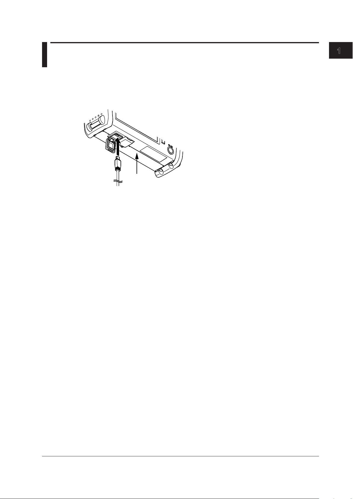
USB type B (mini B) connector
Connector used to connect the AQ1100 to the
controller (such as a PC) using a USB cable.
Chapter 1 USB Interface
1.1 Names and Functions of Parts
Front Panel
Bottom
USB Interface
IM AQ1200-17EN
1-1

1-2
IM AQ1200-17EN
1.2 USB Interface Functions and Specifications
USB Interface Functions and Specifications
Reception Function
You can specify the same settings as those specified by front panel key operations.
Receives output requests for measured data, setup data of the panel, and error codes.
Transmission Function
Outputs measured and computed data.
Outputs panel setup data and the status byte.
Outputs error codes that have occurred.
USB Interface Specifications
Electrical and mechanical specifications: Conforms to USB Rev.1.1
Connector: Type B (mini B) connector (receptacle)
Number of ports: 1
Power supply: Self-powered
Compatible PC systems: PC running Windows 2000,
Vista with a standard USB port (a separate device driver
is needed to connect to a PC).
Windows XP, or Windows
Switching between Remote and Local Modes
When Switching from Local to Remote Mode
Sending a command when the instrument is in the local mode causes the instrument to switch to the
remote mode.
• All keys except the
• Settings entered in local mode are retained even when the AQ1200 switches to remote mode.
When Switching from Remote to Local Mode
Pressing the Local soft key in remote mode puts the instrument in local mode.
• Key operations are enabled.
• Settings entered in remote mode are retained even when the AQ1200 switches to local mode.
Note
The AQ1200 cannot be remotely controlled via the USB interface while the storage function is in operation.
Remote control via the Ethernet interface is also not possible.
Local soft key are disabled.
1
1.3 Connecting via the USB Interface
Bottom
Connection Procedure
Open the bottom cover of the left side.
1.
Connect a USB cable to the type B (mini B) connector.
2.
Precautions to Be Taken When Connecting the Cable
• Connect the USB cable by inserting the connector firmly into the USB connector.
• Do not connect or disconnect the USB cable after the power is turned ON until the AQ1200 series is
ready for operation (approximately 20 s).
USB Interface
IM AQ1200-17EN
1-3

1.4 Setting the AQ1200 (USB)
Set the mode to Control I/O.
Procedure
Selecting the USB Interface Function
Press SETUP and then the System Setup soft key to display the following screen.
1.
Releasing the Remote Control
Press the Local soft key that appears on the screen after communication starts.
1.
Explanation
USB Interface
To control the AQ1200 remotely using communication commands through the USB port, install
YOKOGAWA’s TMC (Text and Measurement Class) driver into your PC. To obtain YOKOGAWA’s USB
TMC driver, contact your nearest YOKOGAWA dealer or access the following USB driver page at our
Web site and download it.
http://www.yokogawa.com/tm/tm-softdownload.htm
Note
• You cannot change the display while the AQ1200 is being remotely controlled.
• Only use the USB TMC driver (or software) provided by YOKOGAWA.
1-4
IM AQ1200-17EN
1
2
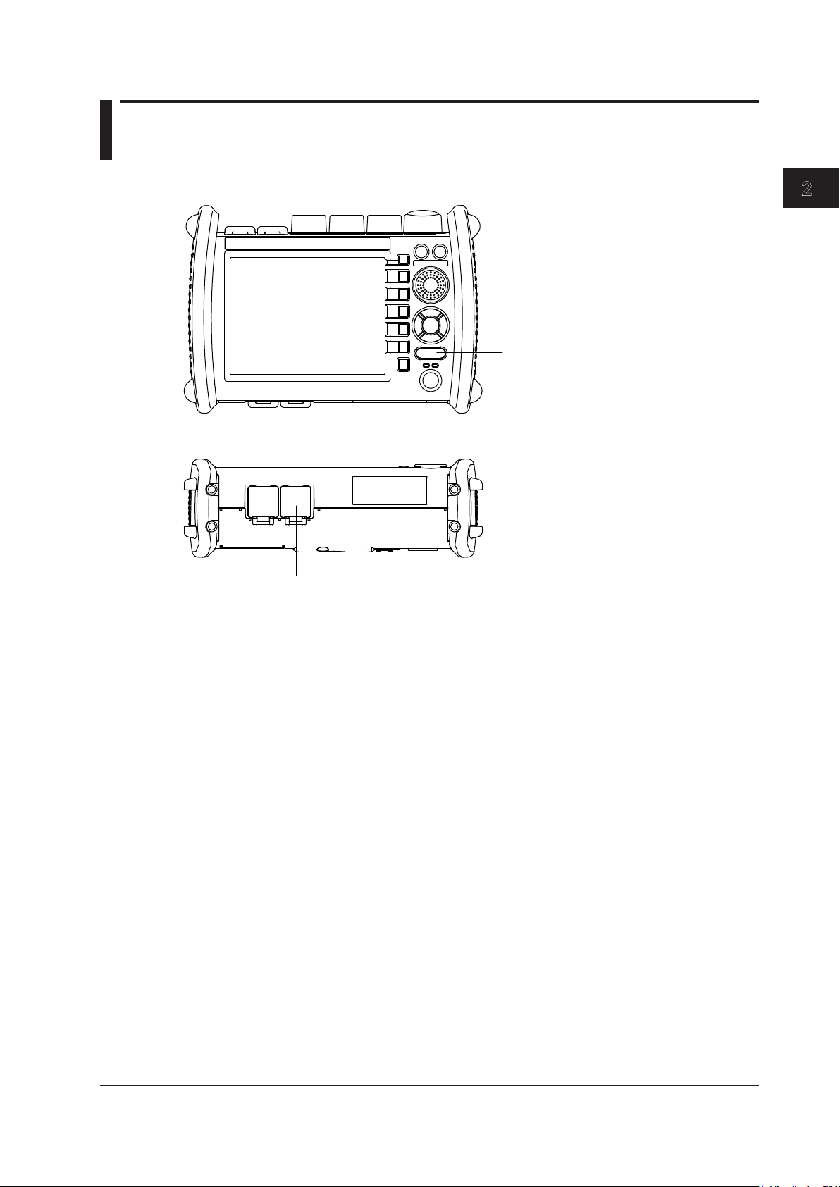
SETUP key
Press this key to select
the ethernet interface.
Ethernet Port
Connector used to connect the AQ1100 to the
controller (such as a PC) using a ethernet cable.
Chapter 2 Ethernet Interface (Option)
2.1 Names and Functions of Parts
Front Panel
Bottom
Ethernet Interface (Option)
IM AQ1200-17EN
2-1

2-2
IM AQ1200-17EN
2.2 Ethernet Interface Functions and Specifications
Ethernet Interface Features
Reception Feature
The AQ1200 reception feature allows you to specify the same settings through an Ethernet connection
that you can specify using the front panel keys.
The AQ1200 can receive output requests for measured data, panel setting data, and error codes.
Transmission Feature
The AQ1200 can transmit measured data.
The AQ1200 can transmit panel setting data and the status byte.
The AQ1200 can transmit error codes when errors occur.
Ethernet Interface Specifications
Electrical and mechanical specifications: Conforms to IEEE802.3
Transmission system: Ethernet (10BASE-T/100BASE-TX)
Data rate: 10 Mbps/100 Mbps
Number of communication ports: 1
Port number: 10001/tcp
Communication protocol: VXI-11
Connector type: RJ45 connector
Switching between Remote and Local Modes
When Switching from Local to Remote Mode
Sending a command when the instrument is in the local mode causes the instrument to switch to the
remote mode.
• All keys except the
• Settings entered in local mode are retained even when the AQ1200 switches to remote mode.
Local soft key are disabled.
When Switching from Remote to Local Mode
Pressing the Local soft key in remote mode puts the instrument in local mode.
• Key operations are enabled.
• Settings entered in remote mode are retained even when the AQ1200 to local mode.
Note
The AQ1200 cannot be remotely controlled via the USB interface while the storage function is in operation.
Remote control via the Ethernet interface is also not possible.
FTP Function
The AQ1200 series has an FTP function. You can transfer the data stored in the AQ1200 internal
memory to the PC using FTP commands from the PC.
1
2
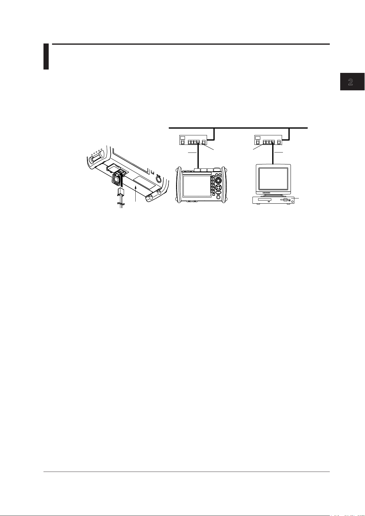
2.3 Connecting the Ethernet Interface
Network
NIC
Ethernet
PC
AQ1200
Hub or router supporting
100BASE-TX
*
*
* UTP cable or STP cable (straight cable in either case)
Bottom
Connection Procedure
Open the bottom cover of the right side.
1.
Connect a UTP (Unshielded Twisted-Pair) cable or an STP (Shielded Twisted-Pair) cable that is
2.
connected to a hub, for example, to the 100BASE-TX port on the bottom of the AQ1200.
Ethernet Interface (Option)
Precautions to Be Taken When Connecting the Cable
• Be sure to use a straight cable via a hub for the connection between the AQ1200 and the PC.
• Use a network cable that conforms to your network environment (such as the data rate).
• When using a UTP cable (straight cable), use a cable of category 5.
IM AQ1200-17EN
2-3
2-4
IM AQ1200-17EN
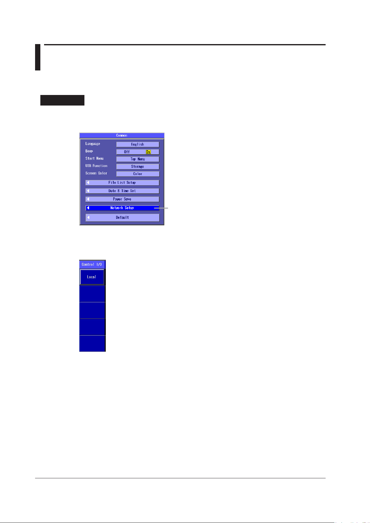
2.4 Setting the AQ1200 (Network)
Set the Ethernet Interface.
The settings for remotely controlling the AQ1200 via the Ethernet interface are explained below.
Procedure
Selecting the Ethernet Interface Function
Press SETUP and then the System Setup soft key to display the following screen.
1.
Releasing the Remote Control
Press the Local soft key that appears on the screen after communication starts.
1.

Explanation
1
2
Setting the Ethernet Interface
You must set the following parameters to use the Ethernet interface function.
•
Enabling or Disabling the Network Setup
After you have set the user name, password, timeout value, and TCP/IP parameters, select Valid
and then restart the AQ1200 to use the network connection.
•
User Name
Password
•
Setting the Timeout Value
•
The connection to the network is automatically disconnected if there is no access to the AQ1200
for the specified time.
• Setting the
IP Address
Subnet Mask
Default Gateway
For details on how to configure the settings, see section 10.4, “Configuring Network Settings (Option),”
in the AQ1200 OTDR Multi Field Tester User's Manual, IM AQ1200-01EN.
Note
• You must restart the AQ1200 if you change the Ethernet settings. Before you restart the AQ1200, the
settings from before you changed the settings are used.
• The AQ1200 cannot be remotely controlled via the ethernet interface while the USB storage function is in
operation.
TCP/IP
2.4 Setting the AQ1200 (Network)
Ethernet Interface (Option)
IM AQ1200-17EN
2-5

1
2
3
Chapter 3 Before Programming
1.&5FS.0%VMBUJPO.0%@$86/*5%#1.5
Unit
Unit
Example
1.&5FS.0%VMBUJPO.0%@$81.5
Data
Example
Header
1.&5FS.0%VMBUJPO.0%@$86/*5%#1.5
Unit
Unit
Example
1.&5FS.0%VMBUJPO.0%@$81.5&3.5
Header
Data
Example
Data
3.1 Messages
Messages
Messages are used to exchange information between
the controller and the instrument. Messages that are
sent from the controller to the instrument are called
program messages and messages that are sent
back from the instrument to the controller are called
response messages.
If a program message contains a message unit that
requests a response (a query), the instrument returns
a response message upon receiving the program
message. A single response message is always
returned in response to a single program message.
Program Messages
Program Message Unit
A program message consists of zero or more
program message units; each unit corresponds to
one command. The instrument executes the received
commands in order.
Each program message unit is separated by a
semicolon (;).
Program Data
If certain conditions are required in executing a
command, program data is added. A space (ASCII
code “20H”) separates the program data from the
header. If there are multiple sets of program data, they
are separated by commas (,). For details, see section
3.4, “Data.”
Response Messages
Response Message Units
A response message consists of one or more
response message units: each response message unit
corresponds to one response. Response message
units are delimited by a ";" (semicolon).
<RMT>
RMT stands for “response message terminator.” The
response message terminator is NL^EOM.
Before Programming
<PMT>
PMT is a program message terminator. The following
three types are available.
• NL (New Line)
Same as LF (Line Feed). ASCII code"0AH" is used.
• ^END
END message defined in IEEE488.1. (EOI signal)
(The data byte sent with an END message will be
the final item of the program message unit.)
• NL^END
NL with an END message added (NL is not included
in the program message unit.)
Program Header
A program header is used to indicate the command
type. For details, see section 3.2, “Commands.”
A response header sometimes precedes the response
data. A space separates the data from the header. For
details, see section 3.3, “Response.”
Response Data
Response data contains the content of the response.
If there are multiple sets of response data, they are
separated by commas (,). For details, see section 3.4,
“Data.”
If there are multiple queries in a program message,
responses are returned in the same order that the
queries were received in. The AQ1200 returns a single
response message unit to most queries, but there
are queries that the AQ1200 returns multiple units to.
The first response message unit always corresponds
to the first query, but the nth response unit may not
necessarily correspond to the nth query. If you want to
make sure that every response is retrieved, divide the
program messages into individual messages.
Response Header
IM AQ1200-17EN
3-1

3-2
IM AQ1200-17EN
3.1 Messages
Note
• It is always possible to send a program message if the
previous message which was sent did not contain any
queries.
• If the previous message contained a query, it is not
possible to send another program message until a
response message has been received. An error will
occur if a program message is sent before a response
message has been received in its entirety. A response
message which has not been receivedwill be discarded.
• If an attempt is made by the controller to receive
a response message, even if there it no response
message, an error will occur. An error will also occur if
the controller makes an attempt to receive a response
message before transmission of a program message has
been completed.
• If a program message of more than one unit is sent
and some of the units are incomplete, this instrument
receives program message units which the instrument
thinks complete and attempts to execute them. However,
these attempts may not always be successful and
a response may not always be returned, even if the
program message contains queries.

1
2
3
3.2 Commands
Command
There are three types of commands (program headers)
that a controller may send to the AQ1200. The
commands differ in their program header formats.
Common Command Header
Commands that are defined in IEEE 488.2-1987 are
called common commands. Be sure to include an
asterisk (*) at the beginning of a common command.
Common command example
*CLS
Compound Header
Other commands that are specific to the AQ1200 are
classified and arranged in a hierarchy according to
their functions. Be sure to use a colon to specify a
lower hierarchical level.
Compound header example
:PMETer:LINK:STATe
When Concatenating Commands
Command Groups
A command group is a group of commands that have
common compound headers arranged in a hierarchy. A
command group may contain sub-groups.
Example
Commands relating to acquisition settings
:PMETer:DREF
:PMETer:LINK:STATe
:PMETer:MAXMin:STATe
:PMETer:MODulation
:PMETer:OFFSet
:PMETer:REFerence
:PMETer:WAVelength:DETail
When Concatenating Commands of the Same
Group
The AQ1200 stores the hierarchical level of the
command that is currently being executed and
processes the next command on the assumption that
it belongs to the same level. Therefore, the common
header section can be omitted for commands that
belong to the same group.
Example
:PMETer:MODulation MOD_CW;UNIT DB<PMT>
When Concatenating Common Commands
Common commands that are defined in the IEEE
488.2-1987 are independent of hierarchy. There is no
need to use a colon.
Example
:PMETer:MODulation MOD_CW;*CLS;UNIT
DB<PMT>
When Separating Commands with <PMT>
If a terminator is used to separate two commands,each
command is a separate message. Therefore,
the common header must be typed in for each
commandeven when commands of the same command
groupare being concatenated.
Example
:PMETer:MODulation MOD_CW<PMT>:PMETer
UNIT DB<PMT>
Upper-level Query
An upper-level query is a query that is made by
appending a question mark to the highest level
command of a group. The controller can receive all
of the settings in a group collectively by executing
an upper-level query. Some upper-level queries of a
group, which may be comprised of more than three
hierarchical levels, can cause the AQ1200 to transmit
all the lower level settings.
Example
:NETWork:CONTrol?<PMT> -> :NETW:CONT:
PASS "ABC";TIM 30;USER "anonyumous"
Note
• The response to an upper-level query can be sent back
to the AQ1200 as a program message. This enables the
settings that were present when the upper-level query
was made to be reproduced later on.
• Some upper-level queries do not return setup data that is
not currently in use. Exercise caution because not all of a
group’s information is necessarily returned in a response.
Before Programming
When Concatenating Commands of Different
Groups
If the subsequent command does not belong to the same
group, place a colon in front of the header (cannot be omitted).
Example
:PMETer:MODulation MOD_CW;:MENU:
FUNCtion TOP<PMT>
IM AQ1200-17EN
3-3

3-4
IM AQ1200-17EN
3.2 Commands
Header Interpretation Rules
The AQ1200 interprets the header that it receives
according to the rules below.
Example
"
DRANge
" can be written as "
drange
" or "
Drange
• The lower-case characters can be omitted.
Example
"
DRANge
" can be written as "
DRANG
" or "
DRAN
."
• The question mark at the end of a header indicates
that it is a query. You cannot omit the question mark.
Example
The
shortest abbreviation for "
DRANge?
" is "
DRAN?
• If the <x> (value) at the end of a mnemonic is
omitted, it is interpreted as a 1.
Example
M<x>,
If you write "
M
" for "
" "M1." is specified.
Note
A mnemonic is a character string made up of
alphanumeric characters.)
."
."

1
2
3
3.3 Response
Form
When the controller sends a query with a question
mark, the AQ1200 returns a response message to the
query.
Response Consisting of a Header and Data
Responses that can be used as program messages
without any changes are returned with command
headers attached.
Example
:PMETer:MODulation?<PMT>
-> :PMETer:MODulation MOD_270HZ<RMT>
If You Want the AQ1200 to Return Responses
without Headers
You can configure the AQ1200 so that even responses
that have both headers and data are returned without
headers. Use the COMMunicate:HEADer command for
this purpose.
Abbreviated Form
The AQ1200 normally returns response headers with
the lower-case section removed. You can configure
the AQ1200 so that full headers are returned. Use the
COMMunicate:VERBose command for this purpose.
Before Programming
IM AQ1200-17EN
3-5
 Loading...