

Page 1

User's
Manual
Model AE14
Magnetic Flow Converter
[Style:S1]
IM 1E7C1-E
IM 1E7C1-E
13th Edition
Page 2

CONTENTS
Contents
1. INTRODUCTION ................................................................................................... 1-1
2. HANDLING PRECAUTIONS...............................................................................2-1
2.1 Checking Model and Specifications ................................................................ 2-1
2.2 Accessories ...................................................................................................... 2-1
2.3 Storage Precautions ......................................................................................... 2-1
2.4 Installation Location Precautions .................................................................... 2-1
3. INSTALLATION ..................................................................................................... 3-1
3.1 Installing Magnetic Flow Converter ................................................................ 3-1
3.2 Wiring Precautions .......................................................................................... 3-1
3.2.1 Protective Grounding............................................................................... 3-1
3.2.2 General Precautions ................................................................................. 3-1
3.2.3 Cable Types.............................................................................................. 3-2
3.2.4 DC Connections....................................................................................... 3-3
3.2.5 Wiring Ports............................................................................................. 3-3
3.2.6 Connecting to External Instruments ........................................................ 3-4
4. BASIC OPERATING PROCEDURES.................................................................. 4-1
4.1 Liquid Crystal Display..................................................................................... 4-1
4.2 Types of Display Data ..................................................................................... 4-2
4.2.1 Flow Rate Data Display Mode................................................................. 4-3
4.2.2 Setting Mode............................................................................................ 4-6
4.2.3 Alarm Display Mode ............................................................................... 4-9
5. FUNCTION AND DATA SETTINGS....................................................................5-1
5.1 Setting Nominal Size ...................................................................................... 5-2
5.2 Setting Flow Span............................................................................................ 5-3
5.3 Setting Meter Factor ........................................................................................ 5-6
5.4 Power Frequency (For DC version only) ......................................................... 5-7
5.5 Other Functions and Settings........................................................................... 5-7
5.5.1 Pulse Output............................................................................................. 5-7
5.5.2 Display of Internal Totalization Values.................................................... 5-9
5.5.3 Resetting for Totalization Display ......................................................... 5-10
5.5.4 Damping Time Constant........................................................................ 5-10
5.5.5 Current Output During Alarm Occurrence ............................................ 5-11
5.5.6 Reversing Flow Direction ...................................................................... 5-11
5.5.7 Limiting Current Output ........................................................................ 5-11
5.5.8 Forward and Reverse Flow Measurement ............................................. 5-13
5.5.9 Automatic Two Range Switching .......................................................... 5-14
5.5.10 Alarm Output at Low Flow Limit (Flow Switch) .................................. 5-15
5.5.11 Totalization Switch Output .................................................................... 5-16
5.5.12 Alarm Output ......................................................................................... 5-17
5.5.13 Data Setting Enable / Inhibit.................................................................. 5-17
5.5.14 Procedure of Selecting Special Application Items................................. 5-18
5.5.15 Rate Limit .............................................................................................. 5-18
5.5.16 Pulsating Flow ....................................................................................... 5-19
FD No. IM 1E7C1-E
13th Edition: Dec., 2003(YK)
All Rights Reserved, Copyright © 1994, Yokogawa Electric Corporation
i
Page 3

CONTENTS
6. OPERATION VIA BRAIN TERMINAL .............................................................. 6-1
6.1 Operation Via the BT200 ................................................................................. 6-1
6.1.1 BT200 Connections ................................................................................. 6-1
6.1.2 BT200 Keypad Layout............................................................................. 6-2
6.1.3 Major BT200 Key Functions ................................................................... 6-3
6.1.4 Displaying Flow Rate Data...................................................................... 6-5
6.2 Setting Parameters ........................................................................................... 6-6
6.2.1 Setting Nominal Size ............................................................................... 6-6
6.2.2 Setting Flow Span Via the BT200............................................................ 6-7
6.2.3 Setting Meter Factor ................................................................................ 6-8
6.2.4 Power Frequency ..................................................................................... 6-9
6.2.5 Pulse Output (Refer to 5.5.1) ................................................................... 6-9
6.2.6 Display of Internal Totalization Values (Refer to 5.5.2) ........................ 6-10
6.2.7 Resetting for Totalization Display (Refer to 5.5.3) ............................... 6-10
6.2.8 Damping Time Constant (Refer to 5.5.4) .............................................. 6-11
6.2.9 Current Output during Alarm Occurrence (Refer to 5.5.5) ................... 6-11
6.2.10 Reversing Flow Direction(Refer to 5.5.6) ............................................. 6-11
6.2.11 Limiting Current Output (Refer to 5.5.7) .............................................. 6-11
6.2.12 Forward and Reverse Flow Measurement (Refer to 5.5.8) .................... 6-12
6.2.13 Automatic Two Range Switching (Refer to 5.5.9) ................................ 6-13
6.2.14 Alarm Output at Low Flow Limits (Flow Switch) (Refer to 5.5.10) ..... 6-13
6.2.15 Totalization Switch Output (Refer to 5.5.11) ........................................ 6-14
6.2.16 Alarm Output (Refer to 5.5.12) ............................................................. 6-14
6.2.17 Data Setting Enable / Inhibit (Refer to 5.5.13)...................................... 6-15
6.2.18 Procedure of Selecting Special Application Items (Refer to 5.5.14) ..... 6-15
6.2.19 Rate Limit (Refer to 5.5.15) .................................................................. 6-15
6.2.20 Pulsating Flow (Refer to 5.5.16)............................................................ 6-15
6.2.21 User-Defined Units Via the BT200........................................................ 6-16
6.2.22 Other Important Points to Note.............................................................. 6-17
7. ACTUAL OPERATION.......................................................................................... 7-1
7.1 Pre-Operation Zero Adjustment....................................................................... 7-1
7.1.1 Zero Adjustment Using Data Setting Keys .............................................. 7-1
7.1.2 Zero Adjustment Via the BT200.............................................................. 7-2
7.2 Self-diagnostics Functions............................................................................... 7-3
7.2.1 Display and Output Status during Alarm Occurrence ............................. 7-3
7.2.2 Error Description and Countermeasures.................................................. 7-3
8. MAINTENANCE .................................................................................................... 8-1
8.1 Loop Test (Test Output)................................................................................... 8-1
8.1.1 Settings for Test Output Using Data Setting Keys................................... 8-1
8.1.2 Setting for Test Output Via the BT200 .................................................... 8-1
8.2 Fuse Replacement............................................................................................ 8-2
8.3 Trouble Shooting ............................................................................................. 8-2
9. OUTLINE................................................................................................................. 9-1
10. PARAMETER SUMMARY ................................................................................. 10-1
ii
IM 1E7C1 -E
Page 4

CONTENTS
11. EXPLOSION PROTECTED TYPE INSTRUMENT ........................................ 11-1
11.1 ATEX Directive ............................................................................................. 11-1
11.2 FM ................................................................................................................. 11-2
11.3 CSA ............................................................................................................... 11-2
11.4 SAA ............................................................................................................... 11-3
iii
IM 1E7C1 -E
Page 5

1. INTRODUCTION
NOTE
1. INTRODUCTION
This instrument has been already adjusted at the
factory before shipment.
To ensure correct use of the instrument, please read
this manual thoroughly and fully understand how to
operate the instrument before operating it.
Regarding This Manual
•This manual should be passed on to the end user.
• Before use, read this manual thoroughly to comprehend its contents.
• The contents of this manual may be changed
without prior notice.
• All rights reserved. No part of this manual may be
reproduced in any form without Yokogawa’s written
permission.
•Yokogawa makes no warranty of any kind with
regard to this material, including, but not limited to,
implied warranties of merchantability and suitability
for a particular purpose.
• All reasonable effort has been made to ensure the
accuracy of the contents of this manual. However, if
any errors are found, please inform Yokogawa.
• Yokogawa assumes no responsibilities for this
product except as stated in the warranty.
• If the customer or any third party is harmed by the
use of this product, Yokogawa assumes no responsibility for any such harm owing to any defects in the
product which were not predictable, or for any
indirect damages.
The following safety symbol marks are used in
this manual and instrument;
WARNING
A WARNING sign denotes a hazard. It calls
attention to procedure, practice, condition or the
like, which, if not correctly performed or adhered
to, could result in injury or death of personnel.
CAUTION
A CAUTION sign denotes a hazard. It calls
attention to procedure, practice, condition or the
like, which, if not correctly performed or adhered
to, could result in damage to or destruction of
part or all of the product.
IMPORTANT
A IMPORTANT sign denotes an attention to
avoid leading to damage to instrument or system
failure.
Safety Precautions
• The following general safety precautions must be
observed during all phases of operation, service, and
repair of this instrument. Failure to comply with
these precautions or with specific WARNINGS
given elsewhere in this manual violates safety
standards of design, manufacture, and intended use
of the instrument. YOKOGAWA Electric Corporation assumes no liability for the customer’s failure to
comply with these requirements. If this instrument is
used in a manner not specified in this manual, the
protection provided by this instrument may be
impaired.
A NOTE sign denotes a information for essential
understanding of the operation and features.
Protective grounding terminal.
Function grounding terminal. This terminal
should not be used as a “Protective grounding
terminal”.
Alternating current.
Direct current.
1-1
IM 1E7C1-E
Page 6

1. INTRODUCTION
Warranty
• The guaranteed term of this instrument is described
in the quotation. We repair the damages that
occurred during the guaranteed term for free.
• Please contact with our sales office when this
instrument is damaged.
• If the instrument has trouble, please inform us
model code, serial number, and concrete substances
or situations. It is preferable to be attached a outline
or data.
• We decide after the examination if free repair is
available or not.
• Please consent to the followings for causes of
damages that are not available as free repair, even if
it occured during the guaranteed term.
A:Unsuitable or insufficient maintenance by the
customer.
B: The handling, using, or storage that ignore the
design and specifications of the instrument.
C: Unsuitable location that ignore the description in
this manual.
D:Remaking or repair by a person except whom we
entrust.
E: Unsuitable removing after delivered.
F: A natural disaster (ex. a fire, earthquake, storm and
flood, thunderbolt) and external causes
For Safety Using
For safety using the instrument, please give attention
mentioned below.
WARNING
(1) Installation
• The instrument must be installed by expert
engineer or skilled personnel. The procedures
described about INSTALLATION are not
permitted for operators.
• The Magnetic Flowmeter is a heavy instrument.
Please give attention to prevent that persons
are injured by carrying or installing. It is preferable for carrying the instrument to use a cart
and be done by two or more persons.
• In case of high process temperature, care
should be taken not to burn yourself because
the surface of body and case reach a high
temperature.
• When removing the instrument from hazardous
processes, avoid contact with the fluid and the
interior of the flow tube.
• All installation shall comply with local installation requirement and local electrical code
(2) Wiring
• The instrument must be installed by expert
engineer or skilled personnel. The procedures
described about WIRING are not permitted for
operators.
•Please confirm voltages between the power
supply and the instrument before connecting
the power cables. And also, please confirm
that the cables are not powered before connecting.
• The protective grounding must be connected to
the terminal in order to avoid personal shock
hazard.
(3) Operation
• Wait 10 min. after power is turned off, before
opening the covers.
(4) Maintenance
•Please do not carry out except being written to
a maintenance descriptions. When these
procedures are needed, please contact to
nearest YOKOGAWA office.
• Care should be taken to prevent the build up of
drift, dust or other material on the display glass
and data plate. In case of its maintenance, soft
and dry cloth is used.
(5) Explosion Protected Type Instrument
• For explosion proof type instrument, the
description in Chapter 11 “EXPLOSION
PROTECTED TYPE INSTRUMENT” is prior to
the other description in this user's manual.
• Only trained persons use this instrument in the
industiral location.
• The protective grounding must be connected
to a suitable IS grounding system.
• Take care not to generate mechanical spark
when access to the instrument and peripheral
devices in hazardous locations.
1-2
IM 1E7C1-E
Page 7

1. INTRODUCTION
ATEX Documentation
This procedure is only applicable to the countries in
European Union.
GB
All instruction manuals for ATEX Ex related products
are available in English, German and French. Should
you require Ex related instructions in your local
language, you are to contact your nearest Yokogawa
office or representative.
DK
Alle brugervejledninger for produkter relateret til
ATEX Ex er tilgængelige på engelsk, tysk og fransk.
Skulle De ønske yderligere oplysninger om håndtering
af Ex produkter på eget sprog, kan De rette
henvendelse herom til den nærmeste Yokogawa
afdeling eller forhandler.
I
Tutti i manuali operativi di prodotti ATEX
contrassegnati con Ex sono disponibili in inglese,
tedesco e francese. Se si desidera ricevere i manuali
operativi di prodotti Ex in lingua locale, mettersi in
contatto con l’ufficio Yokogawa più vicino o con un
rappresentante.
E
Todos los manuales de instrucciones para los productos
antiexplosivos de ATEX están disponibles en inglés,
alemán y francés. Si desea solicitar las instrucciones de
estos artículos antiexplosivos en su idioma local,
deberá ponerse en contacto con la oficina o el
representante de Yokogawa más cercano.
NL
Alle handleidingen voor producten die te maken
hebben met ATEX explosiebeveiliging (Ex) zijn
verkrijgbaar in het Engels, Duits en Frans. Neem,
indien u aanwijzingen op het gebied van
explosiebeveiliging nodig hebt in uw eigen taal, contact
op met de dichtstbijzijnde vestiging van Yokogawa of
met een vertegenwoordiger.
SF
Kaikkien ATEX Ex -tyyppisten tuotteiden käyttöhjeet
ovat saatavilla englannin-, saksan- ja ranskankielisinä.
Mikäli tarvitsette Ex -tyyppisten tuotteiden ohjeita
omalla paikallisella kielellännne, ottakaa yhteyttä
lähimpään Yokogawa-toimistoon tai -edustajaan.
P
Todos os manuais de instruções referentes aos produtos
Ex da ATEX estão disponíveis em Inglês, Alemão e
Francês. Se necessitar de instruções na sua língua
relacionadas com produtos Ex, deverá entrar em
contacto com a delegação mais próxima ou com um
representante da Yokogawa.
F
Tous les manuels d’instruction des produits ATEX Ex
sont disponibles en langue anglaise, allemande et
française. Si vous nécessitez des instructions relatives
aux produits Ex dans votre langue, veuillez bien
contacter votre représentant Yokogawa le plus proche.
D
Alle Betriebsanleitungen für ATEX Ex bezogene
Produkte stehen in den Sprachen Englisch, Deutsch
und Französisch zur Verfügung. Sollten Sie die
Betriebsanleitungen für Ex-Produkte in Ihrer
Landessprache benötigen, setzen Sie sich bitte mit
Ihrem örtlichen Yokogawa-Vertreter in Verbindung.
S
Alla instruktionsböcker för ATEX Ex (explosionssäkra)
produkter är tillgängliga på engelska, tyska och
franska. Om Ni behöver instruktioner för dessa
explosionssäkra produkter på annat språk, skall Ni
kontakta närmaste Yokogawakontor eller representant.
GR
ATEX Ex
, .
Ex
Yokogawa .
1-3
IM 1E7C1-E
Page 8

2. HANDLING PRECAUTIONS
2. HANDLING PRECAUTIONS
This instrument has been already tested thoroughly at
the factory. When the instrument is delivered, please
check externals and make sure that no damage
occurred during transportation.
In this chapter, handling precautions are described.
Please read this chapter thoroughly at first. And please
refer to the relative matter about other ones.
If you have any problems or questions, please make
contact with Yokogawa sales office.
2.1 Checking Model and Specifications
The model and specifications are shown on the Data
Plate. Please confirm the specifications between the
instrument that was delivered and the purchase order
(refer to the chapter 10. Outline).
Please let us know Model and Serial No. when making
contact with Yokogawa sales office.
• Plug (for DC power supply only) : 1-piece
• Hexagonal wrench : 1-piece
(for special screw of hazardous duty type converter.)
2.3 Storage Precautions
In case the instrument is expected to be stored over a
long term, please give attention to the followings;
• The instrument should be stored in its original
packing condition.
• The storage location should be selected according to
the following conditions:
1) The location where it is not exposed to rain or
water.
2) The location where there is few vibration or
shock.
3) Temperature and humidity should be:
Temperature: –20 to 60˚C (–4 to 140˚F)
Humidity: 5 to 80% RH (no condensation)
Preferable ambient temperature and humidity
are 25˚C(77˚F) and about 65% RH.
MAGNETIC FLOW
CONVERTER
MODEL
SUFFIX
STYLE
SUPPLY
CURRENT
OUTPUT
PULSE
OUTPUT
AMB.TEMP.
NO.
Figure 2.1 Data Plate
V AC~47–63Hz 36VA 12.5W
V DC 12.5W
4 - 20mA
(0 - 750Ω)
30V DC 0.2 Amax
–20~60 °C
Made in Japan
N200
2.2 Accessories
When the instrument is delivered, please make sure
that the following accessories are in the package.
Spare fuse can be applied only to this product.
• Fuse (250V,2A time lag) : 1-piece
*The spare fuse is taped to the converter.
•Mounting hardware
•Data sheet : 1-sheet
• Unit labels : 1-sheet
2.4 Installation Location Precautions
Please select the installation location considering the
following items to ensure long term stable operation of
the flow tube.
• Ambient Temperature:
Please avoid to install the instrument at the location
where temperature changes continuously. If the
location receives radiant heat from the plant, provide
heat insulation or improve ventilation.
•Atmospheric Condition:
Please avoid to install the instrument in an corrosive
atmosphere. In case of installing in the corrosive
atmosphere, please keep ventilating sufficiently and
prevent rain from entering the conduit.
•Vibration or shock:
Please avoid to install the instrument at the location
where there is heavy vibration or shock.
2-1
IM 1E7C1-E
Page 9

3. INSTALLATION
3. INSTALLATION
WARNING
This instrument must be installed by expert
engineer or skilled personnel. The procedures
described in this chapter are not permitted for
operators.
3.1 Installing Magnetic Flow Converter
A signal cable (AM011) is used between the remote
type flow tube and the converter. The maximum signal
cable length is 30m (98ft).
The converter is mounted on a 2 inch (60.5mm outer
dia.) vertical or horizontal pipe. See Figure 3.1.1
Vertical Mounting
2-inch pipe
U-Bolt
3.2 Wiring Precautions
CAUTION
Please confirm that all conncetions are correct
before applying power to the instrument.
Improper wiring may damage the flowmeter.
The external signal wirings are connected into the
terminal inside the converter. Please connect to each
terminal (Please refer to Figure 3.2.1) by taking off a
cover backside the converter.
Excitation Cable
Dedicated Cable
AM011-4
A
B
C
Converter AE14
Converter
Terminals
A
B
C
(See NOTE below)
(See NOTE below)
SA
EX2
EX1
SB
Ex1
Ex2
NOTE : Terminate those shielding wire
terminals using tape.
Power supply
Protective ground
4 to 20 mA DC output
Pulse or alarm output
Flow Tube
AE***D
A
B
C
Ex1
Ex2
Bracket
Horizontal Mounting
Nut
Bracket
2-inch pipe
Figure 3.1.1 Magnetic Flow Converter Installation
Nut
U-Bolt
Figure 3.2.1 Wiring
3.2.1 Protective Grounding
CAUTION
Please be sure to connect protective grounding
of ADMAG AE with cable of 2mm2 or larger
cross section in order to avoid the electrical
shock to the operators and maintenance engineers and prevent the influence of external
noise. And further connect the grounding wire to
the mark (100Ω or less).
3.2.2 General Precautions
Please give attention to the followings in wiring.
3-1
IM 1E7C1-E
Page 10

3. INSTALLATION
NOTE
CAUTION
• Please pay attention to avoid the cable is
bended excessively.
• Please do not connect cables outdoors in case
of rain to prevent damages from dew formation
and to keep insulation inside the terminal box
of the flowmeter.
• The all cable ends are to be provided with
round crimp-on terminal.
•The power cables and signal cables must be
routed in separate steel conduit tubes or
flexible tubes.(except 4-core 24VDC cable
wiring.)
• When waterproof glands, union equipped
waterproof glands are used, the glands must be
properly tightened to keep the box watertight.
•Please install a external switch or circuit
breaker as a means of power off (capacitance;
15A, conform to IEC947-1 and IEC947-3). The
preferable location is either near the instrument
or other places to easy operation. Furthermore, please indicate "power off equipment" on
the those external switch or circuit breaker.
•Please be sure to fully tighten the terminal box
cover before the power is turned on.
•Please be sure to turn off the power before
opening the terminal box cover.
• In case of DC power supply, a plug is attached.
When 4-core cable is used, please put that
plug into unused electrical connection port.
3.2.3 Cable Types
(1) Dedicated Signal Cable(AM011)
The flow signal is transmitted via this dedicated cable.
The cable is constructed with double shielding over the
two conductors, and used heat-resistant vinyl as the
outer jacket material.
IMPORTANT
If the cable is longer than required, cut off any
extra length, rather coiling it up, and terminate
the conductors as shown in Figure 3.2.3. Avoid
using intermediate terminal boards to extend the
cable length, or this will interrupt the shielding.
ACB
SA
On the converter
Figure 3.2.3 Treatment of Dedicated Signal Cable
25 (0.98)
(WHITE) (BLACK) (RED)
side
150
(5.9)
SB
50 (1.97)
8 (0.3) Max.
20 (0.8)
70 (2.76)
80 (3.15)
L (SPECIFIED LENGTH)
AM011*A
ACB
55 (2.2)
90 (3.5)
(WHITE) (BLACK) (RED)
8 (0.3) Max.
150
(5.9)
On the flow tube
ø10.5 (0.4)
F030203.EPS
CAUTION
Since A, B, SA, SB, and C all operate at different electrical potentials, securely insulate them
from each other so they do not touch.
The shields must not be allowed to touch each
other or to touch the case.
Cover each shield with vinyl tube or wrap in vinyl
tape.
90 (3.5)
side
Finished diameter: 10.5 mm (0.413”)
Maximum length: 30 m (98 ft)
Maximum temperature: 80°C (176°F)
Figure 3.2.2 Dedicated Signal Cable AM011
Conductors A and B carry the signal from the
electrodes, and C is at the potentials of the liquid
it self (signal common) . Shields SA and SB are
kept at the same potentials as the individual
electrodes (these are actively driven shields).
This is done to reduce the effect of the distributed capacitance of the cable at long cable
length. Note that, since the signals from the
individual electrodes are impedance converted
inside the converter, errors will result if they
come in contact with any other component.
Great care must be taken in the cable end
treatment.
3-2
IM 1E7C1-E
Page 11

3. INSTALLATION
(2) Power, Excitation, or Output Cable
Power Cable
• Crimp-on Terminal
• Green/Yellow covered conductors shall be used only
for connection to PROTECTIVE CONDUCTOR
TERMINALS.
• Conform to IEC277 or IEC245 or equivalent
national authorization.
Excitation or Output Cable
•Please use Polyvinyl chloride insulated and sheathed
control cables (JIS C3401) or Polyvinyl chloride
insulated and sheathed portable power cables (JIS
C3312) or equivalents.
Outer Diameter
• 6.5 to 12mm in diameter (10.5 to 11.5 mm for
waterproof gland / ECG, /ECU)
Nominal Cross Section
•Single wire; 0.5 to 2.5mm2 , Stranded wire; 0.5 to
2
2.5mm
EX1
EX2
(2.4)
60
85
(3.3)
EX1
Unit: mm (inch)
EX2
Supply Voltage and Cable Length
20
22
24
Usable range E(V)
26
2
28
Cable cross section area : 2mm
Allowed
cable
length
m(ft)
1000
(3300)
900
(2970)
800
(2640)
700
(2310)
600
(1980)
500
(1650)
400
(1320)
300
(990)
200
(660)
100
(330)
0
Cable cross section area : 1.25mm
(3)Setting Power Supply Frequency
IMPORTANT
In case of DC power supply, the frequency of
the power supply has to be adjusted. Please
adjust for the local power frequency. The power
supply frequency is set in parameter B12 (or
Power freq for HART). Refer to 5.4 or 6.2.4 for
data setting procedure.
3.2.5 Wiring Ports
2
On the converter side On the flow tube side
Figure 3.2.4 End Treatment of Excitation Cable
3.2.4 DC Connections
(1)Connecting Power Supply
IMPORTANT
In case of 24VDC power supply, AC power
supplies or reversed polarities cannot be connected. It will cause the fuse to burn out.
(2)Supplied Voltage Rating for 24VDC
IMPORTANT
In case of 24VDC power supply, the specification for the supply voltage is 24VDC (-15 to
+20%), but the input voltage of the converter
drops due to cable resistance so it should be
used within the following range.
Please select the most suitable standard of wiring
procedure for the wiring ports by customer’s own.
(1)Using the Waterproof Gland
IMPORTANT
To prevent water or condensate from entering
the converter housing, waterproof glands are
recommended. Do not over-tighten the glands or
damage to the cables may result. Tightness of
the gland can be checked by confirming that the
cable is held firmly in place.
Waterproof gland
Optional specification
cade : / ECG
Gasket
Tightening gland
Figure 3.2.5 Waterproof Gland
Waterproof gland with union
joint Optional specification
cade : / ECU
JIS G 1/2
Washer
Tightening gland
JIS G 1/2
Gasket
3-3
IM 1E7C1-E
Page 12

3. INSTALLATION
(2)Conduit Wiring
In case of conduit wiring, please use the waterproof
gland to prevent water flowing through the conduit
pipe into the wiring connection.
Please slope the conduit pipe down, and install a drain
valve at the low end of the vertical pipe.
Please open the drain valve regularly.
Figure 3.2.6 Conduit Wiring
3.2.6 Connecting to External Instru-
ments
CAUTION
All the devices to be connected to current
output and pulse output must be conformed to
CSA1010, CSA950, or IEC950.
• In case of input impedance of electric counter is
large inductive noise from power supply bring
bad influence to measurement. To calculate
correctly, it is recommended to use shield cable
or to make input impedance small enough within
the limits of pulse output of flowmeter.
AE 14
PULSE OUT
AE 14
PULSE OUT
Figure 3.2.8 Pulse Output Connection
P +
P –
P +
P –
30 V DC, 0.2A. max
Protective diode
Mechanical counter
Load
Electronic counter or Universal counter
(3)Alarm Output
IMPORTANT
This is a transistor contact(insulated type) so
attention must be paid to voltage and polarity
when making connections.
This output can not switch an AC load. To do
this, another relay (see the figure below) is
required.
* The alarm output works from "close"(Normal) to
"open"(Alarm).
(1)Analog Signal Output(4 to 20mADC)
I +
AE 14
I –
Figure 3.2.7 Connection for Analog Singal Output
Receiving instrument
Load resistance max 750Ω
(max.600Ω for BRAIN Communication)
(2)Pulse Output
IMPORTANT
Please give attention to voltage and polarity in
wiring, because it is transister contact (insulation type).
•In case of the filtering constant of Electric
Counter is more than the pulse width, it makes
signal decreases and can not be calculated
correctly.
AE 14
AE 14
Figure 3.2.9 Contact Output Connection
P+
Load
P–
This connection cannot be made.
P+
External
P–
Power supply
30 V DC, 0.2A. max
3-4
Protective diode
Magnetic
AC power supply
valve
IM 1E7C1-E
Page 13

4. BASIC OPERATING PROCEDURES
4. BASIC OPERATING PROCEDURES
All data settings can be performed with the three keys on the front panel (SET, SHIFT and
INC) or using a handheld BRAIN (BT) terminal.
The following sections describe basic data configurations and how to use the three panel
keys. (See chapter 6 for information on BT operations.)
4.1 Liquid Crystal Display
Figure 4.1 shows the configuration of the ADMAG AE display panel (if equipped).
(The figure shows display when fully lit)
(1) LED (red)
Normal operation : off
During alarm: flashes
(2) Delimiter
(4) Unit Label Location
(5) Data Display
(6) Decimal Points
(7) Setting Keys
(3) Unit Display
Units displayed:
l : liter
gal : gallon
3
: cubic meters
m
/h: hour
/m: minute
If other units are to be used,
attach labels giving the specific unit.
l gal m3 /h /m
SET
SHIFT
%
INC
Figure 4.1 Configuration of Display
(1) LED (red) : This LED is off during normal operation and flashes when an
alarm condition has occurred.
(2) Delimiter : The delimiter " : " (colon) indicates that the displayed data is in
setting mode.
(3) Unit Display : Displays flow rate units. In order to display other units, the
required unit label should be selected from the provided data
sheets and attached as shown.
(4) Unit Label Location : To display units not on the LCD, select the required label from
the provided data sheets and attach it here.
(5) Data Display : Displays flow rate data, setting data and type of alarm gener-
ated.
(6) Decimal Point : Displays decimal point in the data.
(7) Setting Keys : These keys are used to change flow rate data displays and type
of setting data.
4-1
IM 1E7C1-E
Page 14

4.2 Types of Display Data
Three major types of data are displayed.
4. BASIC OPERATING PROCEDURES
1. Flow Rate Data
Display Mode
This mode displays flow
rates and totalization date.
Go to the setting mode
and use parameter "d1" to
change display items.
This mode can be called up by
pressing "SET" key while
pressing "SHIFT" key when
setting mode is displayed.
Display Example)
%
(Flow rate %)
3
m
/h
(Actual flow rate)
(Flow rate totalization value)
(Alternate display of
flow rate % and flow
rate totalization value)
(Alternate display of
actual flow rate and flow
rate totalization value)
2. Setting Mode
This mode is used to check
parameter content and
rewrite data. This mode
can be called up from the
flow rate data display mode by
pressing the "SET" key.
Display Example)
(Data item 02: 3 sec.dumping)
(Data item 03: Span 50.0)
(Data item C1: Zero adjust not possible)
(Data item d1: Selection of display items)
3. Alarm Display Mode
When an alarm situation
occurs, this mode will
replace the current mode
(flow rate or setting mode)
to show what type of
alarm has occurred.
Display Example)
(Error 07: Coil open)
(Error 06: Input signal error)
(Error 08: Incorrect span setting)
(Error 20: Metering tube not
filled with water)
(Alternate display of
actual flow rate and
flow rate %)
(Data item E1: Selection of totalization units)
4-2
IM 1E7C1-E
Page 15

4.2.1 Flow Rate Data Display Mode
• The flow rate data display mode indicates instantaneous flow and totalized flow
values.
The ADMAG AE can display 12 types of flow rate data.
• This functions can be set in the parameter "d1" key of the flow converter.
• For changing from setting mode to flow rate data display mode, press "SET" key
while pressing "SHIFT" key.
•When a BT is used, call up the "D01 DISP SELECT" parameter to select functions.
4. BASIC OPERATING PROCEDURES
Display item Content
Forward
Flow Rate %
Actual forward
Flow Rate
Forward flowrate
totalization values
Reverse flowrate
totalization values
Differential
Between the
forward and
reverse
totalization
values
Forward flowrate
( %) and Forward
totalization values
Instantaneous flow rate is displayed within a
range of -8.0(-108.0) to 108 for the span.
The actual meter rate of instantaneous flow rate
is displayed. (See note 1.)
The decimal place is the same as for the span
setting. However,since a decimal point set at the
most significant bit cannot be displayed.
It is automatically shifted 1 digit to the right. (BT setting
of 0.0001 is displayed as 0.000 on the ADMAG.)
Display forward flow rate totalization value
Display reverse flow rate totalization value
Differential totalization, between forward
totalization and reverse totalization,
is displayed.
Display alternately between display of
"RATE(%)" and "FOR. TTL"
every 4 second interval.
ADMAG AE Setting
BT Setting
D01 : DISP SELECT
RATE(%)
D01 : DISP SELECT
RATE
D01 : DISP SELECT
FOR.TOTAL
D01 : DISP SELECT
REV.TOTAL
D01 : DISP SELECT
DIF. TOTAL
D01 : DISP SELECT
RATE%/FOR.TTL
Note 1 : The LCD can display the following combination of units (by selecting a parameter)
Units other than those shown below can be displayed by attaching the provided unit labels .
l (liters) /h, l (liters) /m, m3/h, m3/m, gal/h, gal/m
4-3
IM 1E7C1-E
Page 16

4. BASIC OPERATING PROCEDURES
Display item Content ADMAG AE Setting BT Setting
Alternate
display of actual
forward
flowrate and
flowrate
totalization
values
Alternate
display of actual
forward
flowrate and
forward
flowrate (%)
Alternate
display
of forward
flowrate (%)
and reverse
totalization
values
Alternate
display of
forward
flowrate and
reverse flowrate
totalization
values
Alternate display
of forward
flowrate (%) and
differential between
the forward
and reverse
totalization values
Display alternately between
display of "RATE" and "FOR.
TTL" every 4 second interval.
Display alternately between
display of "RATE" and "RATE(%)"
every 4 second interval.
Display alternately between
display of "RATE(%)" and "REV.
TTL" every 4 second interval.
Display alternately between
display of "RATE" and "REV.
TTL" every 4 second interval.
Display alternately between
display of "RATE(%)" and "DIF.
TTL" every 4 second interval.
D01 : DISP SELECT
RATE/FOR.TTL
D01 : DISP SELECT
RATE/RATE(%)
D01 : DISP SELECT
RATE(%)/REV.TTL
D01 : DISP SELECT
RATE/REV.TTL
D01 : DISP SELECT
RATE(%)/DIF.TTL
Alternate display
of forward
flowrate and
differential between
the forward
and reverse
totalization values
Display alternately between
display of "RATE" and "DIF.
TTL" every 4 second interval.
D01 : DISP SELECT
RATE/DIF.TTL
4-4
IM 1E7C1-E
Page 17

(1) Changes in Flow Data Display Items
•Shows how the display changes when the flow converter switches are pressed.
• See chapter 6 for information on changes using the BT200.
%
SET SHIFT INC SET SHIFT INC SET SHIFT INC
4. BASIC OPERATING PROCEDURES
The display shown when the
power is turned on.
Selection
00 : Instantaneous flow rates (%)
01 : Instantaneous flow rates (actual
meter values)
02 : Forward flowrate totalization values
03 : Reverse flowrate totalization values
04 : Differetial Between the forward and
reverse totalization values
05 : Alternate display of forward flowrate
% and forward flowrate totalization
values
06 : Alternate display of forward flowrate
and flowrate totalization values
07 : Alternate display of forward flowrate
and forward flowrate (%)
08 : Alternate display of forward flowrate
(%) and reverse totalization values
09 : Alternate display of forward flowrate
and reverse flowrate totalization
values
10 : Alternate display of forward flowrate
(%) and differential between the
forward and reverse totalization
values
11 : Alternate display of forward flowrate
and differential between the forward
and reverse totalization values
Press the SET key to go to the
data mode shown above.
SET SHIFT INC SET SHIFT INC
Press the INC key to select
the number of the desired display
type.
SET SHIFT INC SET SHIFT INC
Press the SET key once and all
data starts to flash.
Press the INC key twice to
display d1:00.
Press the SET key to move the
hached portion (flashes)
to the last digit.
Wait 2 to 3 seconds and press the
SET key again to return the hatched
portion to its original position.
4-5
%
SET SHIFT INC
When all setting have been made,
hold down the SHIFT key while
pressing the SET key to return to
original display mode.
IM 1E7C1-E
Page 18

4.2.2 Setting Mode
• The setting mode is used for checking parameters and rewriting data.
• The following is an overview of the setting mode. See Section 5 "Function and Data
Settings" for detailed information.
(1) Structure of Setting Mode Display
• The display consists of two areas ; two digits to the left of the colon and four digits to
the right of it.
• Two types of data can be entered : direct entry of numerals and entry of desired data
items using codes.
Refer to "Parameter list" in chapter 11 for information on how to change settings.
Parameter number Data number
(2) Procedures for Setting and Changing Data
Example of parameter change : Changing the span (number 03) from 1.000 to 1.200
Item Display Content
4. BASIC OPERATING PROCEDURES
① Switch to
"Setting Mode"
② Parameter
Selection
➂ Data Rewrite
SET SHIFT INC
SET SHIFT INC
SET SHIFT INC
SET SHIFT INC
SET SHIFT INC
Press the SET key to go from the flow rate data display to the
setting mode.The delimiter ":" is displayed to indicate that the
mode has been swiched.
Press the SHIFT key to move the flashing segment (the selected
item)
Use the INC key to change the items displayed in the flashing
segment(the selected item).
Parameter 03 contains 5-digit data which cannot be
*
displayed as shown on the left but has to be scrolled.
Use the SET key to move the flashing segment (the selected item)
to the most significant location of the data area.
Use the SHIFT key to move the flashing segment (the selected
item) within the data area.
---Continued---
SET SHIFT INC
Use the INC key to change the data area (numeric data) in the
flashing segment (the selected item).
4-6
IM 1E7C1-E
Page 19

4. BASIC OPERATING PROCEDURES
Item Display Content
➃ Data Input
SET SHIFT INC
First time
SET SHIFT INC
Second time
➄ Switching to Flow
Data Entry
SET SHIFT INC
(3) Procedures for Changing Decimal Place
Before starting this procedure check in the data list if the position of the decimal point
for the desired parameter decimal places can be changed.
Example of parameter change : Changing the span from 1.000 to 10.00
Press the SET key twice to enter data.
(All data will start flashing when the key is pressed the first time.
Then wait 2 to 3 seconds before pressing the key the second time.)
Hold down the SHIFT key and press the SET key to switch to
the flow rate data display.
%
Item Display Content
① Selecting
Decimal
Position
➁ Moving
Decimal
Portion
➂ Data Entry
Press the SHIFT key to move the flashing segment to the decimal
point.
SET SHIFT INC
Press the INC key to move the decimal point to the right.
SET SHIFT INC
Press the SET key twice to enter data.
(All data will start flashing when the key is pressed the first time.
Then wait 2 to 3 seconds before pressing the key the second tme.)
SET SHIFT INC
First time
SET SHIFT INC
Second time
4-7
IM 1E7C1-E
Page 20

(4) Display of 5-digit Data
• The data display area has four digits and
•When the flashing segment is aligned with
can therefore not display span and other 5digit data parameters.
To display such data, the data is automatically shifted (scrolled) to the left one digit
at a time .
When a 5-digit parameter is selected, the
delimiter " : " starts to flash.
the last digit and the data includes a space,
the data is displayed as shown ④ on the
right.
4. BASIC OPERATING PROCEDURES
Display example : Display of span 123.45
①
3 seconds
➁
➂
➃
(Space)
1 second
1 second
(Space)
1 second
(5) Display of 6-digit Data
• The data display area has four digits and can therefore not display span and other 6digit data parameters. (E05 TL SET VALUE is the only 6-digit parameter.)
Like 5-digit data, 6-digit data is displayed by automatically shifting (scrolling) it to
the left one digit at a time.
(6) Display and Setting Coded Data
• Example of change : Changing from +120 to -120
Item Display Content
1. Selecting
Coded Data
➄
1 second
➅
1 second
➆
1 second
The display on right indicates "+120".
2. Coded Data
Flashes
3. Change of
Coded Data
SET SHIFT INC
SET SHIFT INC
SET SHIFT INC
Cause the "+" sign to flash.
Press the INC key to change the "+" sign to a "-" sign.
Press the SET key twice.
4-8
IM 1E7C1-E
Page 21

4.2.3 Alarm Display Mode
• When an alarm occurs, an alarm number indicating is displayed in place of the normal
display mode.
However, this happens only when the current display mode is the flow rate data
display mode or when parameter number are being changed in the setting mode.
(Alarms are not displayed when data items are being changed.)
4. BASIC OPERATING PROCEDURES
Alarm (Err) 06 and Alarm (Err) 20 have occurredAlarm (Err) 06 has occurred
Flow rate data displayed
%
4 seconds
Alarm 06 is displayed
2 seconds
Flow rate data is displayed
%
4 seconds
Flow rate data displayed
%
4 seconds
Alarm 06 is displayed
2 seconds
Flow rate data is displayed
%
4 seconds
Alarm 20 has occurred
2 seconds
Flow rate data is displayed
%
4 seconds
• See the section 7.2 "Self diagnostics function for information on alarm numbers.
4-9
IM 1E7C1-E
Page 22

5. FUNCTION AND DATA SETTINGS
5. FUNCTION AND DATA SETTINGS
A magnetic flowmeter calculates volume flow rate from minute voltage that corresponds
to the flow velocity of a fluid and outputs a 4 to 20mA signal.
The three parameters must be set to obtain a correct signal. Nominal size, flow span and
NOTE
NOTE
meter factor must be set.
This chapter explains how to set flow span and other functions.
Please set data correctly.
You cannot set the leftmost digit of display to numeric value greater than "4". If the leftmost
digit of the span must be "4" or more, set the numeric value beginning from the digit
second from the left on the display (the fourth digit). If the leftmost digit of the display is set
to "3", the digits to its right can be set to "0" only , regardless of the decimal point position.
Basic Key Operations
How to change the display into the setting mode?
How to move the cursor on the display during parameter setting?
How to change the display into the data changing mode?
How to move the cursor in the data changing mode?
How to change the data?
How to input the set data?
Key OperationItem
SET
SHIFT
SET
SHIFT
INC
SET (Twice)
5-1
IM 1E7C1-E
Page 23

5.1 Setting Nominal Size
Data Example : flowtube size 50mm
Switch Operation Display Description
5. FUNCTION AND DATA SETTINGS
SET SHIFT INC
SET SHIFT INC
SET SHIFT INC
SET SHIFT INC
SET SHIFT INC
SET SHIFT INC
Twice
SET SHIFT INC
Press the SET key during flow rate data display mode
to display setting mode shown in the left figure.
Press the SHIFT key to cause the second digit from
the left to flash.
Press the INC key to call up parameter number 06.
Press the SET key to move the flashing segment to
the data area.
Press the INC key to select
code "0" or "01" to display
"mm" or " inch".
Press the SET key twice.
Press the INC key to call up parameter number 07.
Code Size Unit
Code Size Unit
00 mm
01
inch
SET SHIFT INC
SET SHIFT INC
SET SHIFT INC
SET SHIFT INC
SET SHIFT INC
Twice
Press the SET key to move the flashing segment to the
first digit in the data area.
Set Flowtube size to number 07.
After completing the changes, press SET key twice ( wait slightly
between presses), the setting is completed.
5-2
IM 1E7C1-E
Page 24

5.2 Setting Flow Span
(1) Determining the Flow Rate Span Value
The flow rate span is the instantaneous flow rate value at which the output current is to
be 20 mA.
Please determine the span under considering the followings.
• Please set the maximum flow rate at the most variable flow rate line. If the flow rate
of the fluid exceeds the flow rate span value, the flow rate that exceeds this value
(20mA or more) is not output and the meter will not display the correct flow rate
(108% or more cannot be output).
• In a line where the flow rate is comparatively stable, set a value that is 1.5 to 2.0
times larger than the normal flow rate.
• Set a value that will correspond to a flow velocity of 0.3 to 10m/s.
The flow velocity is checked using sizing data or parameter number "13". (Parameter
number "13" displays the set span in flow velocity values.)
• The display of data is based on the input flow rate span value. It is recommended that
the accuracy of the first digit is in a 0.05 to 0.1%. For example, 30 m3/h should be set
as 30.00m3/h.
• The maximum numeric value that can be set is "30000" except any relation with
decimal position.
5. FUNCTION AND DATA SETTINGS
5-3
IM 1E7C1-E
Page 25

(2) Span Setting using Display Keys (Example setting: 30.00 m3/h)
• Span Value Setting
Switch Operation Display Description
5. FUNCTION AND DATA SETTINGS
SET SHIFT INC
SET SHIFT INC
SET SHIFT INC
SET SHIFT INC
SET SHIFT INC
SET SHIFT INC
SET SHIFT INC
Press the SET key during flow rate data display mode
to display setting mode shown in the left figure.
Press the SHIFT key to cause the second digit from
the left to flash.
Press the INC key to call up parameter number 03.
Default is set as 1.0000. Change this into 030.000
Press the SET key to move the flashing segment to
the first digit in the data area.
Press the INC key to set the first digit to 0.
Press the SHIFT key to move the decimal point.
Press the INC key to move the decimal point to "000.00".
*To set a "00000." as the data area is a four digit LCD,
the three digits and the space will be displayed as "000".
SET SHIFT INC
SET SHIFT INC
SET SHIFT INC
SET SHIFT INC
Note : 5-digit span data can be displayed, but only 4 digits will be supplyed at one time. As a result, when the
Press the SHIFT key to move the flashing segment two
digits to the right.
Press the INC key to enter "3".
Press the SET key once to cause all the data to flash.
*As the data display now will be scrolled, it may not
appear as shown in the left figure.
Wait 2 to 3 seconds when the data starts flashing. Then
press the SET key to return the flashing segment to the
leftmost digit.
*This display will also be scrolled to display 5-digit data.
(Setting is now completed)
last digit is changed, the last digit and the space will be displayed as the last three digits. (See 4.2.2
"Display of 5-digit data".)
5-4
IM 1E7C1-E
Page 26

5. FUNCTION AND DATA SETTINGS
• Setting Volume Measurement (m3) and Time Unit (/h)
Switch Operation Display Description
( Selecting m3)
SET SHIFT INC
SET SHIFT INC
SET SHIFT INC
SET SHIFT INC
SET SHIFT INC
SET SHIFT INC
( Selecting /h)
Press the SHIFT key to cause the second digit from the
left to flash.
Press the INC key to call up parameter number 04.
Code Volume Unit
Press the SET key to move the
flashing segment to the
data area.
Press the INC key to select
"01" to display m
3
.(See the
table on the right.)
Press the SET key once to
casue all the data to flash.
00
01
02
03
04
05
06
07
08
09
10
11
12
13
3
km
(103m3)
3
m
l(liter)
3
cm
(10
Mgal
kgal
gal
mgal
kbbl
bbl
mbbl
µbbl
m
ft
Wait 2 to 3 seconds when the data starts flashing.
Then press the SET key to return the flashing segment
to the lesfmost digit.
-
2
m)
3
SET SHIFT INC
SET SHIFT INC
SET SHIFT INC
SET SHIFT INC
SET SHIFT INC
SET SHIFT INC
(Setting is now completed.)
Press the SHIFT key to cause the second digit from the
left to flash.
Press the INC key to call up parameter number 05.
Press the SET key to move the flashing segment to the
data area.
Time Unit
/d
/h
/m
/s
Press the INC key to select
the code "01" to display /h.
(See the table on the right.)
Code
00
01
02
03
Press the SET key once to cause all the data to flash.
Wait 2 to 3 seconds when the data starts flashing.
Then press the SET key to return the flashing segment
to the leftmost digit.
5-5
IM 1E7C1-E
Page 27

5.3 Setting Meter Factor
The meter factors are engraved on the data plate of the combined flow tube.
Data Example : Meter factor (L) : 1.1200
Meter factor (H) : 1.2300
Switch Operation Display Description
5. FUNCTION AND DATA SETTINGS
SET SHIFT INC
SET SHIFT INC
SET SHIFT INC
SET SHIFT INC
SET SHIFT INC
SET SHIFT INC
SET SHIFT INC
Press the SET key during flow rate data display mode
to display the setting mode shown in the left figure.
Press the SHIFT key to cause the second digit from
the left to flash.
Press the INC key to call up parameter number 08.
Press the SET key to move the flashing segment to
the data area.
Press the SHIFT key to move the flashing segment two
digits to the right.
Press the INC key to enter "1".
Press the SHIFT key to move the flashing segment to
the right.
SET SHIFT INC
SET SHIFT INC
SET SHIFT INC
Press the INC key to enter "2".
After completing the changes, press SET key twice
(wait slightly between presses) , the data setting is completed.
Set meter factor(H) to number 09. Set in the same way.
5-6
IM 1E7C1-E
Page 28

5. FUNCTION AND DATA SETTINGS
5.4 Power Frequency (For DC version only)
IMPORTANT
the frequency differs.
Display
Set the value in area where the frequency differs in
parameter number "12".
Setting Range : 47.00 to 53.00Hz.
Default:50.00Hz
5.5 Other Functions and Settings
5.5.1 Pulse Output
(1) Pulse Output Overview
•By setting a pulse weight, a scaled pulse is transmitted to external counters and
measuring instruments.
Pulse Output Overview
metItnetnoC
tuptuO
snoitacificeps
- When using these for pulse output, alarm output or status output are not available
In case of DC power supply version, setting power frequency is required in areas where
gnitcennoC
slanimret
P,+P
as the terminals are used commonly.
Description
)Am002,CDV03siyticapactcatnoc(tuptuotcatnocrotsisnarT
htdiwesluP sm001,05,33,02,1,5.0,%05YTUD:noitceleS
etartuptuO s/P0001.xaMs/P1000.0.niM
* See "3.2.7 Connecting external instruments" for information on how to connect external instruments.
P+, P- terminals are for common use with pulse, alarm and other status output functions.
NOTE
Therefore, in case this function is used, other functions are not available to use.
(2) Procedures for Setting Pulse Output
Example setting :10 liter output per pulse in a flow rate span of m3/h
Display Description
Select "Pulse output" in parameter number "10".
Code
00
Pulse output
01
Alarm output
02
Forward/reverse flow measurement
03
Automatic two range switching
04
Alarm output at low flow limit
05
Totalization switch
Contents
5-7
IM 1E7C1-E
Page 29

Display Description
Select the volume unit for pulse weight using parameter number "F1".
5. FUNCTION AND DATA SETTINGS
Default :
3%
Code
00
Volume unit in that for the flow rate span ×10
Volume unit in that for the flow rate span ×10
01
Volume unit in that for the flow rate span ×10
02
Volume unit in that for the flow rate span ×1
03
Volume unit in that for the flow rate span ×10
04
Volume unit in that for the flow rate span ×10
05
Number of pulses output per second at 100% of output
06
Example : When pulses are to be output per same liter with the flowrate
span of m3/h, select "02" since L(liter) = 10
Volume Unit
-9
-6
-3
3
6
-3 × m3
Set pulse weight "10 (L)" in parameter number "E2".
Since parameter number "F2" is a 5-digit data item, scrolling is
necessary to display all the data. Mind the decimal point when
setting are made. (The decimal point can be moved if required.)
Set the low cut range percentage in parameter "F3".
Range of setting : 0 to 100% (of span)
Select the pulse width in parameter number "F4".
Default :
50%DUTY
Code Pulse Width
50%DUTY (Max. 1000P/s min. 0.0001P/s)
00
0.5ms (Max. 1000P/s min. 0.0001P/s)
01
1ms (Max. 500P/s min. 0.0001P/s)
02
20ms (Max. 25P/s min. 0.0001P/s)
03
33ms (Max. 15P/s min. 0.0001P/s)
04
50ms (Max. 10P/s min. 0.0001P/s)
05
100ms (Max. 5P/s min. 0.0001P/s)
06
Normally, these are all required settings. The following settings are made depending on the applications
that are used.
Select instantaneous flow rate or flow rate after damping for the pulse output.
(The damped value is the value set in "02".)
Default : 01
(Damped flow rate value)
Set parameter "n2" to "01" when the pulse output transistor is to be off active.
Default : 00(ON ACTIVE)
*The "n" item can be opened by entering "55" in paramter number "L2".
5-8
IM 1E7C1-E
Page 30

5.5.2 Display of Internal Totalization Values
•The flow converter can display totalization values by setting the pulse weight.
(1) Setting Totalization Pulse Weight
Example : Display 10 liter output per pulse in a flow rate span of m
Display Description
Select the volume unit for pulse weight using parameter number "E1".
Code Volume Unit
00
Volume unit in that for the flow rate span ×10
Volume unit in that for the flow rate span ×10
01
Volume unit in that for the flow rate span ×10
02
Volume unit in that for the flow rate span ×1
03
Volume unit in that for the flow rate span ×10
04
Volume unit in that for the flow rate span ×10
05
Number of pulses output per second at 100% of output
06
Example : When pulses are to be output per same liter with the flow
rate span m
5. FUNCTION AND DATA SETTINGS
-9
-6
-3
3
6
3
/h, select "02" since L(liter) = 10-3× m
3
/h
3
Default : 3%
Default : 01
(Damped flow rate value)
*Item "n" can be opened by entering "55" in parameter number "L2".
Set pulse weight "10 (L)" in parameter number "E2".
Since parameter number "E2" is a 5-digit data item, scrolling is
necessary to display all the data. Mind the decimal point when
setting are made. (The decimal point can be moved if required.)
Set the low cut range percentage in parameter "E3".
Range of setting : 0 to 100% (of span)
Select pulse output calculation of instantaneous flow rate or flow rate after
damping. (Use parameter "02" to set damping constant.)
5-9
IM 1E7C1-E
Page 31
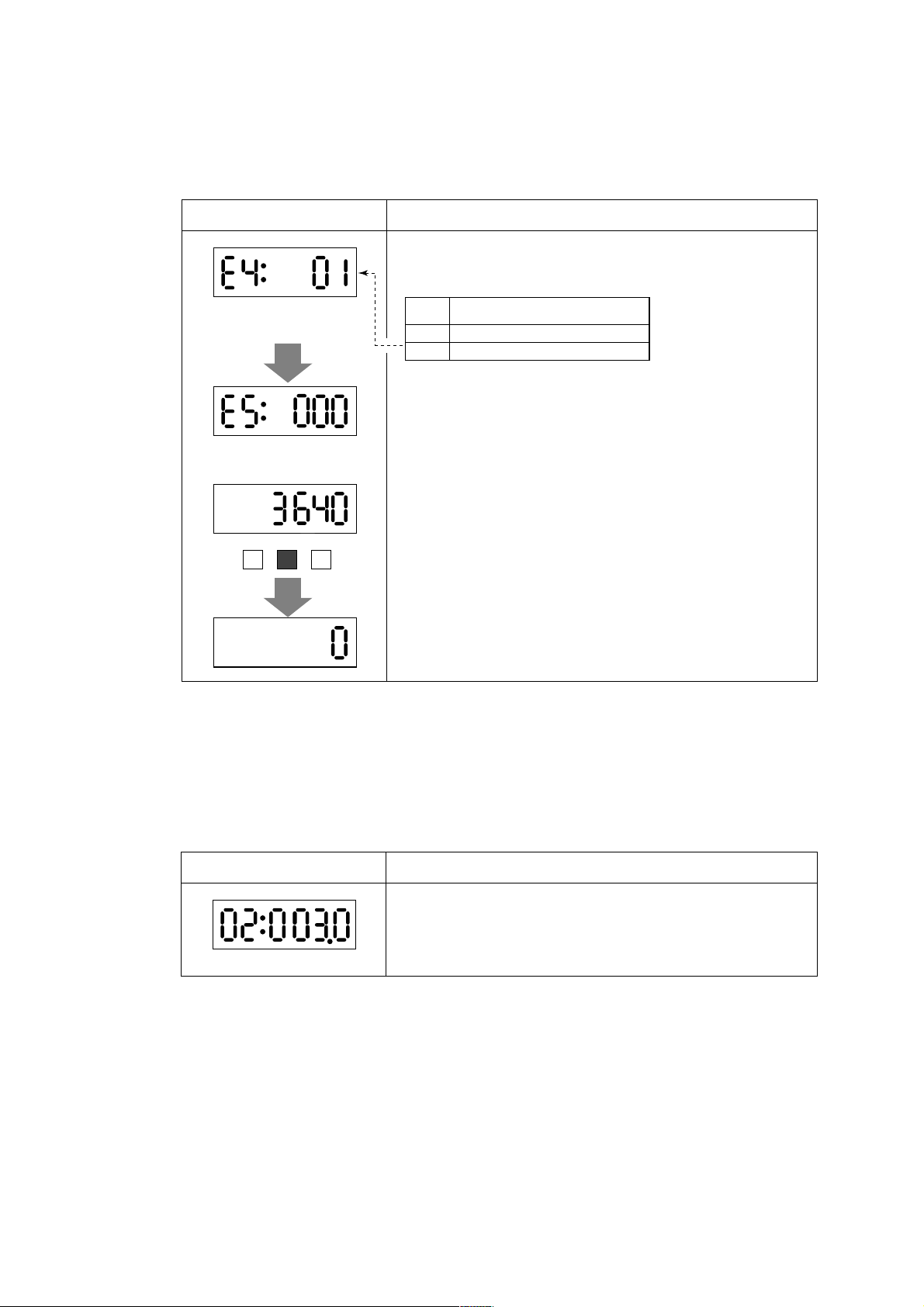
5.5.3 Resetting for Totalization Display
• This function is used to reset or preset totalization values of the display.
• Hold down the SHIFT key for more than 2 seconds while the totalization values of
the flow rate are displayed to set the totalization value to the value set in parameter
number "E5".
Display Description
Select totalization enable in parameter number "E4"
5. FUNCTION AND DATA SETTINGS
Default : 00 (inhibit)
Default : 0
SET SHIFT INC
5.5.4 Damping Time Constant
Code Description
0001Totalization presetting inhibit
Totalization presetting enabled
Set the totalization preset value in parameter number "E5". The initial value
is 0, if it is no setting, the function is zero setting.
Hold down the SHIFT key for more than 2 seconds while the totalization
values of the flow rate reading are displayed to set the totalization value to
the value set in parameter number "E5"
• The time constant can be changed by setting the parameter number "02" to suppress a
fluctuation or change a response time.
• The time constant influences to flow rate, pulse output and internal totalization.
However, in case "00" is selected in parameter number "N1", the pulse output and
internal totalization are not influenced by it.
Display Description
Set the value in parameter number "02".
Range of possible settings : 0.1 to 200.0 seconds.
Default : 3 seconds
5-10
IM 1E7C1-E
Page 32

5.5.5 Current Output During Alarm Occurrence
• The current output and display values during alarming can be selected in advance.
Display Description
Set a value for current output to be used during alarms in parameter number "11"
5. FUNCTION AND DATA SETTINGS
Default : 00
(2.4 mA or less)
5.5.6 Reversing Flow Direction
• The flow direction is set to "FORWARD" at the factory. This function enables to set
flow direction from "FORWARD" to "REVERSE"
Display Description
Default : 00
5.5.7 Limiting Current Output
Code Contents
00
2.4mA or less
01
4.0mA
02
Hold
03
21.6mA or more
Set the flow direction in parameter "14".
Code Contents
0001Forward direction
Reverse direction to flow arrow
(1) 4 to 20 mA low cut output (Current Output near by 0% Range)
• This function makes it possible to reduce fluctuations in the 0% region to reduce it to
0%.
Display Description
Output Set value
5.6mA(10%)
Default : 0(%)
4mA
Setting range : 0 to 10%
Input
0.5% 0.5%
Hysteresis : 1% fixed
5-11
IM 1E7C1-E
Page 33

(2) 4 to 20mA Low Limit
• This function limits the low end of the analog output.
• The default value is -20%, and a -10% (2.4mA) as reverse flow limit. Please set in
•2.4mA or less output in alarming is also limited.
5. FUNCTION AND DATA SETTINGS
case other setting is required.
Display Description
Output
Default : -20(%)
(3) High Limit on Current Output
• This function limits the high end of analog output.
• The default value is 120% (23.2mA). Please set in case other setting is required.
• 21.6mA or more output in alarming is also limited.
Display Description
Default : 120(%)
5.6mA(10%)
4mA
18.4mA(90%)
Setting Range
: -20 to 100%
Output
Setting range : 0 to 120%
5-12
IM 1E7C1-E
Page 34

5.5.8 Forward and Reverse Flow Measurement
• This function enables to measure forward and reverse flow rate without change the
flow tube direction.
•By setting reverse range, in case fluids flow to reverse direction the flow tube
measures it as reverse direction range automatically. In this time, a status signal that
shows changing into the reverse direction is output.
• To set the internal totalizing function for forward direction can also show it for
reverse direction by parameter settings.
• P+, P– terminals are used for output connection.
P+, P– terminals are for common use with pulse, alarm and other status output
NOTE
functions. Therefore, in case this function is used, other functions are not
available to use.
Display Description
F and R flow rate measurement can be selected as “02” in
parameter No. “10”.
5. FUNCTION AND DATA SETTINGS
(Default : 2%)
Code
00
Pulse output
01
Alarm output
02
Forward / reverse flow measurement
03
Automatic two range switching
04
Alarm output at low flow limit
05
Totalization switch
Reverse direction span can be set in parameter
No. “30”.
Flow rate unit is the same as forward direction span.
Futher reverse range span should be set in the same
number of places of decimals as forward range span.
Example: forward flow rate : 1.000 then revers flow rate
should be 4.000.
Hysteresis width at switching direction can be set in
parameter No. “31”.
It is the rate (%) of the smaller span, either forward or
reverse span.
Content
0%
Flow Rate
Hysteresis
Forward flow measurement: OFF
Reverse flow measurement: ON
When using reversed status (ON/OFF)
is required, it can be set in “n2 Output Mode”.
5-13
Status output
IM 1E7C1-E
Page 35

5.5.9 Automatic Two Range Switching
• When an input exceeds 100% of the first range, the range is automatically transferred
to the second range and the status output changes state.
• P+, P– terminals are used for output connection.
P+, P– terminals are for common use with pulse, alarm and other status output
NOTE
functions. Therefore, in case this function is used, other functions are not
available to use.
Display Description
5. FUNCTION AND DATA SETTINGS
Automatic two range transfer can be selected “03” in
parameter No. “10”.
Default : 00
Default : 10%
Code
Pulse output
00
Alarm output
01
Forward / reverse flow measurement
02
Automatic two range switching
03
Alarm output at low flow limit
04
Totalization switch
05
Forward second range can be set by calling up parameter
No. “33”.
Setting restrictions: First range ≤ 2nd range.
Further second range span should be set in the same
number of places of decimals as first range span in
parameter No. “03”.
Example: First range : 1.000 then second range should be
4.000
Hysteresis width at switching range can be set in
parameter No. “34”.
It is the rate (%) of first range span.
Output
100%
Content
2nd range1st range
0 %
1st range: OFF
2nd range: ON
When using reversed status (ON/OFF)
is required, it can be set in “n2 Output Mode”.
Status Output ON
Hysteresis (%)
Status Output
5-14
Flow Rate
IM 1E7C1-E
Page 36

5.5.10 Alarm Output at Low Flow Limit (Flow Switch)
• In case flow rate decrease under set level, an status signal is output.
P+, P– terminals are for common use with pulse, alarm and other status output
NOTE
functions. Therefore, in case this function is used, other functions are not
available to use.
Display Description
Alarm output at low flow limits can be selected “04” in
parameter No. “10”.
Default : 00
Code
00
Pulse output
01
Alarm output
02
Forward / reverse flow measurement
03
Automatic two range switching
04
Alarm output at low flow limit
05
Totalization switch
The Low Limit value can be set in parameter No. “36”
as parcentage for 4 to 20 mA.
5. FUNCTION AND DATA SETTINGS
Content
(Default : -10%)
(Default : 5%)
Hysteresis width is set in parameter No. “37”.
Output
low flow
limits
value.
Status
Output
On
When using reversed status (ON/OFF)
is required, it can be set in “n2 Output Mode”.
Hysteresis
5-15
IM 1E7C1-E
Page 37

5.5.11 Totalization Switch Output
• In case the Internal Totalization Value increase over set level, an alarm signal is
output.
P+, P– terminals are for common use with pulse, alarm and other status output
NOTE
functions. Therefore, in case this function is used, other functions are not
available to use.
Display Description
Default : 00
5. FUNCTION AND DATA SETTINGS
Totalization switch can be selected as “05” in parameter
No. “10”.
Code
00
Pulse output
01
Alarm output
02
Forward / reverse flow measurement
03
Automatic two range switching
04
Alarm output at low flow limit
05
Totalization switch
Switch level can be selected by calling up parameter No.
“06”.
Content
Default : 0
Totalization
999999
Setting value
10000
Status
Output
ON
When using reversed status (ON/OFF)
is required, it can be set in “n2 Output Mode”.
Input
5-16
IM 1E7C1-E
Page 38

5.5.12 Alarm Output
• This function is for status output from P+, P– terminals, when an alarm occurs.
P+, P– terminals are for common use with pulse, alarm and other status output
NOTE
functions.
Therefore, in case this function is used, other functions are not available to use.
•All of the alarms are able to output except empty pipe detection function that can be
• The status goes from close to open (OFF) during alarming.
Default : 00
Default : 00
selected in parameter No. “n7” as out of selection.
Display Description
The alarm output can be selected “01” in parameter No.
“10” and P+, P– terminals are only for alarm output.
Code
00
Pulse output
01
Alarm output
02
Forward / reverse flow measurement
03
Automatic two range switching
04
Alarm output at low flow limit
05
Totalization switch
The empty pipe output selection can be set in parameter
No. “n7”.
Code
00
ALARM
01
NO ALARM
Content
Content
5. FUNCTION AND DATA SETTINGS
* Item "n" can be opened by entering "55" in parameter number "L2".
5.5.13 Data Setting Enable / Inhibit
• This function can inhibit to change all data except parameter No. “ L1”.
However, auto zero adjustment function can work, if it has been set in parameter No.
“C1”.
And the preset totalization value function also can work, if it has been set in parameter
No. “E4”.
Display Description
Default : 01
The data setting inhibit item can be set "00" in parameter number "L1".
Code Content
0001INHIBIT
ENABLE
5-17
IM 1E7C1-E
Page 39

5.5.14 Procedure of Selecting Special Application Items
• Only the special application (“n” items) shipped being unpublished.
In case the “n” items should be used, it can be set “55” in parameter No. “L2”.
Display Description
It is possible to open up to item n when "55" is entered in parameter number
"L2".
Default : 00
Code Content
0001Accessible up to L parameters
Accessible up to n parameters
5.5.15 Rate Limit
• This function is used to remove noise that cannot be removed by increasing the
damping time constant.
• In case unexpected noise from step signal or slurry is entered, a basis is set to
recognize that signal is flow rate or noise.
The recoginition depends on rate limit value (upper and lower limit) and dead time
(sampling time).
• Determination of rate limit value and dead time.
5. FUNCTION AND DATA SETTINGS
Rate limit value:
Determine the level to reduce output
fluctuation.
For example, reducing 2% or more
fluctuation by setting as 2% to reduce.
Dead time T0:
Please determine the dead time
depending on output fluctuation width.
In case of noise of which is longer
than the dead time, please set the
dead time longer.
2%
2%
T
0
T
0
• Signal processing procedures:
The function sets a certain upper and lower limit (rate limit value) for first order
delay response values of flow rate data obtained in a previous sampling. If currently
sampled flow rate data exceeds or goes below the limit is regarded as current flow
rate value. Signals whose protruding portions show the same trends during a certain
number of sampling times (dead time)are identified as flow rate signals.
Example 1: Step Input
Input: 0 to 10%
Damping time constant: 3 sec.
Dead time: 3 sec.
Rate limit value: 1%
10%
Step Signal
Flow rate value
after rate limiting
(1)
1%
Dead time: 3 sec. (Sampling 80 ms × 18 times)
(2)
9
(3)
5-18
18
(4)
Flow rate value after
damping
63.2%
IM 1E7C1-E
Page 40
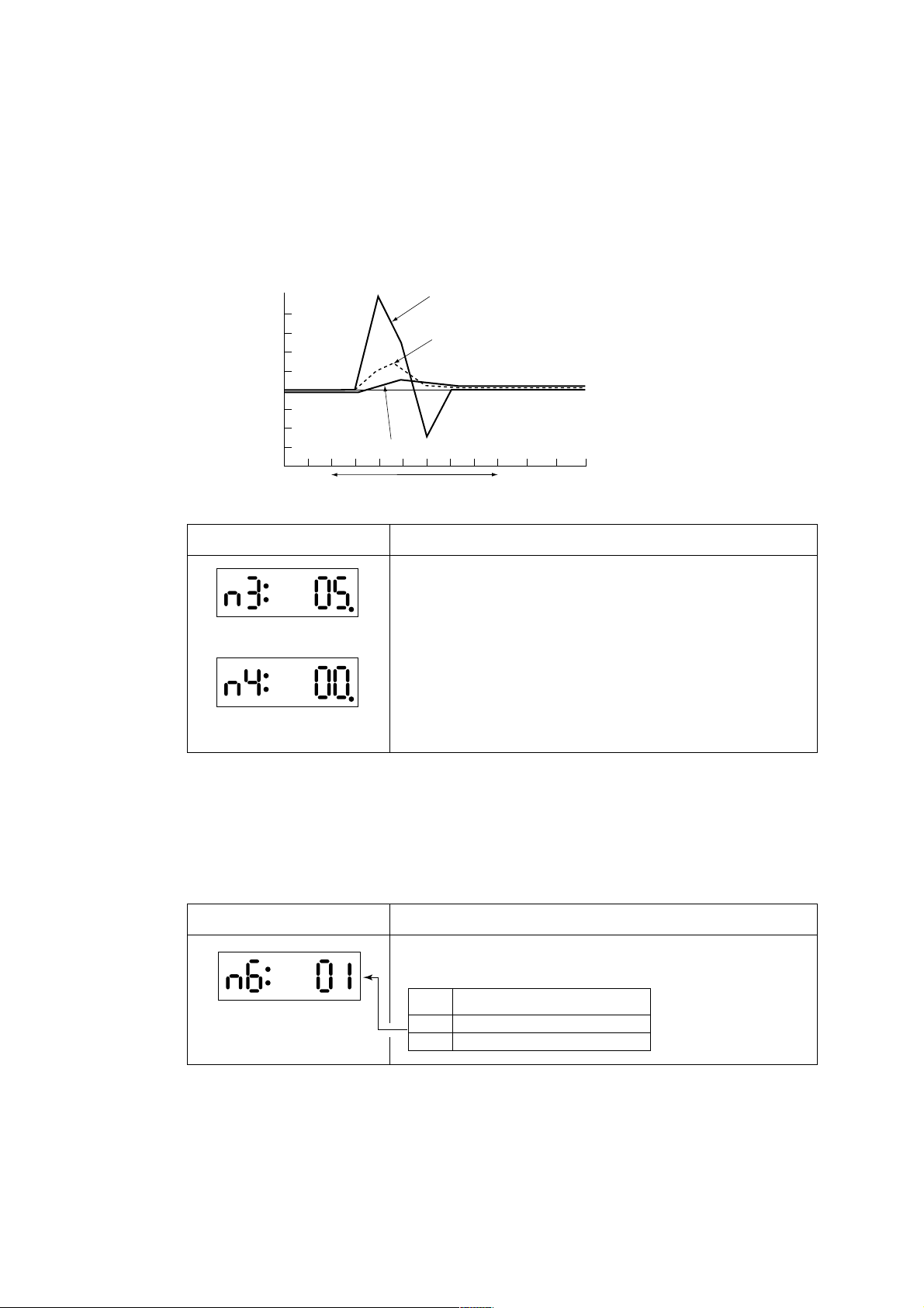
5. FUNCTION AND DATA SETTINGS
(1) Shows 1% response cause of excessive signal beyond the rate limit. However, actual
output is under damping that described by a solid line.
(2) Shows the flow rate signal (1%) of just after damping calculation (1) and rate limit
value.
(3) This signal is recognized as a flow rate signal since it does not return to within the
rate limit value within the dead time.
(4) The output signal follows the damping curve and tracks the step signal.
Example 2: Slurry Noise
Slurry Noise
Flow rate value after
rate limiting
+1%
–1%
Flow rate value after rate limiting and damping.
Dead time: 1 sec.
Display Description
Set a rate limit value in parameter number "n3".
Setting Range : 0 to 10%.
Default : 5%
Set the dead time in parameter number "n4".
Setting Range : 0 to 15 seconds.
Default : 0sec
Input: 0 to 10%
Damping time constant: 1 sec.
Dead time : 1 sec.
Rate limit value: 1%
The left figure shows that the slurry
noise is not a flow rate signal.
5.5.16 Pulsating Flow
•The pulsating flow produced by a plunger pump results in inaccurate average flow
Display Description
Default : 00
*Item "n" can be opened by entering "55" in parameter number "L2".
rate values. This function makes it possible to accurately track flow rate changes and
control calculation.
Select "01" (pulsating flow counteraction) in parameter number "n6".
Code Contents
0001Nomal
Counteracting pulsating flow
*Item "n" can be opened by entering "55" in parameter number "L2".
5-19
IM 1E7C1-E
Page 41

6. OPERATION VIA BRAIN TERMINAL
6. OPERATION VIA BRAIN TERMINAL
Products provided with / BR (BRAIN communication function) come equipped with a
BRAIN communication function which allows them to communicate with dedicated
BRAIN terminals (BT) or CENTUM systems. In the BRAIN series communications
system, a ±2 mA, 2.4 kHz modulated signal is superimposed onto the 4 to 20 mA DC
analog signal for data transmission. Since the modulated wave is an AC signal, superimposed on the analog signal will cause no error in the DC component of the analog
signal. Thus, monitoring can be performed via communications while the ADMAG AE
is online.
A BRAIN Terminal can be connected to the terminals shown in Figure 6.1 on products
that are not provided with a / BR (BRAIN communication function).
6.1 Operation Via the BT200
This section describes the operation procedures using a BRAIN terminal. For details on
the functions of the ADMAG AE, see Chapter 5, "Function and Data Settings." And
also, see the "BT200 Instruction Manual" (IM 1C0A11-01E) for more detailed information.
6.1.1 BT200 Connections
(1) Connecting BT200 to Converter
-CoCA-(Communication) is
displayed during communication.
Use these
terminals when
the instruction
does not have
a display.
Figure 6.1 Connection of BT200 to Flow Converter
For products not provided with the / BR (BRAIN communication function), the terminals for BRAIN communication are provided on the circuit board. Please connect BT200
to the terminals on the circuit board directly.
(2) Connecting the BT200 to a 4 to 20 mA DC Transfer Line
The communication signal of the ADMAG AE with the / BR function (optional specification) is superimposed onto the 4 to 20 mA DC analog signal to be transferred.
Intermediate
terminals
4 to 20 mA DC signal
transmission line
Control room
Terminal board
Receiving instrument
Receiver resistance,
250 Ω to 600 Ω
Figure 6.2 Communicating via a 4 to 20 mA DC Signal Line
6-1
IM 1E7C1-E
Page 42

6.1.2 BT200 Keypad Layout
Figure 6.3 shows the key pad lay out of the BT200.
MENU BATTERY
A:DISPLAY
B:SET
C:ADJUST
D:DISP SEL
E:TOTAL SET
F:PULSE SET
HOME SET AJD ESC
6. OPERATION VIA BRAIN TERMINAL
LCD
8 lines with 21 characters each
Function keys
Executes the commands displayed
at the bottom of the screen.
Arrow keys
• Selects an item.
• Moves the cursor.
Power
Inverse video bar
Menu panel
Major parameters items
A maximum of six items are displayed.
MENU BATTERY
A:DISPLAY
B:SET
C:ADJUST
D:DISP SEL
E:TOTAL SET
F:PULSE SET
HOME SET ADJ ESC
ENT key
• Goes to the selected item.
• Sets the entry data to the object
communication instrument.
Alphanumeric keys
• Enters a number.
• Enters letters when pressed
together with the shift key.
Shift keys
Parameter panel
Parameter data
A maximum of three items are displayed.
PARAM
A10:FLOW RATE(%)
0.6%
A20:FLOW RATE
0.06m3/h
A30:TOTAL
0
DATA DIAG PRINT ESC
Figure 6.3 Key Layout and Functions
6-2
Function commands
IM 1E7C1-E
Page 43

6.1.3 Major BT200 Key Functions
(1) Entry of Alphanumeric Characters
Numbers, codes and letters can be entered in combinations of the alphanumeric keys and
the SHIFT key.
• Entry of numbers, codes and a space (0 to 9, . , -, )
Entering of them is possible by using the alphanumeric keys.
Example of entry Key Operation
6. OPERATION VIA BRAIN TERMINAL
-4.3
1 -0.3
wx
–
MN
1
GH
4
YZ
SPACE
UV
•
wx
–
QR
3
ST0UV•QR
• Entry of letters
Press an alphanumeric key while one of the SHIFT keys is pressed and the letter on the
same side of the key as the shift key that is pressed can be entered. Press the SHIFT key
each time when entering a letter.
B
A
7
■
SHIFT
The letter on the
left side of the
alphanumeric key
is entered.
The letter on the
right side of the
alphanumeric key
is entered.
■
SHIFT
3
Example of entry Key operation
WIC
J.B
■
SHIFT
SHIFT
WX I J
–
IJ
■■
5
■
SHIFT
UV
•
SHIFT
• Selection of uppercase / lowercase of letters
Uppercase and lowercase letters can be selected alternately by pressing the function key
[F2] (CAPS).
Entry of uppercase letters
CODE CAPS CLR ESC
F1 F2 F3 F4
CODE caps CLR ESC
F1 F2 F3 F4
6-3
■
5
SHIFT
AB
7
Entry of lowercase letters
CD
8
IM 1E7C1-E
Page 44

6. OPERATION VIA BRAIN TERMINAL
• Entry of codes
Codes can be entered by pressing the function key [F1] (CODE). Every time [F1] CODE is
pressed, the codes are displayed at the cursor position in the order shown below.
/ . - , + * ) ( ' & % $ # " !
To enter characters after the codes above, move the cursor using the [>] key before entry.
Example of entry Key operation
(2) Function Keys
MENU
A:DISPLAY
B:SET
C:ADJUST
D:DISP SEL
E:TOTAL SET
F:PULSE SET
HOME SET ADJ ESC
F1 F2 F3 F4
Function keys
I/m
F2
(Lowercase
letter)
KL
■■
SHIFT
( I ) ( / ) ( m )
6
F1
SHIFT
MN
1
The functions of the function keys vary with the commands being displayed on the display
panel.
Command
ADJ
CAPS/caps
C LR
CODE
COPY*
DATA
DEL
DIAG
ESC
FEED*
Calls up the zero-adjustment menu.
Changes the uppercase / lowercase mode.
Clears entered data /deletes all data.
See the above “Entry of codes”
Prints parameters on the screen.
Updates parameter data.
Deletes one character.
Calls up the self-check screen.
Returns to the preceding screen.
Paper feed.
Description
HOME
LIST*
NO
OK
PARM
PON/POFF*
PRNT*
SET
SLOT
GO*
STOP*
UTIL
*The command is available only for BT200-P00.
Calls up the home menu (A : DISPLAY).
Prints all parameters of the menus.
Setting stop / re-setting. Returns to the previous
screen
Goes to the next screen.
Parameter number setting mode.
Printer output of data whose setting was changed
Mode on / off
Changes to the prints mode.
Calls up the setting menu. (B : SETTING)
Returns to the slot selection screen.
Starts print out.
Stops printing.
Transfers to the utility screen.
6-4
IM 1E7C1-E
Page 45

6.1.4 Displaying Flow Rate Data
Flow rate data can be displayed on the BT200 screen according to the following
procedure.
6. OPERATION VIA BRAIN TERMINAL
BRAIN TERMINAL
- -WELCOME- ID:BT200
Check cable connection
and press the ENT key.
UTIL FEED
ON/OFF
PARAMETER
01:MODEL
AE14-
02:TAG NO.
03:SELF CHECK
GOOD
OK
ENTER
MENU
A:DISPLAY
B:SET
C:ADJUST
D:DISP SEL
E:TOTAL SET
F:PULSE SET
HOME SET ADJ ESC
Turn the power on and the screen on the left appears after "please
wait..." is displayed for a few seconds.
Pressing the ENTER key causes the initial data screen on the left
to be displayed.
The tag number specified upon ordering is entered.
Inverse video bar
Pressing the F4 key or the ENTER key causes the menu screen on
the left to be displayed.
3
3
ENTER
/h
ENTER
/h
F4
or
PARAM
A10:FLOW RATE(%)
0.6%
A20:FLOW RATE
0.06m
A30:TOTAL
0
DATA DIAG ESCPRNT
PARAM
A10:FLOW RATE(%)
0.6%
A20:FLOW RATE
0.06m
A30:TOTAL
0
DATA DIAG PRNT ESC
F1
F2 F3
● With "A : DISPLAY" displayed on the menu panel in the
inverse video bar, press the ENTER key and the flow data
screen appears.
● A maximum of three data items can be displayed on one
screen.
● Data are communicated at an interval of 5 seconds. Thus, the
data are updated every 5 seconds.
● The arrow keys, [ ], [ ] or [ ], [ ], are used for page feeds or
item selection.
Execution of the function keys
F1: Updates the current data. Pressing this key causes forcible
communication with the connected instruments and the data
of the instruments are loaded to be read.
F2: Displays the self-check screen.
F3: Displays the parameter print screen.
F4: Returns to the previous panel (menu panel).
F4
<>
<
>
6-5
IM 1E7C1-E
Page 46
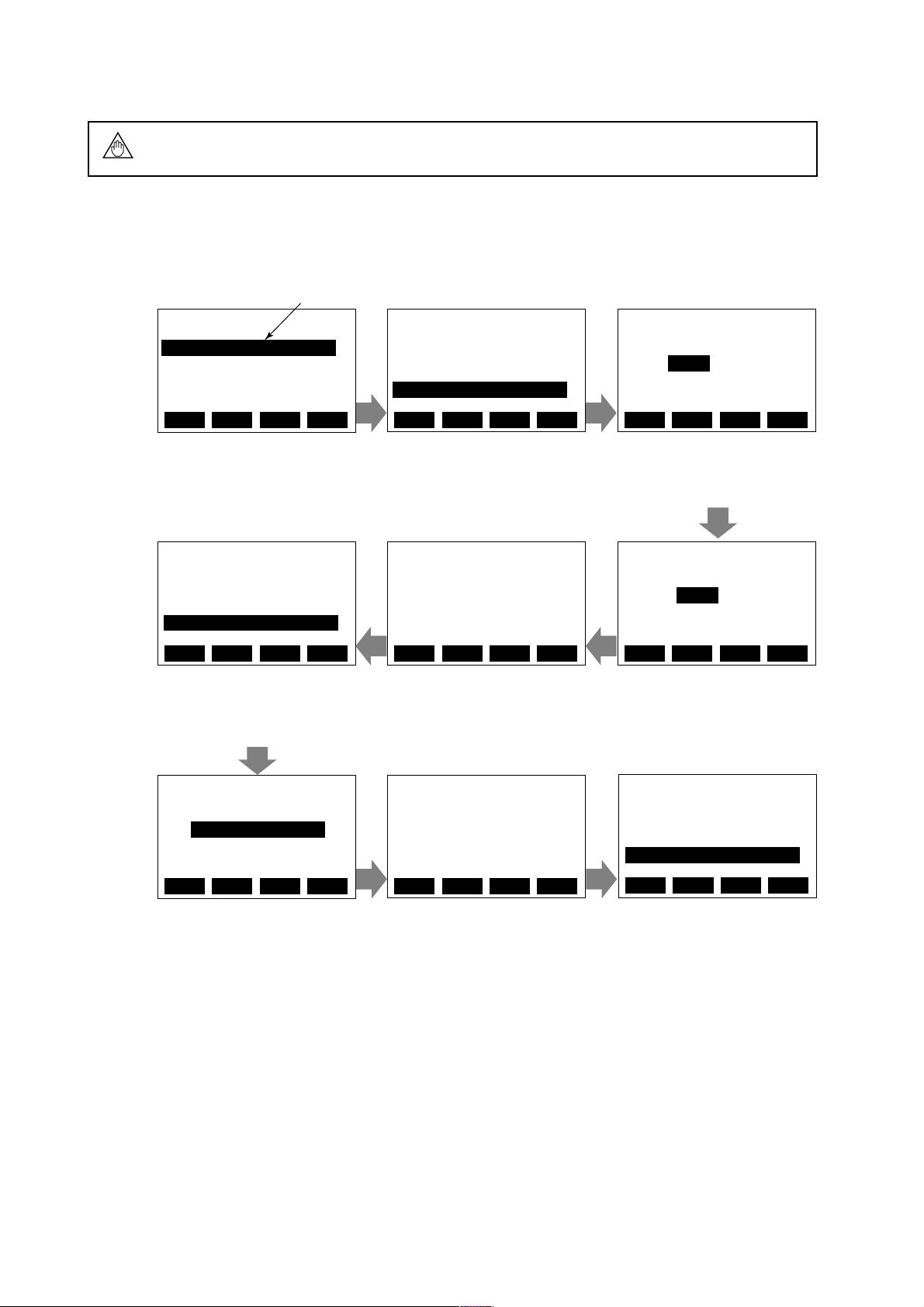
6.2 Setting Parameters
The three parameters must be set to obtain a connect signal. Nominal size, flow span
NOTE
6.2.1 Setting Nominal Size
MENU
A:DISPLAY
B:SET
C:ADJUST
D:DISP SEL
E:TOTAL SET
F:PULSE SET
HOME ADJ ESCSET
Call up the menu screen and move
the inverse video bar to “B : SET.”
and meter factor must be set.
Example: flow tube size 50mm
Inverse video bar
PARAM
B04:FLOW UNIT
m
B05:TIME UNIT
/s
B06:SIZE UNIT
mm
Press the ENTER key to call the
screen displaying the parameter sub
items. Move the inverse video bar
to “B06 : SIZE UNIT”.
6. OPERATION VIA BRAIN TERMINAL
SET
B06:SIZE UNIT
mm
< mm >
< inch >
ESCDIAGDATA
Pressing the ENTER key causes the
data setup screen to be displayed. If
the security screen is displayed, enter
the security code.*
CLR ESCDEL
SET
B05:TIME UNIT
/s
B06:SIZE UNIT
mm
B07:NOMINAL SIZE
100.0
ESCDIAGDATA
The screen displaying the parameter
sub-items is displayed again. Feed
the page using the arrow key and
move the inverse video bar to the
item “B07 : NOMINAL SIZE”
SET
B07:NOMINAL SIZE
100.0 mm
< 50.0 >
ESC
Enter “50.0” using the alphanumeric
keys.
SET
B06:SIZE UNIT
mm
OKNO
Pressing the ENTER key causes the
data display to blink. After
confirming it, press the ENTER key
once more and the above screen
appears. If the data are correct,
press the F4 key.
SET
B07:NOMINAL SIZE
50.0 mm
OKNO
Press the ENTER key twice and the
above screen appears. Check that the
data are correct, and press the F4
key.
SET
B06:SIZE UNIT
mm
< mm >
< inch >
CLR ESCDEL
Select “mm” .
PARAM
B05:TIME UNIT
/s
B06:SIZE UNIT
mm
B07:NOMINAL SIZE
50.0 mm
ESCSET CLRHOME
Setting is completed. The screen
returns to the preceding screen when
the F4 (ESC) key is pressed.
6-6
IM 1E7C1-E
Page 47

6.2.2 Setting Flow Span Via the BT200
Example: Flow span 10.00 m3/h
Inverse video bar
MENU
A:DISPLAY
B:SET
C:ADJUST
D:DISP SEL
E:TOTAL SET
F:PULSE SET
HOME ADJ ESCSET
Call up the menu screen and move
the inverse video bar to “B : SET.”
PARAM
B01:TAG NO
B02:DAMPING
3.0 S
B03:FLOW SPAN
1.00 m/s
Press the ENTER key to call the
screen displaying the parameter sub
items. Move the inverse video bar
to “B03 : FLOW SPAN”.
6. OPERATION VIA BRAIN TERMINAL
SET
B03:FLOW SPAN
1.00 m/s
0
ESCDIAGDATA
CLR ESCDEL
Pressing the ENTER key causes the
data setup screen to be displayed. If
the security screen is displayed, enter
the security code.*
SET
B02:DAMPING
3.0 S
B03:FLOW SPAN
10.0 m/s
B04:FLOW UNIT
m
ESCDIAGDATA
The screen displaying the parameter
sub-items is displayed again. Feed
the page using the arrow key and
move the inverse video bar to the
item “B04 : FLOW UNIT.”
SET
B04:FLOW UNIT
m
< km
< m
< l >
< cm
3
>
3
>
3
>
ESC
Pressing the ENTER key causes the
data setup screen to be displayed.
Move the inverse video bar to “m
3
.”
If the security screen appears, enter
the security code* to display the
above screen.
* km
3
: 103m
3
cm3 : (10-2m)
3
PARAM
B03:FLOW SPAN
10.0 m
B04:FLOW UNIT
m
3
3
/h
B05:TIME UNIT
/h
ESCSET CLRHOME
Setting is completed. The screen
returns to the preceding screen when
the F4 (ESC) key is pressed.
SET
B03:FLOW SPAN
10.0 m/s
SET
B03:FLOW SPAN
1.00 m/s
10.0
OKNO
Pressing the ENTER key causes the
data display to blink. After
confirming it, press the ENTER key
once more and the above screen
appears. If the data are correct,
Enter “10.0” using the alphanumeric
keys. (Enter 10.0 only for the sub
item “B03 : FLOW SPAN”.) The
3
/h is selected at items B04
unit, m
and B05.
press the F4 key.
SET
B04:FLOW UNIT
m
3
SET
B03:FLOW SPAN
10.0 m/s
B04:FLOW UNIT
m
B05:TIME UNIT
/s
OKNO
Press the ENTER key twice in
succession and the above screen
appears. Check that the data are
correct, and press the F4 key.
The screen displaying the parameter
sub-items appears again. Feed the
page using the arrow key and move
the inverse video bar to “B05 :
TIME UNIT”.
SET
B04:TIME UNIT
/h
SET
B05:TIME UNIT
/s
< /s >
< /d >
< /h >
< /m >
OKNO
Press the ENTER key twice in
succession and the above screen
appears. Check that the data are
correct, and press the F4 key.
Pressing the ENTER key causes
the data setup screen to be
displayed. Move the inverse video
bar to “/h”.
*For entry of the security code, see IM 1C0A11-01E.
CLR ESCDEL
3
ESCDIAGDATA
ESC
6-7
IM 1E7C1-E
Page 48
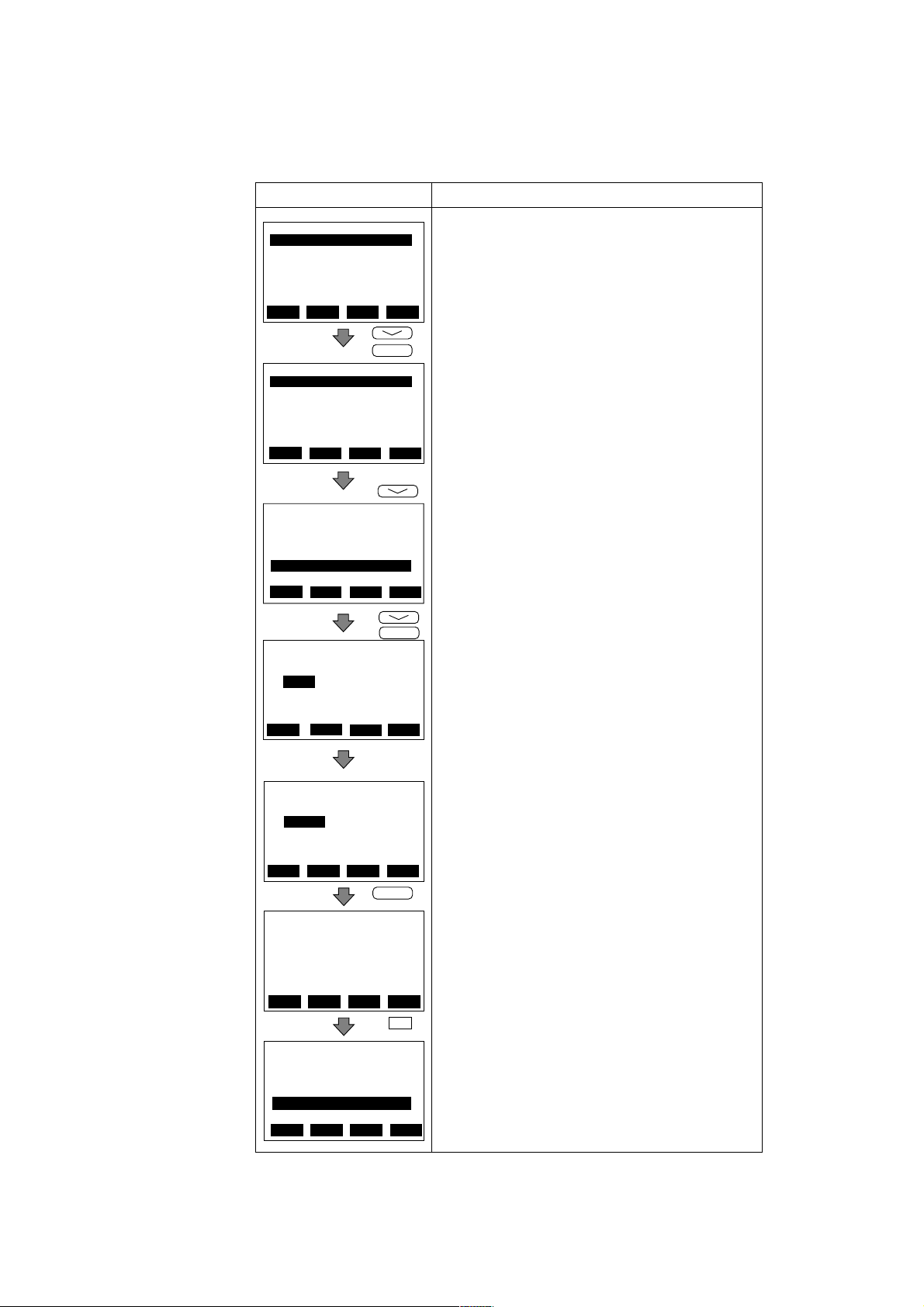
6.2.3 Setting Meter Factor
The meter factors are engraved on the data plate of the combined flow tube.
Example: set " 1.1200" as meter factor(L).
6. OPERATION VIA BRAIN TERMINAL
Display Description
MENU
A:DISPLAY
B:SET
C:ADJUST
D:DISP SEL
E:TOTAL SET
F:PULSE SET
SET
HOME
PARAM
B01:TAG NO
B02:DAMPING
3.0 s
B03:FLOW SPAN
1.00 m/s
DATA
DIAG
PARAM
B06:SIZE UNIT
mm
B07:NOMINAL SIZE
50.0mm
B08:LOW MF
1.0000
DATA
DIAG
SET
B08:LOW MF
1.0000
0
ADJ
ESC
ENTER
ESC
ESC
ENTER
Call up the menu screen
Use the arrow key to select “B:SET” with the arrow key and press
the ENTER key.
Then, the parameter panel is displayed.
Select “B08:LOW MF” by feeding the page with the arrow key and
press ENTER key to call up the following data setup panel.
Press ENTER key on the parameter panel to display the data setup
panel as shown on the left.
(If the security panel appears, enter the security code.*)
CLR
DEL
SET
B08: LOW MF
1.0000
1.1200
DEL
SET
B08: LOW MF
1.1200
PARAM
B06: SIZE UNIT
inch
B07: NOMINAL SIZE
2.00 inch
B08: LOW MF
1.1200
DATA DIAG ESC
“1.1200”
CLR
ENTER
NO OK
ESC
ESC
F4
Set “1.1200” using the alphanumeric keys. Default:1.0000
Press ENTER key twice at an interval of a few seconds.
×2
The display as shown on the left appears.
If the data is correct, press F4 key [OK].
The parameter panel is displayed again.
The setting is completed.
Set meter factor(H) to parameter No B09.
Set in the same way.
* For entry of the security code, see IM1C0A11-01E.
6-8
IM 1E7C1-E
Page 49

6.2.4 Power Frequency
6. OPERATION VIA BRAIN TERMINAL
IMPORTANT
In case of DC power supply version, setting power frequency is required.
Display Description
PARAM
B10:OUTPUT FUNC
PULSE OUT
B11:4-20ALM OUT
2.4mA OR LESS
B12:POWER FREQ
50.03Hz
DATA ESCDIAG
6.2.5 Pulse Output (Refer to 5.5.1)
Example setting : 10 L output per pulse in a flow rate span of m3/h
PARAM
B10:OUTPUT FUNC
B11:4-20ALM OUT
2.4mA OR LESS
B12:POWER FREQ
50.03Hz
DATA ESCDIAG
PARAM
F01:PULSE UNIT
m UNIT/P
F02:PULSE SCALE
10 m UNIT/P
F03:PULSE LOWCUT
3. %
DATA ESCDIAG
PALAM
F02:PULSE UNIT
10 m UNIT/P
F03:PULSE LOWCUT
3. %
F04:PULSE WIDTH
50% DUTY
DATA ESCDIAG
* The "N" item can be opened by
entering "55" in parameter number
"L02".
Normally, these are all required settings.
The following settings are made depending on the application that is used.
PARAM
N01:TOTAL/PULSE
DAMP
N02:OUTPUT MODE
ON
N03:RATE LIMIT
5. %
DATA ESCDIAG
Set value in areas where the frequency differs in "B12 : POWER FREQ".
Default:50.00Hz.
Setting Range : 47.00 to 53.00Hz
Display Description
The pulse output terminals (P+, P-) are also used for alarms. Select "Pulse
output" in parameter number "B10".
PULSE OUT
ESC
Code
PULSE OUT
ALARM OUT
BI DIRECTION
AUTO 2 RANGES
LOW ALARM
TOTAL SWTICH
Select the volume unit for the pulse weight in parameter number "B04".
Code Volume unit
n UNIT/P
m UNIT/P
m UNIT/P
UNIT/P
k UNIT/P
M UNIT/P
P ULSE/s
Example) When pulses are to be output per same liter with the flow rate span
of m3/h, select "m UNIT/P" since a L(liter) = 10
Set the pulse weight "10 ( L )" in parameter number "F02".
*Since parameter number "F02" is a 5-digit data item, scrolling is
necessary to display all the data. Mind the decimal point when seting are
made. (The decimal point can be moved if required.)
Set the low cut range percentage in parameter "F03".
Range of setting : (0 to 100% of span)
Select the pulse width in parameter number "F04"
Code Pulse width
50%DUTY
0.5ms
1ms
20ms
33ms
50ms
100ms
Select instantaneous flow rate or flow rate after damping data for the
pulse output.
(The damping time value is the value set in "B02")
Set parameter "N02" to "OFF" when the pulse output transistor is to be
off active.
Pulse output
Alarm output
Forward / reverse flow measurement
Automatic two range switching
Alarm output at low flow limits
Totalization switch
Volume unit in that for the flow rate span × 10
Volume unit in that for the flow rate span × 10
Volume unit in that for the flow rate span × 10
Volume unit in that for the flow rate span × 1
Volume unit in that for the flow rate span × 10
Volume unit in that for the flow rate span × 10
Number of pulses output per second at 100% of
output
(Max. of 1000P/s Min. 0.0001P/s)
(Max. of 1000P/s Min. 0.0001P/s)
(Max. of 500P/s Min. 0.0001P/s)
(Max. of 25P/s Min. 0.0001P/s)
(Max. of 15P/s Min. 0.0001P/s)
(Max. of 10P/s Min. 0.0001P/s)
(Max. of 5P/s Min. 0.0001P/s)
Content
Default : DAMP
-9
-6
-3
3
6
-3
3
m
6-9
IM 1E7C1-E
Page 50

6. OPERATION VIA BRAIN TERMINAL
6.2.6 Display of Internal Totalization Values (Refer to 5.5.2)
Example : 10 L output per pulse in a flow rate span of m3/h
Display Description
Select the volume unit for the pulse weight in parameter number "E01."
Code Volume unit
PARAM
E01:TOTAL UNIT
m UNIT/P
E02:TOTAL SCALE
10 m UNIT/P
E03:TOTAL LOWCUT
3. %
DATA ESCDIAG
n UNIT/P
UNIT/P
m UNIT/P
UNIT/P
k UNIT/P
M UNIT/P
PULSE/s
Example) When pulses are to be output per same liter with the flow rate
span of m
Volume unit used in that for the flow rate span × 10
Volume unit used in that for the flow rate span × 10
Volume unit used in that for the flow rate span × 10
Volume unit used in that for the flow rate span × 1
Volume unit used in that for the flow rate span × 10
Volume unit used in that for the flow rate span × 10
Number of pulse output per second at 100% of output
3
/h, select "m UNIT/P" since a L(liter) =10-3m
Set the pulse weight "10(L)" in parameter number "E02."
Set the low cut range percentage in parameter "E03."
PARAM
N01:TOTAL/PULSE
DAMP
N02:OUTPUT MODE
ON
N03:RATE LIMIT
Range of setting : (0 to 100% of span)
Select instantaneous flow rate or flow rate after damping for the pulse
output.
(The damping time value is the value set in "B02."
Default : DAMP (damped flow rate data)
5. %
DATA ESCDIAG
* The "N" item can be opend by entering "55" in parameter number "L02".
6.2.7 Resetting for Totalization Display (Refer to 5.5.3)
-9
-6
-3
3
6
3
Display Description
PARAM
E04:TOTAL SET
ENABLE
E05:TL SET VALUE
0
E10:TOTAL SWITCH
0
DATA ESCDIAG
PARAM
A10:FLOW RATE(%)
50 .0 %
A20:FLOW RATE
50 .0 m
A30:TOTAL
12345
DATA PRNT ESCDIAG
SETTING
A30:TOTAL
0
CLR ESC
3
/h
ENTER
Select totalization enable in parameter number “E04.”
Code Description
ENABLE
INHIBIT
Totalization presetting enabled
Totalization presetting inhibit
Set the totalization preset value in parameter number “E05.”
The default is 0 and if the setting is omitted, the parameter functions
reset to 0.
If the ENT key is pressed twice while “A30 : TOTAL” is displayed on
the setting screen, the totalization value (A30 : TOTAL) will be
replaced with the values set in “E05.”
6-10
IM 1E7C1-E
Page 51

6.2.8 Damping Time Constant (Refer to 5.5.4)
Display Description
6. OPERATION VIA BRAIN TERMINAL
PARAM
B01:TAG NO
B02:DAMPING
3.0 s
B03:FLOW SPAN
1.00 m/s
DATA ESCDIAG
Set the value in parameter number "B02."
Setting Range : 0.1 to 200.0 seconds.
6.2.9 Current Output during Alarm Occurrence (Refer to 5.5.5)
Display Description
PARAM
B10:OUTPUT FUNC
PULSE OUT
B11:4-20 ALM OUT
2.4mA OR LESS
B12:POWER FREQ
50.03Hz
DATA ESCDIAG
Set the value for current output to be used during alarms in parameter
"B11."
(Default : 2.4 mA or less)
Code
2.4mA OR LESS
4.0mA
HOLD
21.6mA OR MORE
2.4 mA or less
4.0 mA
Fixed to output when alarm is
generated.
21.6 mA or more
Content
6.2.10 Reversing Flow Direction(Refer to 5.5.6)
Display Description
PARAM
B13:VELOCITY CHK
5 m/s
B14:FLOW DIR
REVERSE
B60:SELF CHECK
GOOD m/s
DATA ESCDIAG
The flow direction can be set in parameter number "B14"
Code
FORWARD
REVERSE
Forward direction
Reverse direction to flow arrow
6.2.11 Limiting Current Output (Refer to 5.5.7)
(1) 4 to 20 mA low cut output (Current Output near by 0% Range)
Display Description
PARAM
G01:4-20 LOW CUT
10 %
G02:4-20 LOW LMT
-20 %
G03:4-20 H LMT
120 %
DATA
DIAG
5.6mA(10%)
ESC
Output Set value
4mA
Description
0.5% 0.5%
Setting range : 0 to 10%
6-11
Default:0%
Hysteresis:1% fixed
IM 1E7C1-E
Page 52

(2) 4 to 20 mA Low Limit
6. OPERATION VIA BRAIN TERMINAL
Display Description
PARAM
G01:4-20 LOW CUT
0 %
G02:4-20 LOW LMT
10 %
G03:4-20 H LMT
110 %
DATA ESCDIAG
Setting Range : -20 to 100%
Default : -20%
5.6mA(10%)
(3) 4 to 20 mA High Limit
Display Description
PARAM
G01:4-20 LOW CUT
0 %
G02:4-20 LOW LMT
-20 %
G03:4-20 H LMT
90 %
DATA ESCDIAG
18.4mA(90%)
Setting range : 0 to 120%
Default : 120%
Output
6.2.12 Forward and Reverse Flow Measurement (Refer to 5.5.8)
Display Description
Output
4mA
PARAM
B09:HIGH MF
1.0000
B10:OUTPUT FUNC
BI DIRECTION
B11:4-20 ALM OUT
2.4mA OR LESS
DATA ESCDIAG
PARAM
B30 :REV. SPAN
B31 :BI. DIREC HYS
B33 :FOR. SPAN2
DATA ESCDIAG
Select "BI DIRECTION" (Direct / reverse flow measuring mode) in
parameter number "B10".
Code
PULSE OUT
ALARM OUT
BI DIRECTION
AUTO 2 RANGES
LOW ALARM
TOTAL SWTICH
Reverse direction span can be set in parameter No."B30".
Flow rate unit is the same as forward direction span.
Further reverse range span should be set in the same number of places of
decimals as forward range span.
Example: forward flow rate : 1.000 then reverse flow rate should be 4.000.
Hysteresis width at switching direction can be set in parameter No."B31".
It is the rate(%) of the smaller span, either forward or reverse span.
Pulse output
Alarm output
Forward / reverse flow measurement
Automatic two range switching
Alarm output at low flow limits
Totalization switch
Content
6-12
IM 1E7C1-E
Page 53
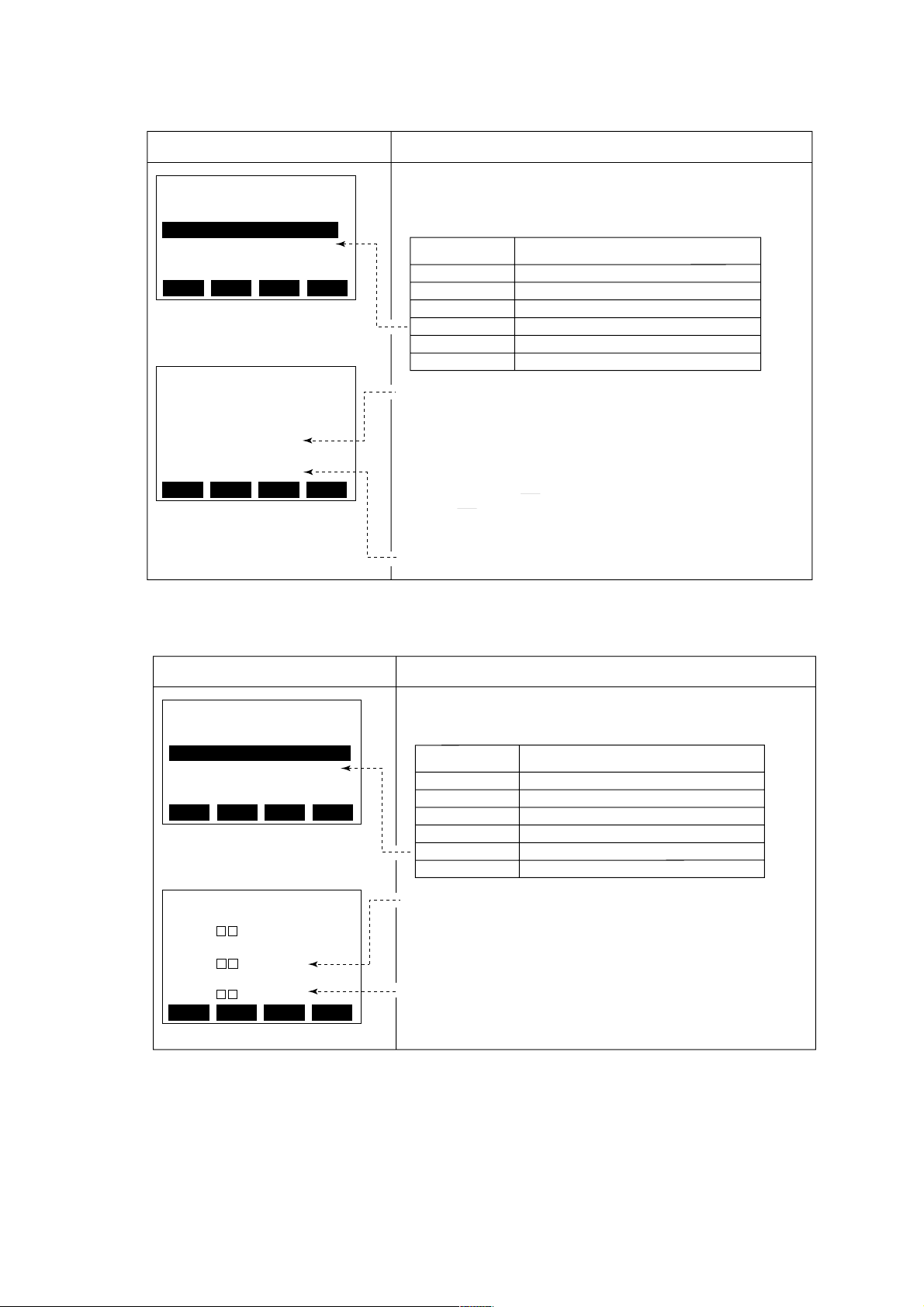
6.2.13 Automatic Two Range Switching (Refer to 5.5.9)
6. OPERATION VIA BRAIN TERMINAL
Display
PARAM
B09:HIGH MF
1.0000
B10:OUTPUT FUNC
AUTO 2 RANGES
B11:4-20 ALM OUT
2.4mA OR LESS
DATA ESCDIAG
PARAM
B31 :BI DIREC HYS
B33 :FOR. SPAN2
B34 :AUTO RNG HYS
DATA ESCDIAG
Description
Select "AUTO 2 RANGES" (Automatic two range transfer) in parameter
number "B10".
Code
PULSE OUT
ALARM OUT
BI DIRECTION
AUTO 2 RANGES
LOW ALARM
TOT AL SWTICH
Forward second range can be set by calling up parameter No. “B33”.
Setting restrictions: First range ≤ 2nd range.
Further second range span should be set in the same number of places of decimals
as first range span in parameter No. “B03”.
Example: First range : 1.000 then second range should be
4.000
Hysteresis width at switching range can be set in parameter No. “B34”.
It is the rate (%) of first range span.
Pulse output
Alarm output
Forward / reverse flow measurement
Automatic two range switching
Alarm output at low flow limits
Totalization switch
Content
6.2.14 Alarm Output at Low Flow Limits (Flow Switch) (Refer to 5.5.10)
Display Description
PARAM
B09:HIGH MF
1.0000
B10:OUTPUT FUNC
LOW ALARM
B11:4-20 ALM OUT
2.4mA OR LESS
DATA ESCDIAG
PARAM
B34 :AUTO RNG HYS
B36 :LOW ALARM
B37 :L. ALARM HYS
DATA ESCDIAG
Select "LOW ALARM" (Alarm output at low flow limits) in parameter
number "B10" .
Code
PULSE OUT
ALARM OUT
BI DIRECTION
AUTO 2 RANGES
LOW ALARM
TOT AL SWTICH
Set the comparison level in parameter number "B36" .
Set the hysteresis in parameter "B37" .
Pulse output
Alarm output
Direct / reverse flow measurement
Automatic two range transfer
Alarm output at low flow limits
Totalization switch
Content
6-13
IM 1E7C1-E
Page 54

6.2.15 Totalization Switch Output (Refer to 5.5.11)
Display Description
6. OPERATION VIA BRAIN TERMINAL
PARAM
B09:HIGH MF
1.0000
B10:OUTPUT FUNC
TOTAL SWITCH
B11:4-20 ALM OUT
2.4mA OR LESS
DATA ESCDIAG
PARAM
E05 :TL SET VALUE
E06 :TOTAL SWITCH
E10 :TL USER UNIT
DATA ESCDIAG
Select "TOTAL SWITCH" (Totalization Switch) in parameter number "B10"
Code
PULSE OUT
ALARM OUT
BI DIRECTION
AUTO 2 RANGES
LOW ALARM
TOT AL SWTICH
Set the switch level in parameter number "E6".
Pulse output
Alarm output
Forward / reverse flow measurement
Automatic two range switching
Alarm output at low flow limits
Totalization switch
Content
6.2.16 Alarm Output (Refer to 5.5.12)
Display Description
PARAM
B10:OUTPUT FUNC
ALARM OUT
B11:4-20 ALM OUT
2.4mA OR LESS
B12:POWER FREQ
50.03Hz
DATA ESCDIAGDATA ESCDIAG
PARAM
N06 :PULSING FLOW
NO
N07 :EMPTY PIPEB
ALARM
N60 :SELF CHECK
GOOD
DATA ESCDIAG
* The "N" item can be opend by entering "55" in parameter number "L02".
Set "ALARM" in parameter number "B10" to use the P+ and P- terminals
for alarm output only.
Select whether an empty pipe alarm is to be performed or not in
parameter number "N07."
Code
PULSE OUT
ALARM OUT
BI DIRECTION
AUTO 2 RANGES
LOW ALARM
TOTAL SWTICH
Code
ALARM
NO ALARM
ALARM
NO ALARM
Content
Pulse output
Alarm output
Forward / reverse flow measurement
Automatic two range switching
Alarm output at low flow limits
Totalization switch
Content
6-14
IM 1E7C1-E
Page 55

6.2.17 Data Setting Enable / Inhibit (Refer to 5.5.13)
• This function makes it possible to inhibit all data changes (except L1). However,
automatic zero adjustment can be made if the automatic zero-adjustment function is
enabled (set in C1). Also, totalization presetting can be done if the totalization
presetting function is enabled (set in E4).
Display Description
6. OPERATION VIA BRAIN TERMINAL
PARAM
L01:TUNING
INHIBIT
L02:KEY
00
L60:SELF CHECK
GOOD
DATA ESCDIAGDATA ESCDIAG
Selecting "INHIBIT" in parameter number "L01" disables data setting.
Code
ENABLE
INHIBIT
Data setting enabled.
Data setting inhibit.
Content
Default
6.2.18 Procedure of Selecting Special Application Items (Refer to 5.5.14)
Display Description
PARAM
L01:TUNING
INHIBIT
L02:KEY
55
L60:SELF CHECK
GOOD
DATA ESCDIAGDATA ESCDIAG
It is possible to open up to item N when "55" is entered in parameter
number "L02."
Code
00
55
Accessible up to L parameters
Accessible up to n parameters
Content
Default
6.2.19 Rate Limit (Refer to 5.5.15)
Display Description
PARAM
N03:RATE LIMIT
5 %
N04:DEAD TIME
0 s
N05:POWER SYNCH
YES
DATA ESCDIAGDATA ESCDIAG
Set the rate limit value in parameter number "N03." Range of possible
settings : 0 to 10%.
Set the dead time in parameter number "N04."
Range of possible settings : 0 to 15 seconds.
Default : 0
(Rate limit function off)
6.2.20 Pulsating Flow (Refer to 5.5.16)
Display Description
PARAM
N04:DEAD TIME
0
N05:POWER SYNCH
YES
N06:PULSING FLOW
YES
DATA ESCDIAG
Select "YES" (pulsating flow counteraction) in parameter number
"N06" . (Default : NO)
Code
NO
YES
Content
Normal
Counteracting pulsating flow
6-15
IM 1E7C1-E
Page 56

6.2.21 User-Defined Units Via the BT200
This function displays the instantaneous flow rate indicated in "A20 FLOW RATE" in
units other than those selectable with B04. If the specific gravity of the fluid is known,
the instantaneous flow rate can be displayed in weight units.
(1) User-Defined Units for Instantaneous Flow Rate
Example : Displaying the flow rate of a fluid (its specific gravity is 2) in weight (kg)
in a flow rate span of 10m3/h. When the flow rate is 100%, 20,000kg is
displayed.
6. OPERATION VIA BRAIN TERMINAL
Display
PARAM
D02:FL USER SEL
PROVIDED
D03:FL USER SPAN
20000.0
D10:FL USER UNIT
kg/h
DATA ESCDIAGDATA ESCDIAG
PARAM
A10:FLOW RATE(%)
100.0%
A20:FLOW RATE
20000.0 kg/h
A30:TOTAL
12345
DATA ESCDIAGDATA ESCDIAG
Select "PROVIDED" in "D02."
For item "D03," set the value to be displayed in "A20 FLOW RATE"
when the flow rate is 100% in the span set in "B03FLOW SPAN." Set
the unit in "D10".
Set the user-defined unit in "D10."
The instantaneous flow rate in user-defined unit can be displayed in
"A20 : FLOWRATE."
(2) User-Defined Units for Totalization Values
User-defined unit can be added to the totalization display in "A30 TOTAL".
Description
Display Description
PARAM
E04:TOTAL SET
INHIBIT
E05:TL SET VALUE
0
E10:TL USER UNIT
hhh
DATA
PARAM
A10:FLOW RATE(%)
100.0%
A20:FLOW RATE
40000.0 kg/h
A30:TOTAL
12345 hhh
DIAG
ESCDIAG
ESCCLRDATA
Set the user-defined unit in the item "E10."
The totalization value in user-defined unit can be displayed in "A30 TOTAL" .
6-16
IM 1E7C1-E
Page 57

6.2.22 Other Important Points to Note
(1)The automatic power-off function turns the terminal off automatically if no key is
pressed for about 5 minutes or more. However, this function does not operate when
the terminal is displaying the variables in (2) below.
(2)When A10 FLOW RATE (%) or A20 FLOW RATE is displayed, data are updated
every 5 seconds.
(3)UPLD is used when the parameters of one ADMAG AE are copied to the BT and
DNLD is used when the parameters copied to the BT are copied to another ADMAG
AE. (For details, see the "BT200 Instruction Manual " (IM 1C0A11-01E).
Parameters that can be copied include span and pulse factor parameters such as the
following:
B02 DAMPING, B03 FLOW SPAN, B04 FLOW UNIT, B05 TIME UNIT
B06 SIZE UNIT, B07 NOMINAL SIZE, B10 OUTPUT FUNC, B11 4-20 ALM OUT
D01 DISP SELECT, D02 FL USER SEL, D03 FL USER SPAN, D10 FL
USERUNIT, E01 TOTAL UNIT, E02 TOTAL SCALE, E03 TOTAL LOWCUT,
E04 TOTAL SET, E05 TL SET VALUE, E10 TL USER UNIT, F01 PULSE
SELECT, F02 PULSE SCALE, F03 PULSE LOW CUT, F04 PULSE WIDTH,
G01 4-20 LOW CUT, G02 4-20 LOW LMT, G03 4-20 H LMT.
6. OPERATION VIA BRAIN TERMINAL
6-17
IM 1E7C1-E
Page 58

7. ACTUAL OPERATION
7. ACTUAL OPERATION
After you have installed the flowtube into the process
piping, wired the input / output terminals, set up the
required parameters, and performed the pre-operation
zero adjustment, the magnetic flowmeter should output
an accurate flow signal from its terminals as soon as
the measured liquid begins to flow.
This section describes procedures of zero adjustment
and alarms countermeasure.
7.1 Pre-Operation Zero Adjustment
In the magnetic flowmeter, zero adjustment is required
before beginning operation in order to obtain a 4 to
20mA signal that is accurately proportional to the flow.
This section describes two procedures for performing
zero adjust : one using the switches on the converter
panel and the other using the BT200. Use either
method.
Zero adjustment is made to set the instrument to 0%
(4mA) when the flow rate is 0.
7.1.1 Zero Adjustment Using Data Setting Keys
The following two procedures can be used to perform
zero adjustment with the data setting keys.
(1) Hold Down the INC Key for Two Seconds in Flow
Rate Data Display Mode.
Display
Call up the setting mode and set "01" in "C1".
(zero adjustment enable / inhibit)
Default : 01
SET SHIFT INC
%
2 seconds
or longer
Code
0001INHIBIT
Hold down the INC key for two seconds
in flow rate data display mode.
The display panel shows "-ZEro-".
After about 30 seconds, the zero correction is displayed.
Then the meter returns to data display mode.
(2) Display "C2" and Press the SET key Twic
Description
Content
ENABLE
The flow tube must be filled with fluid and let it stand
until all motion has ceased.
IMPORTANT
•Zero adjustment should be done only when the
fluid is filled in the flow tube and the fluid velocity
is completely zero by closing the valve.
•Zero adjustment should be done prior to the
other operation. For 30 seconds during the zero
adjustment, any setting cannot be accepted.
Display
SET SHIFT INC
Twice
(Displays the
zero
correction)
32 seconds
later
Description
Call up the setting mode and set "01" in "C1"
(zero adjustment enable/inhibit).
Code
0001INHIBIT
Call up "C2" and press the SET key twice
(as for data entry).
The display panel shows "-ZEro-".
After about 32 seconds, the zero correction is displayed.
Then the meter returns to data display mode.
Content
ENABLE
7-1
IM 1E7C1-E
Page 59

7.1.2 Zero Adjustment Via the BT200
Display Description
7. ACTUAL OPERATION
MENU
A:DISPLAY
B:SET
C:ADJUST
D:DISP SEL
E:TOTAL SET
F:PULSE SET
HOME
PARAM
C01:ZERO TUNING
ENABLE
C02:MAGFLOW ZERO
0 .05
C60:SELF CHECK
GOOD
DATA
DATA
SET
C02:MAGFLOW ZERO
0.05
+ 00.05
DATA
DIAG
CLR
Call up the menu screen and select "C:ADJUST"
ESCSET ADJ
Press the ENTER key to call the screen displaying the parameter sub
items. Select C02:MAGFLOW ZERO
ESCDIAG
Pressing the ENTER key causes the data setup screen to be displayed. If
the security screen is displayed, enter the security code.*
ESCDIAG
SET
C02:MAGFLOW ZERO
AUTOZERO
DIAG
PARAM
C01:ZERO TUNING
ENABLE
C02:MAGFLOW ZERO
0 .02
C60:SELF CHECK
GOOD
DIAG
CLR
While "C02:MAGFLOW ZERO" is displayed, press the ENTER key once,
then wait a few seconds and press again.
"AUTO ZERO" is now displayed
OKNOFEED
After about 30 seconds, press the "F4" of the Function key causes the
Menu screen to be displayed. The zero correction is displayed. Then the
meter returns to data display mode.
ESCDATA
*For entry of the security code,see IM 1C0A11-01E
7-2
IM 1E7C1-E
Page 60

7.2 Self-diagnostics Functions
7. ACTUAL OPERATION
• The self-diagnostics function displays instrument
internal errors, input/output signal abnormalities,
setting errors, and other problems.
• When an alarm occurs, an alarm number announcing
that an error has occurred is superimposed on the
normal data display. However, alarms are only
displayed during normal flow rate data display mode
and when parameter numbers are changed in the
setting mode. (Alarms are not displayed when data
items are being changed.)
• When the BT200 is used, alarms are displayed in the
A60 to N60 SELF CHECK parameter.
7.2.1 Display and Output Status during Alarm Occurrence
• If an error occurs, the panel display LED flashes
and an alarm number is superimposed on the normal
display.
During this time the current output is fixed to 2.4mA
or less, 4mA, HOLD or 21.6mA or more, as selected
in 4-20 ALM OUT (out-put current during alarm).
• An alarm (status contact output) is output for any of
the errors indicated in the table at right.
Display
AE
00
01
02
03
04
05
06
07
08
09
10
11
12
13
14
15
16
17
18
19
20
21
Note : As selected in 4-20 ALM OUT (output current during alarm)
Display on BT
GOOD
ERROR
µ P FAULT
EEPROM FAULT
A/D(H) FAULT
A/D(L) FAULT
SIGNAL OVERFLOW
COIL OPEN
VEL. SAPN>10m/s
VEL. SPAN<0.3m/s
P.SPAN>1000p/s
P.SPAN>500m/s
P.SPAN>25p/s
P.SPAN>15p/s
P.SPAN>10p/s
P.SPAN>5p/s
P.SPAN<0.0001p/s
T.SPAN>1000p/s
T.SPAN<0.0001p/s
4-20 LMT ERROR
EMPTY PIPE
MULTI RANGE ERROR
LED
OFF ON Normally Normally
Flash-
ing
Contact
output
OFF
Current
output
Fixed
(See
note.)
Totaliza-
tion pulse
Stop
7.2.2 Error Description and Countermeasures
AE Display on BT Error Contents Countermeasures
02
µ P FAULT
03
EEPROM FAULT
04
A/D(H) FAULT
05
A/D(L) FAULT
06
SIGNAL OVERFLOW
07 COIL OPEN
08
VEL. SAPN>10m/s
09
VEL. SAPN<0.3m/s
P.SPAN>1000p/s10
11
P.SPAN>500p/s
P.SPAN>25p/s
12
13 P.SPAN>15p/s
14
P.SPAN>10p/s
15 P.SPAN>5p/s
16
P.SPAN<0.0001p/s
17
T.SPAN>1000p/s
18
T.SPAN<0.0001p/s
19
4-20 LMT ERROR
EMPTY PIPE
20
21
MULTI RANGE ERROR
Microprocessor error
EEPROM error
A/D converter (high frequency side) error
A/D converter (low frequency side) error
Excessive input signal
Flow Tube coil open-circuit
Setting for span flow velocity exceeds 11 m/s
Setting for span flow velocity is 0.2m/s or below
Pulse output rate exceeds 1100 p/s, at 50%
DUTY Pulse output rate exceeds 1000 p/s,
at 0.5 ms pulse width
Pulse output rate exceeds 500 p/s at 1 ms
pulse width
Pulse output rate exceeds 25 p/s at 20 ms
pulse width
Pulse output rate exceeds 15 p/s at 33 ms
pulse width
Pulse output rate exceeds 10 p/s at 50 ms
pulse width
Pulse output rate exceeds 5 p/s at 100 ms
pulse width
Pulse output rate is 0.00005 p/s or below
Totalization rate exceeds 1100 p/s
Totalization rate is 0.00005 p/s or less
Analog low limit > Analog high limit
Pipe is not filled with fluid or insulating material
attached to electrode.
In Auto 2 range, 1st range>2nd range
Contact the nearest Yokogawa
office, or service center
Check for the following :
-Mixup of the signal, power supply,
execution, and other cable.
-Stray electorical currents in the
measured liquid.
-Improper grounding
Contact the nearest Yokogawa
office, or service center
Change setting
Fill the flow tube with fluid or clean
the flow tube inside
Change setting
7-3
IM 1E7C1-E
Page 61

8. MAINTENANCE
8. MAINTENANCE
8.1 Loop T est (T est Output)
This function enables you to set up any desired value,
and to output it from the converter. Since this function
correponds to flow rate totalization display and pulse
output, this makes it possible to check operation of
individual functions.
The test functions of status output are also provided.
IMPORTANT
•Test outputs take priority of the flow signal. Do
not forget to return to the normal operation mode
after the loop test.
•In case "BI DIRECTION" is set at OUTPUT
FUNCTION (Parameter No. b10), the setting
range is available -108 to +108. Please set the
loop test value in +/- percentage based on the
larger flow span within forward and reverse flow
span.
•In case "AUTO 2 RANGES" is set at OUTPUT
FUNCTION (Parameter No.b10), the loop test
setting value should be set in percentage based
on the second range.
8.1.1 Settings for Test Output Using Data Setting Keys
(1) Current Output (Corresponding to Flow Rate, Pulse
and Totalization Display)
Display
Description
(2) Status Output
Display Description
Call up the setting mode and display "H1"
(test mode ) and set "01".
Code Content
0001Normal operation
Test output
Select the mode of status to be output in "H3".
Code Content
00
Normal operation
01
Transistor contact (ON)
02
Transistor contact (OFF)
*These functions must be returned to their original
status during flow rate measurements.
8.1.2 Setting for Test Output Via the BT200
(1) Current Output (Corresponding to Flow Rate, Pulse
and Totalization Display)
Display Description
Select Test mode in parameter number "H01".
PARAM
H01:TEST MODE
TEST
H02:OUTPUT VALUE
100 %
H03:STATUS OUT
NORMAL
DATA ESCDIAG
Code
NORMAL
TEST
Display "H02:OUTPUT V ALUE" and set
the value in % of maximum span.
(The figure shows a 100% setting.)
*These functions must be returned to their original
status during flow rate measurements.
Description
Normal operation
Test output
Call up the setting mode and display "H1"
(test mode ) and set "01".
Code Content
0001Normal operation
Test output
Display "H2" and set the value in % of
maximum span.
(The figure shows a 100% setting.)
Setting range
: -8(-108) to 108%
*These functions must be returned to their original
status during flow rate measurements.
(2) Status Output
Display Description
Call up the setting mode and display "H1"
(test mode) and set "01".
PARAM
H01:TEST MODE
TEST
H02:OUTPUT VALUE
100 %
H03:STATUS OUT
NORMAL
DATA ESCDIAG
Code
NORMAL
TEST
Select the mode of status to be output in "H03".
Code
NORMAL
CLOSED(ON)
OPEN(OFF)
Content
Normal operation
Test output
Normal operation
Trarsistor contact (ON)
Trarsistor contact (OFF)
*These functions must be returned to their original
status during flow rate measurements.
8-1
Content
IM 1E7C1-E
Page 62

8. MAINTENANCE
8.2 Fuse Replacement
WARNING
This instrument must be installed by expert
engineer or skilled personnel. Fuse replacement
is not permitted for operators.
The fuse holder is located under the display which has
to be removed to allow fuse replacement. A spare fuse
is taped to the cover of the converter.
CAUTION
Before replacing the fuse, make sure to turn OFF the power supply and disconnect the power source.
Use only specified fuses which should be obtained from your nearest Sales & Service Office. The use of
other fuses might cause fire. After replacing the fuse, confirm that the connecter of the display board has
not loosened.
8.3 Trouble Shooting
Although magnetic flowmeters rarely require maintenance, failures occur when the instrument is not operating
correctly. Since a failure is located by troubleshooting the receiving instrument information. This information will be
described below.
(1) No Indication
START
Examine the converter display or LED flashing wheather an error is displayed
Is an error displayed?
YES
Check the code indication
(see Page 7-5) and examine
depending on the contents.
Inspect inside of tube by
removing.
Is foreign matter sticking to
Remove foreign matter.
NO
Is other display appearing?
Does the arrow on flow tube
agree with the flow direction?
YES
Check that the flow tube is
filled with the liquid.
Is the flow tube full of the liquid?
YES
Change piping or
mouting so that the
flow tube is full of
liquid.
NO
the wall?
YES
8-2
YES
NO
Is the fuse blown?
YES
YES
Does the display reappear
by replacing the fuse?
NO
Execute either of the following.
a, Install flow tube to make
NO
b, Change setting in 14 or B14
"FLOW DIR"
Contact your agency or the
nearest sales office.
Contact your
agency or
the nearest
NO
sales office.
NO
YES
arrow agree with flow
direction.
Replacing
the fuse.
IM 1E7C1-E
Page 63

(2) Unstable Zero
8. MAINTENANCE
START
Examine whether or not the
flow tube is filled with liquid
and the liquid does not contain
bubbles.
*
Is the flow tube filled with
liquid completely?
YES
Are bubbles contained
in the liquid?
NO
Examine whether or not the
valves leak.
Are valves leaking?
NO
• Confirm the flow tube grounding.
• Confirm whether or not the
grounding wire is disconnected
from the earth flange.
NO
YES
YES
*
It is convenient to provide a gas
vent hole on the downstream
side of the flow tube to check
for bubbles.
In particular, be careful for
horizontal mouting.
Change mounting position or
change to vertical mounting with
upward flow so that the flow tube
is completely filled with liquid.
Mount a deforming device on
the upstream side of the flow tube
Replace valves.
YES
Is grounding complete?
YES
Recheck liquid property.
• Does the
fluid conductivity vary
or is it easy to change?
• Is Liquid conductivity sometimes
below 5µs/cm?
NO
Is the liquid likely to
cause deposit?
NO
Is the flowmeter located
nearmortors, transformers,
or other electric
equipment?
NO
NO
NO
YES
YES
YES
Completely grounding
(grounding resistance must be
100 Ω or less.)
a, Insure that the liquid
conductivity does not
change beyond fluid limits.
b, Do not use the meter with
liquid conductivity below 5
µs / cm.
c, Decrease flow velocity near
the conductivity low limit as
much as possible
• Remove dirt and scale on
and near electrodes.
• Change to vertical meter
mounting.
Sufficiency shield the meter.
Locate the meter as far as
possible from this equipment.
Insulation deterioration is suspected.
Examine the meter.
8-3
IM 1E7C1-E
Page 64

(3) Disagreement of Indication with Actual Flow Result
START
8. MAINTENANCE
Are parameters correctly set?
YES
Examine liquid filling in the flow tube, bubbles present, and grounding status.
Is zero adjustment
correctly done?
YES
Is the flow tube completely
filled with liquid?
YES
Does the liquid contain bubbles?
NO
Is grounding complete?
YES
Is the signal cable completely
end-treated?
YES
NO
NO
NO
YES
NO
NO
Set the parameters correctly.
Adjust zero when the flow tube is
completely filled with liquid and the
velocity is zero.
Change the mounting position or piping so
that the flow tube is completely filled with
liquid.
Provide a defoaming device on the
upstream side of the flow tube.
Complete grounding
(grounding resistance must be
100Ω or less).
Completely perform end-treatment of the signal
cable with PVC tubes or insulation tape so that
the conductors, inner shields, and outer shield
do not contact each other or with the case.
Recheck the liquid property.
Is the liquid likely to cause
deposits?
NO
Examine whether or not a valve
exists immidiately before the
meter (on the upstream side).
Is a valve located immidiately
upstream of the meter?
NO
Check the operation with the
AM012 calibrator, and you'll
be able to confirm the error of
the converter or of Flow Tube.
Contact your agent or the nearest
YOKOGAWA sales office.
YES
YES
a. Remove scales. Especially clean the
electrodes and their vincinity.
b. Remove scales with a soft brush or a piece
of soft cloth. Never claw or scratch the
lining.
a. If a valve located immidiately upstream of
the meter is used half opened, the
indication may be affected with flow
turbulency.
b. Move the valve downstream of the meter.
c. If the valve must be located on the
upstream side, allow for a minimum
distance to the meter of 10 times the meter
diameter or use the valve fully open.
8-4
IM 1E7C1-E
Page 65

9. OUTLINE
9. OUTLINE
STANDARD SPECIFICATIONS
Note 1: For models with no indicator, a hand-held
Note 2: Pulse output, status output and alarm output use
Note 3: Please refer to GS 01E07F01-00E for Fieldbus
Maximum Cable Length:
terminal is necessary to set parameters.
common terminals, therefore, these functions are
not available at the same time.
communication type(/FB).
Excitation method: Dual frequency excitation
Output Signal(Note 3):
Current Output: 4 to 20 mA DC (Load resistance 750Ω
maximum).
Transistor Contact Output(Open-collector):
Pulse, alarm or status output selected by
parameter setting. Contact rating: 30 V DC
(OFF), 200 mA (ON).
Communication (option)(Note 3):
BRAIN or HART (Superimposed on the 4 to 20 mA DC
signal)
Load Resistance: (including cable resistance)
BRAIN: 250 to 600Ω
HART: 230 to 600Ω, depending on q’ty of field
devices connected to the loop (multidrop
mode)
Load Capacitance: 0.22 µF maximum
Load Inductance: 3.3 mH maximum
Distance from Power Line:
15 cm(0.6 ft) or more (Parallel wiring
should be avoided.)
Input Impedance of Receiver Connected to the
Receiving Resistance: 10kΩ or larger (at
2.4 kHz)
2 km (6500 ft) (when polyethylene-
insulated PVC-sheathed control cables
(CEV cables) are used)
Note: HART is a registered trademark of the HART
Communication Foundation.
Instantaneous Flow Rate Display Function:
Flow rate can be displayed either in
engineering units or in percent of span.
(for models with indicator)
Totalizer Display Function:
Totalized volume in any engineering unit can
be displayed by setting a totalizing factor.
(for models with indicator)
Damping Time Constant(Note1):
Settable from 0.1 second to 200 seconds
(63% response time).
Span Setting Function(Note1):
Volumetric flow setting is available by setting
volume unit, time unit, flow rate value and
Volume Unit: gallon(US), m
flow tube size.
3
, l (litre), cm3,
barrel(=158.987L)
Velocity Unit: ft, m
Time Unit: sec., min., hour, day
Flow Tube Size: inch, mm
Pulse Output Function(Note2), (Note3):
Scaled pulse can be output by setting a pulse
factor.
Pulse Width: Duty 50% or fixed pulse width (0.5, 1, 20,
33, 50, or 100 ms) - user selectable.
Output Rate: 0.0001 to 1000pps (when pulse output
function is selected.)
Status Output Function(Note2), (Note3):
One of the following is selected by parameter
setting.
• Auto 2 Ranges Status Output:
Indicates the selected range for automatic
dual range function.
• Forward and Reverse Status Output:
Indicates the flow direction for forward and
reverse flow measurement mode.
• Totalization Status Output:
Indicates that the internal totalized value
exceeds the set value.
• Low Limit Alarm:
Indicates that flow rate is under the low limit
set value.
Alarm Output Function(Note2), (Note3):
Indcates that an alarm occurs
(Normal Close Fixed).
Self Diagnostics Function(Note1):
Converter failure, flow tube failure, erroneous
setting, etc. can be diagnosed and displayed.
Data Security During Power Failure:
Data storage by EEPROM - no back-up
battery required.
Electrical Connection:
ANSI 1/2NPT female, DIN Pg13.5 female,
ISO M20×1.5 female, JIS G1/2 female.
Terminal Connection: M4 size screw terminal.
Case Material: Aluminum alloy.
Coating: Polyurethane corrosion-resistant coating.
Cover; Deep sea moss green (Munsell
0.6GY3.1/2.0)
Case; Frosty white (Munsell 2.5Y8.4/1.2)
Degrees of Protection: IP67, NEMA 4X, JIS C0920
water tight protection
Mounting : 2-inch pipe mounting
STANDARD PERFORMANCE
AE***DG/DN/DH+AE14 (up to 30 m cable)
Accuracy:
PFA and Ceramic Lining (except /FB)
Size in mm
(inch)
2.5 to 15
(0.1 to 0.5)
25 or larger
(1)
Span in m/s
(ft/s)
0.3 to 1
(1 to 3)
1 to 10
(3 to 33)
0.3 to 1
(1 to 3)
1 to 10
(3 to 33)
Accuracy
0.5% of span
0.25% of span
(at indications below 50% of span)
0.5% of rate
(at indications 50% of span or more)
0.25% of span
(at indications below 50% of span)
0.5% of rate
(at indications 50% of span or more)
0.1% of span
(at indications below 20% of span)
0.5% ofrate
(at indications 20% of span or more)
9-1
IM 1E7C1-E
Page 66

9. OUTLINE
Polyurethane Lining (except /FB)
Size in mm
(inch)
Span in m/s
(ft/s)
0.3 to 1
Accuracy
0.5% of span
(1 to 3)
25 or larger
(1)
1 to 10
(3 to 33)
0.25% of span
(at indications below 50% of span)
0.5% of rate
(at indications 50% of span or more)
PFA and Ceramic Lining (/FB)
Size in mm
(inch)
2.5 to 15
(0.1 to 0.5)
25 or larger
(1)
Set Value in m/s
(ft/s)
less than 0.3(1)
0.3(1) or more
less than 0.15(0.5)
0.15(0.5) or more
Accuracy
1.5mm/s
0.5% of rate
0.75mm/s
0.5% of rate
Polyurethane Lining (/FB)
Size in mm
(inch)
25 or larger
(1)
Set Value in m/s
(ft/s)
less than 0.3(1)
0.3(1) or more
Accuracy
1.5mm/s
0.5% of rate
T05.EPS
Repeatability: 0.1% of flowrate (minimum 1 mm/s)
Maximum Power Consumption: 12.5W
Insulation Resistance :
• 100MΩ between power terminals and
ground terminal at 500 V DC.
• 100MΩ between power terminals and
each output terminal at 500 V DC.
• 20MΩ between each output terminal and
ground terminal at 100V DC.
Withstand Voltage :
1500 V AC between power terminals and
ground terminal for 1 minute.
CAUTION
When performing the Voltage Breakdown Test,
Insulation Resistance Test or any unpowered
electrical test, wait 10 seconds after the power
supply is turned off before removing the housing
cover. Be sure to remove the Short Bar at terminal
“G”. After testing, return the Short Bar to its correct
position. Screw tightening torque should be 1.18Nm(0.88ft-lb)or more, because the G-terminal is
thought as a protective grounding and should
conform to the Safety Requirements.
Safety Requirement Standards:
EMC Conformity Standards:
Grounding: 100Ω or less
IEC1010, EN61010
EN61326
EN61000-3-2, EN61000-3-3
AS/NZS 2064
Supplied Power and Max. Cable Length for 24 V DC
version:
Allowable cable length m(ft)
1000(3300)
900(2970)
800(2640)
700(2310)
600(1980)
500(1650)
400(1320)
300(990)
200(660)
100(330)
0
20 22 24 26 28 (V)
Cable cross section area: 1.25 mm
Cable cross section area: 2 mm
2
2
F01.EPS
Altitude at installation side: Max.2000m above sea level
Installation category based on IEC1010: II(See Note)
Pollution level based on IEC1010: 2(See Note)
Note • The “Installation category” implies the
regulation for impulse withstand voltage. It is
also called the “Overvoltage category”. “II”
applies to electrical equipment.
• “Pollution level” describes the degree to which
a solid, liquid or gas which deteriorates
dielectric strength is adhering. “2” applies to
normal indoor atmosphere.
Fuse: 2A, 250V(Time - Lag type)
Measurable Flow Rate Range:
T06.EPS
3
/h)
SI Units (Size: mm, Flowrate: m
Min. Range
Size
100 8.483 282.74
125 13.254 441.7
150 19.086 636.1
200 33.93 1,131
250 53.02 1,767.1
300 76.35 2,544.6
350 103.91 3,463
400 135.72 4,523
@0.3m/s
2.5 0.0054 0.1767
5 0.0213 0.7068
10 0.0849 2.8274
15 0.1909 6.361
25 0.5302 17.671
40 1.3572 45.23
50 2.1206 70.68
65 3.584 119.45
80 5.429 180.95
Max. Range
@10m/s
English Units (Size: inch, Flowrate: GPM)
Min. Range
Size
@1.0ft/s
0.1 0.0241 0.8031
0.2 0.0964 3.212
0.4 0.3856 12.850
0.5 0.6024 20.078
1 2.4095 80.31
1.5 5.422 180.70
2 9.638 321.2
2.5 15.06 501.9
3 21.685 722.8
4 38.56 1,285.0
5 60.24 2007.8
6 86.74 2,891.3
8 154.21 5,140
10 240.95 8,031
12 347.0 11,565
14 472.3 15,741
16 616.9 20,560
Max. Range
@33ft/s
T07.EPS
NORMAL OPERATING CONDITIONS
Ambient Temperature: -20 to 60˚C (–4 to 140˚F)
Ambient Humidity: 5 to 95%RH (no condensation)
Power Supply Voltage: -A1; Range 80 to 264 V AC, 47
to 63Hz/100 to 130 VDC,
-D1; Range 20.4 to 28.8 V DC(except /FB)
ACCESSORIES
Remote type converter :
Fuse(2A) 1
Data sheet 1
Mounting bracket 1
Hexagonal wrench (in case of Ex-proof) 1
9-2
IM 1E7C1-E
Page 67

9. OUTLINE
TERMINAL CONNECTION
Terminal Symbols
SA
A
B
SB
C
EX1
EX2
P+
P–
I+
I–
L/+
N/–
For Fieldbus Communication Type
Terminal Symbols
SA
A
B
SB
C
EX1
EX2
P+
P–
I+
I–
L/+
N/–
Description
A shield
Flow signal input
B shield
Common
Excitation current output
Pulse, alarm or status output
Current output 4 to 20mA DC
Power supply
Protective grounding
Description
A shield
Flow signal input
B shield
Common
Excitation current output
Not used
Fieldbus communication signal
Power supply
Protective grounding
MODEL AND SUFFIX CODE
Remote Type Converter:
Model Suffix Code Description
AE14 ..............................
Indicator
Power supply
Electrical
connection
(Note)
-D .........................
-N .........................
A1 .................
D1 .................
J .............
A .............
D .............
M .............
Optional Code Refer to “Optional Specifications.”
Note: For CENELEC ATEX ex-proof type, select ANSI 1/2NPT or
ISO M20×1.5 electrical connection.
Dedicated Signal Cable:
Model Suffix Code Description
AM011 ..............................
End
treatment
Cable length
Style code
-0 ..........................
-4 ..........................
-L ............
*A ............
Optional specification
Magnetic flow converter
7 seg. LCD
None
80 to 264VAC/100 to 130VDC
20.4 to 28.8VDC
JIS G1/2 female
ANSI1/2 NPT female
DIN Pg 13.5 female
ISO M20×1.5 female
Dedicated cable for magnetic
flowmeter
Non termination
Terminated
Enter the length in m (Max 30m)
Style A
Number of end treatment parts
/C ..
T13.EPS
Optional Specification
Waterproof Gland
Waterproof Gland with Union
Joint
DC Noise Suppression
Lightning Protector
BRAIN Communication(Note 1)
HART Communication(Note 1)
FOUNDATION Fieldbus
Communication(Note 1)
PID/LM function for
FOUNDATION Fieldbus (Note 2)
Epoxy Coating
High Anti-corrosion Coating
FM Explosion Proof Type
CENELEC ATEX Explosion Proof
Type (KEMA)
CSA Explosion Proof Type
SAA Explosion Proof Type
GOST Certificate
Calibration Certificate
Note 1: Either BRAIN, HART or FOUNDATION Fieldbus communication can be selected.
Note 2: Optional code /LC1 is a function for Fieldbus communication. Optional code /FB must be selected together with /LC1.
Note 3: Ex-proof Fieldbus communication is available for CENELEC ATEX and FM ex-proof version.
Item
Specification
Waterproof glands are attached to all wiring ports.
For JIS G1/2 only.
Waterproof glands (union joint) are attached to all
wiring ports. For JIS G1/2 only.
Eliminating DC Noise Size 15mm(0.5in.) or larger;
Conductivity 50S/cm or higher.
Built-in Lightning Protector(Only for 24VDC version)
Digital Communication with BRAIN protocol
Digital Communication with HART protocol
Digital Communication with FOUNDATION Fieldbus
protocol(Except 24 VDC version)
PID control function and Link Master function
Coating is changed to epoxy coating.
Coating is changed to three-layer coating(Urethane
coating on two-layer Epoxy coating)
FM Explosion proof/FM Nonincendive
CENELEC ATEX Explosion proof EExdIICT6
GroupIIG Category 2
CSA Explosion proof/CSA Nonincendive
SAA Explosion proof
Calibration Certificate for GOST (only for products
produced at YMF)
Level 2:Declaration and Calibration Equipment List
Level 3:Declaration and Primary Standard List
Level 4:Declaration and YOKOGAWA Measuring
: Available –: Not available
Application Model
General
–
–
–
(Note 3)
–
Ex-proof
AE14AE14
–
–
(Note 3)
(Note 3)
Code
/ECG
/ECU
/ELC
/A
/BR
/HART
/FB
/LC1
/EPF
/X2
/FF1/FN1
/KF2
/CF1/CN1
/SF1
/GOS
/L2
/L3
/L4
9-3
IM 1E7C1-E
Page 68

EXTERNAL DIMENSIONS
9. OUTLINE
30
(1.2)
31
(1.2)
133 (5.2)
SIZING DATA
10.0
5.0
*230 (9.1)
160 (6.3)
SI Units
*40
(1.6)
Size: mm
Ø123 (4.8)
2.5
49 (1.9)
54 (2.1)
5
102(4.02)
10
170 (6.7)
Weight 2.8kg (6.16 lb)
25
15
Unit:mm
(approx. inch)
* The length marked as * is shorter
by approx. 10mm (0.4 in.)
for non indicator type.
234.5 (9.2)
F26.EPS
40
80
50
65
100
125
150
200
250
300
350
400
Flow velocity
(m/s)
Flow velocity
(ft/s)
0.5
0.3
33
10
5.0
2.0
1.0
1.0
0.01
0.005
English Units
0.1
0.10.01
Size: inch
0.1
1.0
0.2
1
Size (inch)
0.4
10
Flowrate (m3/h)
0.5
Flowrate (GPM)
1
10
1.5 2.51
100
* Measurable flow velocity is from 0 m/s.
100
3
2
1,000
5
4
1,000
6
12
814
10
10,000
16
F29.EPS
9-4
IM 1E7C1-E
Page 69

10. PARAMETER SUMMARY
This appendix describes all parameters used by ADMAG AE.
•Description of Items
10. PARAMETER SUMMARY
No.
AE
Name
Data Range, Units
AEBTBT
Decimal
Point
Initial
Setting
R/W Description
Parameter number on the ADMAG AE display panel
Parameter number on BT display
Parameter name on BT display
“00 - 20” are the numbers that can be set on the ADMAG
AE. The desired number can be entered when “S” is displayed.
Indicates the range of allowable settings and the units used.
8 alphanumerics can be entered when “8 ASC II characters” is specified.
Numbers indicate the position of decimal point and its range
of movement within the data display.
ADMAG AE display panel :
8 8 : 48382818
Example :
0 to 4: Can be moved in the range 0 to 4
4 : Fixed at 4
Indicate initially set value (When shipped from the factory)
Description
0
R : Display only W : Write enabled
Describes the nature of the parameter
10-1
IM 1E7C1-E
Page 70

10. PARAMETER SUMMARY
No.
AE BT AE BT
A00
A10
A20
A30
A60
Name
DISPLAY
FLOW RATE(%)
FLOW RATE
TOTAL
SELF CHECK
Data Range, Units
- 8.0(-108.0) to 108.0%
±300.0m/s
0 to 999999
GOOD
ERROR
µP FAULT
EEPROM FAULT
A/D (L) FAULT
A/D (H) FAULT
SIGNAL
OVERFLOW
COIL OPEN
SPAN VEL.>10m/s
SPAN VEL.<0.3m/s
P. SPAN>1000p/s
P. SPAN>500p/s
P. SPAN>25p/s
P. SPAN>15p/s
P. SPAN>10p/s
P. SPAN>5p/s
P. SPAN<0.0001p/s
T. SPAN>1000p/s
T. SPAN<0.0001p/s
4 · 20 LMT ERROR
EMPTY PIPE
MULTI RANGE
EROOR
Decimal
Point
1
0 to 4
0
Initial
Setting
R/W Description
R
Major display items
R
Displays instantaneous flow in %
R
Displays instantaneous flow in
actual units
W
Displays forward direction
totalization values
R
Self check
Indicates nature of alarm when
alarm occurs.
10-2
IM 1E7C1-E
Page 71

10. PARAMETER SUMMARY
No.
Data Range, Units
Namee
AE BT AE BT
SET
B00
TAG NO.
B01
DAMPING
B02
02
FLOW SPAN
B03
03
FLOW UNIT
B04
04
8 ASCII characters
0.1 to 200.0
S
1 to 30000
S
3
km
00
01
02
03
04
05
06
07
08
09
10
11
12
13
3
m
l(liter)
3
cm
Mgal
kgal
gal
mgal
kbbl
bbl
mbbl
ubbl
m
ft
(103m3)
(10-2m)
Decimal
Point
Initial
Setting
(Space)
R/W Description
R
Major parameter setting items
W
Specifies tag number using up to
8 characters.
1
0 to 4
3.0
1.0000
W
Sets output time constants.
W
Flow rate span
A combination of B04 and B05
units are used.
m
W
Select volume units of flow rate
span.
3
TIME UNIT
B05
05
SIZE UNIT
B06
06
NOMINAL SIZE
B07
07
00
01
02
03
00
01
S
/d
/h
/m
/s
mm
inch
1 to 3000.0
/s
W
Select time constants of flow rate
span.
mm
1
(Set)
W
Sets unit of meter tube size
W
Sets meter tube size using B06
units.
08
0.2500 to 3.0000
4
(Set)
W
Select low frequency
LOW MF
B08
measurement meter factor.
09
0.2500 to 3.0000
4
(Set)
W
Select high frequency
HIGH MF
B09
measurement meter factor.
OUTPUT FUNC
B10
10
4 - 20 ALM OUT
B11
11
00
PULSE OUT
01
ALARM OUT
02
BI DIRECTION
03
AUTO 2 RANGES
04
LOW ALARM
05
TOTAL SWITCH
00
2.4mA OR LESS
01
4.0mA
02
HOLD
03
21.6mA OR MORE
PULSE
OUT
2.4mA
OR LESS
W
Select pulse output / alarm output
or status output functions.
W
Select current to be output
during alarm. However, a
hardware failure that causes a
burn-out will result in 0 mA
output.
10-3
IM 1E7C1-E
Page 72

10. PARAMETER SUMMARY
No.
AE BT AE BT
B12
12
B13
13
B14
14
B30
30
B31
31
B33
33
B34
34
B36
36
B37
37
Name
POWER FREQ
VELOCITY CHK
FLOW DIR
REV. SPAN
BI. DIREC HYS
FOR. SPAN 2
AUTO RNG
HYS
LOW ALARM
L. ALARM HYS
Data Range, Units
47.00 to 63.00
S
0 to 20.000
S
FORWARD
00
REVERSE
01
1 to 30000
S
0 to 10
S
1 to 30000
S
0 to 15
S
-10 to 110
S
0 to 10
S
Deci-
mal
Point
2
3
0 to 4
0
0 to 4
0
0
0
Initial
Setting
50.00
FOR
WARD
1.0000
2
1.0000
10
-10
5
R/W Description
DC power supply :
W
Power frequency setting
AC power supply :
R
Power frequency display
Range span displayed in m/s
R
Select flow direction
W
Span for reverse direction flow
W
mesuring
Direct / reverse flow mesuring
W
hysteresis
Second span for forward direction
W
multi - range
Two range transfer hysteresis
W
Comparsion level for alarm output
W
at low flow limits
Hysteresis for alarm output at
W
low flow limits
C1
C2
SELF CHECK
B60
ADJUST
C00
ZERO TUNING
C01
MAGFLOW ZERO
C02
SELF CHECK
C60
GOOD
00
MULTI RANGE
21
ERROR
INHIBIT
00
ENABLE
01
0 to ±99.99
S
GOOD
00
MULTI RANGE
21
ERROR
2
ENABLE
0.00
Self check
R
Indicates nature of alarm when
alarm occurs.
Parameter for setting auto zero
R
adjust
Parameter for setting auto zero
W
adjust
Displays zero correction
W
Self check
R
Indicates nature of alarm when
alarm occurs.
10-4
IM 1E7C1-E
Page 73

10. PARAMETER SUMMARY
No.
AE BT AE BT
D00
D01
d1
D02
d2
D03
d3
D10
Name
DISP SEL
DISP SELECT
FL USER SEL
FL USER SPAN
FL USER UNIT
Data Range, Units
RATE (%)
00
RATE
01
FOR. TOTAL
02
REV. TOTAL
03
DIF. TOTAL
04
RATE(%) /
05
FOR. TTL
RATE / FOR. TTL
06
RATE / RATE(%)
07
RATE(%) /
08
REV. TTL
RATE / REV. TTL
09
RATE(%) /
10
DIF. TTL
RATE / DIF. TTL
11
NOT PROVIDED
00
PROVIDED
01
0 to 30000
S
8 ASCII characters
Deci-
mal
Point
0 to 4
Initial
Setting
RATE(%)
NOT
100
Space
R/W Description
Display selection items
R
Display panel selections
W
Selects whether special units are
W
to be used for instantaneous flow
rates
Sets the value to be displayed in
W
the special unit at 100% output
Sets the special instantaneous
W
flow rate unit
E1
E2
E3
E4
E5
D60
SELF CHECK
E00
TOTAL SET
E01
TOTAL UNIT
E02
TOTAL SCALE
E03
TOTAL LOWCUT
E04
TOTAL SET
E05
TL SET VALUE
GOOD
00
MULTI RANGE
21
ERROR
n UNIT / P
00
µ UNIT / P
01
m UNIT / P
02
UNIT / P
03
k UNIT / P
04
M UNIT / P
05
PULSE / S
06
0 to 30000
S
0 to 100
S
INHIBIT
00
ENABLE
01
0 to 999999
S
0 to 4
0
0
PULSE/S
0
3
INHIBIT
0
Self check
R
Indicates nature of alarm when
alarm occurs
Totalization display items
R
Sets flow rate unit per pulse for
W
totalization display
Sets flow rate per pulse for
W
totalization display
Sets the range in vicinity of 0%
W
within which totalization will be
halted
Totalization preset(reset)
W
enabled / inhibited
Sets preset (reset) value
W
10-5
IM 1E7C1-E
Page 74

10. PARAMETER SUMMARY
No.
AE BT AE BT
E06
E6
E10
E11
E12
E60
F00
F01
F1
Name
TOTAL SWITCH
TL USER UNIT
REV. TOTAL
DIF. TOTAL
SELF CHECK
PULSE SET
PULSE SELECT
Data Range, Units
0 to 999999
S
8 ASCII characters
S
0 to 999999
0 to 999999
GOOD
00
MULTI RANGE
21
ERROR
n UNIT / P
00
µ UNIT / P
01
m UNIT / P
02
UNIT / P
03
k UNIT / P
04
M UNIT / P
05
PULSE / S
06
Deci-
mal
Point
0
0
0
Initial
Setting
0
Space
0
0
PULSE/S
R/W Description
Set the totalization switch level
W
Sets special totalization units
W
Display differential totalization
R
values
Display differential totalization
R
values
Self check
R
Indicates ature of alarm when
alarm occurs.
Pulse output items
R
Selects pulse rate units
W
F2
F3
F4
F02
PULSE SCALE
F03
PULSE LOWCUT
F04
PULSE WIDTH
F60
SELF CHECK
0 to 30000
S
0 to 100
S
50% DUTY
00
0.5 msec
01
1 msec
02
20 msec
03
33 msec
04
50 msec
05
100 msec
06
GOOD
00
MULTI RANGE
21
ERROR
0 to 4
0
0
3
50%
DUTY
Sets pulse rate
W
Sets the range in vicinity of 0%
wihtin which pulse output will
W
be halted
Sets width of pulse output
W
Self check
R
Indicates nature of alarm when
alarm occurs
10-6
IM 1E7C1-E
Page 75

10. PARAMETER SUMMARY
No.
AE BT AE BT
G00
G01
G1
G02
G2
G03
G3
G60
H00
H01
H1
H02
H2
H03
H3
Name
4 - 20 SEL
4 - 20 LOW CUT
4 - 20 LOW LMT
4 - 20 H LMT
SELF CHECK
TEST
TEST MODE
OUTPUT VALUE
ALARM OUT
Data Range, Units
0 to 10
S
-20 to 100
S
0 to 120
S
GOOD
00
MULTI RANGE
21
ERROR
NORMAL
00
TEST
01
-10 to 110
S
NORMAL
00
CLOSED(ON)
01
OPEN(OFF)
02
Deci-
mal
Point
0
0
0
0
Initial
Setting
0
-20
120
NORMAL
0
NORMAL
R/W Description
Current output (4 to 20) settings
R
Sets low cut range for 4 to 20 mA
W
output
Sets low limit for 4 to 20 mA
W
output
Sets high limit for 4 to 20 mA
W
output
Self check
R
Indicates nature of alarm when
alarm occurs
Test mode items
R
Sets normal mode/test mode
W
Sets test output values
W
Sets state of alarm output
W
L1
L2
H60
L00
L01
L02
L60
SELF CHECK
OTHER
TUNING
KEY
SELF CHECK
GOOD
00
MULTI RANGE
21
ERROR
INHIBIT
00
ENABLE
01
00(TO"L")
00
55(TO"N")
55
GOOD
00
MULTI RANGE
21
ERROR
ENABLE
0
Self check
R
Indicates nature of alarm when
alarm occurs
Data change inhibit/enable and
R
display restrictions
Select whether data chenges
W
should be inhibit or enabled
Display restrictions
W
Set 55 and items up to N will be
displayed
Self check
R
Indicates nature of alarm when
alarm occurs
10-7
IM 1E7C1-E
Page 76

10. PARAMETER SUMMARY
No.
AE BT AE BT
N00
N01
n1
N02
n2
N03
n3
N04
n4
N05
n5
N06
n6
N07
n7
Name
APPL SET
TOTAL/PULSE
PLSE MODE
RATE LIMIT
DEAD TIME
POWER SYNCH
PULSING FLOW
EMPTY PIPE
Data Range, Units
NO DAMP
00
DAMP
01
ON
00
OFF
01
0 to 10
S
0 to 15
S
YES
00
NO
01
YES
00
NO
01
ALARM
NO ALARM
Deci-
mal
Point
0
0
Initial
Setting
DAMP
ON
5
0
YES
NO
ALARM
R/W Description
R
Selects whether instantaneous
W
flow rate values or damping
derived flow rate values are to
be used in totalization/pulse
Selects whether the pulse output
W
transistor is to be set to ON
ACTIVE or OFF ACTIVE
Sets the level to reduce output
W
fluctuation.
Sets the dead time to reduce output
W
fluctuation. When "0" is set, "Rate
limit" is not available.
Selects whether the internal
W
frequency is to be synchronized
with the power supply or not.
Counteraction of pulsing flow
W
Selects whether the detecting
W
empty pipe function is to be used
as an alarm or not.
N60
SELF CHECK
GOOD
00
MULTI RANGE
21
ERROR
Self check
R
Indicates nature of alarm when
alarm occurs
10-8
IM 1E7C1-E
Page 77

11. EXPLOSION PROTECTED TYPE INSTRUMENT
11. EXPLOSION PROTECTED TYPE
INSTRUMENT
In this section, further requirements and differences for
explosion proof type instrument are described. For
explosion proof type instrument, the description in this
chapter is prior to other description in this User's
Manual.
NOTE
The terminal box cover and display cover is
locked by special screw. In case of opening the
cover, please use the Hexagonal Wrench
attached.
CAUTION
Be sure to lock the cover with the special screw
using the Hexagonal Wrench attached after
tightening the cover.
11.1 ATEX Directive
(3) Installation
WARNING
•All wiring shall comply with local installation
requirements and local electrical code.
• In hazadous locations, the cable entry devices
shall be of a certified flameproof type, suitable
for the conditions of use and correctly installed.
• Unused apertures shall be closed with suitable
flameproof certified blanking elements. (The
plug attached is flameproof certified.)
(4) Operation
WARNING
• OPEN CIRCUIT BEFORE REMOVING
COVER. INSTALL IN ACCORDANCE WITH
USER'S MANUAL IM1E7C1-E.
• Take care not to generate mechanical spark
when access to the instrument and peripheral
devices in hazardous locations.
WARNING
Only trained persons use this instrument in
industrial locations.
(1) Technical Data
No. KEMA 02ATEX2022
Group, category: II2G
EEx d IIC T6
Amb. Temp: 60°C Max.
Enclosure : IP67
(2) Electrical Connection
The type of electrical connection is stamped near the
electrical connection port accordiing to the following
codes.
Screw Size Marking
ISO M20x1.5 female M
ANSI 1/2NPT female A
(5) Maintenance and Repair
WARNING
The instrument modification or parts replacement
by other than authorized representative of
Yokogawa Electric Corporation is prohibited and
will void the certification.
(6) Data Plate
WARNING
AFTER DE-ENERGIZING,
DELAY 10 MINUTES BEFORE OPENING.
MAGNETIC FLOW CONVERTER
MODEL
SUFFIX
STYLE
SUPPLY
CURRENT
OUTPUT
PULSE
OUTPUT
Tamb.
No.
VAC
VDC 12.5
앑
4-20mA
(0-750)
30VDC 0.2Amax.
-20 TO 60
°C
VA36Hz47-63 12.5
11-1
No. : KEMA 02ATEX2022
EEx d IIC T6
ENCLOSURE : IP67
Made in Japan
2G0344
TOKYO 180-8750
JAPAN
IM 1E7C1-E
Page 78

11. EXPLOSION PROTECTED TYPE INSTRUMENT
MODEL : Specified model code
SUFFIX : Suffix codes of the model code
STYLE : Specified style code
SUPPLY : Power supply voltage of apparatus
CURRENT OUTPUT : Output signal of apparatus
PULSE OUTPUT : Output signal of apparatus
Tamb : Ambient temperature
No. : Manufacturing serial number
CE : CE marking
ExII 2G : Group II Catergory 2 Gas atomosphere
KEMA No. : KEMA 02ATEX2022 : Certificate number
EExd IICT6 : Protection type and temp. class
ENCLOSURE : Enclosure protection number
WARNING
YOKOGAWA TOKYO 180-8750 JAPAN :
*1) The third figure from the last shows the last one
figure of the year of production. For example, the
year of production of the product engraved as
follows is year 1998.
No. F261GA091 813
*2) The identification number of the notified body:0344
*3) The product-producing country
: Warning to apparatus
Name and address of manufacturer
↑
Produced in 1998
11.2 FM
(1) Technical Data
• Explosionproof for Class I Division 1 Groups A, B, C
& D. Dust-ignitionproof for Class II/III Division 1
Groups E, F & G.
Temp. Code. T6
Enclosure : NEMA 4X
• Nonincendive for Class I, Division 2, Groups A, B, C
& D ; Suitable for Class II, Division 2, Groups F & G
; Class III, Division 1 and 2
Temp. Code : T5
Enclosure : NEMA 4X
(2) Installation
(4) Maintenance and Repair
WARNING
The instrument modification or parts replacement
by other than authorized representative of
Yokogawa Electric Corporation is prohibited and
will void the approval of Factory Mutual Research Corporation.
HAZARDOUS LOCATIONS
Magnetic Flow Converter
Conduit
18" (457 mm) Max.
Figure 11.2.1 Conduit Wiring
Sealing Fitting
F0601.EPS
11.3 CSA
(1) Technical Data
• Explosionproof for Class I, Division 1, Groups B, C
& D ; Dust-ignitionproof Class II/III, Division 1
Groups E, F & G.
Temp. Code T6
Enclosure: Type 4
• Nonincendive for Class I, Division 2, Groups A, B,
C & D ; Suitable for Class II, Division 2, Groups E,
F and G ; Class III, Division 1
Temp. Code T5
Enclosure: Type 4
(2) Installation
WARNING
• All wiring shall comply with national electrical
code ANSI/NFPA 70 and local electrical code.
•In hazardous locations, wiring to be in conduit as
shown in Figure 11.2.1.
(3) Operation
WARNING
• Open circuit before opening the covers and seal
all conduits with in 18 inches in hazardous
locations.
• Take care not to generate mechanical spark
when access to the instrument and peripheral
devices in hazardous locations.
WARNING
All wiring shall comply with Canadian Electrical
Code Part I and Local Electrical Codes.
In hazardous location, wiring shall be in conduit
as shown in Figure 11.3.1.
CAUTION : SEAL ALL CONDUITS WITHN
50cm OF THE ENCLOSURE’ UN
SCELLEMENT DOIT ÉTRE
INSTALLÉ À MOINS DE 50cm DU
BOÎTIER.
11-2
IM 1E7C1-E
Page 79

11. EXPLOSION PROTECTED TYPE INSTRUMENT
(3) Operation
WARNING
CAUTION : OPEN CIRCUIT BEFORE REMOV-
ING COVER.
OUVRIR LE CIRCUIT AVANT
D’ENLEVER LE COUVERCLE.
Take care not to generate mechanical spark
when access to the instrument and peripheral
devices in hazardous location.
(4) Maintenance and Repair
WARNING
The instrument modification or parts replacement
by other than authorized representative of
YOKOGAWA Electric Corporation or
YOKOGAWA Corporation of AMERICA is
prohibited and will void Canadian Standards
Explosionproof Certification.
(2) Installation
WARNING
• All wiring shall comply with local installation
requirements and local electrical code.
• In hazardous locations, the cable entry devices
shall be of a certified flameproof type, suitable
for the contidions of use and correctrly
installed.
• Unused apertures shall be closed with suitable
flameproof certified blanking elements. (The
plug attached is flameproof certified.)
(3) Operation
WARNING
• Open circuit before opening the covers.
• Take care not to generate mechanical spark
when access to the instrument and peripheral
devices in hazardous locations.
HAZARDOUS LOCATIONS
Magnetic Flow Converter
Conduit
50 cm Max.
Figure 11.3.1 Conduit Wiring
Sealing Fitting
11.4 SAA
WARNING
Only trained persons use this instrument in
industrial locations .
(1) Technical Data
SA Certificate No. AUS Ex 3210X
Type of Protection Ex d II C T6 IP67
F0602.EPS
(4) Maintenance and Repair
WARNING
The instrument modification or parts replacement
by other than authorized representative of
Yokogawa Electric Corporation is prohibited and
will void the certification.
11-3
IM 1E7C1-E
 Loading...