

Page 1
Operating & Maintenance
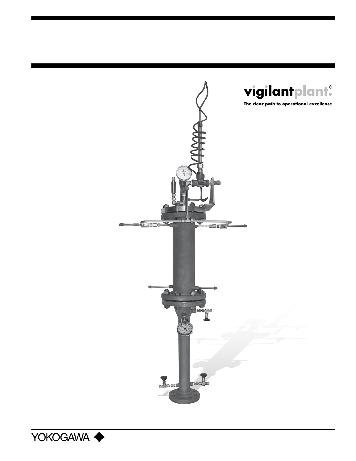
Advance Reux Sampler
Manual
YARS100-SAA
Yokogawa Corporation of America
2 Dart Road, Newnan, Georgia U.S.A. 30265
Tel: 1-800-258-2552 Fax: 1-770-254-0928
IM 11A00V01-01E-A
©Copyright January 2011
1st Edition
Page 2
2
The following safety symbols are used on
the product as well as in this manual.
DANGER
This symbol indicates that an operator
must follow the instructions laid out in
this manual in order to avoid the risks, for
the human body, of injury, electric shock
or fatalities. The manual describes what
special care the operator must take to
avoid such risks.
WARNING
This symbol indicates that an operator
must refer to the instructions in this
manual in order to prevent the instrument
(hardware) or software from being
damaged, or a system failure from
occurring.
This symbol gives information essential
for understanding the operations and
functions.
CAUTION
NOTE
This symbol indicates information that
complements the present topic.
Operating and Maintenance Manual
1. Introduction ........................................................................................................... 4
1.1 Features ................................................................................................. 4
2. General Specications .......................................................................................... 5
3. Theory of Operation ............................................................................................... 6
3.1 Brief History of Reux Samplers .......................................................... 6
3.2 Filter Section ......................................................................................... 6
3.3 Steam Supplement ............................................................................... 6
3.4 Inlet Temperature Section ..................................................................... 6
3.5 Heat Exchanger Section .................................................................... 6-7
3.6 Outlet Temperature Section ................................................................. 7
3.7 Self Acting Temperature Controller ...................................................... 7
3.8 Instrument Air for the Vortex Tube ....................................................... 7
3.9 Vortex Theory of Operation .................................................................. 7
4. Utility Requirements .............................................................................................. 8
4.1 Instrument Air ........................................................................................ 8
4.2 Low Pressure Steam ............................................................................ 8
5. Installation ............................................................................................................. 9
5.1 Mechanical Considerations .................................................................. 9
5.2 Fast Loop Line Size and Response Times .......................................... 9
5.3 Insulation ............................................................................................................. 9
6. Start-Up ............................................................................................................... 10
7. Operation ............................................................................................................. 10
7.1 Vortex Tubes ........................................................................................ 10
7.2 Steam Injection ................................................................................... 10
7.3 Controller ............................................................................................. 10
8. Maintenance ........................................................................................................ 11
8.1 Filter Section and/or Heat Exchanger Cleaning ................................ 11
8.1.1 Heat Exchanger Filter Mesh ............................................................ 11
9. Trouble Shooting .................................................................................................. 11
9.1 Vortex Tubes ........................................................................................ 11
10. Sub-Component Documentation ...................................................................... 12
10.1 Compressed air Line size ................................................................. 12
10.1.1 Compressed air Supply ........................................................ 12
10.1.2 Setting the Vortex Tube ......................................................... 12
10.1.3 Troubleshooting and Maintenance ....................................... 12
10.2 Installation and Maintenance for Control Valves ........................................... 13
10.2.1 General Safety Information ........................................................... 13
10.2.1.1 Warning-Laminated gaskets .......................................... 13
10.2.1.2 Isolation ........................................................................... 13
All Rights Reserved. Copyright © 2011, Yokogawa Electric Corporation. Subject to change without notice. April 2011IM 11A00V01-01E-A
Page 3

10.2.1.3 Pressure .......................................................................... 13
10.2.1.4 Temperature .................................................................... 13
10.2.1.5 Disposal ........................................................................... 13
10.2.2 Installation and Commissioning .................................................... 13
10.3 Supplement Safety Information ...................................................................... 14
10.3.1 Hazardous Liquids or Gases in the Pipeline ................................ 14
10.3.2 Hazardous Environment around the Product............................... 14
10.3.3 The System. ................................................................................... 14
10.3.4 Pressure Systems .......................................................................... 14
10.3.5 Temperature ................................................................................... 14
10.3.6 Tools and Consumables ................................................................ 15
10.3.7 Protective Clothing ........................................................................ 15
10.3.8 Permits to Work ............................................................................. 15
10.3.9 Handling ......................................................................................... 15
10.3.10 Residual Hazards ......................................................................... 15
10.3.11 Freezing ........................................................................................ 15
10.3.12 Disposal ....................................................................................... 15
10.3.13 Returning Products ..................................................................... 15
3
10.4 Installation and Maintenance Instructions for
Temperature Control Valve Systems ............................................................. 15
10.4.1 Safety Information ......................................................................... 15
10.4.2 Installation. ..................................................................................... 16
10.4.3 Display Adjustment ........................................................................ 17
10.4.4 Commissioning .............................................................................. 17
10.5 Supplement Safety Information, Installation
and Maintenance Instructions for AS Temperature
Control Valve Systems .................................................................................. 18
10.5.1 Intended Use .................................................................................. 18
10.5.2 Access ............................................................................................ 18
10.5.3 Lighting ........................................................................................... 18
10.5.4 Hazardous Liquids or Gases in the Pipeline ................................ 18
10.5.5 Hazardous Environment around the Product............................... 18
10.5.6 The System .................................................................................... 18
10.5.7 Pressure Systems .......................................................................... 19
10.5.8 Temperature ................................................................................... 19
10.5.9 Tools and Consumables ................................................................ 19
10.5.10 Protective Clothing ...................................................................... 19
10.5.11 Permits to Work ........................................................................... 19
10.5.12 Handling ....................................................................................... 19
10.5.13 Residual Hazards ......................................................................... 19
10.5.14 Freezing ........................................................................................ 19
10.5.15 Disposal. ...................................................................................... 19
10.5.16 Returning Products ..................................................................... 19
11. Dimensional Drawings .................................................................................20-22
All Rights Reserved. Copyright © 2011, Yokogawa Electric Corporation. Subject to change without notice. April 2011IM 11A00V01-01E-A
Page 4

4
1. INTRODUCTION
Overview
The Advanced Reux Sampler (YARS100) has been developed specically to meet the needs of modern petrochemical
analyzer sampling, especially ethylene cracked gas euents.
1.1 Features
Based on a proven simpler concept, the YARS includes several technologically advanced features outlined below:
• Self-acting temperature controller requiring no electrical power supply – Adjustable across the selected control
range.
• Dual 360o cooling coils section ensures optimal sample cooling
• Outlet lter mesh/screen for mist trap to deter liquid carry over
• Sample outlet over temperature shut-o valve – Factory set for a pre-determined shut-o temperature and
typically with a 10oF span between fully open and fully closed.
• Enhanced, high stability temperature control system design
• High sample ow rate 3-5 liters per minute for reduced lag time
• A multitude of options congured specically for your application
SAFETY should be considered rst and foremost importance when working on the
equipment described in this manual. All persons using this manual in conjunction
with the equipment must evaluate all aspects of the task for potential risks, hazards
and dangerous situations that may exist or potentially exist. Please take appropriate
action to prevent ALL POTENTIAL ACCIDENTS.
CAUTION
All Rights Reserved. Copyright © 2011, Yokogawa Electric Corporation. Subject to change without notice. April 2011IM 11A00V01-01E-A
Page 5
2. GENERIC SPECIFICATIONS
Product development is a continuous policy of Yokogawa and therefore specications may be subject to change without
notice
The following generic specications apply however; please check exact features and model number with serial numbers
on the units provided.
5
A) Process Connection:
Process ange ratings are ASME B16.6-1996
B) Sample Outlet Connection:
Standard 3/8” o.d. Sawgelock® stainless steel
Flow Rate: Typically 3 Lts./min conditioned at 15°C or
4 Lts./min conditioned at 20°C, pending application
Pressure: ΔP across ARS, < 1psi
NOTE
The sample transport line should be heat traced and
insulated to prevent subsequent sample condensation.
C) Mounting:
Vertical on top of customer supplied process isolation
valve for horizontal process line.
NOTE
If mounting on vertical process line, install appropriate
elbow or Y-piece prior to process isolation valve to
ensure ARS mounted in vertical position – Refer to
Installation details.
D) Instrument Air Connection:
Standard 1/2” o.d. Sawgelock®, stainless steel
Supply Pressure: 60-110 psig (~ 54-7.5 Bar)
Flow Rate: Dual 10 SCFM Vortex Tubes: Standard
Dual 15 SCFM Vortex Tubes: Optional
Grade: Clean, Dry, Oil Free and <5μ particles with
–40oC dew point and ISA grade HC free
E) Steam Supplement Connection:
Filter Section
Standard ¼” o.d. Sawgelock®, stainless steel
Pressure: 50-150 psig
Temperature: maximum 238oC
F) Materials of Construction:
Lower lter section: 316 stainless steel
Lower lter mesh: 316 stainless steel knitted, 0.011”
diameter wire
Inlet temperature section: 316 stainless steel
Heat Exchanger: 316 stainless steel
G) Electrical Power supply:
Not Required
H) Self Acting Controller:
Adjustable set-point indicating dial
316 Stainless steel sample wetted parts
Brass body air control valve, high CV
Highly reliable with practically no moving parts
I) Shipping Details
Size: Approximately 56 in (1422 mm) H x 24 in (609
mm) W x 12 in (304 mm)D
Weight: Approximately 110 lbs (49.8 kg) without
optional equipment
All Rights Reserved. Copyright © 2011, Yokogawa Electric Corporation. Subject to change without notice. April 2011IM 11A00V01-01E-A
Page 6

6
3. THEORY OF OPERATION
This section of the manual describes the basic theory of operation, designed to give the user a better understanding and
help in operation and maintenance.
3.1 Brief History of Reux Samplers
The concept of the Reux Sampler was introduced in mid 1970’s and until the inception of the Advanced Reux Sampler
(YARS), it had changed very little. Process analysis needs during the mid 1970’s were not as critical as they are now and
consequently, the Reux Samplers designed previously no longer meet today’s demands that are more stringent. The
reux sampler was originally designed to overcome the problem of constantly plugging sample probes installed on the
Transfer Line Exchangers (TLE) of ethylene cracking furnace euents. This high temperature cracked gas euent is high
in particulate and condensables (moisture and heavy hydrocarbons) content and therefore prone to plugging. The idea
that the condensables could be used to backwash a particulate lter was conceived and a Reux Sampler was then
developed. A simple lter mesh was used to trap the particulate matter.
3.2 Filter Section
The lower section of the YARS is for particulate ltration and provides some primary sample cooling. Typically ange
mounted directly to a customer supplied process isolation valve and ange mounted to the heat exchanger section of
the YARS. The lter media is nominally stainless steel wire mesh that traps any particulate matter such as coke from the
ethylene furnaces and/or catalyst nes. During normal operation, the temperature at the lter section outlet should be
in the order of 120oF (50oC), indicating a balanced reuxing condition is established. This lter section is cooled by the
condensate that has dropped out from the heat exchanger mounted directly above the lter. The condensate also acts as
a trap for ner particulate matter. In certain environmental conditions where sub-zero temperatures are anticipated, it may
be desirable to insulate the lter section. This will prevent premature condensing and allow for a balanced reuxing action.
3.3 Steam Supplement
For the YARS to function reliably there must be sucient quantity of condensable media in the sample. For applications
that have high particle loading and limited condensables present, steam should be added at the inlet. The YARS lter
section has a steam inlet facility located at the inlet. A suitably rated needle valve is provided for regulating a nominal ow
of steam in to the lter section via an inverted tube such that the steam is directed up in to the lters. Note that the steam
is added directly to the sample and therefore the composition will be aected the H2O addition. As each application has
many dierent operating parameters, there are no specic settings for the quantity of steam addition and each application
is set-up individually.
3.4 Inlet Temperature Section
Mounted between the lter and heat exchanger section is the inlet temperature thermowell. As standard, a suitable
temperature gauge is installed in the thermowell. The purpose of temperature measurement at this point in the YARS is
to help establish the correct temperature gradient required for reuxing. The two undesirable conditions within the ler
section are as below:
• Temperature reading too high – will cause the heat exchanger to work excessively and indicates a problem
elsewhere in the system
• Temperature reading too low – will cause the condensable media to dropout early in the lter section and not
provide proper lter cleansing by reux.
When troubleshooting the YARS, consider the correct temperature at this point.
3.5 Heat Exchanger Section
This is truly unique to the YARS in many respects. This section provides the cooling of the sample and is most critical to
the overall operation. As the sample gas rises from the lter section, through the inlet temperature section, it is channeled
in to the heat exchanger chamber. The sample gas rises through a chamber in which the cooling coils are concentrically
mounted. The design of the heat exchanger is such that maximum surface area contact between the cooling coils and
All Rights Reserved. Copyright © 2011, Yokogawa Electric Corporation. Subject to change without notice. April 2011IM 11A00V01-01E-A
Page 7
the sample gas is achieved. There are two cooling coils located in the same heat exchanger chamber, which helps
provide more accurate and ecient cooling. In the head-space of the heat exchanger, a stainless steel ne lter mesh is
installed to act as a mist trap and nal liquid sample droplet trap prior to existing the sampler. Flow of the cooling media
through each coil is automatically controlled to ensure a constant outlet temperature is maintained. The sample is normally
saturated at the outlet temperature and pressure. The cooling media is supplied by vortex air cooler(s) via the self-acting
controller.
3.6 Outlet Temperature Section
Located on the outlet of the heat exchanger is the outlet temperature indicator. For self-acting controller units, a
temperature sensor is installed. The self-acting temperature controller is located (screwed) directly in to the top of the
heat exchanger in to the headspace area. This provides the most accurate temperature reading and control of the actual
sample outlet temperature. The purpose of temperature measurement at this point in the YARS is to control the nal outlet
temperature (or maximum dewpoint). Depending upon the application, this outlet temperature may be typically between
41-80oF (5-27oC).
3.7 Self Acting Temperature Controller
The operation and maintenance of the adjustable self-acting temperature controller is described herein.
3.8 Instrument Air for the Vortex Tube
The standard media used by the Vortex air tube(s) is ISA grade Instrument air. It is possible to change the cool air
outlet temperature by adjusting the recessed screw (needle valve) located in the hot air exhaust. A counter-clockwise
adjustment of the valve will produce colder temperatures while a clockwise adjustment will produce warmer temperatures.
This ability to adjust the temperature may be considered when ne-tuning the temperature control system to ensure
optimum temperature stability. The performance of the Vortex tubes is also based on the incoming instrument air
temperature. For more ecient operation, avoid direct sun light (and other heat emitting sources) when running the air line.
7
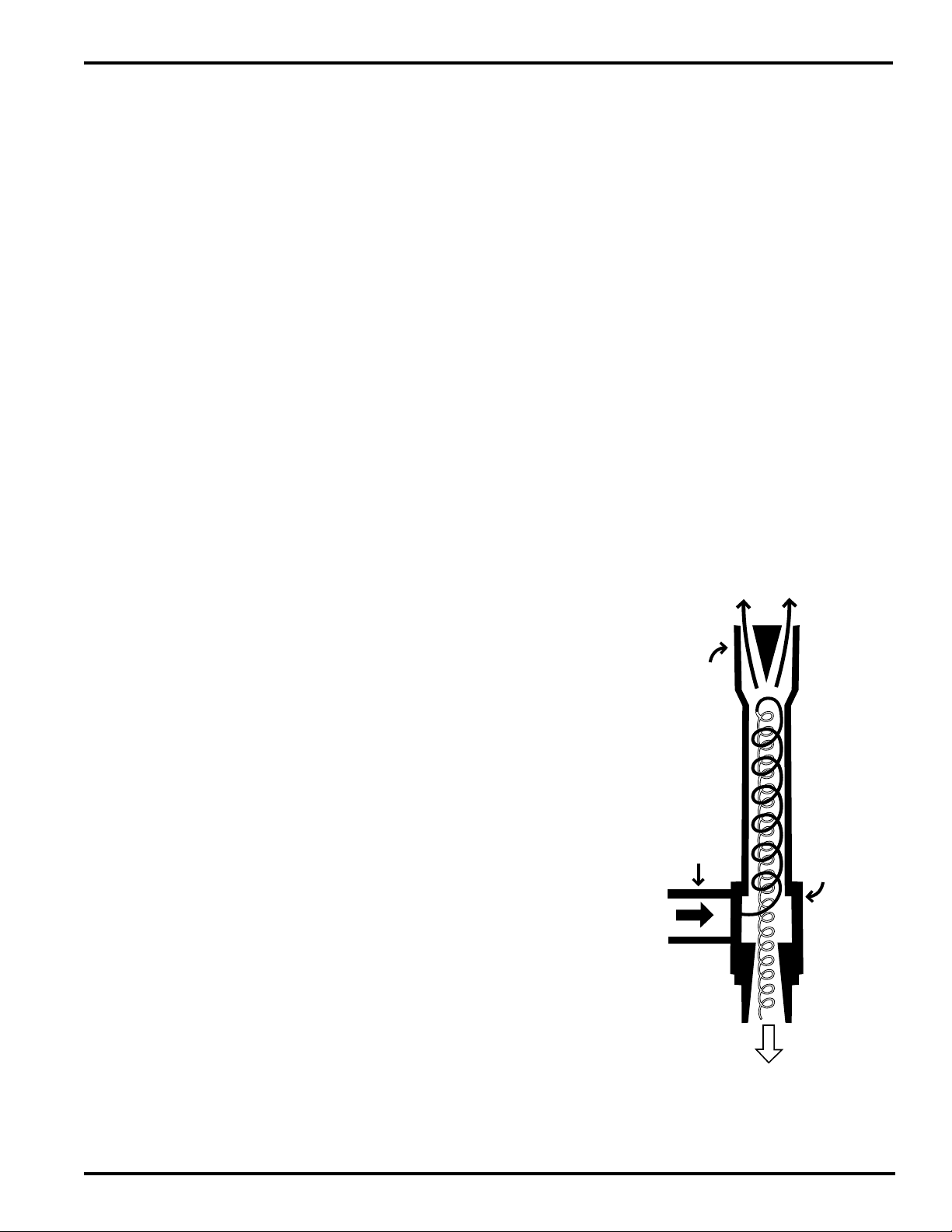
3.9 Vortex Theory of Operation:
Vortex tubes are simple devices that contain no moving parts and
therefore may be used as a reliable device for generating a cold air supply.
Compressed air (clean, dry, ISA Grade) will enter the cylindrical chamber
(to the left of the diagram) and is caused to rotate internally. This rotating
air moves down the inner walls of the hot air exhaust chamber at extremely
high velocity. When exiting the hot exhaust (to the top of the diagram), a
portion of the air is directed back through the center at lower speed than
the exiting air. Heat transfer from the inner, slow moving air to the exiting,
fast moving air causes cold air to be generated. This cold air exits via the
cold air exhaust (shown at the bottom of the diagram).
Vortex tubes produce less air ow at colder temperatures and have less
BTUH capacity. Tubes are available in a variety of sizes depending upon
the application. Maximum eciency will be achieved when operating
at 100 psig instrument air pressure and while they can operate at lower
pressure, the eciency will be less (typically 60% ecient at 55 psig)
All Rights Reserved. Copyright © 2011, Yokogawa Electric Corporation. Subject to change without notice. April 2011IM 11A00V01-01E-A
Page 8
8
4. UTILITY REQUIREMENTS
Section 2 – General Specication listed above denes the required utilities needed for YARS operation. Also, refer to the
General Installation drawing provided specically for the YARS by serial number for the hook-up details.
4.1 Instrument Air
The media used by the Vortex air tube(s) is ISA grade Instrument air. Plant Nitrogen may be used in place of the air,
provided it meets the required pressure and ow demands of the YARS. The air shall be clean, dry (-40oC dew point),
oil free and contain particles <5µ. The instrument air pressure at the YARS shall be 60-100 psig (~ 4-7 Barg). Failure to
use a lter will cause potential freezing and clogging of the compressed air path inside the Vortex Tube. Filter elements
must be changed on a regular basis. Frequency of change is determined by the conditions of the compressed air
supply.
At pressure less than this, the Vortex tube performance declines signicantly and may be unable to provide the required
quantity of cooling air. Any instrument air-line run to the YARS in the eld should be 1/2” o.d. to ensure adequate ow at
the desired pressure.
Electronically controlled samplers use two vortex tubes, each typically with a 4 SCFM ow capacity (Check Data Sheets
for your installed model) however, the actual air demand during normal operation will vary depending on the changing
process and climatic conditions at each site.
CAUTION
• COMPRESSED AIR COULD CAUSE DEATH, BLINDNESS OR INJURY
• DO NOT OPERATE A VORTEX TUBE AT AIR PRESSURES ABOVE150PSIG (10.3 BARG)
• DO NOT OPERATE A VORTEX TUBE AT LINE TEMPERATURES ABOVE 110OF (43OC)
• AVOID DIRECT CONTACT WITH COMPRESSED AIR
• DO NOT DIRECT COMPRESSED AIR AT ANY PERSON
• WHEN USING COMPRESSED AIR, WEAR SAFETY GLASSES AND SIDE SHIELDS
The performance of the Vortex tubes is also based on the incoming instrument air temperature and therefore, for more
ecient operation, avoid direct sun light (and other heat emitting sources) when running the air-line.
4.2 Low Pressure Steam
The sampler is equipped with low-pressure steam injection valve located in the lower lter section. Steam may be used
either as an addition at the inlet (for assisted reux action), or for cleansing through either the inlet or outlet.
NOTE
Do not use steam temperatures in excess of 232oC (450oF).
Ensure the needle valves are closed prior to connecting the steam supply and ensure the steam supply line is adequately
insulated. Connect the steam supply directly to the needle valve supplied with the sampler.
NOTE
WHEN OPERATING WITH STEAM, NOTE THAT SURFACES MAY BE EXTREMELY HOT AND CAN CAUSE SEVERE BURNS
AND OTHER PERSONAL INJURIES – ADHERE ALL SAFETY PROCEDURES APPLICABLE AT SITE FOR STEAM SERVICES
- FAILURE TO DO SO COULD RESULT IN INJURY OR DEATH.
All Rights Reserved. Copyright © 2011, Yokogawa Electric Corporation. Subject to change without notice. April 2011IM 11A00V01-01E-A
Page 9
5. INSTALLATION
5.1 Mechanical Considerations
Typically, the YARS will be subject to large vibration conditions and therefore a sound mechanical installation is required.
While ange mounting to the customer supplied process isolation valve provides an installation, it is also recommended
that the upper section of the YARS be secured mechanically. The heat exchanger and controller give the YARS ‘top-heavy’
properties that should be considered during installation.
It is also desirable to have ready access to the unit such that routine maintenance checks can be made on the operation
of the unit in a safe manner.
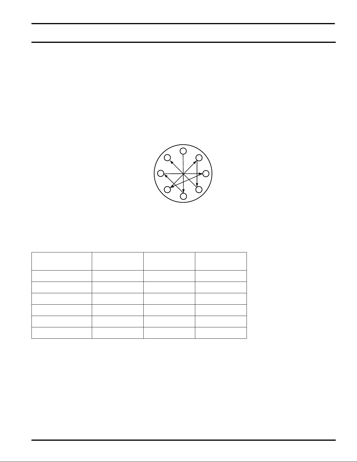
Ensure that an appropriate gasket is used between the ange mounting faces and when tightening the ange mounting
bolts to the process isolation valve, please ensure that the correct torque is applied (typically 100 foot pounds for a 2”
300# ange). As with any anged bolt tightening, ensure that the correct sequence of tightening is followed (typically as
shown below):
1
8
6
9
3
5
2
4
7
5.2 Fast Loop Line Size and Response Times
The following table may be used when estimating sample line sizes, response times and resultant pressure drop through
the line. These calculations are based on a typical ethylene cracked gas euent sample and should be used for estimating
purposes only:
Sample Line Size
Stainless Tube
¼” 200’ 1.5 39
¼ 200’ 3 19
¼ 200’ 4.5 13
3
/8” 200’ 1.5 108
3
/8” 200’ 3 54
3
/8” 200’ 4.5 34
Sample Line
Length
Sample Flow
Rate Lts/min
Response Time
Seconds
All Rights Reserved. Copyright © 2011, Yokogawa Electric Corporation. Subject to change without notice. April 2011IM 11A00V01-01E-A
Page 10

10
5.3 Insulation
The heat exchanger and top ange section of the YARS MUST always be insulated by at least two inches (obtained from
a local supplier). This will reduce the inuences of ambient air temperature uctuations and cause the heat exchanger to
operate more eciently. Insulation should be installed at site after installation and leak testing and should be congured for
possible future maintenance and access.
It is generally required to have the lter section insulated only when ambient temperatures fall below 32oF (0oC). Insulation
should conform to appropriate site standards. This insulation may not be required during hot summer months however
only on-site experience can determine the exact insulation requirements for the lter section.
All Rights Reserved. Copyright © 2011, Yokogawa Electric Corporation. Subject to change without notice. April 2011IM 11A00V01-01E-A
Page 11

6. START-UP
1. Ensure the installation has been carried out in accordance with the unit requirements and any appropriate regulations/
standards applicable for the site.
2. Turn on instrument air supply and adjust pressure as required. Check for any leaks in the system.
3. Check for any leaks in the process and sample line connection. Rectify Accordingly.
4. Insulate the heat exchanger section, including the top ange assembly and over-temp shut o valve on top of the
heat exchanger.
5. As the system begins to cool down, slowly allow sample ow through the sampler. Increase gradually so that
excessive temperature does not cause the sample over temperature valve to shut-o ow. It may be necessary to
increase the sample ow in gradual steps (1 ltr/min increase every 10 minutes). This will allow the sample to maintain
cooling control on the sample. A sudden step change from 0 to 5 ltr/min may temporarily exceed the cooling capacity
and cause Over Temperature shut-o.
6. After the system has stabilized in temperature, note the sample outlet temperature reading. This should be within +/2oC (+/-6.5oF) of the desired sample outlet temperature. Adjust outlet temperature at the control dial as required to
reach the desired set-point.
NOTE
Proper insulation of the entire heat exchanger and outlet section will ensure optimal performance and temperature
stability. Failure to do so will result in poor performance and temperature drift due to ambient air temperature uctuations.
11
7. OPERATION
During normal operation, the YARS will function automatically.
7.1 Vortex Tubes
Adjustment to the Vortex Tube can be made to vary to temperature of the cooling air provided to the heat exchangers. A
counter-clockwise adjustment of the brass needle valve (recessed in the hot exhaust) will produce colder air, while turning
the needle valve in a clockwise direction produces warmer air.
7.2 Steam Injection
Depending upon the site process conditions, it may or may not become necessary to continuously inject a small volume
of low pressure steam. With the steam supply correctly installed, open the needle valve ½ turn allowing a small volume of
steam in to the sample. Note the sample owrate after steam injection to be sure that the steam does not over pressure
the sample and interfere with the sample ow. If the ½ turn does not produce sucient additional reux action, then adjust
a further ½ turn, again observing the sample ow. This procedure can be carried out several times until correct reux
action occurs without interfering with sample ow. Note, excessive steam may cause the lter section ,and consequently
the heat exchanger to become too hot, thereby impairing temperature control.
7.3 Controller
The self-acting controller is adjustable. Refer to the attached for additional details.
All Rights Reserved. Copyright © 2011, Yokogawa Electric Corporation. Subject to change without notice. April 2011IM 11A00V01-01E-A
Page 12

12
8. MAINTENANCE
When set-up and operated correctly, the YARS will require no routine maintenance other than lter cleansing, normally
during a routine de-coke cycle and/or shut-down.
8.1 Filter Section and/or Heat Exchanger Cleaning
To avoid lter section plugging, it is recommended that a routine steam clean be carried out on the lter section. Actual
site operating conditions will determine the optimal cleansing period and duration and this may typically be required every
3-4 months.
The lter section may be cleaned using steam and or any site approved solvents. After cleaning and/or replacement of
lter mesh, ensure any traces of cleaning solvents have been removed to avoid any analytical cross contamination when
the unit is returned to service.
The heat exchanger section should not ordinarily require any cleaning, however it is possible to introduce steam through
the sample outlet port located at the top exit of the sampler. Ensure the outlet temperature indicator is isolated from the
steam during heat exchanger cleansing.
If required, a replacement lter cartridge may be installed – Refer to factory for details.
When using steam, ensure all appropriate safety precautions are OBSERVED ~ avoid accidental burns!
CAUTION
8.1.1 Heat Exchanger Filter Mesh
Located inside the top heat exchanger section of the sampler is a 4” lter mesh pad assembly. This acts as a de-misting
pad and nal heat transfer/ltration device prior to sample outlet. It is constructed of stainless steel and may be steam
cleaned or replaced as needed. Refer to factory for replacement lter.
8.1.2 Filter Section and Sample Outlet Temperature Gauge
Please follow the manufactures recommendations for calibration and adjustment of the lter section temperature gauge.
9. TROUBLE SHOOTING
The following may assist in trouble shooting and fault diagnostics:
9.1 Vortex Tubes
Insucient air ow can be caused by the following:
1. Undersized compressed air supply line.
2. Compressed air line pressure too low.
3. Insucient compressed air volume (SCFM).
4. Partial or complete blockage of internal compressed air path due to dirt, etc.
5. Compressed air line temperature too high.
6. Loose cold cap (if disassembled for cleaning).
All Rights Reserved. Copyright © 2011, Yokogawa Electric Corporation. Subject to change without notice. April 2011IM 11A00V01-01E-A
Page 13

13
10. SUB-COMPONENT DOCUMENTATION
This section contains sub-component manufacturers information and supporting documentation that may be of use to
operators.
10.1 Compressed Air Line Sizes
Compressed air lines should be sized to hold pressure drops to a minimum. So not used restrictive ttings such as quick
connects. They can “starve” the Vortex Tube by causing line pressure drop. The following chart gives suggested line sizes
for pipe and hose.
Line Sizes for Runs Up To:
10 FT
(3 M)
Pipe Hose Pipe Hose Pipe Hose
1/4” 3/8” 3/8” 1/2” 1/2” 5/8”
10 - 50 FT
(3 - 15 M)
50 - 100 FT
(15 - 30.5M)
10.1.1 Compressed Air Supply
For best performance, use line pressure 80 to 100 PSIG (5.5 – 6.9 BAR). Vortex Tubes are rated in SCFM (SLPM) at 100
PSIG (6.9 BAR) supply pressure.
With proper ltration and separation for dirt, moisture and oil from the compressed air supply, the Vortex Tube will run for
years with no maintenance required. Use a 25 micron or smaller lter separator that is sized to SCFM (SLPM) rating of the
Vortex Tube.
To prevent problems associated with oil, use an appropriate Oil Removal Filter for Vortex Tubes up to 30 SCFM (850
SLPM) . The oil removal lter should be used downstream from the automatic drain lter separator. Filter should be used
within 10 to 15 ft ( 3 to 4.6 m ) of each Vortex Tube.
For Replacement or Repair lter and regulator parts contact Yokogawa.
10.1.2 Setting the Vortex Tube
Hot and cold temperatures produced by a Vortex Tube are innitely variable by adjusting the slotted valve at the hot air
exhaust. Opening the valve reduces the cold airow and the cold air temperature, Closing the valve increases the cold
airow and the cold air temperature.
Set the Vortex Tube with a thermometer. To measure temperature accurately, it should be inserted into the cold muer or
a piece of tubing on the cold end exhaust.
10.1.3 Troubleshooting & Maintenance
If the Vortex Tubes Does Not perform properly, check for these common problems:
1.) Loosed Cold Cap or Cold Muer- A loosed cold cap or cold muer will cause poor performance. Make sure it is tight.
2.) Inlet Pressure- Low inlet pressure supply will cause poor performance. Measure the pressure at the compress air
All Rights Reserved. Copyright © 2011, Yokogawa Electric Corporation. Subject to change without notice. April 2011IM 11A00V01-01E-A
Page 14

14
inlet of the Vortex Tube while it is operating. Restrictions in the compressed air supply line can cause excessive
pressure drops and deteriorate performance.
3.) Inlet Temperature- A Vortex Tube provides a temperature drop from supply air temperature. In some cases, the
supply air is warmer than ambient air due to compressed air lines running across ceilings, near furnaces, direct sun,
etc. In this case, the cold air may be warmer than anticipated and adequate refrigeration may not be available for the
application.
4.) No Cold Flow- If the Vortex Tube is operated continuously for an extended period of time and is set for more than
a 50ºF (25ºC) drop from the compressed air temperature, the cold end may freeze, blocking the cold outlet. If this
happens, any one of the following will correct the problem:
a. Blow air (use an air gun) into the cold end with the Vortex Tube o.
b. Turn the Vortex Tube o for a few minutes. It will thaw.
c. Use dry air with an atmospheric dew point of -40º or less.
5.) Back Pressure - The performance of a Vortex Tube deteriorates with back pressure on the cold air exhaust. Pressure
up to 2 PSGIG (0.1 BAR) will not change performance. 5 PSIG (0.3 BAR) will change performance by approximately
5ºF (2.8ºC). If cold air ducting is used, the total-cross-sectional area should be equal or greater than the area of the
Vortex Tube cold air exhaust.
10.2 Installation and Maintenance Instructions for Control Valves
10.2.1 General Safety Information
These products are designed and constructed to withstand the forces encountered in normal use. The normal operation
and limits for temperature and pressures are stated in the General Specications in section 2.
Safe operation of these units can only be guaranteed if they are properly installed, commissioned and maintained by a
qualied person in compliance with the operating instructions. General installation and safety instructions for pipeline and
plant construction, as well as the proper use of tools and safety equipment must also be complied with.
10.2.1.1 Warning - Laminated gaskets
The metal foil sheet used to reinforce gaskets is very thin and sharp. Care should be taken when handling to avoid
the possibility of cuts or lacerations to ngers or hands.
10.2.1.2 Isolation
Consider whether closing isolating valves will put any other part of the system or personnel at risk. Dangers might
include; isolation of vents and protective devices or alarms. Ensure isolation valves are turned oft in a gradual way to
avoid system shocks.
10.2.1.3 Pressure
Before attempting any maintenance consider what is or may have been in the pipeline. Ensure that any pressure
is isolated and safely vented to atmospheric pressure before attempting to maintain the product, this is easily
achieved by tting Yokogawa depressurization valves (see separate literature for details). Do not assume that the
system is depressurized even when a pressure gauge indicates zero.
10.2.1.4 Temperature
Allow time for temperature to normalize after isolation to avoid the danger of burns and consider whether protective
clothing (including safety glasses) is required.
10.2.1.5 Disposal
These products are recyclable. No ecological hazard is anticipated with the disposal of these products providing
due care is taken.
All Rights Reserved. Copyright © 2011, Yokogawa Electric Corporation. Subject to change without notice. April 2011IM 11A00V01-01E-A
Page 15

15
10.2.2 Installation and Commissioning
NOTE
Before starting any installation observe the “Safety information” Section 10.2.1.
The valve should always be tted in a horizontal pipeline with the ow in the direction indicated by the arrow marked on
the body with the sensor in a vertical plane below the pipeline as shown in Fig. 1 .(SA control system). Valves should be
mounted in the pipeline in accordance with the actuator installation and Maintenance Instructions.
A suitable strainer should always be tted upstream of the valve. Additionally on steam installations a separator should be
tted before the valve, plus a steam trap set on applications where condensate may accumulate upstream of the valve
WARNING
The control system actuator must be securely connected to the valve via the screwed connection on the bottom of the
valve and the half union coupling on the actuator before any uid is allowed to pass through the valve. Similarly, the
actuator should not be disconnected from the valve until the valve itself. is fully isolated
It is important that line stresses i.e. expansion or inadequate supporting of the pipe are not imposed on the valve body.
If the valve is properly sized for the duty it has to perform it will often be smaller than the pipeline. This is particularly so
where the medium passing through the valve is steam, in which case any reduction in line size should be made using
eccentric reducers. The piping on both upstream and downstream sides of the valve must be of ample size to avoid
undue pressure drop in the line and any reduction to meet the size of the valve should be made close to the valves as
shown in Fig. 1
It is advisable to protect the valve by tting a strainer on the upstream side. By tting the strainer on its side where the
medium is steam you will prevent the body lling with water which would reduce the screening area.
In most steam installations~ water formed by condensation due to radiation losses will be present in the upstream pipeline
and should be removed by an adequate drain point and trap, as shown in Fig. 1.
NOTE
For commissioning instructions refer to the Operation, Installation and Maintenance Instructions, covering Yokogawa
control systems.
10.3 Safety Information
10.3.1 Hazardous Liquids or Gases in the Pipeline
Consider what is in the pipeline or what may have been in the pipeline at some previous time. Consider: ammable
materials, substances hazardous to health, extremes of temperature.
10.3.2 Hazardous Environment around the Product
Consider: explosion risk areas, lack of oxygen (e.g., tanks, pits), dangerous gases, extremes of temperature, hot surfaces,
re hazard (e.g. during welding), excessive noise, moving machinery.
10.3.3 The System
Consider the eect on the complete system of the work proposed. Will any proposed action (e.g. closing isolation valves,
electrical isolation) put any other part of the system or any personnel at risk?
DANGER
Dangers might include isolation of vents or protective devices or the rendering ineective of controls or alarms. Ensure
isolation valves are turned on and o in a gradual way to avoid system shocks.
All Rights Reserved. Copyright © 2011, Yokogawa Electric Corporation. Subject to change without notice. April 2011IM 11A00V01-01E-A
Page 16

16
10.3.4 Pressure Systems
Ensure that any pressure is isolated and safely vented to atmospheric pressure. Consider double isolation (double block
and bleed) and the locking or labeling of closed valves. Do not assume that the system has depressurized even when the
pressure gauge indicates zero.
10.3. 5 Temperature
Allow time for temperature to normalize after isolation to avoid danger of burns.
10.3.6 Tools and Consumables
Before starting work ensure that you have suitable tools and/or consumables available. Use only genuine Yokogawa
replacement parts.
10.3.7 Protective Clothing
Consider whether you and/or others in the Vicinity require any protective clothing to protect against the hazards of, for
example, chemicals, high/low temperature, radiation, noise, falling objects, and dangers to eyes and face.
10.3.8 Permits to Work
All work must be carried out or be supervised by a suitably competent person. Installation and operating personnel should
be trained in the correct use of the product according to the Installation and· Maintenance Instructions. Where a formal
‘permit to work’ system is in force it must be complied with. Where there is no such system, it is recommended that a
responsible person should know what work is going on and, where necessary, arrange to have an assistant whose primary
responsibility is safety.
Post ‘warning notices’ if necessary.
10.3.9 Handling
Manual handling of large and/or heavy products may present a risk of injury. Lifting, pushing, pulling, carrying or
supporting a load by bodily force can cause injury particularly to the back. You are advised to assess the risks taking
into account the task, the individual, the load and the working environment and use the appropriate handling method
depending on the circumstances of the work being done,
10.3.10 Residual Hazards
In normal use the external surface of the product may be very hot. If used at the maximum permitted operating conditions
the surface temperature of some products may reach temperatures of 300ºC.
Many products are not self-draining. Take due care when dismantling or removing the product from an installation (refer to
‘Maintenance instructions’).
10.3.11 Freezing
Provision must be made to protect products which are not self-draining against frost damage in environments where they
may be exposed to temperatures below freezing point.
10.3.12 Disposal
Unless otherwise stated in the Installation and Maintenance Instructions, this product is recyclable and no ecological
hazard is anticipated with its disposal providing due care is taken.
10.3.13 Returning Products
Customers and stockiest are reminded that under EC Health, Safety and Environment Law, when returning products to
Yokogawa they must provide information on any hazards and the precautions to be taken due to contamination residues
or mechanical damage which may present a health, safety or environmental risk. This information must be provided
in writing including Health and Safety data sheets relating to any substances identied as hazardous or potentially
hazardous.
All Rights Reserved. Copyright © 2011, Yokogawa Electric Corporation. Subject to change without notice. April 2011IM 11A00V01-01E-A
Page 17

17
10.4 Installation and Maintenance Instructions for
Temperature Control Valve Systems
10.4.1 Safety Information
This product is designed and constructed to withstand the force encountered in normal use. Use of the product for any
purpose other than as a temperature controller could cause Injury or fatality to personnel.
NOTE
This product contains Kerosene which is highly inammable.
10.4.2 Installation
Check that the control system supplied is of the temperature range required. It is important that the whole of the
temperature sensing area of the sensor is fully immersed in the uid being controlled, see Fig. 1.
WARNING
The sensor must not be subjected to mercury or ammonium salts.
The sensors can be held in a screwed nipple by means of a compression ring. Screw the nipple into the boss provided on
the plant, thread the union nut and compression ring over the sensor. Insert the sensor fully into the nipple and tighten up
the nut and compression ring. Do not over tighten. Where the sensors are used in conjunction with a pocket, either to allow
easy withdrawal or as a protection against corrosion, the separate screwed nipple is dispensed with and the union nut and
compression ring attached directly to the top of the pocket. Therefore insert the pocket in place of the screwed nipple.
When using a special long pocket with the SA122 or SA123 sensor, the screwed nipple, compression ring and nut are
dispensed with and a rubber sealing bung provided, which is tted over the capillary and slid into place to secure the sensor
into the pocket. Screw the pocket into place, and then feed the sensor bulb to the bottom of the pocket, using the rubber
bung to seal the top.
When using a pocket it is advisable to ll the gap between the pocket and the sensor with a heat conducting medium such
as oil, but when using a special fang pocket in conjunction with the SA122 or SA123 sensors it should not be lled above
the top of the sensor. The adjustment mechanism should not be subjected to an ambient temperature above 50°C (122°F).
The capillary tube between the sensor and the valve must be run and supported in such a way that it wilt not become
damaged. Avoid all sharp bends.
All Rights Reserved. Copyright © 2011, Yokogawa Electric Corporation. Subject to change without notice. April 2011IM 11A00V01-01E-A
Page 18

18
10.4.3 Display Adjustment
The adjustment head provided (Figure 1), enables the set
temperature to be raisd or lowered, one the drive screw ‘C’
has been engaged.
To make any adjustment the blue knob is turned clockwise to
lower the temperature, and counterclockwise to increase it.
After setting, if desired, the drive screw can be disengaged
by prying out the black plastic cap ‘B’ with a small at-head
screwdriver, via the slot provided, remove the 3 mm A/F allen
headed drive screw ‘C’ and stow in the knob, then replace the
black cap.
The adjustment knob will now spin freely without changing the
temperature setting.
B
C
10.4.4 Commissioning
Reference Figure 2, opposite, for the following instructions:
Adjust to the desired setting by turning the knob clockwise to
lower the temperaure and counterclockwise to increase it.
After setting the plant to work, compare the thermometer
reading with the scale reading on the temperature control
reading. This may be found to dier by a few degrees. If
precise indication is require it can be adjusted by resetting the
scale as follows.
1. Loosen the screw holding the sleeve scale in place and
adjust the sleeeve by rotating it until the scale reading
matches the actual temperature.
2. Tighten the screw until it holds the scale rmly in place
without over tightening (it only needs a light touch as it
is for location only).
Adjustment head (knob)
Fig. 1
Screw
Fig. 2
All Rights Reserved. Copyright © 2011, Yokogawa Electric Corporation. Subject to change without notice. April 2011IM 11A00V01-01E-A
Knob
Sleeve
scale
Page 19

10.5 Supplementary Safety Information, Installation and Maintenance
Instructions for SA Temperature Control Systems:
Safe operation of these products can only be guaranteed if they are properly installed, commissioned, used and
maintained by qualied personnel 10.6 in compliance with the operating Instructions. General installation and safety
instructions for pipeline and plant construction, as well as the proper use of tools and safety equipment must also be
complied with.
10.5.1 Intended Use
Referring to the Installation and Maintenance Instructions, name-plate and Technical Information Sheet, check that the
product is suitable for the intended use/application. The products listed below comply with the requirements of the
European Pressure Equipment Directive 97/23/EC and fall within category ‘SEP’. It should be noted that products within
this category are required by the directive now to carry the CE mark.
i) The products have been specically designed for use on steam water and other non-hazardous uids which are
in Group 2 of the above mentioned Pressure Equipment Directive. The products’ use on other uids may be
possible but, if this is contemplated, Yokogawa should be contacted to conrm the suitability of the product for the
application being considered.
ii) Check material suitability, pressure and temperature and their maximum and minimum values. If the maximum
operating limits of the product are lower than those of the system in which it is being tted, or if malfunction of the
product could result in a dangerous overpressure or over temperature occurrence, ensure a safety device is included
in the system to prevent such over-limit situations.
19
iii) Determine the correct installation situation and direction of uid ow.
iv) Yokogawa products are not intended to withstand external stresses that may be induced by any system to which
they are tted. It is the responsibility of the installer to consider these stresses and take adequate precautions to
minimize them.
v) Remove protection covers from all connections before installation.
10.5.2 Access
Ensure safe access and if necessary a safe working platform (suitably guarded) before attempting to work on the product..
Arrange suitable lifting gear if required.
10.5.3 Lighting
Ensure adequate lighting, particularly where detailed or intricate work is required
10.5.4 Hazardous Liquids or Gases in the Pipeline
Consider what is in the pipeline or what may have been in the pipeline at some previous time. Consider: ammable
materials, substances hazardous to health, extremes of temperature.
10.5.5 Hazardous Environment around the Product
Consider: explosion risk areas, lack of oxygen (e.g., tanks, pits), dangerous gases, extremes of temperature, hot surfaces,
re hazard (e.g. during welding), excessive noise, moving machinery.
10.5.6 The System
Consider the eect on the complete system of the work proposed. Will any proposed action (e.g. closing isolation valves,
electrical isolation) put any other part of the system or any personnel at risk?
Dangers might include isolation of vents or protective devices or the rendering ineective of controls or alarms. Ensure
isolation valves are turned on and o in a gradual way to avoid system shocks.
All Rights Reserved. Copyright © 2011, Yokogawa Electric Corporation. Subject to change without notice. April 2011IM 11A00V01-01E-A
Page 20

20
10.5.7 Pressure Systems
Ensure that any pressure is isolated and safely vented to atmospheric pressure. Consider double isolation (double block
and bleed) and the locking or labeling of closed valves. Do not assume that the system has depressurized even when the
pressure gauge indicates zero.
10.5.8 Temperature
Allow time for temperature to normalize after isolation to avoid danger of burns.
10.5.9 Tools and Consumables
Before starting work ensure that you have suitable tools and/or consumables available. Use only genuine Yokogawa
replacement parts.
10.5.10 Protective Clothing
Consider whether you and/or others in the Vicinity require any protective clothing to protect against the hazards of, for
example, chemicals, high/low temperature, radiation, noise, falling objects, and dangers to eyes and face.
10.5.11 Permits to Work
All work must be carried out or be supervised by a suitably competent person. Installation and operating personnel should
be trained in the correct use of the product according to the Installation and· Maintenance Instructions. Where a formal
‘permit to work’ system is in force it must be complied with. Where there is no such system, it is recommended that a
responsible person should know what work is going on and, where necessary, arrange to have an assistant whose primary
responsibility is safety.
Post ‘warning notices’ if necessary.
10.5.12 Handling
Manual handling of large and/or heavy products may present a risk of injury. Lifting, pushing, pulling, carrying or
supporting a load by bodily force can cause injury particularly to the back. You are advised to assess the risks taking
into account the task, the individual, the load and the working environment and use the appropriate handling method
depending on the circumstances of the work being done,
10.5.13 Residual Hazards
In normal use the external surface of the product may be very hot. If used at the maximum permitted operating conditions
the surface temperature of some products may reach temperatures of 350ºC.
Many products are not self-draining. Take due care when dismantling or removing the product from an installation (refer to
‘Maintenance instructions’).
10.5.14 Freezing
Provision must be made to protect products which are not self-draining against frost damage in environments where they
may be exposed to temperatures below freezing point.
10.5.15 Disposal
Unless otherwise stated in the Installation and Maintenance Instructions, this product is recyclable and no ecological
hazard is anticipated with its disposal providing due care is taken.
10.5.16 Returning Products
Customers and stockiest are reminded that under EC Health, Safety and Environment Law, when returning products to
Yokogawa they must provide information on any hazards and the precautions to be taken due to contamination residues
or mechanical damage which may present a health, safety or environmental risk. This information must be provided in
All Rights Reserved. Copyright © 2011, Yokogawa Electric Corporation. Subject to change without notice. April 2011IM 11A00V01-01E-A
Page 21

11 DIMENSION DRAWINGS
writing including Health and Safety data sheets relating to any substances identied as hazardous or potentially hazardous.
21
All Rights Reserved. Copyright © 2011, Yokogawa Electric Corporation. Subject to change without notice. April 2011IM 11A00V01-01E-A
Page 22

22
11 Dimension Drawings (continued)
All Rights Reserved. Copyright © 2011, Yokogawa Electric Corporation. Subject to change without notice. April 2011IM 11A00V01-01E-A
Page 23

11 Dimension Drawings (continued)
23
All Rights Reserved. Copyright © 2011, Yokogawa Electric Corporation. Subject to change without notice. April 2011IM 11A00V01-01E-A
Page 24

24
Notes
_____________________________________________________________________________________________________________
_____________________________________________________________________________________________________________
_____________________________________________________________________________________________________________
_____________________________________________________________________________________________________________
_____________________________________________________________________________________________________________
_____________________________________________________________________________________________________________
_____________________________________________________________________________________________________________
_____________________________________________________________________________________________________________
_____________________________________________________________________________________________________________
_____________________________________________________________________________________________________________
_____________________________________________________________________________________________________________
_____________________________________________________________________________________________________________
_____________________________________________________________________________________________________________
_____________________________________________________________________________________________________________
_____________________________________________________________________________________________________________
_____________________________________________________________________________________________________________
_____________________________________________________________________________________________________________
_____________________________________________________________________________________________________________
_____________________________________________________________________________________________________________
_____________________________________________________________________________________________________________
_____________________________________________________________________________________________________________
_____________________________________________________________________________________________________________
_____________________________________________________________________________________________________________
_____________________________________________________________________________________________________________
_____________________________________________________________________________________________________________
_____________________________________________________________________________________________________________
_____________________________________________________________________________________________________________
_____________________________________________________________________________________________________________
_____________________________________________________________________________________________________________
_____________________________________________________________________________________________________________
_____________________________________________________________________________________________________________
_____________________________________________________________________________________________________________
All Rights Reserved. Copyright © 2011, Yokogawa Electric Corporation. Subject to change without notice. April 2011IM 11A00V01-01E-A
Page 25

Notes
_____________________________________________________________________________________________________________
_____________________________________________________________________________________________________________
_____________________________________________________________________________________________________________
_____________________________________________________________________________________________________________
_____________________________________________________________________________________________________________
_____________________________________________________________________________________________________________
_____________________________________________________________________________________________________________
_____________________________________________________________________________________________________________
_____________________________________________________________________________________________________________
_____________________________________________________________________________________________________________
_____________________________________________________________________________________________________________
_____________________________________________________________________________________________________________
25
_____________________________________________________________________________________________________________
_____________________________________________________________________________________________________________
_____________________________________________________________________________________________________________
_____________________________________________________________________________________________________________
_____________________________________________________________________________________________________________
_____________________________________________________________________________________________________________
_____________________________________________________________________________________________________________
_____________________________________________________________________________________________________________
_____________________________________________________________________________________________________________
_____________________________________________________________________________________________________________
_____________________________________________________________________________________________________________
_____________________________________________________________________________________________________________
_____________________________________________________________________________________________________________
_____________________________________________________________________________________________________________
_____________________________________________________________________________________________________________
_____________________________________________________________________________________________________________
_____________________________________________________________________________________________________________
_____________________________________________________________________________________________________________
_____________________________________________________________________________________________________________
_____________________________________________________________________________________________________________
All Rights Reserved. Copyright © 2011, Yokogawa Electric Corporation. Subject to change without notice. April 2011IM 11A00V01-01E-A
Page 26

26
Notes
_____________________________________________________________________________________________________________
_____________________________________________________________________________________________________________
_____________________________________________________________________________________________________________
_____________________________________________________________________________________________________________
_____________________________________________________________________________________________________________
_____________________________________________________________________________________________________________
_____________________________________________________________________________________________________________
_____________________________________________________________________________________________________________
_____________________________________________________________________________________________________________
_____________________________________________________________________________________________________________
_____________________________________________________________________________________________________________
_____________________________________________________________________________________________________________
_____________________________________________________________________________________________________________
_____________________________________________________________________________________________________________
_____________________________________________________________________________________________________________
_____________________________________________________________________________________________________________
_____________________________________________________________________________________________________________
_____________________________________________________________________________________________________________
_____________________________________________________________________________________________________________
_____________________________________________________________________________________________________________
_____________________________________________________________________________________________________________
_____________________________________________________________________________________________________________
_____________________________________________________________________________________________________________
_____________________________________________________________________________________________________________
_____________________________________________________________________________________________________________
_____________________________________________________________________________________________________________
_____________________________________________________________________________________________________________
_____________________________________________________________________________________________________________
_____________________________________________________________________________________________________________
_____________________________________________________________________________________________________________
_____________________________________________________________________________________________________________
_____________________________________________________________________________________________________________
All Rights Reserved. Copyright © 2011, Yokogawa Electric Corporation. Subject to change without notice. April 2011IM 11A00V01-01E-A
Page 27

Notes
_____________________________________________________________________________________________________________
_____________________________________________________________________________________________________________
_____________________________________________________________________________________________________________
_____________________________________________________________________________________________________________
_____________________________________________________________________________________________________________
_____________________________________________________________________________________________________________
_____________________________________________________________________________________________________________
_____________________________________________________________________________________________________________
_____________________________________________________________________________________________________________
_____________________________________________________________________________________________________________
_____________________________________________________________________________________________________________
_____________________________________________________________________________________________________________
27
_____________________________________________________________________________________________________________
_____________________________________________________________________________________________________________
_____________________________________________________________________________________________________________
_____________________________________________________________________________________________________________
_____________________________________________________________________________________________________________
_____________________________________________________________________________________________________________
_____________________________________________________________________________________________________________
_____________________________________________________________________________________________________________
_____________________________________________________________________________________________________________
_____________________________________________________________________________________________________________
_____________________________________________________________________________________________________________
_____________________________________________________________________________________________________________
_____________________________________________________________________________________________________________
_____________________________________________________________________________________________________________
_____________________________________________________________________________________________________________
_____________________________________________________________________________________________________________
_____________________________________________________________________________________________________________
_____________________________________________________________________________________________________________
_____________________________________________________________________________________________________________
_____________________________________________________________________________________________________________
All Rights Reserved. Copyright © 2011, Yokogawa Electric Corporation. Subject to change without notice. April 2011IM 11A00V01-01E-A
Page 28

Yokogawa Corporation of America
North America
2 Dart Road, Newnan, GA 30265-1094, USA
Phone: 800-258-2552 Fax: 770-254-0928
12530 West Airport Blvd., Sugar Land, TX 77478
Phone: 281-340-3800 Fax: 281-340-3838
Mexico
Melchor Ocampo 193, Torre C, Ocina 3”B”
Veronica Anzures D.F., C.P. 11300
Phone: (55) 5260-0019, (55) 5260-0042
Yokogawa Canada, Inc.
Bay 4, 11133 40th Street SE, Calgary, AB Canada T2C2Z4
Phone: 403-258-2681 Fax: 403-258-0182
Yokogawa has an extensive sales and
distribution network.
Please refer to the website (www.
yokogawa.com/us) to contact your nearest
representative.
GS 11A00V01-01-A
Subject to change without notice Printed in The USA, Copyright ® 2011
 Loading...