


User's
Manual
Model SE14
Magnetic Flow Converter
IM 1E10C1-E
YokogawaElectric Corpo ration
IM 1E10C1-E
7th Edition

CONTENTS
Contents
1. INTRODUCTION ..............................................................................................1-1
2. HANDLING PRECAUTIONS .......................................................................... 2-1
2.1 Checking Model and Specifications ............................................................... 2-1
2.2 Accessories ...................................................................................................... 2-1
2.3 Storage Precautions ......................................................................................... 2-1
2.4 Installation Location Precautions.................................................................... 2-1
2.5 Cleaning Precautions....................................................................................... 2-1
3. INSTALLATION................................................................................................3-1
3.1 Installing Magnetic Flow Converter ............................................................... 3-1
3.2 Wiring Precautions .......................................................................................... 3-1
3.2.1 Protective Grounding............................................................................... 3-1
3.2.2 General Precautions ................................................................................. 3-2
3.2.3 Cable T ypes.............................................................................................. 3-2
3.2.4 DC Connections....................................................................................... 3-3
3.2.5 Wiring Ports............................................................................................. 3-3
3.2.6 Connecting to External Instruments ........................................................ 3-4
4. BASIC OPERATING PROCEDURES............................................................ 4-1
4.1 Liquid Crystal Display (LCD) ........................................................................ 4-1
4.2 Types of Display Data .................................................................................... 4-2
4.2.1 The Initial Procedure to Change the Display Mode ................................ 4-3
4.2.2 Flow Rate Display Mode ......................................................................... 4-5
4.2.3 Setting Mode............................................................................................ 4-6
4.2.4 Alarm Display Mode ............................................................................... 4-7
4.2.5 Auto Zero Mode ...................................................................................... 4-8
4.2.6 Indicator Error Mode ............................................................................... 4-8
5. FUNCTION AND DATA SETTINGS ............................................................. 5-1
5.1 Setting Nominal Size ...................................................................................... 5-2
5.2 Setting Flow Span ........................................................................................... 5-3
5.3 Setting Meter Factor ....................................................................................... 5-6
5.4 Power Frequency (For DC version only) ....................................................... 5-7
5.5 Other Functions and Settings .......................................................................... 5-7
5.5.1 Pulse Output............................................................................................. 5-7
5.5.2 Display of Internal Totalization Values.................................................... 5-9
5.5.3 Resetting for Totalization Display ......................................................... 5-10
5.5.4 Damping Time Constant ........................................................................ 5-11
5.5.5 Current Output during Alarm Occurrence ............................................. 5-11
5.5.6 Reversing Flow Direction ...................................................................... 5-11
5.5.7 Limiting Current Output ........................................................................ 5-12
5.5.8 Forward and Reverse Flow Measurement ............................................. 5-13
5.5.9 Automatic Two Range Switching .......................................................... 5-14
5.5.10 Alarm Output at Low Flow Limit (Flow Switch) .................................. 5-15
5.5.11 Totalization Switch Output .................................................................... 5-16
5.5.12 Alarm Output ......................................................................................... 5-17
FD No. IM 1E10C1-E
7th Edition: Jan. 2002 (YK)
All Rights Reserved. Copyright © 1998, Yokogawa Electric Corporation
i
IM 1E10C1-E

CONTENTS
5.5.13 Data Settings Enable / Inhibit ................................................................ 5-17
5.5.14 Procedure of Selecting Special Application Items................................. 5-18
5.5.15 Rate Limit .............................................................................................. 5-18
6. OPERATION VIA BRAIN TERMINAL (BT200) ......................................... 6-1
6.1 BT200 Connections......................................................................................... 6-1
6.2 BT200 Keypad Layout.................................................................................... 6-2
6.3 BT200 Key Functions ..................................................................................... 6-3
6.4 Displaying Flow Rate Data............................................................................. 6-4
6.5 Setting Parameters........................................................................................... 6-5
6.5.1 Setting Nominal Size ............................................................................... 6-5
6.5.2 Setting Flow Span.................................................................................... 6-7
6.5.3 Setting Meter Factor .............................................................................. 6-10
6.5.4 Power Frequency (For DC version only) ............................................... 6-11
6.6 Other Functions ............................................................................................. 6-11
6.6.1 User-Defined Units ................................................................................ 6-11
6.7 Other Important Points.................................................................................. 6-12
7. OPERATION VIA HART COMMUNICATOR ............................................7-1
7.1 Conditions of Communication Line ............................................................... 7-1
7.1.1 Interconnection between ADMAG SE and HART Communicator ......... 7-1
7.1.2 Communication Line Requirements ........................................................ 7-2
7.2 Basic Operation of the HART Communicator (Model 275) .......................... 7-3
7.2.1 Keys and Functions.................................................................................. 7-3
7.2.2 Display ..................................................................................................... 7-4
7.2.3 Calling Up Menu Addresses .................................................................... 7-4
7.2.4 Entering, Setting and Sending Data......................................................... 7-6
7.3 Parameters ....................................................................................................... 7-8
7.3.1 Parameters Configuration ........................................................................ 7-8
7.3.2 Data Renewing......................................................................................... 7-8
7.3.3 Menu Tree................................................................................................ 7-9
7.3.4 Setting Parameters ................................................................................. 7-12
8. ACTUAL OPERATION .................................................................................... 8-1
8.1 Pre-Operation Zero Adjustment...................................................................... 8-1
8.1.1 Zero Adjustment Using Data Setting Keys .............................................. 8-1
8.1.2 Zero Adjustment Using BT200................................................................ 8-2
8.1.3 Zero Adjustment Using HART Communicator ....................................... 8-3
8.2 Self-diagnostics Functions .............................................................................. 8-4
8.2.1 Output Status during Alarm Occurrence.................................................. 8-4
8.2.2 Self-diagnostics Using HART Communicator ........................................ 8-5
8.2.3 Error Description and Countermeasure ................................................... 8-6
9. MAINTENANCE................................................................................................ 9-1
9.1 Loop Test (Test output) .................................................................................. 9-1
9.1.1 Settings for Test Output Using Data Setting Keys................................... 9-1
9.1.2 Setting for Test Output Using BT200 ...................................................... 9-2
9.1.3 Setting for Test Output Using HART Communicator ............................. 9-3
9.2 Trouble Shooting............................................................................................. 9-5
9.2.1 No Indication ........................................................................................... 9-5
9.2.2 Unstable Zero........................................................................................... 9-6
ii
IM 1E10C1-E

CONTENTS
9.2.3 Disagreement of Indication with Actual Flow Rate................................. 9-7
10. OUTLINE.......................................................................................................... 10-1
11. PARAMETER LIST ........................................................................................11-1
11.1 Parameters for ADMAG SE Indicator and BRAIN Terminal ..................... 11-1
11.2 Parameters for HART Communicator .......................................................... 11-7
12. EXPLOSION PROTECTED TYPE INSTRUMENT .................................. 12-1
12.1 CENELEC ATEX(KEMA)........................................................................... 12-1
12.2 FM ................................................................................................................. 12-2
12.2.1 FM Explosionproof (Optional Code /FF1) .............................................. 12-2
12.2.2 FM Nonincendive (Optional Code /FN1)................................................ 12-2
12.3 CSA ............................................................................................................... 12-3
12.4 SAA ............................................................................................................... 12-4
iii
IM 1E10C1-E

1. INTRODUCTION
1. INTRODUCTION
This instrument has been already adjusted at the
factory before shipment.
To ensure correct use of the instrument, please read
this manual thoroughly and fully understand how to
operate the instrument before operating it.
Regarding This Manual
• This manual should be passed on to the end user.
• Before use, read this manual thoroughly to comprehend its contents.
• The contents of this manual may be changed
without prior notice.
• All rights reserved. No part of this manual may be
reproduced in any form without Yokogawa’s written
permission.
• Yokogawa makes no warranty of any kind with
regard to this material, including, but not limited to,
implied warranties of merchantability and suitability
for a particular purpose.
• All reasonable effort has been made to ensure the
accuracy of the contents of this manual. However, if
any errors are found, please inform Yokogawa.
• Yokogawa assumes no responsibilities for this
product except as stated in the warranty.
• If the customer or any third party is harmed by the
use of this product, Yokogawa assumes no responsibility for any such harm owing to any defects in the
product which were not predictable, or for any
indirect damages.
Safety Precautions
• The following general safety precautions must be
observed during all phases of operation, service, and
repair of this instrument. Failure to comply with
these precautions or with specific WARNINGS
given elsewhere in this manual violates safety
standards of design, manufacture, and intended use
of the instrument. YOKOGAWA Electric Corporation assumes no liability for the customer’s failure to
comply with these requirements. If this instrument is
used in a manner not specified in this manual, the
protection provided by this instrument may be
impaired.
The following safety symbol marks are used in
this manual and instrument;
WARNING
A WARNING sign denotes a hazard. It calls
attention to procedure, practice, condition or the
like, which, if not correctly performed or adhered
to, could result in injury or death of personnel.
CAUTION
A CAUTION sign denotes a hazard. It calls
attention to procedure, practice, condition or the
like, which, if not correctly performed or adhered
to, could result in damage to or destruction of
part or all of the product.
IMPORTANT
A IMPORTANT sign denotes an attention to
avoid leading to damage to instrument or system
failure.
NOTE
A NOTE sign denotes a information for essential
understanding of the operation and features.
Protective grounding terminal.
Function grounding terminal. This terminal
should not be used as a “Protective grounding
terminal”.
Alternating current.
Direct current.
1-1
IM 1E10C1-E

1. INTRODUCTION
Warranty
• The guaranteed term of this instrument is described
in the quotation. We repair the damages that
occurred during the guaranteed term for free.
• Please contact with our sales office when this
instrument is damaged.
• If the instrument has trouble, please inform us
model code, serial number, and concrete substances
or situations. It is preferable to be attached a outline
or data.
• We decide after the examination if free repair is
available or not.
• Please consent to the followings for causes of
damages that are not available as free repair, even if
it occured during the guaranteed term.
A:Unsuitable or insufficient maintenance by the
customer.
B: The handling, using, or storage that ignore the
design and specifications of the instrument.
C: Unsuitable location that ignore the description in
this manual.
D:Remaking or repair by a person except whom we
entrust.
E: Unsuitable removing after delivered.
F: A natural disaster (ex. a fire, earthquake, storm and
flood, thunderbolt) and external causes.
For Safety Using
For safety using the instrument, please give attention
mentioned below.
WARNING
(1) Installation
• The instrument must be installed by expert
engineer or skilled personnel. The procedures
described about INSTALLATION are not
permitted for operators.
• The Magnetic Flow Tube is a heavy instrument.
Please give attention to prevent that persons
are injured by carrying or installing. It is preferable for carrying the instrument to use a cart
and be done by two or more persons.
• In case of high process temperature, care
should be taken not to burn yourself because
the surface of body and case reach a high
temperature.
• When removing the instrument from hazardous
processes, avoid contact with the fluid and the
interior of the flow tube.
• All installation shall comply with local installation requirement and local electrical code.
(2) Wiring
• The instrument must be installed by expert
engineer or skilled personnel. The procedures
described about WIRING are not permitted for
operators.
•Please confirm voltages between the power
supply and the instrument before connecting
the power cables. And also, please confirm
that the cables are not powered before connecting.
• The protective grounding must be connected to
the terminal in order to avoid personal shock
hazard.
(3) Operation
• Wait 10 min. after power is turned off, before
opening the covers.
(4) Maintenance
• Please do not carry out except being written to
a maintenance descriptions. When these
procedures are needed, please contact to
nearest YOKOGAWA office.
• Care should be taken to prevent the build up of
drift, dust or other material on the display glass
and data plate. In case of its maintenance, soft
and dry cloth is used.
(5) Explosion Protected Type Instrument
• For explosion proof type instrument, the description in Chapter 12 “EXPLOSION PROTECTED TYPE INSTRUMENT” is prior to the
other description in this user's manual.
• Only trained persons use this instrument in the
industiral location.
• The protective grounding must be connected
to a suitable IS grounding system.
• Take care not to generate mechanical spark
when access to the instrument and peripheral
devices in hazardous locations.
1-2
IM 1E10C1-E
2. HANDLING PRECAUTIONS
2. HANDLING PRECAUTIONS
This instrument has been already tested thoroughly at
the factory. When the instrument is delivered, please
check externals and make sure that no damage
occurred during transportation.
In this chapter, handling precautions are described.
Please read this chapter thoroughly at first. And please
refer to the relative matter about other ones.
If you have any problems or questions, please make
contact with Yokogawa sales office.
2.1 Checking Model and Specifications
The model and specifications are shown on the Data
Plate. Please confirm the specifications between the
instrument that was delivered and the purchase order
(refer to the chapter 10. Outline).
Please let us know Model and Serial No. when making
contact with Yokogawa sales office.
MAGNETIC FLOW
CONVERTER
MODEL
SUFFIX
STYLE
SUPPLY
CURRENT
OUTPUT
PULSE
OUTPUT
AMB.TEMP.
ENCLOSURE
TAG NO.
NO.
Figure 2.1 Data Plate
VAC~47 to 63Hz 11Wmax.
4 - 20mA
(600Ωmax.)
30V DC 0.2Amax.
–20 to +60 °C
IP67
N200
VDC 11Wmax.
Made in Japan
2.2 Accessories
When the instrument is delivered, please make sure
that the following accessories are in the package.
• Data sheet (1-sheet)
•Mounting hardware
• Hexagonal wrench 1-piece (for special screw of
converter)
• Unit labels
• Plug 1-piece (only for DC power supply version)
2.3 Storage Precautions
In case the instrument is expected to be stored over a
long term, please give attention to the followings;
• The instrument should be stored in its original
packing condition.
• The storage location should be selected according to
the following conditions:
1) The location where it is not exposed to rain or
water.
2) The location where there is few vibration or
shock.
3) Temperature and humidity should be:
Temperature: –20 to 60˚C (–4 to 140˚F)
Humidity: 5 to 80% RH (no condensation)
Preferable ambient temperature and humidity
are 25˚C(77˚F) and about 65% RH.
2.4 Installation Location
Precautions
Please select the installation location considering the
following items to ensure long term stable operation of
the flowmeter.
• Ambient Temperature:
Please avoid to install the instrument at the location
where temperature changes continuously. If the
location receives radiant heat from the plant, provide
heat insulation or improve ventilation.
•Atmospheric Condition:
Please avoid to install the instrument in an corrosive
atmosphere. In case of installing in the corrosive
atmosphere, please keep ventilating sufficiently and
prevent rain from entering the conduit.
•Vibration or shock:
Please avoid to install the instrument at the location
where there is heavy vibration or shock.
2.5 Cleaning Precautions
Care should be taken to prevent the buildup of dirt,
dust or other material on the display glass. Such
buildup may interfere with the operation of
programming keys.
2-1
IM 1E10C1-E
3. INSTALLATION
3. INSTALLATION
WARNING
This instrument must be installed by expert
engineer or skilled personnel. The procedures
described in this chapter are not permitted for
operators.
3.1 Installing Magnetic Flow Converter
A signal cable (AM011) is used between the remote
type flow tube and the converter. The maximum signal
cable length is 300m (984ft).
The converter is mounted on a 2-inch (60.5mm outer
dia.) vertical or horizontal pipe. See Figure 3.1.1
Vertical Mounting
2-inch pipe
U-Bolt
Bracket
Nut
CAUTION
Confirm that all connections are corrected before
applying power to the instrument. Improper
wiring may damage the flow tube or converter.
NOTE
The terminal box cover is locked by special
screw. In case of opening the terminal box
cover, please use the Hexagonal Wrench
attached.
CAUTION
Be sure to lock the cover with the special screw
using the Hexagonal Wrench attached after
tightening the terminal box cover.
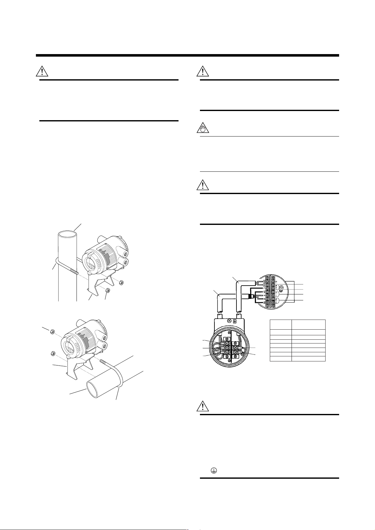
The external signal wirings are connected into the
terminal inside the converter. Please connect to each
terminal (Please refer to Figure 3.2.1) by taking off a
cover backside the converter.
Excitation Cable
Dedicated Cable
AM011-4
Converter SE14
Power supply
Protective ground
4 to 20 mA DC output
Pulse or alarm output
Horizontal pipe Mounting
Nut
Bracket
2-inch pipe
U-Bolt
Figure 3.1.1 Magnetic Flow Converter Installation
F030101.EPS
3.2 Wiring Precautions
This section is described wiring only for converter
side. Please see "Wiring" in SE***DJ/EJ Magnetic
Flow Tube User's Manual for flow tube side.
A
B
C
Figure 3.2.1 Wiring
Flow Tube
EX2
EX1
Converter
Terminals
SA
A
B
SB
C
Ex1
Ex2
NOTE : Terminate those shielding wire
terminals using tape.
Flow Tube
SE***DJ/EJ
(See NOTE below)
(See NOTE below)
3.2.1 Protective Grounding
CAUTION
Please be sure to connect protective grounding
of ADMAG SE with cable of 2mm2 or larger
cross section in order to avoid the electrical
shock to the operators and maintenance engineers and prevent the influence of external
noise. And further connect the grounding wire to
the mark (100Ω or less).
3-1
A
B
C
Ex1
Ex2
IM 1E10C1-E
F030201.EPS
3. INSTALLATION
3.2.2 General Precautions
Please give attention to the followings in wiring.
CAUTION
• Please pay attention to avoid the cable is
bended excessively.
• Please do not connect cables outdoors in case
of rain to prevent damages from dew formation
and to keep insulation inside the terminal box
of the flowmeter.
• The all cable ends are to be provided with
round crimp-on terminal.
• The power cables and output signal cables
must be routed in separate steel conduit tubes
or flexible tubes.(except 4-core 24VDC cable
wiring.)
• When waterproof glands or union equipped
waterproof glands are used, the glands must be
properly tightened to keep the box watertight.
•Please install a external switch or circuit
breaker as a means of power off (capacitance;
15A, conform to IEC947-1 and IEC947-3). The
preferable location is either near the instrument
or other places to easy operation. Furthermore, please indicate "power off equipment" on
the those external switch or circuit breaker.
• Please be sure to fully tighten the terminal box
cover before the power is turned on. After
tightening the covers, please be sure to fix it
with the special screw using a hexagonal
wrench attached.
• Please be sure to turn off the power before
opening the terminal box cover.
• In case of DC power supply, a plug is attached.
When 4-core cable is used, please put that
plug into unused electrical connection port.
3.2.3 Cable Types
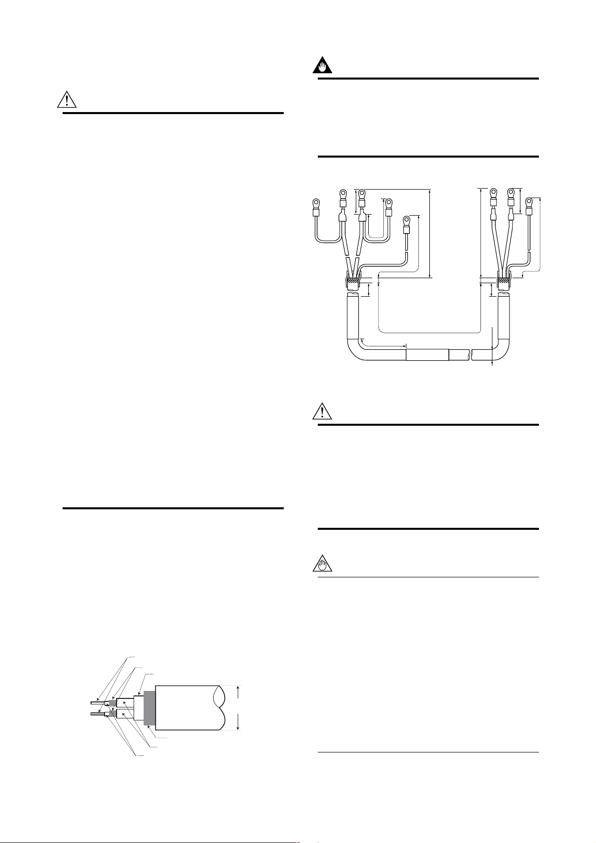
IMPORTANT
If the cable is longer than required, cut off any
extra length, rather coiling it up, and terminate
the conductors as shown in Figure 3.2.3. Avoid
using intermediate terminal boards to extend the
cable length, or this will interrupt the shielding.
Unit : mm (inch)
ACB
SA
(WHITE)
On the
converter side
Figure 3.2.3 Treatment of Dedicated Signal Cable
25 (0.98)
(BLACK)
150
8 (0.3) Max.
(5.9)
20 (0.8)
SB
50 (1.97)
(RED)
L (SPECIFIED LENGTH)
70 (2.76)
80 (3.15)
AM011*A
ACB
90 (3.5)
(WHITE)
8 (0.3) Max.
150
(5.9)
ø10.5 (0.4)
(BLACK)
On the flow
tube side
F030203.EPS
CAUTION
Since A, B, SA, SB, and C all operate at different electrical potentials, securely insulate them
from each other so they do not touch.
The shields must not be allowed to touch each
other or to touch the case.
Cover each shield with vinyl tube or wrap in vinyl
tape.
55 (2.2)
90 (3.5)
(RED)
(1) Dedicated Signal Cable(AM011)
The flow signal is transmitted via this dedicated cable.
The cable is constructed with double shielding over the
two conductors, and used heat-resistant vinyl as the
outer jacket material.
Finished diameter: 10.5 mm (0.413 in.)
Maximum length: 30 m (98 ft)
Maximum temperature: 80°C (176°F)
Conductors
Shields
Tape
Outer jacket
Shield
Insulation
Insulation
Figure 3.2.2 Dedicated Signal Cable AM011
10.5mm
(0.413in.)
F030202.EPS
NOTE
Conductors A and B carry the signal from the
electrodes, and C is at the potentials of the liquid
it self (signal common) . Shields SA and SB are
kept at the same potentials as the individual
electrodes (these are actively driven shields).
This is done to reduce the effect of the distributed capacitance of the cable at long cable
length. Note that, since the signals from the
individual electrodes are impedance converted
inside the converter, errors will result if they
come in contact with any other component.
Great care must be taken in the cable end
treatment.
3-2
IM 1E10C1-E
3. INSTALLATION
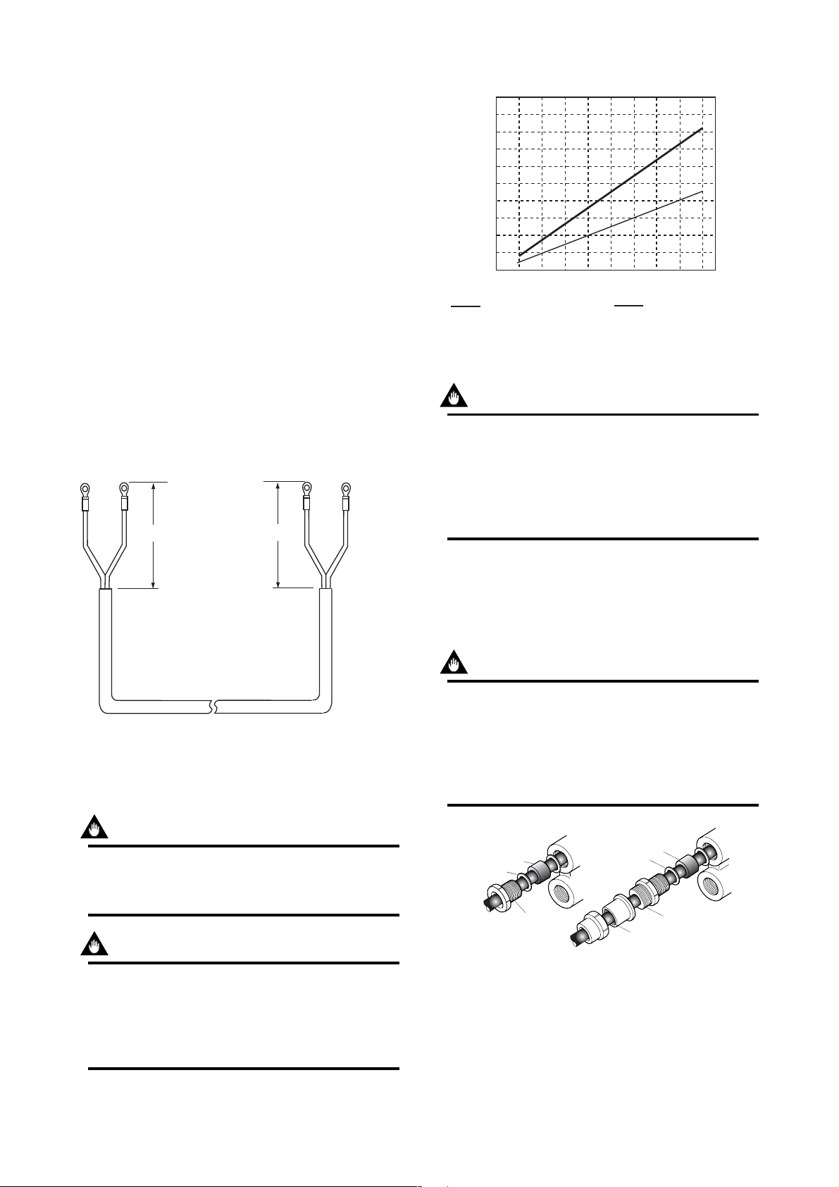
(2) Power, Excitation, or Output Cable
Power Cable
• Crimp-on Terminal
• Green/Yellow covered conductors shall be used only
for connection to PROTECTIVE CONDUCTOR
TERMINALS.
• Conform to IEC277 or IEC245 or equivalent
national authorization.
Excitation or Output Cable
• Please use Polyvinyl chloride insulated and sheathed
control cables (JIS C3401) or Polyvinyl chloride
insulated and sheathed portable power cables (JIS
C3312) or equivalents.
Outer Diameter
•6.5 to 12mm in diameter (10.5 to 11.5 mm for
waterproof gland / ECG, /ECU)
Nominal Cross Section
• Single wire; 0.5 to 2.5mm2 , Stranded wire; 0.5 to
2
2.5mm
EX1
EX2
60
(2.4)
85
(3.3)
Unit: mm (inch)
EX1
EX2
1000
(3300)
900
(2970)
800
(2640)
700
(2310)
Allowed
600
cable
(1980)
length
500
m(ft)
(1650)
400
(1320)
300
(990)
200
(660)
100
(330)
0
Cable cross section area : 1.25mm
Supply Voltage and Cable Length
20
22
24
Usable range E(V)
2
26
28
Cable cross section area : 2mm
F030205.EPS
Figure 3.2.5 Supplied Power and Cable Length
(2)Setting Power Supply Frequency
IMPORTANT
In case of DC power supply, the frequency of
the power supply has to be adjusted. Please
adjust for the local power frequency. The power
supply frequency is set in parameter B12 (or
Power freq for HART). Refer to 5.4, 6.5.4, or
7.3.4 for data setting procedure.
2
On the converter side On the flow tube side
F030204.EPS
Figure 3.2.4 End Treatment of Excitation Cable
3.2.4 DC Connections
(1)Connecting Power Supply
IMPORTANT
In case of 24VDC power supply, AC power
supplies or reversed polarities cannot be connected. It will cause the fuse to burn out.
IMPORTANT
In case of 24VDC power supply, the specification for the supply voltage is 24VDC (-15 to
+20%), but the input voltage of the converter
drops due to cable resistance so it should be
used within the following range.
3.2.5 Wiring Ports
Please select the most suitable standard of wiring
procedure for the wiring ports by customer’s own.
(1)Using the Waterproof Gland
IMPORTANT
To prevent water or condensate from entering
the converter housing, waterproof glands are
recommended. Do not over-tighten the glands or
damage to the cables may result. Tightness of
the gland can be checked by confirming that the
cable is held firmly in place.
Gasket
Gasket
Washer
Tightening gland
Water-proof gland(/ECG)
Figure 3.2.6 Waterproof Gland
(2)Conduit Wiring
In case of conduit wiring, please use the waterproof
gland to prevent water flowing through the conduit
pipe into the wiring connection.
Washer
Tightening gland
G1/2
Water-proof gland with union joint(/ECU)
F030206.EPS
3-3
IM 1E10C1-E
3. INSTALLATION
Please slope the conduit pipe down, and install a drain
valve at the low end of the vertical pipe.
Please open the drain valve regularly.
Drain valve
F030207.EPS
Figure 3.2.7 Conduit Wiring
3.2.6 Connecting to External Instru-
ments
CAUTION
All the devices to be connected to current
output and pulse output must be conformed to
CSA1010, CSA950, or IEC950.
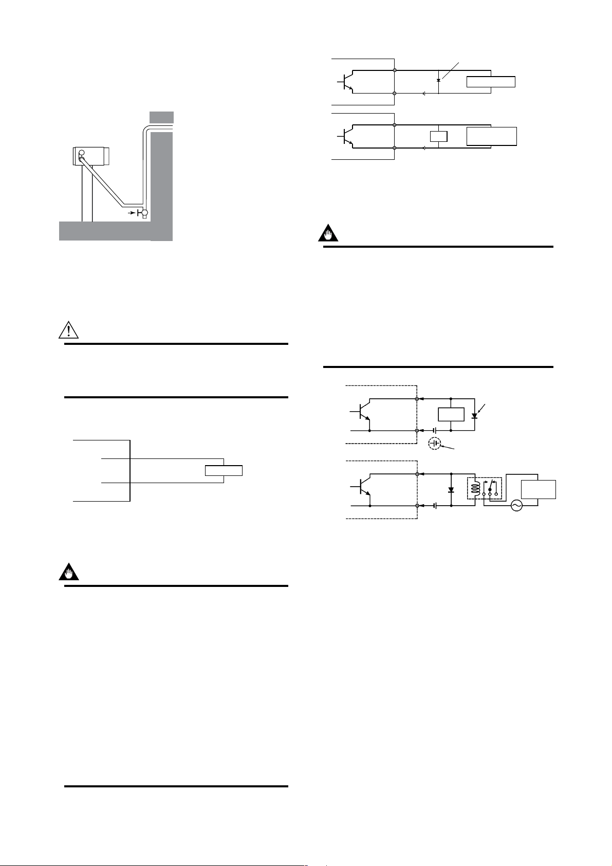
(1)Analog Signal Output(4 to 20mADC)
ADMAG SE
ADMAG SE
PULSE OUT
PULSE OUT
PLS/ALM+
+
–
PLS/ALM–
PLS/ALM+
+
–
PLS/ALM–
Protective diode
Mechanical counter
30 V DC, 0.2A. max*
*In case of FM Nonincendive type, 0.135A max.
Load
Universal counter or
Electronic counter
F030209.EPS
Figure 3.2.9 Pulse Output Connection
(3)Alarm or Status Output
IMPORTANT
This is a transistor contact(insulated type) so
attention must be paid to voltage and polarity
when making connections.
This output can not switch an AC load. To do
this, another relay (see the figure below) is
required.
* The alarm output works from "close"(Normal) to
"open"(Alarm).
ADMAG SE
PLS/ALM+
Protective diode
Load
PLS/ALM–
+
ADMAG SE
CUR+
–
CUR–
+
RECEIVER
–
Load Resistance
max. 600 Ω
F030208.EPS
Figure 3.2.8 Connection for Analog Singal Output
(2)Pulse Output
IMPORTANT
Please give attention to voltage and polarity in
wiring, because it is transister contact (insulation type.)
• In case of the filtering constant of Electric
Counter is more than the pulse width, it makes
signal decreases and can not be calculated
correctly.
• In case of input impedance of electric counter
is large inductive noise from power supply
bring bad influence to measurement. To
calculate correctly, it is recommended to use
shield cable or to make input impedance small
enough within the limits of pulse output of
flowmeter.
This connection cannot be made.
ADMAG SE
PLS/ALM+
PLS/ALM–
External
Power supply
30 V DC, 0.2A. max*
*In case of FM Nonincendive type, 0.135A max.
Figure 3.2.10 Contact Output Connection
Magnetic
valve
AC power supply
F030210.EPS
3-4
IM 1E10C1-E
4. BASIC OPERATING PROCEDURES
4. BASIC OPERATING PROCEDURES
All data settings can be performed with the three keys on the front panel (SET,SHIFT,
and INC), or using a handheld Brain Terminal (BT) or using a HART communicator.
The following sections describe basic data components and how to use the three panel
keys. (Please refer to Chapter 6 for the operation via Brain Terminal and Chapter 7 for
the operation via HART communicator.)
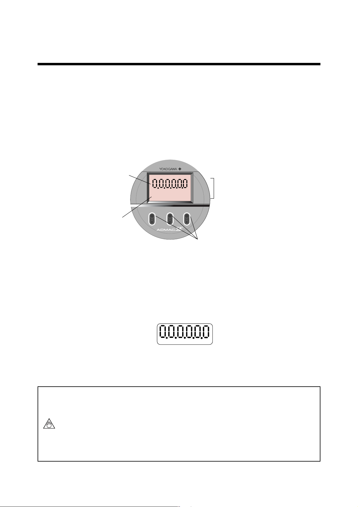
4.1 Liquid Crystal Display (LCD)
ADMAG SE display panel (if equipped) shows the components as follows.
4:Decimal Point
1:Data Display
3:Unit Display
µMmNkgalbbl
scftm3 /d /s /h /m
SET
SHIFT
%
INC
2:Infrared Switches (if equipped)
Figure 4.1 Components of Display
1: Data Display: Displays flow rate data, setting data and type of alarm generated.
2: Infrared Switches: These keys are used to change the display and type of setting data.
3: Unit Display: Displays flow rate units. In order to display other units, the
required unit label should be selected from the provided data
sheets.
4: Decimal Point: Displays decimal point.
• Structure of the Display
* The Display consists of six figure and five dots for the decimal point between them.
* Two types of data can be entered : direct entry of numerals and entry of desired data
items using codes.
Please refer to Chapter 11. Parameter List for information on how to change settings.
NOTE
The infrared switches operates as “ON” status by detecting the infrared ray reflection
from a finger put over the switches through the glass plate of the cover. Switches are
just below the printed letters SET, SHIFT, or INC on the faceplate and are circled
with a white line.
When you “touch” the swiches, please note the follwing.
The switches may operate even when you don’t touch the glass plate if your finger
comes near just above the glass plate. so please touch the switches sliding in your
finger from the lower part of the glass plate. Also be sure not to touch more than
one switch at one time by covering your other fingers over the faceplate.
4-1
IM 1E10C1-E
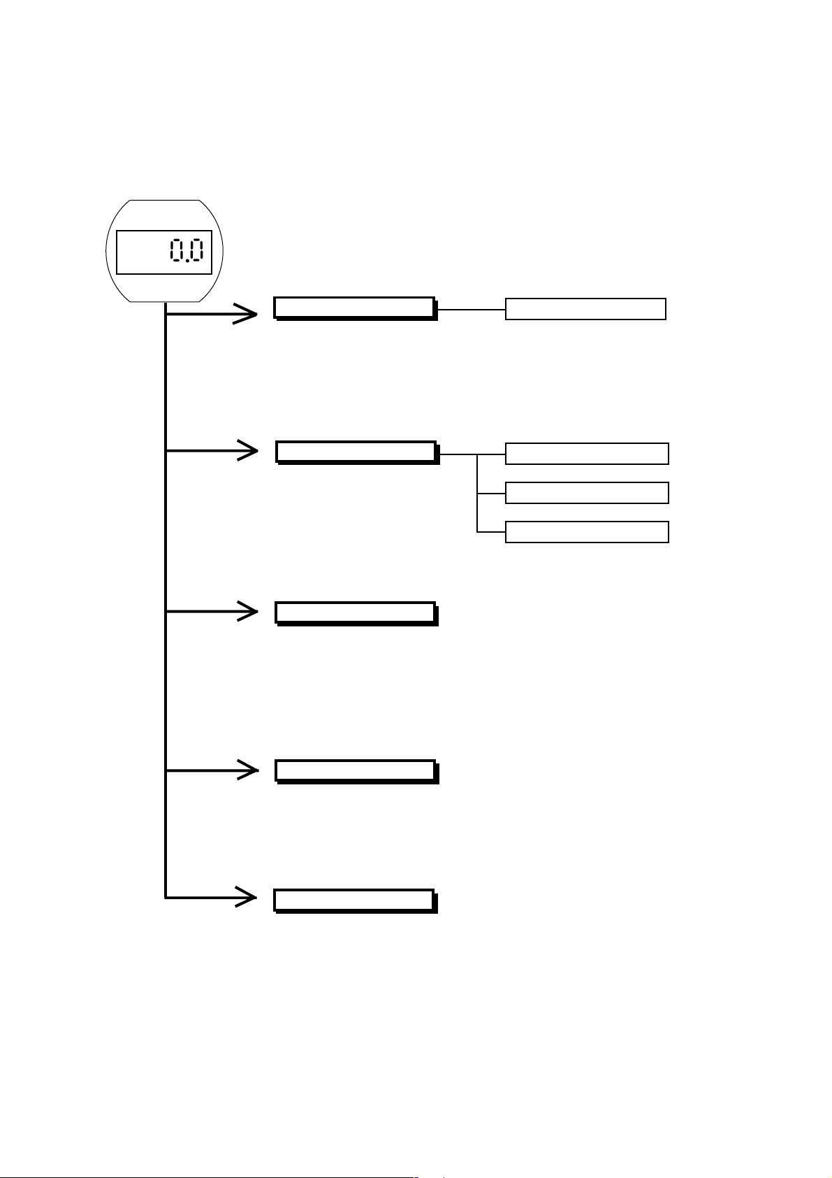
4.2 Types of Display Data
The Display Data is divided into 5 types as follows.
4. BASIC OPERATING PROCEDURES
Please refer to section 4.2.2
Flow Rate Display Mode
This mode indicates the instantaneous flow rate and totalization data.
Display settings can be set in the Setting Mode and parameter
No.“d01” (DISP SELECT) by using infrared switches, Brain Terminal,
or HART communicator.
Setting Mode
This mode makes certain about
contents of parameter and
rewrite data.This mode is called
up from Flow Rate Display Mode
by touching the SET key for 3
sec. and inputting a password.
Alarm Display Mode
When an alarm occurs in the
Flow Rate Display Mode, this
mode indicates the alarm code
number and normal data
alternately.
Please refer to section 4.2.4
Pass-Word Input Mode
Please refer to section 4.2.3
Number Changing Mode
Data Changing Mode
Data confirmation Mode
Auto Zero Mode
This mode is indicated during
automatic zero setting.
Indicator Error Mode
This mode is shown in case the
keys keep staying “ON” by stains
or obstacles on front glass of the
case.The error is canceled by
cleaning them.
4-2
Please refer to section 4.2.5
Please refer to section 4.2.6
IM 1E10C1-E
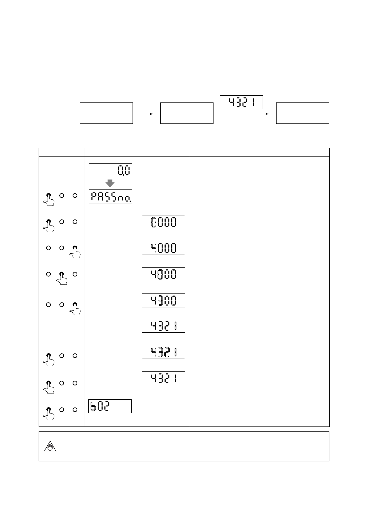
4.2.1 The Initial Procedure to Change the Display Mode
•The procedure of changing the display from the Flow Rate Display Mode into the
Setting Mode by using infrared switches on the converter is described as follows.
(1) Procedure in General
4. BASIC OPERATING PROCEDURES
The Flow Rate
Display Mode
SET key
(for 3 sec.)
The Pass-word
Input Mode
Password Input
(It is always “4321”.)
(2) Procedure in Detail
Switch Operation Display Description
(After power on)
SET SHIFT INC
(for 3 sec.)
SET SHIFT INC
SET SHIFT INC
SET SHIFT INC
(example)
To go to the Setting Mode, it is needed to go to the Password
Input Mode first. Please touch the SET key for 3 sec., and the
display goes into the Password Input Mode.
By touching the SET key again, the display goes into the
Number Input Mode. Please input the Password as follows, by
touching the SHIFT and INC keys.
By touching the INC key for some moment, change “0” into
“4”.
By touching the SHIFT key, the cursor moves to the next digit.
The Setting
Mode
SET SHIFT INC
SET SHIFT INC
SET SHIFT INC
SET SHIFT INC
NOTE
By touching the INC key for some moment again, change “0”
into “3”.
By continuing this for the rest of two digits, please change the
whole digits into “4321”.
By touching the SET key, whole Display is blinking.
And by touching the SET key again, setting the password is
completed.
(Setting is now completed)
By touching the SET key again, the display goes to the number
changing mode.
In the Password Input Mode, if keys were not operated for more than 20 sec., or if
correct password were not set, the display goes back into the Flow Rate Display Mode
automatically.
4-3
IM 1E10C1-E
4. BASIC OPERATING PROCEDURES
• The procedure of returning from the Setting Mode to the Flow Rate Display
Mode by using infrared switch on the converter is described as follows.
Switch Operation Display Description
The number changing mode of the Setting Mode.
SET SHIFT INC
(SHIFT key first)
(1) Functions of
Number
Changing Mode
SET SHIFT INC
(2) Functions of
Number
Changing Mode
(example)
After all settings have been completed, touch the SET key
simultaneously while touching the SHIFT key. Then the display
goes back to the Flow Rate Display Mode.
• Additional information on the functions of the keys is described here.
SHIFT
key
When the SHIFT key is touched in the Number Changing Mode, it shows as follows.
<< The Cursor Position moves alternately by touching the
SHIFT key.
Cursor Position
Cursor Position
key
INC
The INC key in the Number Changing Mode has each working at each cursor position.
a) In case the Cursor Position is at upper figure
SET SHIFT INC
The parameter number changes the followings by touching the INC key.
b) In case the Cursor Position is at lower figure
The parameter number changes from small number to big one by touching the INC key.
For example; 02, 03,
...
, 37, 02, 03,
...
(in case of parameters with “b”)
4-4
IM 1E10C1-E

4.2.2 Flow Rate Display Mode
• Flow Rate Display Mode indicates flow rates and totalization data. ADMAG SE can
indicate 12 types as follows.
INDICATOR
DISPLAY ITEM CONTENTS BT200 SETTING
Flow Rate (%)
Flow Rate
Actual Flow Rate
Instantaneous flow rate is displayed
within a range of -8 (or -108%) to
108% for the span.
The actual meter rate of instataneous
flow rate is displayed. (See NOTE)
The decimal place is the same as for
the span setting. However, since a
decimal point set at the least
significant bit cannot be displayed.
Parameter
No.
d01
d01
Code
No.
D01: DISP SELECT
00
D01: DISP SELECT
01
4. BASIC OPERATING PROCEDURES
HART
Communicator
RATE(%)
RATE
Disp Select
PV % rnge
Disp Select
PV
Actual Flow Rate
Totalization Values
Reverse Flow Rate
Totalization Values
Differential Between the
Forward and Reverse Flow
Totalization Values
Alternate Display of Flow Rate
(%) and Forward Flow Rate
Totalization Values
Alternate Display of Actual
Flow Rate and Forward Flow
Rate Totalization Values
Alternate Display of Actual
Flow Rate and Forward Flow
Rate(%)
Alternate Display of Flow Rate
(%) and Reverse Flow
Totalization Values
Alternate Display of Forward
Flow Rate and Reverse Flow
Totalization Values
Alternate Display of Flow Rate
(%) and Differential Flow
Totalization Values
Alternate Display of Forward
Flow Rate and Differential
Flow Totalization Values
Display actual flow rate totalization
value
Display reverse flow rate totalization
value
Differential totalization between
forward totalization and reverse
totalization is displayed.
Display alternately between display
of “RATE(%)” and “FOR. TTL”
every 4 second interval.
Display alternately between display
of “RATE” and “FOR. TTL”.
Display alternately between display
of “RATE” and “RATE(%)” every 4
second interval.
Display alternately between display
of “RATE(%)” and “REV. TTL”
every 4 second interval.
Display alternately between display
of “RATE” and “REV. TTL” every 4
second interval.
Actual flow rate (%) and differential
between forward and reverse
totalization values are indicated
alternately every 4 sec.
Actual flow rate and forward and
reverse totalization values are
indicated alternately every 4 sec.
d01
d01
d01
d01
d01
d01
d01
d01
d01
d01
D01: DISP SELECT
02
D01: DISP SELECT
03
D01: DISP SELECT
04
D01: DISP SELECT
05
D01: DISP SELECT
06
D01: DISP SELECT
07
D01: DISP SELECT
08
D01: DISP SELECT
09
D01: DISP SELECT
10
D01: DISP SELECT
11
FOR. TOT AL
REV. TOTAL
DIF. T OTAL
RATE %/FOR TTL
RATE/FOR TTL
RATE/RATE %
RATE %/REV. TTL
RATE/REV . TTL
RATE %/DIF. TTL
RATE/DIF. TTL
Disp Select
Totl
Disp Select
Rev. totl
Disp Select
Diff. totl
Disp Select
PV % rnge/Totl
Disp Select
PV/Totl
Disp Select
PV % rnge/PV
Disp Select
PV % rnge/Rev. totl
Disp Select
PV/Rev. totl
Disp Select
PV % rnge/Diff. totl
Disp Select
PV/Diff. totl
NOTE
• The display can set the units by setting parameter No.“b04” and “b05”.
• When special display of flow rate is specified in parameter “D10 flow user unit”, this
special display has higher priority in displaying than actual flow rate.
•Those 12 types function can be selected and set by changing into the Setting Mode.
(Please refer to 4.2.3 Setting Mode.)
• Those 12 types function can be selected by using infrared switches, Brain Terminal,
or HART communicator. (For using BT, please refer to Chapter 6. OPERATION VIA
BRAIN TERMINAL(BT 200). For using HART communicator, Chapter 7. OPERATION VIA HART Communicator.)
4-5
IM 1E10C1-E
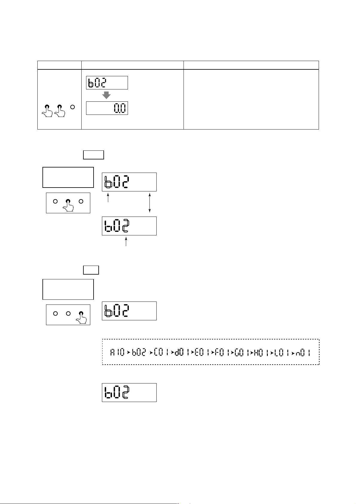
4.2.3 Setting Mode
The Setting Mode confirms contents of parameter and rewrite data.
Number
Changing Mode
Cursor position is blinking.
4. BASIC OPERATING PROCEDURES
• Detailed procedures of data setting are explained in “ Chapter 5. Function and Data
Settings”.
• Procedure of data setting
* When the display is in the Setting Mode just after power
ON, it always starts from “b02”.
* After that, it starts from the former selected number.
SET SHIFT INC SET SHIFT INC
*Keys for number changing
SHIFT: for changing positions (to the right)
INC: for changing alphabets or numerals
SET SHIFT INC
Data Changing
Mode
*By touching the SET key the display goes to the Data Changing Mode.
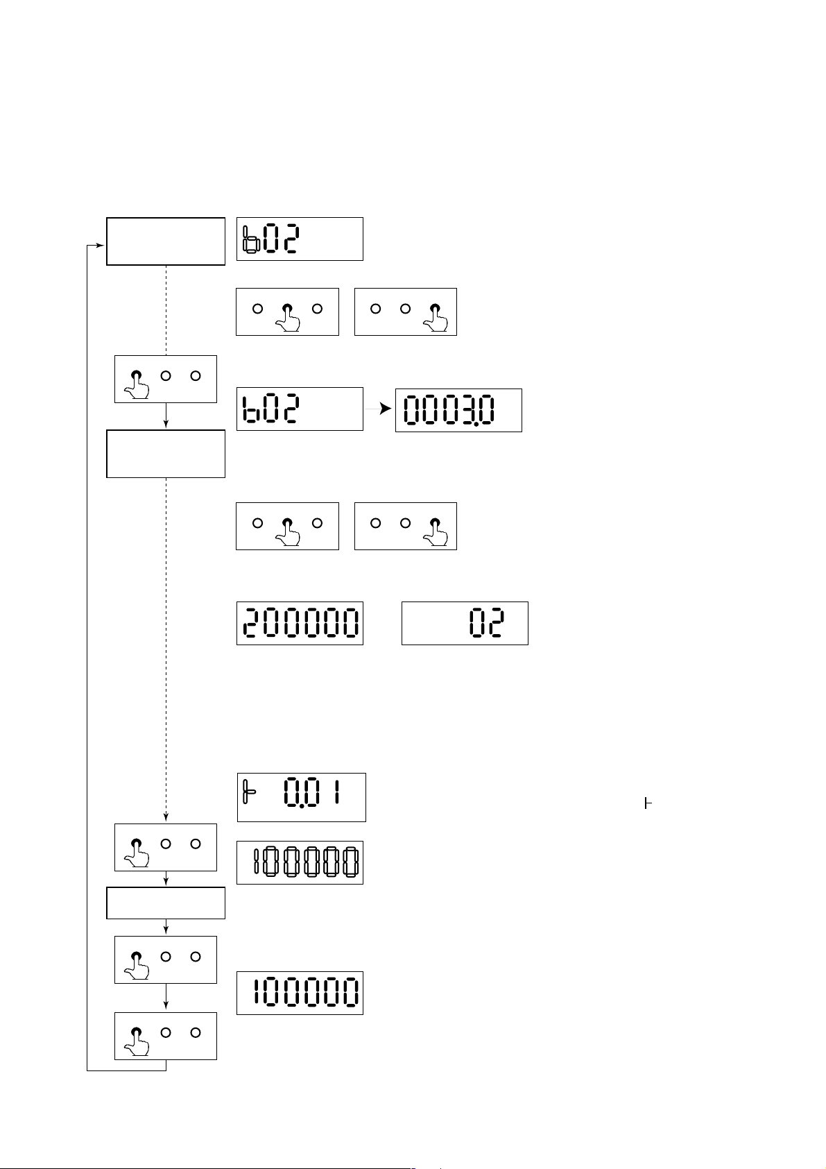
* Two types of data can be entered : direct entry of numerals and entry of desired data
items using codes. Please refer to “Chapter 11. Parameter List” for information on
how to change settings.
SET SHIFT INC SET SHIFT INC
* Keys for data changing
SHIFT: for changing positions (to the right)
INC: for changing numerals or the position of
decimal point
*Data types are as follows.
Direct entry of numerals Entry of selected number
5-figure data = A decimal point is sure to show somewhere, The last figure (6th figure)
is always SPACE.
6-figure data(totalized value) = A decimal point doesn't show anywhere and no SPACE.
Selection type data = It is always 2-figure(other figures are always SPACE).
SET SHIFT INC
Data Confirmation Mode
SET SHIFT INC
SET SHIFT INC
Whole display is blingking.
Data is completed.
The marks are always shown at the highest figure.
It changes: “+” and “–” (“+” is shown as “ ”.)
*When it is the Data Changing Mode and touch SET key, it
changes into the Check Up Mode, whole of the display
begins to blink.
* During the display is blinking, touch the SET key, then the
data is completed.
* Then touch the SET key again and the display goes back to
the Number Changing Mode.
* During the display is blinking and touch other keys except
the SET key, the data setting is canceled and the display
goes back to the Number Changing Mode.
4-6
IM 1E10C1-E
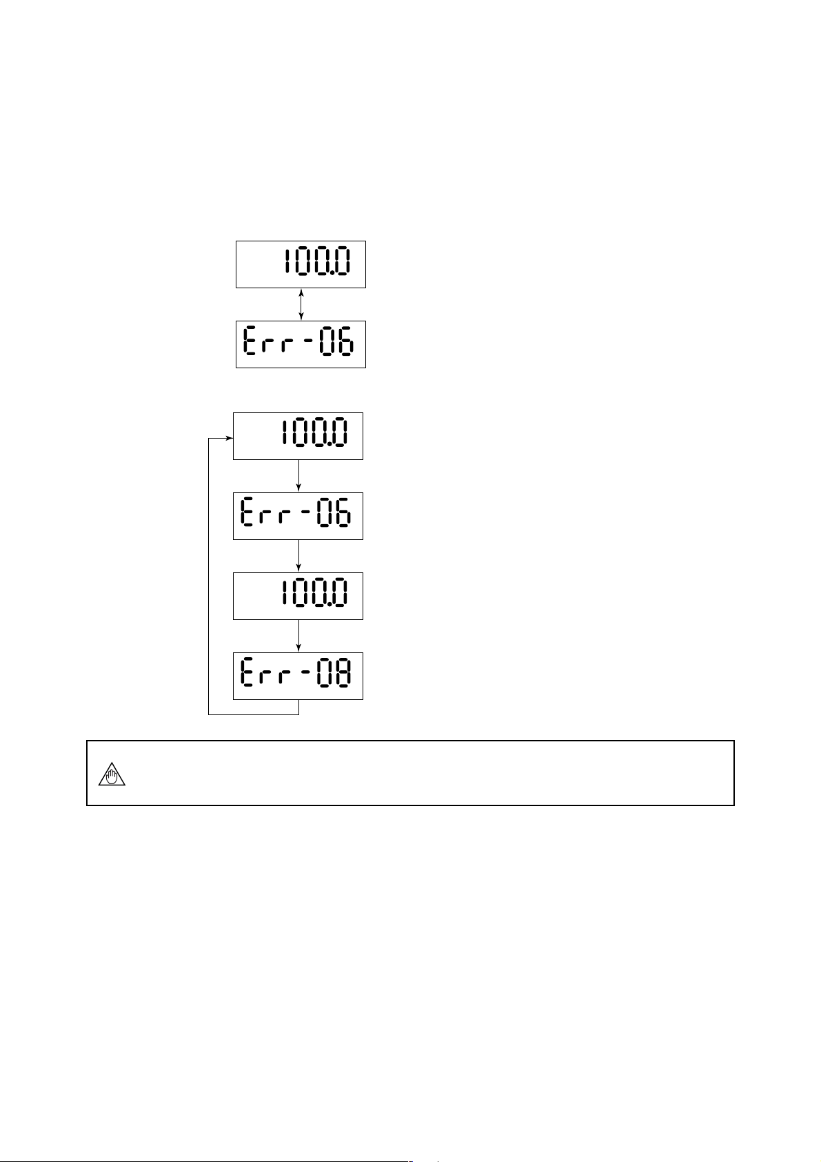
4.2.4 Alarm Display Mode
• When an alarm occurs, a content of the alarm is shown as an alarm code number.
However, this mode is available during the Flow Rate Display Mode.
In this mode, alarm number and flow rate are shown alternately.
For example;
• When alarm No. 6 is raised.
• When alarm No.6 and No.8 are raised at the same time.
4. BASIC OPERATING PROCEDURES
<< Flow Rate is indicated for 4 sec.
%
<< Alarm No. is indicated for 2 sec.
<< Flow Rate is indicated for 4 sec.
%
NOTE
<< Alarm No.6 is indicated for 2 sec.
<< Flow Rate is indicated for 4 sec.
%
<< Alarm No.8 is indicated for 2 sec.
For further description of the alarm functions, please refer to “Chapter 8.2 Selfdiagnostics Functions”.
4-7
IM 1E10C1-E
4.2.5 Auto Zero Mode
•Three ways of the auto zero adjustment can be done by using the infrared switches on
the converter, BT Terminal, or HART communicator.
Please refer to “8.1 Pre-Operation Zero Adjustment” in detail.
• The display can be changed into the Auto Zero Mode from any mode.
• The Auto Zero Mode is shown as follows (for 20sec.).
• When the Auto Zero Mode is finished, the display goes back into the Flow Rate
Display Mode automatically.
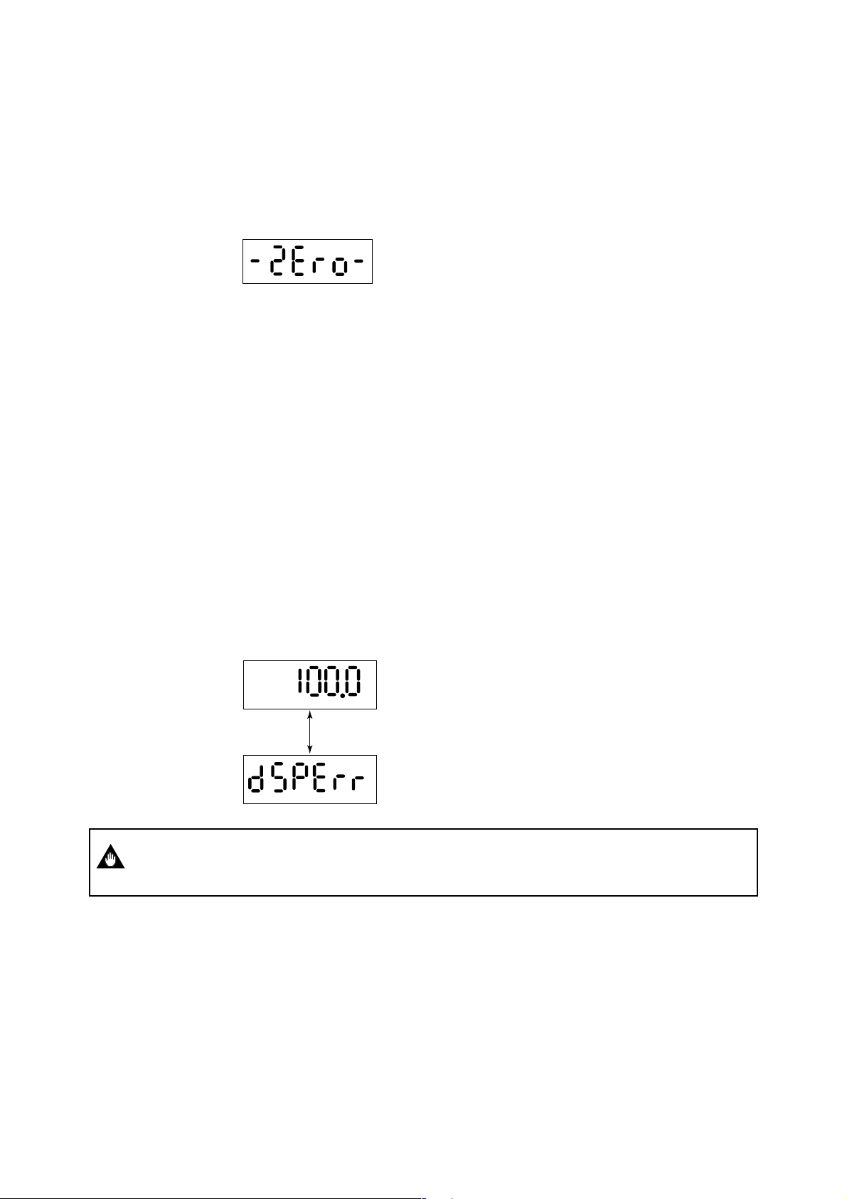
4.2.6 Indicator Error Mode
In the event the glass is stained or objects are placed near or on the glass, the switches
can be activated due to the infrared deflection. This will cause the "Password Input
Mode" to be displayed frequently and make the normal display mode unavailable. The
following comments relate to this possible occurrence.
*When the front glass of case is stained, please wipe out the glass by soft and dry
cloth.
*In case that each key keeps touching for more 120 sec. and it is continued, the
Password Input Mode is not available to enter.
*In case all keys are “OFF” for more 3 sec. , this mode is cancelled.
*This condition (the above-mentioned) is not an alarm, but the followings are shown
on LCD to indicate this condition.
(4 to 20 mA Output , Status Output , Flow Rate Indication Value and Self-check
Function work normally.)
*When these errors are raised, the display indicates alternately as follows.
4. BASIC OPERATING PROCEDURES
IMPORTANT
<< Flow Rate is indicated for 4 sec.
%
<< Warning is indicated for 2 sec.
In case of the front cover is loosened, "dSPErr" may occur, so please make sure the
cover is always fastened tightly.
4-8
IM 1E10C1-E
5. FUNCTION AND DATA SETTINGS
5. FUNCTION AND DATA SETTINGS
A Magnetic flowmeter calculates volume flow rate from a minute voltage that corresponds to the flow velocity of a fluid an outputs as a 4 to 20mA signal.
The three parameters must be set to obtain a correct signal.
NOTE
NOTE
Nominal size, flow span and meter factor must be set.
This chapter explaines how to set flow span, other functions and data settings.
Please set data correctly.
• you cannot set the leftmost digit of display to numeric value
greater than "4". If the leftmost digit of the span must be "4" or
more, set the numeric value beginning from the digit second
from the left on the display (the fourth digit).
• If the leftmost digit of the display is set to "3", the digits to its
right can be set to "0" only, regardless of the decimal point
position.
Basic Key Operations
How to change the display into the setting mode?
How to move the cursor on the display during parameter setting?
How to change the display into the data changing mode?
How to move the cursor in the data changing mode?
How to change the data?
Finally, How to input the set data?
Key OperationItem
SET
SHIFT
SET
SHIFT
INC
SET (Twice)
5-1
IM 1E10C1-E
5. FUNCTION AND DATA SETTINGS
5.1 Setting Nominal Size
Switch Operation Display Description
(See 4.2.1 The initial
procedure to change the
display)
SET SHIFT INC
Change the display into the setting mode through the password
input mode. (Please refer to Chapter 4 “BASIC OPERATION
PROCEDURES.”)
SET SHIFT INC
SET SHIFT INC
SET SHIFT INC
SET SHIFT INC
SET SHIFT INC
SET SHIFT INC
SET SHIFT INC
SET SHIFT INC
SET SHIFT INC
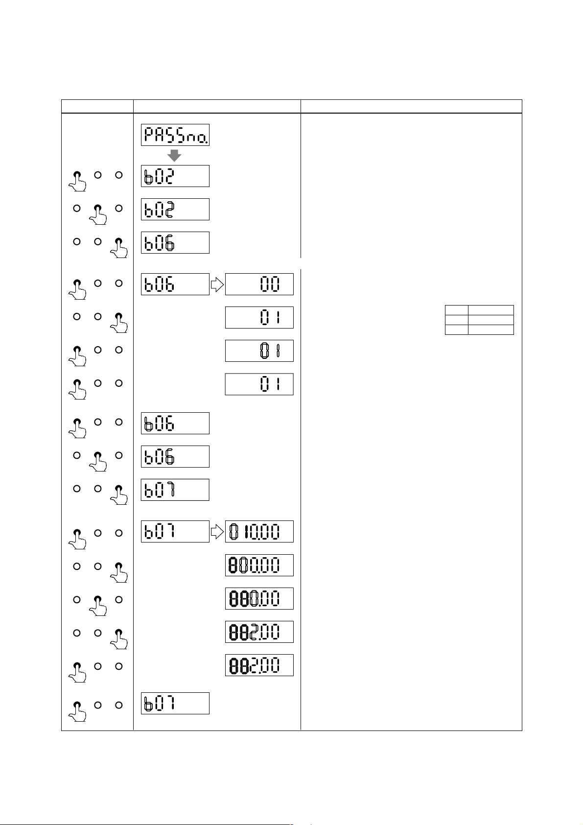
By touching the SHIFT and INC key, select the parameter No.
“b06”.
Defalt is set as 00 (Size Unit is mm). Below is an example to set it “01” .(Size Unit is inch)
By touching the SET key, change the display into the data
changing mode.
By touching the INC key, select code
“01” for inch.
By touching the SET key, whole Display is blinking.
And by touching the SET key again, the data is completed.
(Setting is now completed)
By touching the SET key again, the display goes back to the
number changing mode.
By touching the SHIFT and INC key, select the parameter No.
“b07”.
Code
00
01
Size Unit
mm
inch
SET SHIFT INC
SET SHIFT INC
SET SHIFT INC
SET SHIFT INC
SET SHIFT INC
SET SHIFT INC
Below is an example to change to “2.0”.
(Setting is now completed)
By touching the SET key, change the display into the data
changing mode.
By touching the SHIFT key, the cursor moves to the next digit.
By touching the INC key, change “1” into “0”.
By touching the SHIFT key, the cursor moves to the next digit.
By touching the INC key, change “0” into “2”.
By touching the SET key twice, the setting is completed.
By touching the SET key again, the display goes back to the
number changing mode.
5-2
IM 1E10C1-E

5.2 Setting Flow Span
(1) Determing the Flow Span
The flow rate span is the instantaneous flow rate value at which the output current is to
be 20mA.
Please determine the span under considering the followings.
• Please set the maximum flow rate at the most variable flow rate line.
If the flow rate of the fluid exceeds the flow rate span value, the flow rate that
exceeds this value (20mA or more) is not output and the flowmeter will not display
the correct flow rate. (108% or more can't be output)
• In a line where the flow rate is comparatively stable, set a value that is 1.5 to 2.0
times larger than the normal flow rate.
• Please set a value that will correspond to a flow velocity of 0.3 to 10m/s.
Please comfirm the flow velocity by sizing data or parameter No. “b13”.
(Parameter No. “b13” indicates corresponding flow velocity to set span)
• The basic input value for display is flow span value. It is recommended that the
accuracy of the first digit is in a 0.05 to 0.1% in case inputting the flow rate span
value.
For example, 30m3/h should be set as 30.00m3/h.
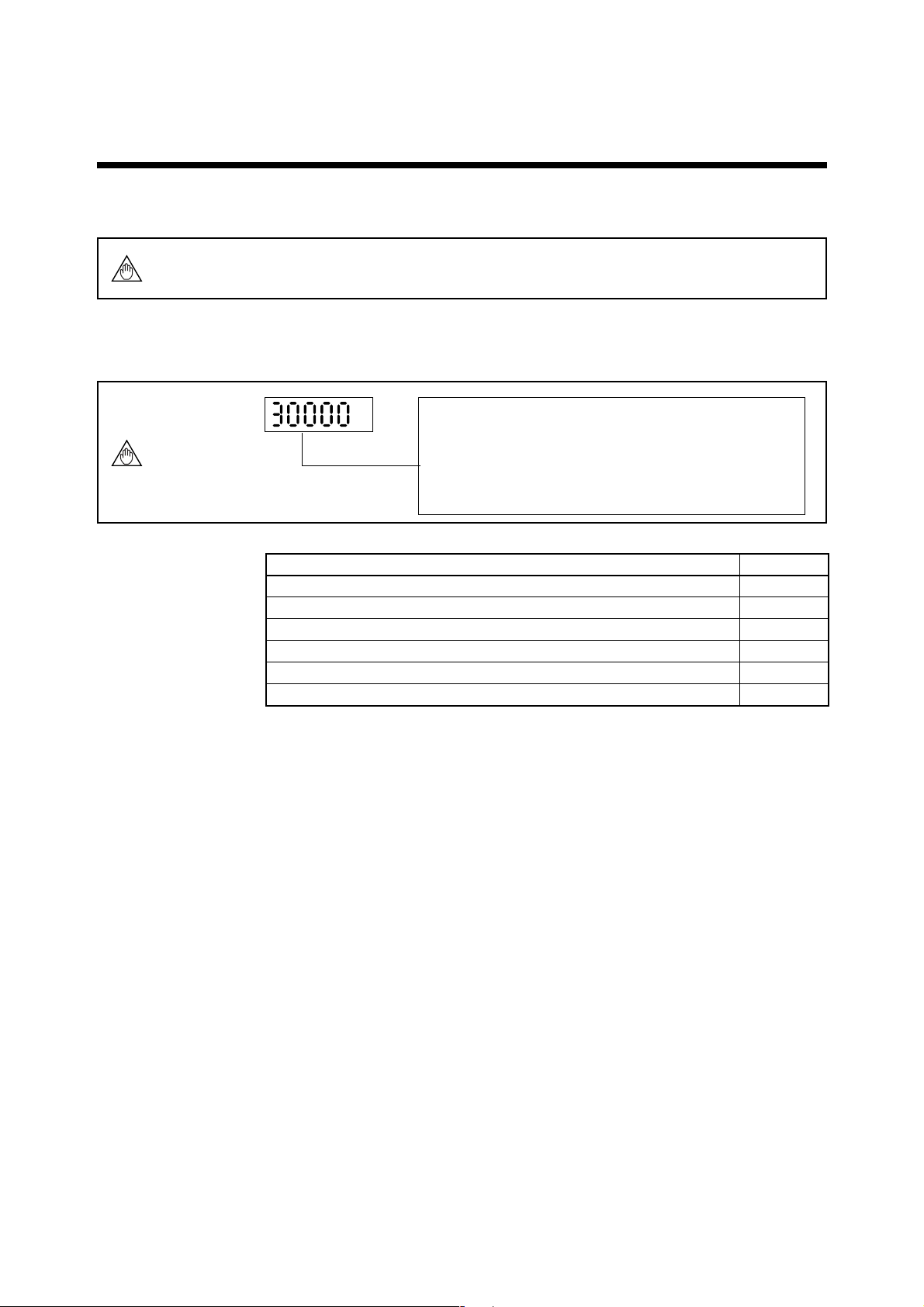
• In a span setting, the maximum value that can set is “30000” except any relation
with decimal position.
5. FUNCTION AND DATA SETTINGS
5-3
IM 1E10C1-E
5. FUNCTION AND DATA SETTINGS
(2) Span Settings by Infrared Switches on the Converter (Example: Flow Span 30.0m3/h)
Span Value Setting
Switch Operation Display Description
(See 4.2.1 The initial
procedure to change the
display)
SET SHIFT INC
Change the display into the setting mode through the password
input mode. (Please refer to Chapter 4 “BASIC OPERATION
PROCEDURES.”)
SET SHIFT INC
SET SHIFT INC
SET SHIFT INC
SET SHIFT INC
SET SHIFT INC
SET SHIFT INC
SET SHIFT INC
SET SHIFT INC
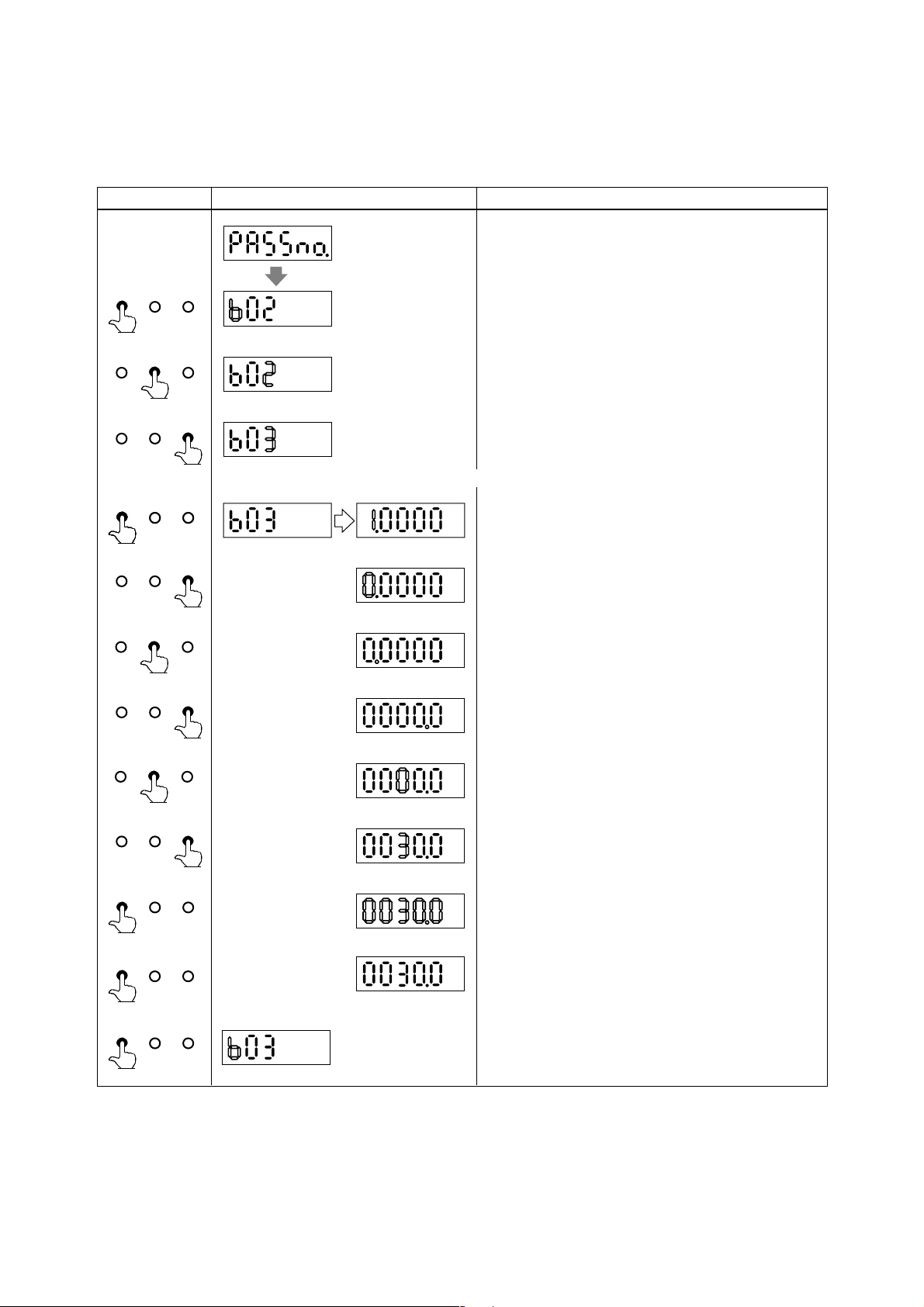
By touching the SHIFT and INC key, select the parameter No.
“b03”.
Defalt is set as 1.0000. Below is an example to change it into 0030.0.
By touching the SET key, change the display into the data
changing mode.
By touching the INC key, change “1” into “0”.
By touching the SHIFT key, the cursor moves to the decimal
point.
The decimal point on the cursor can be moved by touching the
INC key.
And by touching the SHIFT key, blinking part moves to the
right.
SET SHIFT INC
SET SHIFT INC
SET SHIFT INC
SET SHIFT INC
(Setting is now completed)
By touching the INC key, change “0” into “3”.
By touching the SET key, whole Display is blinking.
And by touching the SET key again, the data is completed.
By touching the SET key again, the display goes back to the
number changing mode.
5-4
IM 1E10C1-E
5. FUNCTION AND DATA SETTINGS
Setting Volume Measurement (m3) and Time Unit (/h)
Switch Operation Display Description
(Select m3)
SET SHIFT INC
SET SHIFT INC
SET SHIFT INC
Defalt : 12
SET SHIFT INC
SET SHIFT INC
SET SHIFT INC
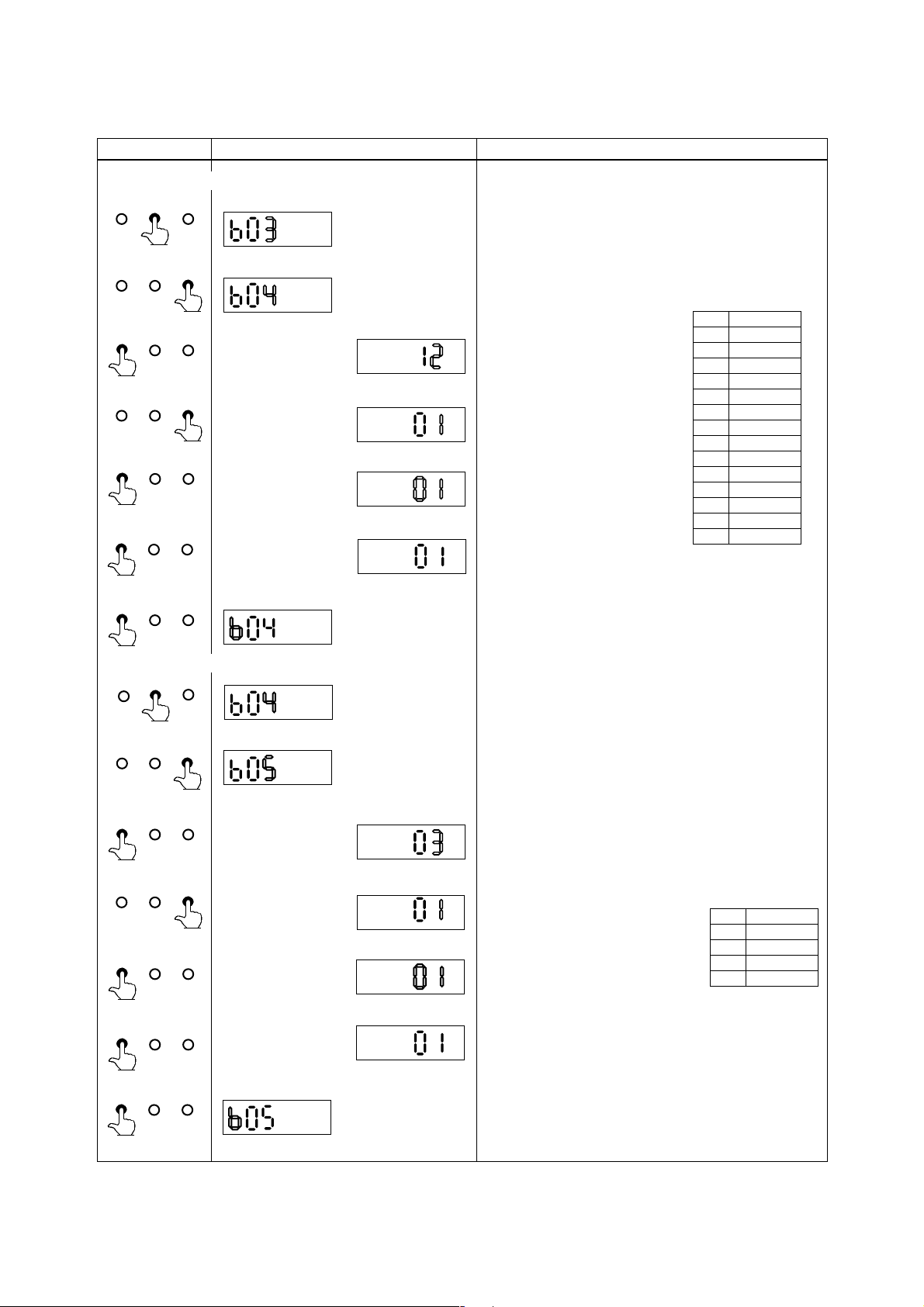
Change the display into the number changing mode through the
setting mode.
By touching the SHIFT and INC key, please select the
parameter No.“b04”.
And by touching the SET key,
change into the data changing mode.
By touching the INC key, set the “01”
(equivalent as m
3
)
By touching the SET key,
whole display is blinking.
And touching the SET key again,
the data is completed.
Code
00
01
02
03
04
05
06
07
08
09
10
11
12
13
Volume Unit
3
km
(103X
m3)
3
m
L(liter)
3
cm
(10-2X
m)
M gal
k gal
gal
m gal
k bbl
bbl
m bbl
u bbl
m
ft.
3
SET SHIFT INC
(Select /h)
SET SHIFT INC
SET SHIFT INC
SET SHIFT INC
SET SHIFT INC
SET SHIFT INC
SET SHIFT INC
Defalt : 03
And by touching the SET key, the data is completed and the
display goes back into the number changing mode.
By touching the SHIFT and INC key, select the parameter No.
“b05”.
By touching the SET key, change the display into the data
changing mode.
By touching the INC key, set the
Time Unit
“01” (equivalent as /h)
By touching the SET key,
whole display is blinking.
Code
00
01
02
03
/d
/h
/m
/s
And touoching the SET key again, the data is completed.
* If keys that except SET key are touched during display is
blinking, input data is not completed and back to former data.
SET SHIFT INC
(Setting is now completed)
By touching the SET key again, the display goes back to the
number changing mode.
5-5
IM 1E10C1-E
5. FUNCTION AND DATA SETTINGS
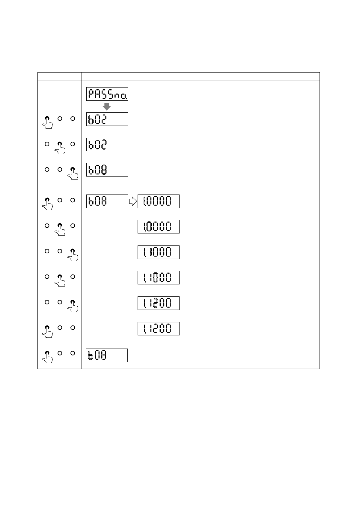
5.3 Setting Meter Factor
The meter factor is engraved on the data plate of the combined flow tube.
Switch Operation Display Description
(See 4.2.1 The initial
procedure to change the
display)
SET SHIFT INC
Change the display into the setting mode through the password
input mode. (Please refer to Chapter 4 “BASIC OPERATION
PROCEDURES.”)
SET SHIFT INC
SET SHIFT INC
SET SHIFT INCSET SHIFT INC
SET SHIFT INC
SET SHIFT INC
SET SHIFT INC
SET SHIFT INC
By touching the SHIFT and INC key, select the parameter No.
“b08”.
Defalt is set as 1.0000. Below is an example to set it “1.1200”.
By touching the SET key, change the display into the data
changing mode.
By touching the SHIFT key twice, the cursor moves to the next
digit.
By touching the INC key, change “0” into “1”.
By touching the SHIFT key, the cursor moves to the next digit.
By touching the INC key, change “0” into “2”.
SET SHIFT INC
SET SHIFT INC
(Setting is now completed)
By touching the SET key twice, the setting is completed.
By touching the SET key again, the display goes back to the
number changing mode.
5-6
IM 1E10C1-E
5. FUNCTION AND DATA SETTINGS
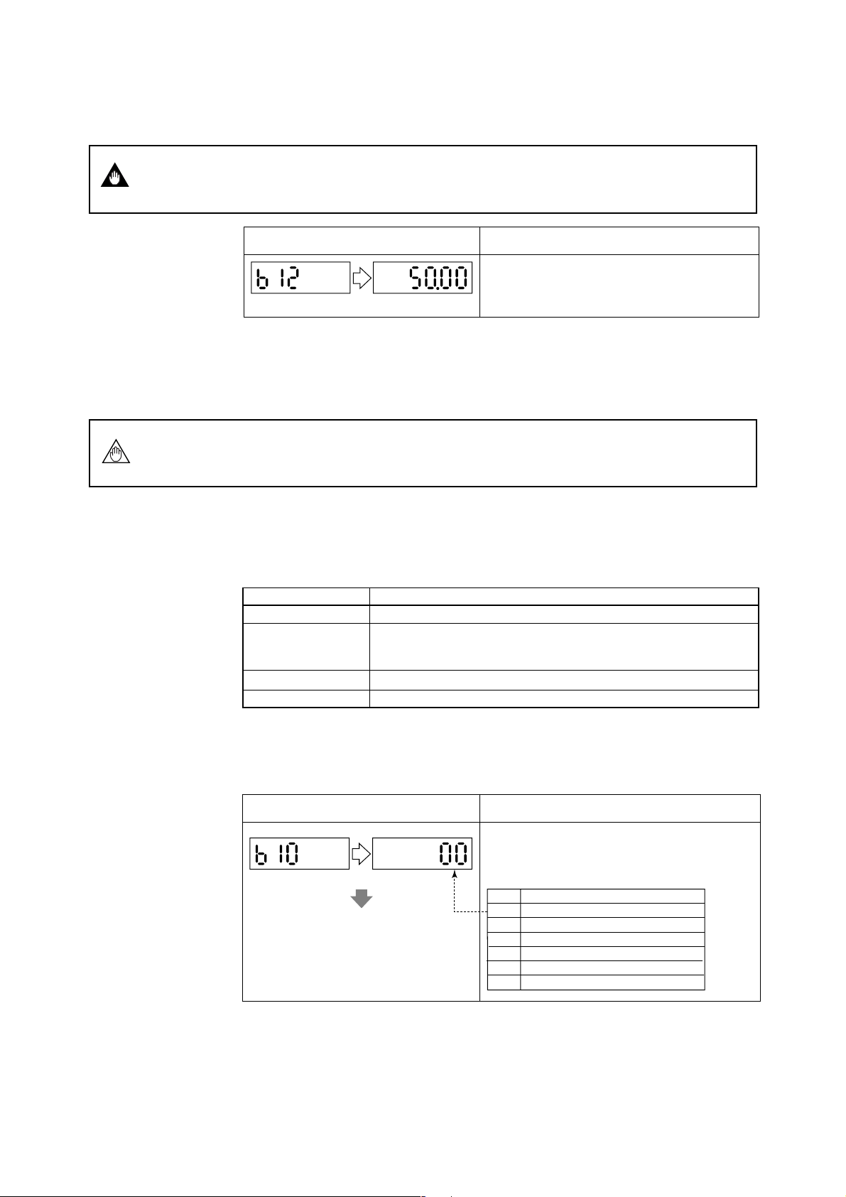
5.4 Power Frequency (For DC version only)
IMPORTANT
the frequency differs. The meter is set to 50.00Hz at the factory.
Display Description
Set the value in areas where the frequency differs in
“b12”.
Default: 50.00Hz
5.5 Other Functions and Settings
5.5.1 Pulse Output
PLS/ALM+, PLS/ALM–terminals are for common use with pulse, alarm and other status
In case of DC power supply version, setting power frequency is required in areas where
NOTE
(1) Pulse Output Overview
output functions. Therefore, in case this function is used, other functions are not
available to use.
• By setting a pulse weight, a scaled pulse is transmitted to external counters or
measuring instruments.
Pulse Output Overview
Output Specifications
Connecting
Terminals
Pulse Width
Output Rate
* Please refer to “3.2.6 Output Connection to External Instruments” for information how to connect external
instruments.
(2) Procedures for Setting Pulse Output
Example setting: 10 liter output per pulse in a flow rate span of m3/h
ContentItem
Transistor contact output (contact capacity is 30V DC, 200mA)
PLS/ALM+, PLS/ALM–
When using these for pulse output, alarm output or status output are not
available as the terminals are used commonly.
Selection: DUTY50%, 0.5, 1, 20, 33, 50, 100ms
Min. 0.0001p/s, Max. 1000p/s
Display Description
Pulse output can be set in parameter No. “b10” and
selected “00” (Pulse output).
Default: 00
ContentCode
00
Pulse output
01
Alarm output
02
Forward / reverse flow measurement
03
Automatic two range switching
04
Alarm output at low flow limit
05
Totalization switch
5-7
IM 1E10C1-E
5. FUNCTION AND DATA SETTINGS
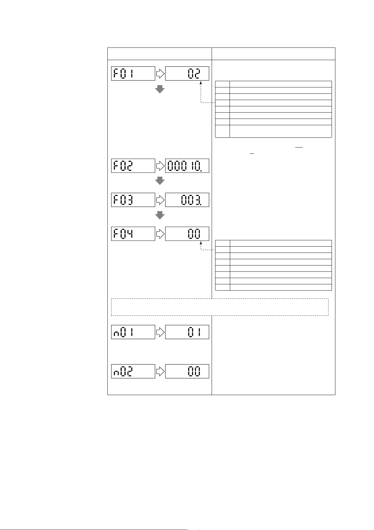
■■
Display Description
After setting the number changing mode, the unit of pulse
weight is set in parameter No. “F01”.
Default : 06
Volume unit in that for the flow rate span ×10
00
Volume unit in that for the flow rate span ×10
01
Volume unit in that for the flow rate span ×10
02
Volume unit in that for the flow rate span ×1
03
Volume unit in that for the flow rate span ×10
04
Volume unit in that for the flow rate span ×10
05
Number of pulses output per second at 100%
06
output
Volume UnitCode
-9
-6
-3
3
6
When pulses are to be output per some liter with the flow
rate span of
m3/h, select “02” since L = 10-3 × m
Set the pulse weight “10” in parameter No. “F02”.
Default : 0
Set the low cut range nearby 0% in parameter No.
“F03”.
Default: (3%)
Setting Range: 0 to 100% (of span)
The pulse width can be set in parameter No. “F04”.
Pulse WidthCode
Default: 00
00
50%DUTY (Max. 1000p/s Min. 0.0001p/s)
01
0.5ms (Max. 1000p/s Min. 0.0001p/s)
02
1ms (Max. 500p/s Min. 0.0001p/s)
03
20ms (Max. 25p/s Min. 0.0001p/s)
04
33ms (Max. 15p/s Min. 0.0001p/s)
05
50ms (Max. 10p/s Min. 0.0001p/s)
06
100ms (Max. 5p/s Min. 0.0001p/s)
Normally, these are all required settings. The following settings are made depending on the applications
that are used.
3
(Flow rate value after damping)
Default: 01
Default: 00
5-8
The pulse output calculation can be set in parameter No.
“n01” by selecting flow rate or flow rate value after
damping.
In case the pulse output transistor should be OFF
ACTIVE, please change the parameter No. in “n02” to
“01”.
IM 1E10C1-E
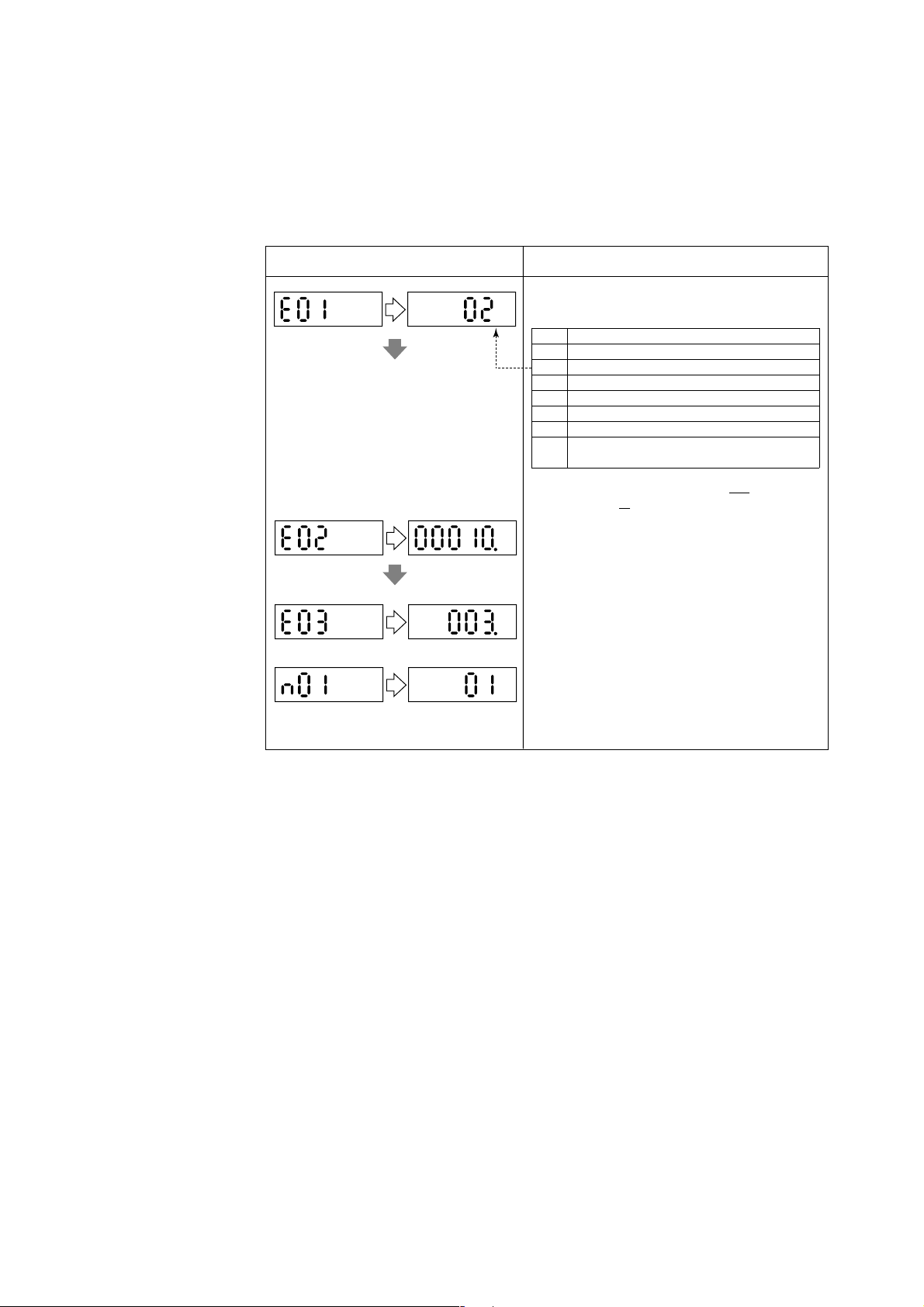
5.5.2 Display of Internal Totalization Values
■■
• By setting a weight per a pulse, flow rate totalized value is shown on the display of
the converter.
(1) Setting Totalization Pulse Weight
Example: To output 10 liter per pulse in flow rate span of m3/h.
Display Description
5. FUNCTION AND DATA SETTINGS
Set the pulse weight unit in parameter No. “E01”.
Defalt : 06
Default : 3%
(Damped flow rate value)
Default : 01
Volume unit in that for the flow rate span ×10
00
Volume unit in that for the flow rate span ×10
01
Volume unit in that for the flow rate span ×10
02
Volume unit in that for the flow rate span ×1
03
Volume unit in that for the flow rate span ×10
04
Volume unit in that for the flow rate span ×10
05
Number of pulses output per second at 100%
06
output
When pulses are to be output per some liter with the flow
Volume UnitCode
rate span of
m3/h, select “02” since L = 10-3 × m
-9
-6
-3
3
6
3
Set the pulse weight “10(l)” in parameter No. “E02”.
Set the low cut range nearby 0% in parameter No. “E03”.
Setting Range: 0 to 100% (of span)
The flow rate totalized value calculation can be set in
parameter No. “n01” by selecting “NO DAMPING” or
“DAMPING”.
5-9
IM 1E10C1-E
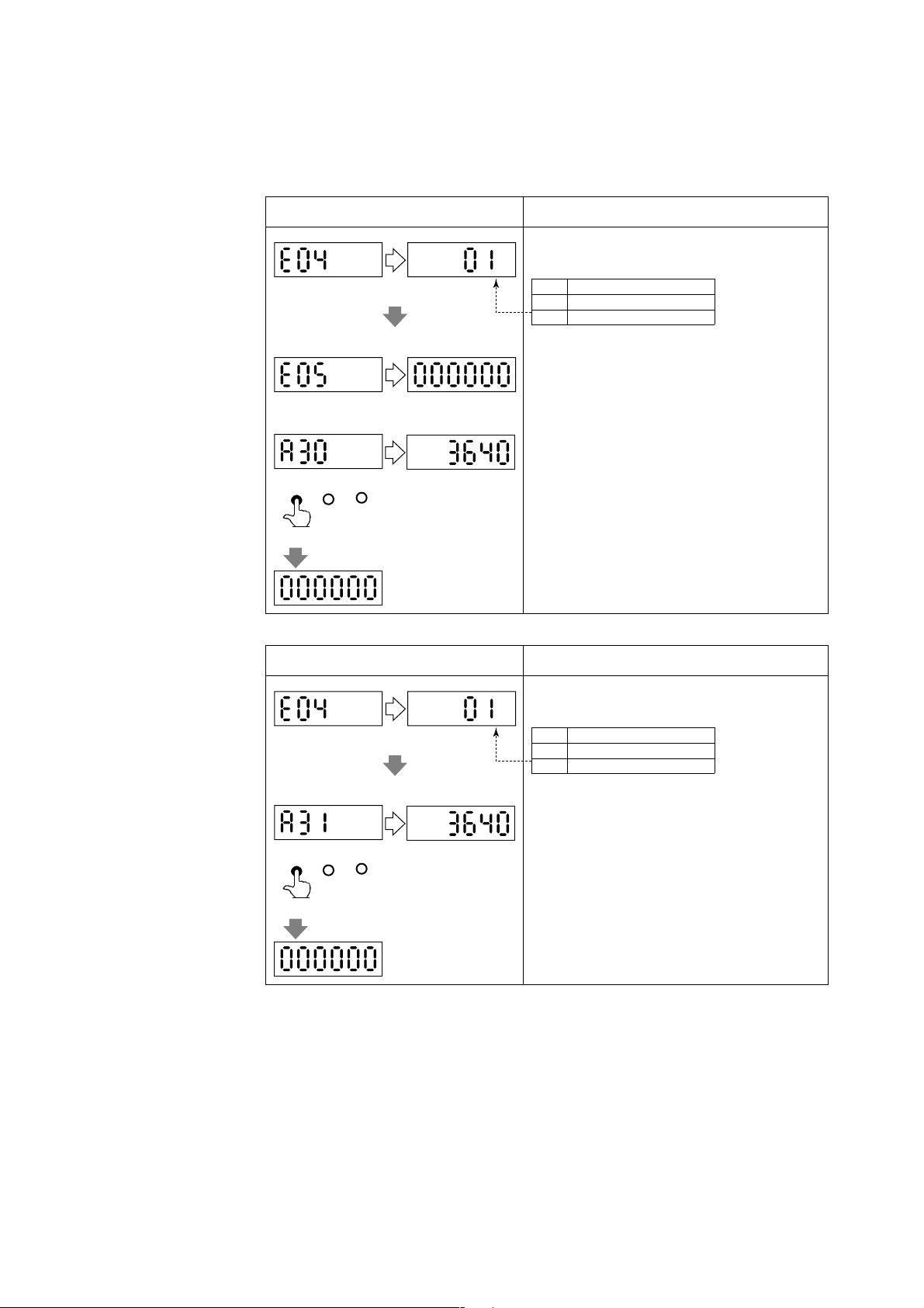
5.5.3 Resetting for Totalization Display
(1) Presetting for Forward Totalization Display
• E04, E05 are used for reset or preset the totalization values of the display.
Display Description
Default: 00 (disabled)
Default: 0
5. FUNCTION AND DATA SETTINGS
The totalization value presetting enable can be selected at
parameter No. “E04”.
ContentCode
00
Totalization preset inhibit
01
Totalization preset enable
The totalization value presetting enable is selected at
parameter number “E05”. The initial value is “0”, if it is
no setting, the function is zero setting.
SET SHIFT INC
(Twice)
(2) Zero-resetting for Reverse Toralization Display
Display Description
Default: 00 (disabled)
SET SHIFT INC
(Twice)
During the A30 :TOTAL (totalization value of flow rate)
is shown, the totalization value display is becoming the
value that is set at parameter number “E05”, by touching
SET key twice.
The totalization value presetting enable can be selected at
parameter No. “E04”.
00
01
During the A31 :REV.TOTAL (totalization value of
reverse flow rate) is shown, the totalization value display
is becoming zero, by touching SET key twice.
ContentCode
Totalization preset inhibit
Totalization preset enable
5-10
IM 1E10C1-E
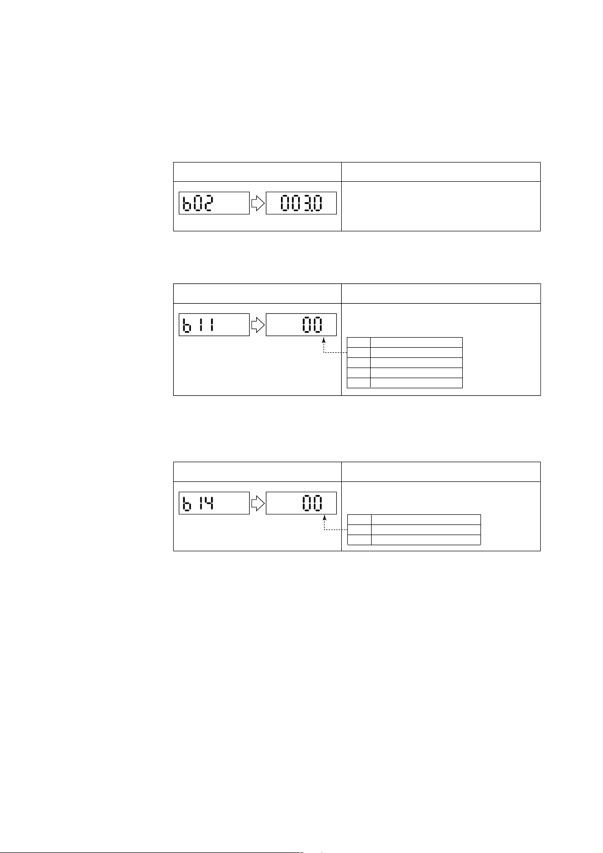
5.5.4 Damping Time Constant
• The time constant can be changed by setting the parameter No. “b02” to suppress a
fluctuation or change a response time.
• The time constant influences to flow rate, pulse output and internal totalization.
However, in case “00” is selected in parameter No. “n01”, the pulse output and
internal totalization are not influenced by it.
Display Description
Default: 3(sec).
5.5.5 Current Output during Alarm Occurrence
• The current output and display values during alarming can be selected in advance.
Display Description
Default: 03
5. FUNCTION AND DATA SETTINGS
The time constant can be set in parameter No. “02”.
Setting Range: 0.5 to 200.0 sec.
The current output value during alarming can be set in
parameter No. “b11”.
Code
00
01
02
03
Content
2.4mA or less
4.0mA
HOLD
21.6mA or more
5.5.6 Reversing Flow Direction
•The flow direction is set to “FORWARD” at the factory. This function enables to set
flow direction from “FORWARD” to “REVERSE”.
Display Description
The flow derection can be set in parameter No. “b14”.
Default: 00
Code
00
01
Content
Forward direction
Reverse direction to flow arrow
5-11
IM 1E10C1-E
 Loading...