

Page 1

Technical
Information
Combining ADMAG AXF
with Existing Remote Type
Magnetic Flowmeters
TI 01E20A02-01E
Company Confidential
Contents
Introduction .................................................................................................................. 2
1. Combining AXF Flowtubes with Existing Converters ...................................... 3
1.1 Combination between AM11 and AXF Flowtubes............................................. 3
1.2 Combination between AE14 and AXF Flowtubes ............................................. 3
1.3 Combination between YMA11 and AXF Flowtubes........................................... 4
2. Combining AXFA Converters with Existing Flowtubes .................................... 7
2.1 Combination between AM Flowtubes and AXFA11........................................... 8
(Combination between AM Flowtubes and AXFA14)
2.2 Combination between AE Flowtubes and AXFA14 ........................................... 9
(Combination between AE Flowtubes and AXFA11)
2.3 Combination between SE Flowtubes and AXFA11 ......................................... 10
2.4 Combination between YM Flowtubes and AXFA11......................................... 11
2.5 Combination between Flowtubes of Other Manufacturers and AXFA11 ......... 13
3. How to Check the Performance of Existing Flowtubes.................................. 16
4. How to Obtain Meter Factor using the Customer's Flow Line ....................... 17
4.1 How to Perform Flow Calibration in Combination with AXFA11 using the
Customer's Facilities ....................................................................................... 17
4.2 How to Obtain Meter Factor by Incorporating the Indicated Flow Rate of the
Existing Converter. .......................................................................................... 18
4.3 How to Obtain Meter Factor According to the Inferred Flow Rates Such as
Valve Openings or Pump Rpm ........................................................................ 19
5. Compatibility with AXFA11 and AXFA14 ....................................................... 20
Appendix. 1 Electrical Connection............................................................................ 21
(1)Combination AXFA11 and FOXBORO 1800 Series ........................................ 22
(2) Combination AXFA11 and FOXBORO 2800 Series ........................................ 24
(3) Combination AXFA11 and F&P 10D1418 Series ............................................ 26
(4) Combination AXFA11 and F&P 10D1419 Series ............................................ 28
(5) Combination AXFA11 and F&P 10D1430 Series ............................................ 29
(6) Combination AXFA11 and F&P 10D1435 (MAGX) Series (6” to 48”).............. 31
(7) Combination AXFA11 and F&P 10D1475 (MINI MAGX) Series...................... 32
(8) Combination AXFA11 and BROOKS 7000 Series .......................................... 33
(9) Combination AXFA11 and BROOKS 7100 Series .......................................... 34
(10) Combination AXFA11 and BROOKS 7400 Series .......................................... 35
(11) Combination AXFA11 and BROOKS 7500 Series .......................................... 36
(12) Combination AXFA11 and KROHNE ALTFLUX X-1000, M900 Series ........... 37
(13) Combination AXFA11 and ROSEMOUNT 8701.............................................. 39
(14) Combination AXFA11 and TAYLOR 1100 Series ............................................ 40
Yokogawa Electric Corporation
2-9-32 Nakacho, Musashino-shi, Tokyo 180, Japan
Tel.: 81-422-52-4443 Fax.: 81-422-52-2018
TI 01E20A02-01E
©Copyright Aug. 2004
1st Edition Aug. 2004
Page 2
<T oc> <Ind>
Introduction
This technical information describes how to combine ADMAG AXF magnetic flowmeters with
existing remote type flowtubes or con verters. A magnetic flo wmeter is used by obtaining a meter
factor , which is a calibration coefficient unique to a flo wtube, according to flo w calibration and then
by setting the meter factor to a conv erter. Values of meter factors depend on the models of
converters to be combined. Therefore, in order to measure flow rates with high accuracy, flow
calibration must be re-performed at the factory. If this is not possible, refer to additional errors and
meter factor conversion coefficients described in this technical inf ormation.
There are various precautions for combinations with e xisting instruments. In some cases , such
instruments cannot be combined or require settings by Yokogaw a's service personnel. Read this
technical information carefully and take appropriate measures.
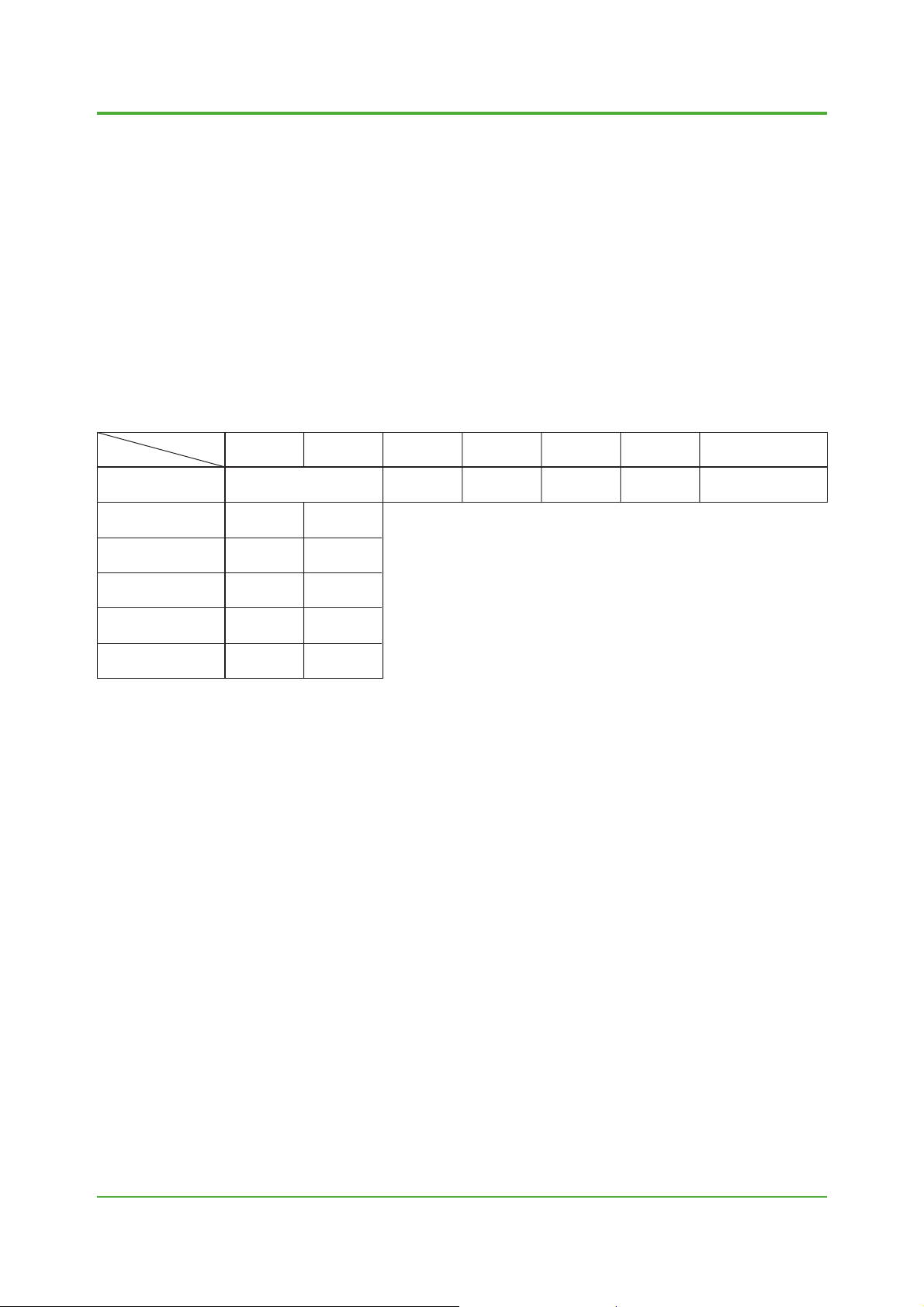
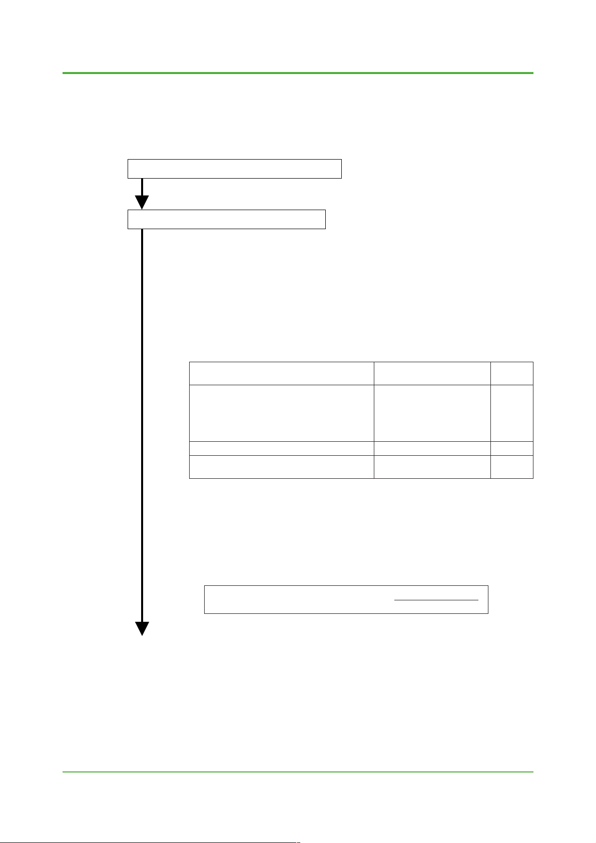
Possible Combinations between Existing Remote Type Flowtubes/Con verters and ADMAG AXF
Series
Converters
Flowtubes
2
AXFA14 AM11AXFA11
Section 1.1
AE14 YMA11SE14
Section 1.2—
Not possible
Section 1.3 Not possibleAXF Flowtube
Converters of Other
Manufacturers
AM Flowtube
AE Flowtube
SE Flowtube
YM Flowtube
Flowtubes of Other
Manufacturers
Section 2.1
See Note in
Section 2.2
Section 2.3
Section 2.4 Not possible
Note: Even if a flowtube is an e xplosion-proof type, the e xplosion-proof capability is not satisfied if the flo wtube is
combined with a different model. If the explosion-proof capability is required, the flowtube must be used in the
combination specified for the same model.
See Note in
Section 2.1
Section 2.2
Not possible
Not possibleSection 2.5
T01.EPS
All Rights Reserved. Copyright © 2004, Yokogawa Electric Corporation
TI 01E20A02-01E 2004-00
Page 3

<T oc> <Ind>
1. Combining AXF Flowtubes with Existing Con verters
Note 1: For combinations between an existing converter and an AXF flowtube, only AM11, AE14 and YMA11 can be
used. Other conv erters (SE14 and converters of other companies) cannot be combined with AXF flowtubes.
Note 2: Even if flow calibration is redone, functions and capabilities are equivalent to those of existing instruments. The
functions unique to AXF such as enhanced dual frequency excitation cannot be used.
1.1 Combination between AM11 and AXF Flowtubes
1.1.1 When newly pur chasing AXF flowtubes
• Issue a Tokuchu request for purchasing AXF flowtubes. In this case, the enhanced dual
frequency excitation function (option codes /HF1 and /HF2) cannot be selected. In the
Tokuchu request, be sure to enter a model name of an existing converter (a full model
and suffix code) and indicate clearly that an AXF flowtube will be combined with this
converter.
• In addition to the regular flow calibration with AXFA converters, flow calibration in
combination with AM11 is performed and then both meter factors are inscribed on the
data plate. Set the meter factor for AM11 to AM11 before operation. The accuracy in this
case will be the same as AM.
Note: Meter factors for combinations diff er , depending on whether an e xisting con v erter is AM11-AS/DH/DB
or AM11-DL. Theref ore, be sure to state a full model and suffix code clearly in a Tokuchu request.
3
1.1.2 When using existing or stock AXF flo wtubes
Combination with AM11-AS, DH or DB
• It is recommended that flow calibration be redone for the AXF flowtubes at Yokogawa's
factory. The accuracy in this case will be the same as AM.
• If flow calibration cannot be redone at Yokogawa's factory, set the meter factors (both
the low MF value and the high MF value) inscribed on AXF flowtubes to AM11 as they
are. The accuracy for reference in this case will be approximately AM accuracy ⫾additional 0.5% for flowtubes for AXFA11 (model name: AXFxxxx-N) and approximately AM
accuracy ⫾additional 1.5% for flowtubes for AXFA14 (model name: AXFxxxx-P).
Combination with AM11-DL
• Flow calibration must be redone for the AXF flowtubes at Yokogawa's factory. The
accuracy in this case will be the same as AM.
• If flow calibration cannot be redone at Yokogawa's factory, contact Yokogawa. Since
meter factors differ substantially for combination with the DL-type, meter factors inscribed on the AXF flowtubes cannot be set for use as they are.
1.2 Combination between AE14 and AXF Flowtubes
Note: Sizes of the flowtubes which can be combined with AE14 are 2.5 mm (0.1 in.) to 400 mm (16 in.) only.
1.2.1 When newly pur chasing AXF flowtubes
• Issue a Tokuchu request for purchasing AXF flowtubes. In this case, the enhanced dual
frequency excitation function (option codes /HF1 and /HF2) cannot be selected. In the
Tokuchu request, be sure to indicate clearly that AXF flowtubes will be combined with
AE14.
• In addition to the regular flow calibration with AXFA converters, flow calibration in
combination with AE14 is performed and then both meter factors are inscribed on the
data plate. Set the meter factor for AE14 to AE14 before operation. The accuracy in this
case will be the same as AE.
All Rights Reserved. Copyright © 2004, Yokogawa Electric Corporation TI 01E20A02-01E
2004-00
Page 4

<T oc> <Ind>
1.2.2 When using existing or stock AXF flo wtubes
• It is recommended that flow calibration be redone for the AXF flowtubes at Yokogawa's
factory. The accuracy in this case will be the same as AE.
• If flow calibration cannot be redone at Yokogawa's factory, set the meter factors (both
the low MF value and the high MF value) inscribed on AXF flowtubes to AE14 as they
are. The accuracy for reference in this case will be approximately AE accuracy ⫾addi-
tional 0.5% for flowtubes for AXFA14 (model name: AXFxxxx-P) and approximately AE
accuracy ⫾additional 1.5% for flowtubes for AXFA11 (model name: AXFxxxx-N).
1.3 Combination between YMA11 and AXF Flowtubes
1.3.1 When newly pur chasing AXF flowtubes
• Issue a Tokuchu request for purchasing AXF flowtubes. In this case, the enhanced dual
frequency excitation function (option codes /HF1 and /HF2) cannot be selected. In the
Tokuchu request, be sure to indicate clearly that AXF flowtubes will be combined with
existing YMA11 converters.
• In addition to the regular flow calibration with AXFA converters, flow calibration in
combination with YMA11 is performed and then both meter factors are inscribed on the
data plate. Set the meter factor for YMA11 and an excitation current value to YMA11
before operation. Obtain a relevant excitation current value from Tables 1.3.1 to 1.3.3.
The accuracy in this case will be the same as YM.
4
1.3.2 When using existing or stock AXF flo wtubes
• It is recommended that flow calibration be redone for the AXF flowtubes at Yokogawa's
factory. The accuracy in this case will be the same as YM.
• If flow calibration cannot be redone at Yokogawa's factory and if a flowtube for AXFA11
(AXFxxxx-N) is used, obtain a necessary excitation current value and an approximate
meter factor value from Tables 1.3.1 to 1.3.3, and combine the flowtube with YMA11.
The meter factor for YMA11 is obtained by multiplying the low meter factor (the meter
factor inscribed on the "METER FACTOR L" section of the data plate) of the AXF
flowtube with a coefficient in Tables 1.3.1 to 1.3.3. Although the accuracy in this case is
not guaranteed, it will be approximately YM accuracy ⫾additional 2% as a reference.
Also, the excitation current value needs to be set to YMA11.
• Flowtubes for AXFA14 (AXFxxxx-P) cannot be combined with YMA11 without redoing
flow calibration.
• AXF flowtubes with the size of 32 mm (1.25 in.), 65 mm (2.5 in.) or 125 mm (5 in.) cannot
be combined with YMA11.
All Rights Reserved. Copyright © 2004, Yokogawa Electric Corporation
TI 01E20A02-01E 2004-00
Page 5
<T oc> <Ind>
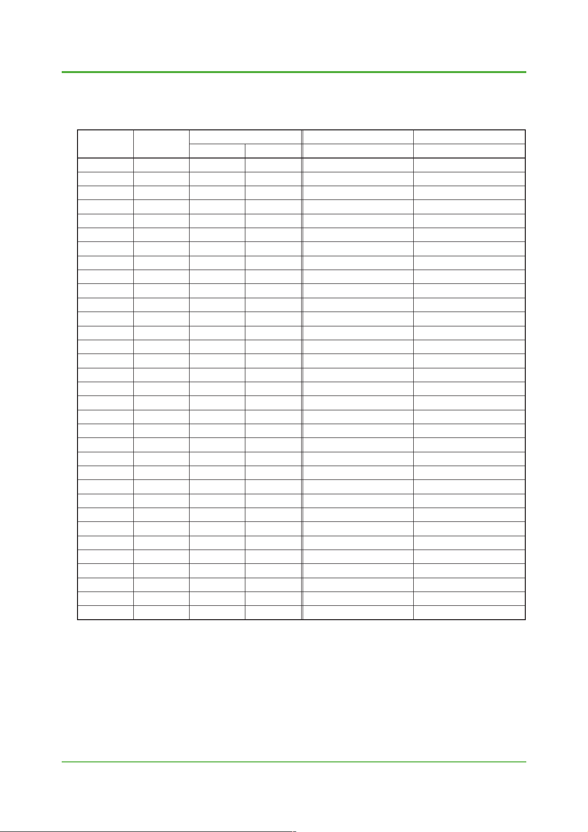
5
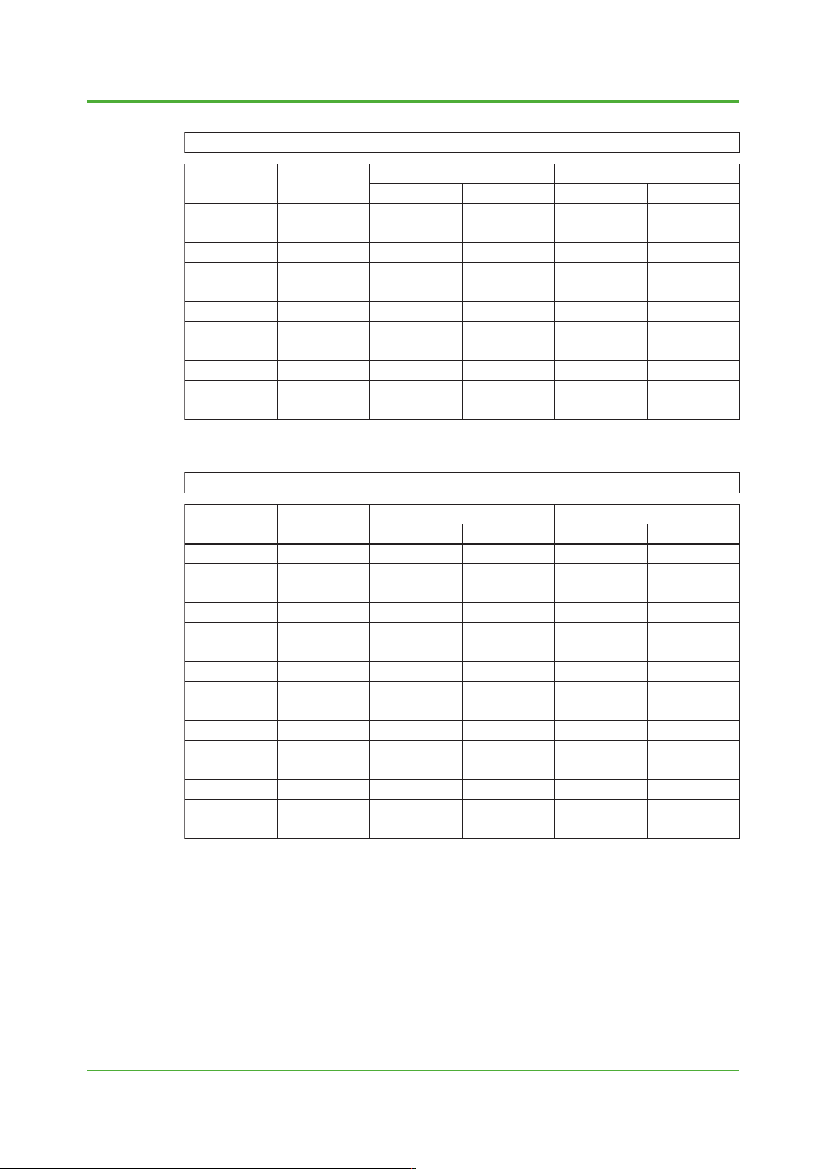
Table 1.3.1 Combination between AXF Ceramic Lining Flowtubes and YMA11
Meter factor for YMA11 = Low meter factor for AXF flowtube ⫻ coefficient in the table below
Size of AXF
Flowtube
[mm (in.)]
2.5 (0.1)
5 (0.2)
10 (0.4)
15 (0.5)
25 (1.0)
40 (1.5)
50 (2.0)
80 (3.0)
100 (4.0)
150 (6.0)
200 (8.0)
YMA11 Excitation
Current Setting
Value (A)
0.12
0.13
0.22
0.22
0.14
0.13
0.12
0.16
0.14
0.11
0.12
Coefficient in 1/8 Mode Excitation Coefficient in 1/2 Mode Excitation
60 Hz Area 50 Hz Area50 Hz Area 60 Hz Area
1.0304
0.9771
0.6542
0.9589
0.9756
0.9723
0.9697
0.9701
0.9619
0.9672
0.9666
1.0313
0.9757
0.9542
0.9584
0.976
0.9724
0.9691
0.9688
0.9602
0.9661
0.9661
1.0232
0.9760
0.95
0.9589
0.9748
0.9732
0.9683
0.9673
0.9567
0.9639
0.9596
Table 1.3.2 Combination between AXF PF A Lining Flowtubes and YMA11
Meter factor for YMA11 = Low meter factor for AXF flowtube ⫻ coefficient in the table below
Size of AXF
Flowtube
[mm (in.)]
2.5 (0.1)
5 (0.2)
10 (0.4)
15 (0.5)
25 (1.0)
40 (1.5)
50 (2.0)
80 (3.0)
100 (4.0)
150 (6.0)
200 (8.0)
250 (10.0)
300 (12.0)
350 (14.0)
400 (16.0)
For " * " sections in the table, contact Yok ogaw a.
YMA11 Excitation
Current Setting
Value (A)
0.12
0.14
0.23
0.23
0.15
0.13
0.13
0.17
0.14
0.11
0.12
0.5
0.5
0.5
0.5
Coefficient in 1/8 Mode Excitation Coefficient in 1/2 Mode Excitation
60 Hz Area 50 Hz Area50 Hz Area 60 Hz Area
1.0127
0.9786
0.94
0.9423
0.9755
0.9727
0.9728
0.9741
0.9635
0.9796
0.9767
0.9924
0.9864
*
0.9844
1.0162
0.9788
0.9403
0.9419
0.976
0.9719
0.9725
0.9726
0.9625
0.9779
0.9759
0.9925
0.9855
*
0.9841
1.0092
0.9763
0.9351
0.9398
0.9746
0.9716
0.9715
0.9701
0.9562
0.9679
0.9756
0.9595
0.9435
*
0.9367
1.0205
0.9730
0.9487
0.9583
0.9746
0.9717
0.9675
0.9658
0.9546
0.9603
0.9550
T02.EPS
1.006
0.975
0.9335
0.9399
0.9747
0.9708
0.9705
0.9674
0.9526
0.9613
0.9468
0.9483
0.9265
*
0.9193
T03.EPS
All Rights Reserved. Copyright © 2004, Yokogawa Electric Corporation TI 01E20A02-01E
2004-00
Page 6

<T oc> <Ind>
6
Table 1.3.3 Combination between AXF P ol yurethane Lining Flowtubes and YMA11
Meter factor for YMA11 = Low meter factor for AXF flowtube ⫻ coefficient in the table below
Size of AXF
Flowtube
[mm (in.)]
25 (1.0)
40 (1.5)
50 (2.0)
80 (3.0)
100 (4.0)
150 (6.0)
200 (8.0)
For " * " sections in the table, contact Yok ogawa.
YMA11 Excitation
Current Setting
Value (A)
0.2
*
*
0.23
0.2
0.15
0.17
Coefficient in 1/8 Mode Excitation Coefficient in 1/2 Mode Excitation
0.9841
*
*
0.9836
0.9562
0.9845
0.9818
60 Hz Area 50 Hz Area50 Hz Area 60 Hz Area
0.9835
*
*
0.9821
0.9553
0.9827
0.9802
0.9840
*
*
0.972
0.9491
0.9742
0.9621
0.9838
*
*
0.9701
0.9452
0.9684
0.9519
T04.EPS
All Rights Reserved. Copyright © 2004, Yokogawa Electric Corporation
TI 01E20A02-01E 2004-00
Page 7
<T oc> <Ind>
2. Combining AXF A Con verters with Existing Flowtubes
Note: In some cases, these instruments cannot be combined. Ev en if they can be combined, it is strongly recommended
to redo flow calibration if existing flowtubes are Yokoga w a's products. The accuracy in this case will be the
standard accuracy of the existing flowtubes. If flow calibration cannot be redone or if AXFA conv erters need to be
combined with flowtubes of other manufacturers, meter f actors based on calculations or on-site actual flow tests
shall be incorporated. Note that the accuracy is not guaranteed in this case. It may also not be possible to provide
additional errors for reference.
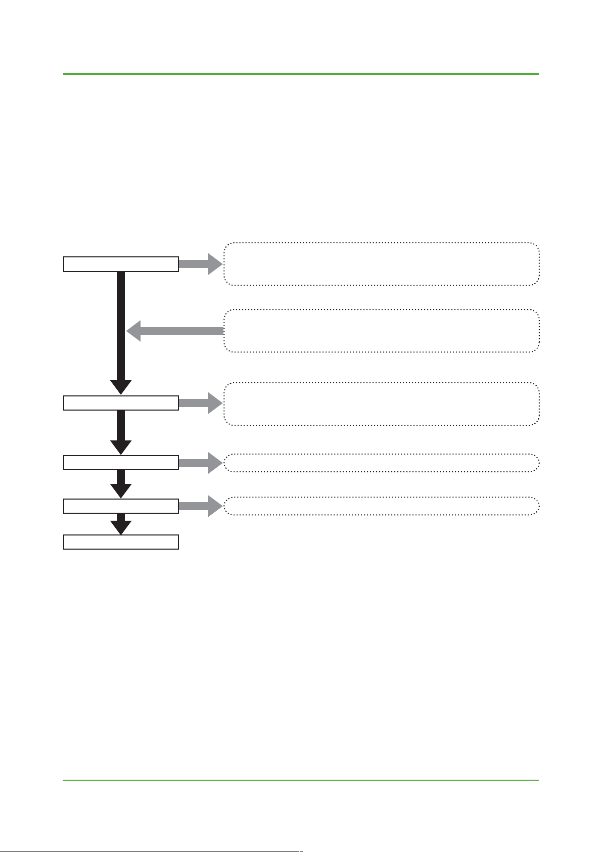
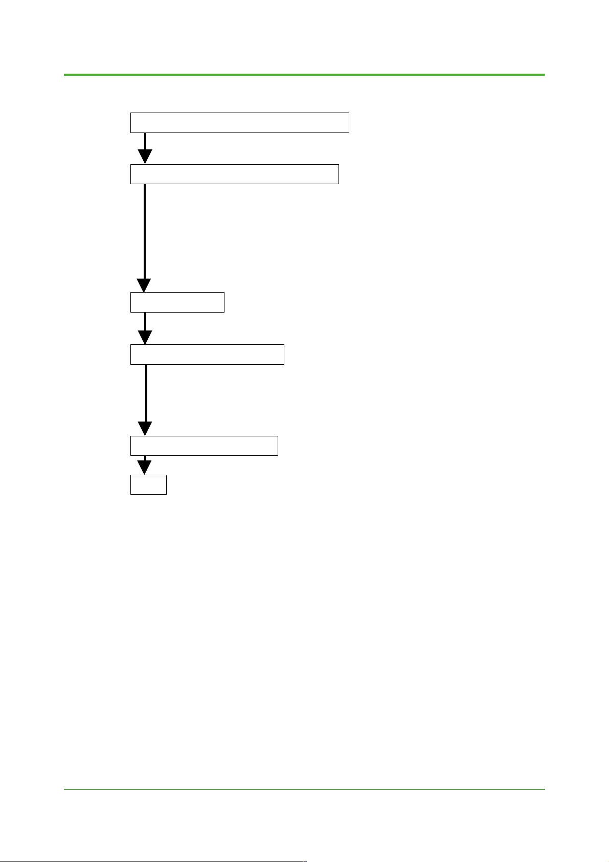
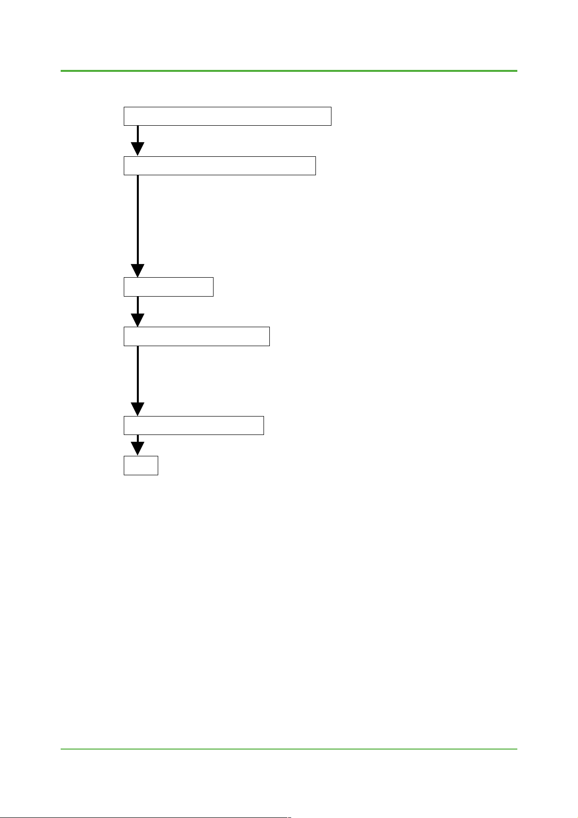
Outline of procedures
• For details, see Sections 2.1 to 2.5.
(1) Continuity and insulation check of excitation coils
Flowtube performance check
(2) Continuity and insulation check of signal lines
(See Chapter 3 "How to Check the Performance of Existing Flowtubes.")
Obtain a meter factor:
(1) Obtain a meter factor by referring to Sections 2.1 to 2.5 and Chapter 4.
(2) For redoing flow calibration at the factory, request Yokogawa.
7
Wiring
AXFA parameter setting
Automatic zero adjustment
End
(1) For signal cables, use dedicated signal cable AXFC. Note that AM011 cable
and YM011 cable can be used if insulation and continuity are not deteriorated.
(2) Connect flowtubes and converters.
(1) For parameter setting, see Sections 2.1 to 2.5 and the user's manual for AXFA.
Perform the automatic zero adjustment by referring to the user's manual for AXFA.
F01.EPS
All Rights Reserved. Copyright © 2004, Yokogawa Electric Corporation TI 01E20A02-01E
2004-00
Page 8
<T oc> <Ind>
2.1 Combination between AM Flowtubes and AXFA11
2.1.1 Flowtube performance c heck
Based on Chapter 3 "How to Check the Performance of Existing Flowtubes," check
that an existing flowtube is not damaged.
2.1.2 Obtaining the meter factors
Obtain the meter factors by either of the following two methods a) or b) depending on
the situation:
a) By obtaining the meter factors by redoing flow calibration at Yokogawa's
factory
The accuracy in this case will be the same as AM.
b) By using the meter factors of AM
• For the sizes from 2.5 mm (0.1 in.) to 1000 mm (40 in.) and the sizes from 1100
mm (44 in.) to 2600 mm (104 in.) style A or style B (model code: AM5xxx.....*A
or *B), the meter factors inscribed on AM flowtubes can be set to AXFA11 as
they are. The accuracy for reference in this case will be approximately AM
accuracy ⫾additional 0.5%.
• If the existing flowtube is 1100 mm (44 in.) to 2600 mm (104 in.) style C (model
code: AM5xxx.....*C), the AM's meter factor cannot be set to AXFA11 as it is,
because the meter factor in combination with AXFA11 differs substantially.
Contact Yokogawa for how to deal with such situations.
8
2.1.3 Wiring
Connect the AM flowtube with AXFA11.
The wiring is the same as in the case of connecting AXF flowtubes with AXFA11.
2.1.4 Parameter setting
Set the following parameters to AXFA11:
• Select "ADMAG" in the parameter "C30: Select Flow Tube." Flowtubes with the
size of 400 mm (16 in.) or smaller are driven with dual frequency excitation,
while those with the size of 500 mm (20 in.) or larger are driven with pulsed DC
calculation. The enhanced dual frequency excitation function cannot be used.
• Set both "C21: Low MF" and "C22: High MF" as meter factors for flowtubes with
the sizes from 2.5 mm (0.1 in.) to 400 mm (16 in.). Set "C21: Low MF" as the
meter factor for flowtubes with the sizes from 500 mm (20 in.) to 2600 (104 in.)
mm, and set 1.0000 to "C22: High MF."
• For the sizes from 1100 mm (44 in.) to 2600 mm (104 in.), select "No" in the
parameter "J30: Power Synch" and set "49.00" to "J31: Power Frequency."
• For details on setting parameters other than the above, follow the user's
manual for AXFA11.
2.1.5 Zero adjustment
Perform the automatic zero adjustment according to the user's manual for AXFA11.
End
Note: Combinations between AM flo wtubes and AXFA14 can also be operated using the same
procedure. How ev er, in "b) By using the meter factors of AM" of Section 2.1.2 "Obtaining the
meter factors," the accuracy f or ref erence will be appro ximately AM accuracy ⫾additional 1.5%.
Moreover , in the case of the siz es from 250 mm (10 in.) to 400 mm (16 in.), output fluctuations
may become larger than in the case of operations using AXFA11 due to EMF differences.
Note that combinations between AM flowtubes and AXFA14 are only possible for the sizes from
2.5 mm (0.1 in.) to 400 mm (16 in.).
There is no need to set the parameter "C30: Select Flo w Tube" (there is no parameter "C30" in
AXFA14).
All Rights Reserved. Copyright © 2004, Yokogawa Electric Corporation
TI 01E20A02-01E 2004-00
Page 9
<T oc> <Ind>
2.2 Combination between AE Flowtubes and AXFA14
2.2.1 Flowtube performance chec k
Based on Chapter 3 "How to Check the Performance of Existing Flowtubes," check
that an existing flowtube is not damaged.
2.2.2 Obtaining the meter factors
Obtain the meter factors by either of the following two methods a) or b) depending on
the situation:
a) By obtaining the meter factors by redoing flow calibration at Yokogawa's
factory
The accuracy in this case will be the same as AE.
b) By using the meter factors of AE
The meter factors inscribed on AE flowtubes can be set to AXFA14 as they are.
The accuracy for reference in this case will be approximately AE accuracy
⫾additional 0.5%.
2.2.3 Wiring
Connect the AE flowtube with AXFA14.
The wiring is the same as in the case of connecting AXF flowtubes with AXFA14.
2.2.4 Parameter setting
Set the following parameters to AXFA14:
• Set both "C21: Low MF" and "C22: High MF" as meter factors.
• For details on setting parameters other than the above, follow the user's
manual for AXFA14.
Note: AE flowtubes are driv en with dual frequency e xcitation. The enhanced dual frequency e xcitation
function cannot be used.
9
2.2.5 Zero adjustment
Perform the automatic zero adjustment according to the user's manual for AXFA14.
End
Note: Combinations between AE flo wtubes and AXFA11 can also be operated using the same
procedure. Ho we v er , in "b) By using the meter factors of AE" of Section 2.2.2 "Obtaining the
meter factors," the accuracy f or ref erence will be approximately AE accur acy ⫾additional 1.5%.
Select "ADMAG AE" in the parameter "C30: Select Flo w Tube" for AXF A11.
All Rights Reserved. Copyright © 2004, Yokogawa Electric Corporation TI 01E20A02-01E
2004-00
Page 10
<T oc> <Ind>
2.3 Combination between SE Flowtubes and AXFA11
2.3.1 Flowtube performance c heck
Based on Chapter 3 "How to Check the Performance of Existing Flowtubes," check
that an existing flowtube is not damaged.
2.3.2 Obtaining the meter factor
Obtain the meter factor by either of the following two methods a) or b) depending on
the situation:
a) By obtaining the meter factor by redoing flow calibration at Yokogawa's
factory
The accuracy in this case will be the same as SE.
b) By obtaining meter factor using the customer's flow line according to
Chapter 4
Follow Section 2.3.3 "Wiring" and Section 2.3.4 "Parameter setting" before
obtaining meter factor according to the actual flow test.
2.3.3 Wiring
Connect the SE flowtube with AXFA11.
The wiring is the same as in the case of connecting AXF flowtubes with AXFA11.
2.3.4 Parameter setting
Set the following parameters to AXFA11:
• Select "ADMAG SE" in the parameter "C30: Select Flow Tube." SE Flowtubes
are driven with pulsed DC calculation.
• Set the obtained meter factor to "C21: Low MF." Set 1.0000 to "C22: High MF."
• For details on setting parameters other than the above, follow the user's
manual for AXFA11.
10
2.3.5 Zero adjustment
Perform the automatic zero adjustment according to the user's manual for AXFA11.
End
Note 1: Meter factors of SE flowtubes cannot be used for setting as they are, as meter factors diff er substantially in the
combinations between SE flowtubes and AXF A11.
Note 2: AXFA14 cannot be combined with SE flowtubes, as it cannot drive the SE flowtubes .
All Rights Reserved. Copyright © 2004, Yokogawa Electric Corporation
TI 01E20A02-01E 2004-00
Page 11
<T oc> <Ind>
2.4 Combination between YM Flowtubes and AXFA11
2.4.1 Flowtube performance chec k
Based on Chapter 3 "How to Check the Performance of Existing Flowtubes," check
that an existing flowtube is not damaged.
2.4.2 Obtaining the meter factor
Obtain the meter factor by either one of the following three methods a), b) and c),
depending on the situation:
a) By obtaining the meter factor by redoing flow calibration at Yokogawa's
factory
The accuracy in this case will be the same as YM.
b) By calculating from the meter factor of YM
The accuracy for reference will be approximately YM accuracy
(1) Read the meter factor in 1/8 mode (standard mode) and 50 Hz from the data
plate of a YEWMAG flowtube.
(2) The meter factor is obtained by multiplying the YM meter factor in 1/8 mode
and 50 Hz by a coefficient determined for each size shown in Table 2.4
"Meter Factor Calculation Coefficient Table".
Example:
c) By obtaining meter factor using the customer's flow line according to
Chapter 4
Follow Section 2.4.3 "Wiring" and Section 2.4.4 "Parameter setting" before
obtaining meter factor according to the actual flow test.
YM102 1/8 mode, 50 Hz Meter factor: 0.2800
50 Hz area:
Meter factor: 0.2800 ⫻ 1.0825 = 0.3031
60 Hz area:
Meter factor: 0.2800 ⫻ 1.0820 = 0.3030
11
⫾additional 1%.
2.4.3 Wiring
Connect the YM flowtube with AXFA11.
The wiring is the same as in the case of connecting AXF flowtubes with AXFA11.
Note that, if BARD is used for a YM explosion-proof type flowtube, remove the BARD
and use the flowtube as a non-explosion-proof type product. This combination
cannot satisfy the requirements of explosion-proof capabilities.
2.4.4 Parameter setting
Set the following parameters to AXFA11:
• Select "YEWMAG" in the parameter "C30: Select Flow Tube."
• Check the software revision number of AXFA11 which is indicated in the
parameter "J50: Software Rev No."
If the revision number is "R1.05" or "R1.08":
Select "Low" in the service parameter (not disclosed) "U15: 4-20mA Sel."
Be sure to contact Yokogawa for the service parameter setting. Pulsed DC
calculations apply to all sizes.
If the revision number is other than "R1.05" or "R1.08":
There is no need to set "U15: 4-20mA Sel." Pulsed DC calculations automatically apply to all sizes by selecting "YEWMAG" in the parameter "C30:
Select Flow Tube" as above.
• Set the obtained meter factor to "C21: Low MF." Set 1.0000 to "C22: High MF."
• For the sizes from 1100 mm (44 in.) to 2600 mm (104 in.), select "No" in the
parameter "J30: Power Synch" and set "49.00" to "J31: Power Frequency."
• For details on setting parameters other than the above, follow the user's
manual for AXFA11.
(To the next page)
All Rights Reserved. Copyright © 2004, Yokogawa Electric Corporation TI 01E20A02-01E
2004-00
Page 12
<T oc> <Ind>
2.4.5 Zero adjustment
Perform the automatic zero adjustment according to the AXFA11 user's manual.
End
Note: AXFA14 cannot be combined with YM flowtubes , as it cannot oper ate the YM flowtubes.
Table 2.4 List of Meter Factor Calculation Coefficients
50 Hz Area 60 Hz Area
YM102
YM104
YM106
YM115
YM202
YM204
YM205
YM208
YM210
YM315
YM320
YM325
YM330
YM335
YM340
YM405
YM406
YM407
YM408
YM409
1.0825
1.0541
1.0417
1.1184
1.0633
1.0181
1.0124
1.0120
1.0124
1.0095
1.0053
1.0185
1.0251
1.0250
1.0506
1.0180
1.0195
1.0224
1.0252
1.0198
1.0820
1.0545
1.0448
1.1185
1.0633
1.0170
1.0123
1.0122
1.0152
1.0098
1.0065
1.0170
1.0249
1.0263
1.0537
1.0179
1.0201
1.0217
1.0254
1.0206
T05.EPS
12
All Rights Reserved. Copyright © 2004, Yokogawa Electric Corporation
TI 01E20A02-01E
2004-00
Page 13
<T oc> <Ind>
2.5 Combination between Flowtubes of Other Manufacturer s and AXFA11
Note: It may not be possible to operate some flowtubes of other manuf acturers due to the diff erence in magnetic circuits .
Although the coil resistance of a flowtube must be 240 ⍀ or less, it ma y not be possib le to operate the flowtube
even if the resistance is 240 ⍀ or less. Especially, if the excitation current of an existing model is designed to be
0.26 mA or less, it is more likely that the flowtube cannot be driven by AXFA11.
2.5.1 Flowtube performance chec k
Based on Chapter 3 "How to Check the Performance of Existing Flowtubes," check
that an existing flowtube is not damaged.
2.5.2 Obtaining the meter factor
Obtain the meter factor by one of the following three methods a), b) and c), depending on the situation:
a) By obtaining meter factor using the customer's flow line according to
Chapter 4
Follow Section 2.5.3 "wiring" and Section 2.5.4 "Parameter setting" before
obtaining meter factor according to the actual flow test.
b) By obtaining meter factor through calculation
The calculated meter factor is an approximation. Calculations must be performed
when it is difficult to obtain a meter factor according to the actual flow test.
Accuracy for reference cannot be provided.
13
Driving methods of existing flowtubes
(Known) Model Name
FOXBORO 1800 and 2800 series
Reference voltage method
Flowtube inscribed with C/F/P
Flowtube inscribed with
generated EMF
Method
* FOXBORO 1800 and 2800 series have two types: C/F/P is inscribed on one
type, while the generated EMF is inscribed on the other. Check the types
shown in the data plate. Both C/F/P and the generated EMF may be inscribed
on some models. In this case, use C/F/P for calculation.
b.1) Reference voltage method
Reference voltage ("Reference.v") is inscribed on the data plate or CP unit
(open the terminal box cover). Calculate the meter factor using the reference
voltage:
Meter factor for FOXBORO 1800 and 2800 series =
Reference voltage (v)
5 ⫻ excitation current
Relevant
Section
b.1)
b.2)
b.3)
T06.EPS
(To the next page)
All Rights Reserved. Copyright © 2004, Yokogawa Electric Corporation TI 01E20A02-01E
2004-00
Page 14

<T oc> <Ind>
b.2) Flowtube inscribed with C/F/P
If C/F/P is inscribed on the data plate, calculate the meter factor as follows:
Meter factor =
10 ⫻ span flow velocity (m/s)
C ⫻ F
b.3) Flowtube inscribed with generated EMF
If the generated EMF is inscribed on the data plate and if the excitation
current value is already known, calculate the meter factor as follows.
Meter factor =
Excitation current value of an existing instrument
Generated EMF per 1 m/s
How to obtain the generated EMF per 1 m/s:
14
Example)
The generated EMF of 0.0540 mV (m3/h) means that "the EMF to
The flow velocity for size 25 mm (1 in.) when the flow rate is 1 m
where,
D: Nominal size (to be set in units of m)
Q: Flow rate (to be set in m
Since the generated EMF for 1 m
If the size is 25 mm (1 in.) and the generated EMF is 0.0540 mV (m3/h):
be generated when the flow rate is 1 m
Flow velocity V(m/s) = ⫻Q(m3/s)
= ⫻ (m
generated EMF for 1 m/s will be:
0.0540 mV⫻ = 0.0954 mV
c) By using an already-known approximate meter factor
Approximate meter factors of the FOXBORO 1800 and 2800 series are already
known. They are shown in Appendix 1 "Wiring". Since these values are approximations, they shall be used when it is difficult to obtain meter factors using actual
flow tests or through calculations. Accuracy for reference cannot be provided.
2.5.3 Wiring
Connect the flowtubes of other manufacturers with AXFA11. For reference, see
Appendix 1 "Wiring" which contains known and available information.
2.5.4 Parameter setting
Set the following parameters to AXFA11:
• Check the software revision number of AXFA11 which is indicated in the
parameter "J50: Software Rev No."
If the revision number is "R1.05" or "R1.08":
(1) Select "YEWMAG" or "Calibrator" in the parameter "C30: Select Flow Tube":
"YEWMAG" if the flowtube's coil resistance is 60 ⍀ or less.
"Calibrator" if the flowtube's coil resistance is 61 ⍀ to 240 ⍀.
(2) Select "Low" in the service parameter (not disclosed) "U15: 4-20mA Sel." Be
sure to contact Yokogawa for the service parameter setting. Pulsed DC
calculations apply to all sizes.
If the revision number is other than "R1.05" or "R1.08":
(1) Select "YEWMAG" or "Other" in the parameter "C30: Select Flow Tube":
"YEWMAG" if the flowtube's coil resistance is 60 ⍀ or less.
"Other" if the flowtube's coil resistance is 61 ⍀ to 240 ⍀.
There is no need to set "U15: 4-20mA Sel." Pulsed DC calculations automatically apply to all sizes by selecting "YEWMAG" or "Other" in the parameter
"C30: Select Flow Tube."
1
0.566
4
2
π
(m)
D
4
3.14⫻(0.025(m))
3
/h (= 0.566 m/s) is 0.054 mV, the
3
/h is 0.0540 mV."
1
3
2
3600
/s)=0.566(m/s)
3
/s)
3
/h:
(To the next page)
All Rights Reserved. Copyright © 2004, Yokogawa Electric Corporation
TI 01E20A02-01E
2004-00
Page 15

<T oc> <Ind>
15
• Set the obtained meter factor to "C21: Low MF." Set 1.0000 to "C22: High MF."
• For details on setting parameters other than the above, follow the user's
manual for AXFA11.
2.5.5 Zero adjustment
Perform the automatic zero adjustment according to the user's manual for AXFA11.
End
Note: AXFA14 cannot be combined with flowtubes of other manufacturers .
All Rights Reserved. Copyright © 2004, Yokogawa Electric Corporation TI 01E20A02-01E
2004-00
Page 16

<T oc> <Ind>
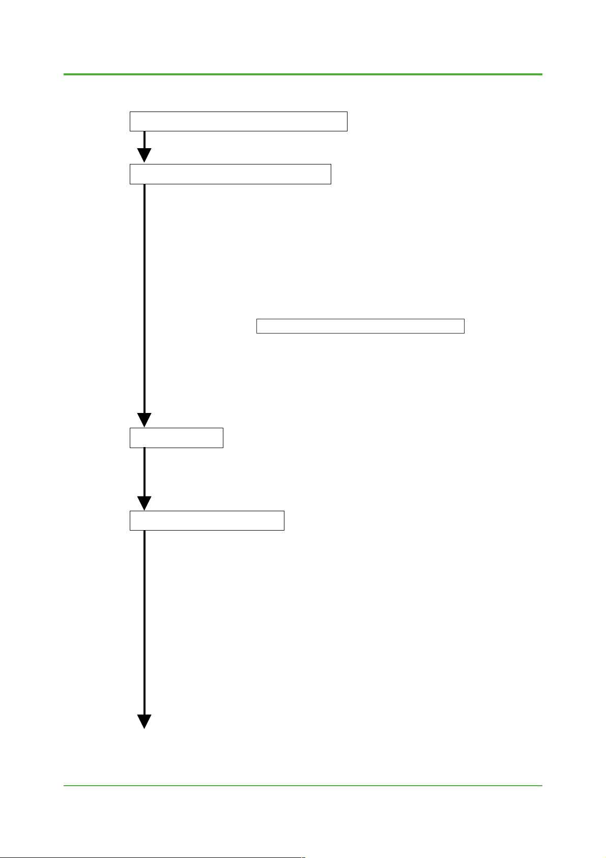
3. How to Chec k the Performance of Existing Flowtubes
(1) Repair any abnormality in the external appearance.
(2) Open the terminal box and repair any abnormality (for example, contamination
External appearance check
Continuity and insulation
check of the flowtube's
excitation coil
Continuity and insulation
check of signal lines
due to liquid infiltration or abnormal seal surface).
* If the flowtube is a Yokogawa product, contact Yokogawa when repair is
required. Otherwise, contact the relevant manufacturer.
(1) If the flowtube is a Yokogawa product, the coil resistance is between several ⍀
to approximately 100 ⍀. Check if the coil resistance is between these values
using a multimeter. In case of other manufacturer's product, it may be possible
to drive the flowtube using the AXFA11 converter as long as the coil resistance
is 240 ⍀ or less.
(2) Check if the coil insulation is 1 M⍀ or more using a 500 V DC megohmmeter.
(1) If the flowtube cannot be taken out from the pipeleine:
It is not possible to know the exact status of a signal line. On the assumption
that the existing flowmeter is operating properly in flow measurement, check
the status of the flowtube as follows:
• If the pipe is filled with the fluid, the resistance between A/B signal terminals
and the grounding is several hundred ⍀ to several dozen k⍀ respectively (to
be measured by a multimeter).
• If the resistance between the A signal terminal and the grounding is
substantially different from the resistance between the B signal terminal and
the grounding (more than double), it is necessary to take out the flowtube
from the pipeline and check the flowtube (using the multimeter) as there
may be an electrode insulation failure or adhesion on the surface of an
electrode.
(2) If the flowtube can be taken out from a pipeline:
• Check the lining surface and remove adhesions, if any.
• Confirm that there is no abnormality on the lining .
• Check the signal line continuity between the electrode surface and the
terminals.
• Use a multimeter or a megohmmeter to check if the insulation between the
signal terminals and the grounding is more than 100 times the wetted
electrode resistance (between A and C or between B and C, whichever is
greater). For example, 1 M⍀ or more when the wetted electrode resistance
is 10 k⍀.
16
End
All Rights Reserved. Copyright © 2004, Yokogawa Electric Corporation
F03.EPS
TI 01E20A02-01E 2004-00
Page 17

<T oc> <Ind>
4. How to Obtain Meter F actor using the Customer's Flow Line
This chapter describes the following three methods to obtain meter f actor using the customer's
flow line by means of AXFA11 and an existing flowtube:
• Flow calibration in combination with AXFA11 using the customer's facilities
• Obtaining meter factor by incorporating the indicated flow rate of the existing con v erter.
• Using inferred flow rate such as valve openings or pump rpm
4.1 How to P erform Flow Calibration in Combination with AXFA11 using the Customer's Facilities
This method can be used if there is a tank or other vessel which can serve as a volumetric
standard, or if another flow meter can be used as a master meter . The accur acy f or ref erence in
this case will be more than three times the accuracy of the volumetric standard or the reference
meter, or the nominal accuracy of the flo wtube, whiche v er is greater . As a rule, calibration should
be performed by Y okoga wa's service personnel.
17
4.1.1 Parameter setting
Set the size and span to AXFA11. The span shall be 1.5 to 2 times the flow rate (the
same span as the one for the master meter if the master meter method is used). In
addition, set the parameters according to any combination with relevant models in
Chapter 2. For "C21: Low MF," set 1.0000 at first temporarily.
4.1.2 Zero adjustment
Before allowing the fluid to flow, see the user's manual for AXFA11 and perform the
automatic zero adjustment.
4.1.3 Measuring flow and calculating the meter factor
Allow the fluid to flow and calculate the new meter factor as follows:
New meter factor = old meter factor ⫻
Use 1.0000, which was temporarily set to the old meter factor, to calculate the new
meter factor. After setting the new meter factor, confirm that the flow indication is
correct. If the flow indication is not correct, repeat the above procedure and incorporate the new meter factor.
Indicated value of AXFA11
(or indicated value of the master meter)
Volumetric standard
All Rights Reserved. Copyright © 2004, Yokogawa Electric Corporation TI 01E20A02-01E
2004-00
Page 18

<T oc> <Ind>
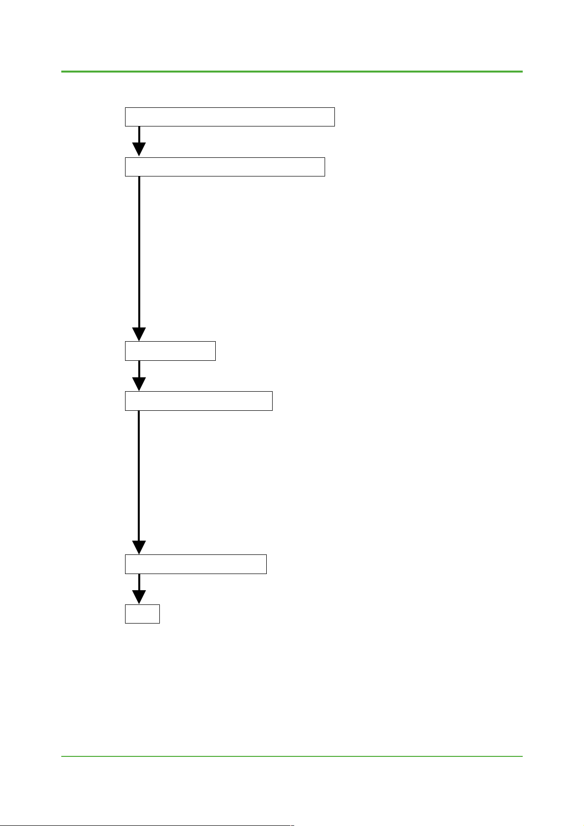
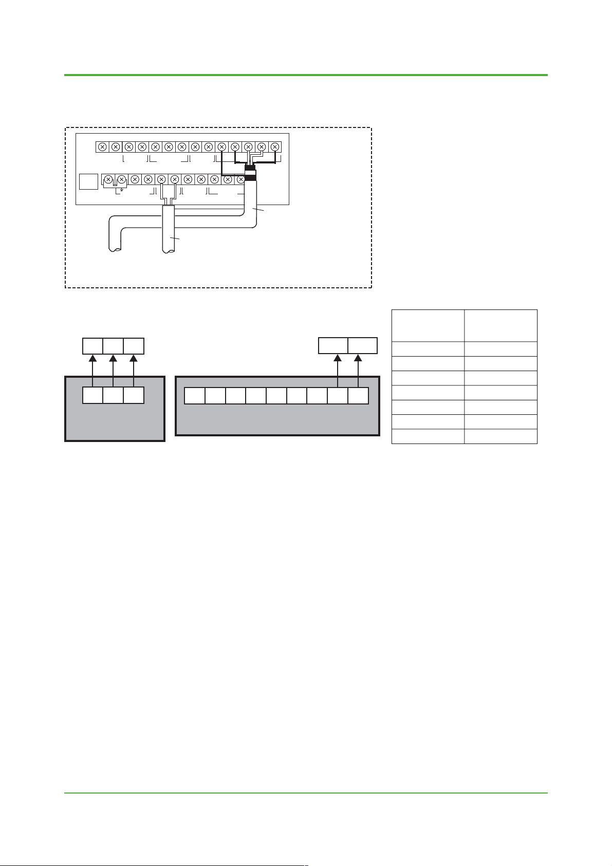
4.2 How to Obtain Meter Factor b y Incorporating the Indicated Flow Rate of the Existing Con verter .
This method can be used if an existing flowtube operates properly. In addition, the method
requires that the flow rate is constant and stable. In case of this method, the accuracy for reference cannot be provided as it depends on the accuracy of the measuring flow system. As a rule,
calibration should be performed by Y okoga wa service personnel.
Electrical connection:
Connect an existing flowtube and an e xisting conv erter as shown in the figure below:
18
Existing converter
Excitation cable
Change electrical connections
Signal cable
AXFA11
Flowtube
4.2.1 Parameter setting
Set the size and span to AXFA11. The span shall be the same as the one for the
existing converter. In addition, set the parameters according to any combination with
relevant models in Chapter 2. For "C21: Low MF," set 1.0000 at first temporarily.
4.2.2 Zero adjustment
Before allowing the fluid to flow, see the user's manual for AXFA11 and perform the
automatic zero adjustment. Also apply the zero adjustment to the existing converter.
4.2.3 Measuring flow with existing con verter
Measure an instantaneous flow rate in the combination with the existing converter
and record the 4 to 20 mA output. Since the indication of AXFA11 at the same flow
rate is checked in the next step, do not change the flow rate.
4 to 20 mA
Recorder
4 to 20 mA
F04.EPS
4.2.4 Measuring flow with AXFA11 converter
Change the connections of the existing flowtube to AXFA11 and record the 4 to w20
mA output in the same manner.
4.2.5 Calculating the meter factor
Use the indicated value of the existing converter and the indicated value of AXFA11,
which were recorded in the above step, and calculate the new meter factor as
follows:
New meter factor = old meter factor ⫻
Use 1.0000, which was temporarily set to the old meter factor, to calculate the new
meter factor. After setting the new meter factor, confirm that the flow indication is
correct. If the flow indication is not correct, repeat the above procedure and incorporate the new meter factor.
All Rights Reserved. Copyright © 2004, Yokogawa Electric Corporation
Indicated value of AXFA11 (%)
Indicated value of the existing converter (%)
TI 01E20A02-01E 2004-00
Page 19

<T oc> <Ind>
4.3 How to Obtain Meter Factor Accor ding to the Inferred Flow Rates Such as Valve Openings or Pump Rpm
The accuracy for ref erence in this case cannot be provided as it depends on the accur acy of the
inferred flow rate . As a rule, calibr ation should be performed by Yokogawa's service personnel.
4.3.1 Parameter setting
Set the size and span to AXFA11. The span shall be 1.5 to 2 times the flow rate. In
addition, set necessary parameters according to any combination with relevant
models in Chapter 2. For "C21: Low MF," set 1.0000 at first temporarily.
4.3.2 Zero adjustment
Before allowing the fluid to flow, see the user's manual for AXFA11 and perform the
automatic zero adjustment.
4.3.3 Measuring flow and calculating the meter factor
Allow the fluid to flow and calculate the new meter factor as follows:
19
New meter factor = old meter factor ⫻
Use 1.0000, which was temporarily set to the old meter factor, to calculate the new
meter factor. After setting the new meter factor, confirm that the flow indication is
correct. If the flow indication is not correct, repeat the above procedure and incorporate the new meter factor.
Indicated value of AXFA11
Inferred flow rate
All Rights Reserved. Copyright © 2004, Yokogawa Electric Corporation TI 01E20A02-01E
2004-00
Page 20

<T oc> <Ind>
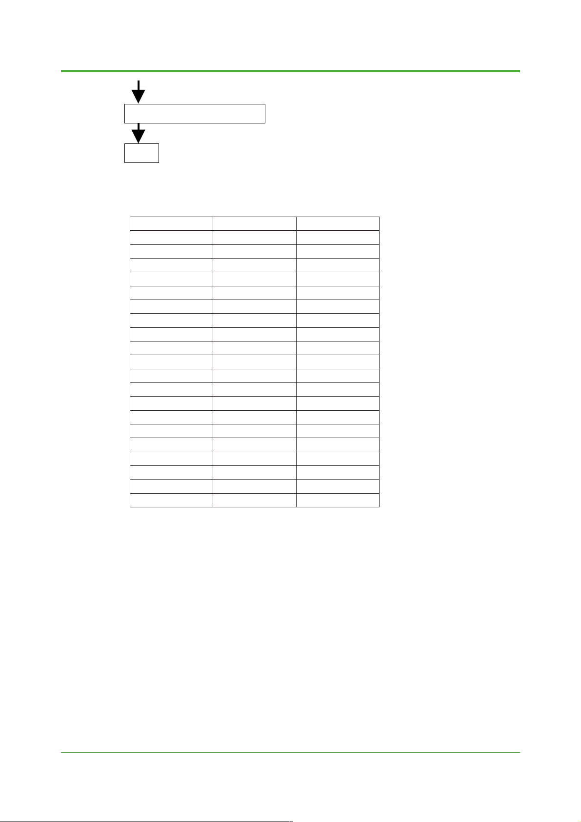
5. Compatibility with AXF A11 and AXFA14
If the same AXF flowtube is combined with AXF A11 or AXFA14, meter factors will differ due to
differences between the excitation circuit of AXFA11 and that of AXFA14. Therefore, wrong
combinations will cause a span error. A span error for reference is approximately 1.5%. Select the
correct converter for combination using the flowtube's model and suffix code when ordering.
Since AXF A14 does not hav e a parameter f or setting the e xcitation current v alue or s witching to
the pulsed DC calculation, AXF A14 cannot operate SE, YM and flowtubes of other manufactures.
AXF A14 can only operate AXF, AM and AE flowtubes.
On the other hanwd, as AXF A11 has a parameter “C30:Select Flo w tube” for setting the e xcitation
current value or switching to the pulsed DC calculation, AXFA11 can operate other flowtubes
including SE and YM.
Compatibility errors for AXFA11 and AXFA14 if flow calibration is not redone (v alues for
reference)
Converter
Flowtube
AXF flowtube
for AXFA11
(AXFxxxx-N)
AXF flowtube
for AXFA14
(AXFxxxx-P)
AM flowtube
AE flowtube
SE flowtube
AXFA11
AXF std.
performance
accuracy
AXF std. accuracy
⫾1.5%
AM std. accuracy
⫾0.5%
AE std. accuracy
⫾1.5%
not available
unless redoing
flow calibration
YM std. accuracy
⫾1% when
calculated MF is
used
AXFA14
AXF std. accuracy
⫾1.5%
AXF std.
performance
accuracy
AM std. accuracy
⫾1.5%
AE std. accuracy
⫾0.5%
not available
AM11
AM std. accuracy
⫾0.5%
AM std. accuracy
⫾1.5%
AM std.
performance
accuracy
AE std. accuracy
⫾1.5%
not available
See TI 1E6C1-01E not availablenot available not availableYM flowtube
AE std. accuracy
⫾1.5%
AE std. accuracy
⫾0.5%
AE std. accuracy
⫾1.5%
(in principle, not
available)
AE std.
performance
accuracy
not available
not available
not available
not available
not available
performance
accuracy
20
YMA11AE14 SE14
YM std. accuracy
⫾2% when
calculated MF is
used.
not available
unless redoing
flow calibration
See TI 1E6C1-01E
not available
SE std.
not available
YM std.
performance
accuracy
T07.EPS
All Rights Reserved. Copyright © 2004, Yokogawa Electric Corporation
TI 01E20A02-01E 2004-00
Page 21

<T oc> <Ind>
Appendix. 1 Electrical Connection
CAUTION
1. Disconnect ac power the magmeter flowtube.
Flowtube will be powered by the Yokogawa converter.
2. Follow the proper Y okoga wa wiring procedure f or the make and model of magnetic flo wtube
being converted. f ailure to f ollow the proper wiring procedure will result in damage to the
Yokogawa converter .
21
All Rights Reserved. Copyright © 2004, Yokogawa Electric Corporation TI 01E20A02-01E
2004-00
Page 22

<T oc> <Ind>
(1) Combination AXFA11 and FO XBOR O 1800 Series
22
AXFA11 Wiring Connections
FUSE
2.5A 250V
I+ I–
CURRENT OUT
N/– L/+
POWER SUPPLY
SO1+ COMSO2+
STATUS OUT
EXCIT ATION
AL+ AL– C SA A B SB
ALARM OUT
EX2EX1
PULSE OUT STATUS IN
Excitation cable
AM011 or YM011 Dedicated signal cable
can be used unless those cables are
deteriorated.
FOXBORO 1800 Wiring
Sample A
To AXFA11 Excitation Terminals
Terminal correspondences
Converter
AXFA11
SIGNAL
P– SI1+ SI2+ COMP+
AXFA11 Converter
SA *
SB *
A
1
1
B
AXFC Dedicated signal
cable
C
EX1 *
EX2 *
2
2
Flowtube
1800 Series
Taped
Taped
B
W
SH
L1
L2
*1 When a shield drive is not caried out,
SA and SB marked are not used.
*2 If we read negative output, exchange
EX1 and EX2 at AXFA11 terminal.
*3 Exciting power coils must be isolated
from ground and other all terminals.
Excitation Power Coil Wiring
Excitation Power Terminals
Sample B
To AXFA11 Excitation Terminals
Excitation Power Terminals
WB
W
G
To AXFA11 Signal Terminals
Signal T erminals
To AXFA11 Signal Terminals
OUT
Signal T erminals
BG
B
SH
Series Wiring Parallel Wiring
Excitation Power Coil Wiring
SH
Series Wiring Parallel Wiring
AF02.EPS
All Rights Reserved. Copyright © 2004, Yokogawa Electric Corporation
TI 01E20A02-01E
2004-00
Page 23

<T oc> <Ind>
23
FOXBOR O 1800 Series Meter Factor List
Following are model numbers , Exciting current values and appro ximate meter f actors f or
flowtubes where the coils are wired either in series or parallel.
Nominal Size Series Connection
LOW MF (C21)
15
25
40
50
80
100
150
200
250
300
350
400
0.5
1
1.5
2
3
4
6
8
10
12
14
16
0.4483
0.4852
0.5852
0.5518
0.6150
0.4609
0.4167
0.3500
0.3990
0.2727
0.3274
0.6373
Parallel Connection
LOW MF (C21)mm inch
0.2241
0.2426
0.2926
0.2765
0.3075
0.2304
0.2083
0.1705
0.1995
0.1363
0.1316
0.3183
For FOXBORO 1800 Series
AF03.EPS
All Rights Reserved. Copyright © 2004, Yokogawa Electric Corporation TI 01E20A02-01E
2004-00
Page 24

<T oc> <Ind>
(2) Combination AXFA11 and FO XBOR O 2800 Series
24
AXFA11 Wiring Connections
FUSE
2.5A 250V
I+ I–
CURRENT OUT
N/– L/+
POWER SUPPLY
SO1+ COMSO2+
STATU S OU T
EXCIT ATION
AL+ AL– C SA A B SB
ALARM OUT
EX2EX1
PULSE OUT STATUS IN
Excitation cable
AM011 or YM011 Dedicated signal cable
can be used unless those cables are
deteriorated.
FOXBORO 2800 Wiring
Terminal correspondences
Converter
AXFA11
SIGNAL
AXFA11 Converter
SA
SB
P– SI1+ SI2+ COMP+
A
B
AXFC Dedicated signal
cable
C
EX1 *
EX2 *
Flowmeter
2800 Series
BG
WG
B
W
SH
L1
L2
* If we read negative output, exchange
EX1 and EX2 at AXFA11 terminals.
Excitation Power Coil Wiring
WG
Excitation Power Terminals
W
BG
B
SH
G
Signal T erminals
To AXFA11 Signal Terminals
To AXFA11 Excitation Terminals
Series Wiring
Parallel Wiring
AF04.EPS
All Rights Reserved. Copyright © 2004, Yokogawa Electric Corporation
TI 01E20A02-01E
2004-00
Page 25
<T oc> <Ind>
25
FOXBOR O 2800 Series Meter Factor List
Following are model numbers , Excitation current values and appro ximate meter f actors f or
flowtubes where the coils are wired either in series or parallel.
Model
2891
2893
2893
280H
2801
2801
281H
281H
2802
2802
2802
2802
2803
2803
2803
2803
2804
2804
2804
2804
2806
2806
2806
2806
2808
2808
2808
2810
2810
2810
2812
2812
2812
Liner
TF
TF
TF
TF
TF
TT
TF
TT
TF
TT
CR
UL
TF
TT
CR
UL
TF
TT
CR
UL
TF
TT
CR
UL
TF
CR
UL
TF
CR
UL
TF
CR
UL
Nominal Size Series Connection
LOW MF (C21)
2.5
5.1
9.5
15
25
25
40
40
50
50
50
50
80
80
80
80
100
100
100
100
150
150
150
150
200
200
200
250
250
250
300
300
300
0.1
0.2
0.375
0.5
1
1
1.5
1.5
2
2
2
2
3
3
3
3
4
4
4
4
6
6
6
6
8
8
8
10
10
10
12
12
12
0.2229
0.2922
0.4280
0.4854
0.5767
0.9939
0.7500
1.0690
0.7630
0.9852
0.8593
1.0370
0.8992
1.0310
0.9612
1.1630
0.7823
0.8686
0.7823
0.9921
0.5139
0.5421
0.5275
0.6045
0.4269
0.4267
0.4731
0.6316
0.6322
0.6704
0.5018
0.5023
0.5272
Parallel Connection
LOW MF (C21)mm inch
—
—
—
0.2426
0.2883
0.4649
0.3750
0.5374
0.3814
0.4925
0.4296
0.5185
0.4496
0.5115
0.4806
0.5813
0.3911
0.4342
0.3911
0.4960
0.2569
0.2710
0.2637
0.3022
0.2134
0.2138
0.2365
0.3158
0.3158
0.3352
0.2509
0.2511
0.2635
AF05.EPS
All Rights Reserved. Copyright © 2004, Yokogawa Electric Corporation TI 01E20A02-01E
2004-00
Page 26

<T oc> <Ind>
(3) Combination AXFA11 and F&P 10D1418 Series
AXFA11 Wiring Connections
26
AXFA11 Converter
FUSE
2.5A 250V
I+ I–
CURRENT OUT
N/– L/+
POWER SUPPLY
SO1+ COMSO2+
STATU S OU T
EXCIT ATION
AL+ AL– C SA A B SB
ALARM OUT
EX2EX1
P– SI1+ SI2+ COMP+
PULSE OUT STATUS IN
SIGNAL
AXFC Dedicated signal
cable
Excitation cable
AM011 or YM011 Dedicated signal cable
can be used unless those cables are
deteriorated.
F&P 10D1418 (Internal Phase) Wiring (1/10” to 4”)
To AXFA11 Signal Terminals
ABC
Phasing TB
123
Meter
Pipe
8L2L1 567
Signal Compartment
Terminal correspondences
(Integral phase)
Converter
AXFA11
1
SA *
2
SB *
A
B
C
2
EX1 *
2
EX2 *
F&P 10D1418
AC-MAG
Taped
Taped
1
2
3
L1
L2
*1 When a shield drive is not caried out,
SA and SB marked are not used.
*2 If we read negative output, exchange
EX1 and EX2 at AXFA11 terminal.
*3 Exciting power coils must be isolated
from ground and other all terminals.
Disconnection
L1 L2G5876
Power Compartment
EX1 EX2
To AXFA11 Excitation Terminals
All Rights Reserved. Copyright © 2004, Yokogawa Electric Corporation
Phasing Network (No Use)
TI 01E20A02-01E
AF06.EPS
2004-00
Page 27

<T oc> <Ind>
F&P 10D1418 (Remote Phase) Wiring (1/10” to 4”)
To AXFA11 Signal Terminals
ABC
123
Meter
Pipe
Signal Compartment
Terminal correspondences
(Remote phase)
Converter
AXFA11
1
SA *
2
SB *
A
B
C
2
EX1 *
2
EX2 *
*1 When a shield drive is not caried out,
SA and SB marked are not used.
*2 If we read negative output, exchange
EX1 and EX2 at AXFA11 terminal.
*3 Exciting power coils must be isolated
from ground and other all terminals.
F&P 10D1418
AC-MAG
Taped
Taped
1
2
3
L1
8
27
U2 5L1U1 G 76L2 8
Power Compartment
EX1 EX2
To AXFA11 Excitation Terminals
MODIFICATION
1) Disconnect AC-Power Supply from flowtube, and connect Excitation Cable from AXFA11 to flowtube Terminal
(Power Compartment T B L1, 8)
2) Connect Signal Cable from AXFA11 to flowtube. Be sure that No. 3 Terminal of Signal Compartment is definitely
grounded to the Mag Body.
AF07.EPS
All Rights Reserved. Copyright © 2004, Yokogawa Electric Corporation TI 01E20A02-01E
2004-00
Page 28

<T oc> <Ind>
(4) Combination AXFA11 and F&P 10D1419 Series
AXFA11 Wiring Connections
28
FUSE
2.5A 250V
I+ I–
CURRENT OUT
N/– L/+
POWER SUPPLY
SO1+ COMSO2+
STATUS OUT
EXCIT ATION
AL+ AL– C SA A B SB
ALARM OUT
EX2EX1
P– SI1+ SI2+ COMP+
PULSE OUT STATUS IN
SIGNAL
AXFC Dedicated signal
cable
Excitation cable
AM011 or YM011 Dedicated signal cable
can be used unless those cables are
deteriorated.
F&P 10D1419 (Integral) Wiring (1/10” to 4”)
To AXFA11 Signal TerminalsTo AXFA11 Excitation Terminals
EX1 EX2
BA C
18L1 17L2 1 3216
TB
MODIFICATION
Disconnect L1, L2, M1, M2 of magnet driver ass’y. Connect L1
and M1 at air, also connect L2 and M2 at air. (Do not Connect
these wires at terminals)
AXFA11 Converter
Terminal correspondences
Converter
AXFA11
1
SA *
1
SB *
A
B
C
2
EX1 *
2
EX2 *
F&P 10D1419
AC-MAG
Taped
Taped
1
2
3
L1
L2
*1 When a shield drive is not caried out,
SA and SB marked are not used.
*2 If we read negative output, exchange
EX1 and EX2 at AXFA11 terminal.
*3 Exciting power coils must be isolated
from ground and other all terminals.
F&P 10D1419 (Remote Type) Wiring
To AXFA11 Excitation Terminals
EX1 EX2
To AXFA11 Signal Terminals
BA C
M1L1 M2L2 1 325
TB
All Rights Reserved. Copyright © 2004, Yokogawa Electric Corporation
Terminal correspondences
Converter
AXFA11
1
SA *
1
SB *
A
B
C
2
EX1 *
2
EX2 *
F&P 10D1419
AC-MAG
Taped
Taped
1
2
3
M1
M2
*1 When a shield drive is not caried out,
SA and SB marked are not used.
*2 If we read negative output, exchange
EX1 and EX2 at AXFA11 terminal.
*3 Exciting power coils must be isolated
from ground and other all terminals.
AF08.EPS
TI 01E20A02-01E
2004-00
Page 29

<T oc> <Ind>
(5) Combination AXFA11 and F&P 10D1430 Series
AXFA11 Wiring Connections
29
FUSE
2.5A 250V
I+ I–
CURRENT OUT
N/– L/+
POWER SUPPLY
SO1+ COMSO2+
STATU S OU T
EXCIT ATION
AL+ AL– C SA A B SB
ALARM OUT
EX2EX1
P– SI1+ SI2+ COMP+
PULSE OUT STATUS IN
SIGNAL
AXFC Dedicated signal
cable
Excitation cable
AM011 or YM011 Dedicated signal cable
can be used unless those cables are
deteriorated.
F&P 10D1430 (Integral Phasing Type) Wiring
To AXFA11 Signal Terminals
BA C
TB1
TB2
37216U1L1 U2L2
To AXFA11 Excitation Terminals
EX1 EX2
7G2613 U2U1L2
L1
8
Disconnection
AXFA11 Converter
Interconnection
Terminal correspondences
Converter
AXFA11
1
SA *
1
SB *
A
B
C
2
EX1 *
2
EX2 *
F&P 10D1430
Taped
Taped
1
2
3
L1
L2
*1 When a shield drive is not caried out,
SA and SB marked are not used.
*2 If we read negative output, exchange
EX1 and EX2 at AXFA11 terminal.
*3 Exciting power coils must be isolated
from ground and other all terminals.
Calibration components
MODIFICATION
1) Remove L2 at TB2 (FM TB) and connect No. 8 terminal of TB2.
2) Disconnect No. 8 terminal of TB2 (Wire from calibration components) and tape it.
All Rights Reserved. Copyright © 2004, Yokogawa Electric Corporation TI 01E20A02-01E
AF09.EPS
2004-00
Page 30

<T oc> <Ind>
F&P 10D1430 (Remote Cali. Type) Wiring
To AXFA11 Signal Terminals
BA C
Signal Junction Box
1) Disconnect power wires L1, 8 at Power junction box, and
connect AXFA11's excitation cable to these L1, 8 terminal.
Disconnect power
wires from calib.
MODIFICATION
To AXFA11 Excitation Terminals
EX2 EX1
Power Junction Box
30
Terminal correspondences
Converter
AXFA11
1
SA *
1
SB *
A
8G L1123
*1 When a shield drive is not caried out,
*2 If we read negative output, exchange
*3 Exciting power coils must be isolated
B
C
2
EX1 *
2
EX2 *
SA and SB marked are not used.
EX1 and EX2 at AXFA11 terminal.
from ground and other all terminals.
F&P 10D1430
Taped
Taped
1
2
3
L1
8
F&P 10D1430 (Submersible Type) Wiring
To AXFA11 Signal Terminals
BA C
213T1T3T2 T4
8L2 6L1 7 U2 GU1
Remote Phasing Box
Disconnection
EX1 EX2
To AXFA11 Excitation Terminals
Meter
Pipe
Terminal correspondences
Converter
AXFA11
1
SA *
1
SB *
A
B
C
2
EX1 *
2
EX2 *
*1 When a shield drive is not caried out,
SA and SB marked are not used.
*2 If we read negative output, exchange
EX1 and EX2 at AXFA11 terminal.
*3 Exciting power coils must be isolated
from ground and other all terminals.
F&P 10D1430
Taped
Taped
1
2
3
L1
8
MODIFICATION
1) Disconnect power wires L1, 8 at remote box, and connect
AXFA11's excitation cable to L1, 8 air.
All Rights Reserved. Copyright © 2004, Yokogawa Electric Corporation
TI 01E20A02-01E
AF10.EPS
2004-00
Page 31

<T oc> <Ind>
(6) Combination AXFA11 and F&P 10D1435 (MAGX) Series (6” to 48”)
AXFA11 Wiring Connections
31
FUSE
2.5A 250V
I+ I–
CURRENT OUT
N/– L/+
POWER SUPPLY
SO1+ COMSO2+
STATU S OU T
EXCIT ATION
AL+ AL– C SA A B SB
ALARM OUT
EX2EX1
P– SI1+ SI2+ COMP+
PULSE OUT STATUS IN
SIGNAL
AXFC Dedicated signal
cable
Excitation cable
AM011 or YM011 Dedicated signal cable
can be used unless those cables are
deteriorated.
F&P 10D1435 (Integral Magnet Driver) Wiring
To AXFA11 Signal Terminals
BA C
TB1
18 17316 M2 L1GM1
163G12 17 U118 GU2L1
TB2
L2
L2
TB3
Ex. Coil
EX1 EX2
To AXFA11 Excitation Terminals
AXFA11 Converter
Terminal correspondences
Converter
AXFA11
1
SA *
1
SB *
A
B
C
2
EX1 *
2
EX2 *
F&P 10D1435
MAGX
Taped
Taped
1
2
3
Ex. Coil
Ex. Coil
*1 When a shield drive is not caried out,
SA and SB marked are not used.
*2 If we read negative output, exchange
EX1 and EX2 at AXFA11 terminal.
*3 Exciting power coils must be isolated
from ground and other all terminals.
MODIFICATION
Disconnect Ex. Coil Wires from M1, M2 and Connect Ex1 and
Ex2 cable from AXFA11 at air.
Terminal correspondences
F&P 10D1435 (Remote Magnet Driver) Wiring
To AXFA11 Excitation Terminals
EX1 EX2
Mgnet Driver
Converter
AXFA11
1
SA *
1
SB *
A
F&P 10D1435
B
L2 M2L1GM117163
3L2L1G12T2T1T3T4
18
C
2
EX1 *
2
EX2 *
*1 When a shield drive is not caried out,
SA and SB marked are not used.
Remote Driver
BC A
To AXFA11 Signal Terminals
All Rights Reserved. Copyright © 2004, Yokogawa Electric Corporation TI 01E20A02-01E
*2 If we read negative output, exchange
EX1 and EX2 at AXFA11 terminal.
*3 Exciting power coils must be isolated
from ground and other all terminals.
MAGX
Taped
Taped
1
2
3
M1
M2
AF11.EPS
2004-00
Page 32

<T oc> <Ind>
(7) Combination AXFA11 and F&P 10D1475 (MINI MAGX) Series
AXFA11 Wiring Connections
32
FUSE
2.5A 250V
I+ I–
CURRENT OUT
N/– L/+
POWER SUPPLY
SO1+ COMSO2+
STATU S OU T
EXCIT ATION
AL+ AL– C SA A B SB
ALARM OUT
EX2EX1
P– SI1+ SI2+ COMP+
PULSE OUT STATUS IN
SIGNAL
AXFC Dedicated signal
cable
Excitation cable
AM011 or YM011 Dedicated signal cable
can be used unless those cables are
deteriorated.
F&P 10D1475 (Integral Type) Wiring
To AXFA11 Signal Terminals
AB C
To AXFA11 Excitation Terminals
EX1 EX2
2A 12MR536M1M2CT
(Ground Terminal)
MODIFICATION
1) Disconnect all wires from this terminal except signal and
exciting wires as shown.
AXFA11 Converter
Terminal correspondences
Converter
AXFA11
1
SA *
1
SB *
A
B
C
2
EX1 *
2
EX2 *
F&P 10D1475
MINI-MAG
Taped
Taped
1
2
Ground
M1
MR
*1 When a shield drive is not caried out,
SA and SB marked are not used.
*2 If we read negative output, exchange
EX1 and EX2 at AXFA11 terminal.
*3 Exciting power coils must be isolated
from ground and other all terminals.
F&P 10D1475C (Remote Type) Wiring
To AXFA11 Signal Terminals
BA C
To AXFA11 Excitation Terminals
EX1 EX2
M1 M2V⫺V⫹ 11632
CT MRMRM2 M1 M1
MODIFICATION
1) Disconnect M1, M2 of primary board and connect another
M1, MR.
All Rights Reserved. Copyright © 2004, Yokogawa Electric Corporation
Terminal correspondences
Converter
AXFA11
1
SA *
1
SB *
A
B
C
2
EX1 *
2
EX2 *
F&P 10D1475
MINI-MAG
Taped
Taped
1
2
3
M1
M2
*1 When a shield drive is not caried out,
SA and SB marked are not used.
*2 If we read negative output, exchange
EX1 and EX2 at AXFA11 terminal.
*3 Exciting power coils must be isolated
from ground and other all terminals.
AF12.EPS
TI 01E20A02-01E
2004-00
Page 33

<T oc> <Ind>
(8) Combination AXFA11 and BR OOKS 7000 Series
AXFA11 Wiring Connections
33
SO1+ COMSO2+
I+ I–
FUSE
2.5A 250V
CURRENT OUT
POWER SUPPLY
N/– L/+
STATU S OU T
EXCIT ATION
BROOKS 7000 Wiring
To AXFA11 Signal Terminals
A B C
E1 E3
To Mag Flowtube
E2
AL+ AL– C SA A B SB
ALARM OUT
EX2EX1
P– SI1+ SI2+ COMP+
PULSE OUT STATUS IN
SIGNAL
AXFC Dedicated signal
cable
Excitation cable
AM011 or YM011 Dedicated signal cable
can be used unless those cables are
deteriorated.
To AXFA11 Excitation Terminals
EX1 EX2
11 12
Amplifier board
To Mag Flowtube
Do not leave the wires (black,
white, No.11, 12) inthe terminal
AXFA11 Converter
TB-02
Terminal correspondences
Converter
AXFA11
1
SA *
1
SB *
A
B
C
2
EX1 *
2
EX2 *
BROOKS
7000 Series
Taped
Taped
E1 of AMP.
E3 of AMP.
E2 of AMP.
11 of TB-02.
12 of TB-02.
*1 When a shield drive is not caried out,
SA and SB marked are not used.
*2 If we read negative output, exchange
EX1 and EX2 at AXFA11 terminal.
*3 Exciting power coils must be isolated
from ground and other all terminals.
MODIFICATION
1) Disconnect power supply at L1 DG TB4-AC power and J2, J5 in Mag flowtube. (No power supply needs to Brooks Mag)
2) Remove wires of TB-11 and 12 in power supply board and connect EX1, EX2 (AXFA11) to these wires as follows:
EX1 EX2=Excitation Power from AXFA11
AXFA11
EX1
EX2
7000 TB-02
11
12
Do not connect these wires at
terminals, connect at air
3) Remove E1, E2, E3 of amplifier board and connect A, B and C
AXFA11
EX1 EX2=Signal terminal from AXFA11
A
B
C
All Rights Reserved. Copyright © 2004, Yokogawa Electric Corporation TI 01E20A02-01E
7000 TB-02
E1
E3
E2
Do not connect these wires at
terminals, connect at air
AF13.EPS
2004-00
Page 34

<T oc> <Ind>
(9) Combination AXFA11 and BR OOKS 7100 Series
AXFA11 Wiring Connections
34
SO1+ COMSO2+
I+ I–
FUSE
2.5A 250V
CURRENT OUT
POWER SUPPLY
N/– L/+
STATUS OUT
EXCIT ATION
BROOKS 7100 Wiring
To AXFA11 Signal Terminals
C
BA
ACB
To Pre Amp. Area
AL+ AL– C SA A B SB
ALARM OUT
EX2EX1
P– SI1+ SI2+ COMP+
PULSE OUT STATUS IN
SIGNAL
AXFC Dedicated signal
cable
Excitation cable
AM011 or YM011 Dedicated signal cable
can be used unless those cables are
deteriorated.
To AXFA11 Excitation Terminals
EX1 EX2
L
LG
TB-2
Junction box on top of flowtube
AXFA11 Converter
TB-4
Terminal correspondences
Converter
AXFA11
1
SA *
1
SB *
A
B
C
2
EX1 *
2
EX2 *
BROOKS
7100 Series
AC-MAG
Taped
Taped
A (TB2)
C (TB2)
B (TB2)
L (TB4)
LG (TB4)
*1 When a shield drive is not caried out,
SA and SB marked are not used.
*2 If we read negative output, exchange
EX1 and EX2 at AXFA11 terminal.
*3 Exciting power coils must be isolated
from ground and other all terminals.
All Rights Reserved. Copyright © 2004, Yokogawa Electric Corporation
TI 01E20A02-01E
AF14.EPS
2004-00
Page 35
<T oc> <Ind>
(10) Combination AXF A11 and BROOKS 7400 Series
AXFA11 Wiring Connections
35
I+ I–
SO1+ COMSO2+
FUSE
2.5A 250V
CURRENT OUT
POWER SUPPLY
N/– L/+
STATU S OU T
EXCIT ATION
BROOKS 7400 Wiring
To AXFA11 Signal Terminals
CA
B
123
TB-1
AL+ AL– C SA A B SB
ALARM OUT
EX2EX1
P– SI1+ SI2+ COMP+
PULSE OUT STATUS IN
SIGNAL
AXFC Dedicated signal
cable
Excitation cable
AM011 or YM011 Dedicated signal cable
can be used unless those cables are
deteriorated.
To AXFA11 Excitation Terminals
324168957
TB-4
AXFA11 Converter
EX1 EX2
Terminal correspondences
Converter
AXFA11
1
SA *
1
SB *
A
B
C
2
EX1 *
2
EX2 *
BROOKS
7400 Series
Wafer-MAG
Taped
Taped
2 (TB1)
3 (TB1)
1 (TB1)
8 (TB2)
9 (TB2)
*1 When a shield drive is not caried out,
SA and SB marked are not used.
*2 If we read negative output, exchange
EX1 and EX2 at AXFA11 terminal.
*3 Exciting power coils must be isolated
from ground and other all terminals.
Brooks 7400 Wafer Mag
It is necessary to modify following terminal and connectors.
1) Signal Cable Connector J1
2) Field Coil Connector J3
3) Customer Hook-up TB1, TB2
How to Modify BROOKS 7400 Wafer Mag
1) Open Electronic Box Cover.
2) Remove whole electronics from electronics box.
3) Disconnect all wires from TB1, TB2, except No. One Terminal of TB1.
4) Modification of J3 (Field Coil)
Connect No.2, No.5 wires of J3 Connector (Field Coil Connector) to Terminal 8, 9 of TB2.
Connect No.1, No.6 wires of J3 at air. (To make a closed loop of an excitation circuit)
5) J1 (Signal Cable)
Connect No.2, No.3 wires at air.
Also connect No.4, No.1 wires to No.2 and No.3 Terminal of TB1.
6) Connect cables from AXFA11 to Wafer-Mag customer hook-up.
All Rights Reserved. Copyright © 2004, Yokogawa Electric Corporation TI 01E20A02-01E
AF15.EPS
2004-00
Page 36

<T oc> <Ind>
(11) Combination AXF A11 and BROOKS 7500 Series
AXFA11 Wiring Connections
36
I+ I–
SO1+ COMSO2+
FUSE
2.5A 250V
CURRENT OUT
POWER SUPPLY
N/– L/+
STATUS OUT
EXCIT ATION
BROOKS 7500 Wiring
To AXFA11
Excitation
Terminals
EX2
EX1
5
2
J3
AL+ AL– C SA A B SB
ALARM OUT
EX2EX1
P– SI1+ SI2+ COMP+
PULSE OUT STATUS IN
SIGNAL
AXFC Dedicated signal
cable
Excitation cable
AM011 or YM011 Dedicated signal cable
can be used unless those cables are
deteriorated.
4
J4
Left
Electrode
J1
Top Coil
Right Electrode
Bottom Coil
AXFA11 Converter
To AXFA11
Signal
Terminals
1
B
A
Terminal correspondences
Converter
AXFA11
1
SA *
1
SB *
A
B
C
2
EX1 *
2
EX2 *
BROOKS
7500 Series
Taped
Taped
1 of J1
4 of J1
System Com
2 of J3
5 of J3
*1 When a shield drive is not caried out,
SA and SB marked are not used.
*2 If we read negative output, exchange
EX1 and EX2 at AXFA11 terminal.
*3 Exciting power coils must be isolated
from ground and other all terminals.
How to Combination AXFA11 and BROOKS 7500
1) Power disconnection of flowtube
Disconnect power supply (L, N) at TB1 in customer hook-up. (No power supply needs to BROOKS 7500 Mag.)
2) Excitation power from AXFA11 to flowtube.
Cut wires of connector J3 (Female side) on power supply coil drive.
Connect EX1, EX2 (From AXFA11) to these wires as follows:
AXFA11
EX1
EX2
7500 J3/Power
Coil Drive
2
5
Do not connect these wires at
terminals, connect at air
3) Signal wiring to AXFA11
Cut wires of connecter (J1, Female) on signal conditioner.
Connect A, B and C to these wires as follows:
AXFA11
All Rights Reserved. Copyright © 2004, Yokogawa Electric Corporation
7500 J3/Power Coil Drive
A
B
C
System Com. at signal
Cond. (2, 3) Maile side
1
4
Do not connect these wires at
terminals, connect at air
TI 01E20A02-01E
AF16.EPS
2004-00
Page 37

<T oc> <Ind>
(12) Combination AXF A11 and KROHNE ALTFLUX X-1000, M900 Series
AXFA11 Wiring Connections
37
AXFA11 Converter
FUSE
2.5A 250V
I+ I–
CURRENT OUT
N/– L/+
POWER SUPPLY
SO1+ COMSO2+
STATU S OU T
EXCIT ATION
AL+ AL– C SA A B SB
ALARM OUT
EX2EX1
P– SI1+ SI2+ COMP+
PULSE OUT STATUS IN
SIGNAL
AXFC Dedicated signal
cable
Excitation cable
AM011 or YM011 Dedicated signal cable
can be used unless those cables are
deteriorated.
X-1000, M900 Series (Using Signal Cable Type A) Wiring
To AXFA11 Signal Terminals To AXFA11 Excitation Terminals
C
AB
EX1 EX2
32120 30 1112789
T900
21 3
M900, X-1000
7
8
Disconnection
Terminal correspondences
Converter
AXFA11
1
SA *
1
SB *
A
B
C
2
EX1 *
2
EX2 *
L1
N
*1 When a shield drive is not caried out,
SA and SB marked are not used.
KROHNE
ALTFLUX
Taped
Taped
2
3
1
7
8
*2 If we read negative output, exchange
EX1 and EX2 at AXFA11 terminal.
*3 Exciting power coils must be isolated
from ground and other all terminals.
X-1000, M900 Series (Using Signal Cable Type B) Wiring
To AXFA11 Signal Terminals To AXFA11 Excitation Terminals
SACABSB
EX1 EX2
Terminal correspondences
Converter
AXFA11
1
SA *
1
SB *
A
32120 30 1112789
B
C
EX1
EX2
SA and SB marked are not used.
21 3
T900
L1
N
7
8
Disconnection
*1 When a shield drive is not caried out,
M900, X-1000
All Rights Reserved. Copyright © 2004, Yokogawa Electric Corporation TI 01E20A02-01E
KROHNE
ALTFLUX
20
30
2
3
1
7
8
AF17.EPS
2004-00
Page 38

<T oc> <Ind>
How to Combination AXF A11 and KR OHNE ALTFLUX X-1000, AL TFLUX MT900 Series
1. Signal Wiring from Flowtube to AXFA11
Disconnect all signal wires from T900F signal terminals (No .1, 20, 2, 3, 30).
Connect these wires to AXF A11 signal terminals as below . Please do not connect these
wires at T900F signal terminals; but, connect at AXFA11 signal terminals .
AXFA11 Signal terminals X-1000 / M900 Signal Wires
A
B
C
SA
SB
2 (Common)
3 (Common)
1 (Common)
Shield for 20
Shield for 30
AF18-1.EPS
2. Excitation Pow er from AXFA11 to Flowtube
Disconnect wires from terminals No. 7, 8 of T900F.
Connect wires to EX1, EX2 or AXF A11 as shown belo w .
AXFA11 X-1000 / M900
EX1
EX2
7
8
AF18-2.EPS
38
If we need a negative output, exchange EX1 and EX2.
All Rights Reserved. Copyright © 2004, Yokogawa Electric Corporation
TI 01E20A02-01E
2004-00
Page 39

<T oc> <Ind>
(13) Combination AXF A11 and ROSEMOUNT 8701
AXFA11 Wiring Connections
39
SO1+ COMSO2+
I+ I–
CURRENT OUT
FUSE
2.5A 250V
N/– L/+
POWER SUPPLY
Model 8701 Wiring
To AXFA11 Excitation Terminals
To AXFA11 Signal Terminals
STATU S OU T
EXCIT ATION
AL+ AL– C SA A B SB
ALARM OUT
EX2EX1
PULSE OUT STATUS IN
Excitation cable
AM011 or YM011 Dedicated signal cable
can be used unless those cables are
deteriorated.
EX1 EX2
21
1817 19
BC A
SIGNAL
P– SI1+ SI2+ COMP+
AXFA11 Converter
AXFC Dedicated signal
cable
Terminal correspondences
Converter
AXFA11
1
SA *
1
SB *
A
B
C
2
EX1 *
2
EX2 *
ROSEMOUNT
8701
Taped
Taped
19
18
17
1
2
*1 When a shield drive is not caried out,
SA and SB marked are not used.
*2 If we read negative output, exchange
EX1 and EX2 at AXFA11 terminal.
*3 Exciting power coils must be isolated
from ground and other all terminals.
All Rights Reserved. Copyright © 2004, Yokogawa Electric Corporation TI 01E20A02-01E
AF19.EPS
2004-00
Page 40

<T oc> <Ind>
(14) Combination AXF A11 and T AYLOR 1100 Series
AXFA11 Wiring Connections
40
FUSE
2.5A 250V
I+ I–
CURRENT OUT
N/– L/+
POWER SUPPLY
SO1+ COMSO2+
STATU S OU T
EXCIT ATION
AL+ AL– C SA A B SB
ALARM OUT
EX2EX1
P– SI1+ SI2+ COMP+
PULSE OUT STATUS IN
SIGNAL
AXFC Dedicated signal
cable
Excitation cable
AM011 or YM011 Dedicated signal cable
can be used unless those cables are
deteriorated.
TAYLOR 1100 (0.1”, 0.2”, 0.36”, 0.5”) Wiring
To AXFA11 Excitation Terminals
EX1 EX2
Disconnection
TB201
TB203
AC ACC
Reference Circuit Bord
LCAB
Meter
Pipe
AXFA11 Converter
No Use
Terminal correspondences
Converter
AXFA11
1
SA *
1
SB *
A
B
C
2
EX1 *
2
EX2 *
TAYLOR
1100 Series
(S1)
(S2)
E1
E2
GND
AC
ACC
*1 When a shield drive is not caried out,
SA and SB marked are not used.
*2 If we read negative output, exchange
EX1 and EX2 at AXFA11 terminal.
*3 Exciting power coils must be isolated
from ground and other all terminals.
*4 Make sure “GND” terminal of TB202
must be grounded to the body.
GS2 S1E1E2
TB202
CSB SAAB
To AXFA11 Signal Terminals
All Rights Reserved. Copyright © 2004, Yokogawa Electric Corporation
TI 01E20A02-01E
AF20.EPS
2004-00
Page 41

<T oc> <Ind>
41
Size 0.1˝, 0.2˝, 0.36˝, 0.5˝ Flowtube
1) Open Electronic Box Cover .
2) Remove all cables from Flowtube e xcept Signal Cab le.(The cables are not needed an ymore.)
Reference circuit and its terminal are no longer used.
3) Disconnect the BRN wire (which connects the T202-reference circuit to “L” Terminal of
TB203 and tape it.
4) Relocate the RED wire (from “AC” Terminal of TB201 to “R” Terminal of TB203) to “L” Terminal of TB203.
5) Connect excitation cable from AXF A11 e xcitation terminal to “A C” and “ACC” Terminal of
TB201.
6) Signal Cable Connection:
Confirm GND (GRN) Terminal of TB202 is properly grounded to Mag Body .
Connect Signal cable to AXF A11.
7) Reference Meter Factor .
Around 0.1 thru 0.4
All Rights Reserved. Copyright © 2004, Yokogawa Electric Corporation TI 01E20A02-01E
2004-00
Page 42

<T oc> <Ind>
42
TAYLOR 1100 (1” to 12” ) Wiring
To AXFA11 Excitation Terminals
EX1 EX2
R L
S2GE2E1S1
SBCBASA
To AXFA11 Signal Terminals
Size 1˝ to 12˝ Flowtube
1) Open Electronic Box Cover .
2) Remove all cables from Flowtube except Signal Cab le . (The cab le are not needed anymore.)
Reference circuit and its terminal are no longer used.
3) Disconnect wire of “R” (BLK) Terminal and “L” (BRN) Terminal on TB203 from transform side
(not from exciting coil side), and tape them.
4) Connect excitation cable from AXF A11 e xcitation terminals to “R” and “L” Terminal of TB203.
5) Signal Cable Connection:
Confirm GND (GRN) Terminal of TB202 is properly grounded to Mag Body . Connect Signal
Cable to AXF A11. T erminals S1 and S2 should definitely be isolated from other terminal.
Terminal correspondences
Converter
AXFA11
1
SA *
1
SB *
A
B
C
2
EX1 *
2
EX2 *
*1 When a shield drive is not caried out,
SA and SB marked are not used.
*2 If we read negative output, exchange
EX1 and EX2 at AXFA11 terminal.
*3 Exciting power coils must be isolated
from ground and other all terminals.
*4 Make sure “GND” terminal of TB202
must be grounded to the body.
TAYLOR
1100 Series
(S1)
(S2)
E1
E2
GND
AC
ACC
AF22.EPS
Following are Nominal Size and ref erence meter f actor.
Nominal Size (inch) Meter Factors
1
1.5
2
3
4
6
8
10
12
For TA YLOR Mag-Pipe Flo wtube (AC Mag) Type 1100L, 1101L.
All Rights Reserved. Copyright © 2004, Yokogawa Electric Corporation
0.3000
0.3500
0.3750
0.4000
0.3500
0.3000
0.2500
0.2250
0.2000
AF21.EPS
TI 01E20A02-01E
2004-00
 Loading...