

Page 1
User’s
WARNING
WARNING
CAUTION
Manual
91051
Low Pressure Pump
Thank you for purchasing the 91051 Low pressure pump.
This user’s manual primarily explains the handling precautions and
basic operations of the 91051.
To ensure correct use, please read this manual thoroughly before
beginning operation.
Store this manual in an easily accessible
place for quick reference.
3rd Edition: October 2017
All Rights Reserved, Copyright ©
2013, Yokogawa Meters & Instruments Corporation,
2017, Yokogawa Test & Measurement Corporation
Printed in Japan
IM 91051-01EN
3rd Edition: Oct. 2017 (YMI)
Contact information of Yokogawa ofces worldwide is
provided on the following sheet.
PIM 113-01Z2: Inquiries List of worldwide contacts
Sales in Each Country or Region
Authorized Representative in the EEA
Yokogawa Europe B.V. is the authorized representative of
Yokogawa Test & Measurement Corporation for this product in
the EEA. (EEA: European Economic Area)
To contact Yokogawa Europe B.V., see the separate list of
worldwide contacts, PIM 113-01Z2.
Safety Precautions
This product is designed to be used by a person with specialized
knowledge.
The general safety precautions described herein must be observed
during all phases of operation. If the instrument is used in
a manner not specied in this manual, the protection provided by
the instrument may be impaired.
This manual is an essential part of the product; keep it a safe place
for future reference.
YOKOGAWA assumes no liability for the customer’s failure to
comply with these requirements.
The following symbols are used on this instrument and
in this manual.
Handle with Care.
Refer to the user’s manual or service manual.
This symbol appears on dangerous locations on
the instrument which require special instructions for
proper handling or use.
Calls attention to actions or conditions that could cause serious
or fatal injury to the user, and precautions that can be taken to
prevent such occurrences.
Calls attention to actions or conditions that could cause light injury
to the user, or cause damage to the instrument or user’s data,
and precautions that can be taken to prevent such occurrences.
Note
Calls attention to information that is important for the proper
operation of the instrument.
Check the Operating Environment
• This product is a pump for the pressure calibrator.
Do not use for any other purpose.
• Do not use the product if there is a problem with its physical
appearance.
• This product is manufactured in accordance with Sound
Engineering Practice (SEP).
• Be sure to check the measurement environment and conditions.
If you are using the product in an environment in which
supervision by a certied person is required by law or other
ordinance, be sure to perform measurements in accordance
with appropriate safety management standards.
• Use tubing (connector, hose, etc.) that can withstand the
pressure to be generated.
• Make sure that air does not leak from the tubing
(connector, hose, etc.) connections.
If a connection comes loose or if air leaks under high pressure,
it can endanger the user or the surrounding instruments.
• Do not apply pressure exceeding the maximum allowable
pressure of the device under test (DUT).
Do not generate pressure exceeding the maximum working
pressure (M.W.P).
• Removing tubing when there is remaining pressure is extremely
dangerous.
Safely release the pressure before removing tubing
(connector, hose, etc.) from the pressure pump.
• This instrument is not explosion-proof.
Do not use the instrument in the presence of ammable gases
or vapors. Doing so is extremely dangerous.
Do use the product in:
• In direct sunlight or near heat sources
• In an environment that is subject to large levels of mechanical
vibration
• Near noise sources, such as high-voltage equipment or
power source
• Near strong magnetic eld sources
• In an environment with excessive amounts of soot, grease,
dust, or corrosive gas
• In an environment where ignition or explosion may occur,
such as where ammable gas is present
1. Specications
Model 91051: Low Pressure Pump
Pressurized media Air
Pressure generation range -83 kPa to 700 kPa
M. W. P
(Maximum working pressure)
Operating temperature range: 0 to 50°C
Port: 1/8” FNPT
Weight: Approx. 300 g
Dimensions: Approx. 159×112×34 mm
Name Model Note
Low pressure pump kit 91050 Hand pump (91051),
Low pressure pump 91051 -83 kPa to 700 kPa
Connector set
(low pressure pump)
Case (for 91051) 93052 Case for the 91051 and 91052
*1: The maximum working pressure (M.W.P) of
the quick adapter is 2 MPa.
*2: The maximum working pressure of
the exible hose is 3.5 MPa.
Note
If you require high airtightness or high withstand pressure,
use a connector with a ferrule or sleeve, not the supplied quick
adapter or the exible hose.
Use a hose that can withstand the pressure that you will generate.
1000 kPa
Connector set (91052),
Case (93052)
91052 Connector set for the 91051
(Quick adapter*
Pressure conversion adapter,
Flexible hose*2 ,and Sealing tape)
1
,
Notice Regarding This Manual
• The contents of this manual are subject to change without prior
notice as a result of continuing improvements to the instrument's
performance and functionality.
The gures given in this manual may differ from the actual
indication.
• Every effect has been made in the preparation of this manual to
ensure the accuracy of its contents. However, should you have
any questions or nd any errors, please contact your nearest
YOKOGAWA dealer.
• Copying or reproducing all or any part of the contents of
this manual without the permission of YOKOGAWA is
strictly prohibited.
Be Sure to Read the Pressure Meter User’s Manual
If you are going to use this product in combination with
a pressure meter (standard pressure meter/monitor),
be sure to read the pressure meter user’s manual,
and use the instruments correctly.
Note
After use, store the pressure pump in the hand pump case or
in a safe place.
Page 2
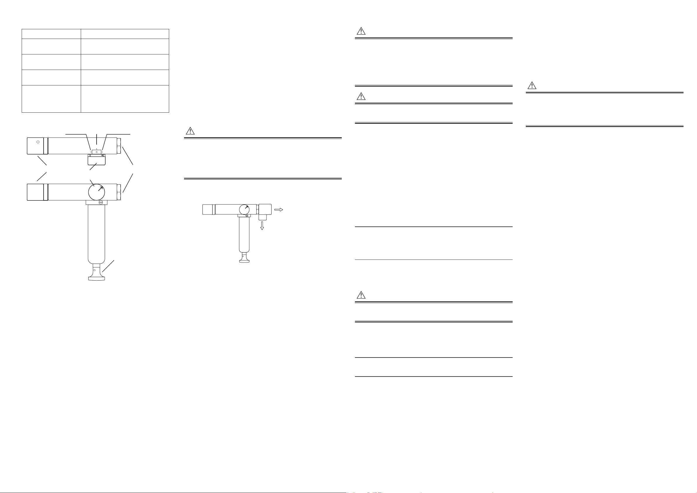
2. Components
Vent
3. Vernier adjustment
4. Pressure output
CAUTION
Standard pressure
Connector
<Connection example>
WARNING
CAUTION
WARNING
CAUTION
Name Description
1. Pressure/Vacuum
knob
2. Handle Operate (push) the handle to generate
3. Vernier adjustment Used to “fine tune” the pressure to the
4. Pressure output port
1/8" NPT
Turn the knob to switch between
Pressure, Vacuum, and Vent open.
pressure.
target value.
Port for outputting pressure.
Connect a standard pressure meter,
calibration target (connector),
and so on to this port.
(vent open)
1. Pressure/Vacuum
knob
PressureVacuum
VENT
PRESSUERVACUUM
port
2. Handle
3. Operating Instructions
3.1 Handling Precautions
Be sure to check the operating environment (safety).
Before use, be sure to check that connectors are secure,
that there are no intrusion of foreign substances,
and that there are no damages.
In addition, use the same thread specications for all connectors.
Perform preliminary pressure tests on tubing and other parts of
the system.
If you are applying pressure using a hand pump,
be sure to monitor the pressure with a standard pressure meter
(monitor).
3.2 Connecting Connectors
• Use connectors appropriate for the thread specications of
the device under test (DUT) and tubing.
Otherwise, leakage and damage to threads may result.
• Apply appropriate seal tape to the connecting surface of
the connector.
1/8” NPT
meter
The device under test
(DUT)
3.3 Generating Pressure
• Remove tubing and wiring from the the device under test (DUT)
before carrying out the procedure.
• Only connect to this pressure pump.
Do not connect to another high pressure source.
• Be sure to observe all safety precautions to avoid injury and
damage to the DUT.
Use connectors and hoses appropriate for the source pressure
value.
[ Procedure ]
(1) Connect the standard pressure meter and the DUT.
(2) Use the Pressure/Vacuum knob to select pressure or
vacuum.
(3) Push the handle to apply pressure near the target pressure
(operate the handle while checking the standard pressure
meter).
(5) Turn the vernier adjustment to “ne tune” the pressure to
the target value.
Increase: Turn clockwise
Decrease: Turn counterclockwise
Note
The vernier adjustment can be turned about 20 times
counterclockwise (decreasing pressure) from the maximum
position. If the adjuster feels heavy to turn, stop turning it.
Turning it by force can cause damage.
4. Troubleshooting
If you cannot increase the pressure with the hand pump
(if the pressure decreases), check the following.
• Check the pressure/vacuum knob position.
• Check the thread specications of the connection port.
Check that the connection is secure (use seal tape or
other measures).
If you cannot determine the cause, continuing with the procedure
is dangerous. Stop immediately.
If the product does not work properly, contact your nearest
YOKOGAWA dealer.
■UsingTwoWrenches
To prevent leakage, you must tighten the connector or
quick adapter rmly.
Using a wrench only on the connector side may break
the pressure pump.
Use two wrenches to prevent force from being applied to
the pressure pump.
(The same applies when you connect a connector to
the standard pressure meter.)
3.4 Releasing Pressure
To prevent accidents, safely return the pressure to zero
(release the pressure) before removing the connector and hose.
After generating pressure, carefully turn the pressure/vacuum
knob to the vent (vent open) position to release the pressure.
Note
After use, store the pressure pump in the hand pump case or
in a safe place.
IM 91051-01EN (P2)
 Loading...