

Page 1
The Clanp-on Probe (751552) is a product of Yokogawa Test & Measurement Corporation.
WARNING
CAUTION
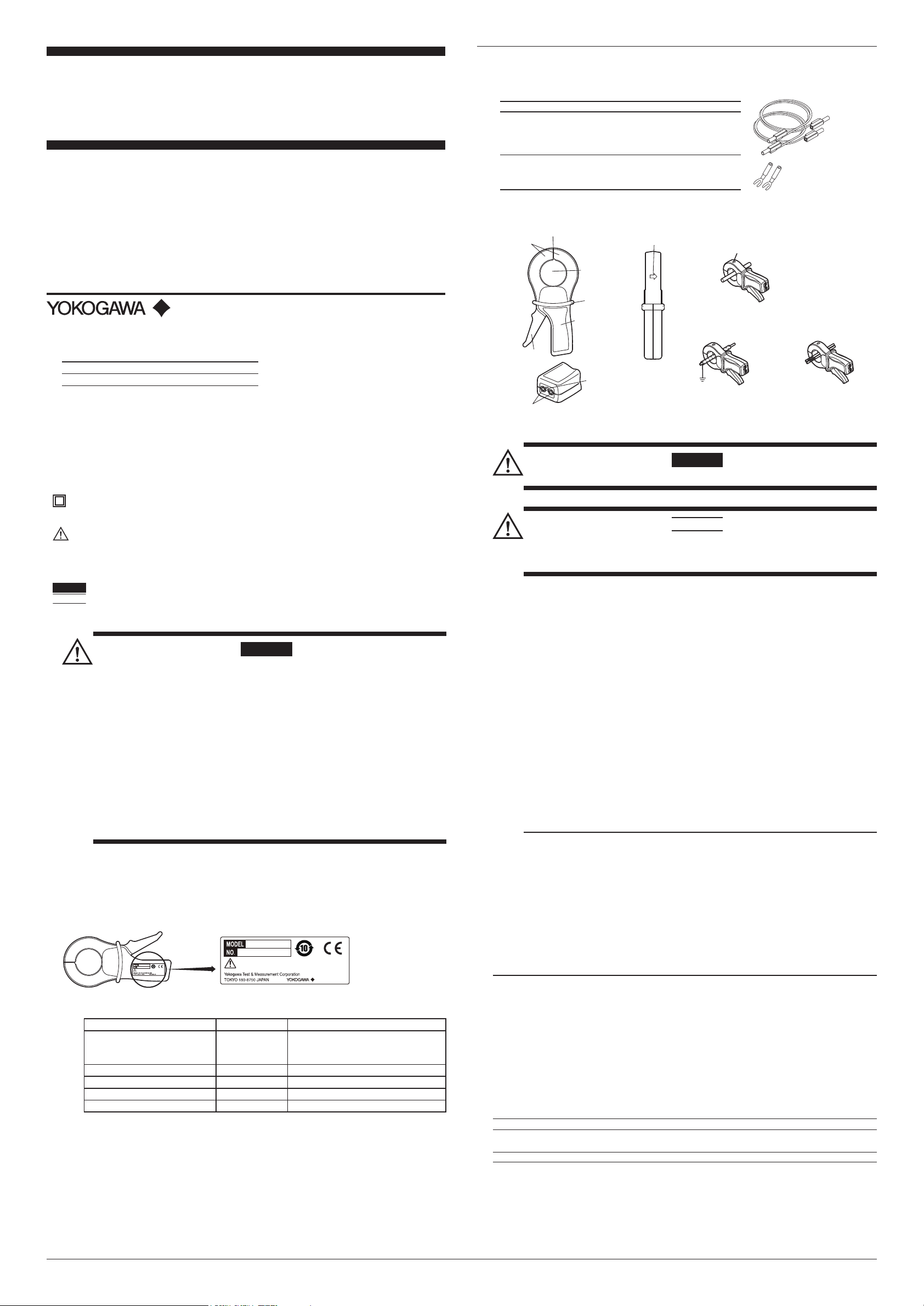
Name plate
(Opens and closes)
Jaws
Feed-through
hole
(for conductor)
Clamp lever
Direction of current
flowing through conductor
The direction of current flow
from the output terminal
Output terminals: Φ4 mm socket
Correct Use of Clamp
Incorrect Use of Clamp
Direction of current flow
Conductor
Using an Earth-Shielded
Conductor
Using Two Parallel
Conductors
Barrier
User's
Manual
751552
CLAMP-ON PROBE
IM 751552-01E
7th Edition
Thank you for purchasing the CLAMP-ON PROBE (Model 751552). In order to take advantage of all the
functions of the probe and to ensure proper use, please read this user's manual thoroughly before
beginning operation. Please familiarize yourself with the functions and characteristics of the probe prior
to operation. After reading this manual, keep it in a safe place.
7th Edition : March 2017(YMI)
All Rights Reserved, Copyright © 2002, Yokogawa Electric Corporation
All Rights Reserved, Copyright © 2014, Yokogawa Test & Measurement Corporation
Printed in Japan
Contact information of Yokogawa oces worldwide is provided on the following sheet.
Document No. Description
PIM 113-01Z2 List of worldwide contacts
Accessories (Sold Separately)
The optional accessories below are available for purchase separately. Use the accessories
specied in this manual. Moreover, use the accessories of this product only with Yokogawa
products that specify them as accessories.
758917
758921
Name
Measuring
Lead
Fork
Terminal
Adapter
Set
Model
Lot Qty.1Notes
758917
758921 1 2 pcs. per unit
2 pcs. per unit
Used in conjunction with the
adapter, model 758921, sold
separately
Length: 0.75 m, Rated Current: 32 A
For measuring leads, model
758917, sold separately
Rated Current: 25 A
3. Names of Parts
Safety Precautions
This product is designed to be used by a person with specialized knowledge.
Make sure to observe the following safety precautions when handling the probe. YOKOGAWA
assumes no liability for the customer’s failure to comply with these safety precautions. Before you
use the probe, read the measuring instrument’s manual to thoroughly familiarize yourself with the
specications and operations of the measuring instrument.
This manual is an essential part of the product; keep it in a safe place for future reference.
The following safety markings are used in this manual.
This instrument is protected by double-layer insulation or reinforced insulation that has the same level
Note Provides important information for the proper operation of the instrument.
of protection as double-layer insulation. It is not necessary to connect the instrument to protective
ground for safe use.
Improper handling or use can lead to injury to the user or damage to the instrument. This
symbol appears on the instrument to indicate that the user must refer to the user’s manual for
special instructions. The same symbol appears in the corresponding place in the user’s manual
to identify those instructions. In the manual, the symbol is used in conjunction with the word
“WARNING” or “CAUTION.”
Describes precautions that should be observed to prevent serious injury or death to the user.
Describes precautions that should be observed to prevent minor or moderate injury, or damage
to the instrument.
WARNING
• Do not exceed the maximum current. Doing so can result in erroneous measurement
or damage to the instrument.
• Beware of electric shock.
• Do not exceed 600 V, and do not use with a non-isolated conductor with a surge
exceeding measurement category III. Be sure to check the electric potential and
voltage surge before measurement.
• Do not perform measurement if the instrument is damaged.
• Always use the instrument indoors. Do not use the instrument in a rainy or humid
environment, or if water droplets form on its surface. Also, do not operate with wet
hands. Condensation may appear if sudden changes in temperature occur. If this
happens, let the device acclimatize to the new temperatures for at least one hour, then
refrain from using the device until conrming that there is no condensation.
• Always operate the instrument in the environmental conditions described in this manual.
• Always keep the clamp lever clean.
• Do not disassemble the device
The device should be disassembled by qualied personnel only.
1. Description
This device is a current output type clamp-on probe with a 1000:1 current transformation ratio that
performs transformation on the primary current.
2. Contents of the Package
Check that the model name given on the name plate on the grip match those on your order.
751552
751552
Read IM 751552-01
DATE OF
MANUFACTURE
XXXX.XX
Made in France
Read IM 751552-01
DATE OF
MANUFACTURE
XXXX.XX
Made in France
4. Performing Measurement
WARNING
Keep your ngers and hands behind the barrier.
CAUTION
Ensure that the current owing through the conductor being measured is within the
current r an ge. If the cur re nt range is exceeded, the device may overheat and become
damaged.
Operating Procedure
1. Enter the appropriate settings on the measuring instrument being used to accommodate the
output from the probe.
2. Connect measuring leads (758917, sold separately) to the probe's output terminals and the
measuring instrument. The connection method diers depending on the measuring instrument
being used. See your instrument's user's manual for the procedure. If the connector on the
measuring leads cannot be connected to the input terminals on the measuring instrument, use
a fork terminal (758921: sold separately) or other adapter.
Example • For a digital power meter, connect a lead from the red output terminal (+) to
the current input I terminal, and from the black output terminal (-) to the current
± terminal.
• For a digital multimeter, connect a lead from the red output terminal (+) to the
A terminal, and from the black output terminal (-) to the Lo terminal.
3. Squeeze the jaws to open the clamps, then position the conductor inside the feed-through
hole. Hold the probe so that the conductor is as closely in the center of the feed through hole
as possible.
4. Release the clamp lever to close the clamps. Steps 3 and 4 is called clamping.
5. Read the measured values on the measuring instrument. Calculate the current owing
through the conductor using an input/output ratio of 1000:1.
Example: Given that 150.0 mA is owing from the probe's output terminal,
current = 150.0 mA × 1000 = 150.0 A.
Note
• Close the clamp completely before taking measurements. Errors can occur If any foreign
objects or particles become trapped between the jaws.
• Only perform measurements on conductors in which the current is flowing in only one
direction. The device cannot correctly measure earth-shielded conductors or parallel
conductors with current owing in both directions.
• To reduce errors, use a measuring instrument with an internal impedance less than or equal to 1Ω.
• If DC current is superimposed on an AC current being measured, the output signal from the
clamp will become distorted and measurements will be inaccurate.
• When measuring phase dierence in voltage and current using an instrument such as a digital
power meter, make sure that the current ows in the same direction as the arrows on the probe.
The phase dierence can be correctly measured by positioning the clamp so that current ows
from the front side (name plate) to the reverse side (in the direction shown by the arrows on the jaws).
• Avoid locations with extremely strong external magnetic fields (other than the conductor
under test) as they may cause measurement errors.
Standard Accessories
Manuals
Manual Title Manual No. Description
751552 CLAMP-ON PROBE
User’s Manual
IM 751552-01E
This manual. This manual explains the
handling precautions, basic
usage, and specifications of the probe.
751552
751552 CLAMP-ON PROBE IM 751552-92 Document for China
751552 CLAMP-ON PROBE IM 751552-93Z2 Document for Republic of Korea
クランプオンプローブ
IM 751552-01
The Japanese version of the above manual
Inquiries PIM 113-01Z2 List of worldwide contacts
The “E” in the manual number is the language code.
5. Specications
Safety Standards Complying starndard: EN61010-1 & EN61010-2-032
Instrument with double insulation or reinforced insulation between primary, secondary
Operating voltage: 600 V Measur ement cat egory III
Operating voltage: 300 V Measur ement cat egory IV
Electromagnetic compatibility Complying standard: EN61326-1
Environmental standard
Current Range AC 0.001 to 1200 Arms. However, for 1000 to 1200 Arms, refer to the Maximum Current
Current Transformation Ratio 1000:1
Output Signal AC 1 mA/A (or 1 A/1000 A)
Accuracy and Phase shift (at Reference Conditions
PrimaryCurrentI 1≤I<100mA 0.1≤I<1A 1≤I<10A 10≤I<100A 100≤I≤1200A
%accuracyof ≤3%ofrdg+5µA ≤2%ofrdg+3µA ≤1%ofrdg ≤0.5%ofrdg ≤0.3%ofrdg
output signal (rdg: reading of output signal)
Phase shift Notspecied Notspecied ≤2deg ≤1deg ≤0.7 deg
Bandwidt h 30 Hz to 5 kHz (error in frequency inuence is added to Accuracy at Refer ence Con ditions).
Crest Factor 6 or less for a 2000 A peak (333 Arms) current or less
Maximum Current For a continuous frequency f of 1 kHz or less, I ≤ 1000 A
For frequencies exceeding 1 kHz, the current that can be allowed to ow continuously
For an input signal of 1000 A < I ≤ 1200 A at 1 kHz, the probe can be used continuously
and outer case parts.
Complying
industrial use
(Ipermanent) is calculated as follows:
for a maximum of 40 minutes. Do not perform measurements 20 minutes thereafter
standard: EN50581 Monitoring and control instruments including those for
‡
)
permanent
I
= 1000A/f(kHz)
*
, Pollution degree 2†.
*
, Pollution degree 2†.
IM 751552-01E 1/2
Page 2
Load Impedance 1 Ω or less
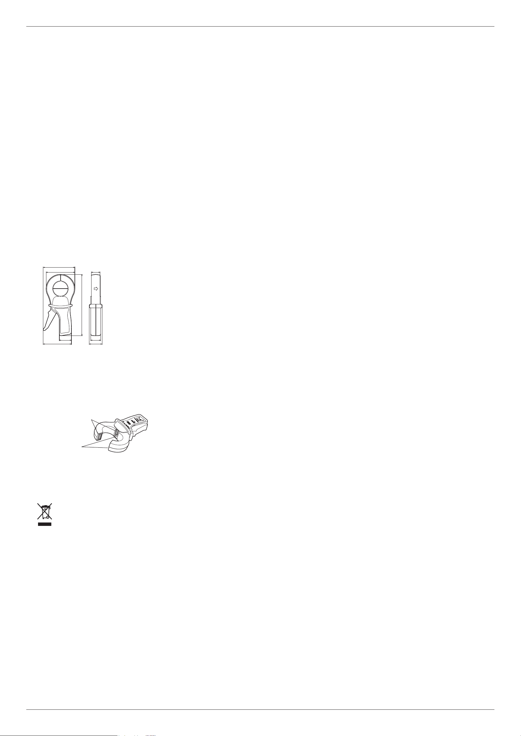
Four metal surfaces are
exposed with the clamp
is opened.
Metal surfaces
Max. Output Voltage 30 V peak or less (restricted by the output protection circuit).
Working Voltage Max. 600 Vrms
Inuence of Adjacent Conductor When the frequency of the current in an adjacent conductor is 50 Hz, the
Inuence of Conductor Position in the Jaws 0.1% or less in the output signal for a frequency of 400 Hz or less.
Inuence of Load Impedance r When 1 Ω < r ≤ 5 Ω, under 0.1% of output signal, and phase shift under 0.2 degrees
Inuence of Frequency f
65 Hz < f ≤ 1 kHz: under 1% of output signal
1 kHz < f ≤ 5 kHz: under 2% of output signal
Inuence of Crest Factor Under 1% of output signal, given a crest factor of 6 or less for a 2000 A peak
(333 Arms) current or less
Inuence of DC Current Superimposed on Nominal Current
Under 1% of the output signal, assuming a current of DC 15 A or less.
Operating Temperature –10°C to +50°C
Storage Temperature –40°C to +70°C
Temperature Inuence 0.02%/°C or less of the output signal
Operating Humidity 0 to 90% RH (no condensation) However, if 35°C is exceeded, humidity will impair the
Inuence of Humidity Under 0.1% of the output signal given 10% RH ≤ Humidity < 20% RH or
75% RH < Humidity ≤ 90% RH
Operating Altitude 2000 m or less above sea level
Max. Jaws Openin g 53 mm (open jaws height: 139 mm (W))
External Dimensions Approx. 111(W) x 216(H) x 45(D) mm
Weight Approx. 620g.
Output Safety jacks (Φ4 mm)
* Measurement category describes a number which denes a transient overvoltage condition. It implies the
regulation for impulse withstand voltage.
Measurement category III applies to measurement of the distribution level, that is , building wiring, xed
installations. Measurement category IV applies to measurement of the primary supply level, that is,
overhead lines, cable systems, and so on.
† Pollution degree describes the degree to which a solid, liquid, or gas which deteriorates dielectric strength
or surface resistivity is adhering.
Pollution Degree 2 applies to the normal indoor atmosphere. Normally, only non-conductive pollution
occures. Occasionally, however, temporary conductivity caused by condensation must be expected.
‡ Reference Conditions
Temperature: 23 °C±3°C Humidity: 20 to 75% RH External magnetic eld < 40 A/m
No AC magnetic eld Conductor centered in jaws Load impedance ≤ 1 Ω (≤ 1 VA)
No inuence of current owing in adjacent conductors
When the primary current is sinusoidal, the sinusoidal conditions are: frequency; 48 to 65 Hz, distortion
factor < 1%, no DC component
§ There is no frequency inuence in the range 48 Hz ≤ f ≤ 65 Hz.
inuence on the primary current is 0.5 mA/A or less.
§
30 Hz ≤ f < 48 Hz: under 0.5% of output signal
primary functionality (by a factor of 0.5% RH/°C)
External Dimensions (Units: mm)
111
101
52
31
216
43.5
99
35
45
6. Maintenance
• Note the following when cleaning the probe.
• Do not clean the probe while clamped to a conductor. Likewise, do not clean while
• Do not allow water to contact the jaws.
connected to a measuring instrument.
• When opening the jaws, keep the exposed metal areas clean. If dust accumulates, wipe with a
clean dry cloth. To prevent rust, wipe metal surfaces with oil from time to time. Avoid getting oil on
non-metallic surfaces. Use only high quality, low-viscosity machine oil such as sewing machine oil.
• This product undergoes a 100% inspection at the time of shipment. If any layers of the core
come apart slightly during shipment, this will not aect the functioning of the product.
7. Servicing
If you encounter any problems during use, or if the device does not appear to be operating normal-
ly, contact your dealer or nearest YOKOGAWA representative.
8. Appendix
Waste Electrical and Electronic Equipment
Waste Electrical and Electronic Equipment (WEEE), Directive
(This directive is valid only in the EU.)
This product complies with the WEEE directive marking requirement. This marking
indicates that you must not discard this electrical/electronic product in domestic
household waste.
Product Category
With reference to the equipment types in the WEEE directive, this product is classied
as a “Monitoring and control instruments” product.
When disposing products in the EU, contact your local Yokogawa Europe B.V. oce.
Do not dispose in domestic household waste.
Authorized Representative in the EEA
Yokogawa Europe B. V. is Authorized Representative of Yokogawa Test & Measurement Corporation
in the EEA for this Product. To contact Yokogawa Europe B. V., see the separate list of worldwide
contacts, PIM 113-01Z2.
IM 751552-01E 2/2
 Loading...