


v


Table of Contents
1
Table of Contents
Table of Contents ........................................................................... 1
Introduction.................................................................................... 3
Key Tasks for Deployment .................................................................................................................................... 3
DECT Transmission Technology .................................................... 4
DECT Transmission Glossary ................................................................................................................................ 4
Synchronization Technology ............................................................................................................................... 4
Cluster ...................................................................................................................................................................... 4
Sync Level ............................................................................................................................................................... 5
Signal Transmission................................................................................................................................................. 7
DECT IP Multi-Cell Deployment ToolKit ...................................... 8
Using the ToolKit ...................................................................................................................................................... 8
Display in Metering Mode .................................................................................................................................... 9
Deployment Guidance ................................................................. 10
Data References ..................................................................................................................................................... 10
Number of Simultaneous Calls .................................................................................................................... 10
System Capacity ................................................................................................................................................ 10
Limit Values ......................................................................................................................................................... 12
Installation Height of the Base .................................................................................................................... 13
Estimating the Number of the Base Stations ............................................................................................. 13
Estimation Based on the Total Coverage Area ...................................................................................... 13
Estimation Based on the Total Number of Handsets ......................................................................... 15
Placement Strategies of Base Stations ..................................................................................................... 15
Preliminary Determination of the Positions of the Base Stations ...................................................... 16
Creating a Planning Drawing ....................................................................................................................... 16
Positioning the Base Stations in the Planning Drawing .................................................................... 17
Taking Measurements ................................................................. 19
Recommendations for Measurement Sequence ...................................................................................... 19
Measuring the Voice Quality at the Measuring Points .......................................................................... 19
Measuring the Signal Strength between two Base Stations ................................................................ 22

Yealink W80 DECT IP Multi-Cell System Deployment Guide
2
Deployment in a Multi-Storey Building ..................................... 24
Installing the W80DM/W80B ...................................................... 25

Introduction
3
Introduction
This guide explains the necessary preparations for the installation of a DECT IP multi-cell system and how
to take measurements for the optimum positions of the base stations. It also provides some technical and
practical background information.
Key Tasks for Deployment
Deploy the Multi-Cell System
Install the base stations based on the measurement results.
Take Measurements
Take measurements, and record the results.
Estimate the Base’s Position
1. Create a planning drawing.
2. Position the base stations in the planning drawing.
Analyze Requirements
1. Confirm the requirements.
2. Collect environmental information.

DECT Transmission Technology
4
DECT Transmission Technology
DECT Transmission Glossary
LA (List Access)
All menus access by the handset that needs to interact with the base station.
WB (Wide Band)
One base station supports a maximum of four active handsets.
NB (Narrow Band)
One base station supports a maximum of eight active handsets.
Synchronization Technology
The base stations in a multi-cell DECT network must synchronize with each other. The synchronization
can ensure a seamless handover and roaming for the LA and calls in the multi-cell system.
Cluster
A cluster comprises a number of base stations in the DECT IP multi-cell system that synchronize with each
other to enable handover, roaming and load balancing.
Handover: The DECT connection of a handset is passed to another base station during a call.
Roaming: A handset in the idle status is connected to the multi-cell system via a new base station.
Load Balancing: Because the current base station is overloaded with active DECT or media connections,
the DECT connection is set up with a neighboring base station having free resources for a call.
Handover and load balancing take effects only when the base stations are synchronized with each other.

Yealink W80 DECT IP Multi-Cell System Deployment Guide
5
Single Cluster Only
All base stations in the multi-cell system belong to a cluster, where they can synchronize with each other.
Multiple Clusters
Base stations that are far apart in the multi-cell system can be grouped into different clusters, where the
synchronization is not required. So there is no handover between two clusters.
Sync Level
Each base station is assigned to a corresponding sync level.
Sync Level 1
Highest Level
Appears only once
in each cluster
A base station always synchronizes itself with a base station that has a higher sync level. If it detects
several base stations with a higher sync level, it synchronizes itself with the base station that has the

DECT Transmission Technology
6
strongest signal. If it does not detect any base station with a higher sync level, it cannot synchronize.
Detect the base station
with a hi gher sync level?
Base station X
Cannot synchronize.
Synchronize itself with
the base station that has
the strongest signal.
Y N
More than one
base station with a higher
sync level?
Synchronize directly.
Y N
The more synchronization levels, the greater the possibility of synchronization loss. So select the base
station that is in the center of your DECT network as the base station with sync level 1.
Your synchronization hierarchy could also look like as the following:

Yealink W80 DECT IP Multi-Cell System Deployment Guide
7
Signal Transmission
The ideal signal transmission of a base station is omni-directional. All registered handsets can be the
same distance away from the base station in all directions without the wireless signal being interrupted.
But the range is usually influenced by a variety of environmental conditions. You have to investigate the
actual conditions by measuring the signal transmission of the base stations at the appropriate positions.
The following table gives some general guidelines on the degree to which certain materials will reduce
signal strength:
Materials
Degree of Attenuation
Examples
Air
None
Open space
Wood
Low
Door, floor, partition
Plastic
Low
Partition
Glass
Low
Un-tinted glass, partition
Tinted glass
Medium
Tinted glass, partition
Living creatures
Medium
Crowds, plants
Bricks
Medium
Walls
Plaster
Medium
Partitions
Ceramic
High
Tiles
Concrete
High
Load-bearing walls, floors, pillars
Metal
Very High
Reinforced concrete, metal cabinet
DECT IP Multi-Cell Deployment ToolKit
8
DECT IP Multi-Cell Deployment ToolKit
Yealink offers the DECT IP Multi-Cell Deployment ToolKit to help you plan and install your DECT IP
multi-cell system.
You can use the measuring devices in the kit to determine the radio coverage at your position, establish
all base stations required for a given installation and their optimal positions, and find sources of
interferences in the DECT wireless network.
For more information on the kit, refer to
Yealink DECT IP Multi-Cell Deployment ToolKit Quick Start
Guide
.
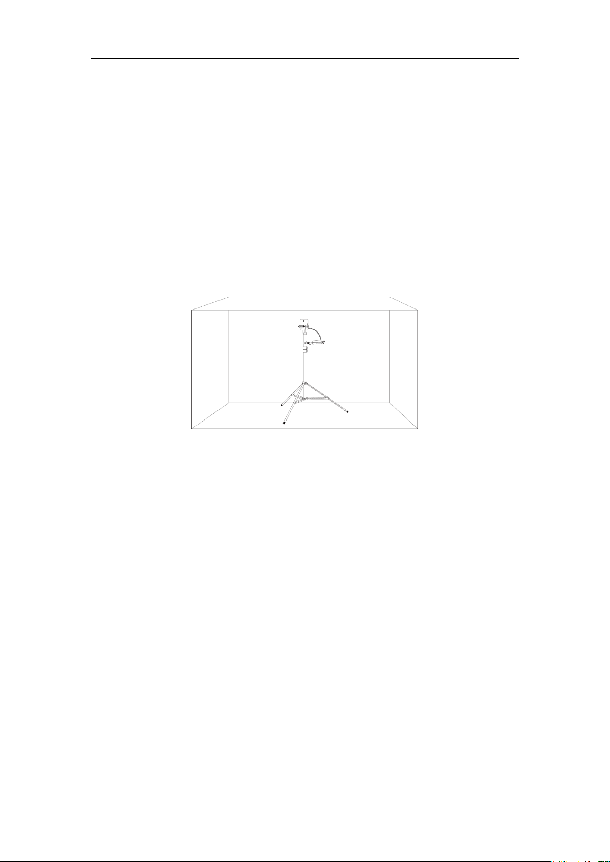
Using the ToolKit
1. Select the first measuring point, mount the base station to a proper position on the stand, and
charge it using the mobile power.
Note: The stand height can be adjusted from 3.28 feet (1.00 meter) to 9.19 feet (2.80 meters).
2. Enter the code *1234203# in the handset’s idle screen to activate the metering mode.
3. Set up communications between two handsets in the metering mode, and measure the radio
coverage.
You can connect headsets to the measuring handsets so that you can assess the quality of the sound
transmitted from the measuring base station. It also means that your hands are free to enter the
positions determined in the plan and you can read the LCD screen during the measurement.
4. Check the current status values of the connection to determine the second position of the base
station.
The recommended RSSI value is between -27 dBm and -85 dBm (subject to actual call), and the
Frame quality is 100%.
5. Move the base station to the second position, and adjust it to a proper position of the stand.
6. Repeat the above steps to determine more positions of the base station.

Yealink W80 DECT IP Multi-Cell System Deployment Guide
9
Display in Metering Mode
RSSI: Received Signal Strength Indication. Base station signal reception strength with the best reception
in dBm.
Recommended value: -27 to -85 dBm. (subject to actual call)
Note: The RSSI value is displayed in dBm as standard, you can change it into a percentage value.
Fr. quality: Frame quality. Percentage rate of the packages received without error in the last measuring
interval.
Recommended value: 100%.
Base Station: RPN (Radio Fixed Part Number) of the base station. Identifier for the base station to which
the handset is connected.
Frequency: Carrier frequency of the signal received.
Value range: 0-30.
Slot pair: Time slot for the reception channel on which the measurement was performed.
Duplex Slot pair used (0-11).

Deployment Guidance
10
Deployment Guidance
Data References
Number of Simultaneous Calls
The following table shows the maximum number of simultaneous calls in relation to the number of W80B:
Number of
W80B
Maximum Number of Simultaneous Call
Maximum Number of Active Handset
Wide Band
Narrow Band
Wide Band
Narrow Band
1 8 8 4 8 2 16
16 8 16
3
24
24
12
24 4 32
32
16
32 5 40
40
20
40 6 48
48
24
48
7
50
50
28
50 8 50
50
32
50
9
50
50
36
50
10
50
50
40
50
11
88
88
44
88
12
96
96
48
96
13
100
100
52
100
…30
100
100
100
100
System Capacity
The capacity of the DECT multi-cell system must be high enough to guarantee that subscribers can be
reached in high-density traffic. Both the capacity of the entire DECT system and the capacity of the
individual wireless cells must be taken into account.
The capacity of the DECT multi-cell system is determined by the following factors:
Number of connection channels available
The number of connection channels available defines how many connections can be managed

Yealink W80 DECT IP Multi-Cell System Deployment Guide
11
simultaneously.
Note: A connection channel is not only needed for phone calls. All LA actions occupy a connection
channel, such as the access to the history or remote phone book.
Grade of service (GoS)
The GoS determines the number of connections that may not be achieved due to the system being
at full capacity.
Loss of Range
The wireless range of a base station for handsets is (guideline values):
In the building: radius < 50m
In the open air: radius < 300m
These two values do not apply to the maximum possible distance between two base stations. To ensure a
seamless handover from the wireless cell of one base station to the one of another, the overlap zone is
necessary. Fewer obstacles between two base stations increase the possible distance between them.
Different building materials (common building) for the signal attenuation can refer to the following table:
Insertion
ae (dB)
Range Loss (%)
Brick wall, 10 to 12 cm
2.5
~ 43.5
Brick wall, 24 cm, small windows
4
~ 60
Brick wall, 63 to 70 cm
4.0 to 4.5
~ 60 to 64
Drywall
1.3 to 2.3
~ 26.5 to 41
Gaseous-concrete wall
6.6
~ 78
Glass wall 2 ~ 37
Wire-reinforced glass wall
8
~ 84
Reinforced concrete ceiling (residence)
6 to 9
~ 75 to 87
Two reinforced concrete ceilings
26
~ 99.5
Three reinforced concrete ceilings
46
100
The capacity must always be adjusted to the highest possible traffic volume if capacity bottlenecks
are to be excluded.
Traffic Volume
The traffic volume is expressed in “erlangs (E)”. One erlang corresponds to the continuous full capacity
utilization of a connection channel in one hour. It can be used to calculate the number of base stations.
For example, 300 calls (of 5 minutes each) would be necessary in one hour
Calculation: 300 x 5min/60min = 25 E
So for the volume of traffic accepted, at least 25 connection channels would be necessary. So at least 4
(3.13) base stations are needed when choosing to use the narrow band.
With a grade of service of 5%, it is permissible for 5% of 300 calls (15 connections) not to be established.

Deployment Guidance
12
This means that only 285 connections have to be achieved.
Note: Grade of Service (GoS) determines the number of connections that may not be achieved due to the
system being at full capacity. For example, the line is engaged. A grade of service of 5% means that out of
100 calls, 5 cannot be connected for capacity reasons.
Calculation: 300 x (1-5%) x 5min/60min = 23.75 E
So for the volume of traffic accepted, at least 24 connection channels would be necessary. So at least 3
base stations are needed when choosing to use the narrow band.
Since the traffic volume is not normally evenly distributed over the site to be covered, the traffic volume
must be calculated for each area (for example, offices, hotspots, stairwell) in order to determine the
relevant number of base stations that need to be installed.
Limit Values
During the measurement, the measuring handsets receive wireless signals from the measuring base
station and display various characteristics for the reception quality. The following are relevant for the
reception quality.
Reception power
Connection quality
Limit values for normal, interference-free conditions are:
1. Limit value for guaranteed call quality: -80 dBm
This is the value at which a handset needs to receive the base station signal so that a subscriber is
able to make good-quality calls. For an interference-free handover, the handset must receive both
base stations at this level of quality.
2. Limit value for synchronization: –85 dBm
This is the value at which a base station must receive another base station signal to ensure
synchronization.
Note: The recommended value is only a theoretical value, which can be adjusted according to
different deployment environments. If it is a relatively empty environment, you can try to move to a
farther location. If it is a building with more blocks, it is recommended to keep it at -85 dBm. The
final position can be based on the actual call, which can ensure the stability of the system and
improve the coverage of the base station. If you do not use a professional deployment tool, you
need to take the actual synchronization effect as the standard.
In principle, the measurement of the field strength should always be supplemented by checking the
connection quality (frame quality). Interference, for example, through reflection or external systems that
influence the voice quality, can occur with good reception power as well.

Yealink W80 DECT IP Multi-Cell System Deployment Guide
13
The Frame quality indicates the percentage of packages received without errors in a measurement
interval.
Reception Power
RSSI
Frame Quality
Quality Evaluation
-48 dBm < x < -28 dBm
0xA8 < x < 0xD8
100%
Good
-58 dBm < x < -48 dBm
0x90 < x < 0xA8
100%
Satisfactory
-66 dBm < x < -58 dBm
0x78 < x < 0x90
100%
Adequate
-80 dBm < x < -66 dBm
0x50 < x < 0x78
100%
Weak
-95 dBm < x < -80 dBm
0x30 < x < 0x50
100%
Poor
-xx dBm < x < -95 dBm
0x00 < x < 0x30
100%
Disconnected
Installation Height of the Base
The recommended installation height for a base station is between 1.80 meters and 3 meters depending
on the room height. There should be a minimum clearance of 0.5 meters to the ceiling.
Estimating the Number of the Base Stations
The following requirements must be considered when estimating how many base stations are required
and deciding where they should be placed:
Sufficient DECT radio coverage of the entire site so that each subscriber can be reached.
Sufficient wireless channels (DECT bandwidth), particularly in “hotspots”, to avoid capacity
bottlenecks.
Sufficient overlap of wireless cells to enable synchronization between base stations and to
guarantee the free movement for subscribers when making calls.
Estimation Based on the Total Coverage Area
Estimate the approximate number of base stations according to the total area of expected radio
coverage.

Deployment Guidance
14
Request the building plan and confirm the following:
The calculation can be the following:
Number of the base stations = [the size of the coverage area (in square meters)] / 800
The suggested distance between two base stations depends on the physical path between the base
stations.
The following table lists the recommended distance between two base stations:
Area
Distance between two base stations
Office areas
Up to 40 meters
Office areas with obstacles like elevator shafts,
stairwells or metal walls
Up to 10 meters
Shop floors
Up to 60 meters
Exhibition halls or production areas without
obstacles
Up to 100 meters
Underground garages
Up to 20 meters
As the base stations can interfere with each other, you should maintain sufficient distance between two
base stations. The minimum distance depends on the circumstance. If there are no obstacles between
them, the required distance can be 5 to 10 meters. If there is an absorbent wall or absorbent furniture
between them, 1 to 2 meters may be sufficient.
Environment
Conditions
Building
materials
Position and
dimension of
the room
Total area of
the required
radio
coverage
Number of
floors
Construction
changes in
the future

Yealink W80 DECT IP Multi-Cell System Deployment Guide
15
Estimation Based on the Total Number of Handsets
Confirm the following:
1. How many employees need to make phone calls and how many subscribers may make
simultaneous calls?
2. How many calls will be made?
How long is the average call?
Where are the hotspots, that is, where do a lot of subscribers gather simultaneously (office
area/meeting room/canteen)?
Where are telephone conferences held? And how many telephone conferences are held?
Placement Strategies of Base Stations
The following tips you need to know when selecting a position for the base station:
Considering the coverage of wireless signals in the building, it is better to install the base stations at
the corridor intersection.
Subscribers’
Requirements
Call volume
Average call
duration
Location of
the
conference
call
Hotspots

Deployment Guidance
16
In a multi-storey building, we recommend that you install additional base stations in the stairwells.
Multi-storey
building
Install additional base
stations in the stairwells.
Do not install the base stations in suspended ceilings, cupboards or other closed furniture. The radio
coverage will be significantly reduced, depending on the materials used.
Avoid installing the base stations in the direct vicinity of cable channels, metal cupboards or other
larger metal devices. They can reduce the radiation and couple into interfering signals.
Preliminary Determination of the Positions of the Base
Stations
After estimating the number of the base stations, you can create a planning drawing and position the
base stations in the planning drawing now.
Creating a Planning Drawing
Create a planning drawing from the information you have collected in the preliminary examination of the
position. Enter building dimensions, hotspot areas and any sources of interference already identified.
Cupboards
Suspended
ceilings
Closed
Furniture

Yealink W80 DECT IP Multi-Cell System Deployment Guide
17
Example:
The different lines indicate different building materials.
Loss of radio coverage range of the base stations through building materials:
Building Materials
Degree of Attenuation
Metal
Very High
Brick walls
Medium
Glass
Low
Concrete walls
High
Note: There is no need to consider these exterior walls.
The numbers in the rooms reflect the traffic volume of the DECT phones.
Areas with high-density traffic are marked as hotspots (HS).
Positioning the Base Stations in the Planning Drawing
After creating a planning drawing, position the preliminary position in the planning drawing.

Deployment Guidance
18
Example:
The example shows six preliminary positions of base stations (A, B, C, D, E, and F).
You need to set a corresponding sync level for each base station according to the preliminary
positions. Generally, start with the base station for which a subsequent change would mean the
greatest effort. This is the base station with sync level 1. And then move outwards from sync level to
sync level.
Here, we set the following:
Sync Level 1: Base station A
Sync Level 2: Base station B, base station C, base station E
Sync Level 3: Base station D, base station F
The example shows nineteen measuring points (1 to 19).
These measuring points should be selected in the corner and where are not easily covered by the
signal theoretically.
For the hotspot in the office room, two additional base stations are planned in parallel.
You should also check whether the base stations planned are sufficient for the second hotspot
(after-sales department).
Check these preliminary estimations later by Taking Measurements.

Taking Measurements
19
Taking Measurements
For actual measurement, we need to make sure the following three aspects meet the deployment
requirements.
Are sufficient radio coverage and a good voice quality guaranteed everywhere in the planned
network?
Is synchronization of the base stations ensured in the planned positions?
Is a roaming or a handover possible in the multi-cell system?
Recommendations for Measurement Sequence
You may need to fine-tune the position of the base station as there is some error between the estimation
and measurement.
In order to adjust as little as possible, you should follow the following measuring principles:
Measuring the Voice Quality at the Measuring Points
Measure the voice quality transmitted from the measuring base station in the wireless cell. It is used to
ensure that excellent voice quality is guaranteed at every position in the required coverage area. Taking
the same measurement for the neighboring base station that produces the overlap area required for a
handover.
Preferential
measurement
High-risk area
Highest sync
level
Hotspots
Position adjustment is relatively impossible.
For example, stairwells, entrance area, computer room.

Yealink W80 DECT IP Multi-Cell System Deployment Guide
20
Procedure
1. Temporarily fix the measuring base station in the planned position where it will be installed.
2. Establish a phone connection between the two measuring handsets, observing the display and the
signal in the headset, until the limit value of -80 dBm is displayed or a wireless transmission
boundary is reached. Transfer this point to your plan and record the value in the measurement log.
3. Check the voice quality in the limit areas using the connection to the second measuring handset.
4. Record the deviations in the reception signal measurement of the voice quality in the measurement
log.
Example of a measurement log for the cells of multiple base stations:
Measuring
Point
Base A
Base B
Base C
Base E
Base D
Base F
1
√ √ √
2
√ √ √ 3 √ √ √
4
√
√ 5 √ 6 √ 7 √
8
√
9
√
10
√

Taking Measurements
21
Measuring
Point
Base A
Base B
Base C
Base E
Base D
Base F
11
√
√
12
√
√
13 √ 14
√
15
√
√
16
√
√
17
√
√
18
√
19
√
The measuring results may look like this, for example:
Measuring Point
Base A
Base B
Base C
Base E
Base D
Base F
1
-55dBm/100%
-52dBm/100%
-49dBm/100%
2
-50dBm/100%
-54dBm/100%
-35dBm/100%
3
-47dBm/100%
-30dBm/100%
-50dBm/100%
4
-50dBm/100%
-50dBm/100%
5
-62dBm/100%
6
-61dBm/100%
7
-57dBm/100%
8
-64dBm/100%
9
-63dBm/100%
10
-52dBm/100%
11
-57dBm/100%
-59dBm/100%
-55dBm/100%
12
-60dBm/100%
-50dBm/100%
13
-53dBm/100%
14
-58dBm/100%
15
-52dBm/100%
-35dBm/100%
16
-50dBm/100%
-34dBm/100%
17
-53dBm/100%
-40dBm/100%

Yealink W80 DECT IP Multi-Cell System Deployment Guide
22
Measuring Point
Base A
Base B
Base C
Base E
Base D
Base F
18
-52dBm/100%
19
-40dBm/100%
Note: During the measurement, it is necessary to focus on the measuring point that only be covered by
one base station. For example, point 9, 10 and 19. Once the DECT signal fails to meet the requirements at
a certain test point, the position of the preset base should be adjusted in time.
Measuring the Signal Strength between two Base
Stations
Measure the signal strength transmitted from the measuring base station that you receive at the planned
position of the neighboring base station. It is used to ensure that sufficient synchronization overlap is
guaranteed.
For the base stations to be able to synchronize, we recommend that the signal value between two
neighboring base stations be kept above -85 dBm.
Procedure
1. Leave the first-level base station at the planned position and place the measuring handset to the
planned position of a second-level base station that is to synchronize with the first base station.
2. Check whether the signal is within the limit of -85 dBm at 100% frame quality.
3. Record the results in the measurement log.
4. Take this measurement for all planned positions.
Note: In order to keep measurement results correct, the measuring handset should be placed at the exact
position of the planned base station.

Taking Measurements
23
Example of a measurement log for the synchronization overlap of neighboring base stations:
Measuring
Point
Base A
Base B
Base C
Base E
Base D
Base F
A
√ √ √
B
√
√ C √
√
√
D
√ E √
√
√ √ √ F √
Measuring
Point
Base A
Base B
Base C
Base E
Base D
Base F
A
-37dBm/100%
-39dBm/100%
-61dBm/100%
B
-35dBm/100%
-47dBm/100%
C
-40dBm/100%
-45dBm/100%
-68dBm/100%
D
-53dBm/100%
E
-60dBm/100%
-70dBm/96%
-66dBm/100%
-50dBm/100%
-60dBm/100%
F
-60dBm/100%
The result of the measurement is that the signal strength is sufficient for synchronization everywhere.
Base station F and D can only receive base station E with sufficient quality, and base station B, C and E can
only receive base station A with sufficient quality.
Here, a sensible synchronization hierarchy would be:
Sync Level 1: Base station A
Sync Level 2: Base station B, base station C, base station E
Sync Level 3: Base station D, base station F

Yealink W80 DECT IP Multi-Cell System Deployment Guide
24
Deployment in a Multi-Storey Building
If a handover must be guaranteed among the floors in a building, you need to consider installing a
dedicated base station in the stairwells.
As is shown, the seventh base station (point M) should be added in the planning:
In this case, guarantee the synchronization among floors first, and then on the floor. So you need to
measure the radio coverage of the base stations in the stairwells.

Installing the Base Stations
25
Installing the W80DM/W80B
Once you complete the measurements, and the positions of the base stations have been determined, you
can install the W80B. Refer to the Quick Start Guide for more information about the installation.
The following points require additional attention:
1. After the installation, the multi-cell system will be synchronized soon. You should check the voice
quality, roaming, and handover again.
2. For each position please note down the MAC address of the device you are going to install.
The MAC address can be found on the rear of the device.
3. We recommend that you place W80DM in a protective position.
 Loading...