

Yaskawa Sigma-5 User Manual
AC Servo Drives
Σ-V Series
/DC Power Input
/
Σ-V Series for Large-Capacity Models
Σ-V Series
USER’S MANUAL
MECHATROLINK-II Commands
MANUAL NO. SIEP S800000 54G
MECHATROLINK-II Commands
Operation Sequence
Commands for Preparation Process
Motion Commands for Operation
Command Related Parameters
MECHATROLINK-II Subcommands
Data Field
Detecting Alarms/Warnings Related to
Communications or Commands
Appendix
1
2
3
4
5
6
7
8
App

Copyright © 2007 YASKAWA ELECTRIC CORPORATION
All rights reserved. No part of this publication may be reproduced, stored in a retrieval system,
or transmitted, in any form, or by any means, mechanical, electronic, photocopying, recording,
or otherwise, without the prior written permission of Yaskawa. No patent liability is assumed
with respect to the use of the information contained herein. Moreover, because Yaskawa is constantly striving to improve its high-quality products, the information contained in this manual is
subject to change without notice. Every precaution has been taken in the preparation of this
manual. Nevertheless, Yaskawa assumes no responsibility for errors or omissions. Neither is
any liability assumed for damages resulting from the use of the information contained in this
publication.

About this Manual
This manual describes the specifications of MECHATROLINK-II commands used for the following
MECHATROLINK-II communications reference input type SERVOPACKs, the basic operations using these
commands, and the parameters for these commands.
• Σ-V Series SERVOPACKs (Model: SGDV-11, and -15)
• DC Power Input Σ-V Series SERVOPACKs (Model: SGDV-E11)
• Large-Capacity Σ-V Series SERVOPACKs (Model: SGDV-11)
Targeted Readers
Users who incorporate MECHATROLINK-II commands in controllers
Users who design applications for host controllers that directly transmit MECHATROLINK-II commands
Related Documentation
Refer to the following manuals for information on Σ-V series SERVOPACKs, including hardware, adjustment
methods, and trial operation.
Σ-V Series Product Catalog KAEP S800000 42
Large-Capacity Σ-V Series Catalog KAEP S800000 86
Σ-V Series User’s Manual Setup Rotational Motor SIEP S800000 43
Σ-V Series User’s Manual Setup Linear Motor SIEP S800000 44
Σ-V Series User’s Manual Design and Maintenance
Rotational Motor/MECHATROLINK-II Communications Reference
Σ-V Series User’s Manual Design and Maintenance
Linear Motor/MECHATROLINK-II Communications Reference
DC Power Input Σ-V Series User’s Manual Setup Rotational Motor SIEP S800000 80
DC Power Input Σ-V Series User’s Manual Design and Maintenance
Rotational Motor/MECHATROLINK-II Communications Reference
Σ-V Series User’s Manual for Use with Large-Capacity Models Setup Rotational Motor SIEP S800000 89
Σ-V Series User’s Manual for Use with Large-Capacity Models Design and Maintenance
Rotational Motor/MECHATROLINK-II Communications Reference
Manual Name Manual Number
SIEP S800000 46
SIEP S800000 48
SIEP S800000 82
SIEP S800000 90
Be sure that you fully understand each command and use the commands in the order
appropriate for your application.
Incorrect usage of the commands can result not only unexpected motions, but in a serious accident.
Special care and verification must be taken for usage of the commands in order to avoid
accidents.
Be sure to also establish safety measures for the system.
General Precautions
Observe the following general precautions
• The products shown in illustrations in this manual are sometimes shown without covers or protective guards.
Always replace the cover or protective guard as specified first, and then operate the products in accordance with
the manual.
• The drawings presented in this manual are typical examples and may not match the product you received.
• If the manual must be ordered due to loss or damage, inform your nearest Yaskawa representative or one of the
offices listed on the back of this manual.
to ensure safe application.
iii

Warranty
(1) Details of Warranty
Warranty Period
Warranty Scope
The warranty period for a product that was purchased (hereinafter called “delivered product”) is one year from
the time of delivery to the location specified by the customer or 18 months from the time of shipment from the
Yaskawa factory, whichever is sooner.
Yaskawa shall replace or repair a defective product free of charge if a defect attributable to Yaskawa occurs
during the warranty period above. This warranty does not cover defects caused by the delivered product reaching the end of its service life and replacement of parts that require replacement or that have a limited service
life.
This warranty does not cover failures that result from any of the following causes.
1. Improper handling, abuse, or use in unsuitable conditi
logs or manuals, or in any separately agreed-upon specifications
2. Causes not attributable to the delivered product itself
3. Modifications or repairs not performed by Yaskawa
4. Abuse of the delivered product in a manner in which it was not originally intended
5. Causes that were not foreseeable with the
ment from Yaskawa
6. Events for which Yaskawa is not responsible, such as natural or human-made disasters
scientific a
ons or in
nd technological understanding at the time of ship-
environments not described in product cata-
(2) Limitations of Liability
1. Yaskawa shall in no event be responsible for any damage or loss of opportunity to the customer that arises
due to failure of the delivered product.
2. Yaskawa shall not be responsible for any programs (inclu
execution of the programs provided by the user or by a third party for use with programmable Yaskawa
products.
3. The information described in product catalogs or manuals
chasing the appropriate product for the intended application. The us
are no infringements of intellectual property rights or other proprietary rights of Yaskawa or third parties,
nor does it construe a license.
4. Yaskawa shall not be responsible for any damage arising
or other proprietary rights of third parties as a result of using the information described in catalogs or manuals.
g parameter settings) or the results of program
din
is p
rovided for the purpose of the customer pur-
e thereof does not guarantee that there
from
infringements of intellectual property rights
iv

(3) Suitability for Use
1. It is the customer’s responsibility to confirm conformity with any standards, codes, or regulations that
apply if the Yaskawa product is used in combination with any other products.
2. The customer must confirm that the Yaskawa product is suitable for the systems, machines, and equipment
used by the
3. Consult with Yaskawa to determine whether use in the
application is acceptable, use the product with extra allowance in ratings and specifications, and provide
safety measures to minimize hazards in the event of failure.
• Outdoor use, use involving potential chemical contamination
tions or environments not described in product catalogs or manuals
• Nuclear energy control systems, combustion systems,
tems, medical equipment, amusement machines, and installati
ernment regulations
• Systems, machines, and equipment
• Systems that require a high degree of reliability, such as systems th
systems that operate continuously 24 hours a day
• Other systems that require a simi
4. Never use the product for an application involving serious risk to life or property without first ensuring that
the system
Yaskawa product is properly rated and installed.
5. The circuit examples and other application examples described in product catalogs and manuals are for reference. Check the functionality and safety
product.
6. Read and understand all use prohibitions and
prevent accidental harm to third parties.
customer
is designed to secure the required level of safety with risk warnings and redundancy, and that the
.
applications is acceptable. If use in the
or electrical interference,
, aviation systems, vehicle sys-
ons subject to separate industry or gov-
at supply gas, water, or electricity, or
Yaskawa product correctly to
or use in condi-
that may
high degree of safety
lar
present a risk to life or property
he actual devices and equipment to be used before using the
of t
precautions, and operate the
following
railroad systems
(4) Specifications Change
The names, specifications, appearance, and accessories of products in product catalogs and manuals may be
changed at any time based on improvements and other reasons. The next editions of the revised catalogs or
manuals will be published with updated code numbers. Consult with your Yaskawa representative to confirm
the actual specifications before purchasing a product.
v

Contents
Chapter 1 MECHATROLINK-II Commands . . . . . . . . . . . . . . . . . . . . . . . .1-1
1.1 MECHATROLINK-II Communications . . . . . . . . . . . . . . . . . . . . . . . . . . . . . . 1-2
1.1.1 Layers . . . . . . . . . . . . . . . . . . . . . . . . . . . . . . . . . . . . . . . . . . . . . . . . . . . . . . . . . . . . . . . . 1-2
1.1.2 Frame Structure . . . . . . . . . . . . . . . . . . . . . . . . . . . . . . . . . . . . . . . . . . . . . . . . . . . . . . . . . 1-2
1.1.3 State Transition Diagram . . . . . . . . . . . . . . . . . . . . . . . . . . . . . . . . . . . . . . . . . . . . . . . . . . 1-3
1.1.4 Terminology . . . . . . . . . . . . . . . . . . . . . . . . . . . . . . . . . . . . . . . . . . . . . . . . . . . . . . . . . . . . 1-4
1.2 MECHATROLINK-II Command List . . . . . . . . . . . . . . . . . . . . . . . . . . . . . . . . 1-5
1.2.1 Main Commands (In command code order). . . . . . . . . . . . . . . . . . . . . . . . . . . . . . . . . . . .1-5
1.2.2 Subcommands (In command code order) . . . . . . . . . . . . . . . . . . . . . . . . . . . . . . . . . . . . . 1-6
1.2.3 Combination of MECHATROLINK-II Main Commands and Subcommands . . . . . . . . . . . 1-7
1.3 Command and Response Timing. . . . . . . . . . . . . . . . . . . . . . . . . . . . . . . . . . 1-8
1.3.1 Command Data Execution Timing . . . . . . . . . . . . . . . . . . . . . . . . . . . . . . . . . . . . . . . . . . . 1-8
1.3.2 Monitored Data Input Timing . . . . . . . . . . . . . . . . . . . . . . . . . . . . . . . . . . . . . . . . . . . . . . .1-8
1.4 Data Order . . . . . . . . . . . . . . . . . . . . . . . . . . . . . . . . . . . . . . . . . . . . . . . . . . . 1-9
About this Manual . . . . . . . . . . . . . . . . . . . . . . . . . . . . . . . . . . . . . . . . . . . . . . . . . . . . . . . . iii
Warranty. . . . . . . . . . . . . . . . . . . . . . . . . . . . . . . . . . . . . . . . . . . . . . . . . . . . . . . . . . . . . . . . iv
Chapter 2 Operation Sequence. . . . . . . . . . . . . . . . . . . . . . . . . . . . . . . . . .2-1
2.1 Preparing for Operation . . . . . . . . . . . . . . . . . . . . . . . . . . . . . . . . . . . . . . . . . 2-2
2.1.1 Setting MECHATROLINK-II Communications . . . . . . . . . . . . . . . . . . . . . . . . . . . . . . . . . . 2-2
2.1.2 Checking the Communications Status . . . . . . . . . . . . . . . . . . . . . . . . . . . . . . . . . . . . . . . .2-8
2.2 Operation Sequence for Managing Parameters Using a Controller . . . . . . . . 2-9
2.3 Operation Sequence for Managing Parameters Using a SERVOPACK. . . . 2-10
2.3.1 Setup Sequence. . . . . . . . . . . . . . . . . . . . . . . . . . . . . . . . . . . . . . . . . . . . . . . . . . . . . . . . 2-10
2.3.2 Ordinary Operation Sequence . . . . . . . . . . . . . . . . . . . . . . . . . . . . . . . . . . . . . . . . . . . . . 2-10
2.4 Specific Operation Sequences . . . . . . . . . . . . . . . . . . . . . . . . . . . . . . . . . . . 2-11
2.4.1 Operation Sequence When Turning the Servo ON . . . . . . . . . . . . . . . . . . . . . . . . . . . . . 2-11
2.4.2 Operation Sequence When OT (Overtravel Limit Switch) Signal Is Input . . . . . . . . . . . . 2-11
2.4.3 Operation Sequence at Emergency Stop (Main Circuit OFF) . . . . . . . . . . . . . . . . . . . . . 2-11
2.4.4 Operation Sequence When a Safety Signal is Input . . . . . . . . . . . . . . . . . . . . . . . . . . . . 2-12
2.4.5 Operation Sequence at Occurrence of Alarm . . . . . . . . . . . . . . . . . . . . . . . . . . . . . . . . .2-13
2.4.6 When Motion Command Is Interrupted and Servomotor Is in Position . . . . . . . . . . . . . . 2-13
2.5 Setting the Origin Before Starting Operation . . . . . . . . . . . . . . . . . . . . . . . . 2-14
2.5.1 When Using an Incremental Encoder . . . . . . . . . . . . . . . . . . . . . . . . . . . . . . . . . . . . . . . 2-14
2.5.2 When Using an Absolute Encoder. . . . . . . . . . . . . . . . . . . . . . . . . . . . . . . . . . . . . . . . . . 2-14
Chapter 3 Commands for Preparation Process . . . . . . . . . . . . . . . . . . . . .3-1
3.1 Commands List for Preparation Process . . . . . . . . . . . . . . . . . . . . . . . . . . . . 3-2
3.2 Commands Details . . . . . . . . . . . . . . . . . . . . . . . . . . . . . . . . . . . . . . . . . . . . . 3-3
3.2.1 No Operation (NOP: 00H) . . . . . . . . . . . . . . . . . . . . . . . . . . . . . . . . . . . . . . . . . . . . . . . . .3-3
3.2.2 Release MECHATROLINK-II Connection (DISCONNECT: 0FH) . . . . . . . . . . . . . . . . . . . 3-6
3.2.3 Establish MECHATROLINK-II Connection (CONNECT: 0EH) . . . . . . . . . . . . . . . . . . . . . . 3-7
3.2.4 Start Synchronous Communications (SYNC_SET: 0DH) . . . . . . . . . . . . . . . . . . . . . . . . . .3-9
3.2.5 Check Device ID (ID_RD: 03H) . . . . . . . . . . . . . . . . . . . . . . . . . . . . . . . . . . . . . . . . . . . .3-10
3.2.6 Set Parameters (PRM_WR: 02H) . . . . . . . . . . . . . . . . . . . . . . . . . . . . . . . . . . . . . . . . . .3-14
3.2.7 Set and Save Parameters in Non-volatile Memory (PPRM_WR: 1CH) . . . . . . . . . . . . . .3-15
3.2.8 Validate Parameters (Setup) (CONFIG: 04H) . . . . . . . . . . . . . . . . . . . . . . . . . . . . . . . . .3-16
3.2.9 Turn Encoder Power Supply ON (SENS_ON: 23H). . . . . . . . . . . . . . . . . . . . . . . . . . . . .3-17
3.2.10 Turn Servo ON (SV_ON: 31H). . . . . . . . . . . . . . . . . . . . . . . . . . . . . . . . . . . . . . . . . . . . 3-20
3.2.11 Turn Encoder Power Supply OFF (SENS_OFF: 24H) . . . . . . . . . . . . . . . . . . . . . . . . . . 3-23
3.2.12 Turn Servo OFF (SV_OFF: 32H) . . . . . . . . . . . . . . . . . . . . . . . . . . . . . . . . . . . . . . . . . . 3-24
vi

3.2.13 Read Parameters (PRM_RD: 01H) . . . . . . . . . . . . . . . . . . . . . . . . . . . . . . . . . . . . . . . .3-25
3.2.14 Check SERVOPACK Status (SMON: 30H) . . . . . . . . . . . . . . . . . . . . . . . . . . . . . . . . . . 3-26
3.2.15 Read Alarm or Warning (ALM_RD: 05H) . . . . . . . . . . . . . . . . . . . . . . . . . . . . . . . . . . . . 3-27
3.2.16 Clear Warning or Alarm (ALM_CLR: 06H) . . . . . . . . . . . . . . . . . . . . . . . . . . . . . . . . . . 3-29
3.2.17 Set Coordinate System (POS_SET: 20H) . . . . . . . . . . . . . . . . . . . . . . . . . . . . . . . . . . .3-30
3.2.18 Monitor and Adjust Settings (ADJ: 3EH) . . . . . . . . . . . . . . . . . . . . . . . . . . . . . . . . . . . .3-31
Chapter 4 Motion Commands for Operation . . . . . . . . . . . . . . . . . . . . . . . .4-1
4.1 Motion Commands List . . . . . . . . . . . . . . . . . . . . . . . . . . . . . . . . . . . . . . . . . 4-2
4.2 Motion Commands Details. . . . . . . . . . . . . . . . . . . . . . . . . . . . . . . . . . . . . . . 4-3
4.2.1 Stop Motion (HOLD: 25H) . . . . . . . . . . . . . . . . . . . . . . . . . . . . . . . . . . . . . . . . . . . . . . . . .4-3
4.2.2 Set Latch Mode (LTMOD_ON: 28H) . . . . . . . . . . . . . . . . . . . . . . . . . . . . . . . . . . . . . . . . .4-5
4.2.3 Release Latch Mode (LTMOD_OFF: 29H). . . . . . . . . . . . . . . . . . . . . . . . . . . . . . . . . . . . .4-8
4.2.4 Interpolation Feeding (INTERPOLATE: 34H). . . . . . . . . . . . . . . . . . . . . . . . . . . . . . . . . . .4-9
4.2.5 Positioning (POSING: 35H) . . . . . . . . . . . . . . . . . . . . . . . . . . . . . . . . . . . . . . . . . . . . . . . 4-11
4.2.6 Constant Speed Feeding (FEED: 36H) . . . . . . . . . . . . . . . . . . . . . . . . . . . . . . . . . . . . . .4-13
4.2.7 Interpolation Feeding with Position Detection (LATCH: 38H). . . . . . . . . . . . . . . . . . . . . .4-15
4.2.8 External Input Positioning (EX_POSING: 39H) . . . . . . . . . . . . . . . . . . . . . . . . . . . . . . . .4-17
4.2.9 Homing (ZRET: 3AH) . . . . . . . . . . . . . . . . . . . . . . . . . . . . . . . . . . . . . . . . . . . . . . . . . . . .4-19
4.2.10 Velocity Control (VELCTRL: 3CH) . . . . . . . . . . . . . . . . . . . . . . . . . . . . . . . . . . . . . . . . .4-21
4.2.11 Torque (Force) Control (TRQCTRL: 3DH) . . . . . . . . . . . . . . . . . . . . . . . . . . . . . . . . . . .4-23
Chapter 5 Command Related Parameters . . . . . . . . . . . . . . . . . . . . . . . . .5-1
5.1 Command Related Parameters List. . . . . . . . . . . . . . . . . . . . . . . . . . . . . . . . 5-2
5.2 Command Related Parameters Details . . . . . . . . . . . . . . . . . . . . . . . . . . . . . 5-4
5.2.1 Electronic Gear Setting . . . . . . . . . . . . . . . . . . . . . . . . . . . . . . . . . . . . . . . . . . . . . . . . . . . 5-4
(1) Electronic Gear . . . . . . . . . . . . . . . . . . . . . . . . . . . . . . . . . . . . . . . . . . . . . . . . . . . . . . . . 5-4
(2) Setting the Electronic Gear Ratio . . . . . . . . . . . . . . . . . . . . . . . . . . . . . . . . . . . . . . . . . .5-5
5.2.2 Motion Acceleration/Deceleration Function Setting . . . . . . . . . . . . . . . . . . . . . . . . . . . . . . 5-6
(1) Linear Acceleration/Deceleration Function . . . . . . . . . . . . . . . . . . . . . . . . . . . . . . . . . . .5-6
(2) Position Reference Filter. . . . . . . . . . . . . . . . . . . . . . . . . . . . . . . . . . . . . . . . . . . . . . . . .5-7
(3) Linear Deceleration Speed Setting for Commands to Stop a Motor . . . . . . . . . . . . . . . .5-8
5.2.3 Motion Sequence Setting . . . . . . . . . . . . . . . . . . . . . . . . . . . . . . . . . . . . . . . . . . . . . . . . .5-10
(1) Settings for EX_POSING Command . . . . . . . . . . . . . . . . . . . . . . . . . . . . . . . . . . . . . .5-10
(2) Settings for ZRET Command . . . . . . . . . . . . . . . . . . . . . . . . . . . . . . . . . . . . . . . . . . . .5-10
5.2.4 Command Data Options. . . . . . . . . . . . . . . . . . . . . . . . . . . . . . . . . . . . . . . . . . . . . . . . . . 5-11
(1) Torque (Force) Limiting Function . . . . . . . . . . . . . . . . . . . . . . . . . . . . . . . . . . . . . . . . . 5-11
(2) Torque (Force) Feed Forward Function . . . . . . . . . . . . . . . . . . . . . . . . . . . . . . . . . . . . 5-12
(3) Speed Limiting Function During Torque (Force) Control . . . . . . . . . . . . . . . . . . . . . . . . 5-12
(4) OPTION Field Allocation. . . . . . . . . . . . . . . . . . . . . . . . . . . . . . . . . . . . . . . . . . . . . . . .5-13
5.2.5 Position Data Latch Function Setting . . . . . . . . . . . . . . . . . . . . . . . . . . . . . . . . . . . . . . . . 5-15
(1) Latching Allowable Area . . . . . . . . . . . . . . . . . . . . . . . . . . . . . . . . . . . . . . . . . . . . . . . .5-15
(2) Continuous Latch Function . . . . . . . . . . . . . . . . . . . . . . . . . . . . . . . . . . . . . . . . . . . . . .5-15
5.2.6 Acceleration/Deceleration Parameter High-speed Switching Function . . . . . . . . . . . . . .5-18
5.2.7 STATUS Field and Monitor Related Settings . . . . . . . . . . . . . . . . . . . . . . . . . . . . . . . . . .5-21
(1) STATUS Field Status Detection Level Setting. . . . . . . . . . . . . . . . . . . . . . . . . . . . . . . .5-21
(2) I/O Monitor Field Signal Allocation . . . . . . . . . . . . . . . . . . . . . . . . . . . . . . . . . . . . . . . . 5-23
(3) Option Monitor Setting . . . . . . . . . . . . . . . . . . . . . . . . . . . . . . . . . . . . . . . . . . . . . . . . .5-24
vii

Chapter 6 MECHATROLINK-II Subcommands. . . . . . . . . . . . . . . . . . . . . .6-1
6.1 MECHATROLINK-II Subcommands List . . . . . . . . . . . . . . . . . . . . . . . . . . . . 6-2
6.2 MECHATROLINK-II Subcommands Details. . . . . . . . . . . . . . . . . . . . . . . . . . 6-2
6.2.1 No Operation (NOP: 00H) . . . . . . . . . . . . . . . . . . . . . . . . . . . . . . . . . . . . . . . . . . . . . . . . .6-2
6.2.2 Read Parameter (PRM_RD: 01H) . . . . . . . . . . . . . . . . . . . . . . . . . . . . . . . . . . . . . . . . . . .6-3
6.2.3 Write Parameter (PRM_WR: 02H) . . . . . . . . . . . . . . . . . . . . . . . . . . . . . . . . . . . . . . . . . . .6-3
6.2.4 Read Alarm or Warning (ALM_RD: 05H) . . . . . . . . . . . . . . . . . . . . . . . . . . . . . . . . . . . . . . 6-4
6.2.5 Write Non-volatile Parameter (PPRM_WR: 1CH) . . . . . . . . . . . . . . . . . . . . . . . . . . . . . . . 6-4
6.2.6 Set Latch Mode (LTMOD_ON: 28H) . . . . . . . . . . . . . . . . . . . . . . . . . . . . . . . . . . . . . . . . . 6-5
6.2.7 Release Latch Mode (LTMOD_OFF: 29H). . . . . . . . . . . . . . . . . . . . . . . . . . . . . . . . . . . . . 6-6
6.2.8 Status Monitoring (SMON: 30H). . . . . . . . . . . . . . . . . . . . . . . . . . . . . . . . . . . . . . . . . . . . .6-6
Chapter 7 Data Field . . . . . . . . . . . . . . . . . . . . . . . . . . . . . . . . . . . . . . . . . .7-1
7.1 Main Command Data Field. . . . . . . . . . . . . . . . . . . . . . . . . . . . . . . . . . . . . . . 7-2
7.1.1 Status Field Specifications . . . . . . . . . . . . . . . . . . . . . . . . . . . . . . . . . . . . . . . . . . . . . . . . . 7-2
7.1.2 OPTION Field Specifications . . . . . . . . . . . . . . . . . . . . . . . . . . . . . . . . . . . . . . . . . . . . . . .7-4
7.1.3 Monitor Selection Field Specifications: SEL_MON1/2/3/4 . . . . . . . . . . . . . . . . . . . . . . . . .7-6
7.1.4 Monitor Information Field Specifications: MONITOR 1/2/3/4 . . . . . . . . . . . . . . . . . . . . . . . 7-7
7.1.5 IO Monitor Field Specifications: IO_MON . . . . . . . . . . . . . . . . . . . . . . . . . . . . . . . . . . . . . 7-8
7.1.6 LT_SGNL Specifications . . . . . . . . . . . . . . . . . . . . . . . . . . . . . . . . . . . . . . . . . . . . . . . . . .7-9
7.2 Substatus Data Field . . . . . . . . . . . . . . . . . . . . . . . . . . . . . . . . . . . . . . . . . . 7-10
7.2.1 Substatus Field Specification . . . . . . . . . . . . . . . . . . . . . . . . . . . . . . . . . . . . . . . . . . . . . . 7-10
7.2.2 Extension Status Field Specifications. . . . . . . . . . . . . . . . . . . . . . . . . . . . . . . . . . . . . . . . 7-10
Chapter 8
Detecting Alarms/Warnings Related to Communications or Commands
.8-1
8.1 List of Alarms . . . . . . . . . . . . . . . . . . . . . . . . . . . . . . . . . . . . . . . . . . . . . . . . . 8-2
8.2 List of Warnings . . . . . . . . . . . . . . . . . . . . . . . . . . . . . . . . . . . . . . . . . . . . . . . 8-4
8.3 Monitoring Communication Data on Occurrence of an Alarm or Warning . . . 8-6
Appendix . . . . . . . . . . . . . . . . . . . . . . . . . . . . . . . . . . . . . . . . . . . . . . . . . . A-1
A Brake Control Commands. . . . . . . . . . . . . . . . . . . . . . . . . . . . . . . . . . . . . . . . .A-2
B General-purpose Servo Control Command . . . . . . . . . . . . . . . . . . . . . . . . . . .A-4
Revision History
viii

1
MECHATROLINK-II Commands
1
MECHATROLINK-II Commands
This chapter provides on outline of MECHATROLINK-II commands.
1.1 MECHATROLINK-II Communications . . . . . . . . . . . . . . . . . . . . . . . . . . .1-2
1.1.1 Layers . . . . . . . . . . . . . . . . . . . . . . . . . . . . . . . . . . . . . . . . . . . . . . . . . . . . . . . . . . . . . 1-2
1.1.2 Frame Structure . . . . . . . . . . . . . . . . . . . . . . . . . . . . . . . . . . . . . . . . . . . . . . . . . . . . .1-2
1.1.3 State Transition Diagram . . . . . . . . . . . . . . . . . . . . . . . . . . . . . . . . . . . . . . . . . . . . . . . 1-3
1.1.4 Terminology . . . . . . . . . . . . . . . . . . . . . . . . . . . . . . . . . . . . . . . . . . . . . . . . . . . . . . . . . 1-4
1.2 MECHATROLINK-II Command List . . . . . . . . . . . . . . . . . . . . . . . . . . . . . 1-5
1.2.1 Main Commands (In command code order) . . . . . . . . . . . . . . . . . . . . . . . . . . . . . . . . 1-5
1.2.2 Subcommands (In command code order) . . . . . . . . . . . . . . . . . . . . . . . . . . . . . . . . . . 1-6
1.2.3 Combination of MECHATROLINK-II Main Commands and Subcommands . . . . . . . . 1-7
1.3 Command and Response Timing . . . . . . . . . . . . . . . . . . . . . . . . . . . . . . .1-8
1.3.1 Command Data Execution Timing . . . . . . . . . . . . . . . . . . . . . . . . . . . . . . . . . . . . . . . . 1-8
1.3.2 Monitored Data Input Timing . . . . . . . . . . . . . . . . . . . . . . . . . . . . . . . . . . . . . . . . . . . . 1-8
1.4 Data Order . . . . . . . . . . . . . . . . . . . . . . . . . . . . . . . . . . . . . . . . . . . . . . . .1-9
1-1
1 MECHATROLINK-II Commands
Control
field
Main command area Subcommand area
3029171610Byte 31
Information field
1.1.1 Layers
1.1 MECHATROLINK-II Communications
1.1.1 Layers
The MECHATROLINK-II communications layers have functions equivalent to layers 1, 2, and 7 in the OSI
(Open System Interconnection) reference model.
OSI Reference Model and MECHATROLINK-II Model
OSI MECHATROLINK-II
Layer 7: Application layer MECHATROLINK-II application layer
Layers 3 to 6 None
Layer 2: Data link layer MECHATROLINK-II data link layer
Layer 1: Physical layer MECHATROLINK-II physical layer
This manual describes commands for the application layer.
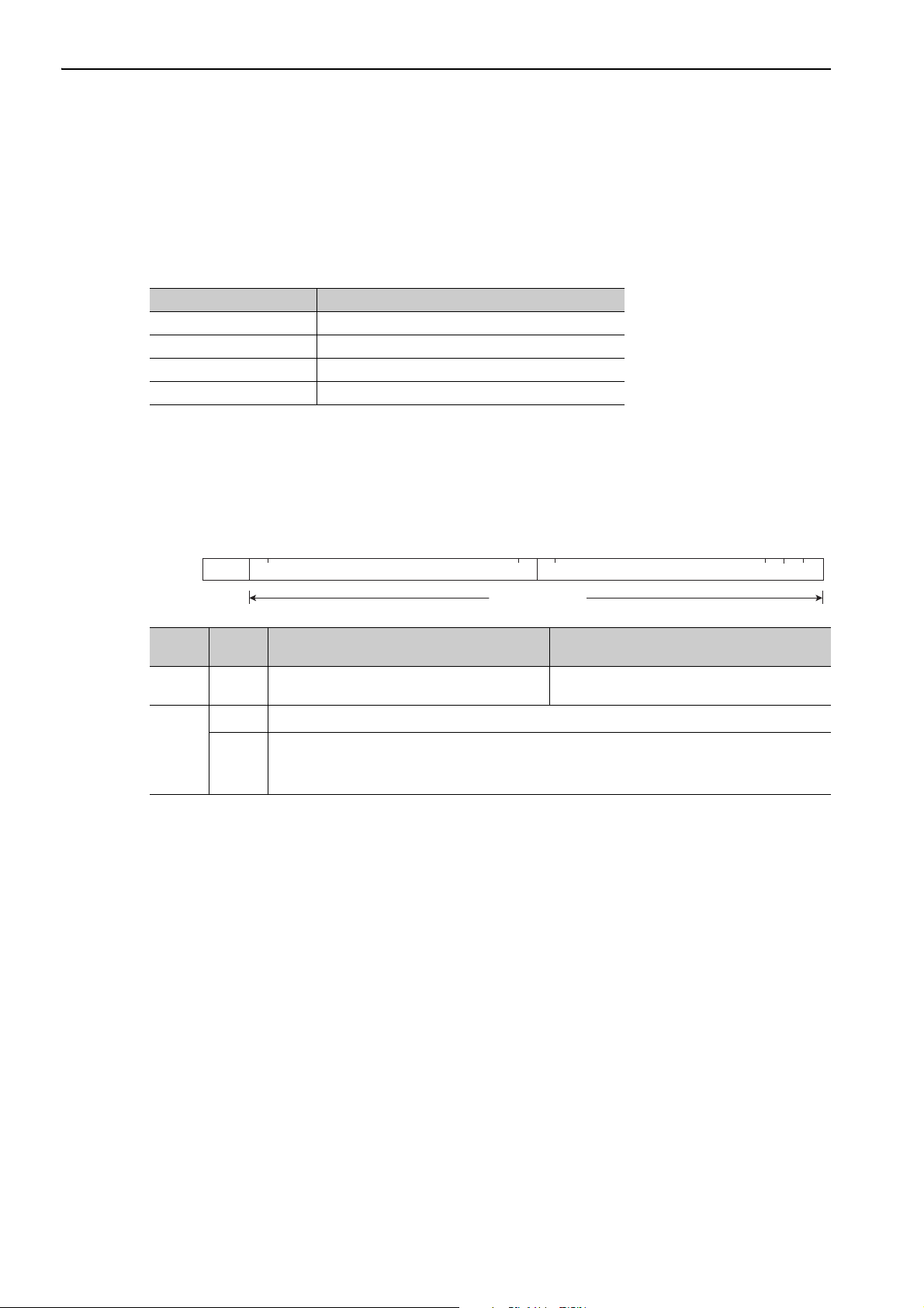
1.1.2 Frame Structure
A MECHATROLINK-II command is composed of a main command and a subcommand as shown below. It
can also be used only with a main command.
Classifi-
cation
Control
Field
Informa-
tion
Field
Byte Command Response
0 03H (Fixed) 01H (Fixed)
1 to 16 Used by main command.
Used by subcommands. The subcommands for servo drives use only 17th to 29th byte. Therefore,
17 to 31
only 17th to 29th byte are described in this manual.
Note: In some main commands, subcommand cannot be used.
The application layer interfaces with only the information field.
1-2
1
MECHATROLINK-II Commands
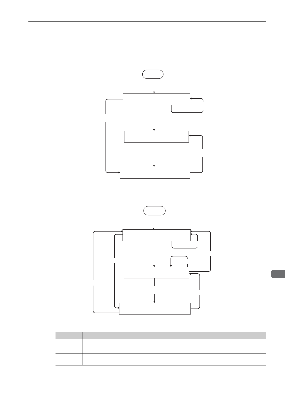
1.1.3 State Transition Diagram
P1/ Waits for connection establishment
P2/ Asynchronous communications state
P3/ Synchronous communications state
Sends CONNECT
(Asynchronous communications)
Sends SYNC_SET
Power ON
Start
Sends CONNECT
(Synchronous communications)
Communications
error
Communications
error
The primary (master) and secondary (slave) station state transitions are shown in the following diagrams.
Primary Station (Master Station) State Transition
1.1 MECHATROLINK-II Communications
Secondary Station (Slave Station) State Transition
Start
Power ON
P1/ Waits for connection establishment
Sends CONNECT
(Asynchronous communications)
Receives CONNECT
P2/ Asynchronous communications state
Receives DISCONNECT
Sends SYNC_SET
Phase Abbreviation Description
1 P1 Waiting for establishment of connection.
P3/ Synchronous communciations state
2 P2 Asynchronous communications enabled. Only asynchronous commands can be used.
3P3
Synchronous communications enabled. Both synchronous and asynchronous commands
can be used.
Communications
error
Receives DISCONNECT
Communications
error
Communications
error
1-3

1 MECHATROLINK-II Commands
1.1.4 Terminology
1.1.4 Terminology
This section defines the terminology used in this manual.
(1) Transmission Cycle and Communications Cycle
Transmission Cycle:
The transmission cycle is the cycle in the MAC (Media Access Control) layer. It is the communications cycle
for physically sending data to the transmission path.
The transmission cycle is unaffected by the services provided by the application layer.
Communications Cycle:
The communications cycle is the cycle for application layer. The communications cycle is set to an integral
multiple of the transmission cycle.
(2) Synchronization Classification
MECHATROLINK-II commands include both synchronous and asynchronous commands.
• Synchronous Commands (Classification S):
For commands of this type, commands are sent and response are received every communications cycle.
A response to a command that has been sent to a slave station is received at the next communications cycle.
The WDT (Watchdog Timer) in the frames are refreshed and checked every communications cycle. Synchronous commands can be used only during synchronous communications (Phase 3).
• Asynchronous Commands (Classification A):
For commands of this type, commands are sent asynchronously to the communications cycle.
Subsequent commands can be sent after confirming the completion of processing of the slave station that
received the command.
The WDT (Watchdog Timer) in the frames are not checked.
1-4

1
MECHATROLINK-II Commands
1.2 MECHATROLINK-II Command List
1.2.1 Main Commands (In command code order)
The MECHATROLINK-II main commands used for Σ-V series servo drives are listed below.
1.2 MECHATROLINK-II Command List
Command
Code
00H NOP Nothing is performed. 3.2.1
01H PRM_RD Reads the specified parameter. 3.2.13
02H PRM_WR Saves the specified parameter. 3.2.6
03H ID_RD Reads the device ID. 3.2.5
04H CONFIG Enables the current parameter settings. 3.2.8
05H ALM_RD Reads the current alarm or warning status, and the alarm history. 3.2.15
06H ALM_CLR Clears the current alarm or warning status, and the alarm history. 3.2.16
0DH SYNC_SET Starts synchronous communications. 3.2.4
0EH CONNECT Requests to establish a MECHATROLINK connection. 3.2.3
0FH DISCONNECT Requests to releases connection. 3.2.2
1CH PPRM_WR Saves the parameters in non-volatile memory. 3.2.7
20H POS_SET Sets the coordinates. 3.2.17
21H BRK_ON Turns the brake signal off and applies the holding brake. Appendix A
22H BRK_OFF Turns the brake signal on and release the holding brake. Appendix A
23H SENS_ON Turns the encoder power supply on, and gets the position data. 3.2.9
24H SENS_OFF Turns the encoder power supply off. 3.2.11
25H HOLD
28H LTMOD_ON Enables the position data latch by the external signal input. 4.2.2
29H LTMOD_OFF Disables the position data latch by the external signal input. 4.2.3
30H SMON Monitors the SERVOPACK status. 3.2.14
31H SV_ON Turns the servo of the motor on. 3.2.10
32H SV_OFF Turns the servo of the motor off. 3.2.12
34H INTERPOLATE Starts interpolation feeding. 4.2.4
35H POSING
36H FEED Starts constant speed feeding at the target speed (TSPD) 4.2.6
38H LATCH
39H EX_POSING
3AH ZRET Performs a homing. 4.2.9
3CH VELCTRL Controls speed. 4.2.10
3DH TRQCTRL Controls torque (force). 4.2.11
3EH ADJ Used to monitor and adjust data for maintenance. 3.2.18
3FH SVCTRL
Command Function Reference
From current motion status, performs a deceleration stop and positioning
according to the deceleration value set in the parameter.
Starts positioning to the target position (TPOS) at the target speed
(TSPD).
Performs interpolation feeding and latches the position using the specified
latch signal.
Moves toward the target position (TPOS) at the target speed (TSPD).
When a latch signal is input midway, positioning is performed according
to the final travel distance for external position specified in the parameter
from the latch signal input position.
Performs general-purpose servo control. This command is compatible
with MECHATROLINK version 1.0 and earlier.
Appendix B
4.2.1
4.2.5
4.2.7
4.2.8
1-5

1 MECHATROLINK-II Commands
1.2.2 Subcommands (In command code order)
1.2.2 Subcommands (In command code order)
The MECHATROLINK-II subcommands used for Σ-V series servo drives are listed below.
Command
Code
00H NOP Same function as of the main command NOP 6.2.1
01H PRM_RD Same function as of the main command PRM_RD 6.2.2
02H PRM_WR Same function as of the main command PRM_WR 6.2.3
05H ALM_RD Same function as of the main command ALM_RD 6.2.4
1CH PPRM_WR Same function as of the main command PPRM_WR 6.2.5
28H LTMOD_ON Same function as of the main command LTMOD_ON 6.2.6
29H LTMOD_OFF Same function as of the main command LTMOD_OFF 6.2.7
30H SMON Same function as of the main command SMON 6.2.8
Command Function Reference
1-6

1.2 MECHATROLINK-II Command List
1
MECHATROLINK-II Commands
1.2.3 Combination of MECHATROLINK-II Main Commands and Subcommands
Subcommands can be used by combining as listed below.
Subcommand
CODE Main Command
00 NOP √√√√√√√√
01 PRM_RD √
02 PRM_WR √
03 ID_RD √√√√√√√√
04 CONFIG √
05 ALM_RD √
06 ALM_CLR √
0D SYNC_SET √
0E CONNECT √
0F DISCONNECT √
1C PPRM_WR √
20 POS_SET √
21 BRK_ON √
22 BRK_OFF √
23 SENS_ON √
24 SENS_OFF √
25 HOLD √√√√√√√√
28 LTMOD_ON √
29 LTMOD_OFF √
30 SMON √√√√√√√√
31 SV_ON √√√√√√√√
32 SV_OFF √√√√√√√√
34 INTERPOLATE √√√√√√√√
35 POSING √√√√√√√√
36 FEED √√√√√√√√
38 LATCH √√√√√
39 EX_POSING √√√√√
3A ZRET √√√√√
3C VELCTRL √√√√√√√√
3D TRQCTRL √√√√√√√√
3E ADJ √
3F SVCTRL √√√√√
NOP PRM_RD PRM_WR ALM_RD
× × × × × ×√
× × × × × ×√
× × × × × ×√
× × × × × ×√
× × × × × ×√
× × × × × ×√
× × × × × × ×
× × × × × × ×
× × × × × ×√
× × × × × ×√
× × × × × ×√
× × × × × ×√
× × × × × ×√
× × × × × ×√
× × × × × ×√
× × × × × ×√
× × × × × ×√
PPRM_WRLTMO D_ONLTM OD_
OFF
× ×√
× ×√
× ×√
× ×√
SMON
Note: √: Can be combined, ×: Cannot be combined
1-7
1 MECHATROLINK-II Commands
Transmission cycle
Master sends
Received
312.5 μs until the motor starts running
Slave sends
Command
Sent
Response
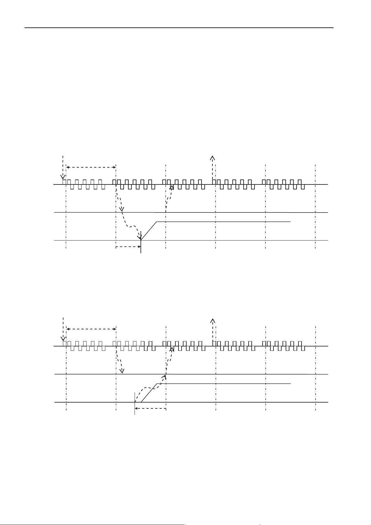
1.3.1 Command Data Execution Timing
1.3 Command and Response Timing
This section describes command execution timing at a slave station and monitored data input timing at the
master station.
These timings are constant, regardless of the transmission cycle and communications cycle.
1.3.1 Command Data Execution Timing
Motion commands (such as POSING and INTERPOLATE) and the OPTION in the command data field are
executed 312.5 μs after they are received.
1.3.2 Monitored Data Input Timing
The monitor, I/O, and status data are the data of 312.5 μs before the response is sent.
Command
Transmission cycle
Master sent
Slave sent
Received
Position and signal data 312.5 μs before
Sent
Response
1-8

1
MECHATROLINK-II Commands
1.4 Data Order
Data in MECHATROLINK-II commands and responses is stored in little endian byte order.
For example, 4-byte data “0x1234ABCD” in hexadecimal is stored from the least significant byte as shown
below.
Byte Data
1CD
2AB
334
412
1.4 Data Order
1-9

2
Operation Sequence
2
Operation Sequence
This chapter describes basic operation sequences through MECHATROLINK-II communications.
2.1 Preparing for Operation . . . . . . . . . . . . . . . . . . . . . . . . . . . . . . . . . . . . . .2-2
2.1.1 Setting MECHATROLINK-II Communications . . . . . . . . . . . . . . . . . . . . . . . . . . . . . . 2-2
2.1.2 Checking the Communications Status . . . . . . . . . . . . . . . . . . . . . . . . . . . . . . . . . . . . 2-8
2.2 Operation Sequence for Managing Parameters Using a Controller . . . . .2-9
2.3 Operation Sequence for Managing Parameters Using a SERVOPACK . 2-10
2.3.1 Setup Sequence . . . . . . . . . . . . . . . . . . . . . . . . . . . . . . . . . . . . . . . . . . . . . . . . . . . . 2-10
2.3.2 Ordinary Operation Sequence . . . . . . . . . . . . . . . . . . . . . . . . . . . . . . . . . . . . . . . . . 2-10
2.4 Specific Operation Sequences . . . . . . . . . . . . . . . . . . . . . . . . . . . . . . . . 2-11
2.4.1 Operation Sequence When Turning the Servo ON . . . . . . . . . . . . . . . . . . . . . . . . . . 2-11
2.4.2 Operation Sequence When OT (Overtravel Limit Switch) Signal Is Input . . . . . . . . . 2-11
2.4.3 Operation Sequence at Emergency Stop (Main Circuit OFF) . . . . . . . . . . . . . . . . . . 2-11
2.4.4 Operation Sequence When a Safety Signal is Input . . . . . . . . . . . . . . . . . . . . . . . . . 2-12
2.4.5 Operation Sequence at Occurrence of Alarm . . . . . . . . . . . . . . . . . . . . . . . . . . . . . . 2-13
2.4.6 When Motion Command Is Interrupted and Servomotor Is in Position . . . . . . . . . . . 2-13
2.5 Setting the Origin Before Starting Operation . . . . . . . . . . . . . . . . . . . . . .2-14
2.5.1 When Using an Incremental Encoder . . . . . . . . . . . . . . . . . . . . . . . . . . . . . . . . . . . . 2-14
2.5.2 When Using an Absolute Encoder . . . . . . . . . . . . . . . . . . . . . . . . . . . . . . . . . . . . . . 2-14
2-1
2 Operation Sequence
ON
OFF
SW2 (factory settings)
SW1 (factory setting)
1234
0
F1
E2
D3
8
4C
B5
A6
97
2.1.1 Setting MECHATROLINK-II Communications
2.1 Preparing for Operation
This section describes how to set communications specifications before starting communications, and how to
confirm the communications status.
2.1.1 Setting MECHATROLINK-II Communications
(1) When the Σ-V Series SERVOPACKs (SGDV-A11, -A15, -D11,
-D15, -F11, -F15) are Used
The rotary switch (SW1) and DIP switch (SW2), which are located near the top under the front cover of the
SERVOPACK, are used as shown below to set the MECHATROLINK-II communications specifications.
Setting the Communications Specifications
Set the communications specifications using the DIP switch (SW2).
SW2 Function Setting Description Factory setting
Pin 1 Sets the baud rate.
Sets the number of
Pin 2
transmission bytes.
Pin 3 Sets the station address.
Pin 4 Reserved. (Do not change.) OFF – OFF
• When connecting to a MECHATROLINK-I network, turn OFF pins 1 and 2.
• When using a MECHATROLINK-I network (Baud rate: 4 Mbps), the settings for the
number of transmission bytes is disabled and the number of transmission bytes is
always 17.
OFF 4 Mbps (MECHATROLINK-I)
ON 10 Mbps (MECHATROLINK-II)
OFF 17 bytes
ON 32 bytes
OFF Station address = 40H + SW1
ON Station address = 50H + SW1
ON
ON
OFF
2-2

2.1 Preparing for Operation
2
Operation Sequence
Setting the Station Address
The following table lists the possible settings of the rotary switch (SW1) and the DIP switch (SW2) that can be
combined to form a station address.
The factory setting for the station address is 41H (Bit 3 of SW2 = OFF, SW1 = 1)
Bit 3 of SW2 SW1 Station Address Bit 3 of SW2 SW1 Station Address
OFF 0 Disabled ON 0 50H
OFF 1 41H ON 1 51H
OFF 2 42H ON 2 52H
OFF 3 43H ON 3 53H
OFF 4 44H ON 4 54H
OFF 5 45H ON 5 55H
OFF 6 46H ON 6 56H
OFF 7 47H ON 7 57H
OFF 8 48H ON 8 58H
OFF 9 49H ON 9 59H
OFF A 4AH ON A 5AH
OFF B 4BH ON B 5BH
OFF C 4CH ON C 5CH
OFF D 4DH ON D 5DH
OFF E 4EH ON E 5EH
OFF F 4FH ON F 5FH
Turn the power OFF and then ON again to validate the new settings.
2-3
2 Operation Sequence
OFF
ON
SW2 (factory setting)
1234
OFF
ON
SW1 (factory setting)
1234
2.1.1 Setting MECHATROLINK-II Communications
(2) When the DC Power Input Σ-V Series SERVOPACKs (SGDV-E11) are Used
The DIP switches (SW1 and SW2), which are on the front cover of the SERVOPACK, are used as shown
below to set the MECHATROLINK-II communications specifications.
Setting the Communications Specifications
Set the communications specifications using the DIP switch (SW2).
SW2 Function Setting Description Factory setting
Pin 1 Sets the baud rate.
Sets the number of
Pin 2
transmission bytes.
Pin 3 Sets the station address.
Pin 4 Reserved. (Do not change.) OFF – OFF
OFF 4 Mbps (MECHATROLINK-I)
ON 10 Mbps (MECHATROLINK-II)
OFF 17 bytes
ON 32 bytes
OFF Station address = 40H + SW1
ON Station address = 50H + SW1
ON
ON
OFF
• When connecting to a MECHATROLINK-I network, turn OFF pins 1 and 2.
• When using a MECHATROLINK-I network (Baud rate: 4 Mbps), the settings for the
number of transmission bytes is disabled and the number of transmission bytes is
always 17.
2-4

2.1 Preparing for Operation
2
Operation Sequence
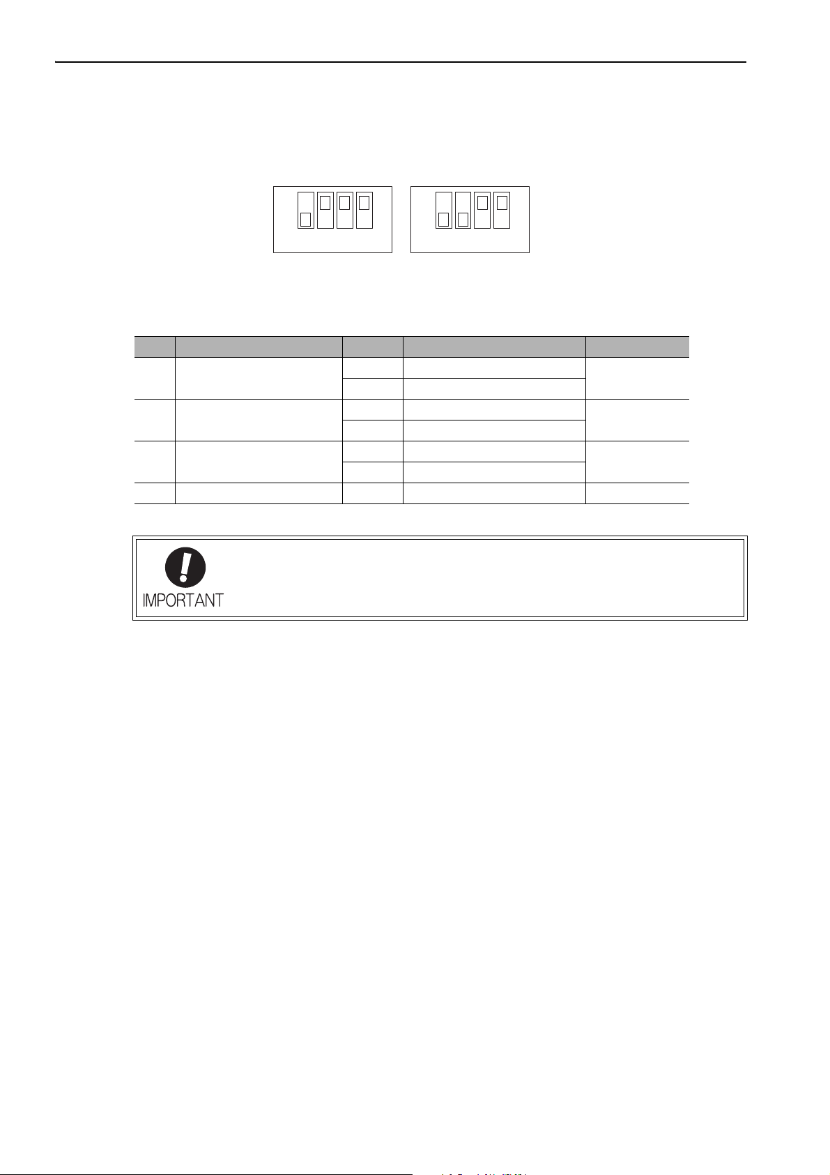
Setting the Station Address
The following table lists the possible settings of the DIP switches (SW1 and SW2) that can be combined to
form a station address.
The factory setting for the station address is 41H (Bit 3 of SW2 = OFF, Bit 1 of SW1 = ON, Bit 2 of SW1 =
OFF, Bit 3 of SW1 = OFF, Bit 4 of SW1 = OFF).
Setting
Bit 3 of SW2 Bit 1 of SW1 Bit 2 of SW1 Bit 3 of SW1 Bit 4 of SW1
OFF OFF OFF OFF OFF Disabled
OFF ON OFF OFF OFF 41H
OFF OFF ON OFF OFF 42H
OFF ON ON OFF OFF 43H
OFF OFF OFF ON OFF 44H
OFF ON OFF ON OFF 45H
OFF OFF ON ON OFF 46H
OFFONONONOFF 47H
OFF OFF OFF OFF ON 48H
OFF ON OFF OFF ON 49H
OFF OFF ON OFF ON 4AH
OFF ON ON OFF ON 4BH
OFF OFF OFF ON ON 4CH
OFF ON OFF ON ON 4DH
OFF OFF ON ON ON 4EH
OFFONONONON 4FH
ON OFF OFF OFF OFF 50H
ON ON OFF OFF OFF 51H
ON OFF ON OFF OFF 52H
ON ON ON OFF OFF 53H
ON OFF OFF ON OFF 54H
ON ON OFF ON OFF 55H
ON OFF ON ON OFF 56H
ON ON ON ON OFF 57H
ON OFF OFF OFF ON 58H
ON ON OFF OFF ON 59H
ON OFF ON OFF ON 5AH
ON ON ON OFF ON 5BH
ON OFF OFF ON ON 5CH
ON ON OFF ON ON 5DH
ON OFF ON ON ON 5EH
ON ON ON ON ON 5FH
Station Address
Turn the power OFF and then ON again to validate the new settings.
2-5
2 Operation Sequence
4
3
5
2
6
1
7
C
8
0
F
9
E
A
D
B
ON
OFF
1 234
S3
S2
2.1.1 Setting MECHATROLINK-II Communications
(3) When the Large-Capacity Σ-V Series SERVOPACKs (SGDV-H11,
-J11) are Used
The rotary switch (S2) and DIP switch (S3), which are located near the top under the plastic cover of the SERVOPACK, are used as shown below to set the MECHATROLINK-II communications specifications.
Setting the Communications Specifications
Set the communications specifications using the DIP switch (S3).
S3 Function Setting Description Factory setting
Pin 1 Sets the baud rate.
Sets the number of
Pin 2
transmission bytes.
Pin 3 Sets the station address.
Pin 4 Reserved. (Do not change.) OFF – OFF
OFF 4 Mbps (MECHATROLINK-I)
ON 10 Mbps (MECHATROLINK-II)
OFF 17 bytes
ON 32 bytes
OFF Station address = 40H + S2
ON Station address = 50H + S2
ON
ON
OFF
• When connecting to a MECHATROLINK-I network, turn OFF pins 1 and 2.
• When using a MECHATROLINK-I network (Baud rate: 4 Mbps), the settings for the
number of transmission bytes is disabled and the number of transmission bytes is
always 17.
2-6
2.1 Preparing for Operation
2
Operation Sequence
Setting the Station Address
The following table lists the possible settings of the rotary switch (S2) and the DIP switch (S3) that can be
combined to form a station address.
The factory setting for the station address is 41H (Bit 3 of S3 = OFF, S2 = 1)
Bit 3 of S3 S2 Station Address Bit 3 of S3 S2 Station Address
OFF 0 Disabled ON 0 50H
OFF 1 41H ON 1 51H
OFF 2 42H ON 2 52H
OFF 3 43H ON 3 53H
OFF 4 44H ON 4 54H
OFF 5 45H ON 5 55H
OFF 6 46H ON 6 56H
OFF 7 47H ON 7 57H
OFF 8 48H ON 8 58H
OFF 9 49H ON 9 59H
OFF A 4AH ON A 5AH
OFF B 4BH ON B 5BH
OFF C 4CH ON C 5CH
OFF D 4DH ON D 5DH
OFF E 4EH ON E 5EH
OFF F 4FH ON F 5FH
Turn the power OFF and then ON again to validate the new settings.
2-7
2 Operation Sequence
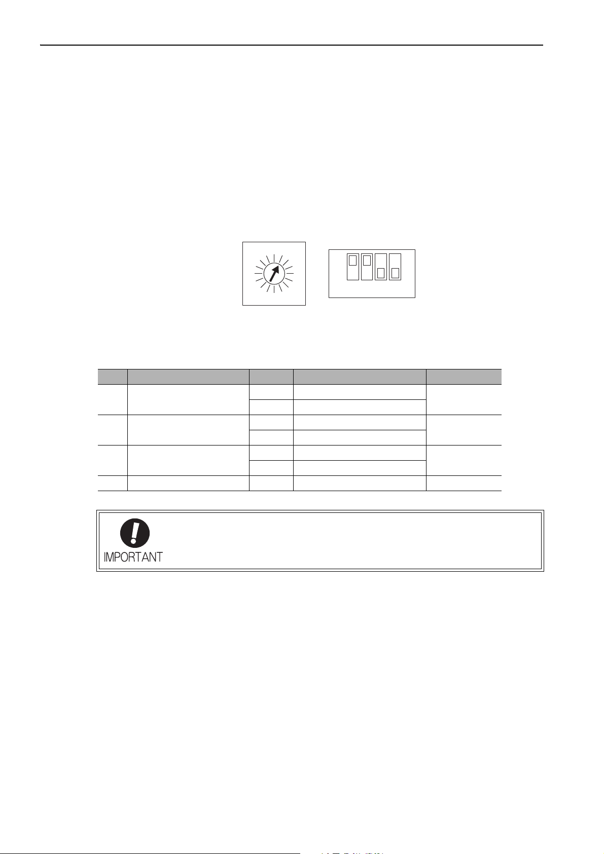
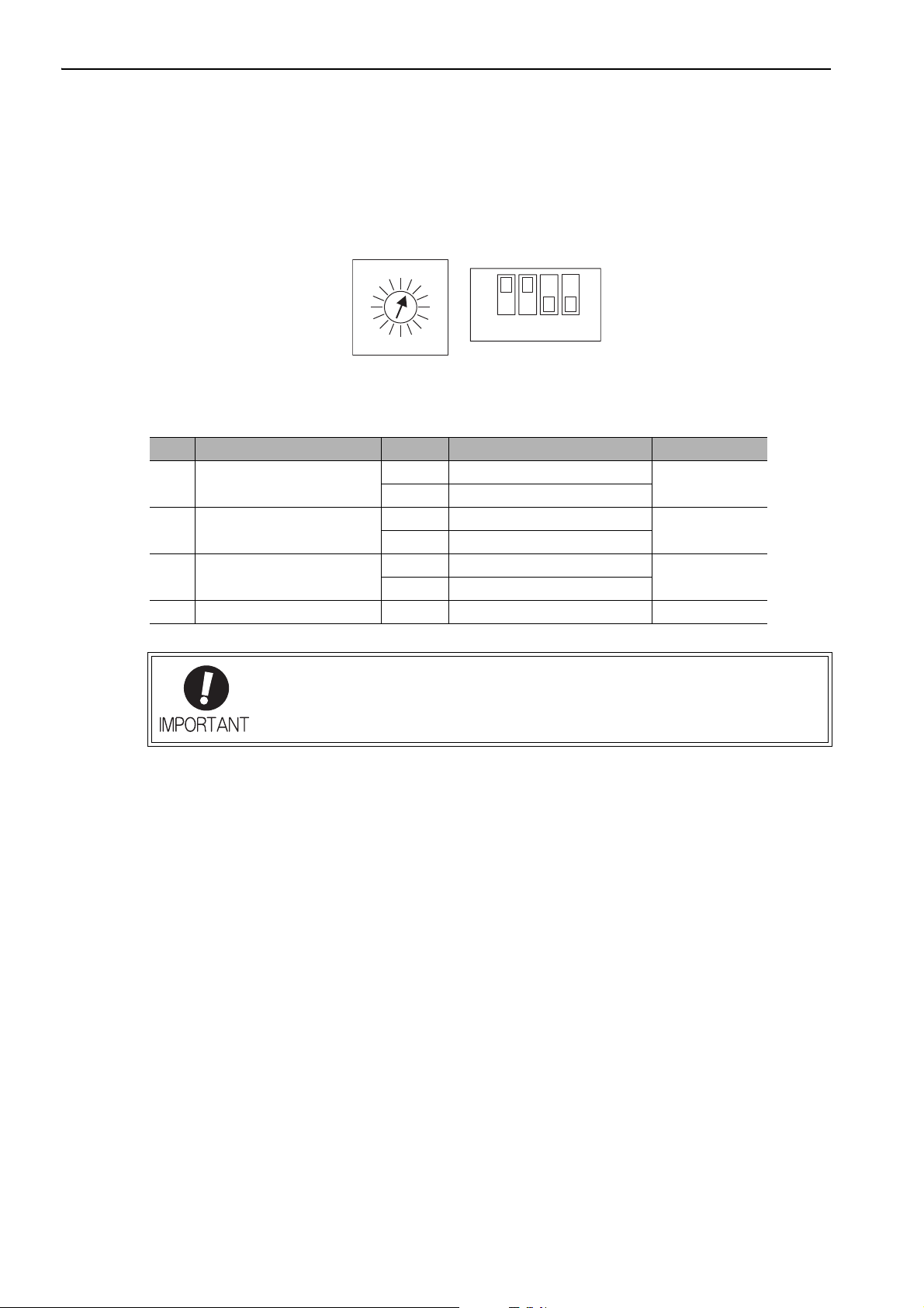
When lit: CONNECT execution completed
When unlit: CONNECT execution not completed
When lit: During data link communications.
When unlit: Communications not established.
2.1.2 Checking the Communications Status
2.1.2 Checking the Communications Status
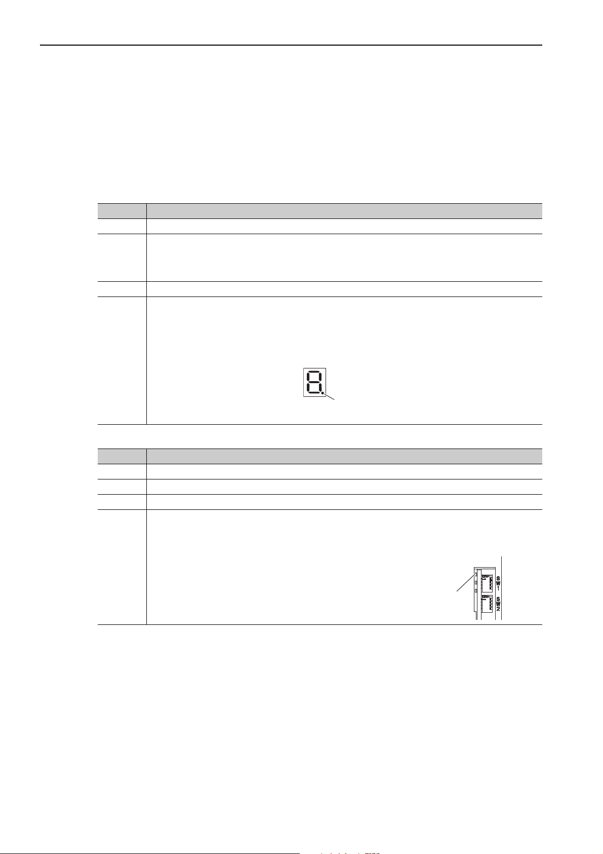
Turn ON the control and main circuit power supplies and use the following procedure to confirm that the SERVOPACK is ready for communications.
(1) Operation Procedure
When the Σ-V Series SERVOPACKs (SGDV-A11, -A15, -D11,
-D15, -F11, -F15) or the Large-Capacity Σ-V Series SERVOPACKs
(SGDV-H11, -J11) are Used
Procedure Operation
1 Confirm that the wiring is correctly made.
Turn ON the SERVOPACK control and main circuit power supplies.
When the control power is being normally supplied to the SERVOPACK, POWER LED on the SERVO-
2
PACK is lit.
When the main circuit power supply is ON, CHARGE is lit.
3 Turn ON the controller power supply and start MECHATROLINK communications.
Check the communications status.
When communications in the data link layer have started, COM LED on the SERVOPACK is lit.
Note: If COM LED is not lit, check the communications settings of SW1, SW2, and the controller, and then
turn the power supplies OFF and ON again.
When the MECHATROLINK-II connection in the application layer is established, the 7-segment LED indicates the completion of CONNECT execution as shown below.
4
When the DC Power Input Σ-V Series SERVOPACKs (SGDV-E11) are Used
Procedure Operation
1 Confirm that the wiring is correctly made.
2 Turn ON the SERVOPACK control and main circuit power supplies.
3 Turn ON the controller power supply and start MECHATROLINK communications.
Check the communications status.
When communications in the data link layer have started, COM LED on the SERVOPACK is lit.
Note: If COM LED is not lit, check the communications settings of SW1, SW2, and the controller, and then
turn the power supplies OFF and ON again.
4
2-8

2.2 Operation Sequence for Managing Parameters Using a Controller
2
Operation Sequence
2.2 Operation Sequence for Managing Parameters Using a
Controller
When the parameters are managed by a controller, the parameters are automatically transmitted from the controller to the SERVOPACK when the power is turned ON. Therefore, the settings of SERVOPACK do not
need to be changed when the SERVOPACK is replaced.
Procedure Operation Command to Send
1 Turn on the control and main circuit power supplies. NOP
2 Reset the previous communications status.
3 Establish communications connection and starts WDT count. CONNECT
4 Check information such as device ID. ID_RD
5 Get device setting data such as parameters. PRM_RD, ADJ
6 Set the parameters required for device. PRM_WR
7 Enable the parameter settings (Setup). CONFIG
8 Turn the encoder power supply to the position data. SENS_ON
9 Turn the servo on. SV_ON
10 Start operation. –
11 Turn the servo off. SV_OFF
12 Disconnect the communications connection. DISCONNECT
13 Turn the control and main circuit power supplies. –
DISCONNECT
*
∗ If the connection cannot be released normally, send DISCONNECT command for 2 or more communications cycles,
and then send CONNECT command.
2-9

2 Operation Sequence
2.3.1 Setup Sequence
2.3 Operation Sequence for Managing Parameters Using a SERVOPACK
To manage the parameters by using SERVOPACK’s non-volatile memory, save the parameters in the non-volatile memory at setup and use an ordinary operation sequence.
2.3.1 Setup Sequence
Procedure Operation Command to Send
1 Turn on the control and main circuit power supply. NOP
2 Reset the previous communications status.
3 Establish communications connection and start WDT count. CONNECT
4 Check information such as device ID. ID_RD
5 Get device setting data such as parameters. PRM_RD, ADJ
Save the parameters required for device in the non-volatile
6
memory.
7 Disconnect the communications connection. DISCONNECT
8 Turn off the control and main circuit power supplies. –
DISCONNECT
PPRM_WR
Note: Do not use PRM_WR.
*
∗ If the connection cannot be released normally, send a DISCONNECT command for 2 or more communications cycles,
and then send a CONNECT command.
2.3.2 Ordinary Operation Sequence
Procedure Operation Command to Send
1 Turn on the control and main circuit power supplies. NOP
2 Reset the previous communications status.
3 Establish communications connection and start WDT count. CONNECT
4 Check information such as device ID. ID_RD
5 Get device setting data such as parameters. PRM_RD, ADJ
6 Turn on the encoder power supply to get the position data. SENS_ON
7 Turn the servo on. SV_ON
8 Start operation. POSING, INTERPOLATE, etc.
9 Turn the servo off. SV_OFF
10 Disconnect the communications connection. DISCONNECT
11 Turn off the control and main circuit power supplies. –
∗ If the connection cannot be released normally, send a DISCONNECT command for 2 or more communications cycles,
and then send a CONNECT command.
DISCONNECT
*
2-10

2.4 Specific Operation Sequences
2
Operation Sequence
2.4 Specific Operation Sequences
This section describes operations that use commands in specific sequences.
2.4.1 Operation Sequence When Turning the Servo ON
Motor control using a host controller is performed using motion commands only during Servo ON (motor
power ON).
While the SERVOPACK is in Servo OFF status (while current to the motor is interrupted), the SERVOPACK
manages position data so that the reference coordinate system (POS, MPOS) and the feedback coordinate system (APOS) are equal. For correct execution of motion commands, therefore, it is necessary to use the SMON
(Status Monitoring) command after the SERVOPACK status changes to Servo ON, to read the servo reference
coordinates (POS) and send an appropriate reference position.
Confirm the following bit status before sending the SV_ON command:
STATUS field: PON = 1 and ALM = 0
IO Monitor field: HBB = 0
2.4.2 Operation Sequence When OT (Overtravel Limit Switch) Signal Is Input
When an OT signal is input, the SERVOPACK prohibits the motor from rotating in the way specified in the
parameter Pn001. The motor continues to be controlled by the SERVOPACK while its rotation is prohibited.
When an OT signal is input, use the following procedure to process the OT signal.
Procedure Operation
Monitor OT signals (P_OT and N_OT of IO Monitor field). When an OT signal is input, send an appropriate stop command:
While an interpolation command (INTERPOLATE, LATCH) is being executed: Leave the interpolation
command as it is and stop updating the interpolation position. Or, send a HOLD command and SMON
1
command.
While a move command (such as POSING) other than interpolation commands is being executed: Send a
HOLD command.
Check the output completion flag DEN. If DEN = 1, the SERVOPACK completed the OT processing.
2
At the same time, check the flag PSET. If PSET = 1, the motor is completely stopped.
Keep the command used in procedure 1 active until both of the above flags are set to 1.
3 Read out the current reference position (POS) and use it as the start position for retraction processing.
Use a move command such as POSING or INTERPOLATE for retraction processing. Continue to use this
4
command until the retraction is finished. If the move command ends without finishing the retraction, restart
the move command continuously from the last target position.
Note 1. When an OT signal is input during execution of motion command ZRET or EX_POSING, the execution of the
command will be cancelled. For retraction, always send a stop command described in procedure 1 first, and then
send a retraction command (move command).
2. In case of OT ON (P-OT or N-OT of IO_MON field = 1) or Software-Limit ON (P_SOT or N_SOT of STATUS
field = 1), the motor may not reach the target position that the host controller specified. Make sure that the axis
has stopped at a safe position by confirming the feedback position (APOS).
The host controller may not be able to monitor a brief change in the P-OT or N-OT signal
to P-OT=1 or N-OT=1. Proper selection, installation and wiring in the limit switch is
required to avoid chattering and malfunctions in the OT signal.
2.4.3 Operation Sequence at Emergency Stop (Main Circuit OFF)
After confirming that SV_ON or PON bit in the response data STATUS field is OFF (= 0), send an SV_OFF
command.
During emergency stop, always monitor the SERVOPACK status using a command such as the SMON (Status
Monitoring) command.
2-11
2 Operation Sequence
BB status
(baseblocked)
RUN status
HWBB status
(hard wire baseblocked)
/HWBB1
/HWBB2
STATUS
field
SVON
RUN status
SERVOPACK
status
ON
(Does not request HWBB function)
ON
(Does not request HWBB function)
OFF
(Request HWBB function)
1
01
M-II
command
IO Monitor
field
HBB
10
0
Motion command,
etc.
SV_OFF
command, etc.
SV_ON
command, etc.
BB status
(baseblocked)
SV_OFF
command
BB status
(baseblocked)
RUN status
HWBB status
(hard wire baseblocked)
RUN status
10 1
100
/HWBB1
/HWBB2
STATUS
field
SVON
SERVOPACK
status
M-II
command
IO Monitor
field
HBB
Motion command, etc. SV_OFF command, etc.
SV_ON
command, etc.
ON
(Does not request HWBB function)
ON
(Does not request HWBB function)
OFF
(Request HWBB function)
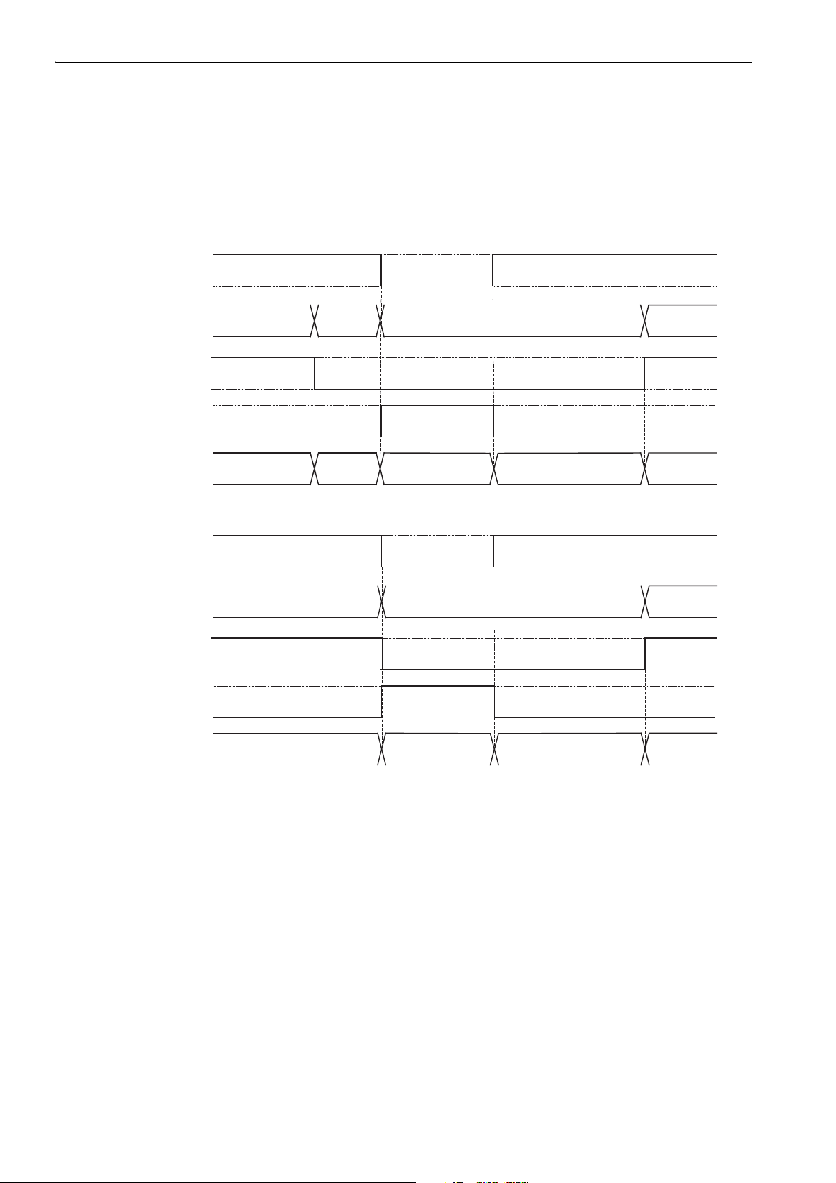
2.4.4 Operation Sequence When a Safety Signal is Input
2.4.4 Operation Sequence When a Safety Signal is Input
When an HWBB1 or HWBB2 signal is input while the motor is being operated, current to the motor will be
forcibly stopped, and the motor will be stopped according to the setting of the 1st digit of parameter Pn001.
Note: The safety function cannot be used with DC power input Σ-V series SERVOPACKs (SGDV-E11).
[When an HWBB signal is input after the SERVOPACK stops powering the motor]
[When an HWBB signal is input while the SERVOPACK is powering the motor]
When an HWBB Signal is Input
Monitor the HWBB input signal and SCM output signal status, or HBB signal status in IO Monitor field. If a
forced stop status is detected, send a command such as SV_OFF to stop the motor.
Restoration from Stop Status
Reset the HWBB1 or HWBB2 signal, and then send a command other than SV_ON, such as SV_OFF. Then,
restore the controller and system. When the controller and system are restored, turn the servo ON using the
operation sequence to turn the servo ON.
2-12
Note 1. If the SERVOPACK enters HWBB status while sending an SV_ON command, reset the /HWBB1 or /HWBB2
signal and then send a command other than SV_ON, such as SV_OFF. Then, send the SV_ON command again to
restore the normal operation status.
2. If the SERVOPACK enters HWBB status during execution of an SV_OFF, INTERPOLATE, LATCH, POSING,
FEED, EX_POSING, or ZRET command, a command warning will occur since the SERVOPACK status changes
to Servo OFF status. Execute the Clear Alarm or Warning (ALM_CLR) command to restore normal operation.

2.4 Specific Operation Sequences
2
Operation Sequence
2.4.5 Operation Sequence at Occurrence of Alarm
When the ALM bit in STATUS field of response turns on (= 1), send SV_OFF command. Use ALM_RD command to check the alarm occurrence status.
To clear the alarm status, send ALM_CLR command after removing the cause of alarm. However, the alarms
that require turning the power supply off and then on again to clear the alarm status, sending ALM_CLR command will not clear the alarm status.
If a communications alarm A.E5or A.E6 occurs, send ALM_CLR command to reset the alarm and then
send SYNC_SET command.
2.4.6 When Motion Command Is Interrupted and Servomotor Is in Position
During execution of a Motion command, any one of the following statuses on the SERVOPACK will cause
interruption of the motion command and an in-position status of PSET=1.
• Alarm occurrence (ALM of STATUS field =1) causes Servo-Off (SVON of STATUS field =0).
• Main power supply OFF (PON of STATUS field =0) causes Servo-Off (SVON of STATUS field =0).
• OT ON (P-OT or N-OT of IO_MON field = 1) or Software-Limit ON (P_SOT or N_SOT of STATUS field
= 1) causes the motor to stop.
Even when PSET is 1 in these cases, the motor may not reach the target position that the host controller specified. Obtain the feedback position (APOS) to make sure that the axis has stopped at a safe position.
The host controller may not be able to monitor a brief change in the P-OT or N-OT signal
to P-OT=1 or N-OT=1. Proper selection, installation and wiring in the limit switch is
required to avoid chattering and malfunctions in the OT signal.
2-13
 Loading...