

Page 1
1/144
Part Number 194801-1CD
Revision: 1
MOTOMAN-HC10DTP
Dust-Proof/Drip-Proof Specification/
MOTOMAN-HC10DTFP
Quick Start Guide
Using the Smart Pendant
• Manipulator Type: YR-1-06VXCP10-B00
(Built-In Air Hoses, Ethernet and I/O Cables Specification)
YR-1-06VXCP10-F00
(Built-In Air Hoses, Ethernet and I/O Cables Specification)
• Applicable Robot Controllers: YRC1000/YRC1000micro
• Smart Pendant Type: JZRCR-APP30-1
MANUAL NO. HW2480573
Unpacking and
Checking the Product
Transportation and
Installation
Connecting
the Robot Controller
Turning ON the Robot Controller
Power Supplies
Controlling the Manipulator
Mounting and Wiring
the Hand
Settings
Programming
1
1
2
3
4
5
6
7
8
Page 2

2
HW2480573
2/144
Page 3

Table of Contents
HW2480573
3/144
i. Before Using the Product. . . . . . . . . . . . . . . . . . . . . . . . . . . . . . . . . . . . . . . . . 7
i.1 Introduction to This Manual . . . . . . . . . . . . . . . . . . . . . . . . . . . . . . . . . . . . . . . . . . . . 8
i.1.1 Intended Audience . . . . . . . . . . . . . . . . . . . . . . . . . . . . . . . . . . . . . . . . . . . . . . . . . . . . . . . . . . . . . . . . . . 8
i.1.2 Precautions for Safely Using a Collaborative Robot . . . . . . . . . . . . . . . . . . . . . . . . . . . . . . . . . . . . . . . . 8
i.1.3 Applicable Products . . . . . . . . . . . . . . . . . . . . . . . . . . . . . . . . . . . . . . . . . . . . . . . . . . . . . . . . . . . . . . . . . 9
i.1.4 Related Manuals . . . . . . . . . . . . . . . . . . . . . . . . . . . . . . . . . . . . . . . . . . . . . . . . . . . . . . . . . . . . . . . . . . . . 9
i.2 Notes for Safe Operation . . . . . . . . . . . . . . . . . . . . . . . . . . . . . . . . . . . . . . . . . . . . . .11
i.2.1 Safety Information . . . . . . . . . . . . . . . . . . . . . . . . . . . . . . . . . . . . . . . . . . . . . . . . . . . . . . . . . . . . . . . . . . .11
i.2.2 Visual Aids . . . . . . . . . . . . . . . . . . . . . . . . . . . . . . . . . . . . . . . . . . . . . . . . . . . . . . . . . . . . . . . . . . . . . . . . .11
i.2.3 General Precautions . . . . . . . . . . . . . . . . . . . . . . . . . . . . . . . . . . . . . . . . . . . . . . . . . . . . . . . . . . . . . . . . 12
i.3 Using This Manual . . . . . . . . . . . . . . . . . . . . . . . . . . . . . . . . . . . . . . . . . . . . . . . . . . 13
i.3.1 Terms . . . . . . . . . . . . . . . . . . . . . . . . . . . . . . . . . . . . . . . . . . . . . . . . . . . . . . . . . . . . . . . . . . . . . . . . . . . . 13
i.3.2 Trademarks . . . . . . . . . . . . . . . . . . . . . . . . . . . . . . . . . . . . . . . . . . . . . . . . . . . . . . . . . . . . . . . . . . . . . . . 13
1. Unpacking and Checking the Product. . . . . . . . . . . . . . . . . . . . . . . . . . . . . . 15
1.1 Unpacking the Shipping Crate . . . . . . . . . . . . . . . . . . . . . . . . . . . . . . . . . . . . . . . . 16
1.2 Checking the Received Products . . . . . . . . . . . . . . . . . . . . . . . . . . . . . . . . . . . . . . 17
1.2.1 Components in a Basic Robot System . . . . . . . . . . . . . . . . . . . . . . . . . . . . . . . . . . . . . . . . . . . . . . . . . 17
1.2.2 Manipulator Accessories. . . . . . . . . . . . . . . . . . . . . . . . . . . . . . . . . . . . . . . . . . . . . . . . . . . . . . . . . . . . . 18
1.2.3 YRC1000 Robot Controller Accessories . . . . . . . . . . . . . . . . . . . . . . . . . . . . . . . . . . . . . . . . . . . . . . . . 18
1.2.4 YRC1000micro Robot Controller Accessories . . . . . . . . . . . . . . . . . . . . . . . . . . . . . . . . . . . . . . . . . . . 19
1.2.5 Verifying the Order Numbers . . . . . . . . . . . . . . . . . . . . . . . . . . . . . . . . . . . . . . . . . . . . . . . . . . . . . . . . . 19
2. Transportation and Installation . . . . . . . . . . . . . . . . . . . . . . . . . . . . . . . . . . . 21
2.1 Transporting the Manipulator . . . . . . . . . . . . . . . . . . . . . . . . . . . . . . . . . . . . . . . . . 22
2.2 Installing the Manipulator . . . . . . . . . . . . . . . . . . . . . . . . . . . . . . . . . . . . . . . . . . . . 25
2.2.1 Required Items . . . . . . . . . . . . . . . . . . . . . . . . . . . . . . . . . . . . . . . . . . . . . . . . . . . . . . . . . . . . . . . . . . . . 25
2.2.2 Strength of the Installation Surface . . . . . . . . . . . . . . . . . . . . . . . . . . . . . . . . . . . . . . . . . . . . . . . . . . . . 25
2.2.3 Fixing the Manipulator to the Floor . . . . . . . . . . . . . . . . . . . . . . . . . . . . . . . . . . . . . . . . . . . . . . . . . . . . . 26
2.2.4 Grounding the Manipulator . . . . . . . . . . . . . . . . . . . . . . . . . . . . . . . . . . . . . . . . . . . . . . . . . . . . . . . . . . . 27
3
Page 4

2.3 Transporting the YRC1000 Robot Controller. . . . . . . . . . . . . . . . . . . . . . . . . . . . . . 28
HW2480573
4/144
2.4 Installing the YRC1000 Robot Controller . . . . . . . . . . . . . . . . . . . . . . . . . . . . . . . . . 29
2.5 Transporting the YRC1000micro Robot Controller . . . . . . . . . . . . . . . . . . . . . . . . . 31
2.6 Installing the YRC1000micro Robot Controller . . . . . . . . . . . . . . . . . . . . . . . . . . . . 32
3. Connecting the Robot Controller. . . . . . . . . . . . . . . . . . . . . . . . . . . . . . . . . . . 35
3.1 Connecting the YRC1000 Robot Controller and Other Devices . . . . . . . . . . . . . . . 36
3.1.1 Connecting the Manipulator . . . . . . . . . . . . . . . . . . . . . . . . . . . . . . . . . . . . . . . . . . . . . . . . . . . . . . . . . . . 36
3.1.2 Connecting the Primary Power Supply. . . . . . . . . . . . . . . . . . . . . . . . . . . . . . . . . . . . . . . . . . . . . . . . . . . 39
3.1.3 Connecting the Smart Pendant. . . . . . . . . . . . . . . . . . . . . . . . . . . . . . . . . . . . . . . . . . . . . . . . . . . . . . . . . 42
3.2 Connecting the YRC1000micro Robot Controller and Other Devices . . . . . . . . . . 43
3.2.1 Connecting the Manipulator . . . . . . . . . . . . . . . . . . . . . . . . . . . . . . . . . . . . . . . . . . . . . . . . . . . . . . . . . . . 43
3.2.2 Connecting the Primary Power Supply. . . . . . . . . . . . . . . . . . . . . . . . . . . . . . . . . . . . . . . . . . . . . . . . . . . 46
3.2.3 Connecting the Smart Pendant. . . . . . . . . . . . . . . . . . . . . . . . . . . . . . . . . . . . . . . . . . . . . . . . . . . . . . . . . 47
4. Turning ON the Robot Controller Power Supplies . . . . . . . . . . . . . . . . . . . . . 49
4.1 Turning ON/OFF and Checking the Power Supplies. . . . . . . . . . . . . . . . . . . . . . . . 50
4.1.1 Turning ON the Main Power Supply . . . . . . . . . . . . . . . . . . . . . . . . . . . . . . . . . . . . . . . . . . . . . . . . . . . . . 50
4.1.2 Checking Operation of the Emergency Stop Button and Servo Power . . . . . . . . . . . . . . . . . . . . . . . . . 51
4.2 Corrective Actions for Alarms at Initial Startup . . . . . . . . . . . . . . . . . . . . . . . . . . . . 54
4.2.1 Correcting Alarm 6022 EXTERNAL FORCE ESTIMATION ERROR and Alarm 6004 ESCAPE
4.2.2 Correcting Alarm 4107 OUT OF RANGE(ABSO DATA) . . . . . . . . . . . . . . . . . . . . . . . . . . . . . . . . . . . . . 56
FROM CLAMPING ERROR(PFL) . . . . . . . . . . . . . . . . . . . . . . . . . . . . . . . . . . . . . . . . . . . . . . . . . . . . . . 54
5. Controlling the Manipulator . . . . . . . . . . . . . . . . . . . . . . . . . . . . . . . . . . . . . . . 61
5.1 Moving the Manipulator . . . . . . . . . . . . . . . . . . . . . . . . . . . . . . . . . . . . . . . . . . . . . . . 62
5.1.1 Jogging Each Axis . . . . . . . . . . . . . . . . . . . . . . . . . . . . . . . . . . . . . . . . . . . . . . . . . . . . . . . . . . . . . . . . . . . 62
5.1.2 Jogging Parallel to the TCP . . . . . . . . . . . . . . . . . . . . . . . . . . . . . . . . . . . . . . . . . . . . . . . . . . . . . . . . . . . 65
5.1.3 Direct Teach . . . . . . . . . . . . . . . . . . . . . . . . . . . . . . . . . . . . . . . . . . . . . . . . . . . . . . . . . . . . . . . . . . . . . . . . 67
6. Mounting and Wiring the Hand . . . . . . . . . . . . . . . . . . . . . . . . . . . . . . . . . . . . 73
6.1 Required Items. . . . . . . . . . . . . . . . . . . . . . . . . . . . . . . . . . . . . . . . . . . . . . . . . . . . . . 74
6.2 Mounting the Hand . . . . . . . . . . . . . . . . . . . . . . . . . . . . . . . . . . . . . . . . . . . . . . . . . . 75
6.3 Connecting the Air Hoses . . . . . . . . . . . . . . . . . . . . . . . . . . . . . . . . . . . . . . . . . . . . . 79
6.4 Connecting the I/O Cables . . . . . . . . . . . . . . . . . . . . . . . . . . . . . . . . . . . . . . . . . . . . 80
4
Page 5

7. Settings. . . . . . . . . . . . . . . . . . . . . . . . . . . . . . . . . . . . . . . . . . . . . . . . . . . . . . . 83
HW2480573
5/144
7.1 Temporarily Disabling the Collaborative Operation Function . . . . . . . . . . . . . . . . . 84
7.2 Configuring a Tool File. . . . . . . . . . . . . . . . . . . . . . . . . . . . . . . . . . . . . . . . . . . . . . . . 91
7.3 Checking the Home Positions of the Torque Sensors and Setting the Home
Positions Again . . . . . . . . . . . . . . . . . . . . . . . . . . . . . . . . . . . . . . . . . . . . . . . . . . . . . 98
7.3.1 Checking the Home Positions of the Torque Sensors . . . . . . . . . . . . . . . . . . . . . . . . . . . . . . . . . . . . . . . 98
7.3.2 Setting the Home Positions of the Torque Sensors Again . . . . . . . . . . . . . . . . . . . . . . . . . . . . . . . . . . . 99
7.4 Setting External Force Limits . . . . . . . . . . . . . . . . . . . . . . . . . . . . . . . . . . . . . . . . . 105
7.5 Configuring the Speed Limit Function . . . . . . . . . . . . . . . . . . . . . . . . . . . . . . . . . . 108
7.6 Enabling the Collaborative Operation Function . . . . . . . . . . . . . . . . . . . . . . . . . . . .111
8. Programming . . . . . . . . . . . . . . . . . . . . . . . . . . . . . . . . . . . . . . . . . . . . . . . . . 115
8.1 Explanation of the Sample Program. . . . . . . . . . . . . . . . . . . . . . . . . . . . . . . . . . . . 116
8.1.1 Overview . . . . . . . . . . . . . . . . . . . . . . . . . . . . . . . . . . . . . . . . . . . . . . . . . . . . . . . . . . . . . . . . . . . . . . . . . 116
8.2 Creating a Program with Direct Teach . . . . . . . . . . . . . . . . . . . . . . . . . . . . . . . . . . 117
8.2.1 Creating a Program . . . . . . . . . . . . . . . . . . . . . . . . . . . . . . . . . . . . . . . . . . . . . . . . . . . . . . . . . . . . . . . . . 117
8.2.2 Registering Manipulator Positions in the Program Using Direct Teach . . . . . . . . . . . . . . . . . . . . . . . . 122
8.2.3 Adding and Changing Programming . . . . . . . . . . . . . . . . . . . . . . . . . . . . . . . . . . . . . . . . . . . . . . . . . . . 125
8.2.4 Confirming Operation Step by Step . . . . . . . . . . . . . . . . . . . . . . . . . . . . . . . . . . . . . . . . . . . . . . . . . . . . 136
8.2.5 Running the Created Program . . . . . . . . . . . . . . . . . . . . . . . . . . . . . . . . . . . . . . . . . . . . . . . . . . . . . . . . 139
Revision History. . . . . . . . . . . . . . . . . . . . . . . . . . . . . . . . . . . . . . . . . . . . . . . . . . 143
5
Page 6

6
HW2480573
6/144
Page 7

i
HW2480573
7/144
Before Using the Product
i.1 Introduction to This Manual..................................................................................... 8
i.1.1 Intended Audience ............................................................................................ 8
i.1.2 Precautions for Safely Using a Collaborative Robot..................................... 8
i.1.3 Applicable Products.......................................................................................... 9
i.1.4 Related Manuals ................................................................................................ 9
i.2 Notes for Safe Operation ........................................................................................ 11
i.2.1 Safety Information............................................................................................11
i.2.2 Visual Aids ........................................................................................................11
i.2.3 General Precautions ....................................................................................... 12
i.3 Using This Manual.................................................................................................... 13
i.3.1 Terms ................................................................................................................ 13
i.3.2 Trademarks ...................................................................................................... 13
7
Page 8
i.1 Introduction to This Manual
HW2480573
8/144
i.1 Introduction to This Manual
i.1.1 Intended Audience
This manual is for customers who are using a YASKAWA collaborative robot for the first time.
This manual describes the necessary operations in order, from installing the collaborative robot to teaching pickand-place operation.
Read and understand this manual to ensure the correct usage of the product. Keep this manual in a safe place so
that it can be referred to whenever necessary.
Note:
Assume that items not described in this manual are either prohibited or not possible.
General items related to safety are described in chapter 1 "Safety" in the instructions for the robot controller that
will be used. Carefully read and understand the instructions before reading this manual and use the product
correctly.
i.1.2 Precautions for Safely Using a Collaborative Robot
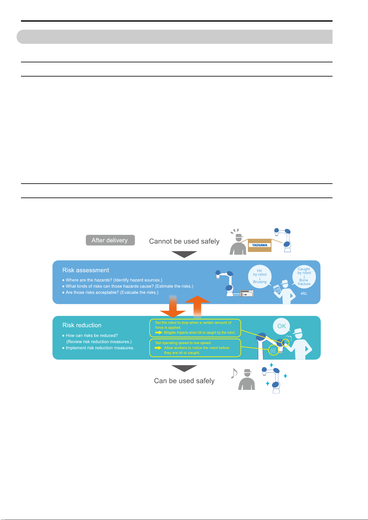
A collaborative robot cannot be used safely as-is and without a safety fence when delivered. The customer
(including the system integrator) must conduct risk assessments and implement risk reduction measures on their
own, and then check if potential hazards have been eliminated.
8
Page 9
i.1.3 Applicable Products
HW2480573
9/144
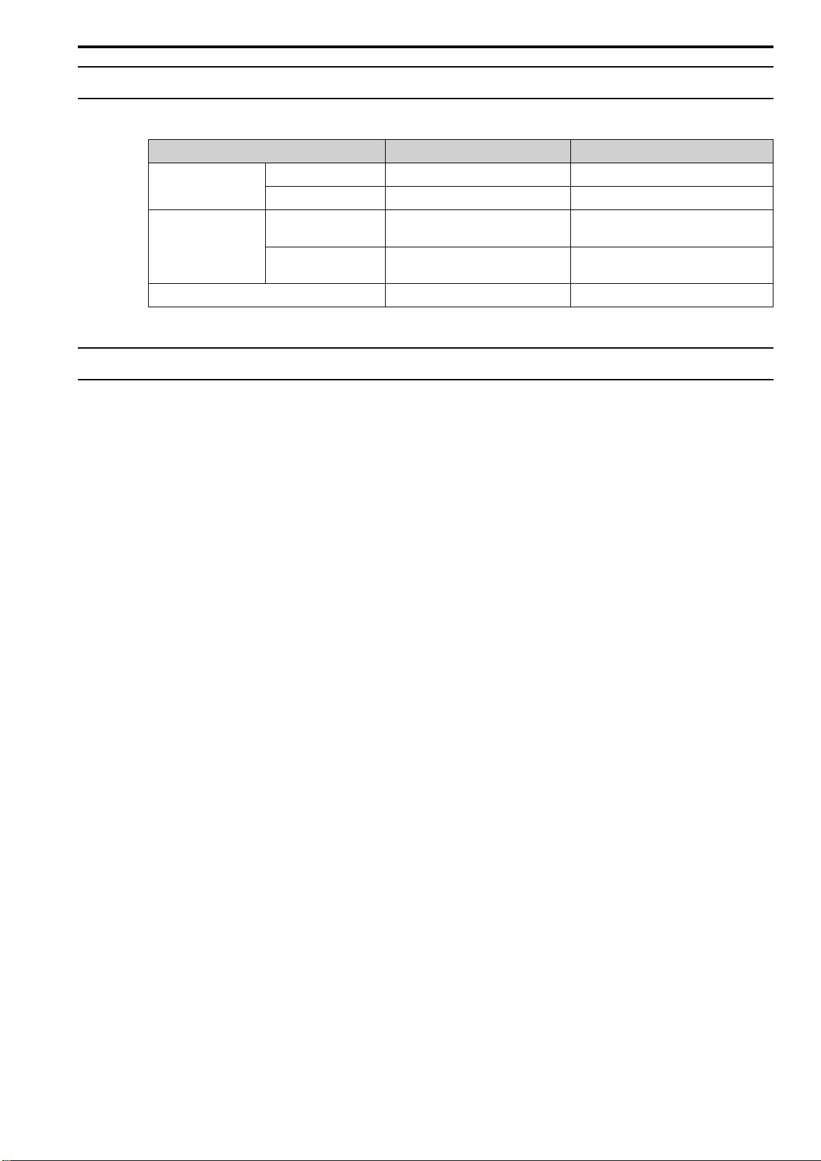
This manual describes the following products.
Product Type Specifications
Robot controller YRC1000 ERAR-1000-06VX8-*** −
YRC1000micro ERBR-100-06VX8-*** −
i.1 Introduction to This Manual
Manipulator Dust-proof/drip-proof
specification
Food specification YR-1-06VXCP10-F00 Built-in air hoses, Ethernet and I/O cables
Smart Pendant JZRCR-APP30-1 −
i.1.4 Related Manuals
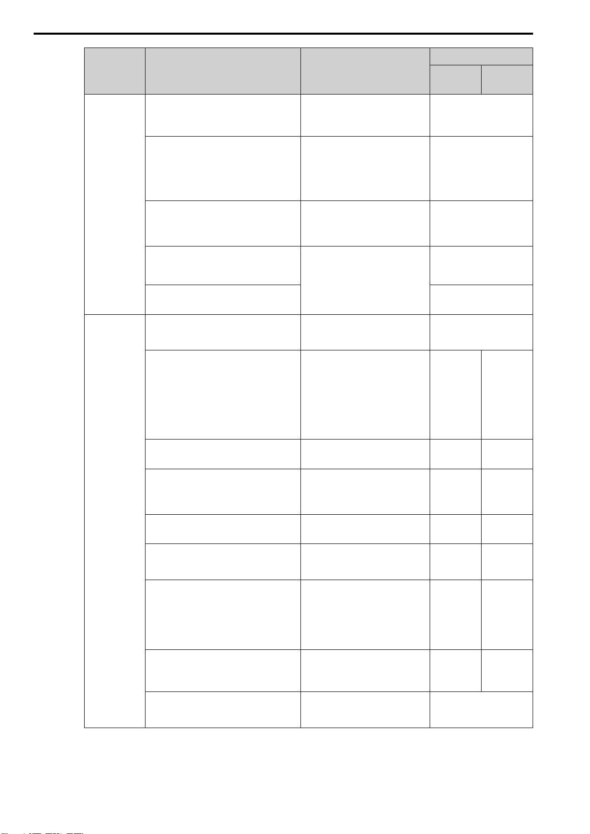
The following manuals describe the precautions, control functions, usage procedures, and troubleshooting procedures when using a robot in detail.
Refer to these manuals for detailed procedures on using the product.
YR-1-06VXCP10-B00 Built-in air hoses, Ethernet and I/O cables
specification
specification
9
Page 10
i.1 Introduction to This Manual
HW2480573
10/144
Category Manual Name Overview
Manipulator MOTOMAN-HC10DTP
Instructions
Dust-Proof/Drip-Proof Specification
MOTOMAN-HC10DTFP
Supplemental Instructions
MOTOMAN-HC10DTP Dust-Proof/DripProof Specification/MOTOMAN-HC10DTFP
Maintenance Manual
MOTOMAN-HC10DTP Dust-Proof/DripProof Specification
Setup Guide
MOTOMAN-HC10DTFP
Setup Guide
Robot Controller YRC1000/YRC1000micro
Collaborative Operation Instructions
Describes information about the
manipulator, such as basic specifications, installation, and spare parts.
Describes the differences from the
MOTOMAN-HC10DTP dust-proof/
drip-proof specification in the various
aspects of the manipulator, such as
internal wiring, chemical resistance,
and spare parts.
Describes the maintenance procedures
for the manipulator, such as precautions for inspections and procedures
for replacing parts.
Describes the setup procedures and
manuals for users to refer to when
installing the manipulator for the first
time after the product has been
delivered.
Describes information on collaborative
operation functions and configuration
procedures.
Manual No.
YRC1000
HW2480392
HW2480461
HW2480454
HW2380357
HW2380359
HW1484764
*1
YRC1000
micro
YRC1000/YRC1000micro
Supplementary Instructions for HC Series
YRC1000/YRC1000micro
Notes for Safe Operation
YRC1000/YRC1000micro
Maintenance Manual
YRC1000/YRC1000micro
Options Instructions for Inform Language
YRC1000/YRC1000micro
Options Instructions for Concurrent I/O
YRC1000/YRC1000micro
Instructions
YRC1000/YRC1000micro
Alarm Codes
(Major Alarms) (Minor Alarms)
Describes the differences between
standard robots and collaborative
robots in the following main robot controller manuals.
• Instructions
• Maintenance Manual
• Instructions for Functional Safety
Function
Describes the residual risks and safety
precautions when using a robot.
Describes the maintenance procedures
for the robot controller, such as periodic inspections and procedures for
replacing parts.
Describes the instructions used by the
robot controller.
Describes concurrent I/O, which is an
I/O control function in the robot
controller.
Describes the following items in
details:
• Robot safety precautions
• Robot controller specifications,
installation, and wiring
• Robot control functions
Describes the causes of and corrective
actions for alarms.
HW1484756 HW1485285
R-AN-A308 R-AN-A309
RE-CHO-
A114
RE-CKI-A466 RE-CKI-A468
RE-CKI-A467 RE-CKI-A469
RE-CTO-
A221
RE-CER-
A600
RE-CHO-
A115
RE-CTO-
A222
RE-CER-
A601
*1 Read the manual for the robot controller that will be used.
10
YRC1000/YRC1000micro
Instructions for Smart Pendant
Describes detailed information on
Smart Pendant functions and operating
procedures.
HW1485509
Page 11
i.2 Notes for Safe Operation
HW2480573
11/144
i.2.1 Safety Information
To prevent personal injury and equipment damage in advance, the following signal words are used to indicate
safety precautions in this manual. The signal words are used to classify the hazards and the degree of damage or
injury that may occur if a product is used incorrectly. Information marked as shown below is important for safety.
Always read this information and heed the precautions that are provided.
DANGER
Indicates precautions that, if not heeded, are likely to result in loss of life, serious injury, or
fire.
WARNING
Indicates precautions that, if not heeded, could result in loss of life, serious injury, or fire.
i.2 Notes for Safe Operation
Indicates precautions that, if not heeded, could result in relatively serious or minor injury, or
in fire.
Indicates precautions that, if not heeded, could result in property damage.
i.2.2 Visual Aids
The following aids are used to indicate certain types of information for easier reference.
Indicates precautions or restrictions that must be observed. Also indicates alarm displays and other precautions that will not
result in machine damage.
Important
Indicates definitions of difficult terms or terms that have not been previously explained in this manual.
Term
Information
Indicates supplemental information to deepen understanding or useful information.
CAUTION
NOTICE
11
Page 12

i.2 Notes for Safe Operation
HW2480573
12/144
i.2.3 General Precautions
• Figures provided in this manual are typical examples or conceptual representations. There may be differences between them and actual
wiring, circuits, and products.
• The products shown in illustrations in this manual are sometimes shown with their covers or protective guards removed to illustrate
detail. Always replace all covers and protective guards before the product is used.
• If a new copy of this manual is required because it has been lost or damaged, contact your nearest YASKAWA representative or one of
the offices, and inform them of the manual number.
• This manual is subject to change without notice for product improvements, specifications changes, and improvements to the manual
itself. The manual number of this manual will be updated and revisions issued when changes are made.
• Any and all quality guarantees provided by YASKAWA are null and void if the customer modifies the product in any way. YASKAWA
disavows any responsibility for damages or losses that are caused by modified products.
12
Page 13
i.3 Using This Manual
HW2480573
13/144
i.3.1 Terms
"MOTOMAN" is the product name for industrial robots manufactured by YASKAWA.
MOTOMAN consists of a manipulator, which is the robot itself, a robot control panel, a Smart Pendant, and a
manipulator cable.
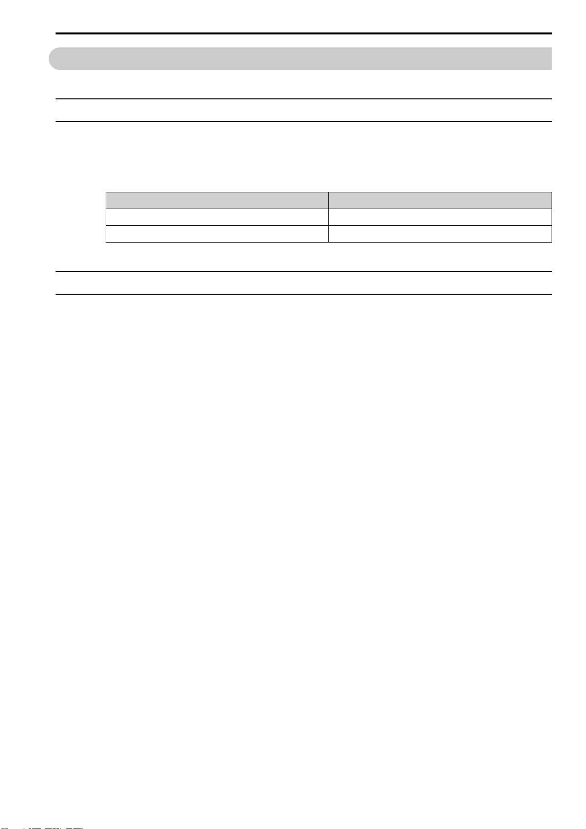
Interpret the devices described in this manual as shown below.
Device Name in This Manual
Robot Manipulator
Robot control panel Robot controller
i.3.2 Trademarks
The product names and company names used in this manual are the trademarks or registered trademarks of the
respective company. TM and the ® mark do not appear with product or company names in this manual.
i.3 Using This Manual
13
Page 14

i.3 Using This Manual
HW2480573
14/144
14
Page 15

1
HW2480573
15/144
Unpacking and Checking the Product
1.1 Unpacking the Shipping Crate .............................................................................. 16
1.2 Checking the Received Products ......................................................................... 17
1.2.1 Components in a Basic Robot System ......................................................... 17
1.2.2 Manipulator Accessories................................................................................ 18
1.2.3 YRC1000 Robot Controller Accessories....................................................... 18
1.2.4 YRC1000micro Robot Controller Accessories............................................. 19
1.2.5 Verifying the Order Numbers ......................................................................... 19
15
Page 16

1.1 Unpacking the Shipping Crate
HW2480573
16/144
1.1 Unpacking the Shipping Crate
NOTICE
When the manipulator and controller are received in a shipping crate, unpack them in a level
location near the installation location of the manipulator.
If the products are unpacked in an unstable location, there is a risk the manipulator and robot controller may
fall over and be damaged.
The Smart Pendant may also be dropped and damaged.
16
Page 17
1.2 Checking the Received Products
HW2480573
17/144
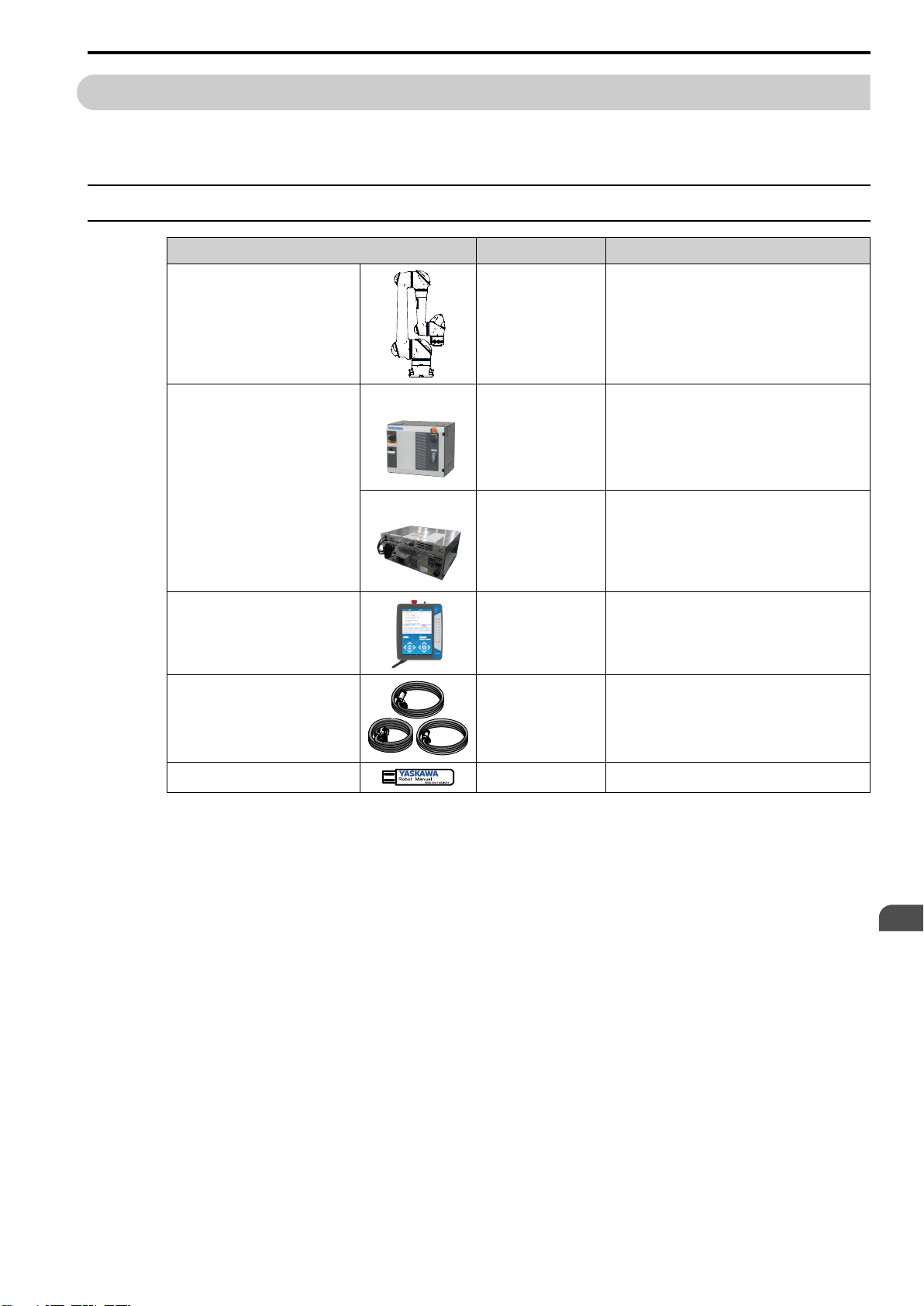
Confirm that all of the ordered products have been received.
1.2.1 Components in a Basic Robot System
Name Standard/Option Remarks
Manipulator Standard component Includes accessories.
1.2 Checking the Received Products
Robot controller
YRC1000
or YRC1000micro
Smart Pendant
Manipulator cables (3 types) Standard component Connects the manipulator and robot controller.
CD-ROM (connected to a USB port) Standard component Contains PDF copies of the manuals.
YRC1000
YRC1000micro Standard component Includes spare parts.
Standard component Includes spare parts.
Standard component Mode selector key (2 keys)
• Manipulator cable
• Torque sensor cable (TQ)
• Switch/lamp cable (SW)
Unpacking and Checking the Product
1
17
Page 18
1.2 Checking the Received Products
HW2480573
18/144
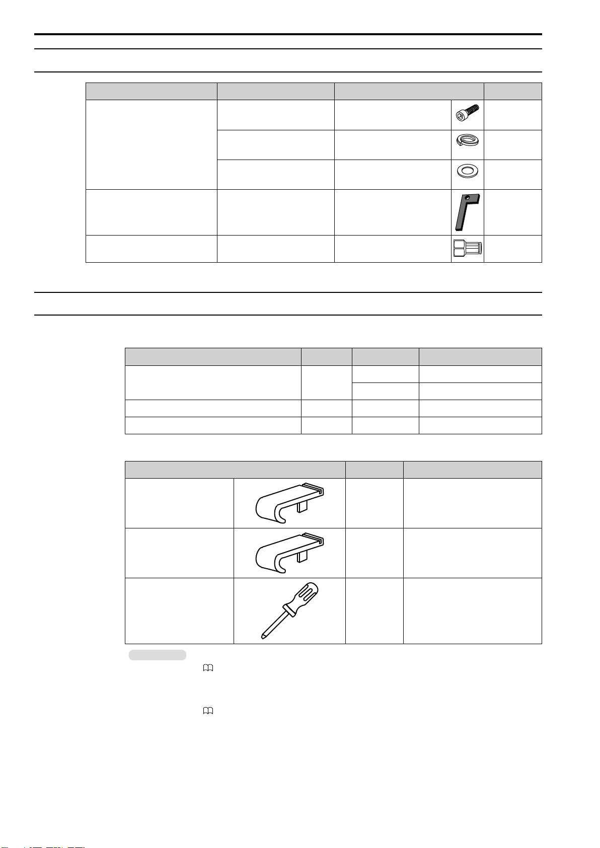
1.2.2 Manipulator Accessories
Purpose Name Type/Specifications Quantity
Installing the manipulator Hexagon socket head cap screw
*trivalent chromate*
Spring washer
*stainless steel*
Washer
*stainless steel*
Home positioning of the manipulator's
axes (HC10DTFP only)
Grease replenishment for the
manipulator
Jig HW1410428-1 1
Union KQ2F06-01N 6
M12 (length: 45 mm) 4
M12 4
M12 4
1.2.3 YRC1000 Robot Controller Accessories
1. Replacement Fuses
Name Quantity Specifications Type
10-A fuse 2 10 A, 500 VAC FNQ-10 10A, 500VAC
10 A, 600 VAC SC-10 10A, 600VAC
Glass cartridge fuse 1 3.15 A, 250 V 02173.15P 3.15A, 250V
Micro fuse 1 1.0 A, 250 V HM10 1.0A, 250V
2. Tools for Wiring
Name Quantity Type
Wiring tool for WAGO
connectors
Wiring tool for WAGO
connectors
Wiring tool for WAGO terminal
block
Information
1. The fuses are replacement parts. Refer to the following manual for details on replacement procedures.
YRC1000 Maintenance Manual (Manual No.: RE-CHO-A114)
2. Use the wiring tool for WAGO connectors when connecting wires to the control power supply unit and
general-purpose I/O circuit board in the robot controller. Refer to the following manual for details on
wiring procedures.
YRC1000 Instructions (Manual No.: RE-CTO-A221)
2 231-131
1 734-230
1 210-119SB
18
Page 19
1.2 Checking the Received Products
HW2480573
19/144
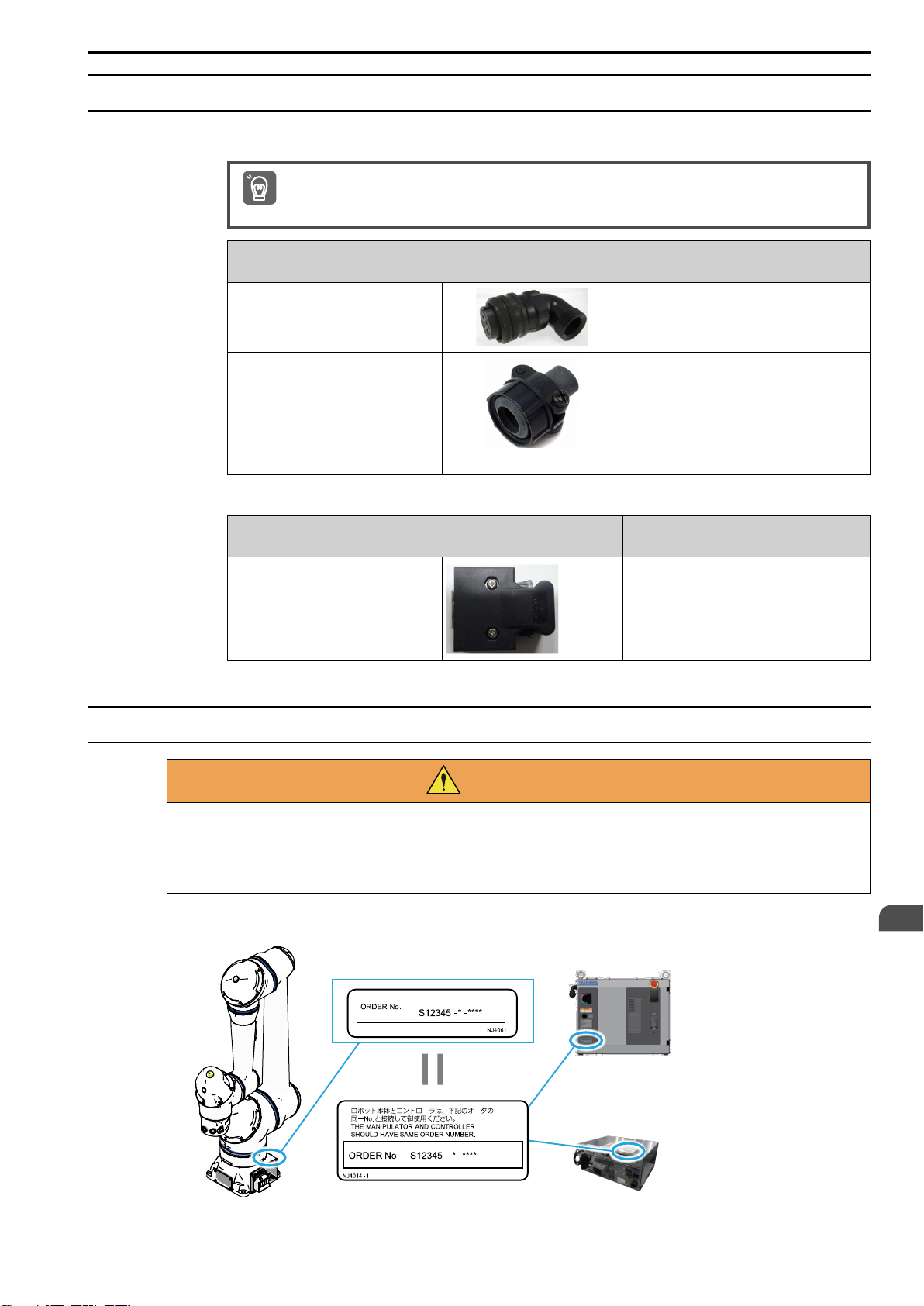
1.2.4 YRC1000micro Robot Controller Accessories
1. Parts for Connecting the Primary Power Supply
Cable clamps, power outlet plugs, and power wires (cables) are not included with the product. The customer is
responsible for these parts.
Important
Name
L-shaped angled plug for the primary
power supply cable
End bell
2. Part for Short-Circuiting the Safety Signals
Name
Dummy connector (Safety) for short-circuiting the safety signals
Quan-
tity
1 CE05-8A18-10SD-D-BAS(R1)
1 CE3057-10A-1-D
Quan-
tity
1 CBL-AR001
Type
Type
1.2.5 Verifying the Order Numbers
Verify the order numbers on the robot and robot controller are the same. Each robot was
configured with unique home position data at the factory. Use extra caution when installing
multiple robots.
There is a risk of injury or damage due to malfunction.
Verify that the order numbers on the nameplates of the manipulator and robot controller
match.
WARNING
Unpacking and Checking the Product
1
19
Page 20

1.2 Checking the Received Products
HW2480573
20/144
20
Page 21

2
HW2480573
21/144
Transportation and Installation
2.1 Transporting the Manipulator................................................................................ 22
2.2 Installing the Manipulator ...................................................................................... 25
2.2.1 Required Items................................................................................................. 25
2.2.2 Strength of the Installation Surface .............................................................. 25
2.2.3 Fixing the Manipulator to the Floor ............................................................... 26
2.2.4 Grounding the Manipulator ............................................................................ 27
2.3 Transporting the YRC1000 Robot Controller .................................................... 28
2.4 Installing the YRC1000 Robot Controller ........................................................... 29
2.5 Transporting the YRC1000micro Robot Controller ......................................... 31
2.6 Installing the YRC1000micro Robot Controller ................................................ 32
21
Page 22
2.1 Transporting the Manipulator
HW2480573
22/144
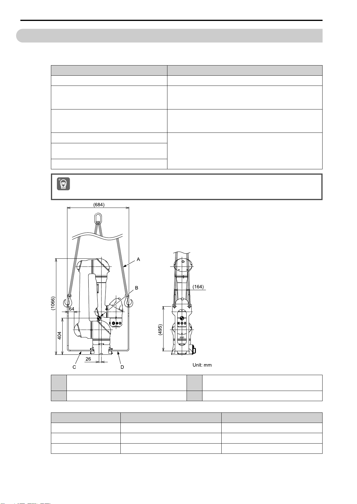
2.1 Transporting the Manipulator
Mass: 70 kg (including the shipping brackets)
Table 2.1 Required Items
Name Remarks
Hex key For removing the shipping brackets.
Torque wrench For mounting the shipping brackets.
However, this is not necessary because the shipping brackets are mounted to
the manipulator when shipped from the factory.
Hanging tool Example: Wire or nylon sling.
Be sure to use a hanging tool for a four-wire sling with a length of 2000 mm or
longer.
Shipping bracket (2 brackets) Included with the manipulator. The manipulator is shipped from the factory
Hexagon socket head cap screw M6 (length: 25 mm) (4
screws)
Conical spring washer M6 (4 washers)
When moving the manipulator to another location, such as when changing the production line, set the manipulator to the
following transportation posture.
Important
with these parts mounted as the transportation parts.
Hanging tool (for four-wire sling with a length of 2000 mm
A
or longer)
B Position of the center of gravity: 70 kg D Shipping bracket 2 (type: HW1308926-1)
22
C Shipping bracket 1 (type: HW1308925-1)
Table 2.2 Angle and Pulses of Each Axis When Shipped from the Factory
Axis Pulses Angle
S 0 0°
L 0 0°
U -211268 -90°
Continued on next page.
Page 23
2.1 Transporting the Manipulator
HW2480573
23/144
Continued from previous page.
Axis Pulses Angle
R 0 0°
B 0 0°
T 0 0°
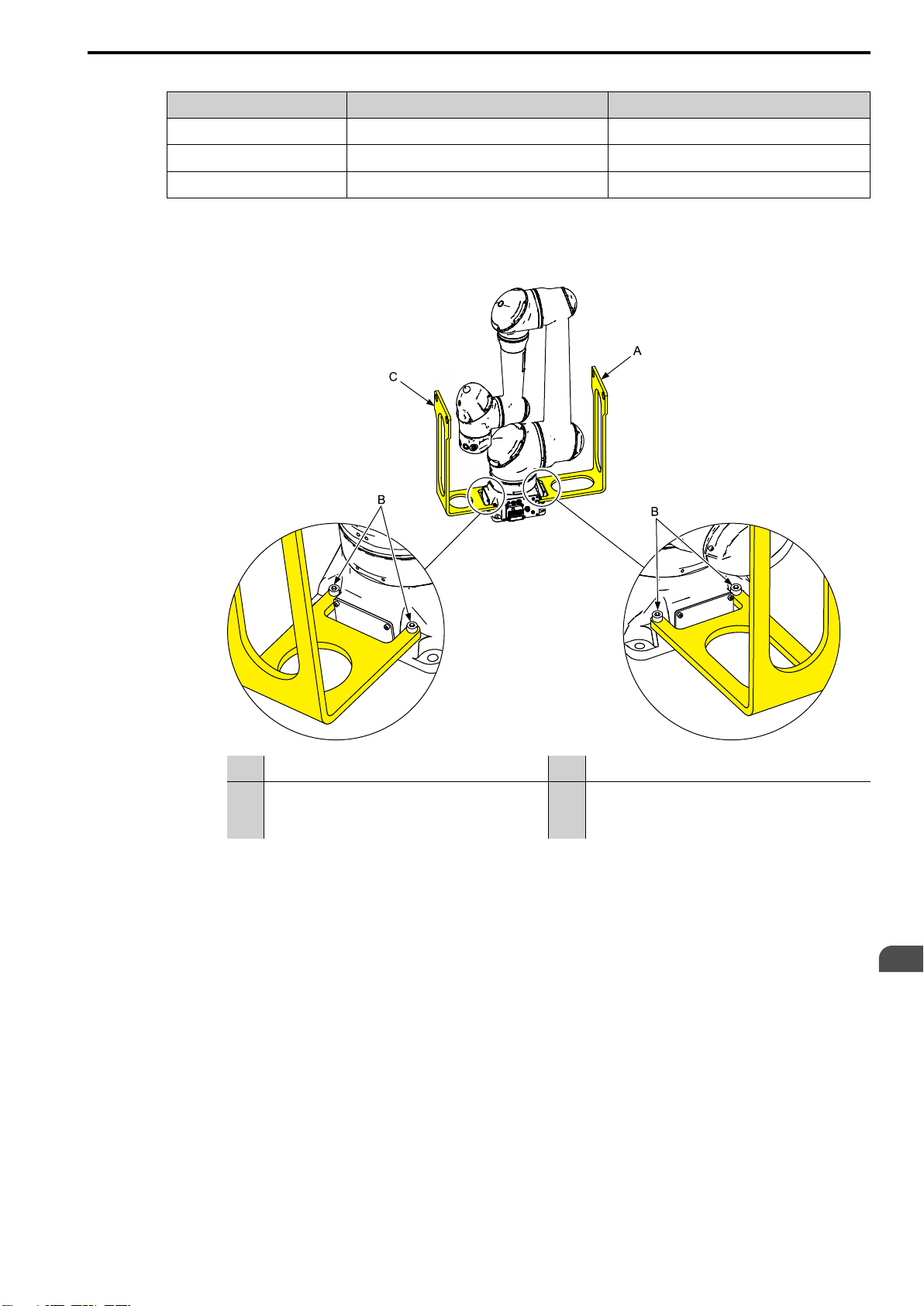
1. The transportation parts (shipping brackets, hexagon socket head cap screws, and con-
ical spring washers) are mounted to the manipulator when it is shipped from the factory.
Check again that the hexagon socket head cap screws have been fastened before transporting the manipulator. Tightening torque: 9.8 N∙m (1.0 kgf∙m)
A Shipping bracket 1 (type: HW1308925-1) C Shipping bracket 2 (type: HW1308926-1)
• Hexagon socket head cap screw M6 (length: 25 mm)
(4 screws)
B
• Conical spring washer M6 (4 washers)
- -
Transportation and Installation
2
23
Page 24
2.1 Transporting the Manipulator
HW2480573
24/144
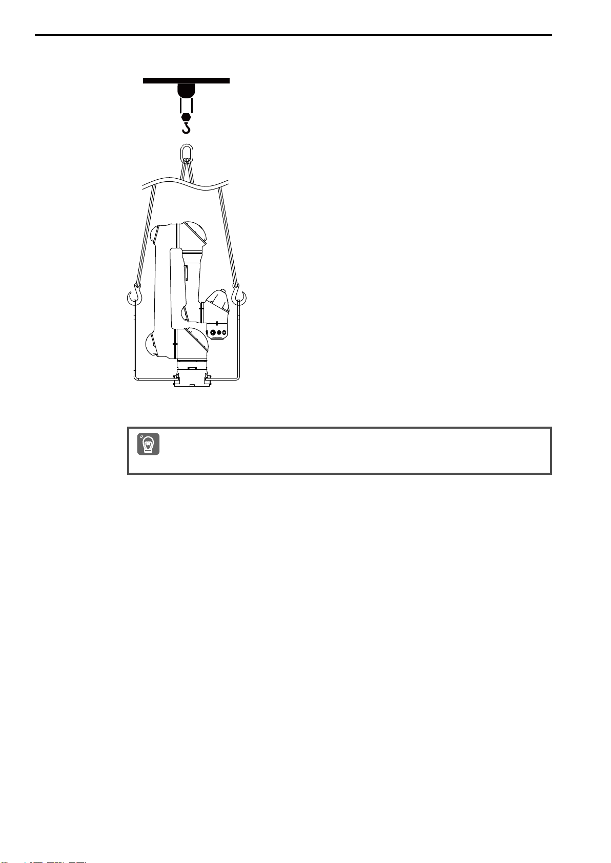
2. Pass the hooks of the hanging tool through each hole in two places on the two shipping
brackets, hoist the manipulator with a crane, and transport it to the installation location.
3. Remove the shipping brackets.
Carefully store the transportation parts (shipping brackets, hexagon socket head cap screws, and conical spring
washers) that were removed. The transportation parts are required when moving and transporting the manipulator again.
Important
24
Page 25
2.2 Installing the Manipulator
HW2480573
25/144
WARNING
Do not use the manipulator when it is not fixed to the installation surface with bolts.
The manipulator may fall over and cause injury or damage.
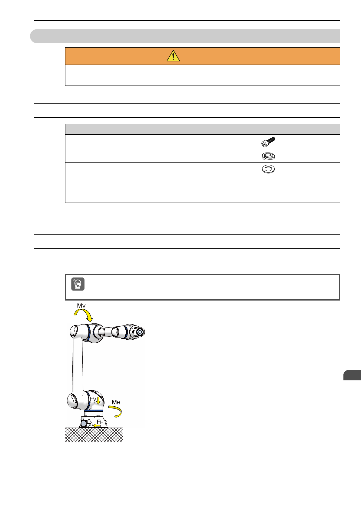
2.2.1 Required Items
Name Type/Specifications Quantity
2.2 Installing the Manipulator
Hexagon socket head cap screw *trivalent chromate*
Spring washer *stainless steel*
Washer *stainless steel*
Baseplate
Anchor bolt
*1 Included with the manipulator.
*2 Not provided by YASKAWA.
*2
*2
*1
*1
*1
M12 (length: 45 mm) 4
2.2.2 Strength of the Installation Surface
The installation of the manipulator is critical for maintaining appropriate functionality. Design and construct a
base that can fully withstand the maximum reaction force of the manipulator.
Ensure the installation surface of the manipulator has a flatness of 0.5 mm or lower. If the flatness of the installation surface
is poor, the manipulator may deform and lose appropriate functionality.
Important
M12 4
M12 4
A thickness of 32 mm or greater is
recommended.
M12 or larger is recommended. 4
1
Transportation and Installation
2
25
Page 26

2.2 Installing the Manipulator
HW2480573
26/144
Table 2.3 Manipulator Installation Reaction Force/Torque
When Rotating Horizontally When Rotating Vertically
Reaction Force F
During an emergency stop 2600 N
(265 kgf)
During acceleration/
deceleration
834 N
(85 kgf)
H
Torque M
1842 N∙m
(188 kgf∙m)
559 N∙m
(57 kgf∙m)
2.2.3 Fixing the Manipulator to the Floor
1. Fix the baseplate to the floor with the anchor bolts.
2. Fix the manipulator to the baseplate with the hexagon socket head cap screws. (4
screws) Tightening torque: 84 N∙m (8.6 kgf∙m)
H
Reaction Force F
932 N
(95 kgf)
343 N
(35 kgf)
V
Torque M
1842 N∙m
(188 kgf∙m)
696 N∙m
(71 kgf∙m)
V
Hexagon socket head cap screw M12 *trivalent chromate* (length: 45
A
mm) (4 screws)
B Spring washer M12 *stainless steel* (4 washers) E
C Washer M12 *stainless steel* (4 washers) F Anchor bolt (M12 or larger is recommended)
D Manipulator base
Baseplate (with a thickness of 32 mm or greater is
recommended)
26
Page 27
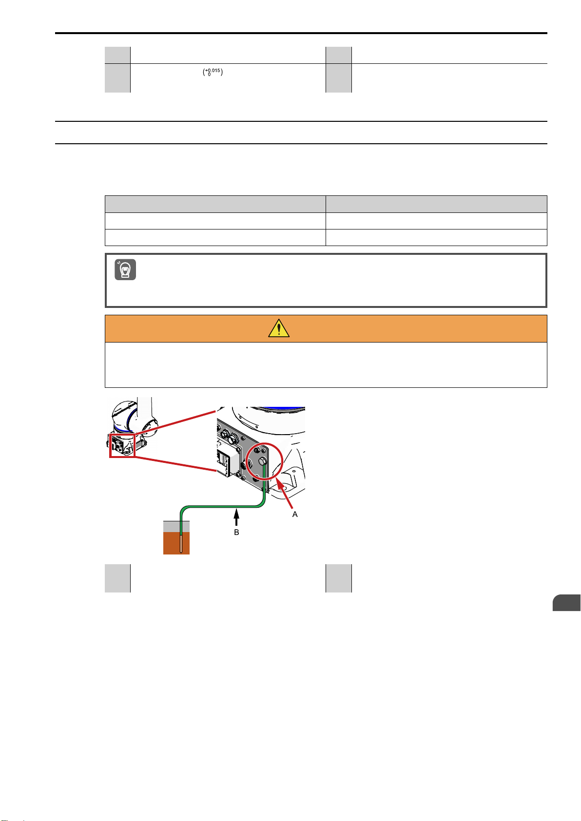
A Baseplate C Hole for mounting body: φ14 (4 places)
HW2480573
27/144
Reference hole: φ8H7
B
Reamed hole depth: 10
2.2.4 Grounding the Manipulator
Ground the manipulator to a ground resistance of 100 Ω or less in accordance with all relevant local and national
electrical codes. Connect the manipulator directly to the ground wire.
Table 2.4 Required Items
Name Remarks
2
5.5 mm
or larger ground wire This part is not provided by YASKAWA.
Spanner/wrench For tightening the grounding bolt.
• Do not share the ground wire for the manipulator with any other ground wires or grounding electrodes, such as those for
electrical power, motors, or welders.
Important
• Ground the manipulator in accordance with all relevant local and national electrical codes when using metallic ducts, met-
allic conduits, or cable trays to install cables.
2.2 Installing the Manipulator
– –
WARNING
Always connect the ground terminal to a grounding electrode with a resistance of 100 Ω or
less.
There is a risk of fire or electric shock.
Bolt M8 (for grounding)
A
Included on the manipulator.
B Ground wire (5.5 mm
2
or larger)
Transportation and Installation
2
27
Page 28
2.3 Transporting the YRC1000 Robot Controller
HW2480573
28/144
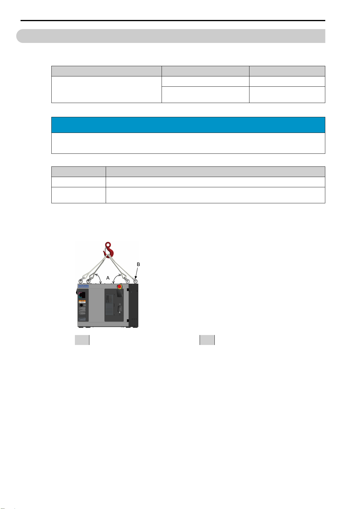
2.3 Transporting the YRC1000 Robot Controller
The mass of the YRC1000 robot controller depends on the model as given below.
Table 2.5 YRC1000 Robot Controller Mass
YRC1000 Robot Controller Model Specifications Approx. Mass (kg)
Small-capacity model Specification for Japan 60
Specification for Asia, North America, and
Europe
As a basic rule, use a crane when transporting the YRC1000 robot controller.
70
NOTICE
Transport the product so that it is not exposed to excessive vibration or shock.
Performance will be affected because this product is a precision machine.
Table 2.6 Required Items
Name Remarks
Eye bolt Included with the robot controller when shipped from the factory.
Hanging tool This part is not provided by YASKAWA. Select a wire or nylon sling according to the mass of the robot
1. The eye bolts are attached to the robot controller when shipped from the factory. Check
again that the eye bolts have been fastened before transporting the manipulator.
2. Pass the hanging tool through the eye bolts, hoist the robot controller with a crane, and
transport it to the installation location.
controller.
28
A 45° or wider B Eye bolt M12 (4 bolts)
Page 29
2.4 Installing the YRC1000 Robot Controller
HW2480573
29/144
2.4 Installing the YRC1000 Robot Controller
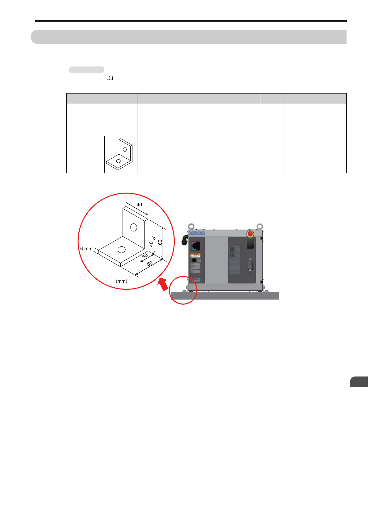
A bracket for fixing the robot controller is not provided by YASKAWA. The recommended bracket is given
below.
Information
Refer to the following manual for details on the installation environment of the robot controller.
YRC1000 Instructions (Manual No.: RE-CTO-A221)
Table 2.7 Required Items (Recommended Items)
Name Recommended Specifications Quantity Remarks
Mounting screw M12 (length: 20 mm)
Note:
Select the screws based on a thread length of 14 mm for the
sides of the robot controller.
Fixing bracket Hole φ14 (2 places)
Plate thickness 6 mm
Tightening torque: 45 N∙m
(4.6 kgf∙m)
4
–
4
Use the screw holes (M12) on the sides of the robot controller to fix it to the floor or a
pedestal.
Transportation and Installation
2
29
Page 30
2.4 Installing the YRC1000 Robot Controller
HW2480573
30/144
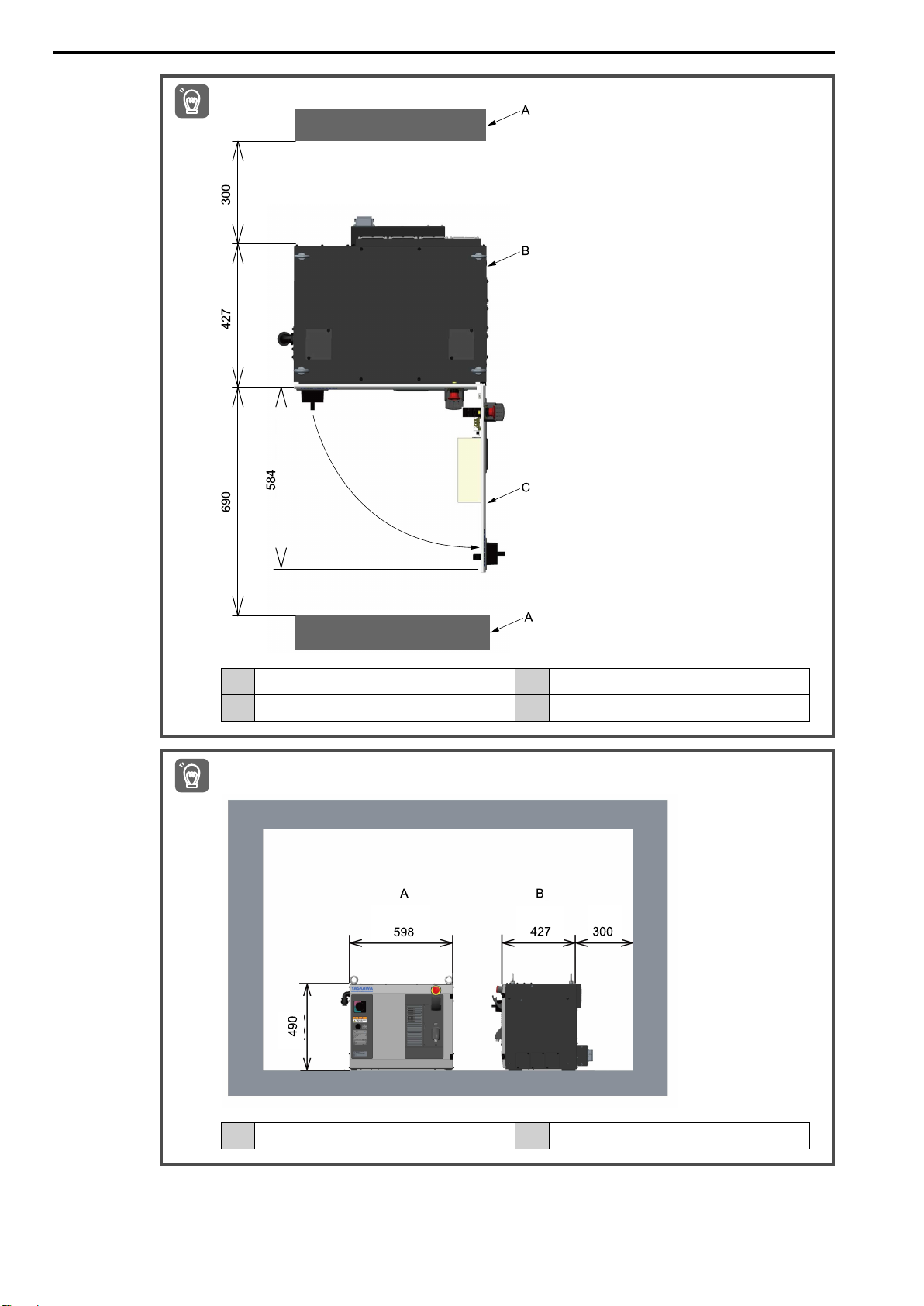
Ensure space to open the robot controller door for inspection.
Important
Important
A Wall C Robot controller door
B Robot controller – –
For the work space during maintenance, install the YRC1000 robot controller in a location with a gap of approximately 300 mm or greater from the walls.
30
A Front side of robot controller B Side of robot controller
Page 31

2.5 Transporting the YRC1000micro Robot Controller
HW2480573
31/144
2.5 Transporting the YRC1000micro Robot Controller
The mass of the YRC1000micro robot controller depends on the specifications as given below.
Table 2.8 YRC1000micro Robot Controller Mass
YRC1000micro Robot Controller Specifications Approx. Mass (kg)
Specification for Japan, North America, and Asia 16.5
Specification for Europe 20
When transporting the YRC1000micro robot controller, use a cart or have two workers lift and carry the robot
controller from its bottom. Be careful not expose the product to excessive vibration or shock during transport.
Note:
Use a lifter to lower the product from a rack or shelf.
Transportation and Installation
2
31
Page 32
2.6 Installing the YRC1000micro Robot Controller
HW2480573
32/144
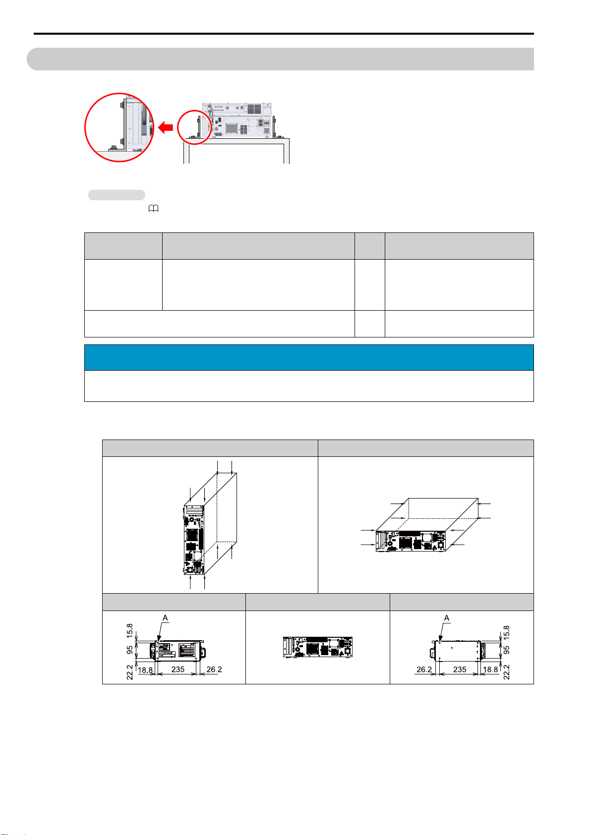
2.6 Installing the YRC1000micro Robot Controller
A bracket for fixing the robot controller is not provided by YASKAWA.
Figure 2.1 Installation Example of the YRC1000micro Robot Controller
Information
Refer to the following manual for details on the installation environment of the robot controller.
YRC1000micro Instructions (Manual No.: RE-CTO-A222)
Table 2.9 Required Items
Name Specifications
Mounting screw M5
Note:
Select screws with a thread length that is the thickness of
the fixing bracket + 5 mm or less.
Fixing bracket 4 Prepare fixing brackets according to the
Quan-
tity
12 Material: Mild steel or a stronger material
mounting method of the robot controller.
Remarks
NOTICE
If the thread length of the mounting screws exceeds the thickness of the mounting bracket +
5 mm, the components inside the robot controller may be damaged.
Use the screw holes M5 (8 places) on the sides of the robot controller to fix it to the floor or
a pedestal.
Side Mounted Horizontally Mounted
A M5 tapped holes (hole depth: 5 mm) (4 places)
32
Left Side View Front Side View Right Side View
Page 33
2.6 Installing the YRC1000micro Robot Controller
HW2480573
33/144
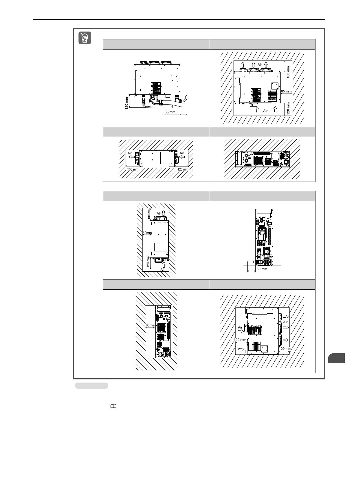
1. Ensure the following space when the YRC1000micro robot controller lays flat (horizontally mounted).
Important
Space for Manipulator Cable Top Side View
Left Side View Front Side View
2. Ensure the following space when the YRC1000micro robot controller is side mounted.
Top Side View Space for Manipulator Cable
Information
Front Side View Right Side View
Transportation and Installation
2
The YRC1000micro robot controller is free-standing. Install the robot controller so that it is not exposed to excessive shock.
Refer to the mounting procedures in the following manual when side mounting the robot controller.
YRC1000micro Instructions (Manual No.: RE-CTO-A222)
33
Page 34

2.6 Installing the YRC1000micro Robot Controller
HW2480573
34/144
34
Page 35

3
HW2480573
35/144
Connecting the Robot Controller
3.1 Connecting the YRC1000 Robot Controller and Other Devices ................... 36
3.1.1 Connecting the Manipulator........................................................................... 36
3.1.2 Connecting the Primary Power Supply......................................................... 39
3.1.3 Connecting the Smart Pendant...................................................................... 42
3.2 Connecting the YRC1000micro Robot Controller and Other
Devices........................................................................................................................ 43
3.2.1 Connecting the Manipulator........................................................................... 43
3.2.2 Connecting the Primary Power Supply......................................................... 46
3.2.3 Connecting the Smart Pendant...................................................................... 47
35
Page 36
3.1 Connecting the YRC1000 Robot Controller and Other Devices
HW2480573
36/144
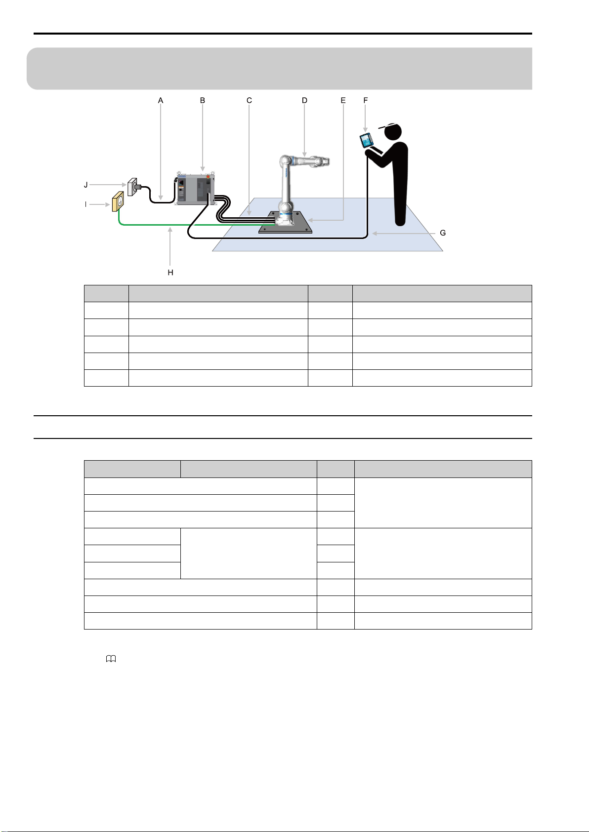
3.1 Connecting the YRC1000 Robot Controller and Other
Devices
Symbol Name Symbol Name
A Primary power supply cable F Smart Pendant
B Robot controller G Pendant connection cable
C Manipulator cables (3 types) H Ground wire
D Manipulator I Grounding equipment (earth)
E Baseplate J Primary power supply
3.1.1 Connecting the Manipulator
Table 3.1 Required Items
Name Specifications Quantity Remarks
Manipulator cable 1 Included with the manipulator.
Torque sensor cable 1
Switch/lamp cable 1
Power supply cable
Power outlet plug
Ground wire
Earth leakage breaker
Phillips screwdriver 1 –
*1
*1
*1
Power requirement 1.0 kVA
Cable size 3.5 mm
*2
2
3 Robot controller breaker capacity: 15 A
1
1
1 –
Flat head screwdriver 1 –
*1 Not provided by YASKAWA.
*2 Refer to the following manual for selecting the earth leakage breaker.
36
YRC1000 Instructions (Manual No.: RE-CTO-A221)
Page 37
3.1 Connecting the YRC1000 Robot Controller and Other Devices
HW2480573
37/144
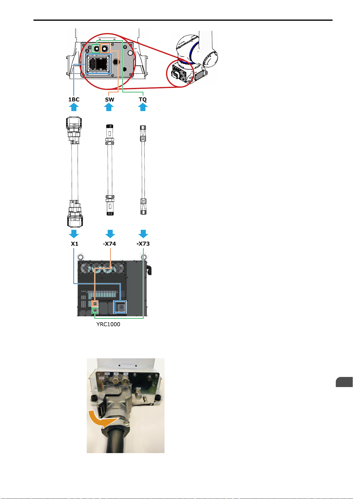
1. Connect the 1BC connector on the manipulator cable to the manipulator.
Insert the manipulator cable into the 1BC connector, and turn the connector lever on the manipulator
cable side to the locked position to connect the connector.
Connecting the Robot Controller
3
37
Page 38
3.1 Connecting the YRC1000 Robot Controller and Other Devices
HW2480573
38/144
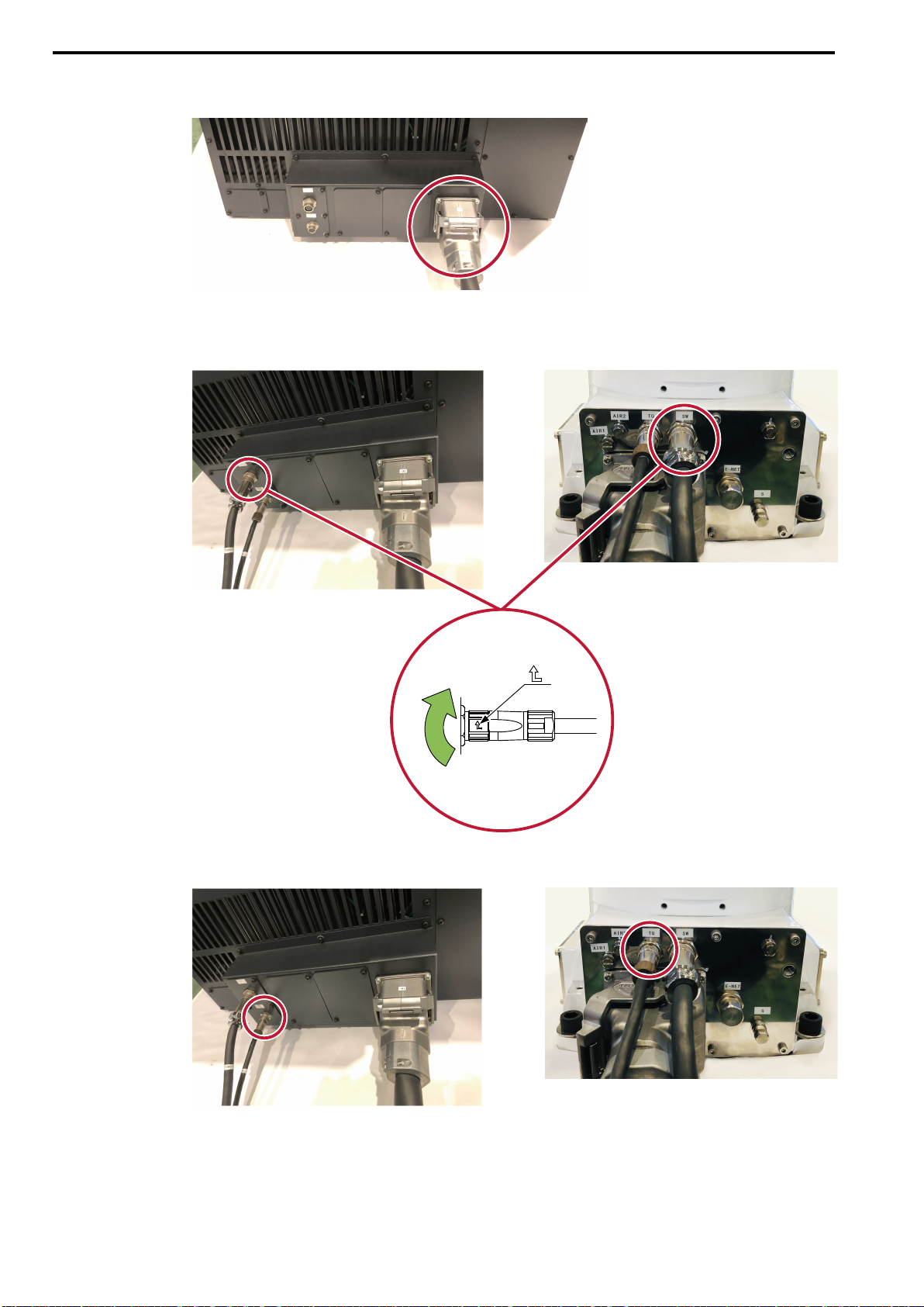
2. Use the same procedure to connect the X1 connector on the manipulator cable to the
robot controller.
3. Connect the switch/lamp cable to the [SW] connector on the manipulator and the [-X74]
connector on the robot controller.
Turn the tip of the cable connector with the arrow in the direction of the arrow to lock the cable.
4. Use the same procedure to connect the torque sensor cable to the [TQ] connector on
38
the manipulator and the [-X73] connector on the robot controller.
Page 39
3.1 Connecting the YRC1000 Robot Controller and Other Devices
HW2480573
39/144
3.1.2 Connecting the Primary Power Supply
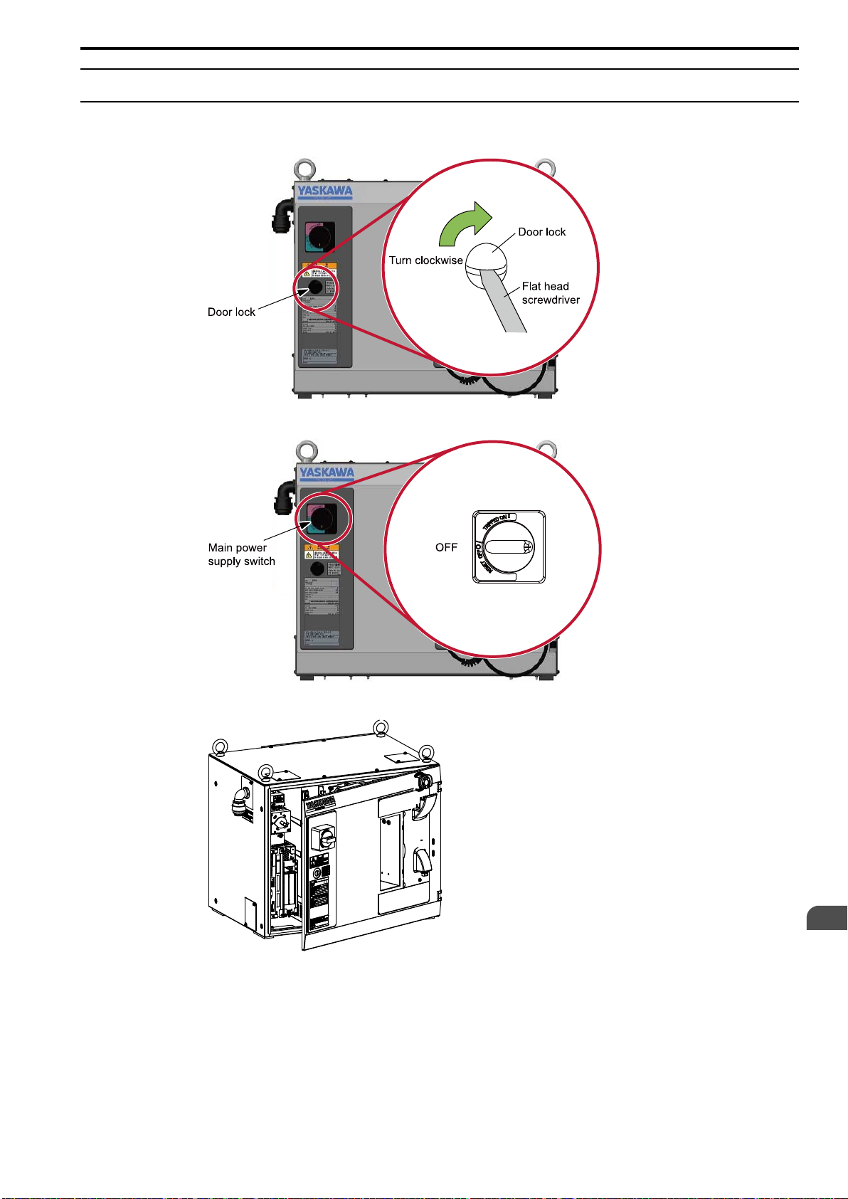
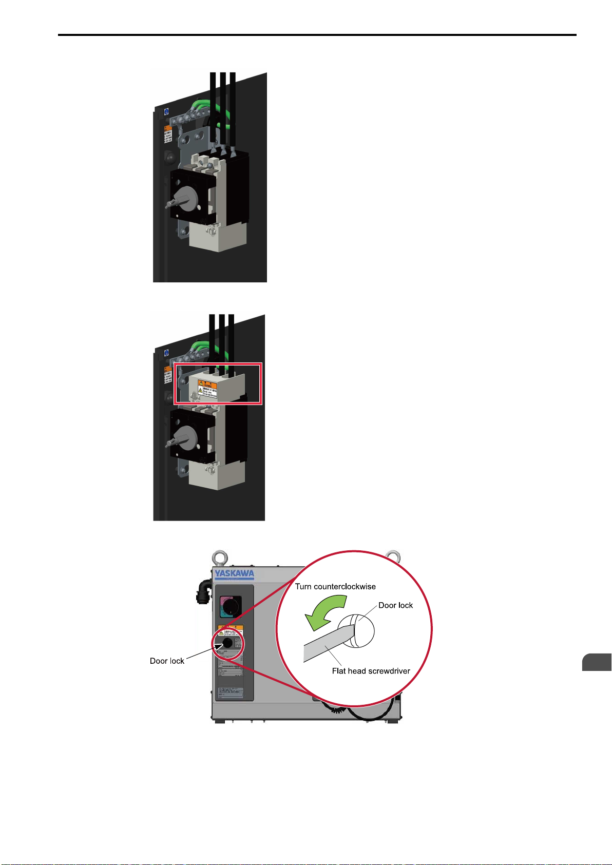
1. Using a flat head screwdriver, rotate the door lock of the robot controller 90 degrees
clockwise.
2. Turn the main power supply switch to the OFF position.
3. Open the robot controller door.
Connecting the Robot Controller
3
39
Page 40
3.1 Connecting the YRC1000 Robot Controller and Other Devices
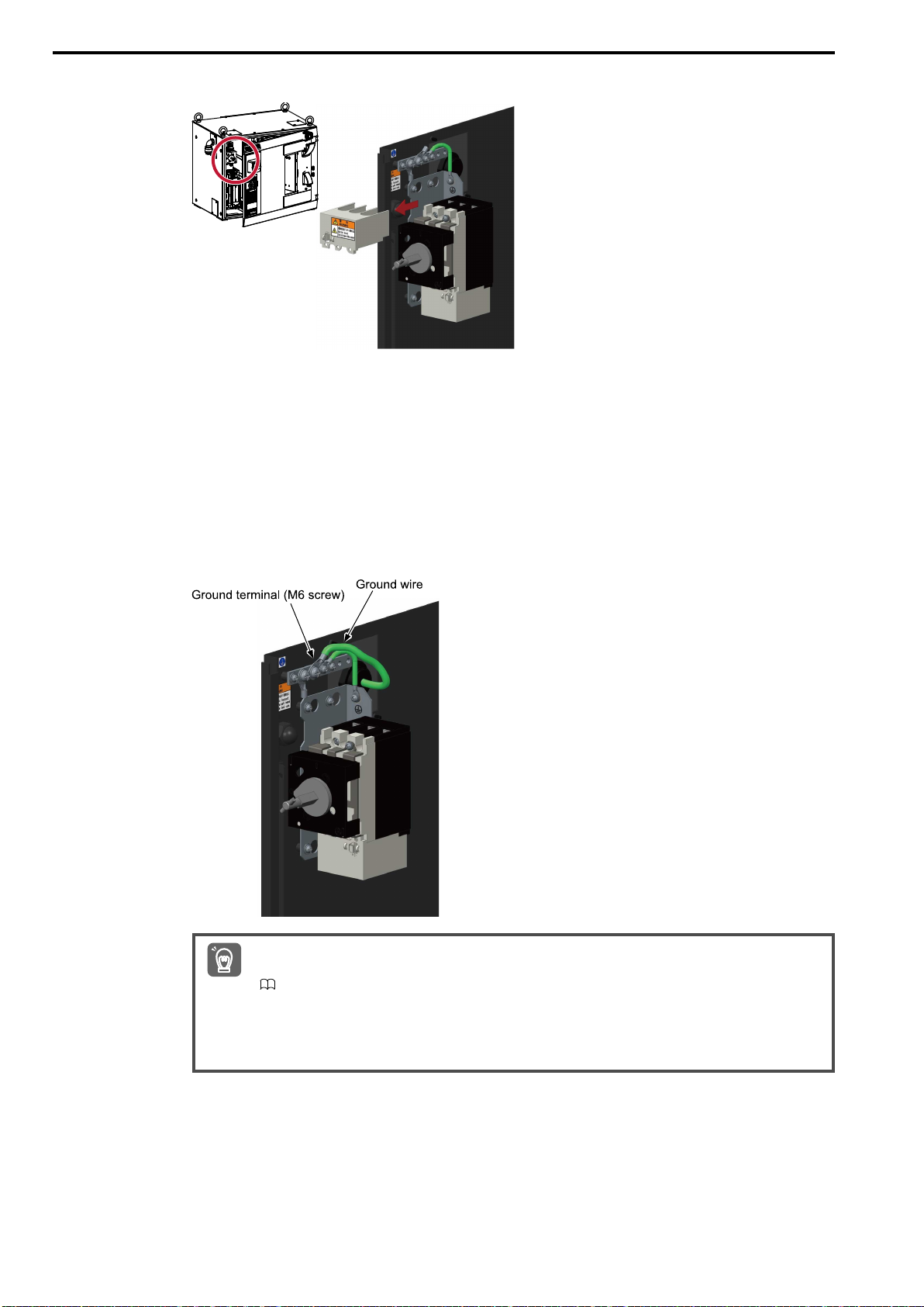
HW2480573
40/144
4. Pull the breaker cover straight off.
5. Connect the ground wire to the ground terminal (M6 screw).
Power requirement: 1.0 kVA
Cable size (for flexible cable (3 cores)): 3.5 mm
Breaker capacity: 15 A
Note:
1. The ground wire is not provided by YASKAWA.
2. Ground the robot controller to a ground resistance of 100 Ω or less in accordance with all relevant local and national electrical codes.
• Ground resistance of 100 Ω or less (200 to 240 VAC specification)
• Ground resistance of 10 Ω or less (380 to 480 VAC specification)
2
40
• Always use an earth leakage breaker for a ground resistance of 100 Ω or less. Refer to the following manual
for details.
Important
YRC1000 Instructions (Manual No.: RE-CTO-A221)
• Do not share the ground wire for the robot controller with any other ground wires or grounding electrodes,
such as those for electrical power, motors, or welders.
• Ground the robot controller in accordance with all relevant local and national electrical codes when using met-
allic ducts, metallic conduits, or cable trays to install cables.
Page 41
3.1 Connecting the YRC1000 Robot Controller and Other Devices
HW2480573
41/144
6. Connect the primary power supply.
7. Mount the breaker cover.
8. Close the robot controller door and turn the door lock 90 degrees counterclockwise.
Connecting the Robot Controller
3
41
Page 42
3.1 Connecting the YRC1000 Robot Controller and Other Devices
HW2480573
42/144
Install a dedicated breaker for the robot controller to the primary power supply.
Important
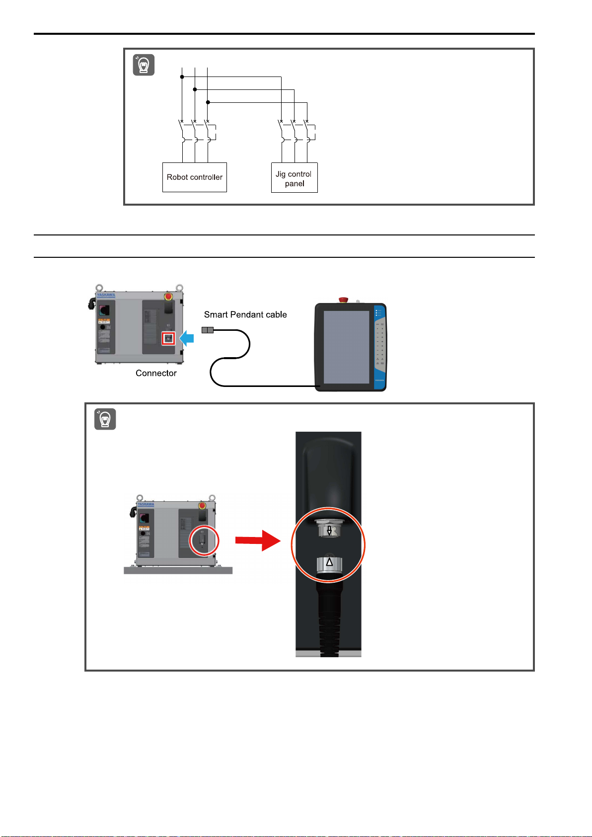
3.1.3 Connecting the Smart Pendant
Connect the Smart Pendant cable to the robot controller.
Important
Insert the cable into the connector so that the arrow on connector of the robot controller is lined up with the triangle mark
on the connector of the cable.
42
Page 43
3.2 Connecting the YRC1000micro Robot Controller and Other Devices
HW2480573
43/144
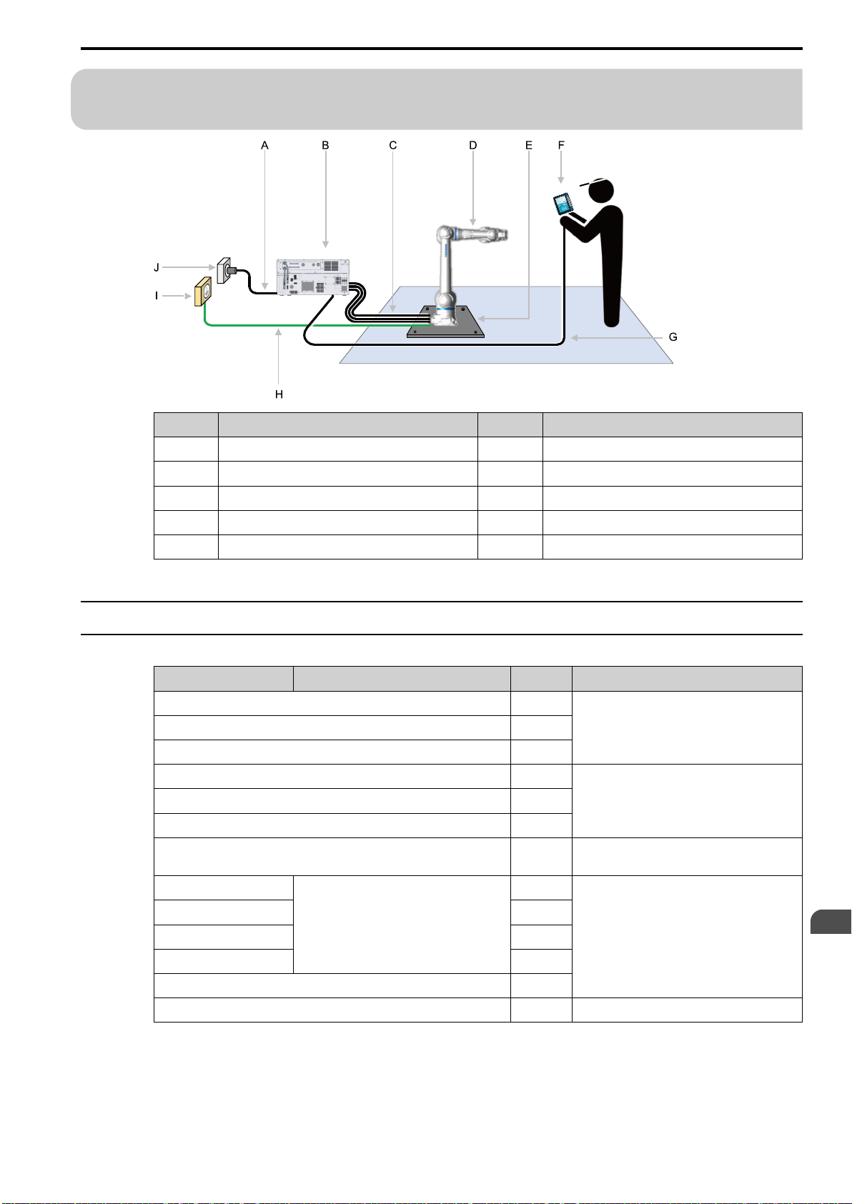
3.2 Connecting the YRC1000micro Robot Controller and
Other Devices
Symbol Name Symbol Name
A Primary power supply cable F Smart Pendant
B Robot controller G Pendant connection cable
C Manipulator cables (3 types) H Ground wire
D Manipulator I Grounding equipment (earth)
E Baseplate J Primary power supply
3.2.1 Connecting the Manipulator
Table 3.2 Required Items
Name Specifications Quantity Remarks
Manipulator cable 1 Included with the manipulator.
Torque sensor cable 1
Switch/lamp cable 1
Dummy connector for short-circuiting the safety signals 1 Included with the robot controller.
L-shaped angled plug for the primary power supply cable 1
End bell 1
Straight plug for the primary power supply cable 1 Must be purchased separately if the robot con-
Power supply cable
Cable clamp
Power outlet plug
Ground wire
*1
*1
*1
*1
Power requirement 1.0 kVA
Cable size 3.5 mm
2
troller is side mounted.
3 Robot controller circuit protector capacity: 16 A
1
1
1
Connecting the Robot Controller
3
Circuit protector 1
Phillips screwdriver 1 –
*1 Not provided by YASKAWA.
43
Page 44
3.2 Connecting the YRC1000micro Robot Controller and Other Devices
HW2480573
44/144
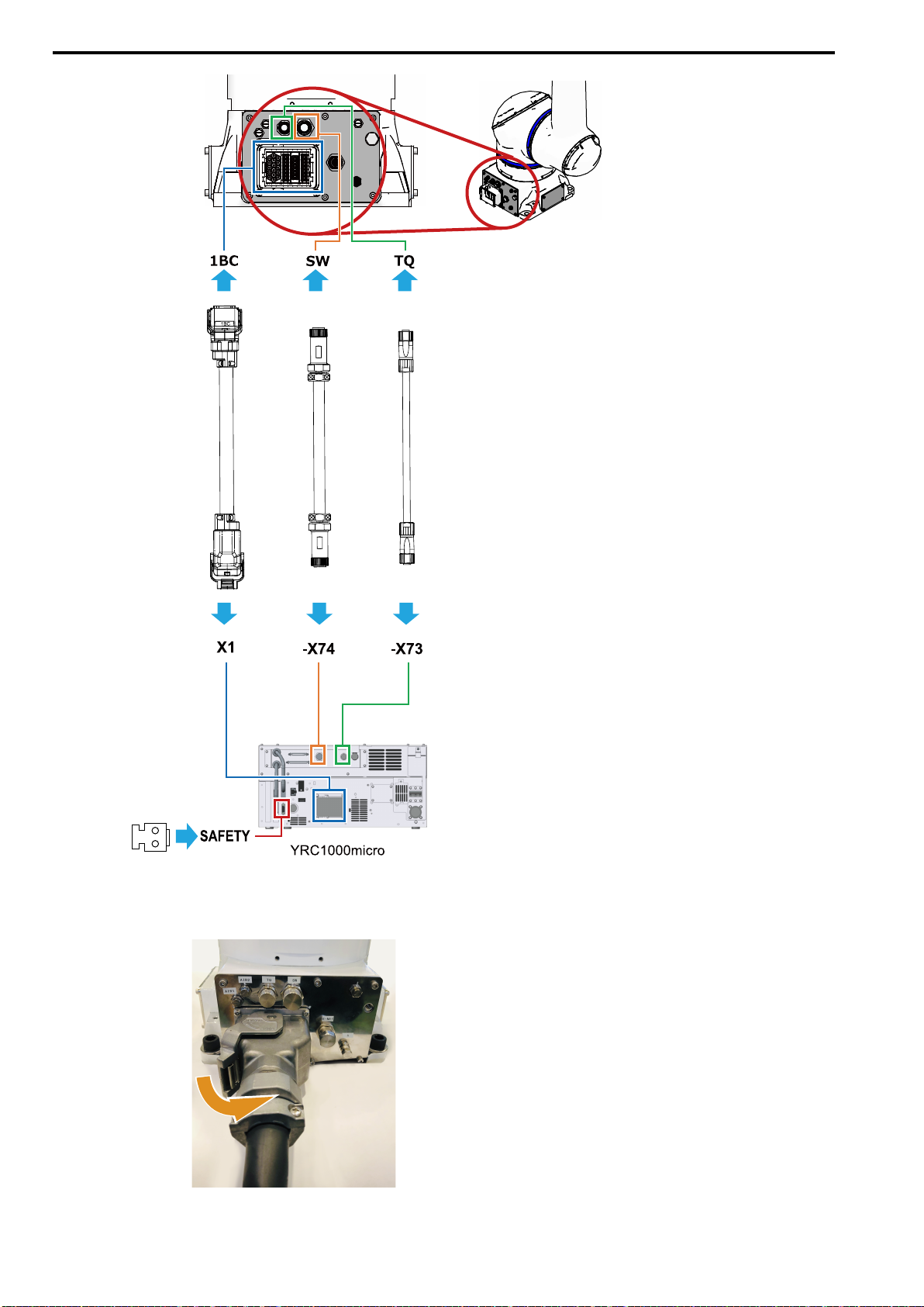
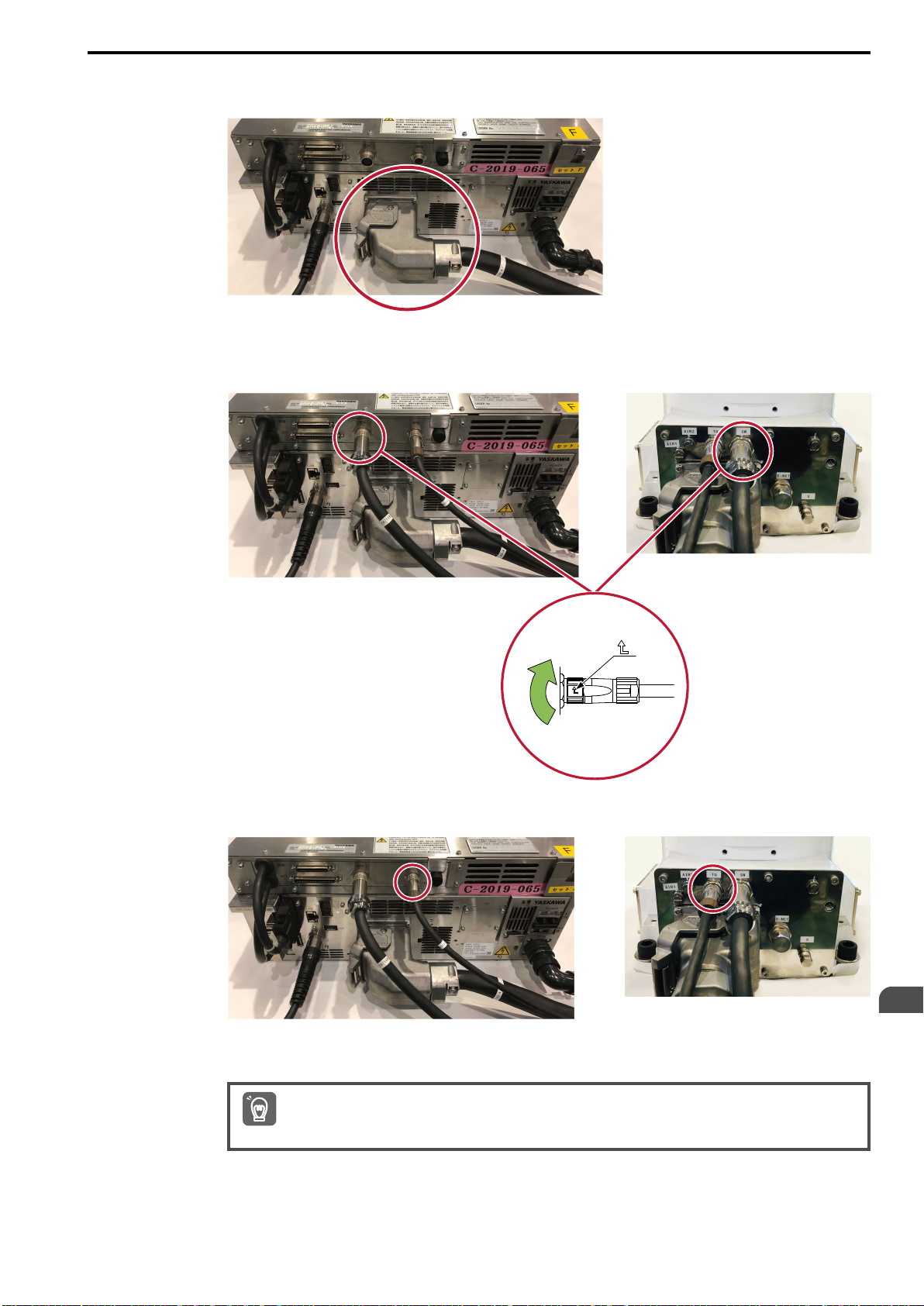
1. Connect the 1BC connector on the manipulator cable to the manipulator.
44
Insert the manipulator cable into the 1BC connector, and turn the connector lever on the manipulator
cable side to the locked position to connect the connector.
Page 45
3.2 Connecting the YRC1000micro Robot Controller and Other Devices
HW2480573
45/144
2. Use the same procedure to connect the X1 connector on the manipulator cable to the
robot controller.
3. Connect the switch/lamp cable to the [SW] connector on the manipulator and the [-X74]
connector on the robot controller.
Turn the tip of the cable connector with the arrow in the direction of the arrow to lock the cable.
4. Use the same procedure to connect the torque sensor cable to the [TQ] connector on
the manipulator and the [-X73] connector on the robot controller.
5. Connect the dummy connector for short-circuiting the safety signals to the SAFETY
connector on the robot controller.
Always connect the dummy connector for short-circuiting the safety signals. If this connector is not connected,
protective stops and external emergency stops will occur.
Important
Connecting the Robot Controller
3
45
Page 46
3.2 Connecting the YRC1000micro Robot Controller and Other Devices
HW2480573
46/144
3.2.2 Connecting the Primary Power Supply
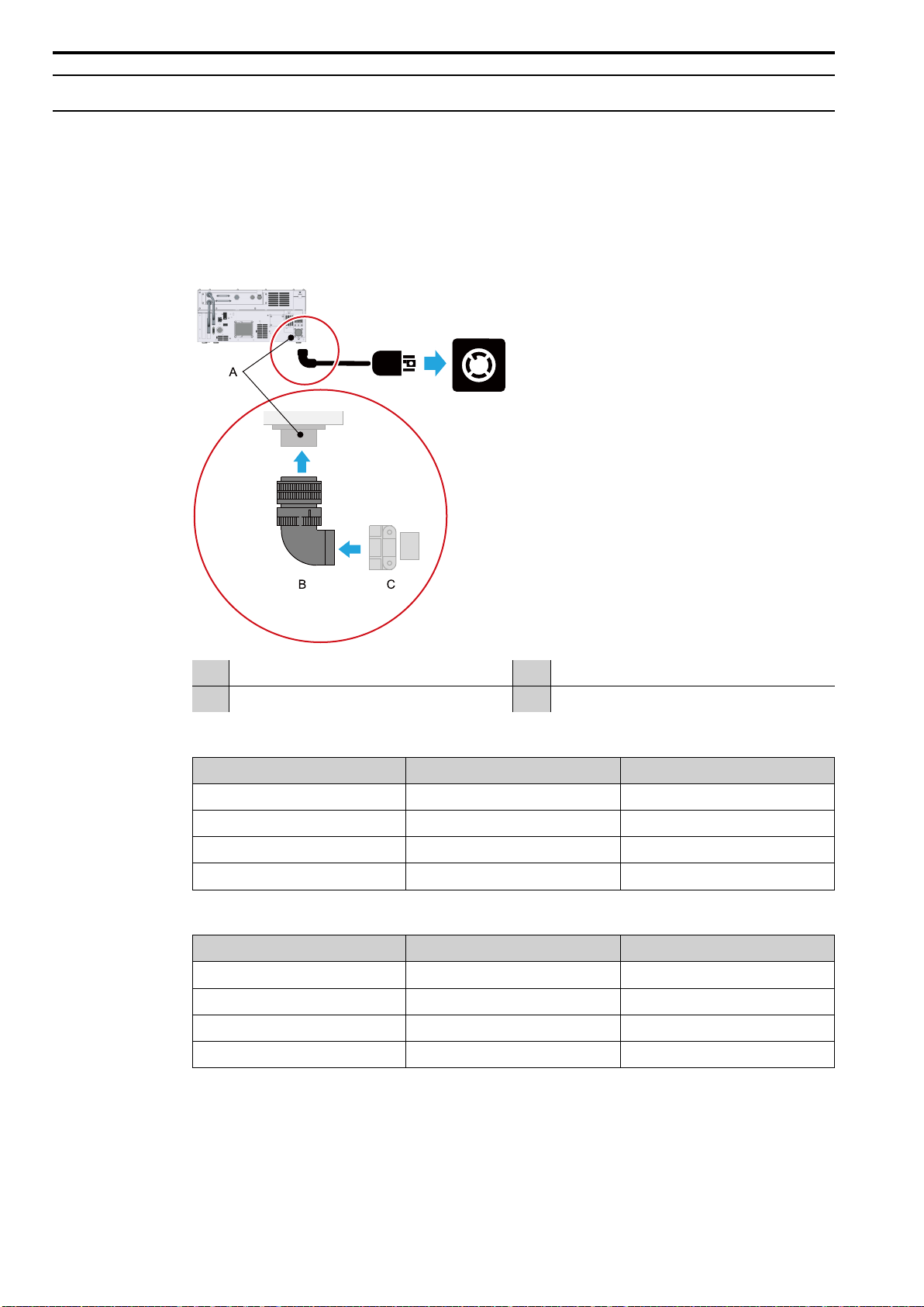
1. Connect the L-shaped angled plug for the primary power supply to the power supply
connector on the robot controller.
2. Connect the primary power supply to the robot controller.
Note:
Confirm that the circuit protector of the robot controller is turned OFF.
Note:
A straight type plug is required if the robot controller is side mounted.
A Power supply connector C Cable clamp
B L-shaped angled plug – –
Table 3.3 Power Supply Connector (ACIN) Pin Assignments on the YRC1000micro (Three-Phase
Pin No. Signal Name Description
A L1 AC input (L1/R phase)
B L2 AC input (L2/S phase)
C L3 AC input (L3/T phase)
D P.E. Protective grounding
Table 3.4 Power Supply Connector (ACIN) Pin Assignments on the YRC1000micro (Single-Phase
Pin No. Signal Name Description
A L1 AC input (L1/R phase)
B N.C. No connection
C L3 AC input (L3/T phase)
D P.E. Protective grounding
Power Supply)
Power Supply)
46
Page 47
3.2 Connecting the YRC1000micro Robot Controller and Other Devices
HW2480573
47/144
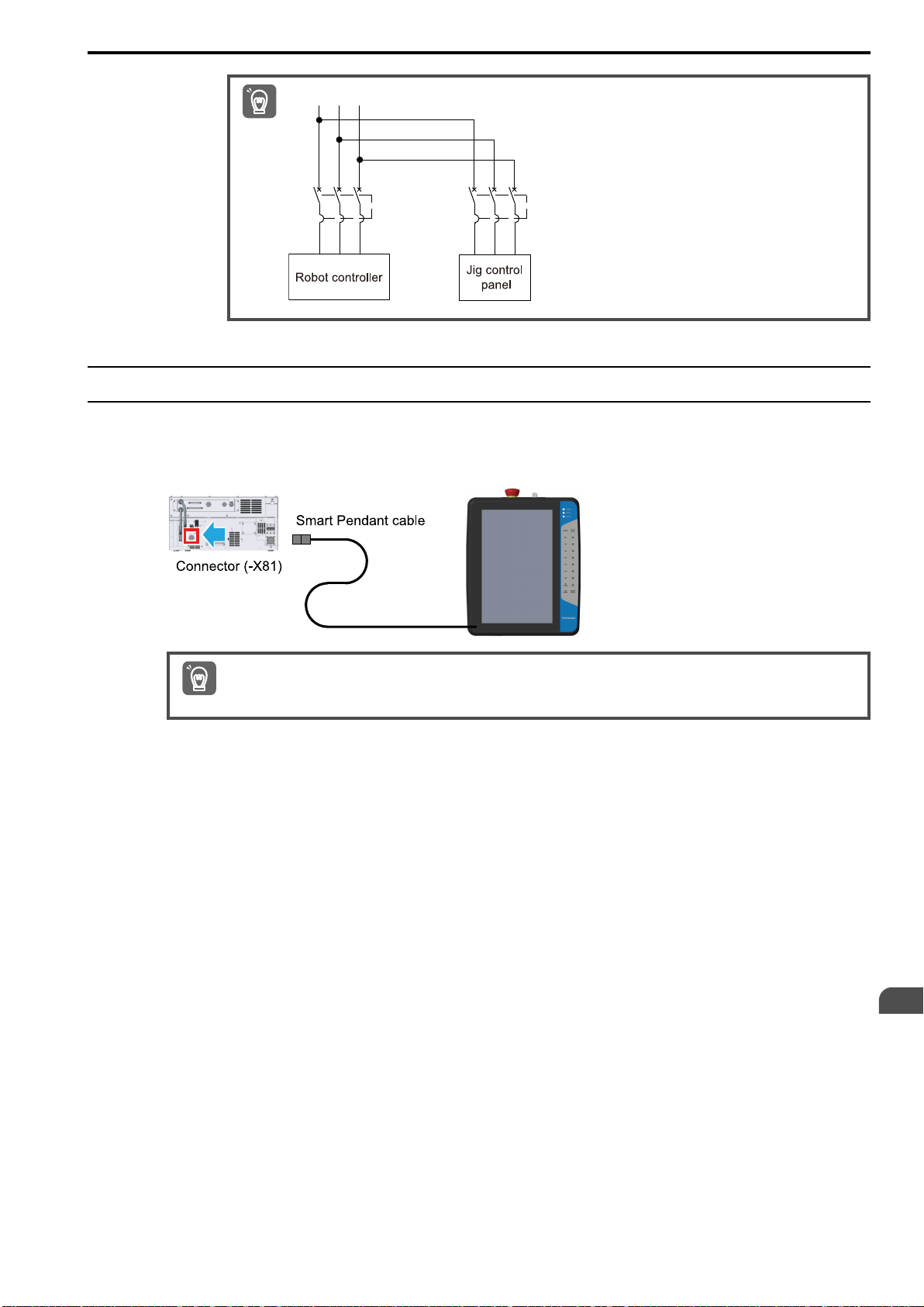
Install separate breakers for the primary power supply.
Important
3.2.3 Connecting the Smart Pendant
Connect the cable to the [-X81] connector on the robot controller.
Note:
Confirm that the pins of the robot controller and cable connectors are aligned before inserting the connector.
Important
When the Smart Pendant is not used, attach the connector for short-circuiting the Smart Pendant safety signals to the [-X81]
connector on the robot controller. The robot controller will not start if this connector is not attached.
Connecting the Robot Controller
3
47
Page 48

3.2 Connecting the YRC1000micro Robot Controller and Other Devices
HW2480573
48/144
48
Page 49

4
HW2480573
49/144
Turning ON the Robot Controller
Power Supplies
This chapter describes the how to turn ON/OFF the robot controller power supplies, how to check the
power supplies, and how to reset alarms that may occur when the power supplies are turned ON.
4.1 Turning ON/OFF and Checking the Power Supplies ....................................... 50
4.1.1 Turning ON the Main Power Supply .............................................................. 50
4.1.2 Checking Operation of the Emergency Stop Button and Servo
Power ................................................................................................................ 51
4.2 Corrective Actions for Alarms at Initial Startup ............................................... 54
4.2.1 Correcting Alarm 6022 EXTERNAL FORCE ESTIMATION ERROR and
Alarm 6004 ESCAPE FROM CLAMPING ERROR(PFL)................................ 54
4.2.2 Correcting Alarm 4107 OUT OF RANGE(ABSO DATA)................................ 56
49
Page 50
4.1 Turning ON/OFF and Checking the Power Supplies
HW2480573
50/144
4.1 Turning ON/OFF and Checking the Power Supplies
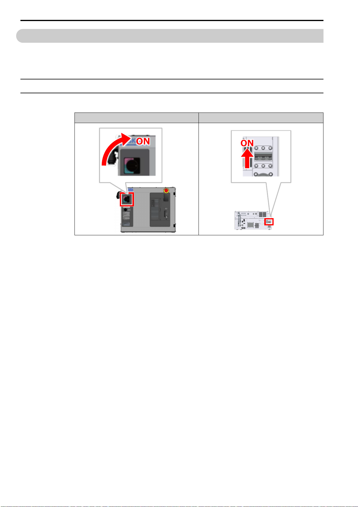
The main power supply and servo power are required to move the manipulator. Before moving the manipulator,
first turn ON/OFF these power supplies and check the correct operation of the emergency stop button.
4.1.1 Turning ON the Main Power Supply
1. Turn ON the main power supply to the robot controller.
YRC1000 YRC1000micro
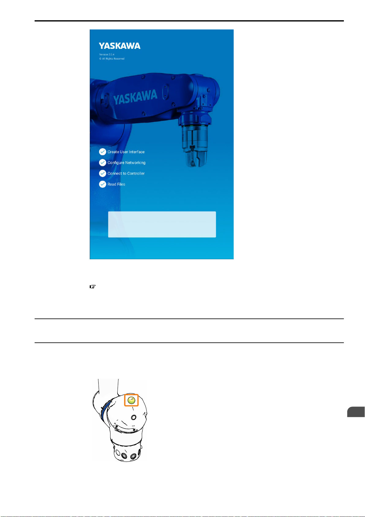
2. Confirm that the startup window is displayed on the Smart Pendant.
It will take approximately three minutes until the window is displayed.
50
Page 51
4.1 Turning ON/OFF and Checking the Power Supplies
HW2480573
51/144
The main power supply is working correctly when the startup window is displayed.
Refer to the following section if an alarm is displayed on the Smart Pendant.
4.2 Corrective Actions for Alarms at Initial Startup on page 54
This concludes the procedure.
4.1.2 Checking Operation of the Emergency Stop Button and Servo
Power
Confirm the operation to turn ON/OFF the servo power, and confirm that the servo power is canceled when the
emergency stop button is pressed.
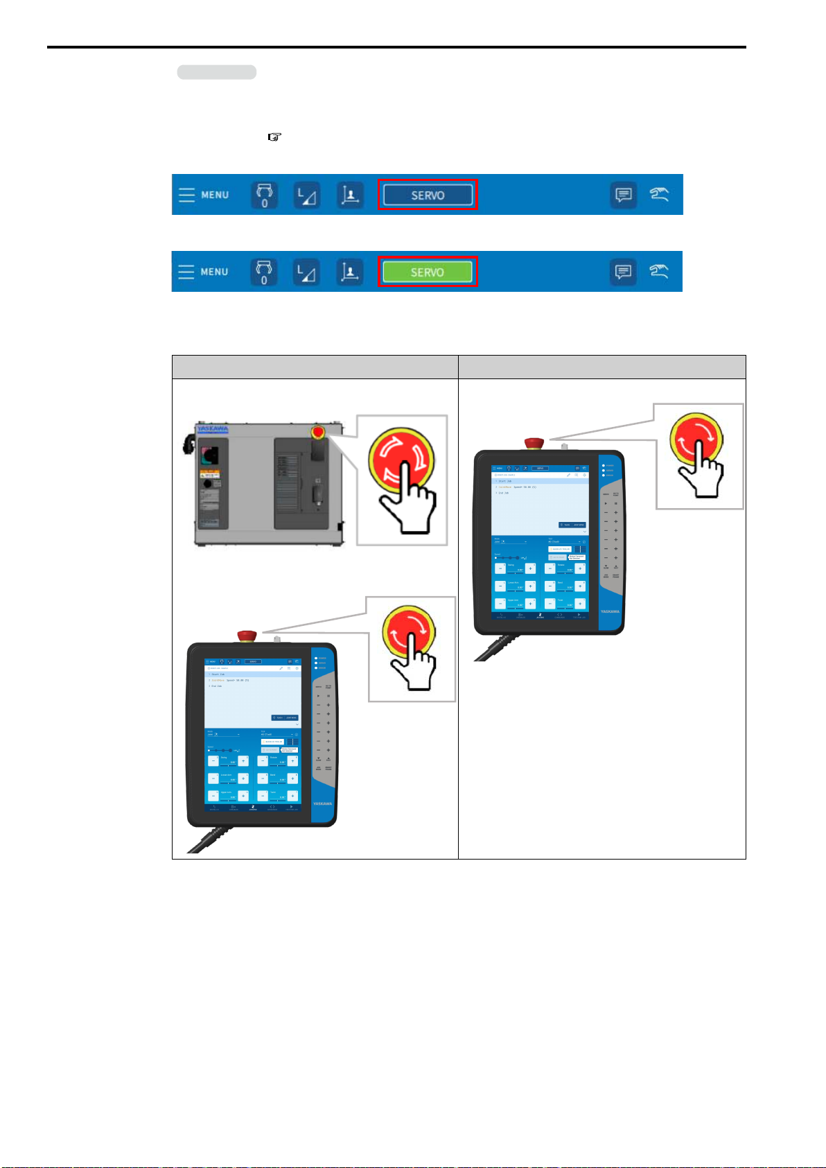
1. Confirm that the collaborative operation LED on the manipulator is lit in green.
Turning ON the Robot Controller Power Supplies
4
51
Page 52
4.1 Turning ON/OFF and Checking the Power Supplies
HW2480573
52/144
Information
• A green lit LED means collaborative operation is enabled. Enabled is the default setting. If the LED is not
lit, the subsequent operations cannot be performed.
• When using the YRC1000micro robot controller, protective stop and external emergency stop alarms will
occur if the connector for short-circuiting the safety signals is not connected to the robot controller. Refer to
the following section for details.
1.2.1 Components in a Basic Robot System on page 17
2. Tap {SERVO} to turn ON the servo.
3. Confirm that the servo power is turned ON and {SERVO} is green.
The correct operation of servo power ON can be confirmed.
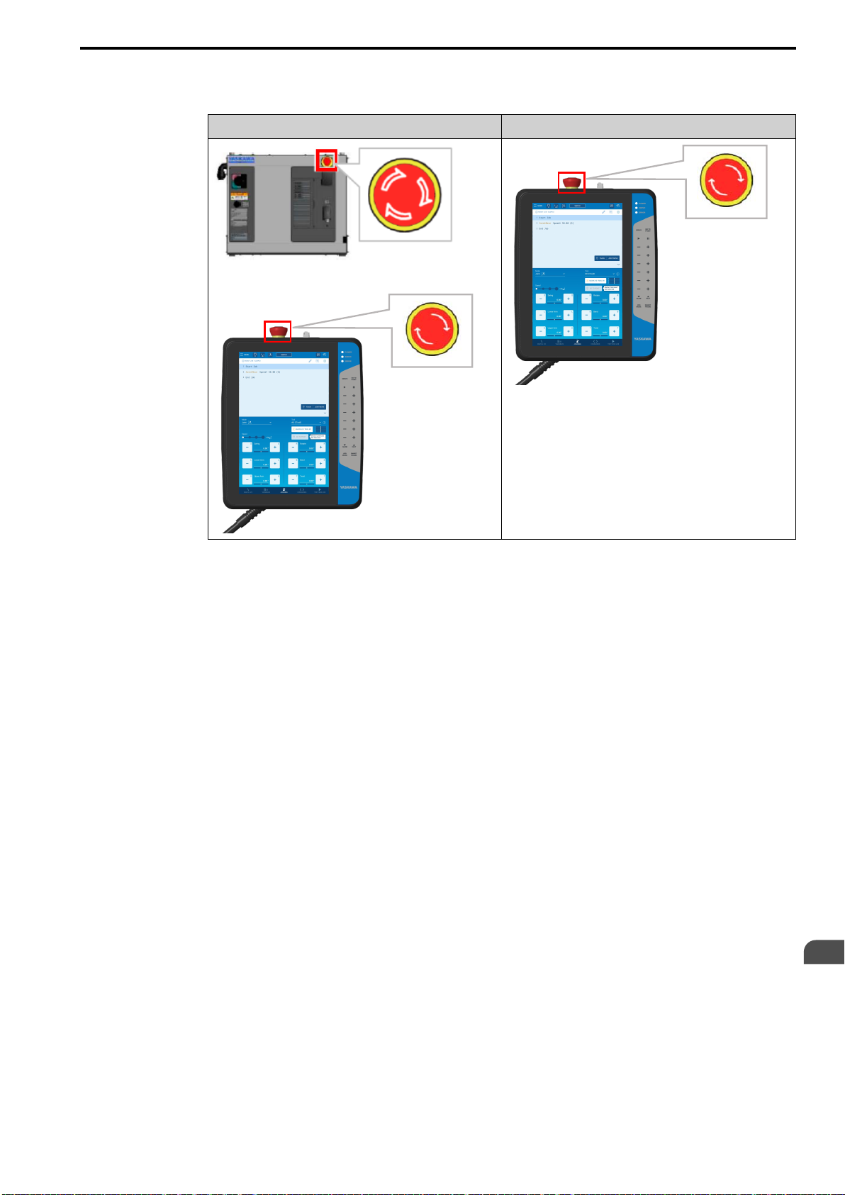
4. Press the emergency stop button.
YRC1000 YRC1000micro
There is an emergency stop button on the YRC1000.
There is an emergency stop button on the Smart Pendant.
The emergency stop button on the Smart Pendant can also be
used.
5. Confirm that {SERVO} changes back to blue.
A blue {SERVO} means the servo power has been turned OFF.
Note:
The YRC1000micro is not equipped with an emergency stop
button.
52
Page 53
4.1 Turning ON/OFF and Checking the Power Supplies
HW2480573
53/144
6. Turn the emergency stop button in the direction of the arrows to reset the emergency
stop.
YRC1000 YRC1000micro
or
This concludes the procedure.
Turning ON the Robot Controller Power Supplies
4
53
Page 54
4.2 Corrective Actions for Alarms at Initial Startup
HW2480573
54/144
4.2 Corrective Actions for Alarms at Initial Startup
The following alarms may occur when the manipulator is first started.
If the following alarms occur, take the corrective actions described in the reference section.
Alarm No. Alarm Name Possible Cause Reference Section
• A large force was applied when the power supply to the
6022
6004
4107
EXTERNAL FORCE ESTIMATION ERROR
ESCAPE FROM CLAMPING ERROR(PFL)
OUT OF RANGE(ABSO
DATA)
Escape Operation :
The operation in which the manipulator automatically moves in a safe direction from a clamped state.
Term
robot controller was turned ON.
• The home positions of the torque sensors have greatly
deviated.
• The manipulator cannot perform the escape operation
because a large force was applied when the power supply
to the robot controller was turned ON.
• The manipulator cannot perform the escape operation
because the home positions of the torque sensors have
greatly deviated.
• The motor axis became misaligned when the power sup-
ply was turned OFF.
• There is a difference that exceeds the allowable range in
the position of the motor axis when the power supply
was turned OFF and when it was turned ON.
4.2.1 Correcting Alarm
6022 EXTERNAL
FORCE ESTIMATION
ERROR and Alarm 6004
ESCAPE FROM
CLAMPING ERROR
(PFL) on page 54
4.2.2 Correcting Alarm
4107 OUT OF RANGE
(ABSO DATA) on page
56
4.2.1 Correcting Alarm 6022 EXTERNAL FORCE ESTIMATION ERROR
and Alarm 6004 ESCAPE FROM CLAMPING ERROR(PFL)
Use the following procedure to reset alarm 6022 EXTERNAL FORCE ESTIMATION ERROR or alarm 6004
ESCAPE FROM CLAMPING ERROR(PFL) that occurs when the manipulator is first started.
Information
(1) Reset the Alarm
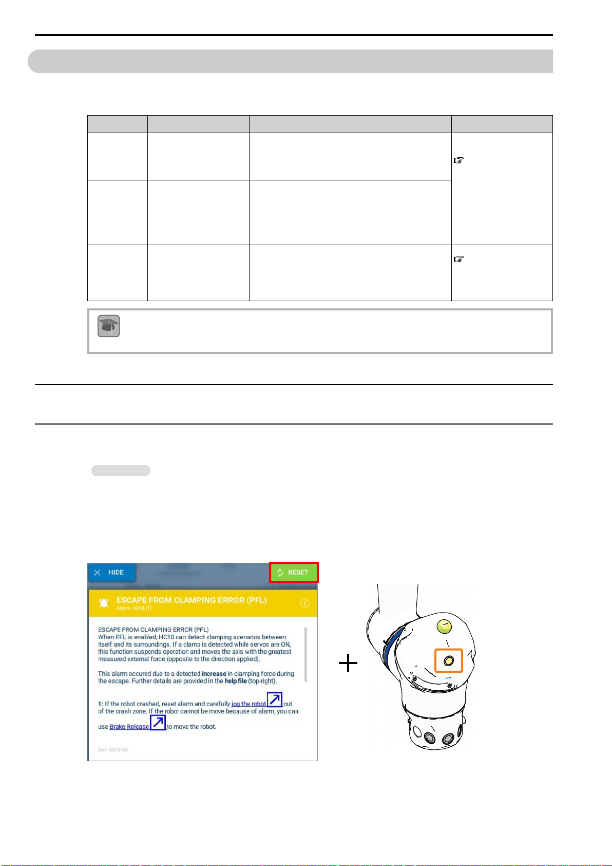
If an alarm occurs, the ERROR lamp on the Smart Pendant will be lit, an alarm window similar to the following
will be displayed, and the resume switch will be lit.
Select {RESET} to reset the alarm.
If multiple alarms occur, use this procedure to reset both alarm 6022 and alarm 6004 in a single operation.
54
Page 55
4.2 Corrective Actions for Alarms at Initial Startup
HW2480573
55/144
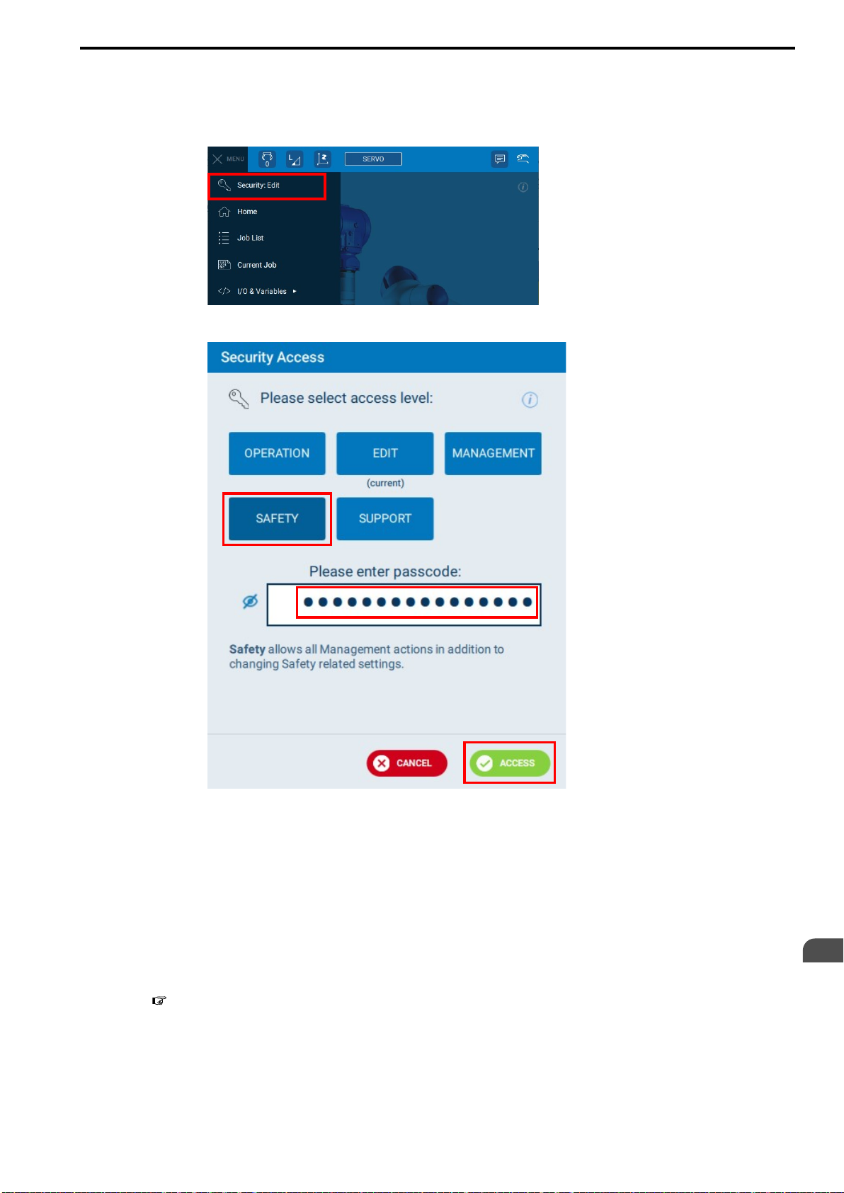
(2) Change Security to {Safety}
To change the home position settings of the torque sensors, change the security access level to {Safety}.
1. From the status bar, select {MENU} - {Security: Edit}.
2. On the Security Access window, tap {SAFETY}.
(3) Set the Home Positions of the Torque Sensors Again
If the home positions of the torque sensors have deviated, such as due to receiving a large shock, erroneous
detections will occur, such as a small external force being detected as a large external force.
To prevent erroneous detections, set the home positions of the torque sensors again.
Refer to the following section for the procedure to set the home positions of the torque sensors again.
When the home position of the torque sensor is set again, press the resume switch on the manipulator.
3. Enter the password and tap {ACCESS}.
Note:
The default password is set to "5555555555555555" (enter "5" 16 times).
Turning ON the Robot Controller Power Supplies
4
7.3.2 Setting the Home Positions of the Torque Sensors Again on page 99
55
Page 56
4.2 Corrective Actions for Alarms at Initial Startup
HW2480573
56/144
This concludes the procedure.
4.2.2 Correcting Alarm 4107 OUT OF RANGE(ABSO DATA)
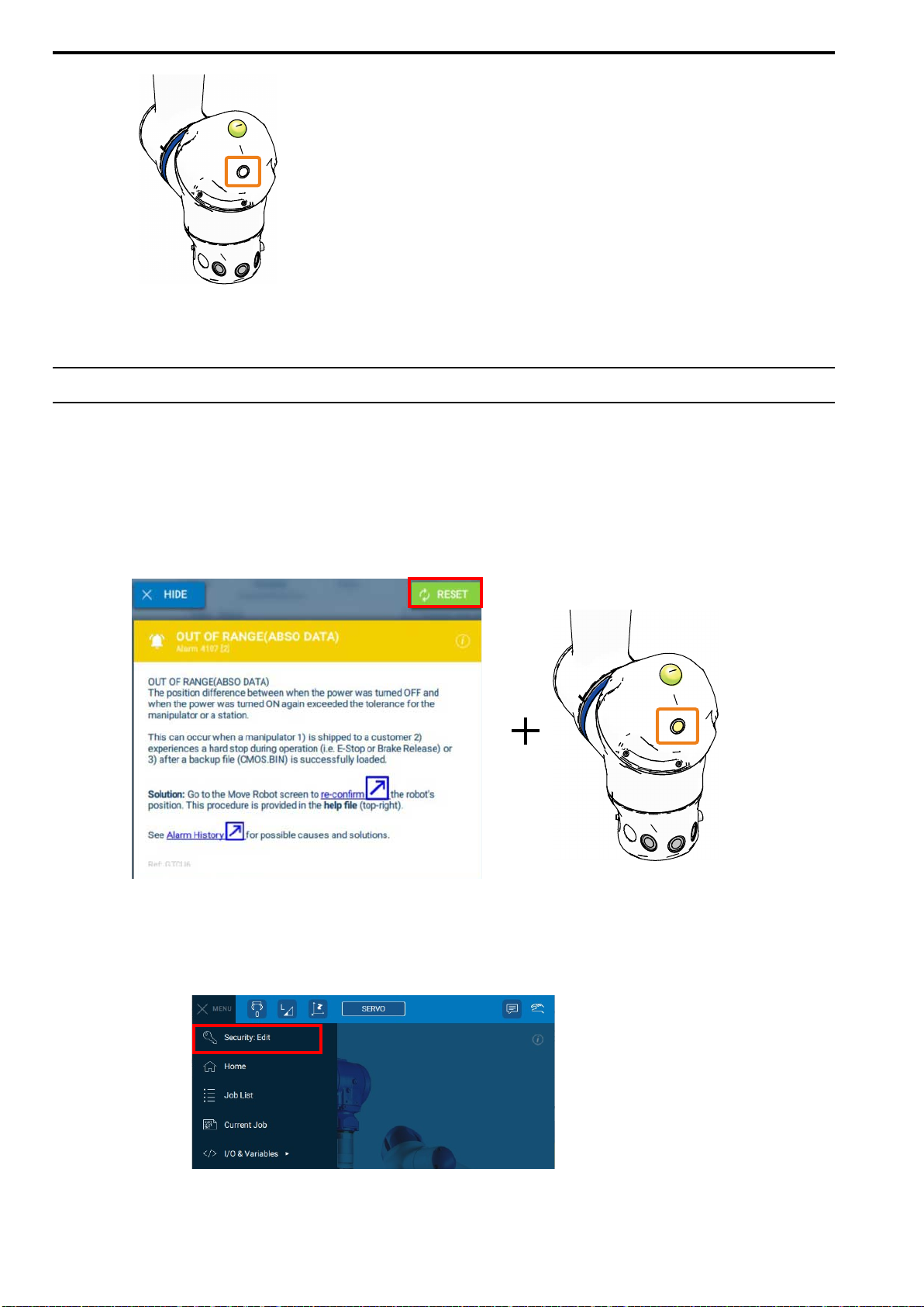
Use the following procedure to reset alarm 4107 OUT OF RANGE(ABSO DATA) that occurs when the manipulator is first started.
(1) Reset the Alarm
If an alarm occurs, the ERROR lamp on the Smart Pendant will be lit, an alarm window similar to the following
will be displayed, and the resume switch will be lit.
Select {RESET} to reset the alarm.
(2) Change Security to {SAFETY}
To confirm the position of the manipulator, change the security access level to {SAFETY}.
1. From the status bar, select {MENU} - {Security: Edit}.
56
Page 57
4.2 Corrective Actions for Alarms at Initial Startup
HW2480573
57/144
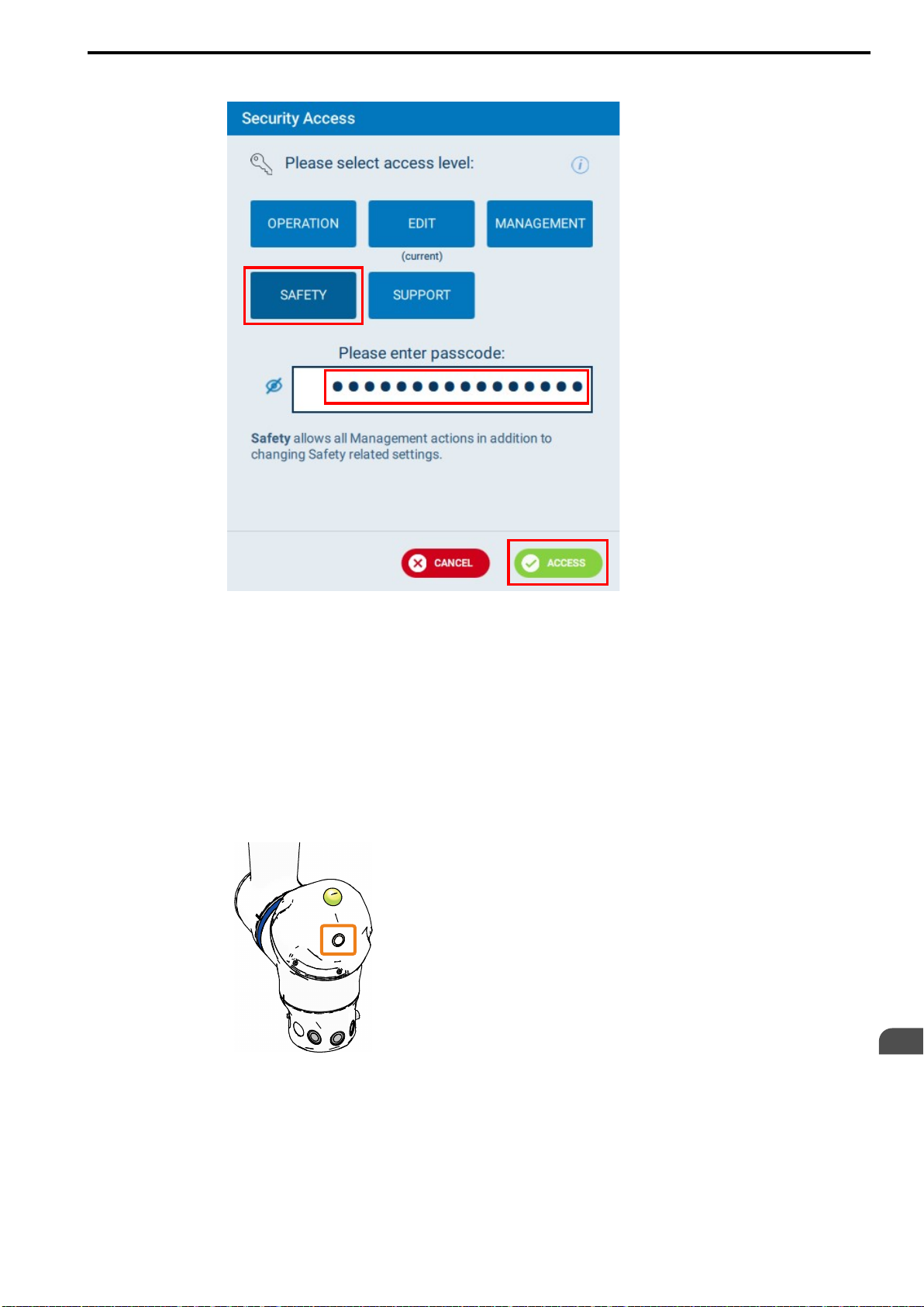
2. On the Security Access window, tap {SAFETY}.
3. Enter the password and tap {ACCESS}.
Note:
The default password is set to "5555555555555555" (enter "5" 16 times).
(3) Confirm the Position of the Manipulator
In the current state, there is a large difference between the position of the manipulator when the power supply
was turned OFF and when the power supply was turned ON. The alarm occurred because of this difference in
positions.
Confirm the position according to the rest of this procedure to eliminate this difference.
1. If the resume switch on the manipulator is lit, press the resume switch.
Turning ON the Robot Controller Power Supplies
4
57
Page 58
4.2 Corrective Actions for Alarms at Initial Startup
HW2480573
58/144
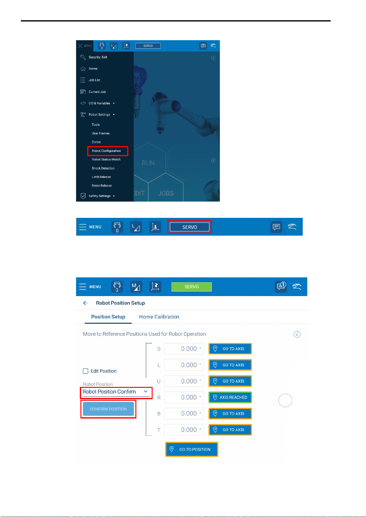
2. From the status bar, select {MENU} - {Robot Settings} - {Robot Configuration}.
3. Tap {SERVO} on the status bar to turn ON the servo.
The button will turn green when the servo is turned ON.
4. Confirm that {Robot Position Confirm} is selected.
{CONFIRM POSITION} will be displayed and the orange box will flash. However, this will be disabled if the robot position is incorrect.
58
Page 59
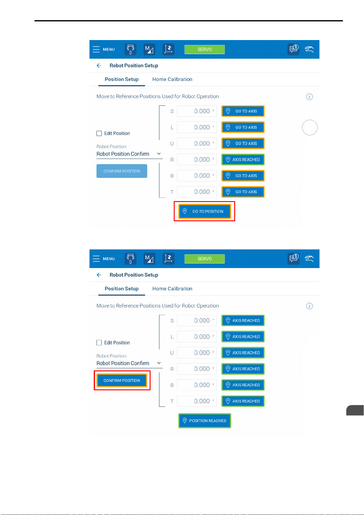
5. Press and hold {GO TO POSITION}.
HW2480573
59/144
4.2 Corrective Actions for Alarms at Initial Startup
When the robot moves to and reaches the confirmed position, {CONFIRM POSITION} will be
enabled.
Turning ON the Robot Controller Power Supplies
4
59
Page 60
4.2 Corrective Actions for Alarms at Initial Startup
HW2480573
60/144
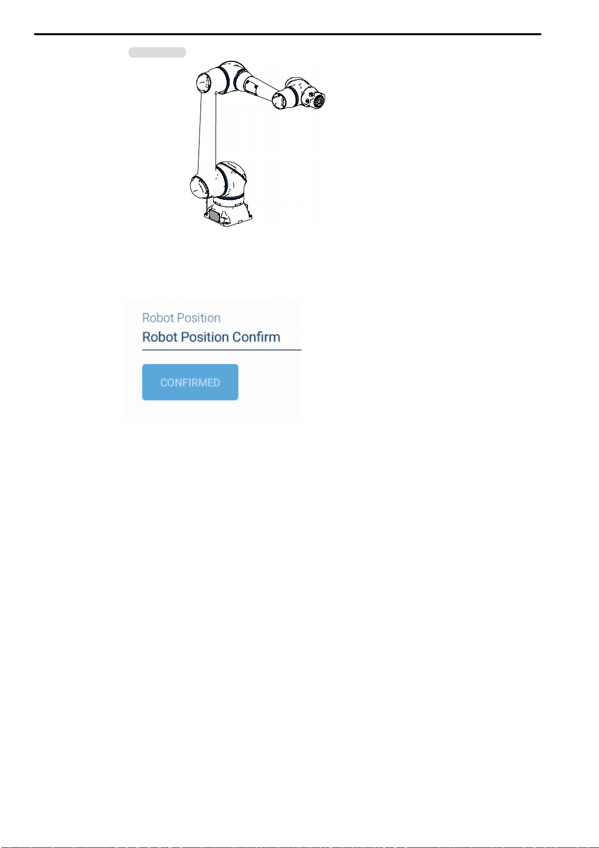
Information
The manipulator will automatically stop at the second home position posture.
The second home position posture is shown below.
6. Tap {CONFIRM POSITION}.
The robot position will be confirmed and a confirmation message will be displayed.
7. Confirm that the confirmation message was displayed.
This concludes the procedure. Jobs can be run and the operations to move to previous teaching points can be
used again.
60
Page 61

5
HW2480573
61/144
Controlling the Manipulator
This chapter describes jogging operations to move manipulator axes and direct teach operations to store
operating positions in the manipulator.
5.1 Moving the Manipulator ..........................................................................................62
5.1.1 Jogging Each Axis .......................................................................................... 62
5.1.2 Jogging Parallel to the TCP............................................................................ 65
5.1.3 Direct Teach ..................................................................................................... 67
61
Page 62
5.1 Moving the Manipulator
HW2480573
62/144
5.1 Moving the Manipulator
This section describes the basic operations to move the manipulator.
Operation Menu Name Description Reference Section
Jogging Each Axis Joint
Jogging Parallel to the
TCP
Direct Teach Hand Guiding
World
5.1.1 Jogging Each Axis
Jogging is the most basic manipulator operation.
Use the following procedure to move the desired axis of the manipulator.
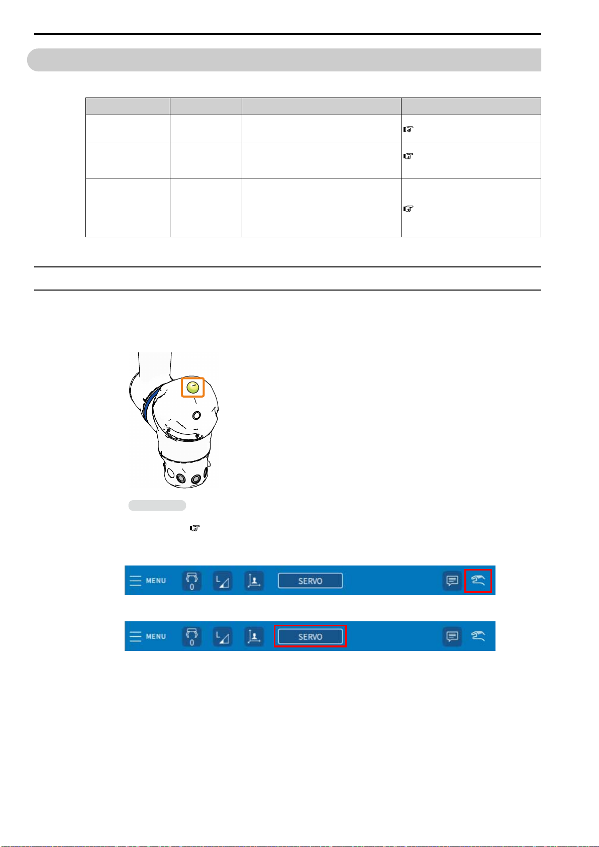
1. Confirm that the collaborative operation lamp is lit in green.
The operation to move each axis of the manipulator independently.
The operation to move in parallel to the X-axis,
Y-axis, and Z-axis that are defined based on the
manipulator.
The operation to manually move the manipulator to the desired position and store that
position.
The manipulator achieves continuous motion
by moving between the recorded positions.
5.1.1 Jogging Each Axis on page 62
5.1.2 Jogging Parallel to the TCP
on page 65
5.1.3 Direct Teach on page 67
Information
If the lamp is not lit, the collaborative operation function is disabled. Refer to the following section and enable the collaborative operation function.
7.6 Enabling the Collaborative Operation Function on page 111
2. Change the mode switch to MANUAL (TEACH) mode, and set the operation mode to
teach mode.
3. Tap {SERVO} on the status bar to turn ON the servo.
The button will turn green when the servo is turned ON.
62
Page 63
5.1 Moving the Manipulator
HW2480573
63/144
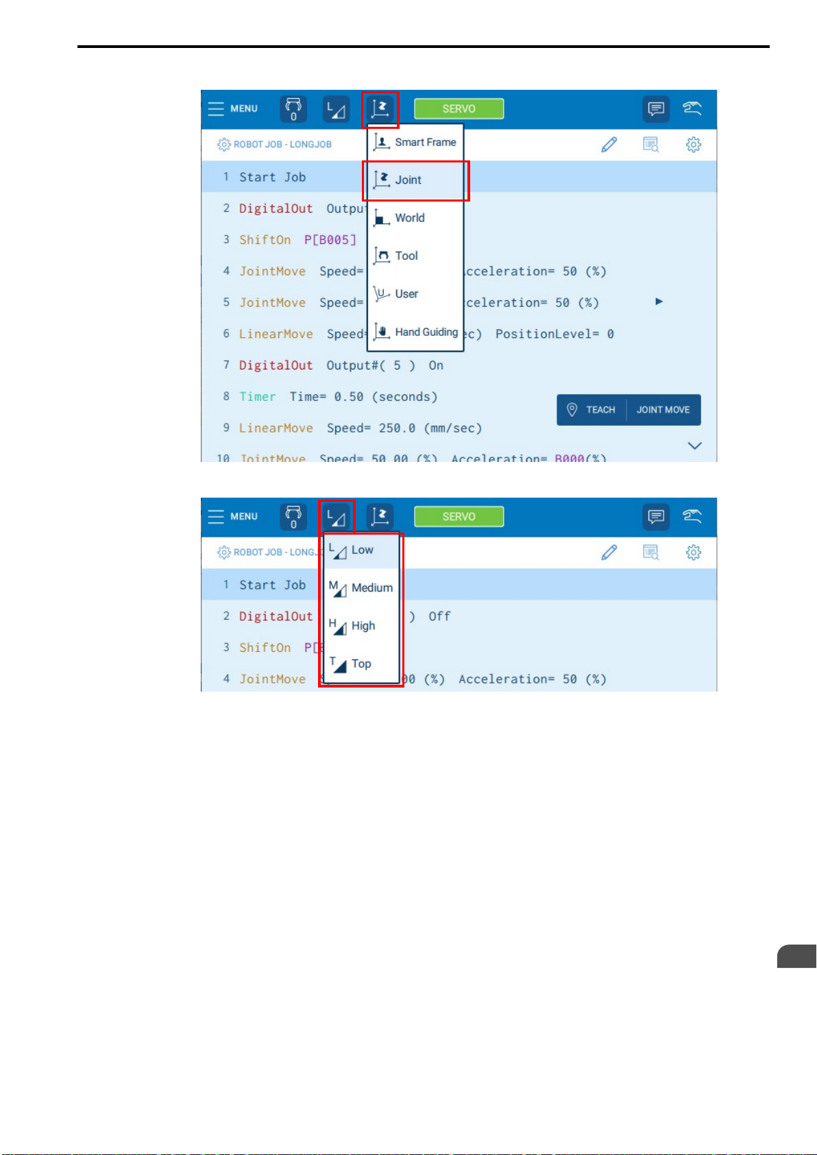
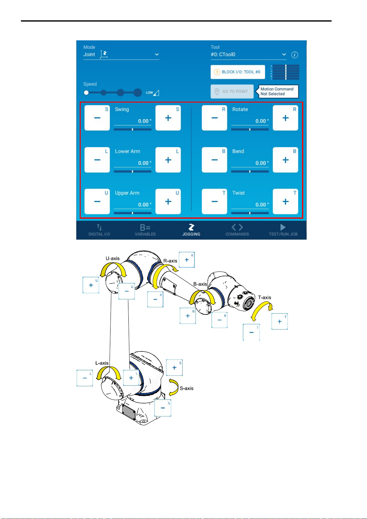
4. Tap the operation mode icon on the status bar and select {Joint}.
5. Tap the operation speed icon on the status bar and select the operation speed.
Controlling the Manipulator
5
63
Page 64
5.1 Moving the Manipulator
HW2480573
64/144
6. Press the jog keys on the programming panel to move the manipulator.
This concludes the procedure.
64
Page 65
5.1.2 Jogging Parallel to the TCP
HW2480573
65/144
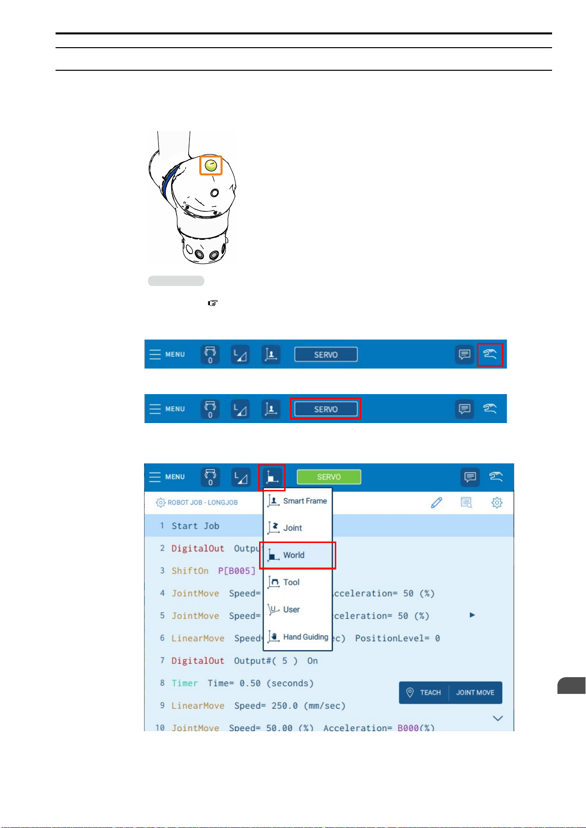
The tip of the manipulator moves in parallel to the X-axis, Y-axis, and Z-axis set for the manipulator base.
Use the following procedure to move the tip of the manipulator in the desired direction.
1. Confirm that the collaborative operation lamp is lit in green.
5.1 Moving the Manipulator
Information
If the lamp is not lit, the collaborative operation function is disabled. Refer to the following section and enable the collaborative operation function.
7.6 Enabling the Collaborative Operation Function on page 111
2. Change the mode switch to MANUAL (TEACH) mode, and set the operation mode to
teach mode.
3. Tap {SERVO} on the status bar to turn ON the servo.
The button will turn green when the servo is turned ON.
4. Tap the operation mode icon on the status bar and select {World}.
Controlling the Manipulator
5
65
Page 66
5.1 Moving the Manipulator
HW2480573
66/144
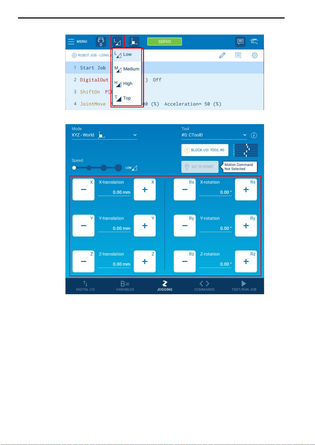
5. Tap the operation speed icon on the status bar and select the operation speed.
6. Press the jog keys on the programming panel to move the manipulator.
66
Page 67
5.1 Moving the Manipulator
HW2480573
67/144
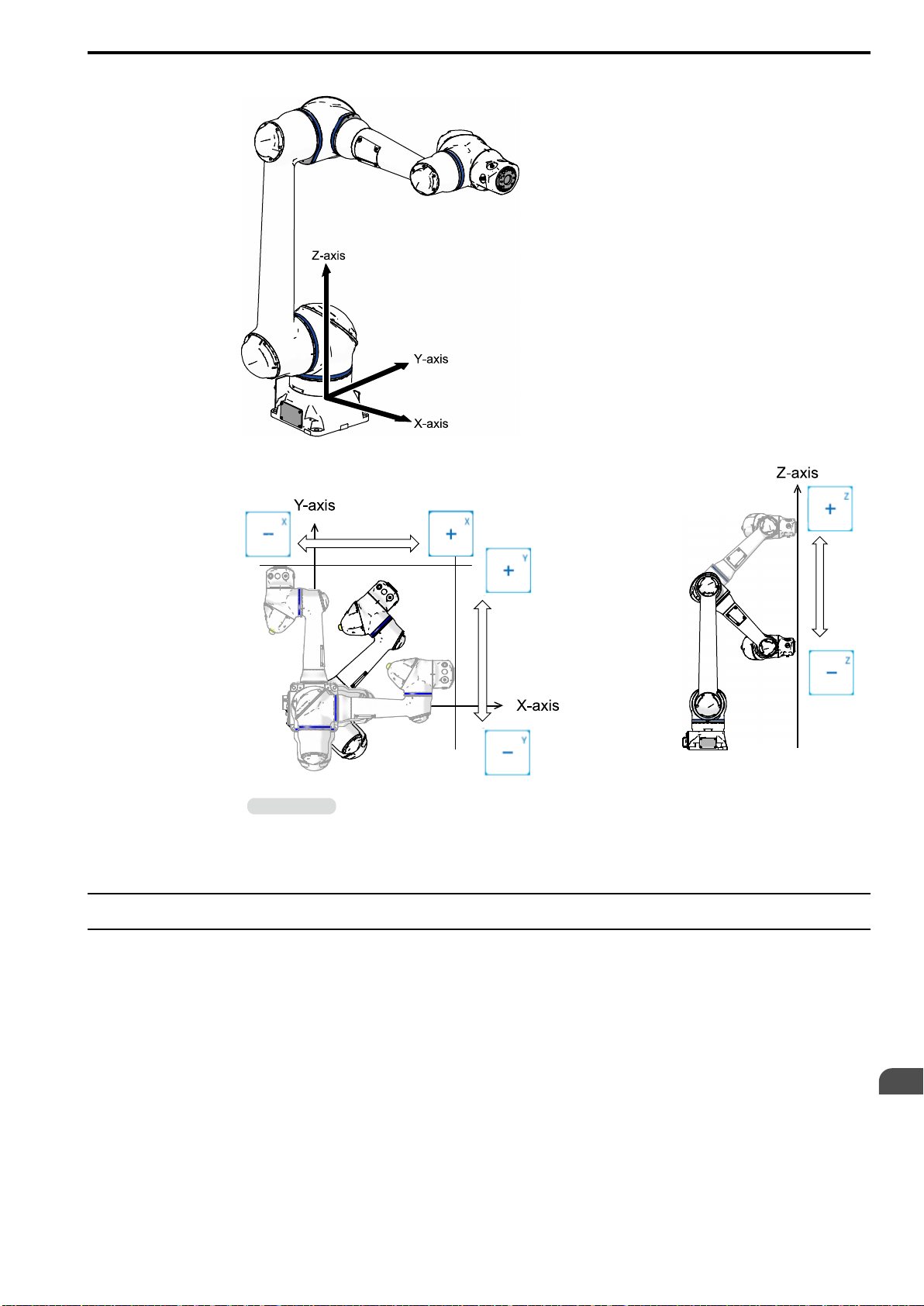
• X-Axis, Y-Axis, and Z-Axis Directions That Are Defined Based on the Manipulator
• Relationship between Smart Pendant Jog Keys and Manipulator Movement
Information
This concludes the procedure.
5.1.3 Direct Teach
Hand guiding mode is the operation to manually move the manipulator to the desired position and store that position. For hand guiding mode, select {XYZ + TOOL}. The manipulator can be manually moved in the X, Y, and
Z directions.
The illustration on the left is the view from directly above the manipulator.
Controlling the Manipulator
5
67
Page 68
5.1 Moving the Manipulator
HW2480573
68/144
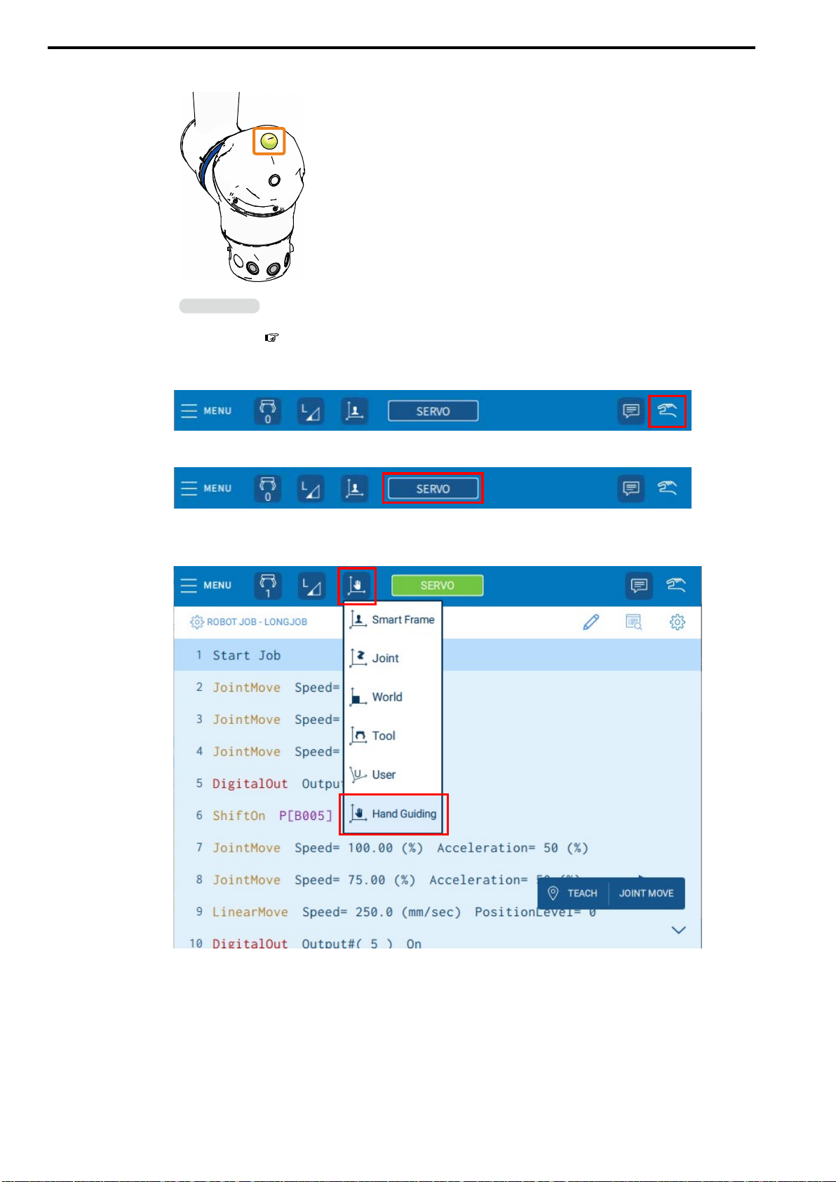
1. Confirm that the collaborative operation LED is lit in green.
Information
If the LED is not lit, the collaborative operation function is disabled. Refer to the following section and enable the collaborative operation function.
7.6 Enabling the Collaborative Operation Function on page 111
2. Change the mode switch to MANUAL (TEACH) mode, and set the operation mode to
teach mode.
3. Tap {SERVO} on the status bar to turn ON the servo.
The button will turn green when the servo is turned ON.
4. Tap the operation mode icon on the status bar and select {Hand Guiding}.
68
Page 69
5.1 Moving the Manipulator
HW2480573
69/144
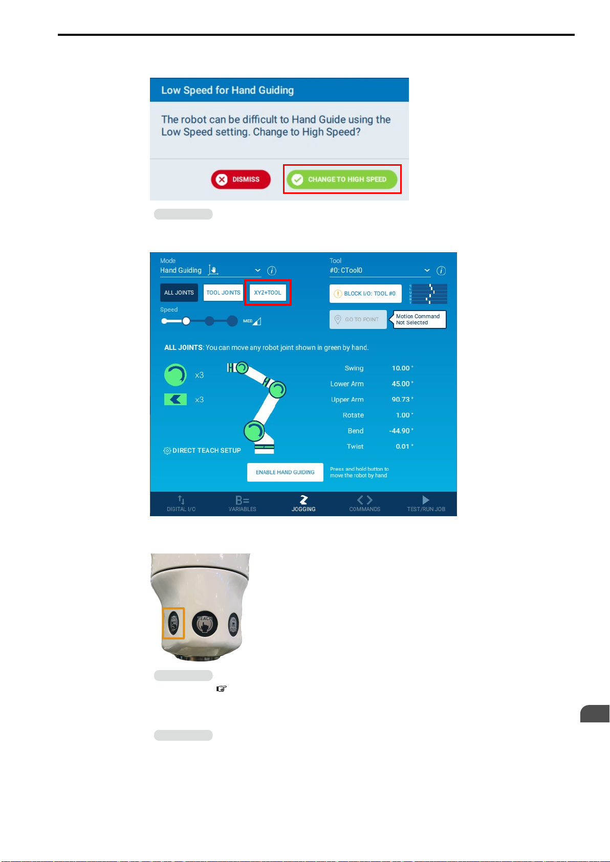
5. If the operation speed is set to low speed, the following message will be displayed.
Select {CHANGE TO HIGH SPEED}.
Information
If set to low speed, teaching precision will fall because a strong force will be required to manually move the
manipulator. An alarm will occur if the manipulator is pushed too hard.
6. Select {XYZ + TOOL}.
7. Confirm that the manipulator can be manually moved while the [MOVE] button on the
manipulator is pressed.
Information
Refer to the following section for details on creating a program (registering a job).
8.2.1 Creating a Program on page 117
8. While the [MOVE] button on the manipulator is pressed, manually move the arm of the
manipulator to the location to be taught.
Information
If the arm speed feels fast, tap the [MOVE] button twice (double-click), and then move the arm when all
three buttons are flashing. The arm will move slowly, and it will be easier to make fine adjustments because
the feeling of arm coasting will be reduced.
9. Release the [MOVE] button on the manipulator.
Controlling the Manipulator
5
69
Page 70
5.1 Moving the Manipulator
HW2480573
70/144
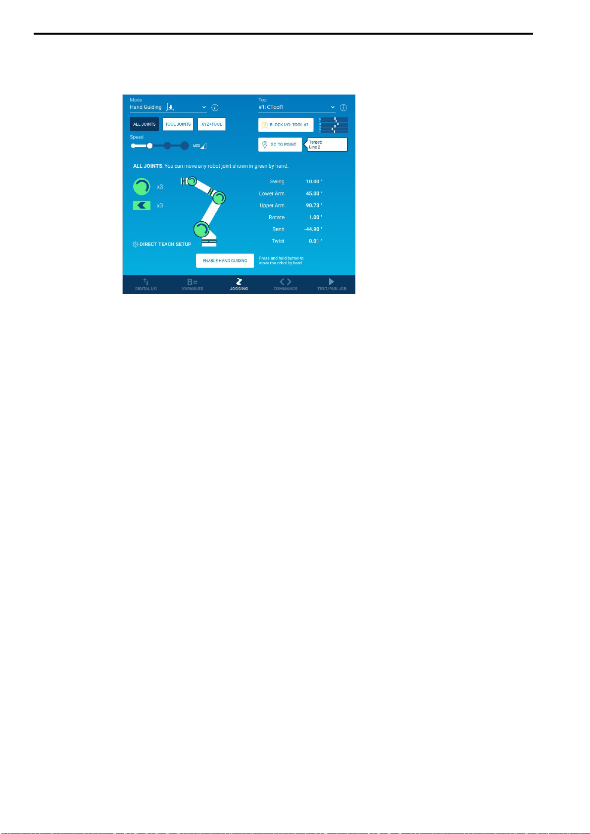
10. Press the [TEACH] button on the manipulator.
The position of the manipulator will be saved when the [TEACH] button is pressed.
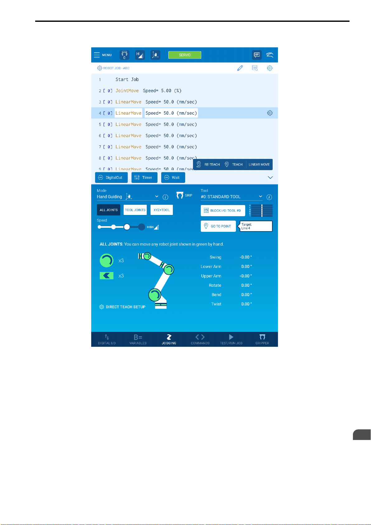
Confirm that the saved content was inserted into the job program on the Smart Pendant.
70
Page 71
5.1 Moving the Manipulator
HW2480573
71/144
11. Return to step 8 and repeat the steps until the series of manipulator movements is
completed.
This concludes the procedure.
Controlling the Manipulator
5
71
Page 72

5.1 Moving the Manipulator
HW2480573
72/144
72
Page 73

6
HW2480573
73/144
Mounting and Wiring the Hand
6.1 Required Items ..........................................................................................................74
6.2 Mounting the Hand...................................................................................................75
6.3 Connecting the Air Hoses ......................................................................................79
6.4 Connecting the I/O Cables ..................................................................................... 80
73
Page 74
6.1 Required Items
HW2480573
74/144
6.1 Required Items
This manual describes the required preparations and installation work for the manipulator based on the following
hand.
• Air gripper for collaborative robots manufactured by SMC (type: JMHZ2-16D-X7400B-DTP-N)
Name Quantity Remarks
Hand (air gripper) 1 –
Protective cover (valve side) 1 –
Protective cover (switch side) 1 –
Table 6.1 Hands and Hand Accessories
Hexagon socket head cap screw M4 (length:
10 mm)
Parallel pin (diameter: 6 mm, length: 10 mm) 1 For positioning the hand
Hexagon socket head cap screw M6 (length:
23 mm)
Polyurethane tube 1 Outside diameter: φ4, length: 2 m
Accessory cable 1 For connecting the hand to the manipulator
One-touch fitting (KQ2L04-M5A1) 2 –
One-touch fitting (KQ2L06-08A) 1 –
One-touch fitting (KQ2H04-06A) 1 –
4 For attaching protective covers
4 For mounting the hand
Table 6.2 Tools for Connecting the Air Hoses
Name Quantity Remarks
Union (for air inlet) 2 Air inlet on manipulator: M5 tapped hole
Union (for air outlet) 2 Air outlet on manipulator: outside diameter φ8
Air hose 4 –
Air supply equipment 1 –
Table 6.3 Tools for Connecting the I/O Cable
Name Quantity Remarks
General-purpose I/O terminal block 1 –
General-purpose I/O cable 1 –
I/O cable 1 –
Table 6.4 Tools
Name Quantity Remarks
Hex key (M4) 1 –
Hex key (M6) 1 –
Flat head screwdriver 1 For adjusting the fingers exhaust throttle valves
74
Page 75
6.2 Mounting the Hand
HW2480573
75/144
1. Jog the robot arm to a position that makes it easier to mount the hand.
Refer to the following section for details on jogging.
5.1.1 Jogging Each Axis on page 62
6.2 Mounting the Hand
2. Turn OFF the power supply to the robot controller and peripheral devices.
3. Confirm that the collaborative operation LED on the manipulator are not lit.
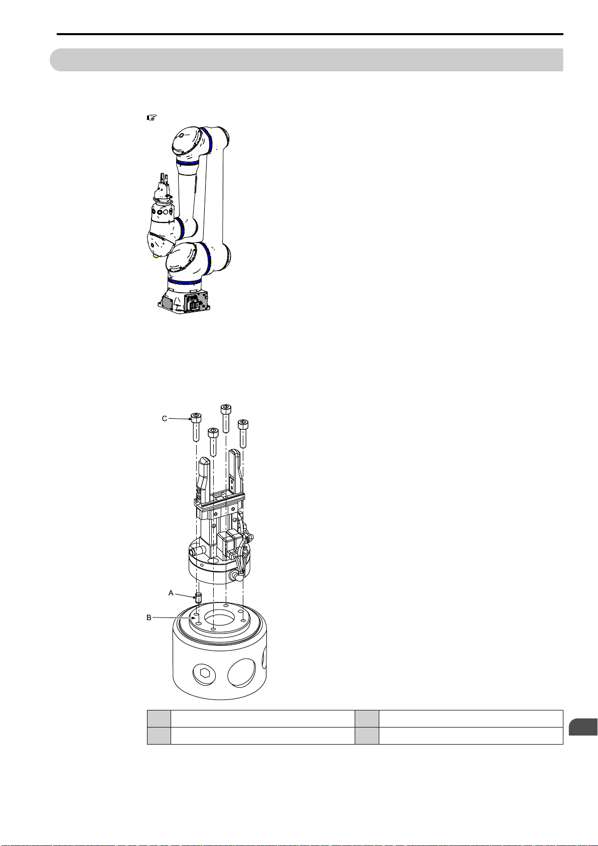
4. Insert the parallel pin into the flange surface of the T-axis of the manipulator.
Mount the hand aligned with the parallel pin to the manipulator and fix with the hexagon socket head
cap screws M6 (length: 23 mm). Tightening torque: 5.2 N∙m (0.53 kgf∙m)
A Parallel pin C Hexagon socket head cap screw M6 (length: 23 mm)
B Flange surface of the T-axis of the manipulator – –
Mounting and Wiring the Hand
6
75
Page 76
6.2 Mounting the Hand
HW2480573
76/144
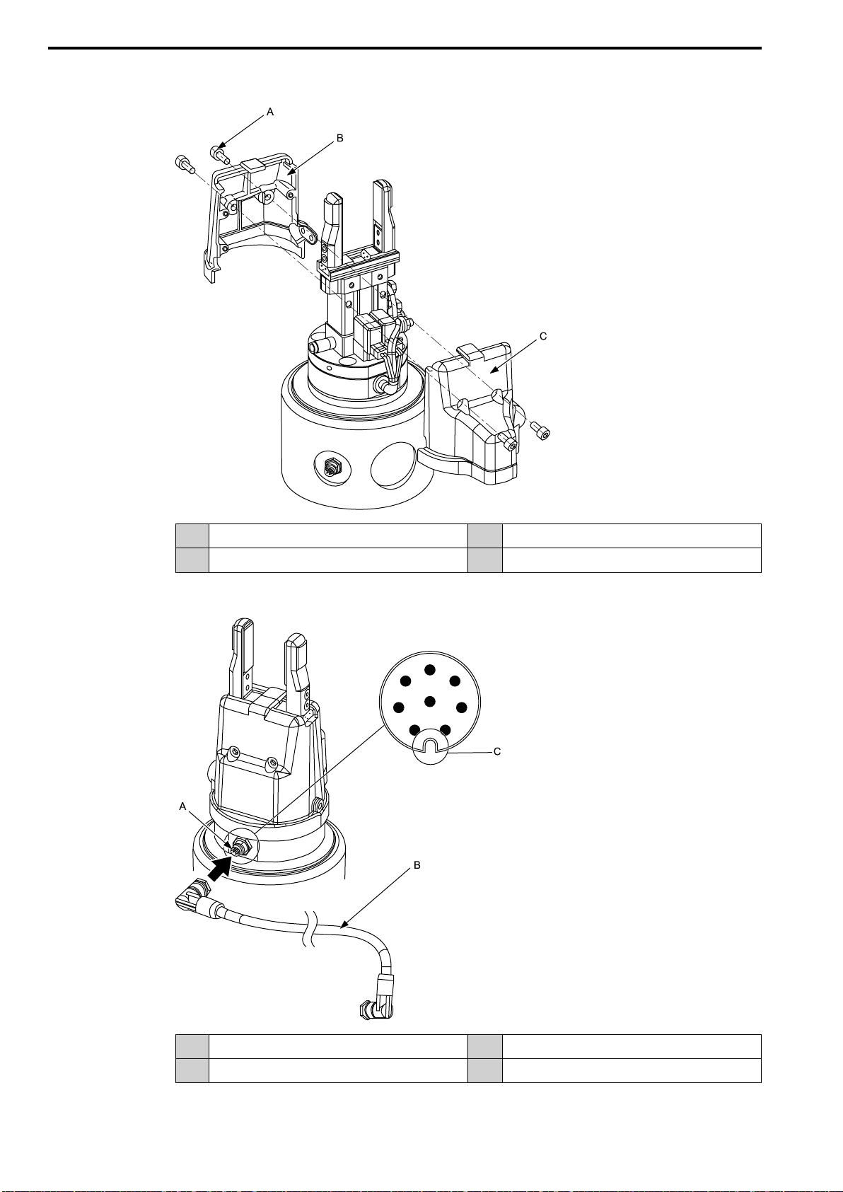
5. Attach the protective covers to the hand and fix with the hexagon socket head cap
screws M4 (length: 10 mm). Tightening torque: 1.0 N∙m (0.10 kgf∙m)
A Hexagon socket head cap screw M4 (length: 10 mm) C Protective cover (valve side)
B Protective cover (switch side) – –
6. Connect the cable to the hand. Connect the cable connectors by first checking that the
positioning key is aligned for both the hand-side and cable-side connectors.
76
A Connector for cable connection C Positioning key on hand-side connector
B Accessory cable – –
Page 77
6.2 Mounting the Hand
HW2480573
77/144
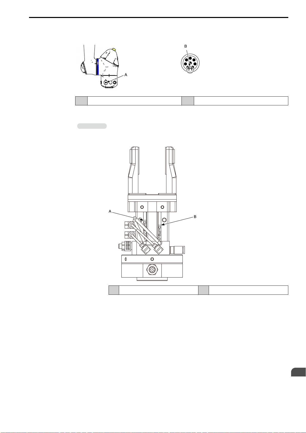
7. Connect the cable to the manipulator. Connect the cable to the I/O cable connector (S)
on the manipulator. Connect the cable connectors by first checking that the positioning
key is aligned for both the manipulator-side and cable-side connectors.
A I/O cable connector (S) B Positioning key
8. Connect the unions (included with the hand) to the air outlets on the T-axis flange of the
manipulator, and connect the air hoses.
Information
This note describes the adjustment method of the fingers opened/closed position.
The fingers section at the tip of the hand is set by default to respond at the opened limit and closed limit of
the fingers. The fingers opened/closed position can be adjusted by changing the position of the auto switches.
Fix the auto switches at the optimal positions for the shape of the workpiece.
A Fingers opened limit detection position B Fingers closed limit detection position
Mounting and Wiring the Hand
6
77
Page 78
6.2 Mounting the Hand
HW2480573
78/144
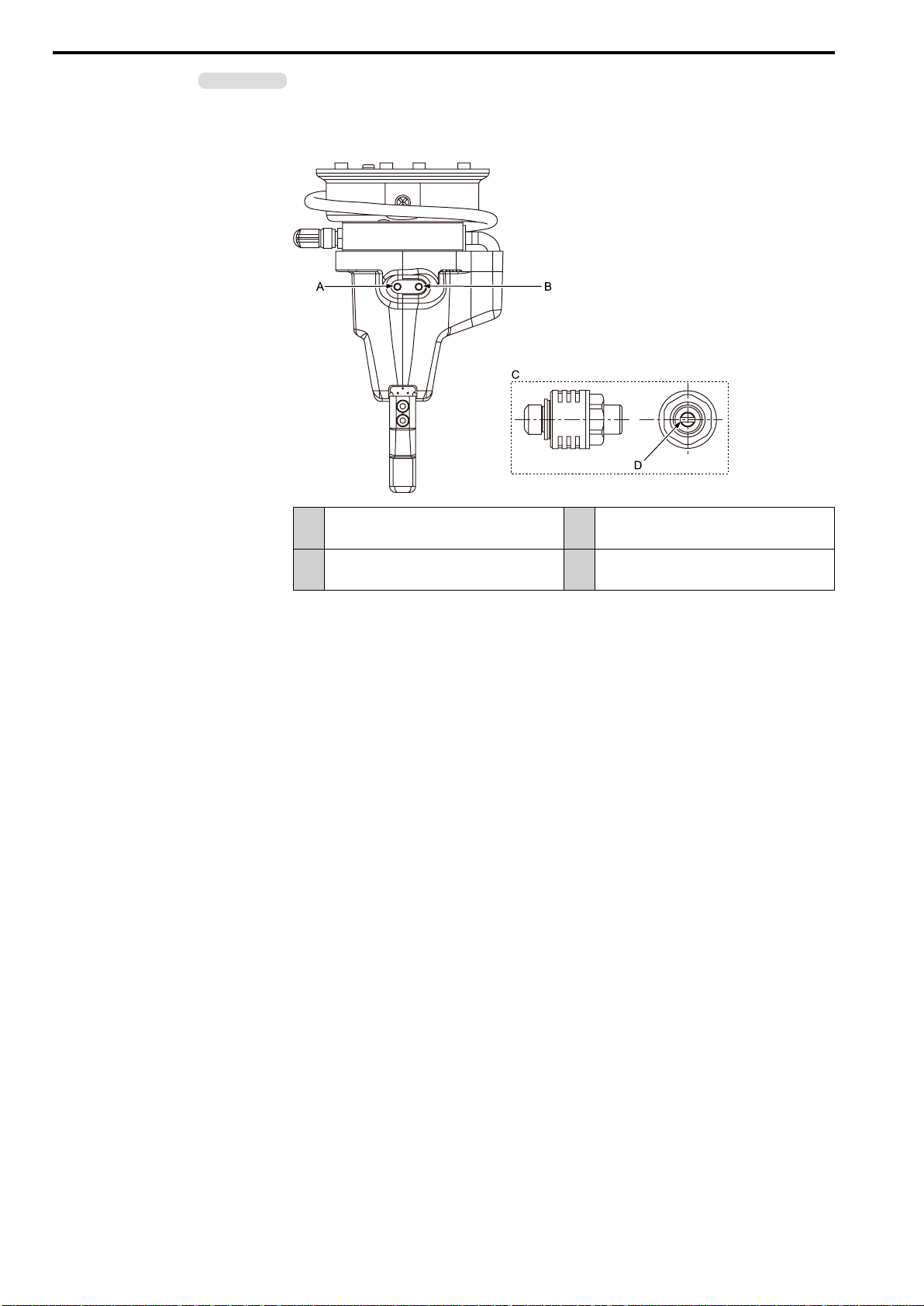
Information
This note describes the adjustment method of the fingers opening/closing speed.
Insert the flat head screwdriver into the throttle opening adjustment slot on the exhaust throttle valve and
adjust the throttle opening.
Adjust the throttle openings of both exhaust throttle valves to be the same amount. Operation may be unstable if the difference between the throttle openings is too great.
Exhaust throttle valve (for adjusting the open-
A
ing speed of the fingers)
C Enlarged view of the exhaust throttle valve
Exhaust throttle valve (for adjusting the clos-
B
ing speed of the fingers)
Throttle opening adjustment slot (use a flat
D
head screwdriver)
78
Page 79
6.3 Connecting the Air Hoses
HW2480573
79/144
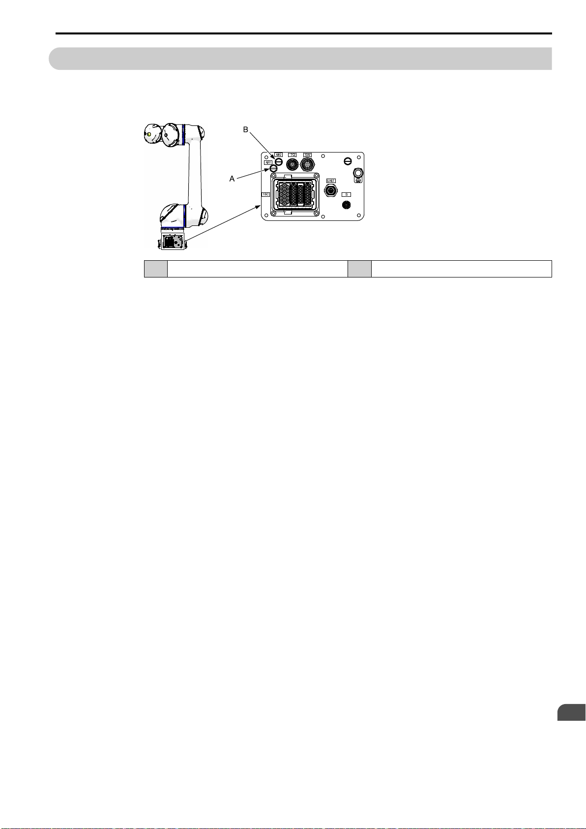
The customer must prepare the air supply source, unions, and air hoses for driving the air gripper.
1. Remove the plugs in the AIR1 and AIR2 inlets on the S-base part of the manipulator, and
then connect the unions.
A AIR1 inlet B AIR2 inlet
2. Connect the air hoses to the unions.
3. Connect the air hoses to the air supply equipment.
6.3 Connecting the Air Hoses
Mounting and Wiring the Hand
6
79
Page 80
6.4 Connecting the I/O Cables
HW2480573
80/144
6.4 Connecting the I/O Cables
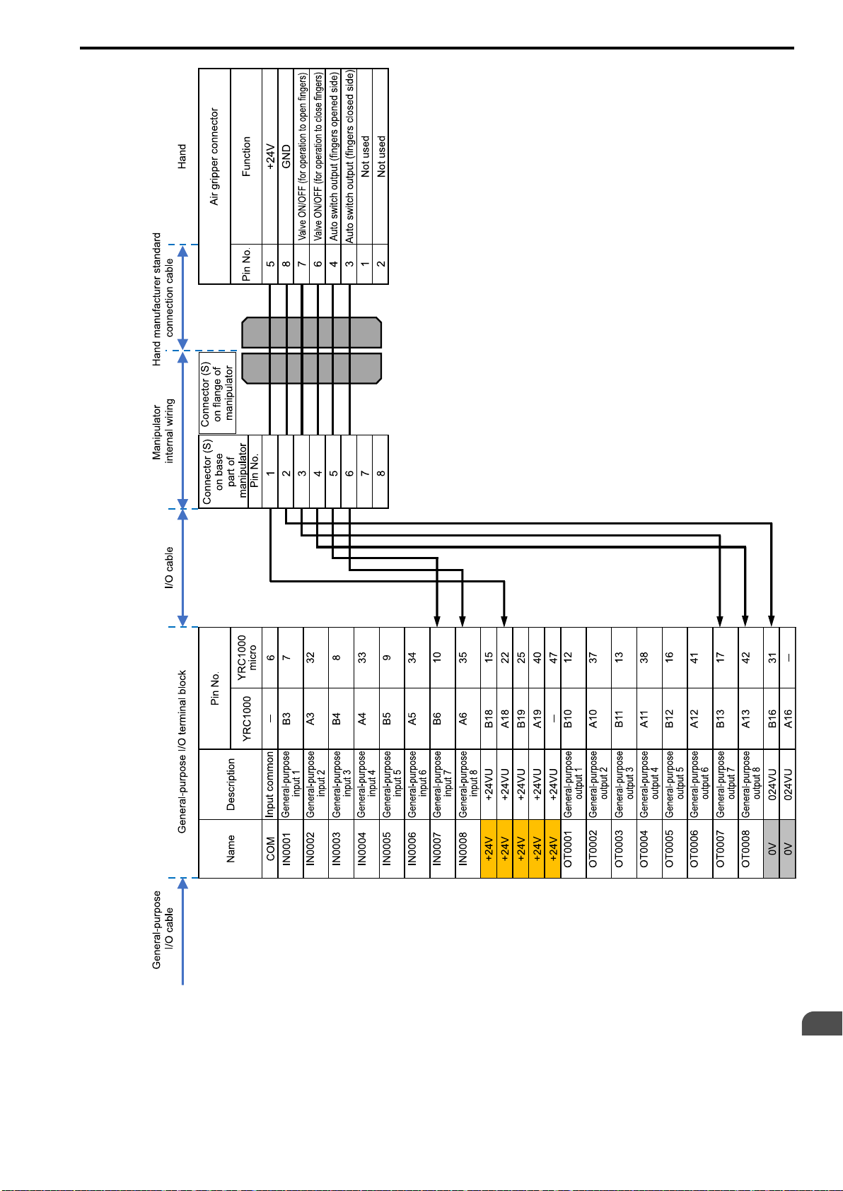
To perform the hand open/close fingers operation, the manipulator and robot controller must be connected
through the general-purpose I/O terminal block. Use the following connection example as a reference.
Note:
The connection example in this manual assumes the robot controller I/O is the NPN type (standard specification).
The customer must prepare the following connections:
Important
• Connecting the I/O cable to the general-purpose I/O terminal block
• Connecting the general-purpose I/O terminal block to the connector for the I/O cable on the S-base part of the manipulator
Information
Refer to the manual that is included with the end effector for the open/close fingers operation using simulated output for
I/O from the pendant.
80
Page 81
6.4 Connecting the I/O Cables
HW2480573
81/144
Mounting and Wiring the Hand
6
81
Page 82

6.4 Connecting the I/O Cables
HW2480573
82/144
82
Page 83

7
HW2480573
83/144
Settings
This chapter describes the configuration procedures for the settings of the collaborative robot.
7.1 Temporarily Disabling the Collaborative Operation Function ...................... 84
7.2 Configuring a Tool File............................................................................................91
7.3 Checking the Home Positions of the Torque Sensors and Setting the
Home Positions Again ............................................................................................ 98
7.3.1 Checking the Home Positions of the Torque Sensors ................................ 98
7.3.2 Setting the Home Positions of the Torque Sensors Again ......................... 99
7.4 Setting External Force Limits..............................................................................105
7.5 Configuring the Speed Limit Function..............................................................108
7.6 Enabling the Collaborative Operation Function............................................. 111
83
Page 84
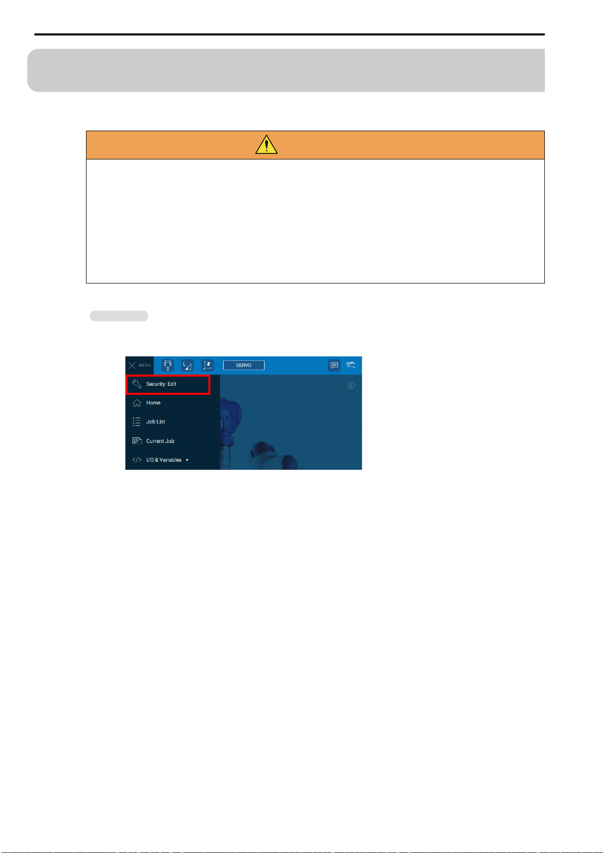
7.1 Temporarily Disabling the Collaborative Operation Function
HW2480573
84/144
7.1 Temporarily Disabling the Collaborative Operation
Function
The collaborative operation function must be disabled to temporarily disable external force monitoring and speed
limits by collaborative operation.
WARNING
There is a risk of injury to the operator when the PFL function is disabled. Perform this operation only after a thorough risk assessment has been conducted.
When collaborative operation is disabled, the stop function when contact is made by PFL
function and the escape from clamping function are also disabled. Always enable the collaborative operation function after the following settings are changed.
• Tool settings
• Torque sensor home position
• Speed limit
• External force limits
Use the following procedure to disable the collaborative operation function.
Information
Alarm 6003 "UNDEFINED SPEED LIMIT(PFL)" may be displayed during the procedure. The alarm can be reset by
tapping {RESET} on the alarm window.
1. From the status bar, select {MENU} - {Security: Edit}.
84
Page 85
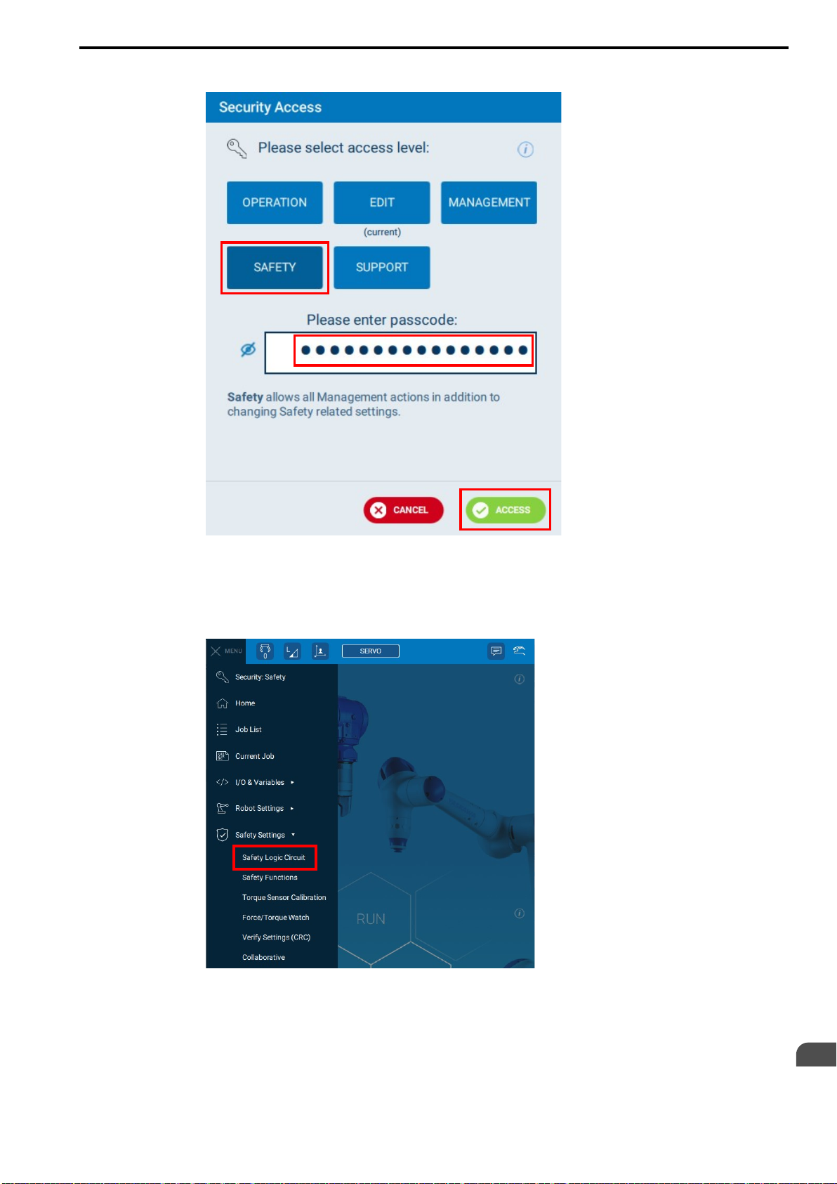
7.1 Temporarily Disabling the Collaborative Operation Function
HW2480573
85/144
2. On the Security Access window, select {SAFETY}.
3. Enter the password and select {ACCESS}.
Note:
The default password is set to "5555555555555555" (enter "5" 16 times).
4. Select {MENU} - {Safety Settings} - {Safety Logic Circuit}.
Settings
7
85
Page 86
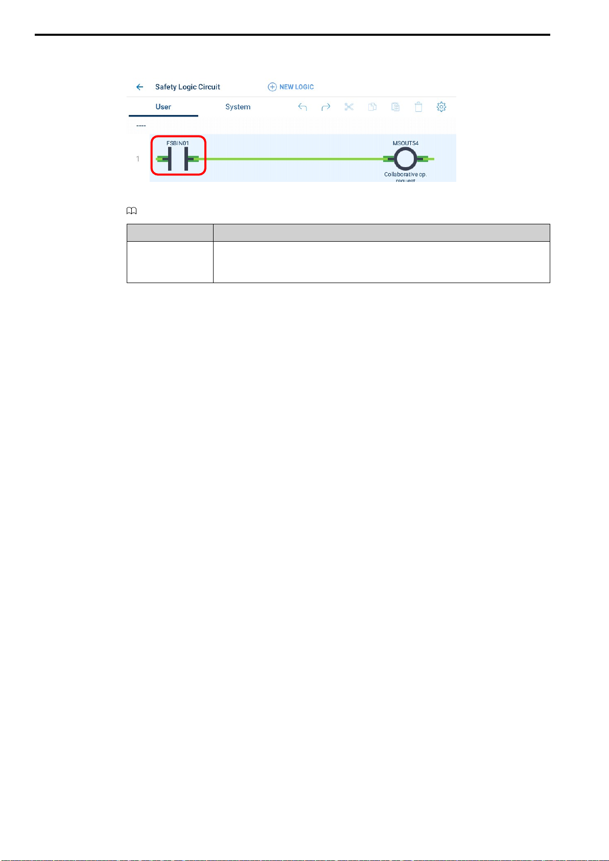
7.1 Temporarily Disabling the Collaborative Operation Function
HW2480573
86/144
5. Find the line on which the output (right side of the window) is set to "MSOUT54 (Collab-
orative op. request)". (Found on the first line of the user circuits in the default state.)
Refer to the following manual for details on the setting procedure for the safety logic circuit.
YRC1000/YRC1000micro Instructions For Smart Pendant (Manual. No.: HW1485509)
Signal Name Description
Enables and disables collaborative operation
MS-OUT54
• ON: Collaborative operation enabled
• OFF: Collaborative operation disabled
6. Tap the contact at the left edge of the relevant line (default state: FSBIN01).
The selected contact will be displayed as follows, and the Details pane will be displayed at the bottom
of the window.
86
Page 87
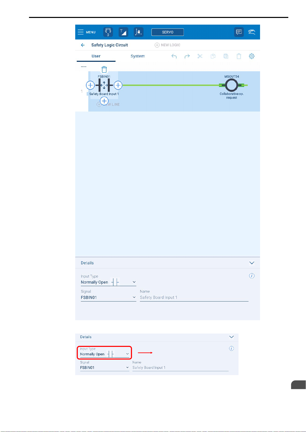
7.1 Temporarily Disabling the Collaborative Operation Function
HW2480573
87/144
7. Tap {Input Type}.
Settings
7
87
Page 88
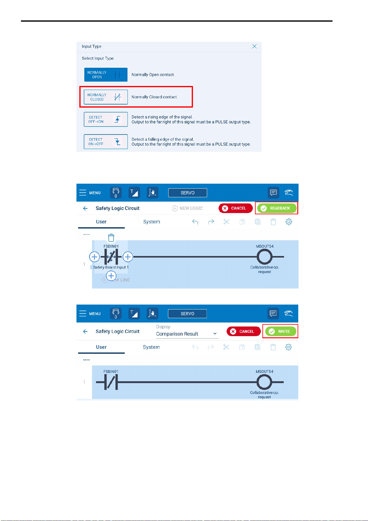
7.1 Temporarily Disabling the Collaborative Operation Function
HW2480573
88/144
8. Select {Normally Closed contact}.
9. Confirm that the MSOUT54 collaborative operation request signal is OFF.
10. Confirm that there are no mistakes in the safety logic circuit, and then tap
{READBACK}.
11. Tap {WRITE}.
88
Page 89
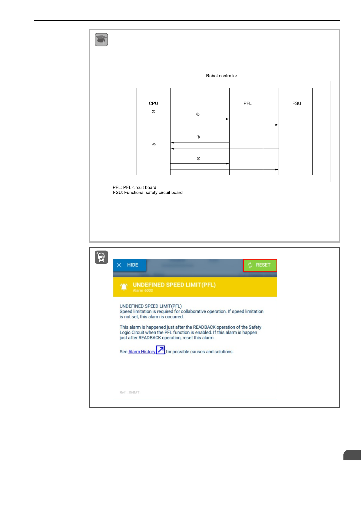
7.1 Temporarily Disabling the Collaborative Operation Function
HW2480573
89/144
Readback
Readback is the operation used to check if the data that was configured in the safety circuit board and PFL cir-
Term
cuit board is correct.
Data related to safety functions is redundantly stored in the memory on the safety circuit board and PFL circuit
board. The readback operation is required when data is changed on windows such as the safety function condition setting windows and tool windows.
Important
①: A setting value is changed with the pendant.
②: The setting value is transferred to the PFL and FSU.
③: Answer data is sent from the PFL and FSU to the CPU (readback).
④: The CPU value and answer data value are compared.
⑤: The setting value that was sent from the CPU is stored in the PFL and FSU.
Alarm 6003 "UNDEFINED SPEED LIMIT(PFL)" may be displayed. Tap {RESET} to reset the alarm.
Settings
7
89
Page 90
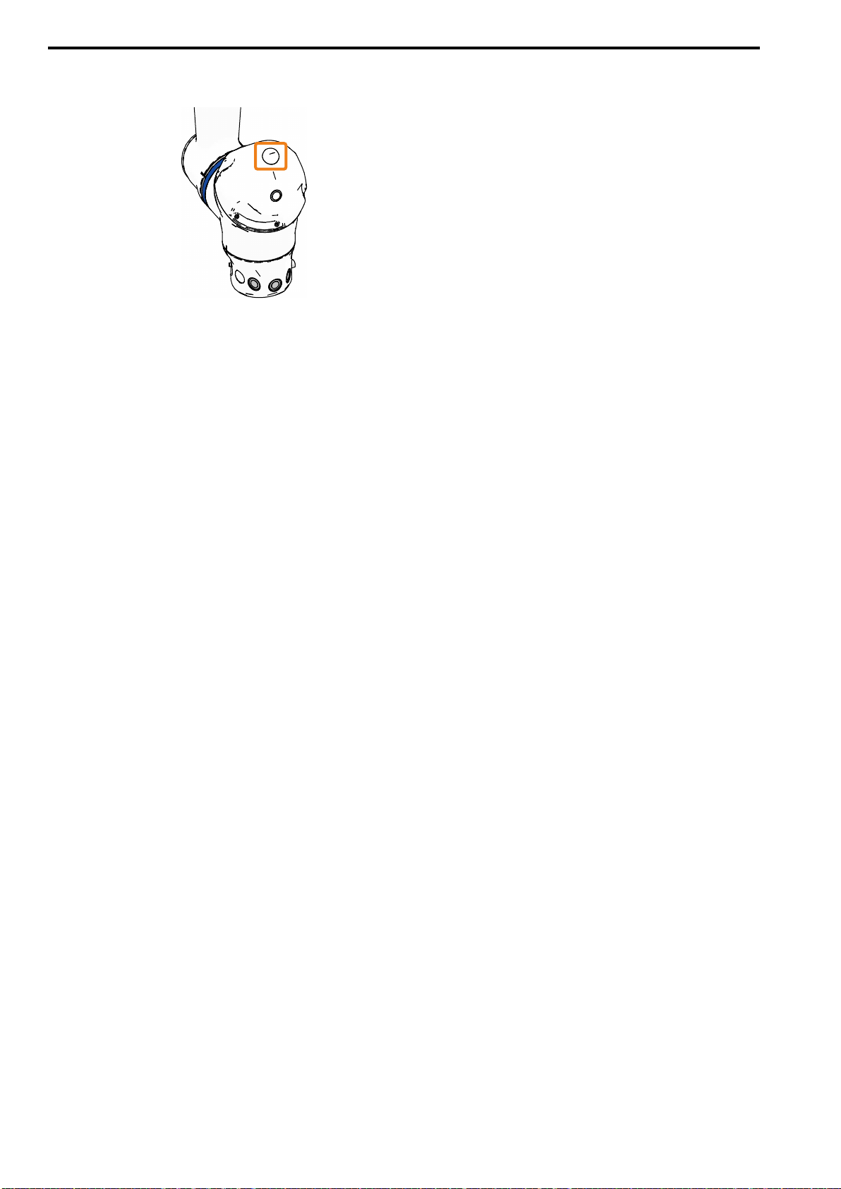
7.1 Temporarily Disabling the Collaborative Operation Function
HW2480573
90/144
12. MSOUT54 will be disabled, and the PFL function will be disabled. The collaborative
operation LED on the manipulator will go out.
This concludes the procedure.
90
Page 91
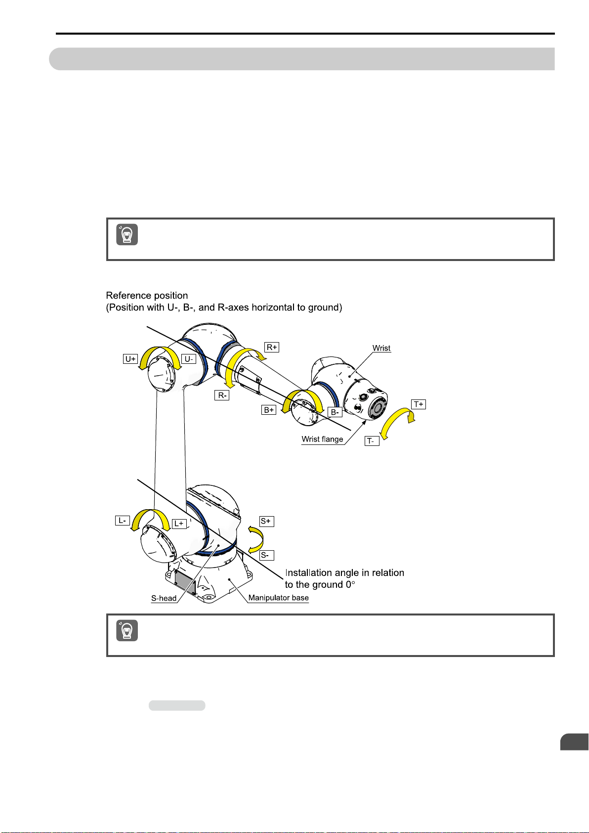
7.2 Configuring a Tool File
HW2480573
91/144
In collaborative operation mode, the external force is calculated by canceling the tool mass. For this reason, the
tool installed on the manipulator and the mass and position of the center of gravity of the workpiece to transport
must be configured in advance. The configured content is managed by selection number.
The tool selection number must also be changed at each step of the manipulator program in accordance with
changes in the status of the hand.
Example: When Grasping and Lifting a Workpiece on a Table with the Hand
• When the workpiece is not grasped, the tool mass is the mass of the hand only.
• When the workpiece is grasped and lifted, the tool mass is the mass of the hand and workpiece.
This section describes the configuration procedure that uses the automatic measurement for the tool load and the
center of gravity, which can be used to easily configure a tool file.
Automatic measurement for the tool load and the center of gravity can be used only when the manipulator is installed at an
installation angle in relation to the ground of 0°.
Important
To estimate the mass property of the tool load, move the manipulator to the home position (U-axis, B-axis, and
R-axis: level to the ground), and operate the U-axis, B-axis, and T-axis.
7.2 Configuring a Tool File
Use the following procedure to configure a tool file.
To correctly estimate the tool mass, position of the center of gravity, and moment of inertia, disconnect cables and wiring
that are connected to the tool so that no unnecessary loads are applied to the tool.
Important
1. Confirm that the workpiece is at hand.
Information
Prepare the workpiece in advance because it will be used in the rest of this procedure.
Settings
7
91
Page 92
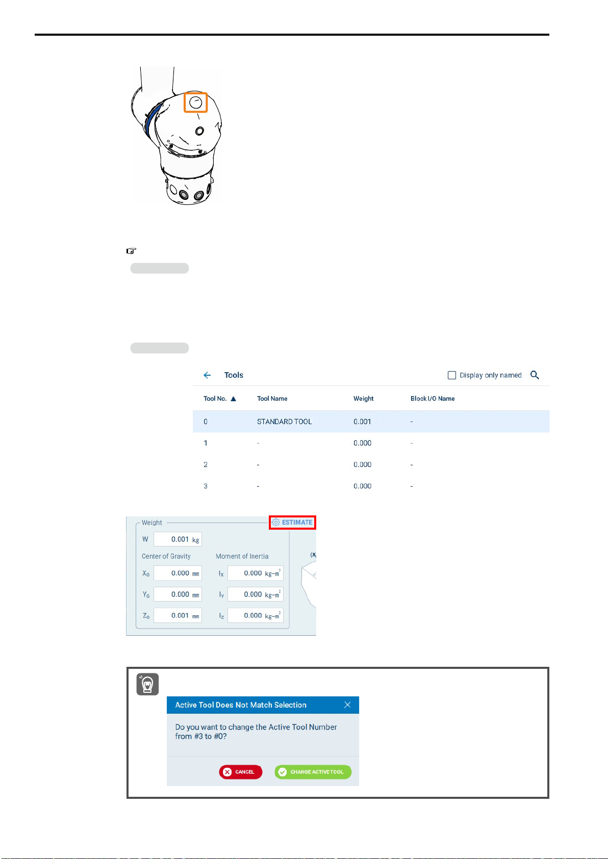
7.2 Configuring a Tool File
HW2480573
92/144
2. Confirm that the collaborative operation LED is not lit.
If the collaborative operation LED is lit, the collaborative operation function is enabled. Refer to the
following section for the operating procedure to disable the function.
7.1 Temporarily Disabling the Collaborative Operation Function on page 84
Information
3. Select {MENU} - {Robot Settings} - {Tools}.
4. Select tool number {0} with the cursor.
The Tool Detail Panel for tool number {0} will be displayed.
Information
Always disable the collaborative operation function before continuing with the rest of this procedure. The
subsequent operations may not correctly function if the collaborative operation function is enabled.
Data can be set in a maximum of 64 tool files. Information can be freely set in any tool file. Tool coordinates
number 0 is selected here to make the procedure easier to understand.
5. Tap {ESTIMATE} at the corner of the weight properties area on the Tool Detail Panel.
6. When the next message is displayed, tap {CHANGE ACTIVE TOOL}.
A dialog box will be displayed if the current tool differs from the tool that was selected in the list. These tools
must match to perform the tool load estimation.
Important
92
Page 93
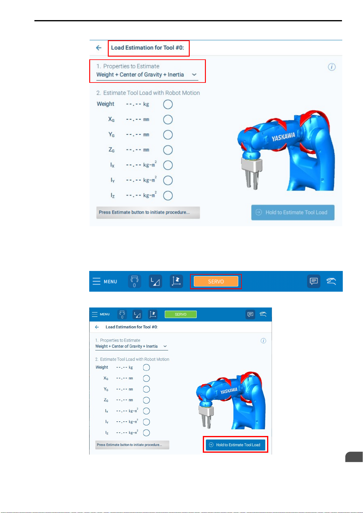
7.2 Configuring a Tool File
HW2480573
93/144
7. Tap {Properties to Estimate} and select {Weight + Center of Gravity + Inertia}.
8. Tap {SERVO}.
The background color will change to orange.
9. Squeeze the enable switch on the Smart Pendant.
{SERVO} will change to green and the servo ON state will be set.
10. Tap {Hold to Estimate Tool Load} to start estimating.
Settings
7
93
Page 94
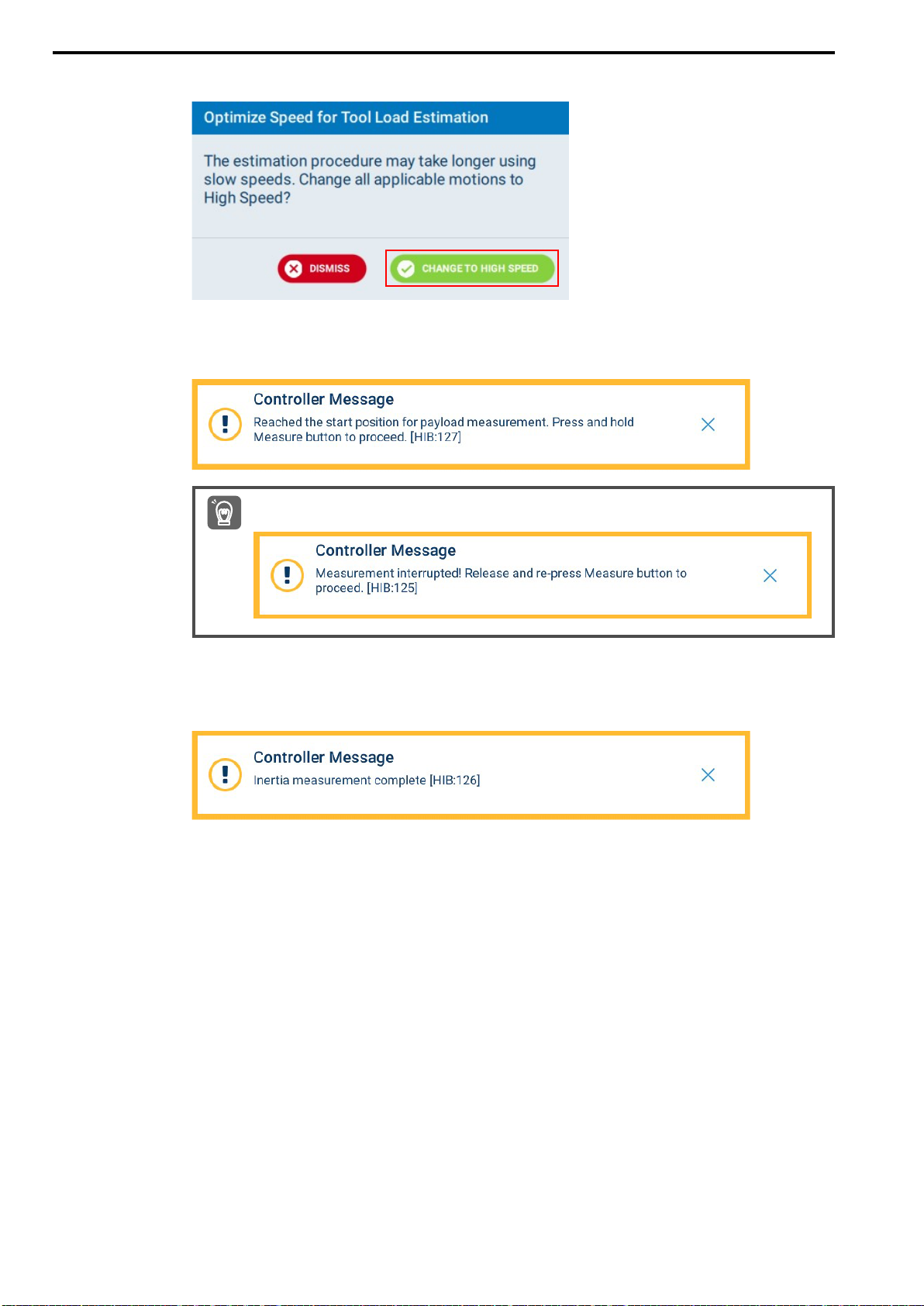
7.2 Configuring a Tool File
HW2480573
94/144
11. Select {CHANGE TO HIGH SPEED}.
12. The manipulator will move to the reference position. Press and hold {Hold to Estimate
Tool Load} until the following message is displayed.
The progress of automatic estimation will be displayed as a percentage.
The following message may be displayed if the finger that was tapping the menu was removed while the estimation operation was running. Tap {Hold to Estimate Tool Load} again.
Important
13. Repeat the tool load estimations according to the messages until the estimations of all
axes are completed.
14. When the following message is displayed, the tool load estimation for tool number 0 is
completed.
15. Remove the finger from the enable switch on the Smart Pendant.
94
Page 95
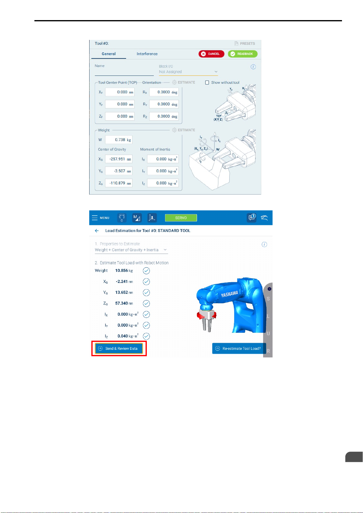
16. Confirm that the tool mass was set.
HW2480573
95/144
7.2 Configuring a Tool File
17. If there were no errors in the estimations, tap {Send & Review Data}.
Settings
7
95
Page 96
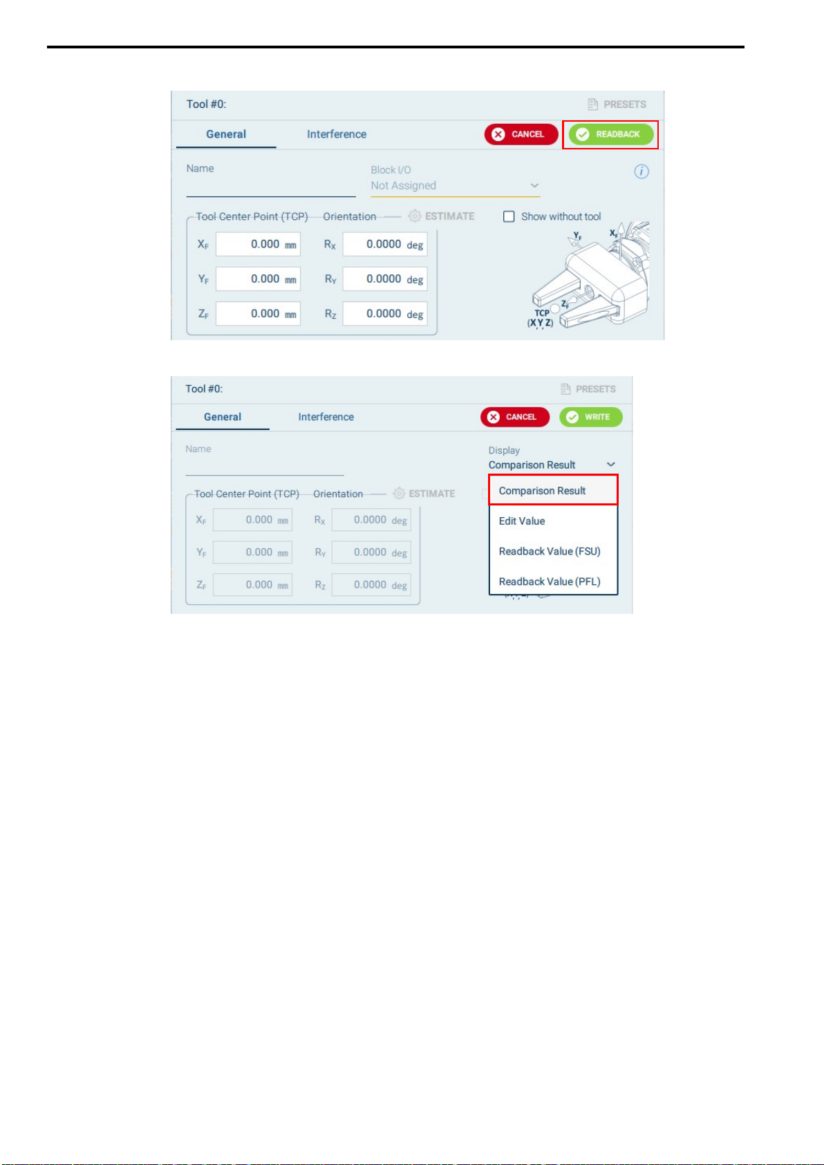
7.2 Configuring a Tool File
HW2480573
96/144
18. Tap {READBACK}.
19. Select {Comparison Result}.
20. Check the readback results.
Note:
If the data is the same between the robot controller CPU and circuit board, the configuration was correctly completed. If the data
is not the same, {Comparison Result} will display "***" instead of a value. In this case, what data was not updated on which circuit board must be checked.
21. Tap {WRITE}.
The measurement data will be registered in the tool file.
This concludes only the procedure to register the information for the hand in tool coordinates number
00.
Next, register the information for the hand and workpiece when the workpiece is grasped and lifted in
tool coordinates number 01.
Proceed to the next step.
22. Select tool number 1.
23. Set the hand to grasp the workpiece, and return to step 4 and repeat the configuration
procedure in this state.
Register the tool file with the hand grasping the workpiece in tool number 01.
The method to make the hand grasp the workpiece (method to open/close the hand) depends on the
type of hand. Refer to the manual for the hand for the detailed operating procedure.
24. When tool file configuration is completed, remove the workpiece from the hand.
This concludes the procedure.
96
Page 97
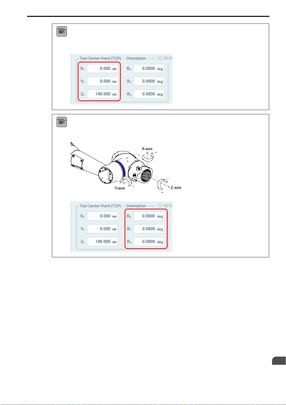
7.2 Configuring a Tool File
HW2480573
97/144
Tool Center Point (TCP)
The tool center point is the offset position from the wrist flange of the tool to the tip of the tool. For a simple tool, this is the
Term
offset in the X/Y/Z directions only. If necessary, a rotational offset can also be set.
When the tool center point is set, the manipulator can be operated in an orthogonal direction with the correct position set as
the center point. Positions can also be taught with the correct offset from the manipulator base.
Orientation of Tool Tip
The orientation of the tool tip is the amount of TCP rotation from the wrist flange of the tool. Tool rotation is entered in
Term
degrees.
Settings
7
97
Page 98
7.3 Checking the Home Positions of the Torque Sensors and Setting the Home Positions Again
HW2480573
98/144
7.3 Checking the Home Positions of the Torque Sensors
and Setting the Home Positions Again
The torque sensors built into the manipulator require regular inspections because deviations in the measured values will occur when the environment changes or the manipulator is mistakenly used, such as when the manipulator accidentally collides with something.
Information
Keeping a continuous record of the current torque values is recommended after the manipulator is installed. When the
user changes the system (e.g., changes the tool), move the manipulator to the same posture each time, and record the current values of {Joint Data} on the Force/Torque Watch window. The user can compare this recorded data to the current
values.
The following four conditions must be met when the allowable values and current values of torque are compared.
• The tool number matches the currently installed tool.
• The tool information is correct.
• When checking torque values, the values are recorded when the robot is set to the same posture (e.g., home position
posture) each time.
• The current values of {Joint Data} do not exceed the values listed below.
If the values of the axes are larger than the torque values listed in the following table, adjust the torque sensors.
If values exceed the values in the following table, the external force estimation will be greatly affected. For this reason,
adjusting the torque sensor for the relevant axis is highly recommended.
Axis S L U R B T
Torque Value 27.0 N·m 27.0 N·m 12.0 N·m 3.0 N·m 3.0 N·m 3.0 N·m
CAUTION
Even if the torque by external force is lower than the values given in the table above, adjust the
torque sensors when there is a problem with the operation of the PFL function or escape from
clamping function.
7.3.1 Checking the Home Positions of the Torque Sensors
To check the status of the torque sensors, regularly open the Force/Torque Watch window with the manipulator
set to the same posture and with the same load, record the torque values by external force of each axis, and check
if the difference between the values is growing larger from when the manipulator first started being used.
Use the following procedure to check the values.
1. Select {MENU} - {Safety Settings} - {Force/Torque Watch}.
98
Page 99
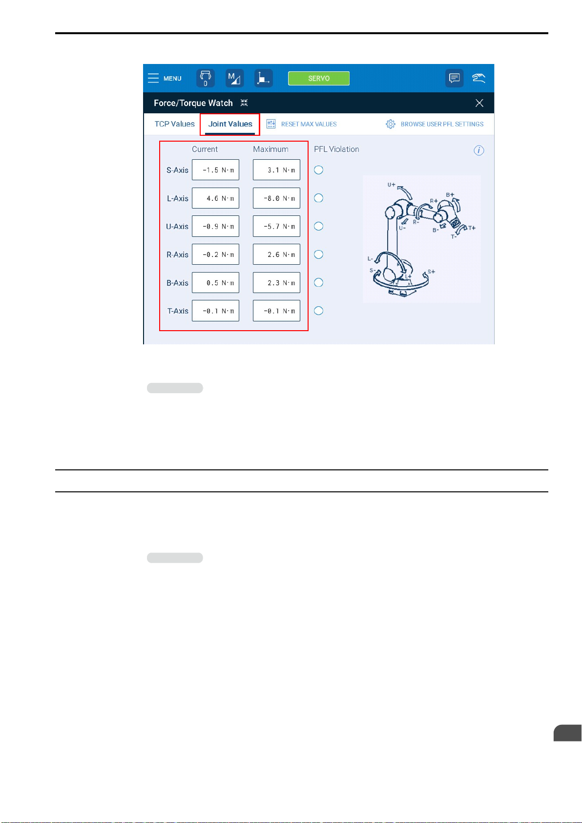
7.3 Checking the Home Positions of the Torque Sensors and Setting the Home Positions Again
HW2480573
99/144
2. Tap {Joint Values} and check the torque values by external force of each axis.
3. Compare the current values to the values when the manipulator first started being used
and check if the difference between the values is growing larger.
Information
This concludes the procedure.
If the values exceed the thresholds as a result of the comparison, adjust the torque sensors according to the following procedure.
Recording these values each day is recommended because these values must be checked regularly.
7.3.2 Setting the Home Positions of the Torque Sensors Again
If the home positions of the torque sensors are checked and the threshold values were exceeded, the home positions of the torque sensors must be set again. Use the following procedure.
1. Tap the tool icon and select tool #0.
Information
2. Select {MENU} - {Safety Settings} - {Torque Sensor Calibration}.
Select the tool file for the tool that is currently installed. In this example, number 0 is selected because the
tool file for the currently installed tool is set to tool number 0.
Settings
7
99
Page 100
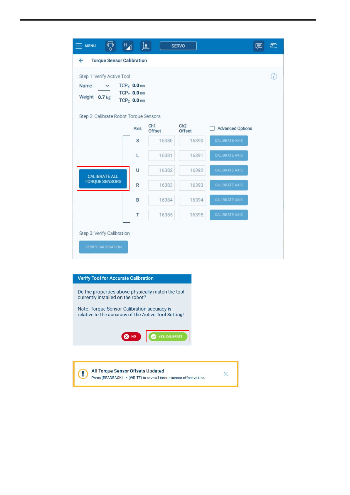
7.3 Checking the Home Positions of the Torque Sensors and Setting the Home Positions Again
HW2480573
100/144
3. Tap {CALIBRATE ALL TORQUE SENSORS}.
4. When the following message is displayed, select {YES, CALIBRATE}.
5. The following message will be displayed.
100
 Loading...