

Page 1
Electronic Lineshaft
With Alignment
F7 Drive Software
Technical Manual
Software Number: VSF11005X, Drive Models: CIMR-F7UXXXXXX-064, CIMR-F7UXXXXXX-065
Document Number: TM.F7SW.064, Date: 02/25/2010, Rev: 10-02
Page 2

This document is intended to provide proper installation and use of the Yaskawa drive with custom software. This
document is a supplement to the standard drive technical manual. It describes the effects on the drive parameters
and functions with the software installed. Read and understand this document and the standard drive technical
manuals before attempting to install, adjust, operate, inspect, or maintain the drive.
warnings in this document and the standard drive technical manuals.
Custom software is written to add
Observe all cautions and
functionality to a standard AC drive to enhance or enable use in a specific application. The software is loaded to
the flash ROM area of the control board, and replaces the standard drive software. Custom software can add new
functions, modify standard functions, or even inhibit standard functions. It can be used to modify display text or
parameter names. Custom software is usually loaded to the drive before delivery. The control board and drive
nameplate are assigned unique part numbers and the software is registered, archived, and retrievable.
When seeking support for a drive with custom software, it is imperative to provide the unique part number shown
on the drive nameplate. The software has been flashed to the control board memory and the operation of
parameters, functions, and monitors are different than the standard drive software, as described herein.
1.0 Overview
The Electronic Lineshaft (ELS) function allows a drive to precisely follow a master encoder (PG) signal in
speed, direction, and phase. The follower can match its position (phase angle) to the master within several
quadrature encoder counts. The function is used in applications where the machinery being driven requires
two mechanically isolated, moving parts to maintain a constant position relationship. The gear ratio between
the master and the follower is infinitely adjustable. In addition, a gear ratio adjustment (“draw”) can be added
to the speed reference via parameter, analog input, multi-function input, MOP, or network communication.
The drive can also be run in a pure speed follower mode for applications that do not require matched position,
only velocity following.
Both the master and follower encoder signals are fed into the follower drive’s dual encoder (PG) option card.
The master encoder speed is multiplied by the programmed gear ratio to determine the speed reference. The
error between the master and follower position is determined. This is fed into a PI controller, which is in turn
added to the previously calculated speed reference. When the drive is configured as a speed follower, the
position regulator is disabled.
A signed-run mode is also available in ELS. When P1-01 = 5 (Electronic Line Shaft - Sign Run), ELS
functions identically to standard ELS (P1-01 = 4), with the following difference:
When a reverse run command is given through the terminal S2 digital input, the follower will match the
When a forward run command is present through terminal S1, the follower will run in the same direction is
With revision VSF110052, the software adds an automatic alignment feature to the base electronic line shaft
software. This is accomplished by using two proximity switches connected to the trigger inputs on the follower
drive. One switch is used to indicate the position of the master, and the other switch is used to indicate the
position of the follower. When the alignment feature is activated and the machine is running, the distance
between the trigger switches is measured and then compensated for by either advancing or retarding the
follower motor.
velocity and phase of the master, but in the opposite direction. If the master runs in the forward direction,
the follower will run in reverse direction. If the master runs in the reverse direction, the follower will run in
the forward direction.
the master.
Date: 02/25/2010, Rev: 10-02 Page 2 of 34 TM.F7SW.064
Page 3
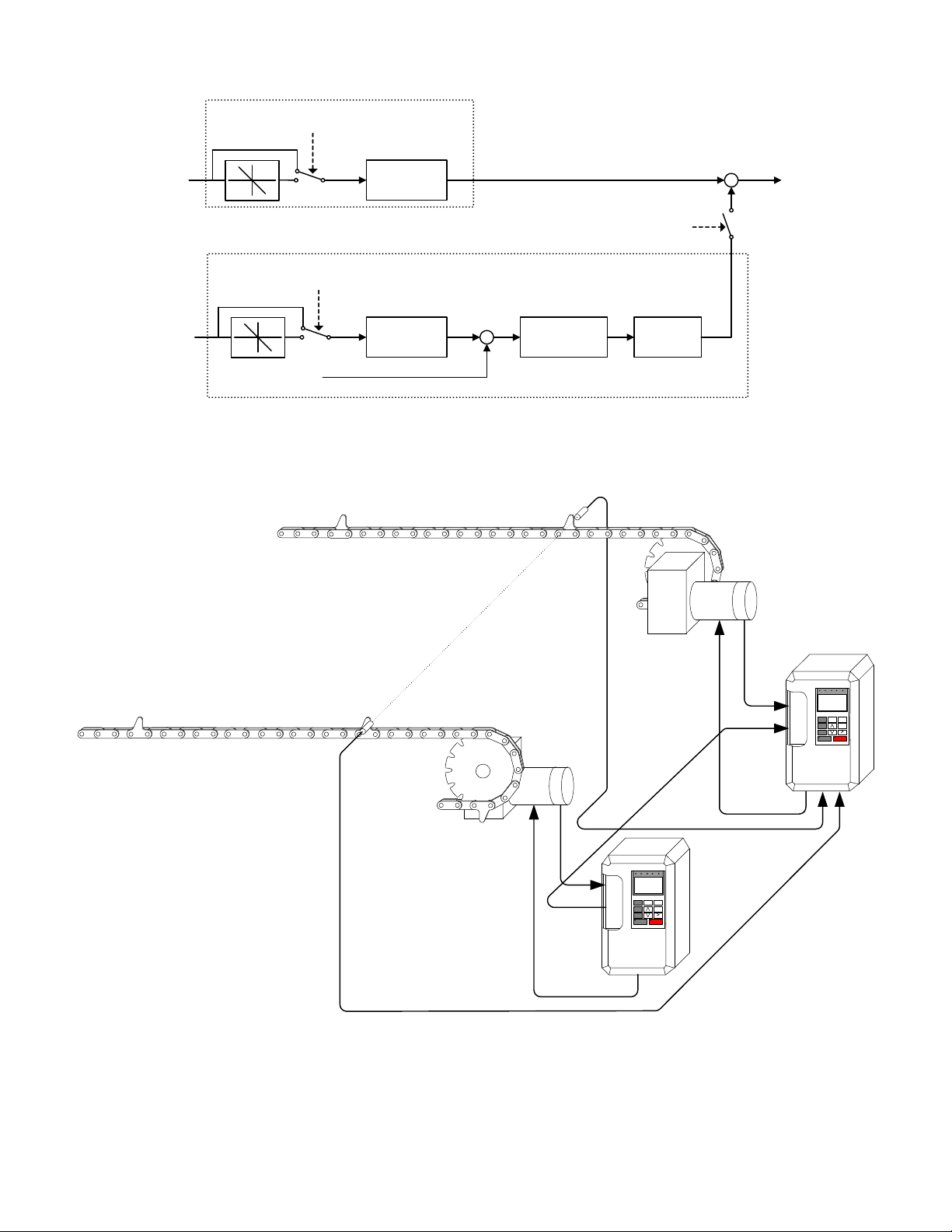
Speed Calculation
ELS – Sign Mode Enabled
AND Reverse Run Command
Master Encoder
Master Encoder
Pulse Count
Speed
Position Regulator
ELS – Sign Mode Enabled
AND Reverse Run Command
Follower Encoder
Pulse Count
Gear
Calculation
Gear
Calculation
ELS Mode Enabled OR
ELS – Sign Mode
Enabled
+
-
Position Error
Accumulator
PI
Controller
+
+
Simplified Block Diagram of the Electronic Lineshaft Function
Gear
Follower
Box
d
e
n
g
i
l
A
Master
Motor
Master Motor
Master Encoder
Master Trigger Switch
Follower Trigger Switch
PG-X2
Motor
Follower Motor
Follower Encoder
F 7
Simplified Application Example of Electronic Lineshaft with Alignment Function
Frequency
Reference
PG-W2
F 7
Date: 02/25/2010, Rev: 10-02 Page 3 of 34 TM.F7SW.064
Page 4
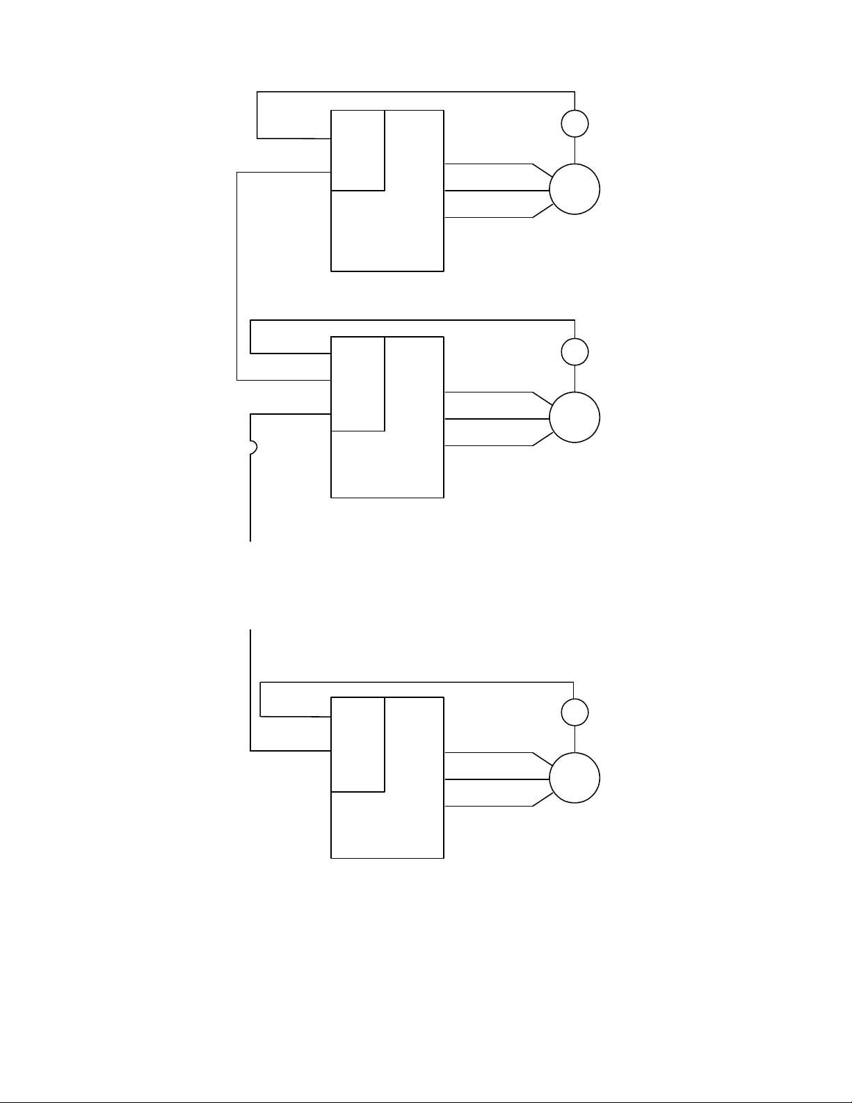
Input Channel
Monitor Output
Channel 1 Input
Channel 2 Input
Monitor Output
.
.
.
Channel 1 Input
Channel 2 Input
PG-X2
Pulse
Master Drive
PG-W2
Pulse
Follower Drive 1
PG-W2
Follower Drive n
F7
F7
.
.
.
F7
PG
M
PG
M
PG
M
Typical Connection Diagram for Electronic Lineshaft
Date: 02/25/2010, Rev: 10-02 Page 4 of 34 TM.F7SW.064
Page 5
2.0 Changes from Standard Product
a. The Motor 2 Selection (H1-0X = 16) multi-function digital input function is deleted (only Motor 1 can be
used).
b. The kWh monitors (U1-29 and U1-30) are deleted.
c. Parameter E2-04 (Motor Poles) is available in all control modes (Advanced access level only for V/f and
Open Loop Vector).
d. T he follower drive uses acceleration and deceleration times of zero during standard Electronic Line Shaft
(P1-01 = 4, 5).
e. All “A2” parameters along with the entire user access level have been deleted from this software.
3.0 Limitations
a. For ELS modes (P1-01 = 4, 5), Flux Vector control mode is highly recommended (A1-02 = 3).
b. For ELS modes (P1-01 = 4, 5), the gear ratio must be exactly expressed, including remainder, to prevent
phase drift (error). See section 5.0.
c. The proper encoder (PG) option card must be used based on the control mode and follower mode
selection. The table below shows the supported option cards for each configuration.
d. If the “Clear Position Error” digital input is activated when an alignment is being performed, the drive could
possibly experience a step-change in frequency reference.
e. Alignment accuracy will be lessened at higher speeds. This is due to latency in the trigger
switches themselves and the drive’s digital inputs and internal scan rate.
Encoder (PG) Option Card Selection
Control Mode P1-01 = 1, 2, 3 (Speed Follower) P1-01 = 4, 5 (ELS)
V/f w/ PG PG-W2, PG-Y2, PG-Z2
Open Loop Vector PG-B2, PG-T2, PG-X2, PG-W2, PG-Y2, PG-Z2
Flux Vector PG-W2, PG-Y2, PG-Z2
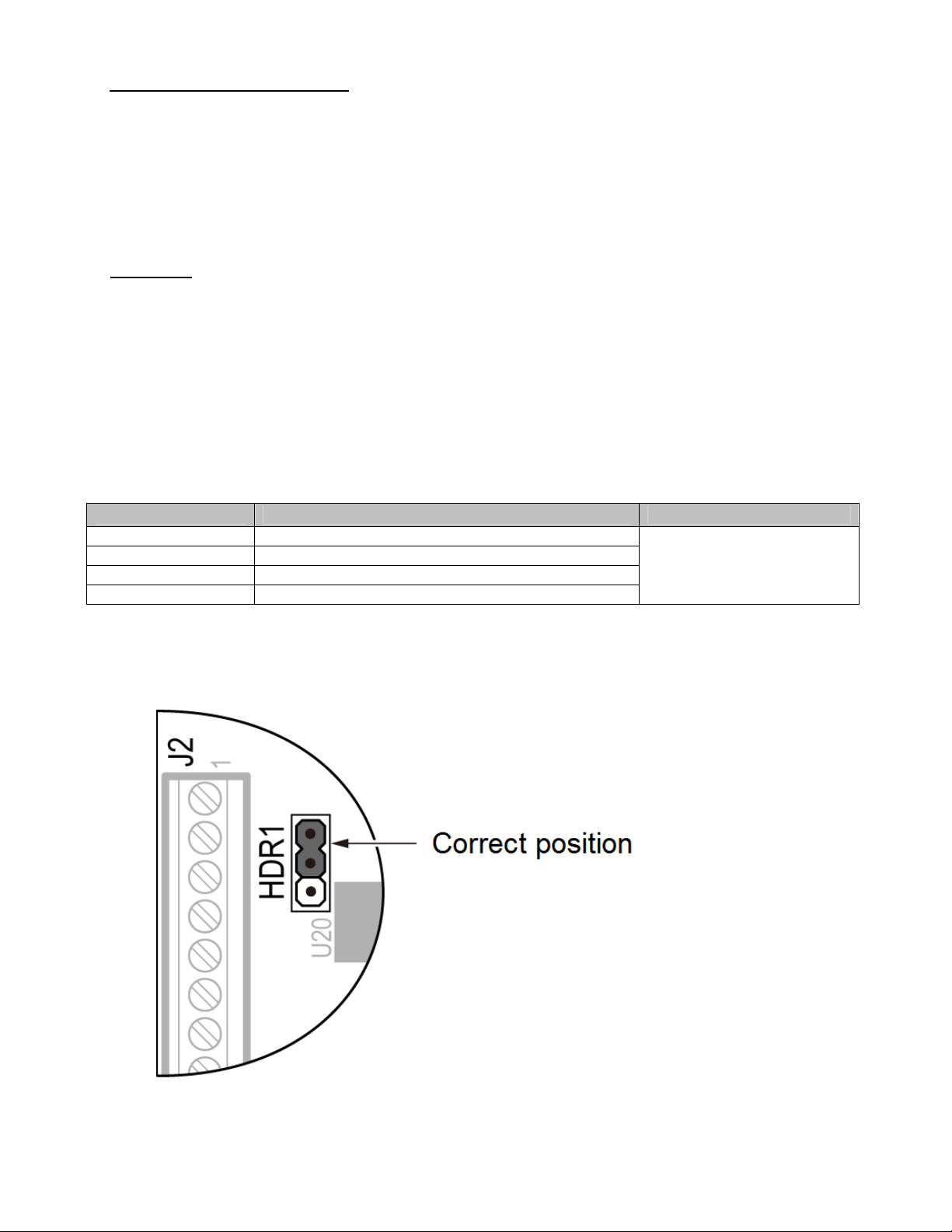
V/f PG-B2, PG-T2, PG-X2, PG-W2, PG-Y2, PG-Z2
PG-W2, PG-Y2, PG-Z2
Note: If the PG-W2 option is used, jumper HDR1 must be set to the correct position
according to the figure below.
Date: 02/25/2010, Rev: 10-02 Page 5 of 34 TM.F7SW.064
Page 6
4.0 Related Parameters and Functions
4.1 Parameters
Parameter
Address
Number
Modbus
Parameter Name
Digital Operator
Range
Description
Display
Selects the follower mode.
0: Disabled
Follower mode is disabled
and the follower drive runs
from the normal frequency
reference (B1-01).
1: Speed – Both Dir
The follower drive follows
the master encoder speed
in both directions.
2: Speed – One Dir
The follower drive follows
the master encoder speed
in the direction of the run
command only.
3: Speed – Abs Val
The follower drive follows
the master encoder speed
but ignores the master
P1-01 600H
Follower Mode
Selection
Follower Mode
encoder direction (motion is
always in the direction of
the run command).
4: Elec Line Shaft
0 ~ 5 0 No Q Q Q Q
The follower drive follows
the master encoder speed
and position (both
directions). Terminals S1 or
S2 can be used to issue the
run command. There is no
directional effect.
5: ELS – Sign Run
The follower drive follows
the master encoder speed
and position (both
directions). When a forward
run command is present
(terminal S1), the drive
follows the master in the
same direction. When a
reverse run command is
present (terminal S2), the
drive follows in the opposite
direction of the master.
*1: Access Level (A1-01): Q = “Quick Start”, A = “Advanced”, F = “Factory”.
Default
Change During
Run
Control Mode *1
Open Loop
V/f w/ PG
V/f
Vector
Flux Vector
Date: 02/25/2010, Rev: 10-02 Page 6 of 34 TM.F7SW.064
Page 7

4.1 Parameters (continued)
Parameter
Address
Number
Modbus
Parameter Name
Digital Operator
Display
Description
Range
Default
Change During
Run
Control Mode *1
Open Loop
V/f w/ PG
V/f
Vector
Flux Vector
P1-02 601H
P1-03 602H
Master Encoder
PPR
Master PG PPR
Ratio Numerator
(Upper 4 Digits)
Ratio Num High
Sets the pulses per revolution
(PPR) of the master encoder
(PG).
Sets the upper 4 digits of the
primary gear ratio numerator.
See section 5.1.
20 ~
60,000
Pulses
0 ~
9999
Ratio
P1-04 603H
Denominator
(Upper 4 Digits)
Sets the upper 4 digits of the
primary gear ratio
denominator. See section 5.1.
0 ~
9999
Ratio Den High
P1-05 604H
Ratio Numerator
(Lower 4 Digits)
Ratio Num Low
Sets the lower 4 digits of the
primary gear ratio numerator.
See section 5.1.
0 ~
9999
Ratio
Sets the lower 4 digits of the
primary gear ratio
denominator. See section 5.1.
0 ~
9999
P1-06 605H
Denominator
(Lower 4 Digits)
Ratio Den Low
Sets the numerator of the
secondary gear ratio. Active
when a multi-function digital
input is set to 81 (Ratio 2
Select) and the input is closed.
Sets the denominator of the
secondary gear ratio. Active
when a multi-function digital
input is set to 81 (Ratio 2
Select) and the input is closed.
1 ~
65,535
1 ~
65,535
P1-07 606H
P1-08 607H
Ratio 2
Numerator
Ratio 2 Num
Ratio 2
Denominator
Ratio 2 Den
Sets when the position error
accumulator is enabled in the
follower drive.
0: Only During Run
Position error is only
calculated when the
follower drive is running
during High Slip Braking)
1: Always
Position error is calculated
0 ~ 1 0 No A A A A
(not
.
P1-09 608H
Position Error
Accumulation
Selection
Pos Accum
Select
whenever power is applied
to the follower drive.
Note: ELS modes only.
*1: Access Level (A1-01): Q = “Quick Start”, A = “Advanced”, F = “Factory”.
1024 No Q Q Q Q
1000 Yes Q Q Q Q
1000 Yes Q Q Q Q
0 Yes A A A A
0 Yes A A A A
1 Yes A A A A
1 Yes A A A A
Date: 02/25/2010, Rev: 10-02 Page 7 of 34 TM.F7SW.064
Page 8
4.1 Parameters (continued)
Parameter
Address
Number
Modbus
Parameter Name
Digital Operator
Range
Description
Display
Selects the units used for the
follower drive Position Error
Monitor (U1-96).
0: Encoder Counts
Position error is displayed in
quadrature follower encoder
counts (cts).
1: Motor Revs
P1-10 609H
Position Units
Selection
Position Units
Position error is displayed in
follower motor revolutions
(0.001rev).
2: Motor Degrees
0 ~ 3 0 Yes A A A A
Position error is displayed in
follower motor degrees
(0.1°).
3: Motor Radians
Position error is displayed in
follower motor radians
(0.001rad).
Note: ELS modes only.
Sets the digital gear ratio
adjustment of the follower
drive. The gear ratio
adjustment is also influenced
by the analog, MOP and
communication gear ratio
-99.99
~
+99.99
%
P2-01 60AH
Digital Ratio
Adjustment
Digital RatioAdj
adjustments.
Sets the time for the MOP ratio
P2-02 60BH
MOP Adjust Time
MOP Adjust
Time
adjustment to change by
100.00% when the MOP
Adjust Increase or MOP Adjust
Decrease multi-function input
0.0 ~
6000.0
sec
is closed.
P2-03 60CH
Gear Ratio
Adjustment Ramp
Time
Ratio Adj Ramp
Sets the time for the composite
gear ratio adjustment of the
follower drive to change by
100.00%.
0.0 ~
6000.0
sec
*1: Access Level (A1-01): Q = “Quick Start”, A = “Advanced”, F = “Factory”.
Change During
Control Mode *1
Default
Run
V/f
V/f w/ PG
Open Loop
Flux Vector
Vector
0.00 Yes A A A A
50.0 Yes A A A A
10.0 Yes A A A A
Date: 02/25/2010, Rev: 10-02 Page 8 of 34 TM.F7SW.064
Page 9
4.1 Parameters (continued)
Parameter
Address
Number
Modbus
Parameter Name
Digital Operator
Range
Description
Display
Selects the advance/retard
functionality of the follower
drive.
0: Continuous
The follower will advance or
retard continuously while
the Advance Follower or
Retard Follower multifunction input is closed. P205 sets amount of
advance/retard encoder
counts per second.
1: Step
0 ~ 1 0 No A A A A
P2-04 60DH
Advance/Retard
Mode Selection
Adv/Ret Mode
Sel
The follower will advance or
retard by the amount set in
parameter P2-05 each time
the Advance Follower or
Retard Follower multifunction input is closed.
Note: ELS modes only.
Sets the number of quadrature
follower encoder counts the
follower will advance/retard per
second when P2-04 = 0. Sets
the step amount of the
advance/retard function when
P2-04 = 1.
0 ~
65,535
Counts
P2-05 60EH
Advance/Retard
Amount
Adv/Ret Amount
Note: ELS modes only.
Sets the amount of position
error in quadrature follower
encoder counts that will
P2-06 60FH
Follower
Deviation Level
Follower Dev Lvl
activate the follower deviation
detection. Also sets the
scaling for the Position Error
analog output selection (H3-
0 ~
65,535
Counts
05, H3-09 = 94).
Note: ELS modes only.
*1: Access Level (A1-01): Q = “Quick Start”, A = “Advanced”, F = “Factory”.
Change During
Control Mode *1
Default
Run
V/f
V/f w/ PG
Open Loop
Flux Vector
Vector
2048 Yes A A A A
4096 No A A A A
Date: 02/25/2010, Rev: 10-02 Page 9 of 34 TM.F7SW.064
Page 10

4.1 Parameters (continued)
Parameter
Address
Number
Modbus
Parameter Name
Digital Operator
Range
Description
Display
Selects the follower drive
action when the position error
exceeds the P2-06 setting.
0: No Detection
P2-07 610H
Follower
Deviation
Selection
Follower Dev Sel
The drive continues to run.
1: Alarm
The drive continues to run
and an FDEV alarm flashes
on the digital operator.
0 ~ 2 2 No A A A A
2: Fault (Coast to Stop)
The FDEV fault is
displayed, the drive fault
contact is activated, and the
motor coasts to a stop.
Selects which input encoder
signal is sent to the PG
monitor output when using a
P2-08 611H
Encoder (PG)
Monitor Channel
Selection
PG Mon Ch
Select
dual channel PG option card
(PG-W2, PG-Y2, or PG-Z2).
0: Channel 1
Encoder 1 is sent to the
monitor output.
0 ~ 1 1 Yes A A A A
1: Channel 2
Encoder 2 is sent to the
monitor output.
Determines if the MOP gear
adjustment is memorized when
P2-09 612H
MOP Adjustment
Memorization at
Power Off
MOP Mem @Pwr
Off
the drive loses power.
0: Disabled
MOP adjustment is not
memorized at power down.
1: Enabled
0 ~ 1 0 No A A A A
MOP adjustment is
memorized at power down.
Sets the proportional gain of
the position regulator PI loop.
Note: ELS modes only.
Sets the integral time of the
position regulator PI loop.
Note: ELS modes only.
0.00 ~
100.00
0.00 ~
50.00
sec
P3-01 614H
P3-02 615H
Position P Gain
Position P Gain
Position I Time
Position I Time
*1: Access Level (A1-01): Q = “Quick Start”, A = “Advanced”, F = “Factory”.
Change During
Control Mode *1
Default
Run
V/f
V/f w/ PG
Open Loop
Flux Vector
Vector
5.00 Yes A A A A
0.00 Yes A A A A
Date: 02/25/2010, Rev: 10-02 Page 10 of 34 TM.F7SW.064
Page 11

4.1 Parameters (continued)
Parameter
Address
Number
Modbus
Parameter Name
Digital Operator
Display
Description
Range
Default
Change During
Run
Control Mode *1
Open Loop
V/f w/ PG
V/f
Vector
Flux Vector
P3-03 616H
Position
Regulator Filter
Time
Pos Filter Time
Sets the filter time of the
position regulator output. This
is a first order lag filter.
Note: ELS modes only.
0.00 ~
1.50
sec
Sets the limit (+/-) of the
position regulator output. Set
P3-04 617H
Position PI Limit
Pos PI Limit
as a percentage of the
maximum output frequency
E1-04.
0.00 ~
10.00
%
Note: ELS modes only.
Selects how the position
regulator output is used to trim
the follower drive speed
reference (master encoder
frequency).
0: Constant
The position regulator
output is independent of the
master encoder speed
reference.
1: Speed Prop
0 ~ 1 0 Yes A A A A
P3-05 618H
Position
Regulator Trim
Mode
Pos Trim Mode
The position regulator
output is proportional to the
master encoder speed
reference.
Note: ELS modes only.
Speed
Proportional
P3-06 619H
Position Trim
Lower Limit
Sets the lower limit of the
position regulator trim when
P3-05 = 1.
0.00 ~
100.00% 10.00 Yes A A A A
SpdProp
LowerLim
Sets the frequency width used
to determine “Speed Agree”
when the drive is accelerating
P3-07 61AH
Ratio Change
Speed Agree
Width
RatioChg
SpdAgrF
or decelerating due to one of
the following:
Gear ratio change
Change in state of the
Follower Disable multi-
0.0 ~
20.0
Hz
function input
Change in state of the run
command
*1: Access Level (A1-01): Q = “Quick Start”, A = “Advanced”, F = “Factory”.
0.00 Yes A A A A
8.00 Yes A A A A
0.5 Yes A A A A
Date: 02/25/2010, Rev: 10-02 Page 11 of 34 TM.F7SW.064
Page 12

4.1 Parameters (continued)
Change During
Number
Parameter
Address
Modbus
Parameter Name
Digital Operator
Description
Range
Default
Run
Control Mode *1
Open Loop
V/f w/ PG
V/f
Vector
Flux Vector
Display
Enables and disables the
alignment feature.
0: Alignment Disabled
1: Manual Align
2: Auto Align at Start
0 ~ 3 0 N A A A A
P4-01 106H
Alignment Select
Alignment Sel
3: Continuous Align
P4-02 107H
Alignment Trim
Rate
Align Trim Rate
Sets the amount of speed
added or subtracted from the
follower drive during an
alignment procedure. *2
0.1 ~
30.0
Hz
6.0 Y A A A A
Sets an offset value to correct
P4-03 108H
Alignment Offset
Align Offset
for the physical misalignment
of the trigger inputs. A positive
value moves follower
alignment forward. A negative
value moves the follower
-99.99
~
99.99
rev
0.00 N A A A A
alignment in reverse.
Used in conjunction with a
digital output to detect if the
master and the follower trigger
pulses are within a preset
window. When the number of
follower quadrature encoder
counts between the two trigger
inputs is less than this value,
0 ~
65535
Cts
100 Y A A A A
P4-04 109H
Alignment Check
Alignment
Check
the “Alignment Check” digital
output will activate. (H2-0X =
42)
Sets the normal (not activated)
state of the Master and
Follower trigger switches
0: Both NO
1: Mstr NO Folwr NC
2: Mstr NC Folwr NO
0 ~ 3 0 N A A A A
P4-05 10AH
Trigger Switch
Type
Trigger Sw Type
3: Both NC
Sets the reaction of the drive
when the distance (follower
motor revolutions) between the
two trigger inputs exceeds the
P4-07 setting.
0: Disabled
0 ~ 2 0 N A A A A
P4-06 10BH
Align Fault Select
Align Fault Sel
1: Ignore First Trigger
2: Fault
*1: Access Level (A1-01): Q = “Quick Start”, A = “Advanced”, F = “Factory”.
*2: The software will add speed in terms of (whole number) encoder counts / 5ms. Therefore the trim rate may not
be exact. Also, the minimum amount of trim is 1 encoder count / 5ms, which could result in a faster than expected
rate, especially for low resolution encoders (less than 1024PPR).
Date: 02/25/2010, Rev: 10-02 Page 12 of 34 TM.F7SW.064
Page 13

4.1 Parameters (continued)
Open
Parameter
Address
Number
Modbus
Parameter Name
Digital Operator
Display
Description
Range
Default
Change During
Run
Control Mode *1
Open Loop
V/f w/ PG
V/f
Vector
Flux Vector
P4-07 10CH
Maximum
Alignment
Distance
Max Align Dist
Sets the maximum number of
follower motor revolutions
between the trigger inputs
before an Alignment Fault will
occur (P4-06).
1 ~
5000
rev
Sets the maximum follower
speed that will be allowed for
P4-08 10DH
Maximum
Alignment Speed
Max Align Speed
an alignment to occur. This
can be used to prevent
alignment at high speeds
where accuracy is diminished.
0.0 ~
400.0
Hz
A setting of 0.0 Hz disables
this function.
*1: Access Level (A1-01): Q = “Quick Start”, A = “Advanced”, F = “Factory”.
4.2 Monitors (U1-XX)
Monitor Number
Modbus Address
Scaling for
Monitor Name
Digital Operator
Display
Description
Multi-function
Analog Output
Terminals
FM and AM
(H4-01, H4-04)
1000 N A A A A
0.0 Y A A A A
Control Mode *1
Unit
V/f w/ PG
V/f
Flux Vector
Loop
U1-90 720H
U1-91 721H
U1-92 722H
Master Encoder
Reference
Master PG Fref
Follower
Reference After
Gear Ratio
Fref After Gear
Gear Ratio
Adjustment
Gear Ratio Adj
Displays the frequency
of the master encoder
before gear ratios and
MOP gains are
applied.
Displays the frequency
of the master encoder
after the active gear
ratio (P1-03 ~ P1-08)
is applied.
Displays the total gear
ration adjustment (sum
of digital, analog, MOP
and communication
adjustments).
100% =
Maximum
Output
Frequency
(E1-04)
100% =
Maximum
Output
Frequency
(E1-04)
100% =
100.00%
0.1
Hz
0.1
Hz
Q Q Q Q
Q Q Q Q
0.01% Q Q Q Q
*1: Access Level (A1-01): Q = “Quick Start”, A = “Advanced”, F = “Factory”.
Date: 02/25/2010, Rev: 10-02 Page 13 of 34 TM.F7SW.064
Page 14

4.2 Monitors (U1-XX) (continued)
Open
Monitor Number
U1-93 723H
U1-94 724H
Modbus Address
Monitor Name
Digital Operator
Display
Follower
Reference After
Gear Ratio
Adjustment
Fref After Adj
Master
Counts/5ms
Master Cts/5ms
Description
Displays the frequency
from the master
encoder after the
digital, analog, MOP
and network
communication gear
ratio adjustments are
applied.
Displays the number of
quadrature encoder
counts per 5ms scan
from the master drive.
Note: ELS modes only.
Note: This monitor is
representative only
and should be used
Scaling for
Multi-function
Analog
Output
Terminals
FM and AM
(H4-01, H4-
04)
100% =
Maximum
Output
Frequency
(E1-04)
100% =
Counts/5ms
at Maximum
Output
Frequency
(E1-04)
Control Mode *1
Unit
V/f w/ PG
V/f
0.1
Hz
Counts Q Q Q Q
Q Q Q Q
Flux Vector
Loop
only to confirm that
encoder counts are
U1-95 725H
Follower
Counts/5ms
Follower Cts/5ms
being received.
Displays the number of
quadrature encoder
counts per 5ms scan
from the follower drive.
Note: ELS modes only.
Note: This monitor is
representative only
and should be used
100% =
Counts/5ms
at Maximum
Output
Frequency
(E1-04)
Counts Q Q Q Q
only to confirm that
encoder counts are
being received.
Displays the position
error between the
master and follower
encoders in quadrature
follower encoder
counts.
U1-96 726H
Position Error
Position Error
Note: ELS modes only.
*1: Access Level (A1-01): Q = “Quick Start”, A = “Advanced”, F = “Factory”.
*2: Unit is dependent on the setting of the Position Units Selection (P1-10). When the position error is greater
than the maximum value that can be displayed, the digital operator will flash “OVER” in place of the U1-96 data.
When reading by network communication (register 726H), the unit is fixed at quadrature encoder counts.
100% =
Maximum
Output
Frequency
(E1-04)
1
Count
*2
Q Q Q Q
Date: 02/25/2010, Rev: 10-02 Page 14 of 34 TM.F7SW.064
Page 15

4.2 Monitors (U1-XX) (continued)
Open
Monitor Number
Modbus Address
Scaling for
Multi-function
Monitor Name
Digital Operator
Display
Description
Analog
Output
Terminals
FM and AM
(H4-01, H4-
04)
U1-97 727H
U1-98 728H
U1-99 729H
Position Regulator
P Output
Position P Out
Position Regulator
I Output
Position I Out
Position Regulator
PI Output
Position PI Out
Displays the
proportional gain
contribution of the
position PI regulator.
Note: ELS modes only.
Displays the output of
the integrator of the
position PI regulator.
Note: ELS modes only.
Displays the output of
the position PI
regulator.
Note: ELS modes only.
Maximum
Frequency
Maximum
Frequency
Maximum
Frequency
100% =
Output
(E1-04)
100% =
Output
(E1-04)
100% =
Output
(E1-04)
*1: Access Level (A1-01): Q = “Quick Start”, A = “Advanced”, F = “Factory”.
Control Mode *1
Unit
V/f w/ PG
V/f
Flux Vector
Loop
0.01% Q Q Q Q
0.01% Q Q Q Q
0.01% Q Q Q Q
Date: 02/25/2010, Rev: 10-02 Page 15 of 34 TM.F7SW.064
Page 16

4.3 Multi-function Digital Input Settings (H1-0X)
Setting
Name
Description
Follower Disable
80
Closed: Follower mode (P1-01) is disabled and the follower drive will follow
the normal frequency reference (based on B1-01 setting) and use the
selected Accel/Decel times.
Ratio 2 Select
Closed: Gear Ratio 2 (P1-07 and P1-08) is selected. When in either ELS
81
mode (P1-01 = 4 or 5), the follower drive will clear its position error and
follow the C1-03 and C1-04 Accel/Decel times to ramp to the new ratio.
Upon reaching speed agree, the position loop will re-enable.
Advance Follower
Closed: Follower position is advanced relative to the master encoder. No
82
position error is accumulated. See P2-04 and P2-05.
Note: ELS modes only.
Retard Follower
Closed: Follower position is retarded relative to the master encoder. No
83
position error is accumulated. See P2-04 and P2-05.
84
85
86
Note: ELS modes only.
MOP Adjust Increase
Closed: The MOP ratio adjustment is increased. See P2-02 and P2-09.
MOP Adju st Decrease
Closed: The MOP ratio adjustment is decreased. See P2-02 and P2-09.
MOP Adju st Reset
Closed: The MOP ratio adjustment is reset to zero. See P2-02 and P2-09.
Position Error Reset
87
Closed: Position error is reset to zero.
Note: ELS modes only.
Position Regulator Integral Reset
88
Closed: Position regulator integral is reset to zero.
Note: ELS modes only.
Follower Trigger
89
This input is connected to a switch which detects the position of the
follower machine. Configurable using parameter P4-05.
Master Trigger
8A
This input is connected to a switch which detects the position of the master
machine. Configurable using parameter P4-05.
Align Fol Cmd
8B
Commands the align function to begin when parameter P4-01 = 1 or 2.
This input is edge triggered (open to closed transition).
*1: = Available, – = Not Available.
Control Mode *1
Open Loop
Flux Vector
V/f
V/f w/ PG
Vector
Date: 02/25/2010, Rev: 10-02 Page 16 of 34 TM.F7SW.064
Page 17

4.4 Multi-function Digital Output Settings (H2-0X)
Setting
Name
Description
Follower Position Deviation
Closed: The position error has exceeded the Follower Deviation Level
40
(P2-06).
Note: ELS modes only.
Align Complete – Closed after a successful alignment operation
41
completes. Opens when the follower is stopped, faulted, or electronic line
shaft position error is cleared or disabled. Also opens when an
advance/retard command is given.
In Alignment – Closed after both trigger inputs are received AND the
distance between them is less than the P4-04 value.
Open after:
• The first trigger has been received, and the accumulated
42
distance exceeds the sum of the |P4-03| and P4-04
distances.
• When the follower is stopped, faulted, or electronic line
shaft position error is cleared or disabled.
• An advance/retard command is given.
*1: = Available, – = Not Available.
4.5 Multi-function Analog Input Settings (H3-0X)
Setting
Name
Description
Scaling
Control Mode *1
Open Loop
Flux Vector
V/f
V/f w/ PG
Vector
Control Mode *1
Open Loop
Flux Vector
V/f
V/f w/ PG
Vector
Analog Ratio Adjustment
20
Input value is added to the digital, MOP and
network communication ratio adjustment to form
100% = 100.00%
the total gear ratio adjustment.
*1: = Available, – = Not Available.
Date: 02/25/2010, Rev: 10-02 Page 17 of 34 TM.F7SW.064
Page 18

4.6 Network Communication Functions
Modbus
Address
61CH
61DH
Network Communication Gear Ratio Adjustment
Allows gear ratio adjustment via network communication. The total gear ratio
adjustment is the sum of the analog, digital, MOP and network communication
ratio adjustments. Data is interpreted as signed, so the adjustment can be set
from –327.68% ~ 327.67%.
Note: The ENTER command is not required when writing to this register.
Network Communication Advance/Retard Counts
Allows for advancement/retardment of the follower drive via network
communication. Data is interpreted as signed, so the advance/retard counts
can be set from –32768 ~ 32767. This is set in quadrature follower encoder
counts. After this register is set, its data returns to zero automatically.
Name
Description
encoder count
Note: ELS modes only.
Note: The ENTER command is not required when writing to this register.
4.7 Faults
Fault Display Description Causes Countermeasures
Scaling
1 = 0.01%
1 = 1
quadrature
OPE12
Follower Sel Err
There is a problem with the
configuration of the
Follower function.
P1-01 = 4, 5 (ELS
modes) and the PG-W2,
PG-Y2, or PG-Z2 is not
installed.
P1-01 = 1, 2, 3 (Speed
Follower modes), the
control mode is V/f w/
PG or Flux Vector and
the PG-W2, PG-Y2, or
PG-Z2 is not installed.
P1-01 = 1, 2, 3 (Speed
Follower modes), the
control mode is V/f or
Open Loop Vector and
one of the following
option cards is not
installed: PG-B2, PGT2, PG-X2, PG-W2, PGY2, or PG-Z2.
Install the appropriate
encoder (PG) option card
for the control mode and
follower mode selection.
Date: 02/25/2010, Rev: 10-02 Page 18 of 34 TM.F7SW.064
Page 19

4.7 Faults (continued)
Fault Display Description Causes Countermeasures
FDEV
Follower Pos
Dev
PL
Loss of Position
AF
Alignment Fault
The position error has
exceeded the Follower
Deviation Level (P2-06)
and the Follower Deviation
Selection (P2-07) is set to
2 (Coast to Stop).
The follower drive has lost
its position information.
This has occurred because
one of the following
conditions exist:
The position error has
exceeded 268,435,456
counts.
The pulse frequency
after the gear ratio is
so high that the
follower cannot run at
this speed without
exceeding the encoder
option card hardware
limitation (300kHz).
Too much distance
(follower motor
revolutions) was
counted between the
two trigger inputs
during an alignment
routine.
The distance
measured between the
two trigger pulses
(during alignment) has
exceeded 268,435,456
encoder counts.
(Regardless of the
P4-07 setting).
Mechanical binding of
the follower motor.
The Follower Deviation
Level (P2-06) is too low.
The master encoder is
rotating, the follower is
stopped, and the
Position Error
Accumulation Selection
(P1-09) is set to 1 (error
is always accumulated).
The master input
frequency is greater than
the follower maximum
frequency (E1-04).
Mechanical binding of
the follower motor.
The master encoder is
rotating, the follower
drive is stopped, and the
Position Error
Accumulation Selection
(P1-09) is set to 1
(position error is always
accumulated).
The desired follower
speed is too high for the
PPR of the installed
encoder.
The distance between
the master and the
follower exceeded the
allowable amount
(P4-07).
Malfunctioning or mis-
wired trigger switches.
Confirm the machinery
is operating correctly
and the follower motor
is not binding.
Increase P2-06.
If the application
requires that the master
encoder rotate while the
follower is stopped, set
P1-09 = 0 (position
error only during run).
Set E1-04 to 10% faster
than the maximum
master input frequency.
Confirm the machinery
is operating correctly
and the follower motor
is not binding.
If the application
requires that the master
encoder rotate while the
follower is stopped, set
P1-09 = 0 (position
error only during run).
Replace the follower
motor’s encoder with a
lower PPR model.
Check the machine
integrity.
Check the trigger
switches for proper
wiring and operation.
Date: 02/25/2010, Rev: 10-02 Page 19 of 34 TM.F7SW.064
Page 20

4.8 Alarms
Alarm Display Description Cause Countermeasures
FDEV
Follower Pos
Dev
The position error has
exceeded the Follower
Deviation Level (P2-06)
and the Follower Deviation
Selection (P2-07) is set to
1 (Alarm Only).
Mechanical binding of
the follower motor.
The Follower Deviation
Level (P2-06) is too low.
The master encoder is
rotating, the follower
drive is stopped, and the
Position Error
Accumulation Selection
(P1-09) is set to 1 (error
is always accumulated).
The master input
frequency is greater than
the follower maximum
frequency (E1-04).
Confirm the machinery
is operating correctly
and the follower motor
is not binding.
Increase P2-06.
If the application
requires that the master
encode rotate while the
follower is stopped, set
P1-09 = 0 (position
error only during run).
Set E1-04 to 10% faster
than the maximum
master input frequency.
Date: 02/25/2010, Rev: 10-02 Page 20 of 34 TM.F7SW.064
Page 21

5.0 Function Description
5.1 Basic Electronic Lineshaft
When the Follower Mode Selection P1-01 = 1 ~ 3 (speed follower mode), the follower drive will follow the
speed of the master encoder signal. Using the gear ratio parameters P1-03 ~ P1-06, the follower drive
can be made to run at a ratio of the master speed. The alternate gear ratio (P1-07 & P1-08) can be
selected using the Ratio 2 Select multi-function digital input (H1-0X = 81). The basic gear ratio formula is:
Follower Frequency Reference = Master Encoder Frequency Reference x (Numerator / Denominator)
For the primary gear ratio, the formula is:
The pairs of numerator and denominator parameters are used together to form an 8-digit number divided
by an 8-digit number. For ratio’s that can be expressed using 4-digit numbers or less, simply use P103/P1-04. Gear ratio 2 can only be expressed as a 4-digit number divided by a 4-digit number.
The gear ratio needed for the application must be able to be exactly expressed by the above formula.
This includes the complete remainder. If the ratio cannot be exactly expressed, the follower will drift in
phase over time.
The gear ratio can be further adjusted using the Digital Ratio Adjustment P2-01), the Analog Ratio
Adjustment (H3-05/09 = 20), the MOP Adjust multi-function inputs (H1-0X = 84 ~ 86), and the Network
Communication Ratio Adjustment (Modbus register 61CH). These adjustments are summed and then
added to 100% to produce the total gear ratio adjustment, which is multiplied by the master encoder
frequency (after gear ratio calculation). See Figure 8 at the end of the document.
When Follower Mode Selection P1-01 = 4 or 5 (ELS modes), the drive will track follower position relative
to the master encoder. A PI regulator is applied to the position error. The output of the position PI
regulator is used to trim the speed reference calculated from the master encoder signal, gear ratio
parameters, and gear ratio adjustment. In this manner, the position of the follower motor will be
synchronized with the position of the master encoder. The Advance Follower (H1-0X = 82) and Retard
Follower (H1-0X = 83) multi-function inputs can be used to change the position of the follower relative to
the master. See Figure 7 at the end of the document.
When the gear ratio of the drive is changed instantaneously in ELS mode (either due to the gear ratio
parameters being changed during run or because of a change of state of the Ratio 2 Select multi-function
input), the drive will ramp to the new ratio using Accel/Decel Time 2 (C1-03/C1-04). The position error will
be held to zero during the ratio change until the drive re-enters Speed Agree (based on the Ratio Change
Speed Agree Width P3-07).
Master
Encoder
Frequency
Reference
(U1-90)
P1-03
P1-05
Follower
X X X X X X X X
X
X X X X X X X X
Frequency
=
Reference
(U1-91)
P1-04
P1-06
Date: 02/25/2010, Rev: 10-02 Page 21 of 34 TM.F7SW.064
Page 22

Notes:
In speed follower mode (P1-01 = 1, 2, 3), the follower motor direction is determined based on the run
command direction, the master encoder direction, and the exact P1-01 setting.
In standard ELS mode (P1-01 = 4), the follower motor direction is always the same as the master
encoder direction. Forward (terminal S1) and reverse (terminal S2) run commands are treated
identically.
Parameter F1-05 (PG Rotation) only affects the encoder 1 input (follower encoder) when the dual PG
feedback option (PG-W2, PG-Y2, or PG-Z2) is used. It does not affect the encoder 2 input or pulse
monitor output.
In either ELS mode, the Position P Gain setting (P3-01) is scaled in relation to the drive’s Max
Frequency (E1-04), so if the E1-04 setting is changed the proportional contribution of the position
regulator will be influenced.
The follower drive’s Maximum Output Frequency (E1-04) must be set higher than the
maximum input frequency from the master source for proper position control. As a general
rule, set E1-04 in the follower to be 10% (or at least equal to P3-04 Position PI Limit) greater
than the maximum input frequency of the master source. Failure to do so can result in large
continuous amounts of Position Error (U1-96).
The exact gear ratio (including remainder) must be known and able to be expressed using the
gear ratio parameters. Any error in the gear ratio settings will result in follower motor drift.
5.2 Electronic Lineshaft with Sign
When Follower Mode Selection P1-01 = 5 (ELS – Sign Run mode), the drive behaves identically to when
P1-01 = 4 (Standard ELS mode), except when a reverse run command (terminal S2) is given. A reverse
run command will cause the follower drive to match speed and position in the opposite direction of the
master.
In the Standard ELS mode, when an Advance Follower input (H1-0X = 82) is active, the follower drive
moves in the absolute positive direction with respect to the master and in the absolute negative direction
when the Retard Follower input is active. These functions behave the same way in ELS – Sign Run mode
when a forward run command (terminal S1) is given. When a reverse run command (terminal S2) is given
during ELS – Sign Run mode, the Advance Follower input will move the follower drive in the absolute
negative direction while the Retard Follower input will move the follower drive in the absolute positive
direction.
Date: 02/25/2010, Rev: 10-02 Page 22 of 34 TM.F7SW.064
Page 23

For the ELS – Sign Run mode (P1-01 = 5), the functionality of the Communication Advance/Retard
Counts Register is adjusted in the same way. With a forward run command, a positive value in the
register will move the follower drive in the absolute positive direction and a negative value will move the
follower drive in the absolute negative direction, while with a reverse run command these directions are
switched. The direction the follower is moved by the Advance/Retard command is always with respect to
the run command direction. The functionality of Advance/Retard for both P1-01 = 4 (Standard ELS) and
P1-01 = 5 (ELS - Sign Run) is shown on the following page.
When the drive is put into local mode (digital input or keypad button) or when the drive is given a forward
or reverse jog command, the frequency reference is switched back to standard frequency reference and
the selected Accel / Decel times are used.
The table below shows the direction of the Follower depending on the direction of the Master, P1-01
setting, B1-04 (reverse operation prohibit selection) setting, and the forward run / reverse run digital input
signal.
Follower Rotation Direction for Various Settings and Master Direction
B1-04
(Reverse
Operation)
B1-04 = 0
Enabled
B1-04 = 1
Disabled
Digital
Input
Signal
FWD FWD REV FWD NONE FWD FWD FWD REV FWD REV
REV REV FWD NONE REV REV REV FWD REV REV FWD
FWD FWD NONE FWD NONE FWD FWD FWD NONE FWD NONE
REV NONE NONE NONE NONE NONE NONE NONE NONE NONE NONE
P1-01 = 1 P1-01 = 2 P1-01 = 3 P1-01 = 4 P1-01 = 5
Master:
FWD
Master:
REV
Master:
FWD
Master:
REV
Master:
FWD
Master:
REV
Master:
FWD
Master:
REV
Master:
FWD
The diagrams below outline the Follower direction and Advance/Retard behavior for P1-04 settings and
forward / reverse run command selections.
FWD Run Command REV Run Command
Master Follower Master Follower
P1-01 = 4
FWD FWD
Adv
REVREV
Ret
FWD
REV
Adv
FWD
Ret
REV
Master:
REV
P1-01 = 5
Adv
FWD FWD
Adv
REVREV
Adv
Ret
FWD
Ret
REV FWD
Ret
Adv
Adv
Adv
Ret
REV
Ret
Ret
Follower Direction and Advance/Retard Behavior
Date: 02/25/2010, Rev: 10-02 Page 23 of 34 TM.F7SW.064
Page 24

5.3 Wiring the Encoders for Electronic Lineshaft
The master signal (encoder) and the follower encoder must be wired to a dual input encoder card (ex.
PG-W2). All signals need to be a line driver type circuit. Wire the master signal (encoder) input into
terminals 10 ~ 13 of the PG-W2. Wire the follower encoder input into terminals 3 ~ 6 of the PG-W2. For
other dual input encoder cards, consult their installation guide for exact terminals. The marker (Z) pulse is
not required for this Electronic Lineshaft software. The figure below details the wiring of the PG-W2 option
card.
F7 Drive
T1
T2
T3
Follower
Encoder
IM
Motor
with ELS
GND
10
11
12
13
14
15
16
17
PG-W2 Option Card
18
19
20
21
22
23
24
1
2
3
4
5
6
7
8
9
12VDC Supply
Common
A+
AB+
B-
A+
AB+
B-
Note: The master encoder may be
powered by the PG-W2 if the combined
current draw of both encoders does not
exceed the 200mA power supply rating of
the PG-W2. If the combined current draw
is more than 200mA, power the master
encoder using an external power supply.
Master
Encoder
Wiring Example of PG-W2 Option Card
Date: 02/25/2010, Rev: 10-02 Page 24 of 34 TM.F7SW.064
Page 25

5.4 Alignment Function
5.4.1 Alignment Enable
In order for the alignment function to be enabled, both the master and the follower trigger multi-function
digital input functions need to be programmed into the H1-0X parameters, and parameter P4-01 needs to
be set to a non-zero value.
The alignment function will NOT operate under the following conditions:
• Drive is faulted
• Drive is not running
• Follower is ramping between forward & reverse run commands
• Electronic Lineshaft is disabled via a multi-function input (H1-0X = 80)
• Electronic Lineshaft is disabled via parameter (P1-01 < 4)
• Drive is in “Local” mode
• A “Jog” is being commanded of the follower drive
• Drive is ramping to speed due to a gear ratio change or Lineshaft being re-enabled
• Position error is being cleared via a multi-function input (H1-0X = 87)
5.4.2 Alignment Select
The alignment select parameter (P4-01) enables / disables the alignment feature. When P4-01 = 0, the
drive will not do an alignment and the two digital outputs associated with alignment (H2-0X = 41 & H2-0X
= 42) will remain de-energized.
• P4-01 = 0 – Disabled. The drive will NOT perform an alignment.
• P4-01 = 1 – Manual Alignment. The drive must see the rising edge of the align command (H1-
0X = 8B) in order to start the alignment process. The drive will not attempt another alignment until
there is another rising edge on the align command.
• P4-01 = 2 – Auto Align at Start. The drive will attempt to complete the alignment process once
as soon as the run command is applied. The drive will then respond to the align command as
stated above (P4-01 = 1).
• P4-01 = 3 – Continuous Alignment. The drive will attempt to complete the alignment process as
soon as the run command is applied. Each time two valid trigger inputs are received, the drive
will automatically re-start the alignment process. Trigger pulses will be ignored if the drive has not
completed the previous alignment attempt.
5.4.3 Alignment Process
The alignment function can be used to align the follower to the master using fixed trigger positions. This
process does not control the master drive. All correction is made by the follower drive. The amount of the
correction is controlled by the quadrature counts that are accumulated from the time when the first
(leading) trigger starts the process and continues until the second (trailing) trigger stops it. The speed of
the correction is controlled by parameter P4-02. The correction will be made as soon as the trailing
trigger input becomes active. The rate at which the drive accelerates or decelerates during the alignment
procedure is fixed. For a 1024 PPR encoder, the ramp rate will be about 20 Hz/ 1 sec. The alignment
process is intended to be performed at low speed, but will function as long as the triggers provide at least
a 15 millisecond signal so that the follower drive can see the trigger inputs.
Maximum alignment speed:
up” to the master, it will only be allowed to compensate at a rate of up to 95% of the follower’s maximum
frequency setting. If the follower is already running at or above the 95% speed level, the alignment
function will not complete.
Minimum alignment speed:
the master to “catch up”, the follower drive
04 = 1), the follower drive will only be allowed to run at a minimum of zero speed (no reverse).
If an alignment is in process and the follower needs to run faster to “catch
If an alignment is in process, and the follower needs to slow down in order for
could
run in reverse. If reverse on the follower is disabled (b1-
Date: 02/25/2010, Rev: 10-02 Page 25 of 34 TM.F7SW.064
Page 26

5.4.4 Align ment Fault Select
When the Alignment Fault Selection parameter is set to “disabled” (P4-06 = 0), there is no settable limit to
the number of follower motor revolutions that can elapse between master and follower trigger inputs.
Note: To prevent internal overflow, the maximum number of encoder counts allowed between the two
trigger inputs is 268,435,456. (65,536 motor revolutions with a 1024 PPR encoder)
When the Alignment Fault Select parameter is set to “Ignore 1
first trigger input (regardless of master or follower) once the P4-07 distance (either direction) has elapsed.
As shown in the timing diagrams below in Section 6, if the align command is asserted between the time
that the master and follower trigger inputs are read, and then the P4-07 distance elapses, the drive will
then disregard the first input and wait for two valid trigger inputs. When using this mode, it is useful to
program the P4-07 distance to 50% to 90% the total trigger-to-trigger distance.
When the Alignment Fault Select parameter is set to “Fault” (P4-06 = 2), the drive will fault out on an “AF
– Alignment Fault” and coast to stop after the P4-07 distance (follower motor revolutions) has elapsed
after the first trigger input (regardless of master or follower). When this mode is used, it is useful to set the
P4-07 parameter greater than the normal trigger-to-trigger distance. This fault is only active while the
alignment function is being commanded.
5.4.5 Align Complete / In Alignment Multi-function Digital Outputs
The Align Complete” digital output (H2-0X = 41) will close whenever a successful align procedure has
been completed. The Align Complete digital output will de-energize whenever the rising edge of an Align
Follower Command is detected. If the drive is set to reset position error at stop (P1-09 = 0), the Align
Complete digital output will also de-energize when the run command is removed or if electronic line shaft
is disabled (H1-0X = 80). If the drive is set to accumulate position error at all times (P1-09 = 1), the Align
Complete will de-energize only if electronic line shaft is disabled, or another align command is received.
The “In Alignment” digital output (H2-0X = 42) is provided to indicate whether the trigger inputs are
activated within a settable quadrature encoder count range. An Alignment Check output will energize
when the triggers are within the P4-07 setting and will de-energize when the P4-07 setting is exceeded.
This output will only change state after the trailing trigger has activated.
5.4.6 Alignment Function Diagrams
The following several pages detail the alignment function using detailed diagrams.
st
Pulse” (P4-06 = 1), it will disregard the
Date: 02/25/2010, Rev: 10-02 Page 26 of 34 TM.F7SW.064
Page 27

Forward Run - Alignment - Master Before Follower
Master Run Input
Follower Run Input
Align Input
Master Trig Input
Follower Trig Input
Master Motor Speed
Follower Motor Speed
Align Trim Rate (P4-02)
Align Complete Output
In Alignment Output
Master Run Input
Follower Run Input
Align Input
Master Trig Input
Follower Trig Input
Forward Run - Alignment - Follower Before Master
Master Motor Speed
Follower Motor Speed
Align Trim Rate (P4-02)
Align Complete Output
In Alignment Output
Note: The “Align Input” is edge triggered. It doesn’t matter whether the input is maintained or momentary.
Date: 02/25/2010, Rev: 10-02 Page 27 of 34 TM.F7SW.064
Page 28

Master Run Input
Follower Run Input
Align Input
Master Trig Input
Follower Trig Input
Master Motor Speed
Reverse Run - Alignment - Master Before Follower
Follower Motor Speed
Align Trim Rate (P4-02)
Align Complete Output
In Alignment Output
Master Run Input
Follower Run Input
Align Input
Master Trig Input
Follower Trig Input
Master Motor Speed
Reverse Run - Alignment - Follower Before Master
Follower Motor Speed
Align Trim Rate (P4-02)
Align Complete Output
In Alignment Output
Note: The “Align Input” is edge triggered. It doesn’t matter whether the input is maintained or momentary.
Date: 02/25/2010, Rev: 10-02 Page 28 of 34 TM.F7SW.064
Page 29

Follower Run Input
Master Trig Input
Follower Trig Input
In Alignment Digital Output
Follower Run Input
Master Trig Input
Follower Trig Input
In Alignment Digital Output
In Alignment (Digital Output) Function , no offset (P4-03 = 0.00 revs)
(P4-04 = 4096 cts)
P4-04 P4-04 P4-04 P4-04 P4-04
In Alignment (Digital Output) Function , w/offset (P4-03 = +3.00 revs)
(P4-04 = 4096 cts)
P4-03
P4-04
P4-03
P4-04
P4-03
P4-04
P4-03
P4-04
Date: 02/25/2010, Rev: 10-02 Page 29 of 34 TM.F7SW.064
Page 30

Master Run Input
Follower Run Input
Align Input
Master Trig Input
Follower Trig Input
Master Motor Speed
Follower Motor Speed
Align Complete Output
Master Run Input
Follower Run Input
Align Input
Master Trig Input
Follower Trig Input
Master Motor Speed
Follower Motor Speed
Align Complete Output
Master Run Input
Follower Run Input
Align Input
Master Trig Input
Follower Trig Input
Master Motor Speed
Follower Motor Speed
Align Complete Output
AL - Alignment Fault
Alignment Fault Select = Disabled (P4-06 = 0)
Follower slows down for a long period
while the master catches up.
Align Trim Rate (P4-02)
P4-07
Max Align Dist
Alignment Fault Select = Ignore 1st Pulse (P4-06 = 1)
The first follower trigger pulse is
ignored after the P4-07 distance has
Max Align Dist
elapsed.
P4-07
Align Trim Rate (P4-02)
Alignment Fault Select = Fault (P4-06 = 2)
Coast
P4-07
Max Align Dist
To
Stop
Drive faults once the distance set into
P4-07 as passed.
Date: 02/25/2010, Rev: 10-02 Page 30 of 34 TM.F7SW.064
Page 31

Master Run Input
Follower Run Input
Align Input
Master Trig Input
Follower Trig Input
Master Motor Speed
Follower Motor Speed
Align Complete Output
Master Run Input
Follower Run Input
Align Input
Master Trig Input
Follower Trig Input
Master Motor Speed
Follower Motor Speed
Align Complete Output
In Alignment Output
Master Run Input
Follower Run Input
Align Input
Master Trig Input
Follower Trig Input
Master Motor Speed
Follower Motor Speed
Align Complete Output
In Alignment Output
(P4-02)
Continuous Alignment (P4-01 = 3)
(P4-02)
Normally Open Trigger Inputs (P4-05 = 0)
Align Trim Rate (P4-02)
Normally Closed Trigger Inputs (P4-05 = 3)
Align Trim Rate (P4-02)
(P4-02)
Date: 02/25/2010, Rev: 10-02 Page 31 of 34 TM.F7SW.064
Page 32

Two conveyor belts shown aligned but with different trigger switch positioning
(corrected with the Align Offset parameter P4-03).
Master Conveyor Belt
Forward
Forward
Master
Trigger
Flags
Follower Conveyor Belt
Switch
P4-03 Align Offset
+3.00 rev
Forward
Follower
Trigger
Switch
Forward
Date: 02/25/2010, Rev: 10-02 Page 32 of 34 TM.F7SW.064
Page 33

Reference
Frequency
Follower Mode
Selection (P1-01)
1,2,3
+
(U1-93)
Gear Ratio Adjustment
Follower Reference After
Gear Ratio
Adjustment
Mode (P3-05)
4
Position Regulator Trim
01
+
Output
Position
(U1-99)
Regulator PI
Input
Multi-function
Position Error
Integral Reset
(U1-98)
Trim Lower Limit (P3-06)
Speed Proportional Position
Time (P3-03)
Position Error
Reset Multi-
function Input
Position PI Regulator
Position Regulator I Output
(U1-97)
Position Regulator P Output
6.0 Block Diagrams
(U1-96)
Position I Time (P3-02)
Position P Gain (P3-01)
Position Regulator Filter
(U1-91)
After Gear Ratio
Follower Reference
Gear
Ratio
Calculation
(U1-90)
Master Encoder
Frequency Reference
Speed
Master
Encoder
Master Encoder Speed
Master Encoder PPR (P1-02)
Ratio 2 Select
Multi-function Input
Reference
Calculation
Primary Ratio
P1-03 ~ P1-06
Follower Encoder PPR (F1-01)
Position PI Limit (P3-04)
P1-07 ~ P1-08
Secondary Ratio
Position Error
(U1-95)
Follower
Counts/5ms
Calculation
Position Error
Master
(U1-94)
Counts/5ms
Master Pulse Count
Follower Pulse Count
Master Encoder PPR (P1-02)
Encoder PPR (F1-01)
Gear Ratio Adjustment
Advance/Retard Multi-function Inputs
Clear Position Error Multi-function Input
Communication Advance/Retard Counts
Software Overview Diagram
Date: 02/25/2010, Rev: 10-02 Page 33 of 34 TM.F7SW.064
Page 34

Follower
Reference After
(U1-92)
Gear Ratio
Adjustment
Gear Ratio
Adjustment
Analog Ratio
H3-05/09 = 20
(U1-93)
Gear Ratio
Adjustment
Follower
(P2-03)
Adjustment
Ramp Time
100%
(U1-91)
Gear Ratio
Reference After
+
+
(P2-01)
Adjustment
Digital Ratio
+
+
+
Ratio Adjustment
Network Communication
(Modbus Register 61CH)
Composite Gear Ratio Diagram
MOP
Adjustment
MOP Reset (H1-XX = 86)
MOP Increase (H1-XX = 84)
MOP Decrease (H1-XX = 85)
6.0 Block Diagrams (continued)
Date: 02/25/2010, Rev: 10-02 Page 34 of 34 TM.F7SW.064
 Loading...