

Page 1

E7 Drive
User Manual
Model: E7U Document Number: TM.E7.01
Page 2

Quick Reference for E7 Parameters
Parameter
Number
A1-000 b5-07 0E1-07 3L4-02 2
A1-012 b5-08 0E1-08 18 L4-05 1
A1-030 b5-09 0E1-09 1.5L4-06 80
A1-040 b5-10 1E1-10 10.8L5-01 0
A1-050 b5-110 E1-110 L5-02 0
A2-01b5-12 0E1-12 0L5-03 180
A2-02b5-13 0E1-13 0L6-01 6
A2-03b5-14 1E2-01 kVA Dep. L6-02 15
A2-04b5-15 0E2-03 kVA Dep. L6-03 10
A2-05b5-16 0E2-05 kVA Dep. L8-01 0
A2-06b5-17 0F6-01 1L8-02 kVA Dep.
A2-07b5-18 0F6-02 0L8-03 4
A2-08b5-19 0F6-03 1L8-06
A2-09b5-20 1F6-05 0L8-09 1
A2-10b5-21 1H1-01 24 L8-100
A2-11b5-22 0H1-02 14 L8-11 300
A2-12b5-23 0H1-033 L8-12 45
A2-13b5-24 0H1-044 L8-15 1
A2-14b5-25 0H1-056 L8-18 1
A2-15b5-26 0H2-010 L8-19 20
A2-16b5-27 60 H2-02A n1-01 1
A2-17b5-28 0H3-02 100n1-02 1
A2-18b5-29 1H3-030 n3-01 5
A2-19b5-30 0H3-082 n3-02 150
A2-20b8-01 0H3-092 n3-03 1
A2-21b8-04 kVA D
A2-22b8-05 20 H3-110 o1-01 6
A2-23b8-06 0H3-120.3o1-02 1
A2-24C1-01 30 H3-130 o1-03 0
A2-25C1-02 30 H4-012 o1-05 3
A2-26C1-03 30 H4-02100 o1-06 0
A2-27C1-04 30 H4-030 o1-07 2
A2-28C1-09 10 H4-048 o1-08 3
A2-29C1-11 0H4-05 50 o2-011
A2-30C2-01 0.2H4-060 o2-02 1
A2-31C2-02 0.2H4-070 o2-03 0
A2-32C4-01 1H4-080 o2-04 kVA Dep.
b1-011 C4-02200 H5-011Fo2-05 1
b1-02 1C6-01 2H5-023 o2-06 1
b1-030 C6-02kVA Dep. H5-030 o2-070
b1-041 C6-03kVA Dep. H5-043 o2-081
b1-070 C6-04kVA Dep. H5-051
b1-08 0C6-05 0H5-065
b1-110 d1-01 0H5-071
b1-12 0d1-02 0H5-080
b2-01 0.5d1-03 0H5-092
b2-02 50 d1-04 0 L1-011
b2-03 0d1-17 6 L1-028
b2-04 0d2-01 100 L1-033
b2-09 0d2-02 0 L1-041
b3-01 2d2-03 0 L1-050.2
b3-02 120 d3-01 0 L2-012
b3-03 2d3-02 0 L2-02kVA Dep.
b3-05 0.2d3-03 0 L2-03
b3-14 1d3-04 1 L2-04
b4-01 0d4-01 0 L2-05
b4-02 0d4-02 10 L3-011
b5-01 0E1-01 240V or 480V L3-02120
b5-02 2E1-03 F L3-041
b5-03 5E1-04 60 L3-051
b5-04 100 E1-05 240V or 480V L3-06120
b5-06 100 E1-06 60 L4-0
Factory
Setting
User
Setting
Parameter
Number
Factory
Setting
ep. H3-10100 n3-04 40
User
Setting
Parameter
Number
10
Factory
Setting
kVA Dep.
kVA Dep.
Voltage Dep.
User
Setting
Parameter
Number
o2-10 0
o2-12 0
o2-14 0
o2-15 1
o3-01 0
o3-02 0
T1-02kVA Dep.
T1-04kVA Dep.
Factory
Setting
kVA Dep.
User
Setting
Page 3

Warnings and Cautions
WARNING
WARNING
This Section provides warnings and cautions pertinent to this product, that if not
heeded, may result in personal injury, fatality, or equipment damage. Yaskawa is
not responsible for consequences of ignoring these instructions.
YASKAWA manufactures component parts that can be used in a wide variety of industrial applications. The selection and
application of YASKAWA products remain the responsibility of the equipment designer or end user. YASKAWA accepts no
responsibility for the way its products are incorporated into the final system design. Under no circumstances should any
YASKAWA product be incorporated into any product or design as the exclusive or sole safety control. Without exception, all
controls should be designed to detect faults dynamically and fail safely under all circumstances. All products designed to
incorporate a component part manufactured by YASKAWA must be supplied to the end user with appropriate warnings and
instructions as to that part’s safe use and operation. Any warnings provided by YASKAWA must be promptly provided to the
end user. YASKAWA offers an express warranty only as to the quality of its products in conforming to standards and
specifications published in the YASKAWA manual. NO OTHER WARRANTY, EXPRESS OR IMPLIED, IS OFFERED.
YASKAWA assumes no liability for any personal injury, property damage, losses, or claims arising from misapplication of its
products.
• Read and understand this manual before installing, operating, or servicing this Drive. All warnings, cautions, and
instructions must be followed. All activity must be performed by qualified personnel. The Drive must be installed according
to this manual and local codes.
• Do not connect or disconnect wiring while the power is on. Do not remove covers or touch circuit boards while the power is
on. Do not remove or insert the digital operator while power is on.
• Before servicing, disconnect all power to the equipment. The internal capacitor remains charged even after the power supply
is turned off. Status indicator LEDs and Digital Operator display will be extinguished when the DC bus voltage is below
50 VDC. To prevent electric shock, wait at least five minutes after all indicators are OFF and measure DC bus voltage level
to confirm safe level.
• Do not perform a withstand voltage test on any part of the unit. This equipment uses sensitive devices and may be damaged
by high voltage.
• The Drive is not suitable for circuits capable of delivering more than the specified RMS symmetrical amperes. Install
adequate branch short circuit protection per applicable codes. Refer to the specification. Failure to do so may result in
equipment damage and/or personal injury.
• Do not connect unapproved LC or RC interference suppression filters, capacitors, or overvoltage protection devices to the
output of the Drive. These devices may generate peak currents that exceed Drive specifications.
• To avoid unnecessary fault displays caused by contactors or output switches placed between Drive and motor, auxiliary
contacts must be properly integrated into the control logic circuit.
• YASKAWA is not responsible for any modification of the product made by the user; doing so will void the warranty. This
product must not be modified.
• Verify that the rated voltage of the Drive matches the voltage of the incoming power supply before applying power.
• To meet CE directives, proper line filters and proper installation are required.
Warnings i
Page 4

WARNING
• Some drawings in this manual may be shown with protective covers or shields removed, to describe details. These must be
replaced before operation.
• Observe electrostatic discharge procedures when handling circuit cards to prevent ESD damage.
• The equipment may start unexpectedly upon application of power. Clear all personnel from the drive, motor, and machine
area before applying power. Secure covers, couplings, shaft keys, and machine loads before energizing the Drive.
• Please do not connect or operate any equipment with visible damage or missing parts. The operating company is responsible
for any injuries or equipment damage resulting from failure to heed the warnings in this manual.
Intended Use
Drives are intended for installation in electrical systems or machinery.
For use in the European Union, the installation in machinery and systems must conform to the following product standards of
the Low Voltage Directive:
EN 50178, 1997-10, Equipping of Power Systems with Electronic Devices
EN 60201-1, 1997-12 Machine Safety and Equipping with Electrical Devices
Part 1: General Requirements (IEC 60204-1:1997)/
EN 61010, 1997-11Safety Requirements for Information Technology Equipment
(IEC 950:1991 + A1:1992 + A2:1993 + A3:1995 + A4:1996, modified)
CE certification per EN 50178 can be achieved using the line filters specified in this manual and following the appropriate
installation instructions.
Other
The E7 Drive is suitable for use on a circuit capable of delivering not more than 100,000 RMS symmetrical amperes, 240Vac
maximum (240V Class) and 480Vac maximum (480V Class).
Warnings ii
Page 5

Introduction
This Section describes the applicability of the Manual
The E7 Drive is a Pulse Width Modulated Drive for 3-Phase AC induction motors. This type of Drive is also known as an
Adjustable Frequency Drive, Variable Frequency Drive, AC Drive, AFD, ASD, VFD, and Inverter. In this manual, the E7
Drive will be referred to as the “Drive”.
The E7 Drive is a variable torque AC drive, designed specifically for HVAC applications in building automation, including
fans, blowers and pumps. A new benchmark for size, cost, performance, benefits, and quality, the E7 includes numerous
built-in features such as network communications, H/O/A, PI, parameter storage and copy functions.
®
The E7 has embedded communications for the popular building automation protocols, Johnson Controls Metasys
TM
Siemens APOGEE
The LCD keypad/operator is equipped with Hand/Off/Auto functions, copy feature, 7 language choices, and 5 lines of display
with 16 characters per line. User parameter settings can be recovered at any time via “user initialization”. Optional software
allows upload/download, as well as graphing and monitoring of drive parameters from a PC for ease of drive management.
Built-in PI control eliminates the need for closed loop output signals from a building automation system. It includes feedback
display, inverse, square root and differential control functions, and maintains setpoint for closed loop control of fans and
pumps for pressure, flow, or temperature regulation.
FLN, as well as Modbus®. An optional LONWORKS® interface card is also available.
and
This manual is applicable to E7 Drives defined by model numbers CIMR-E7U_ _ _ _ . This manual reflects the Software Version 4010.
This manual is subject to change as product improvements occur. The latest version of the manual can be obtained from the
Yaskawa website www.drives.com
. The date shown on the rear cover is changed when revisions are made.
Introduction iii
Page 6

This manual may describe trademarked equipment, which is the property of other companies. These trademarks are the
property of the registered owner companies and may include the following:
APOGEE
Metasys
Modbus
L
ONWORKS
TM
FLN, trademark of Siemens Building Technologies, Inc.
®
, trademark of Johnson Controls Inc.
®
, trademark of Schneider Automation, Inc.
®
, trademark of Echelon Corporation
Other Documents and Manuals are available to support special use or installation of this product. These documents may be
provided with the product or upon request. Contact Yaskawa Electric America, Inc. as required. Documents may include the
following:
TM.E7.02.Programming… Manual included on CD ROM with product
TM.E7.11.Modbus… Manual included on CD ROM with product
TM.E7.20.L
TM.E7.21.APOGEE
ONWORKS… Manual included on CD ROM with product
… Manual included on CD ROM with product
TM. E7.22. Metasys… Manual included on CD ROM with product
TM.E7B.01. Bypass… This manual should be used when the E7 Drive is packaged with Bypass Control
DriveWizard... Software and Manual…Included on CD ROM with product
Option Instructions… Included on CD ROM with product
Introduction iv
Page 7

Table of Contents
Quick Reference Parameter List ....................................................... Inside front cover
Warnings and Cautions............................................................................................... i
Introduction................................................................................................................. iii
Chapter 1 - Physical Installation .................................................................... 1-1
E7 Model Number and Enclosure Style .................................................................. 1-2
Confirmations upon Delivery ................................................................................... 1-3
Component Names ................................................................................................. 1-5
Exterior and Mounting Dimensions ......................................................................... 1-7
Heat Loss Data...................................................................................................... 1-11
Checking and Controlling the Installation Site....................................................... 1-13
Installation Orientation and Clearances ................................................................ 1-14
Removing and Attaching the Terminal Cover........................................................ 1-15
Removing/Attaching the Digital Operator and Front Cover ................................... 1-16
Chapter 2 - Electrical Installation ................................................................... 2-1
Terminal Block Configuration .................................................................................. 2-2
Wiring Main Circuit Terminals ................................................................................. 2-3
Control Wiring........................................................................................................ 2-12
Chapter 3 - Digital Operator............................................................................ 3-1
Digital Operator Display .......................................................................................... 3-2
Digital Operator Keys .............................................................................................. 3-3
Drive Mode Indicators ............................................................................................. 3-5
Drive Main Menu ..................................................................................................... 3-7
Quick Setting Menu (-QUICK-).............................................................................. 3-12
Programming Menu (-ADV-).................................................................................. 3-13
Example of Changing a Parameter ....................................................................... 3-15
Table of Contents v
Page 8

Chapter 4 - Start Up......................................................................................... 4-1
Drive Start Up Preparation ...................................................................................... 4-2
Drive Start Up Procedures ...................................................................................... 4-5
Chapter 5 - Basic Programming..................................................................... 5-1
A1 Initialization ........................................................................................................ 5-2
b1 Sequence ........................................................................................................... 5-4
b2 DC Braking ....................................................................................................... 5-10
b3 Speed Search................................................................................................... 5-12
b5 PI Function ....................................................................................................... 5-16
b8 Energy Savings ................................................................................................ 5-25
C1 Accel/Decel...................................................................................................... 5-26
d2 Reference (Speed Command) Limits ............................................................... 5-27
d3 Jump Frequencies............................................................................................ 5-28
E1 V/f Pattern ........................................................................................................ 5-29
E2 Motor Setup ..................................................................................................... 5-32
F6 Com OPT Setup (applies only to the LonWorks option) .................................. 5-33
H3 Analog Inputs................................................................................................... 5-34
L2 Momentary Power Loss Ride-thru Function..................................................... 5-40
L3 Stall Prevention ................................................................................................ 5-41
L4 Speed Command Loss Detection..................................................................... 5-45
L5 Fault Restart..................................................................................................... 5-46
L6 Torque Detection.............................................................................................. 5-48
L8 Hardware Protection......................................................................................... 5-50
o1 Monitor Configuration ....................................................................................... 5-52
o2 Key Selections.................................................................................................. 5-56
o3 Digital Operator Copy Function ........................................................................ 5-58
T1 Auto-Tuning...................................................................................................... 5-61
Chapter 6 - Diagnostics & Troubleshooting ................................................ 6-1
Fault Detection ........................................................................................................ 6-2
Alarm Detection....................................................................................................... 6-9
Operator Programming Errors (OPE) .................................................................... 6-12
Auto-Tuning Faults................................................................................................ 6-13
Table of Contents vi
Page 9

Digital Operator COPY Function Faults ................................................................ 6-14
Troubleshooting..................................................................................................... 6-15
Main Circuit Test Procedure.................................................................................. 6-21
Drive Date Stamp Information ............................................................................... 6-25
Chapter 7 - Maintenance ................................................................................. 7-1
Periodic Inspection .................................................................................................. 7-2
Preventive Maintenance.......................................................................................... 7-3
Heatsink Cooling Fan Replacement........................................................................ 7-4
Removing and Mounting the Terminal Card............................................................ 7-6
Appendix A - Parameters ............................................................................... A-1
Parameter List ......................................................................................................... A-2
Monitor List ............................................................................................................ A-26
Fault Trace List...................................................................................................... A-28
Fault History List.................................................................................................... A-29
Decimal to Hex Conversion: .................................................................................. A-30
Appendix B - Capacity Related Parameters ................................................. B-1
Drive Capacity......................................................................................................... B-2
Appendix C - Specifications .......................................................................... C-1
Standard Drive Specifications ................................................................................ C-2
Appendix D - Communication ....................................................................... D-1
Using Modbus Communication .............................................................................. D-2
Modbus Function Code Details .............................................................................. D-7
Modbus Data Tables .............................................................................................. D-9
Modbus Self-Diagnosis ........................................................................................ D-14
Table of Contents vii
Page 10

Appendix E - Peripheral Devices .................................................................. E-1
Branch Circuit Short Circuit Protection.................................................................... E-2
Branch Circuit Overload Protection......................................................................... E-5
Peripheral Devices .................................................................................................. E-6
Appendix F - EMC Compatibility .................................................................... F-1
EMC Compatibility................................................................................................... F-2
Electromagnetic Compatibility (EMC)...................................................................... F-3
Index .............................................................................................................................................. Index-1
Support Services ............................................................................................................. Inside rear cover
Table of Contents viii
Page 11

Chapter 1
Physical Installation
This chapter describes the requirements for receiving and installing the E7 Drive.
E7 Model Number and Enclosure Style..................................... 1-2
Confirmations upon Delivery...................................................... 1-3
Component Names .................................................................... 1-5
Exterior and Mounting Dimensions ............................................ 1-7
Heat Loss Data ........................................................................ 1-11
Checking and Controlling the Installation Site ......................... 1-13
Installation Orientation and Clearances................................... 1-14
Removing and Attaching the Terminal Cover .......................... 1-15
Removing/Attaching the Digital Operator and Front Cover...... 1-16
Physical Installation 1 - 1
Page 12

E7 Model Number and Enclosure Style
Table 1.1 E7 Model Numbers and Enclosure Style
Input
Voltage
3-Phase
208-240Vac
208-230Vac
480 Vac
E7
Model-Number
CIMR-E7U20P4 NEMA Type 1 (IP20) 3.6 0.5/0.75
CIMR-E7U20P7 NEMA Type 1 (IP20) 4.6 1
CIMR-E7U21P5 NEMA Type 1 (IP20) 7.8 1.5/2
CIMR-E7U22P2 NEMA Type 1 (IP20) 10.8 3
CIMR-E7U23P7 NEMA Type 1 (IP20) 16.8 5
CIMR-E7U25P5 NEMA Type 1 (IP20) 23.0 7.5
CIMR-E7U27P5 NEMA Type 1 (IP20) 31.0 7.5/10
CIMR-E7U2011 NEMA Type 1 (IP20 ) 46.2 15
CIMR-E7U2015 NEMA Type 1 (IP20) 59.4 20
CIMR-E7U2018 NEMA Type 1 (IP20) 74.8 25
CIMR-E7U2022 NEMA Type 1 (IP20) 88.0 30
CIMR-E7U2030 NEMA Type 1 (IP20) 115.0 40
CIMR-E7U2037 Open Chassis (IP00) 162.0 50/60
CIMR-E7U2045 Open Chassis (IP00) 192.0 60/75
CIMR-E7U2055 Open Chassis (IP00) 215.0 75
CIMR-E7U2075 Open Chassis (IP00) 312.0 100/125
CIMR-E7U2090 Open Chassis (IP00) 360.0 125/150
CIMR-E7U2110 Open Cha ssis (IP00 ) 415.0 150
CIMR-E7U40P4 NEMA Type 1 (IP20) 1.8 0.5/0.75
CIMR-E7U40P7 NEMA Type 1 (IP20) 2.1 1
CIMR-E7U41P5 NEMA Type 1 (IP20) 3.7 1.5/2
CIMR-E7U42P2 NEMA Type 1 (IP20) 5.3 3
CIMR-E7U43P7 NEMA Type 1 (IP20) 7.6 5
CIMR-E7U45P5 NEMA Type 1 (IP20) 12.5 7.5
CIMR-E7U47P5 NEMA Type 1 (IP20) 17.0 10
CIMR-E7U49P0 NEMA Type 1 (IP20) 21.0 15
CIMR-E7U4011 NEMA Type 1 (IP20 ) 27.0 20
CIMR-E7U4015 NEMA Type 1 (IP20) 34.0 25
CIMR-E7U4018 NEMA Type 1 (IP20) 40.0 30
CIMR-E7U4024 NEMA Type 1 (IP20) 52.0 40
CIMR-E7U4030 NEMA Type 1 (IP20) 67.2 50
CIMR-E7U4037 NEMA Type 1 (IP20) 77.0 60
CIMR-E7U4045 NEMA Type 1 (IP20) 96.0 75
CIMR-E7U4055 NEMA Type 1 (IP20) 125.0 100
CIMR-E7U4075 Open Cha ssis (IP00) 156.0 125
CIMR-E7U4090 Open Cha ssis (IP00) 180.0 150
CIMR-E7U4110 Open Cha ssis (IP00 ) 240.0 200
CIMR-E7U4160 Open Cha ssis (IP00) 304.0 250
CIMR-E7U4185 Open Chassis (IP00) 414.0 300/350
CIMR-E7U4220 Open Chassis (IP00) 515.0 400/450
CIMR-E7U4300 Open Cha ssis (IP00) 675.0 500+
Enclosure Style
Rated
Output
Current
Nominal
Hp
Physical Installation 1 - 2
Page 13

Confirmations upon Delivery
Input Power Specifications
Output Power Specifications
Drive Model Number
Drive Enclosure and
Weight
Serial Number
UL File Number
Drive Spec Number
Output Power Rating
Input Power Rating
Note: The Drive Model Number and Drive Spec Number are required to completely identify a Drive.
Receiving Checks
Check the following items as soon as the Drive is received.
Table 1.2 Receiving Checks
Item Method
Has the correct model of Drive been
delivered?
Check the model number on the nameplate on the right side of the Drive.
Reconcile with packing slip and/or order information.
Is the Drive damaged in any way?
Are any screws or other components
loose?
If there are any irregularities in the above items, contact the shipping company, the distributor or representative who sold the
Drive, or a Yaskawa office immediately.
The E7 is thoroughly tested at the factory. Any damages or shortages evident when the equipment is received must be reported
immediately to the commercial carrier that transported the material. Shipping damage is not covered by the Yaskawa warranty.
After unpacking and inspecting for damage, verify that internal wire connections have not come loose during shipment by spot
checking wire terminations with a screwdriver or the appropriate tool.
E7 Drive storage must be in a clean and dry location. Maintain the factory packaging and provide covering as needed to
protect the E7 from construction site dirt, water, debris and traffic prior to and during construction.
Inspect the entire exterior of the Drive to see if there are any dents, scratches or
other damage resulting from shipping.
Use a screwdriver or other tool to check for tightness.
Nameplate Information
A nameplate is attached to the right side of each Drive. The following nameplate is an example for a standard Drive.
Fig 1.1 E7 Drive Nameplate
Physical Installation 1 - 3
Revision Code
Page 14

Drive Model Numbers
No.
Spec
UL Specification
CIMR – E7 U 2 0 11
AC Drive
U
No.
Voltage
2
4
3-phase, 208-240Vac
3-phase, 480Vac
Rating
E7 Family
2 011 1 A
No.
2
4
Voltage
3-phase, 208 - 240Vac
3-phase, 480Vac
No.
Enclosure Type
0 Open chassis (IEC IP00)
1
NEMA Type 1 (IEC IP20)
Hardware Revision
Rating
The model number on the nameplate indicates the design specification, voltage, and rating of the Drive in alphanumeric codes.
Fig 1.2 Drive Model Number Structure
Drive Enclosure and Revision Code
The Drive SPEC number on the nameplate indicates the voltage, Drive rating, enclosure type, and the revision code of the
Drive in alphanumeric codes.
Fig 1.3 SPEC Number Structure
Open Chassis Type (IEC IP00)
Protected so that parts of the human body cannot reach electrically charged parts from the front when the
Drive is mounted in a control panel, also called (protected chassis).
NEMA Type 1 (IEC IP20)
The Drive is shielded from the exterior, and can thus be mounted to the interior wall of a building
(not necessarily enclosed in a control panel). The protective structure conforms to the standards of NEMA
Type 1 in the USA. All protective covers (Fig 1.4) must be installed to conform with IEC IP20 and NEMA Type
1 requirements.
Physical Installation 1 - 4
TERMS
Page 15

Component Names
Models CIMR-E7U20P4 thru 2018 (25HP @ 208V/240V) and 40P4 thru 4018
(30HP @ 480V)
The external appearance, component names, and terminal arrangement of the Drive are shown in Fig 1.4. and 1.5.
Top protective cover
Front cover
Digital Operator
Terminal cover
Mounting hole
Diecast Heat Sink
Nameplate
Bottom protective cover
Fig 1.4 Drive Appearance
Fig 1.5 Terminal Arrangement (Terminal Cover Removed)
Physical Installation 1 - 5
Page 16

Models CIMR-E7U2022 thru 2110 (30HP and above @ 208V/240V) and 4030 thru
Mounting holes
Cooling fan
Nameplate
Drive cover
Front cover
Digital Operator
Terminal cover
Mounting holes
Cooling fan
Nameplate
Drive cover
Front cover
Digital Operator
Terminal cover
Charge indicator
Control circuit
terminals
Main circuit
terminals
Ground terminal
Ground terminal
4300 (40HP and above @ 480V)
The external appearance, component names, and terminal arrangement of the Drive are shown in Fig 1.6 and 1.7.
Fig 1.6 Drive Appearance
Fig 1.7 Terminal Arrangement (Terminal Cover Removed)
Physical Installation 1 - 6
Page 17
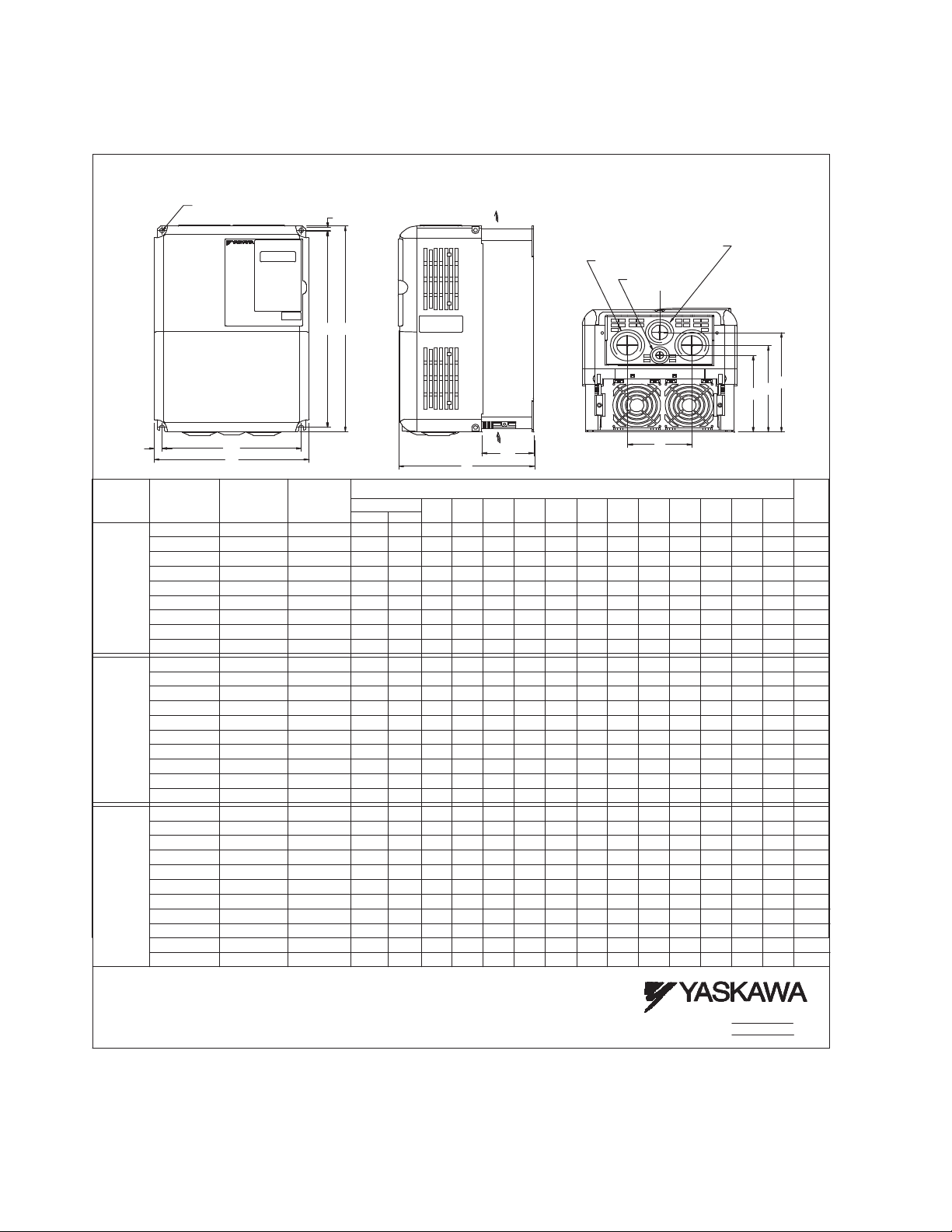
Exterior and Mounting Dimensions
DIMENSIONS: E7 (NEMA 1)
208/240V (3.6-74.8 AMPS) 480V (1.8- 40.0 AMPS)
FRONT VIEW
MOUNTING HO LES
RATED
INPUT
208V
240V
480V
W2
CIMR-E7U
20P41
20P71
22P21
23P71
27P51
20P41
20P71
22P21
23P71
25P51
27P51
40P41
40P71 2.1
42P21
43P71
45P51
FOR "A" SIZE SCREW
MODEL
21P51
20111
20151
20181
21P51
20111
20151
20181
41P51
49P01
40111
40151
W1
W
RATED
OUTPUT
CURRENT
(AMPS)
3.6
4.6
7.8
10.8
31.0
46.2
59.4
74.8 13.19
3.6
4.6
7.8
10.8
16.8
23.0
31.0
46.2
59.4
74.8
1.8
3.7
5.3
7.6
12.5
21.0
27.0
34.0
40.0 40181
NOMINAL
1/2 3/4
7.5-10
1/2 3/4
1/2 3/4 -
H2
H1
H
HP
-
1
2
3
5
15
20
25
-
1
2
3
5
7.5
10
15
20
25
1
2
3
5
7.5
10 17.0 47P51
15
20
25
30
FOR REFERENCE ONLY UNLESS PROPERLY ENDORSED.
IN ORDER TO ACHIEVE ADEQUATE COOL ING
THE DRIVE MUST BE POSITIONED TO ALLOW A MINIMUM
OF FREE AIR SPACE OF 1.2 INCHES ON SIDES AND
5 INCHES TOP AND BOTTOM
SIDE VIEW
AIR
AIR
D1
D
DIMENSIONS IN INCHES
MOUNTING
H1 W1
4.96
10.47
4.96
10.47
4.96
10.47
4.96
10.47
4.96 10.47
7.32
11.22
7.32
11.22
8.50
13.19
8.50 14.96 9.45 .30
10.47
4.96
4.96
10.47
4.96
10.47
10.47
4.96
10.47
4.96
10.47
4.96
11.22
7.32
11.22
7.32
13.19
8.50
13.19 8.50 14.96 9.45 .301/4 .47 8.27
10.47
4.96
10.47
4.96
10.47
4.96
10.47
4.96
4.96
10.47
4.96
10.47
11.22 7.327.87 11.81.28
7.32
11.22
13.19
8.50 9.45
13.19 8.50
11.02 5.51
11.02 5.51
11.02
11.02
7.87
11.81
7.87
12.20
9.45
13.78
11.02
11.02
11.02
11.02
11.02
5.51
11.02
7.87
11.81
7.87
12.20
9.45
13.78
11.02
11.02 5.51
11.02
11.02
11.02
11.02
5.51
11.817.87
13.78
9.45 13.78
W HH2
5.51
5.51
5.51
5.51
5.51
5.51
5.51
5.51
5.51
5.51
5.51
W2
.28
.28
.28
.28
.28
.28
.28
.30
.28
.28
.28
.28
.28
.28
.28
.28
.30
.28
.28
.28
.28
.28
.28
.28
.30
.30
6.30
.28
6.30
.28
6.30
.28
6.30
.28 .28 5.51 11.02 16.8
.28
7.87
.28
7.87
.47
8.27
.28
6.30
.28
6.30
.28
6.30
.28
6.30
.28
7.09
.28
7.09
.28
7.87
.28
7.87
.47
8.27
.28
6.30
.28
6.30
.28
6.30
.28
7.09
.28
7.09
.28
7.09
.28 7.87 1/44.63 6.21 3.07 1.
.28 7.871/44.63
.28
7.87
.47
8.27
.47
8.27
1.38 DIA.
(2) HOLES SIZE "J"
.87 DIA.
C
L
E
C
B
F
BOTTOM VIEW
APPROX.
WEIGHT
J
1.10
1.10
1.10
1.10
1.38
1.38
1.73
1.73 24.2
1.10
1.10
1.10
1.10
1.10
1.10
1.38
1.38
1.73
1.73
1.10
1.10 6.6
1.10
1.10
1.10
1.10
38 13.2
1.38 13.2
1.73
1.73
9.29.04
(LBS.)
6.6
6.6
6.6
6.6
13.2
15.4
24.2
6.6
6.6
6.6
6.6
8.8
8.8
13.2
15.4
24.2
24.2
6.6
6.6
8.8
8.8
8
.8
22
22
D1 B A DCE
1.54
1.54
1.54
1.54
2.32
2.58
2.58
3.07
3.07
1.54
1.54
1.54
1.54
2.32
2.32
2.58
2.58
3.07
3.07
1.54
1.54
1.54
2.32
2.32
2.32
2.58
2.58
2.58
3.07
3.07
1/4
1/4
1/4
#10
#10
#10
#10
4.63
1/4
1/4
1/4
#10
#10
#10
#10
#10
#10
4.63
1/4
1/4
#10
#10
#10
#10
#10
#10
1/4
1/4
---
3.35
---
3.35
---
3.35
---
3.35
---
5.11
4.63
5.11
5.79
5.12
5.12 .47 3.94 5.79 8.27
3.35
---
3.35
---
3.35
---
---
3.35
---
4.14
---
4.14
5.11
4.63
5.11
5.12
5.79
5.12
5.79
3.35
---
3.35
---
3.35
---
4.14
---
4.14
---
4.14
---
5.11
5.11 11.22 7.327.87 11.81.28
4.63
5.11
5.79
5.12 6.65
5.79
5.12
DR BY
APPVL.
F
1.97
4.73
1.97
4.73
1.97
4.73
1.97
4.73
5.52 #10 1.10 4.14 1.97 7.09 8.8
6.21
3.07
6.21
3.07
6.65
3.94
6.65
4.73
1.97
4.73
1.97
4.73
1.97
4.73
1.97
5.52
1.97
5.52
1.97
6.21
3.07
6.21
3.07
6.65
3.94
6.65
3.94
4.73
1.97
4.73
1.97
4.73
1.97
5.52
1.97
5.52
1.97
5.52
1.97
6.21
3.07 1.38 13.2
6.21
3.07
3.94
6.65
3.94
RIP 9.29.04
TA
Physical Installation 1 - 7
Page 18

DIMENSIONS: E7 (NEMA 1)
CURRENT
(LBS.)
APPROX.
WEIGHT
208/240V (88.0-115 AMPS) 480V (52.0-125 AMPS)
Physical Installation 1 - 8
Page 19

DIMENSIONS: E7 (PROTECTED CHASSIS)
FRONT VIEW
MOUNTING HO LES
FOR "A" SIZE SCREW
208-230V (162-415 AMPS)
480V (156-304 AMPS)
H2
H1
H
AIR
W2
W1
W
FOR REFERENCE ONLY UNLESS PROPERLY ENDORSED.
IN ORDER TO ACHIEVE ADEQUATE COOLING
THE DRIVE MUST BE POSITIONED TO ALLOW A MINIMUM
OF FREE AIR SPACE OF 1.2 I NCHES ON SIDE S AND
5 INCHES TOP AND BOTTOM
RATED
INPUT
208V
230V
480V
MODEL
CIMR-E7U
20370
20450
20550
20750
20900
21100
20370
20450
20750
20900
40900
41100
41600
RATED
OUTPUT
CURRENT
(AMPS)
162
215
312
360
415
162
192
360
156 40750
180
240
304
AIR
D1
D
NOM.
MOUNTING
HP
H1 W1
22.64
50
22.64 60
27.56
75
32.28
125
33.66
150
22.64 23.62 9.84 14.76 .49 125 3.94 11. 81 2.46 3/8
50-60
22.64 23.62 9.84 14.76 .49 139 5.12 12.99 2.46 3/8
75
27.56 28.54 12.80 17.72 .49 191 5.12 13.78 2.46 3/8
100-125 312
32.2833.46 14.57 19.69 .59 238 5.12 14.17 2.56 3/
150
125
27.56
150
27.56
200
32.28
250
33.66
DIMENSIONS IN INCHES
HWH2W2D
9.84
9.84
12.80
14.57
17.52
12.80
12.80
14.57
17.52
23.62
23.62
28.54
33.46
34.84
28.54
28.54
33.46
36.06
14.76
.49
14.76
.49
17.72
.49
19.69
.59 2.56
22.64 . 59
.49
17.72
.49 196
17.72
.59
19.69
.59
22.64
2.46
11.81
2.46
12.99 192
2.46
13.78
2.46 17.72 .49 12.80 27.56 28.54 100
13.78
14.17
2.56
14.96
13.78
2.46
2.46 3/8
13.78
14.17
2.56
14.96
2.56
DR BY
APPVL.
D1 A
3.94
3/8
5.12
3/8
5.12
3/8
5.12
3/8
5.12
3/8
5.51
3/8
8
5.12
3/8
5.12
5.12
3/8
5.51
3/8
RIP 9.29.04
TA 9.29.04
APPROX.
WEIGHT
(LBS.)
125
139
189
191
238
330
194
224
352
Physical Installation 1 - 9
Page 20

16.34
16.34
16.34 515
675
414 41850
42200
43000 58.07
51.38
51.38
56.70
50.00
50.00 400-450
500
300-350
14.37
10.63
10.63
36.06
27.95
27.95
.79
.79
.79
3.66
3.35
3.35
4.94
4.94
4.94
3/8
3/8
3/8
572
891
616
W
W1
W1
W2
H
H1
H2
AIR
D1
D
AIR
RIP 8-02
TBS 9.5.02
IN ORDER TO ACHIEVE ADEQUATE COOLING
THE DRIVE MUST BE POSITIONED TO ALLOW A MINIMUM
OF FREE AIR OF 1.2 INCHES ON SIDES AND
5 INCHES TOP AND BOTTOM
DIMENSIONS IN INCHES
OUTPUT
CURRENT
RATED
(AMPS)
INPUT
RATED
480V
MODEL
MOUNTING
HP
NOM.
H1 W 1
HWH2W2D
CIMR-E7U
D1 A
APPROX.
WEIGHT
(LBS.)
MOUNTING HOLES
FOR "A" SIZE SCREWS
DIMENSIONS: E7 (PROTECTED CHASSIS)
FOR REFERENCE ONLY UNLESS PROPERLY ENDORSED.
APPVL.
DR BY
Physical Installation 1 - 10
Page 21

Heat Loss Data
TYPE
CIMR-E7U
20P4 1.4 3.6 19 39 58 Self
20P7 1.8 4.6 26 42 68 Self
21P5 3.0 7.8 48 50 98 Self
22P2 4.1 10.8 68 59 127 Self
23P7 6.4 16.8 110 74 184 Fan
25P5 8.8 23 164 84 248 Fan
27P5 12 31 219 113 332 Fan
2011 18 46.2 357 168 524 Fan
2015 23 59.4 416 182 597 Fan
2018 29 74.8 472 208 680 Fan
2022 34 88 583 252 835 Fan
2030 44 115 883 333 1217 Fan
2037 62 162 1010 421 1430 Fan
2045 73 192 1228 499 1727 Fan
2055 82 215 1588 619 2206 Fan
2075 120 312 1956 844 2800 Fan
2090 140 360 2194 964 3157 Fan
2110 160 415 2733 1234 3967 Fan
Table 1.3 200V Class Heat Loss Data
Drive
(Inverter)
Capacity
(kVA)
Rated
Output
Current
(A)
Cooling
Fin Side
(W)
Internal
Unit Side
(W)
Total
Watt
Loss
(W)
Cooling
Method
Physical Installation 1 - 11
Page 22

Table 1.4 400V Class Heat Loss Data
TYPE
CIMR-E7U
40P4 1.4 1.8 14 39 53 Self
40P7 1.6 2.1 17 41 58 Self
41P5 2.8 3.7 36 48 84 Self
42P2 4.0 5.3 59 56 115 Fan
43P7 5.8 7.6 80 68 140 Fan
44P0 6.6 8.7 90 70 160 Fan
45P5 9.5 12.5 127 81 209 Fan
47P5 13 17 193 114 307 Fan
49P0 16 21 232 158 390 Fan
4011 21 27 232 158 390 Fan
4015 26 34 296 169 465 Fan
4018 30 40 389 201 590 Fan
4022 38 50.4 420 233 653 Fan
4024 40 52 691 297 989 Fan
4030 51 67.2 691 297 989 Fan
4037 59 77 801 332 1133 Fan
4045 73 96 901 386 1287 Fan
4055 95 125 1204 478 1682 Fan
4075 120 156 1285 562 1847 Fan
4090 140 180 1614 673 2287 Fan
4110 180 240 1889 847 2736 Fan
4132 200 260 2388 1005 3393 Fan
4160 230 304 2636 1144 3936 Fan
4185 315 414 2791 1328 3964 Fan
4220 390 515 3797 1712 5509 Fan
4300 510 675 5838 2482 8319 Fan
Drive
(Inverter)
Capacity
(kVA)
Rated
Output
Current
(A)
Cooling
Fin Side
(W)
Internal
Unit Side
(W)
Total
Watt
Loss
(W)
Cooling
Method
Physical Installation 1 - 12
Page 23

Checking and Controlling the Installation Site
Install the Drive as described below and maintain optimum conditions.
WARNING
The Drive heatsink temperature may exceed 158°F (70°C). Therefore, mount the Drive to a surface suitable
for high temperature.
Installation Site
Locate the E7 Drive as close as possible to the motor. Install the Drive under the following conditions in UL Pollution Degree
1 & 2 environments. This excludes wet locations where surfaces may become conductive due to moisture and contaminant
loading.
Table 1.5 Installation Site Specifications
Type Ambient Operating Temperature Humidity Plenum Rated
NEMA Type 1 14° F -to- 104°F ( - 1 0 -to- + 40 °C) 95%-RH-or-less-(no-condensation) Yes
Open Chassis 14° F -to- 113°F ( - 1 0 - to -+ 45 °C ) 9 5 % -RH-or-less-(no-condensation) No
Protective covers are attached to the top and bottom of the Drive. It is recommended to remove the protective covers before
operating a CIMR-E7U2030/4055 Drive and smaller in a panel to obtain the 113°F (45°C) ambient operating temperature.
Observe the following precautions when installing the Drive:
• in a clean location which is free from oil mist and dust.
• in an environment where metal shavings, oil, water, or other foreign materials will not get into the Drive enclosure.
• in a location free from radioactive materials.
• in a location free from harmful gasses and liquids.
• in a location free from excessive vibration.
• in a location free from chlorides.
• in a location away from direct sunlight.
• on a non-combustible surface.
Controlling the Ambient Temperature
To enhance the reliability of operation, the Drive should be installed in an environment free from extreme temperature
variations. If the Drive is installed in an enclosure, use a cooling fan or air conditioner to maintain the internal air temperature
below 113°
F (45°C).
Protecting the Drive from Foreign Matter
During Drive installation and project construction it is possible to have foreign matter, such as metal shavings or wire
clippings, fall inside the Drive. To prevent foreign matter from falling into the Drive, place a temporary cover over the Drive.
Always remove the temporary cover from the Drive before Start-Up. Otherwise, ventilation will be reduced, causing the Drive
to overheat.
Physical Installation 1 - 13
Page 24
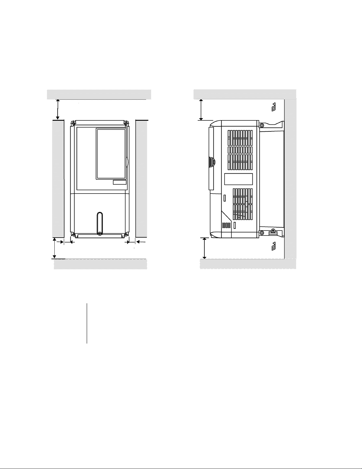
Installation Orientation and Clearances
4.75 in (120 mm. minimum)
4.75 in (120 mm. minimum)
Air
Air
Vertical ClearanceHorizontal Clearance
1.2 in
(30.5 MM.) min.
1.2 in
(30.5 mm. minimum)
1.2 in
(30.5 mm. minimum)
4.75 in (50 mm. minimum)
4.75 in (120 mm. minimum)
Install the Drive vertically so as not to reduce the cooling efficiency. When installing the Drive, always provide the following
installation clearances to allow normal heat dissipation. For 3HP, 208V/240V (CIMR-E7U22P2 and below) or 2HP, 480V
(CIMR-E7U41P5 and below), ensure that the heatsink is against a closed surface to avoid diverting cooling air around the
heatsink.
IMPORTANT
Fig 1.8 Drive Installation Orientation and Clearance
1. The same clearance is required horizontally and vertically for both Open Chassis (IP00) and NEMA
Type 1 Drives.
2. Always remove the top and bottom protection covers before installing a CIMR-E7U2018/4018 and
smaller Drive in a panel.
Always provide enough clearance for lifting eye bolts and the main circuit wiring when installing a
CIMR-E7U2022/4030 and larger Drive in a panel.
Physical Installation 1 - 14
Page 25
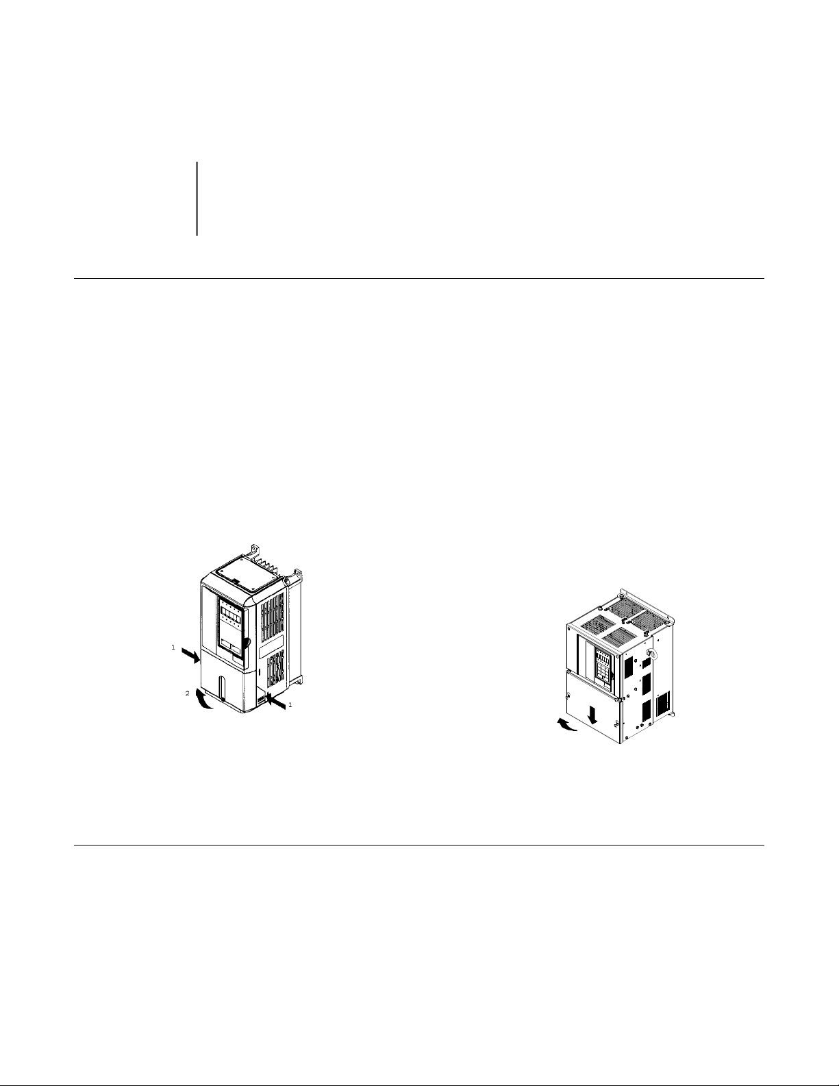
Removing and Attaching the Terminal Cover
1
2
Remove the terminal cover to connect cables to the control circuit and main circuit terminals.
Prior to removing any protective cover or wiring any part of the Drive, remove all power sources, including
main input power and control circuit power. Wait a minimum of 5 minutes after power removal, before
WARNING
Removing the Terminal Cover
Models CIMR-E7U20P4 thru 2018 (0.5HP to 25HP @ 208V/240V) and 40P4 thru 4018
(0.5HP to 30HP @ 480V)
Loosen the screw at the bottom of the terminal cover, press in on the sides of the terminal cover in the directions of arrows 1,
and then lift up on the terminal in the direction of arrow 2. Refer to Fig 1.9
Models CIMR-E7U2022 thru 2110 (30HP to 150HP @ 208V/240V) and 4030 thru 4300
(40HP to 500HP @ 480V)
removing any cover. The charge lamp located within the Drive should be off prior to working inside. Even if
the charge lamp is off, one must measure the AC input, output, and DC Bus potential to insure safe levels
prior to resuming work. Failure to adhere to this warning may result in personal injury or death.
Loosen the screws on the left and right at the top of the terminal cover, pull down the terminal cover in the direction of arrow
1 and then lift up on the terminal cover in the direction of arrow 2. Refer to Fig 1.10
Fig 1.9 Removing the Terminal Cover
Fig 1.10 Removing the Terminal Cover
Attaching the Terminal Cover
After wiring the terminal block, attach the terminal cover by reversing the removal procedure.
For Models CIMR-E7U2018/4018 and smaller, insert the tab on the top of the terminal cover into the groove on the Drive and
press in on the bottom of the terminal cover until it snaps into place.
For Drives CIMR-E7U2022/4030 and larger, insert the tab on the top of the terminal cover into the groove on the Drive, and
secure the terminal cover by lifting it up toward the top of the Drive.
Physical Installation 1 - 15
Page 26
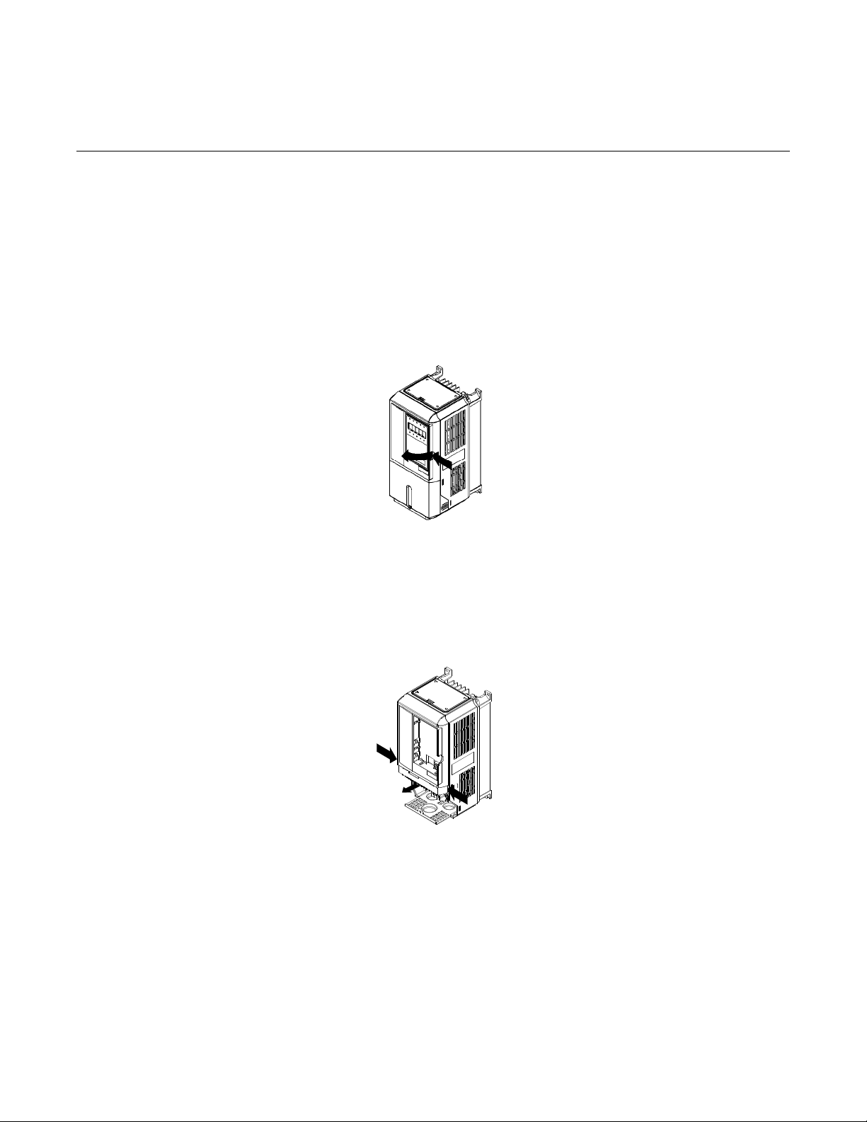
Removing/Attaching the Digital Operator and Front Cover
2
1
1
2
Models CIMR-E7U20P4 thru 2018 (0.5HP to 25HP @ 208V/240V) and 40P4 thru
4018 (0.5HP to 30HP @ 480V)
For Models CIMR-E7U2018/4018 and smaller, remove the terminal cover and then use the following procedures to remove
the Digital Operator and front cover.
Removing the Digital Operator
Press on the side of the Digital Operator in the direction of arrow 1 to unlock, then lift the Digital Operator in the direction of
arrow 2 to remove it as shown in Fig 1.11.
Fig 1.11 Removing the Digital Operator
Removing the Front Cover
Press the left and right sides of the front cover in the direction of arrows 1 and lift the bottom of cover in the direction of arrow
2 to remove it as shown in Fig 1.12.
Fig 1.12 Removing the Front Cover
Attaching the Front Cover
Mount the front cover to the Drive by performing the steps to remove the front cover in reverse order.
1. Do not mount the front cover with the Digital Operator attached to the front cover; this may cause the Digital Operator to
malfunction due to imperfect contact.
2. Insert the tab of the upper part of the front cover into the groove of the Drive and press the lower part of the front cover
onto the Drive until the front cover snaps into place.
Physical Installation 1 - 16
Page 27

Models CIMR-E7U2022 thru 2110 (30HP to 150HP @ 208V/240V) and 4030 thru
1
2
4300 (40HP to 500HP @ 480V)
For Models CIMR-E7U2022/4030 and larger, remove the terminal cover and then use the following procedures to remove the
Digital Operator and front cover.
Removing the Digital Operator
Use the same procedure for Models CIMR-E7U2018/4018 and smaller.
Removing the Front Cover
Loosen all screws on the front cover. Lift up at the location labeled 1 at the top of the control circuit terminal card and move in
the direction of arrow 2.
Fig 1.13 Removing the Front Cover
Attaching the Front Cover
Attach the front cover by reversing the procedure to remove it.
1. Confirm that the Digital Operator is not mounted on the front cover. Contact faults can occur if the cover is attached while
the Digital Operator is mounted to it.
2. Insert the tab on the top of the front cover into the slot on the Drive and press in on the cover until it snaps into place on
the Drive.
Physical Installation 1 - 17
Page 28

Attaching the Digital Operator
A
B
1
2
After attaching the front cover, mount the Digital Operator onto the Drive using the following procedure.
1. Hook the Digital Operator at A (two locations) on the front cover by moving in the direction of arrow 1 as shown in the
following illustration.
2. Press the Digital Operator in the direction of arrow 2 until it snaps in place at B (two locations).
Fig 1.14 Mounting the Digital Operator
1. Do not remove or attach the Digital Operator or mount or remove the front cover using methods other
than those described above, damage to the Digital Operator or Drive may occur.
IMPORTANT
2. Never attach the front cover to the Drive with the Digital Operator attached to the front cover. Damage to
the Digital Operator may occur. Always attach the front cover to the Drive first, and then attach the Digital
Operator to the front cover.
Physical Installation 1 - 18
Page 29

Chapter 2
Electrical Installation
This chapter describes wiring terminals, main circuit terminal connections, main
circuit terminal wiring specifications, control circuit terminals, and control circuit
wiring specifications.
Terminal Block Configuration ..................................................... 2-2
Wiring Main Circuit Terminals ................................................... 2-3
Control Wiring........................................................................... 2-12
Electrical Installation 2 - 1
Page 30

Terminal Block Configuration
Models CIMR-_ _ _ 2022 (30 HP, 208V)/
4030 (40 HP, 480V) and larger
AC MP
AMS6
-V
IG
R- M5
FM
R+RP
S1
S4SPS7 M4
+V
S3
SCS+A2
M2
SN M6
AC
A1
E(G) E(G)
MCMB
S5
M1
AC MA
M3S2 S-
AC MP
AMS6
-VIGR- M5FMR+RP
S1
S4SPS7 M4
+V
S3
SCS+A2M2SN M6
AC
A1
E(G) E(G)
MCMB
S5
M1
AC MA
M3S2 S-
Models CIMR-_ _ _ 2018 (25 HP, 208V)/
4018 (30 HP, 480V) and smaller
Ground terminal
Ground terminal
Ground terminal
Ground terminal
Charge indicator
Main circuit terminals
Main circuit terminals
Control circuit terminals
Control circuit terminals
Charge indicator
The wiring terminals are shown in Fig 2.1.
Fig 2.1 Drive Terminal Configuration
Electrical Installation 2 - 2
Page 31

Wiring Main Circuit Terminals
Applicable Wire Sizes and Closed-loop Connectors
Select the appropriate wires and crimp terminals from Table 2.1 to Table 2.2.
Table 2.1 208-240Vac Wire Sizes and Connector Specifications
Drive Model
CIMR-E7U
20P4 0.5/0.75
20P7 2
21P5 1.5/2
22P2 3
23P7 5
25P5 7.5
27P5 10
2011 15
Nominal
Hp
Terminal Symbol
R/L1, S/L2, T/L3, , 1, 2,
B1, B2, U/T1, V/T2, W/T3
R/L1, S/L2, T/L3, , 1, 2,
B1, B2, U/T1, V/T2, W/T3
R/L1, S/L2, T/L3, , 1, 2,
B1, B2, U/T1, V/T2, W/T3
R/L1, S/L2, T/L3, , 1, 2,
B1, B2, U/T1, V/T2, W/T3
R/L1, S/L2, T/L3, , 1, 2,
B1, B2, U/T1, V/T2, W/T3
R/L1, S/L2, T/L3, , 1, 2,
B1, B2, U/T1, V/T2, W/T3
R/L1, S/L2, T/L3, , 1, 2,
B1, B2, U/T1, V/T2, W/T3
R/L1, S/L2, T/L3, , 1, 2,
B1, B2, U/T1, V/T2, W/T3
Te rm i na l
Screws
M4
M4
M4
M4
M4
M4
M5
M5
Clamping
Torque
lb. in.
(N•m)
13.3
(1.5)
13.3
(1.5)
13.3
(1.5)
13.3
(1.5)
13.3
(1.5)
13.3
(1.5)
22.1
(2.5)
22.1
(2.5)
Recommended
Wire Size
AWG
2
)
(mm
14
(2.1)
14
(2.1)
14
(2.1)
12
(3.3)
10
(5.3)
10
(5.3)
8
(8)
6
(13.3)
Wire
Type
600Vac
UL Approved
vinyl-sheathed
or equivalent
2015 20
2018 25
2022 30
2030 40
R/L1, S/L2, T/L3, , 1, 2, U/T1, V/T2, W/T3
B1, B2 M5
R/L1, S/L2, T/L3, , 1, 2, U/T1, V/T2, W/T3
B1, B2 M5
R/L1, S/L2, T/L3, , 1, U/T1, V/T2,
W/T3, R1/L11, S1/L21, T1/L31
3
R/L1, S/L2, T/L3, , 1 U/T1,
V/T2, W/T3, R1/L11, S1/L21, T1/L31
3
Electrical Installation 2 - 3
M6
M6
M8
M6
M8
M6
M8
M8
M6
M8
44.3
(5.0)
22.1
(2.5)
44.3
(5.0)
88.5
(10.0)
22.1
(2.5)
44.3
(5.0)
88.5
(10.0)
45.1
(5.1)
88.5
(10.0)
88.5
(10.0)
45.1
(5.1)
88.5
(10.0)
4
(21.2)
6
(13.3)
6
(13.3)
2
(33.6)
6
(13.3)
4
(21.2)
1
(42.4)
4
(21.2)
4
(21.2)
1/0
(53.5)
4
(21.2)
2
(38)
Page 32

Table 2.1 208-240Vac Wire Sizes and Connector Specifications
Drive Model
CIMR-E7U
2037 50
2045 60
2055 75
2075 75/100
2090 125
2110 150
*Use 75°C copper wire or equivalent
Nominal
Hp
Terminal Symbol
R/L1, S/L2, T/L3, , 1 U/T1,
V/T2, W/T3, R1/L11, S1/L21, T1/L31
3
l1, s/l2
r/
R/L1, S/L2, T/L3, , 1 U/T1,
V/T2, W/T3, R1/L11, S1/L21, T1/L31
3
l1, s/l2
r/
R/L1, S/L2, T/L3, , 1
U/T1, V/T2, W/T3, R1/L11, S1/L21, T1/L31 M10
3
l1, s/l2
r/
R/L1, S/L2, T/L3, , 1
U/T1, V/T2, W/T3, R1/L11, S1/L21, T1/L31 M10
3
l1, s/l2
r/
R/L1, S/L2, T/L3, , 1
U/T1, V/T2, W/T3, R1/L11, S1/L21, T1/L31 M12
3
l1, s/l2
r/
R/L1, S/L2, T/L3, , 1
U/T1, V/T2, W/T3, R1/L11, S1/L21, T1/L31 M12
3
l1, s/l2
r/
Terminal
Screws
M10
M8
M10
M4
M10
M8
M10
M4
M10
M8
M10
M4
M10
M8
M10
M4
M12
M8
M12
M4
M12
M8
M12
M4
Clamping
To rq u e
lb. in.
(N•m)
199
(22.5)
88.5
(10.0)
203.6
(23)
12.4
(1.4)
199
(22.5)
88.5
(10.0)
199
(22.5)
12.4
(1.4)
199
(22.5)
199
(22.5)
88.5
(10.0)
199
(22.5)
12.4
(1.4)
199
(22.5)
199
(22.5)
88.5
(10.0)
199
(22.5)
12.4
(1.4)
347
(39.2)
347
(39.2)
88.5
(10.0)
347
(39.2)
12.4
(1.4)
347
(39.2)
347
(39.2)
88.5
(10.0)
347
(39.2)
12.4
(1.4)
Recommended
Wire Size
AWG
2
)
(mm
4/0
(100)
4
(22)
2/0
(67.4)
14
(2.1)
300
(152)
4
(21.2)
3/0
(85)
14
(2.1)
1/0 X 2P
(53.5 X 2P)
1/0 X 2P
(53.5 X 2P)
2/0
(67.4)
4/0
(107.2)
14
(2.1)
4/0 X 2P
(80 X 2P)
3/0 X 2P
(85 X 2P)
2/0
(67.4)
2/0 X 2P
(67.4 X 2P)
14
(2.1)
250 x2P
(127 x2P)
4/0 X 2P
(107.2 X 2P)
2/0
(67.4)
2/0 X 2P
(67.4 X 2P)
14
(2.1)
300 X 2P
(152 X 2P)
300 X 2P
152 X 2P
2/0
(67.4)
4/0 X 2P
(107.2 X 2P)
16
(1.25)
Wire
Typ e
600Vac
UL Approved
vinyl-sheathed
or equivalent
Electrical Installation 2 - 4
Page 33

Table 2.2 480Vac Wire Sizes and Connector Specifications
Drive Model
CIMR-E7U
40P4 0.5/0.75
40P7 1
41P5 1.5/2
42P2 3
43P7 5
45P5 7.5
47P5 10
49P0/4011 15/20
4015 25
Nominal
Hp
Termin al S y m b o l
R/L1, S/L2, T/L3, , 1, 2,
B1, B2, U/T1, V/T2, W/T3
R/L1, S/L2, T/L3, , 1, 2,
B1, B2, U/T1, V/T2, W/T3
R/L1, S/L2, T/L3, , 1, 2,
B1, B2, U/T1, V/T2, W/T3
R/L1, S/L2, T/L3, , 1, 2,
B1, B2, U/T1, V/T2, W/T3
R/L1, S/L2, T/L3, , 1, 2,
B1, B2, U/T1, V/T2, W/T3
R/L1, S/L2, T/L3, , 1, 2,
B1, B2, U/T1, V/T2, W/T3
R/L1, S/L2, T/L3, , 1, 2,
B1, B2, U/T1, V/T2, W/T3
R/L1, S/L2, T/L3, , 1, 2,
B1, B2, U/T1, V/T2, W/T3
R/L1, S/L2, T/L3, , 1, 2,
B1, B2, U/T1, V/T2, W/T3
Terminal
Screws
M4
M4
M4
M4
M4
M4
M4
M5
M5
Clamping
To rq u e
lb. in.
(N•m)
13.3
(1.5)
13.3
(1.5)
13.3
(1.5)
13.3
(1.5)
13.3
(1.5)
13.3
(1.5)
13.3
(1.5)
22.1
(2.5)
22.1
(2.5)
Recommended
Wire Size AWG
2)
(mm
14
(2.1)
14
(2.1)
14
(2.1)
14
(2)
14
(2.1)
14
(2.1)
12
(3.5)
14
(2)
10
(5.5)
12
(3.5)
8
(8)
10
(5.5)
8
(8)
Wire Type
600Vac
UL Approved
vinyl-sheathed
or equivalent
4018 30
4024/4030 40/50
4037 60
4045 75
R/L1, S/L2, T/L3, , 1, 3, U/T1, V/T2, W/T3,
B1, B2 M5
R/L1, S/L2, T/L3, , 1, 3, U/T1, V/T2, W/T3,
R/L1, S/L2, T/L3, , 1, U/T1, V/T2, W/T3, R1/L11,
R/L1, S/L2, T/L3, , 1, U/T1, V/T2, W/T3, R1/L11,
R1/L11, S1/L21, T1/L31
S1/L21, T1/L31
3
S1/L21, T1/L31
3
Electrical Installation 2 - 5
M6
M6
M6
M8
M8
M6
M8
M8
M6
M8
44.3
(5.0)
21.1
(2.5)
44.3
(5.0)
44.3
(5.0)
88.5
(10.0)
88.5
(10.0)
44.3
(5.0)
88.5
(10.0)
88.5
(10.0)
44.3
(5.0)
88.5
(10.0)
6
(13.3)
8
(8)
6
(13.3)
3
(26.7)
6
(13.3)
2
(33.6)
4
(21.2)
4
(21.2)
2
(33.6)
4
(21.2)
4
(21.2)
Page 34

Table 2.2 480Vac Wire Sizes and Connector Specifications
Drive Model
CIMR-E7U
4055 100
4075 125
4090 150
4110 200
4160 250
Nominal
Hp
Terminal Symbol
R/L1, S/L2, T/L3, , 1, U/T1, V/T2,
W/T3, R1/L11, S1/L21, T1/L31
3
R/L1, S/L2, T/L3, , 1
U/T1, V/T2, W/T3, R1/L11, S1/L21, T1/L31 M10
3
l1, s200/l
r/
R/L1, S/L2, T/L3, , 1
U/T1, V/T2, W/T3, R1/L11, S1/L21, T1/L31 M10
r/
R/L1, S/L2, T/L3, , 1
U/T1, V/T2, W/T3, R1/L11, S1/L21, T1/L31 M10
r/
R/L1, S/L2, T/L3, , 1
U/T1, V/T2, W/T3, R1/L11, S1/L21, T1/L31 M12
r/
200, s400/l2400 M4
2
3
l1, s200/l
200, s400/l2400 M4
2
3
l1, s200/l
200, s400/l2400 M4
2
3
l1, s200/l
200, s400/l2400 M4
2
Te rm i na l
Screws
M8
M6
M8
M10
M8
M12
M10
M8
M12
M10
M8
M12
M12
M8
M12
Clamping
Torque
lb. in.
(N•m)
88.5
(10.0)
44.3
(5.0)
88.5
(10.0)
199
(22.5)
199
(22.5)
88.5
(10.0)
347
(39.2)
12.4
(1.4)
199
(22.5)
199
(22.5)
88.5
(10.0)
347
(39.2)
12.4
(1.4)
199
(22.5)
199
(22.5)
88.5
(10.0)
347
(39.2)
12.4
(1.4)
347
(39.2)
347
(39.2)
88.5
(10.0)
347
(39.2)
12.4
(1.4)
Recommended
Wire Size AWG
2)
(mm
2/0
(33.6)
4
(21.2)
1
(42.4)
4/0
(107.2)
3/0
(85)
4/0
(107.2)
1/0
(53.5)
14
(2.1)
250
(127)
4/0
(107.2)
4/0
(107.2)
2/0
(67.4)
14
(2.1)
2/0 X 2P
(67.4 X 2P)
1/0 X 2P
(53.5 X 2P)
2/0
(67.4)
4/0
(107.2)
14
(2.1)
4/0 X 2P
(107.2 X 2P)
3/0 X 2P
(85 X 2P)
2/0
(67.4)
1/0 X 2P
(53.5 X 2P)
14
(2.1)
Wire Type
600Vac
UL Approved
vinyl-sheathed
or equivalent
Electrical Installation 2 - 6
Page 35

Table 2.2 480Vac Wire Sizes and Connector Specifications
3
Drive Model
CIMR-E7U
4185 300/350
4220 400/450
4300 500+
*Use 75°C copper wire or equivalent.
Nominal
Hp
Terminal Symbol
R/L1, S/L2, T/L3, , 1
U/T1, V/T2, W/T3, R1/L11, S1/L21, T1/L33 M8
3
l1, s200/l
r/
R/L1, S/L2, T/L3, , 1
U/T1, V/T2, W/T3, R1/L11, S1/L21, T1/L33 M8
r/
R/L1, S/L2, T/L3, , 1
U/T1, V/T2, W/T3, R1/L11, S1/L21, T1/L33 M8
r/
200, s400/l2400 M4
2
3
l1, s200/l
200, s400/l2400 M4
2
3
l1, s200/l
200, s400/l2400
2
Te rm i na l
Screws
M8
M8
M16
M8
M8
M16
M8
M8
M8
M16
Clamping
Torque
lb. in.
(N•m)
88.5
(10.0)
88.5
(10.0)
88.5
(10.0)
867.4
(98.0)
12.4
(1.4)
88.5
(10.0)
88.5
(10.0)
88.5
(10.0)
867.4
(98.0)
12.4
(1.4)
88.5
(10.0)
88.5
(10.0)
88.5
(10.0)
867.4
(98.0)
12.4
(1.4)
Recommended
Wire Size AWG
2)
(mm
300 X 2P
(152 X 2P)
300 X 2P
(152 X 2P)
2/0
(67.4)
3/0 X 2P
(85 X 2P)
14
(2.1)
500 X 2P
(253 X 2P)
400 X 2P
(203 X 2P)
2/0
(67.4)
250 X 2P
(127 X 2P)
14
(2.1)
700 X 2P
(355 X 2P)
600 X 2P
(304 X 2P)
2/0
(67.4)
400 X 2P
(203 X 2P)
14
(2.1)
Wire Type
600Vac
UL Approved
vinyl-sheathed
or equivalent
IMPORTANT
WARNING
Determine the wire size for the main circuit so that line voltage drop is within 2% of the rated voltage. Line
voltage drop is calculated as follows:
Line voltage drop (V) =
Prior to removing any protective cover or wiring any part of the Drive, remove all power sources, including
main input power and control circuit power. Wait a minimum of 5 minutes after power removal, before
x wire resistance (Ω/km) x wire length (m) x current (A) x 10
-3
removing any cover. The charge lamp located within the Drive should be off prior to working inside. Even if
the charge lamp is off, one must measure the AC input, output, and DC Bus potential to insure safe levels
prior to resuming work. Failure to adhere to this warning may result in personal injury or death.
Electrical Installation 2 - 7
Page 36

Main Circuit Terminal Functions
Main circuit terminal functions are summarized according to terminal symbols in Table 2.3. Wire the terminals correctly for
the desired purpose.
Table 2.3 Main Circuit Terminal Functions (208-240Vac and 480Vac)
Purpose Terminal Designation
R/L1, S/L2, T/L3 20P4 to 2110 40P4 to 4300
Main circuit power input
R1/L11, S1/L21, T1/L31 2022 to 2110 4030 to 4300
Drive outputs U/T1, V/T2, W/T3 20P4 to 2110 40P4 to 4300
Model: CIMR-E7U_ _ _ _
208-240Vac 480Vac
DC power input
DC reactor connection
Ground 20P4 to 2110 40P4 to 4300
1,
1, 2
20P4 to 2110 40P4 to 4300
20P4 to 2018 40P4 to 4018
Electrical Installation 2 - 8
Page 37

Main Circuit Configurations 208-240Vac
Power
supply
Control
circuits
{
1
Note
CIMR-_ _ _ 20P4 to 2018
(1/2 Hp to 25 Hp)
Power
supply
Control
circuits
{
Notes
1 & 3
CIMR-_ _ _ 2037 to 2110
(50 Hp to 150 Hp)
Power
supply
Control
circuits
{
Notes
1 & 3
The 208-240Vac main circuit configurations of the Drive are shown in Table 2.4.
Table 2.4 Drive Main Circuit Configurations
208-240 VAC
CIMR-_ _ _ 2022 and 2030
(30 Hp to 40 Hp)
Note1. Input fuses or molded case circuit breakers are required for proper branch circuit protection for all Drives. Failure
2. Control power is supplied internally from the main circuit DC power supply for all Drives.
3. Consult your Yaskawa representative before using 12-pulse rectification.
---
to use recommended fuses/circuit breakers (See Appendix E) may result in damage to the wiring, Drive and/or
personal injury.
Electrical Installation 2 - 9
Page 38

Main Circuit Configurations 480Vac
Power
supply
Control
circuits
{
Note
1
CIMR-_ _ _ 4024 to 4055
(40 Hp to 100 Hp)
Power
supply
Control
circuits
{
Notes
1 & 3
Power
supply
Control
circuits
{
Notes
1 & 3
3
CIMR-_ _ _ 4075 to 4160 and CIMR-_ _ _ 4185 to 4300
(125 Hp to 500 Hp)
The 480Vac main circuit configurations of the Drive are shown in Table 2.5.
Table 2.5 Drive Main Circuit Configurations
480 VAC
CIMR-_ _ _ 40P4 to 4018
(1/2 Hp to 30 Hp)
Note1. Input fuses or molded case circuit breakers are required for proper branch circuit protection for all Drives. Failure
to use recommended fuses/circuit breakers (See Appendix E) may result in damage to the wiring, Drive and/or
personal injury.
2. Control power is supplied internally from the main circuit DC power supply for all Drives.
3. Consult your Yaskawa representative before using 12-pulse rectification.
---
Electrical Installation 2 - 10
Page 39

Cable Length between Drive and Motor
NO
OK
OK
NOT OK
The E7 should be installed as close as possible to the motor to minimize the length of load side power cable needed between
the Drive and the motor.
If the cable between the Drive and the motor is long, the high-frequency leakage current will increase, causing the Drive
output current to increase as well. This may affect peripheral devices. To prevent this, reduce the cable length whenever
possible, or if necessary, adjust the carrier frequency (set in C6-02) as shown in Table 2.6.
The line side power cables, load side power cables and the control wiring should all be run in a separate conduit. Careful attention to this recommended design practice will avoid many potential motor and Drive related problems.
Table 2.6 Motor Cable Length vs. Carrier Frequency (C6-02)
Motor Cable Length 164 ft. (50m) maximum 328 ft. (100m) maximum More than 328 ft.(100m)
Carrier Frequency 15kHz maximum 10kHz maximum 5kHz maximum
(See the limitations on carrier frequency, based on Drive capacity and model number in Appendix B).
Ground Wiring
Observe the following precautions when connecting the ground wire:
1. 208-240Vac Drives should have a ground connection with resistance of less than 100Ω.
2. 480Vac Drives should have a ground connection with resistance of less than 10Ω.
3. Do not share the ground wire with other devices, such as motors or large-current electrical equipment.
4. Always use a ground wire that complies with technical standards on electrical equipment and minimize the length of the
ground wire. Leakage current flows through the Drive. Therefore, if the distance between the ground rod and the ground
terminal is too long, potential on the ground terminal of the Drive will become unstable.
5. When using more than one Drive, be careful not to loop the ground wire. See Fig 2.2.
Fig 2.2 Ground Wiring Examples
Control Circuit Ground Terminals
The removable Drive control terminal card provides two ground terminals (marked TB3 and TB4) to accept the control wire
shield connection. The control wire shield should be connected on this end only, the opposite end should be isolated with
electrical tape.
IMPORTANT
Grounding of the E7 enclosure and motor is required for proper system operation.
Electrical Installation 2 - 11
Page 40

Control Wiring
Signal Terminal Connections
0-10Vdc A1 to AC
4-20mA
or
0-10Vdc
A2 to AC
E(G)
+ V + 1 5 V D C , 20 m A
A 1 0- 1 0 V D C (2 0K )
A 2 H 3 - 0 8
4 - 20 m A (2 50 K )
[0 to + 10 V (2 0 K )]
AC
E7
4 to 20m A
PP
External
Frequency
R eference
2k
2k
(P=Pair)
External
Frequency
Reference
E (G)
2kΩ
2k
P P
4 to 20m A
+V +15VDC, 20mA
A1 0-10VDC (20k Ω)
A2 H3-08
4-20m A (250K Ω)
[0 to +10V (20K Ω)]
AC
Control Circuit Wire Sizes
The auto mode speed reference (speed command) field wiring connection is made to E7 Drive terminals A1 or A2 (signal
positive), AC (signal common) and G (shield). Keep this lead length as short as possible to maintain signal quality. Insulated
twisted shielded pair wire (2 conductor # 18 ga, Belden 8760 or equivalent) is required. Do not run these wires in the same
conduit as other AC power or control wires. The shield must be connected on this end only, stub and isolate the other end. The
A2 signal employed is 4 to 20 mA with parameter H3-08 set for “2: 4 - 20 mA”. For 0 to 10 VDC, parameter H3-08 is set for
“0: 0 - 10 VDC” and the E7 control board DIP switch S1-2 must be in the OFF position. (See Fig 2.4).
For remote operation, keep the length of the control wiring to 50m or less. Separate the control wiring from high-power lines
(input power, motor leads or relay sequence circuits) to reduce noise induction from peripheral devices.
When setting speed commands (frequency references) from an external speed potentiometer (and not from the Digital Operator), use shielded twisted-pair wires and ground the shield to terminal E(G), as shown in Fig 2.3. Terminal numbers and wire
sizes are shown in Table 2.7.
Ω
Ω
Ω
Ω
Fig 2.3 Analog Input Terminal Configuration
Table 2.7 Terminal Numbers and Wire Sizes (Same for all Drives)
Tightening
Terminals
Te rm in a l
Screws
Torque
lb-in
(N•m)
S1, S2, S3, S4, S5, S6, S7
SN, SC, SP, +V, A1, A2,
AC, MI, M2, M3, M4,
MA, MB, MC, FM, AC,
Phoenix
*3
type
4.2 to 5.3
(0.5 to 0.6)
AM, R+, R-, S+, S-, IG
E(G) M3.5
*1. Use shielded twisted-pair cables to input an external speed command.
*2. Yaskawa recommends using straight solderless terminals on digital inputs to simplify wiring and improve reliability.
*3. Yaskawa recommends using a thin-slot screwdriver with a 3.5 mm blade width.
7.0 to 8.8
(0.8 to 1.0)
Possible
Wire Sizes
AWG (mm2)
Stranded
wire:
26 to 16
(0.14 to 1.5)
20 to 14
(0.5 to 2*2)
Recommended
Wire Size AWG
(mm2)
18
(0.75)
12
(1.25)
• Shielded, twisted-pair wire
• Shielded, polyethylene-covered,
Wire Type
*1
vinyl sheath cable
Electrical Installation 2 - 12
Page 41

Wiring Checks
After all wiring is completed, perform the following checks:
1. Is all wiring correct?
2. Have all wire clippings, screws or other foreign material been removed from the Drive enclosure?
3. Are all terminal screws tight?
Electrical Installation 2 - 13
Page 42

Control Circuit Terminal Functions
The factory default functions of the control circuit terminals for 2-wire control are shown in Table 2.8.
Table 2.8 Control Circuit Terminals
Typ e No. Signal Name Description Signal Level
S1 Forward run/stop command Forward run when CLOSED; stopped when OPEN.
S2 Reverse run/stop command Reverse run when CLOSED; stopped when OPEN.
S3 External fault input Fault when CLOSED.
Digital
input
signals
Analog
input
signals
Digital
output
signals
Analog
output
signals
RS-485/
422
S4 Fault reset Reset when CLOSED
Multi-step speed reference 1
S5
S6 Multi-step speed reference 2
S7 Jog frequency reference Jog frequency when CLOSED.
SN
SC
SP
+V +15Vdc power supply +15Vdc power supply for analog inputs or transmitters
A1
A2 Multi-function analog input
AC Analog common – –
E(G)
M1
M2
M3
M4
MA
MB
MC
FM Multi-function analog output
AC Analog common –
AM Multi-function analog output
R+
R-
S+
S-
IG Signal common - -
(Master/auxiliary switch)
Digital input common
Analog input or
Speed Command
Shield wire, optional ground
line connection point
During Run
(N.O. contact)
Remote/Auto Operation
(N.O. contact)
Fault output signal
(SPDT)
Modbus
communication input
Modbus
communication output
Auxiliary frequency reference
when CLOSED.
Multi-step setting 2 when
CLOSED.
Refer to Table 2.10 for connection details.
0 to +10Vdc/100% 0 to +10 V(20 kΩ)
4 to 20 mA/100%
0 to +10Vdc/100% (H3-0
––
CLOSED during operation
CLOSED when local control
MA/MC: CLOSED during fault condition
MB/MC: OPEN during fault condition
(output frequency)
0 to +10Vdc/100% frequency
(output current)
0 to +10Vdc/100% Drive's rated
output current
For 2-wire RS-485, jumper R+ and S+ and
jumper R- and S-.
Multi-function
digital inputs
Functions set by
H1-01 to H1-05.
Function set by
H3-09.
Multi-function
digital output
Function set by
H2-01.
Multi-function
digital output
Function set by
H2-02.
Multi-function
analog monitor 1
Function set by
H4-01
Multi-function
analog monitor 2
Function set by
H4-04
24 Vdc, 8 mA
Photocoupler isolation
(Max. current: 20 mA)
4 to 20 mA(250Ω)
0 to +10 V(20kΩ)
Dry contacts
Contact capacity:
1 A max. at 250Vac
1 A max. at 30Vdc
Dry contacts
Contact capacity:
1 A max. at 250Vac
1 A max. at 30Vdc
0 to +10Vdc max. ±5%
2 mA max.
Differential input,
PHC isolation
Differential input,
PHC isolation
+15Vdc
Electrical Installation 2 - 14
Page 43
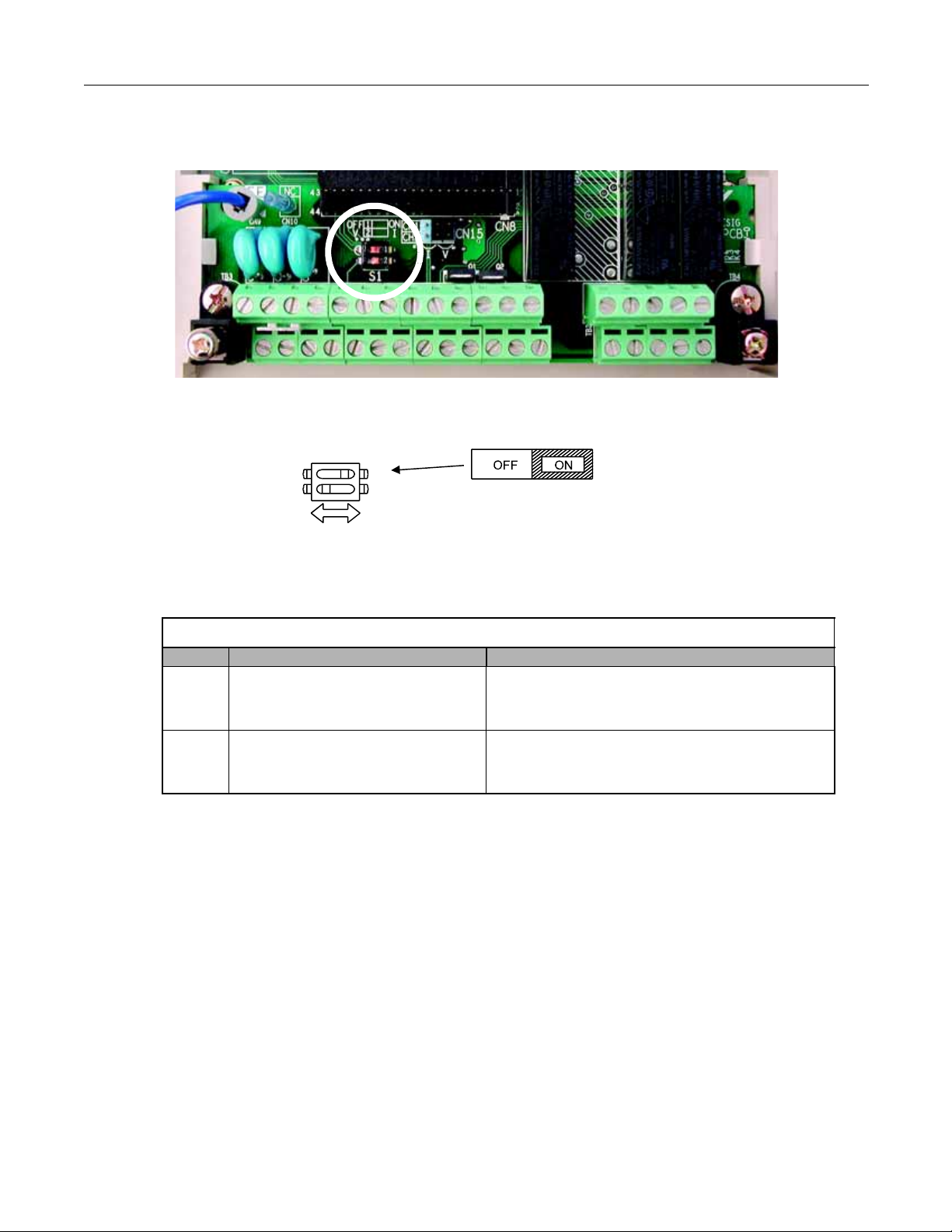
DIP Switch S1
S1
1
Terminating
resistance
DIP Switch S1 located on
terminal board.
2
1
DIP Switch S1 is described in this section. The functions of DIP switch S1 are shown in Table 2.9.
Fig 2.4 DIP Switch S1 Location
Table 2.9 DIP Switch S1
Name Function Setting
OFF: No terminating resistance
S1-1 RS-485 and RS-422 terminating resistance
ON: Terminating resistance of 110Ω
Factory Default = OFF
OFF: 0-10 Vdc (internal resistance: 20KΩ)
S1-2 Input method for analog input A2
ON: 4-20mA (internal resistance: 250Ω)
Factory Default = ON
Electrical Installation 2 - 15
Page 44

Shunt Connector CN15
The shunt connector CN15 is described in this section. Shunt connector along with parameters H4-07 and H4-08 select the signal range of the analog output terminals FM and AM.
Shunt connector CN15 is only available when the optional Terminal Card with the 4-20mA Analog Output Monitor is installed
(Model No. ETC618120). See Chapter 7, Maintenance, for installation of the optional Terminal Card.
The function of various shunt connector CN15 configurations is shown in Table 2.10.
Fig 2.5 Shunt Connector CN15 Location
Table 2.10 Shunt Connector CN15 Configuration Options
CN15 Analog Output Monitor Configurations
Voltage Output (0-10Vdc) for terminals FM-AC (CH1) and AM-AC (CH2)
Current Output (4-20mA) for terminals FM-AC (CH1) and AM-AC (CH2)
Voltage Output (0-10Vdc) for terminals FM-AC (CH1)
Current Output (4-20mA) for terminals AM-AC (CH2)
Current Output (4-20mA) for terminals FM-AC (CH1)
Voltage Output (0-10Vdc) for terminals AM-AC (CH2)
The software configuration for the analog output monitor signal type is listed below:
Parameter
No.
H4-07
H4-08
Parameter Name
Digital Operator Display
Terminal FM Signal Level
Selection
AO Level Select1
Terminal AM Signal Level
Selection
AO Level Select2
Description
0: 0 - 10 V
2: 4-20 mA
0: 0 - 10 V
2: 4-20 mA
Setting
Range
0 or 2 0 Programming
0 or 2 0 Programming
Factory
Setting
Menu
Location
Electrical Installation 2 - 16
Page 45

Sinking/Sourcing Mode
Internal Power Supply – Sinking Mode
(Factory Default)
External Power Supply – Sinking Mode
External +24V
Internal Power Supply – Sourcing Mode
External Power Supply – Sourcing Mode
External +24V
The input terminal logic can be switched between sinking mode (0V common) and sourcing mode (+24V common) by using
the terminals SN, SC, and SP. An external power supply can also be connected, providing more freedom in signal input
methods.
Table 2.11 Sinking/Sourcing Mode and Input Signals
Electrical Installation 2 - 17
Page 46

Terminal Connections
Connections to Drive terminals are shown in Fig 2.6.
18
P4
Fig 2.6 Terminal Connections
Electrical Installation 2 - 18
Page 47

Control Circuit Wiring Precautions
Shield sheath
Insulation
Connect to shield sheath
terminal E(G) at Drive
Insulate with tape
Do not connect here.
Observe the following precautions when wiring control circuits:
1. Separate control wiring from power/motor wiring (terminals R/L1, S/L2, T/L3, U/T1, V/T2, W/T3, , 1, 2, and
3) and other high-power lines.
2. Separate wiring for control circuit terminals MA, MB, MC, M1, M2, M3, and M4 (digital outputs) from wiring to other
control circuit terminals.
3. If using an optional external power supply, ensure it is a UL Listed Class 2 power supply source.
4. Use twisted-pair or shielded twisted-pair cables for control circuits to prevent operating faults. Prepare cable ends as
shown in Fig 2.7.
5. Connect the shield wire to terminal E(G).
6. Insulate the shield with tape to prevent contact with other signal lines and equipment.
Fig 2.7 Preparing the Termination of Shielded Twisted-pair Cables
Electrical Installation 2 - 19
Page 48

Field Wiring Diagram
Use this diagram to document field wiring. It may be helpful to copy this page.
Fig 2.8 Field Wiring Diagram
Electrical Installation 2 - 20
Page 49

Chapter 3
Digital Operator
This chapter describes the displays and functions of the Digital Operator.
Digital Operator Display ............................................................. 3-2
Digital Operator Keys................................................................. 3-3
Drive Mode Indicators................................................................ 3-5
Drive Main Menu........................................................................ 3-7
Quick Setting Menu (-QUICK-) ................................................ 3-12
Programming Menu (-ADV-) .................................................... 3-13
Example of Changing a Parameter.......................................... 3-15
Digital Operator 3 - 1
Page 50
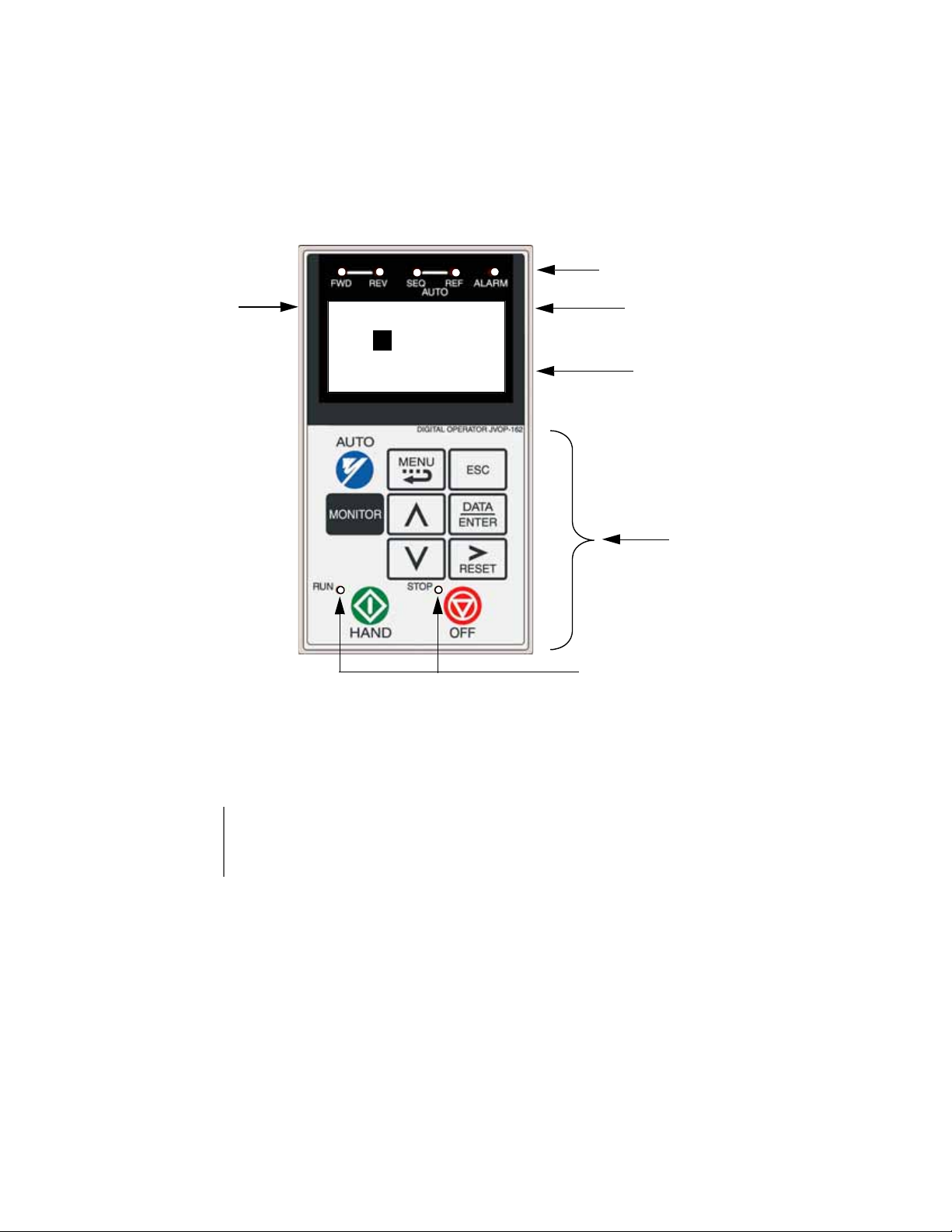
Digital Operator Display
Drive Mode Indicators
See Table 3.2
Data Display
Displays monitor data, parameter numbers and settings
Key Descriptions
See Table 3.1
RUN & STOP Indicators
See Tables 3.5 and 3.6
Ready Display
Drive can operate when a drive command is input
-DRIVE- Rdy
Frequency Ref
U1-01= 60.00Hz
- - - - - - - - - - - - - - - - - - - - - - - - - - - - -
U1-02= 60.00Hz
U1-03= 10.05A
1 line x 13 characters
3 lines x 16 characters
Menu Display
See Table 3.7
The Digital Operator is used for programming, operating, and monitoring drive operation. By default the E7 Drive will not run
unless the digital operator is securely attached to the Drive.
The various items included on the Digital Operator are described below.
WARNING
Fig 3.1 Digital Operator Component Names and Functions
The digital operator can be used to operate (start) the Drive. Incorrect programming and/or improper key
selection on the digital operator may result in the Drive starting unexpectedly. Prior to making any adjustments
with the digital operator, insure that all personnel are clear from the Drive, motor, and machine. Also, insure
that all covers, couplings, pulleys, shaft keys, etc. are secure.
Digital Operator 3 - 2
Page 51

Digital Operator Keys
The names and functions of the Digital Operator Keys are described in Table 3.1.
Table 3.1 Digital Operator Keys
Key Name Function
• Pressing the AUTO key will put the Drive in the “Auto” mode.
• In the “Auto” mode, the Drive will be capable of starting/stopping depending on the
setting of parameter “b1-02” (Run Command Selection).
• In the “Auto” mode, the Drive speed command (frequency reference) will depend
on the setting of parameter “b1-01” (Frequency Reference Selection).
• If the OFF key is pressed, the “Auto” mode frequency reference will continue to be
displayed on the keypad.
AUTO Key
• Pressing the AUTO key will start the Drive if the run command is already closed.
• If the Drive is running in the “Auto” mode and the OFF key is pressed, the Drive
will stop. If the run command remains closed, pressing the AUTO key will restart
the Drive.
• While the Drive is running, the run command can be opened to stop and closed to
restart without taking the Drive out of the “Auto” mode.
• The Drive must be in a stopped condition before it can be transferred to “Auto” or
“Hand” mode, unless b1-13=1.
MENU Key Scrolls through the five main menus.
ESCAPE Key Returns to the previous display, before the DATA/ENTER key was pressed.
MONITOR Key
INCREASE Key
DECREASE Key
SHIFT/RESET Key
Selects the monitor mode from the Operation (-DRIVE-), Quick Setting (-QUICK-),
Programming (-ADV-) and Modified Constants (-VERIFY-) menus.
Increases parameter numbers and set values.
Used to move to the next item or data value.
Decreases parameter numbers and set values.
Used to move to the previous item or data value.
Selects the digit to be changed. The selected digit will blink.
Also resets the Drive when a fault has occurred.
DATA/ENTER Key Pressed to enter menus and parameters as well as to set values.
Digital Operator 3 - 3
Page 52

Table 3.1 Digital Operator Keys
Key Name Function
• Pressing the HAND key will put the Drive in the “Hand” mode and start the
Drive.
• In the “Hand” mode, the drive speed command will depend on the setting of
HAND Key
parameter “b1-12” (Hand Frequency Reference Selection).
• If the OFF key is pressed, the “Hand” mode speed command will continue to be
displayed on the keypad.
• The Drive must to be in a stopped condition before it can be transferred to
“Hand” or “Auto” mode, unless b5-13=1.
OFF Key
Stops Drive operation, following the stopping method as programmed in parameter
b1-03.
Digital Operator 3 - 4
Page 53

Drive Mode Indicators
The definition of the Drive mode indicators are shown in Table 3.2.
Table 3.2 Drive Mode Indicators
Indicator Definition
FWD Lit when a forward run command is input and when Drive is in “Hand” Mode.
REV Lit when a reverse run command is input.
AUTO SEQ Lit when set up for remote run command. See Table 3.3
AUTO REF Lit when set up for remote speed command. See Table 3.4
ALARM Lit when a fault has occurred. Flashes when an alarm has occurred.
AUTO Sequence (SEQ) Indicator
The status of the AUTO “Sequence” (SEQ) indicator is shown in Table 3.3. This indicator is always “Off” when the Drive is in
the “Hand” mode. When the Drive is in the “Auto” mode, the SEQ indicator status is dependent on the setting of parameter
“b1-02” (Run Command Selection).
Table 3.3 AUTO Sequence (SEQ) Indicator
Indicator Status Hand Mode Auto Mode
Parameter “b1-02” (Run Command Selection) is set to terminal strip,
communications, or an option board as indicated below:
On
N/A
Off
b1-02=1 (Terminals)
=2 (Communications)
=3 (Option PCB)
Parameter “b1-02” (Run Command Selection) is set to digital operator
as indicated below:
b1-02=0 (Operator)
Digital Operator 3 - 5
Page 54

AUTO Reference (REF) Indicator
The status of the AUTO “Reference” (REF) indicator is shown in Table 3.4. This indicator is always “Off” when the Drive is
in the “Hand” mode. When the Drive is in the “Auto” mode, the REF indicator status is dependent on the setting of parameter
“b1-01” (Frequency Reference Selection).
Table 3.4 AUTO Reference (REF) Indicator
Indicator Status Hand Mode Auto Mode
Parameter “b1-01” (Frequency Reference Selection) is set to terminal
strip, communications, or an option board as indicated below:
On
N/A
Off
b1-01=1 (Terminals)
=2 (Communications)
=3 (Option PCB)
Parameter “b1-01” (Frequency Reference Selection) is set to digital
operator as indicated below:
b1-01=0 (Operator)
Run Indicator
The status of the “RUN” indicator is shown in Table 3.5 when the Drive is in either the “Hand” or “Auto” mode.
Table 3.5 RUN Indicator
Indicator Status Condition
On Drive is running
Blinking Drive is decelerating to a stop
Off Drive is stopped
Stop Indicator
The status of the “STOP” indicator is shown in Table 3.6 when the Drive is in either the “Hand” or “Auto” mode.
Table 3.6 STOP Indicator
Indicator Status Condition
On Drive is decelerating to a stop or stopped
Blinking
Off Drive is running
Drive is in a run condition but the frequency reference is zero or
Drive is running in “Auto” mode and OFF has been pressed
Digital Operator 3 - 6
Page 55

Drive Main Menu
The Drive’s parameters and monitoring functions are organized into menu groups that make it easier to read and set
parameters. The Drive is equipped with five menu selections. The five selections and their primary functions are shown in
Table 3.7 and are directly available by pressing the MENU key.
Table 3.7 Drive Main Menu
Main Menu Primary Function(s)
Operation
- DRIVE -
Quick Setting
- QUICK -
Programming
- ADV -
Modified Constants
- VERIFY -
Auto-Tuning
- A.TUNE -
The Drive can be run in this menu.
Use this menu for monitoring values such as frequency reference or output current, displaying fault history or displaying the fault traces.
The Drive can be programmed in this menu.
Use this menu to set/read the most commonly used parameters.
The Drive can be programmed in this menu.
Use this menu to set/read every parameter.
The Drive can be programmed in this menu.
Use this menu to set/read the parameters that have been modified from their factory default settings.
The Drive can be programmed in this menu.
Use this menu to auto-tune the Drive in order to optimize motor performance as well as utilize the
bi-directional speed search feature.
Digital Operator 3 - 7
Page 56

Main Menu Structure
-DRIVE-
** Main Menu **
- - - - - - - - - - - - - Operati on
-DRIVE-
** Main Menu **
- - - - - - - - - - - - - -
Quick Setting
-DRIVE-
** Main Menu **
- - - - - - - - - - - - - -
Pro grammi ng
-DRIVE-
** Main Menu **
- - - - - - - - - - - - - -
Modi fied Con st s
-DRIVE-
** Main Menu **
- - - - - - - - - - - - - -
Auto-Tuning
-QUICK-
-ADV-
-VERIFY-
-A.TUNE-
1
The menu selection display will appear when the MENU key is pressed from a monitor or setting display. While viewing the
menu selection display, press the MENU key repeatedly to scroll between the menu selections.
Press the DATA/ENTER key to enter the desired menu selection.
1
Modified Consts = Modified Parameters
Fig 3.2 Main Menu Structure
Digital Operator 3 - 8
Page 57

Operation Menu (-DRIVE-)
-DRIVE-
** Main Menu **
- - - - - - - - - - - - - Operati on
-DRIVE- Rdy
Frequency Ref
U1-01= 0.00Hz
- - - - - - - - - - - - - - - - - - - -
U1-02= 0.00Hz
x1
This menu is used for setting a speed command or monitoring values such as output frequency and output current. It is also
used for displaying the fault history and the fault traces. The Drive must be in this menu in order to run, see parameter
b1-08.
Leaving the Drive in a menu other than the Operation Menu, will prohibit the Drive from running. While
IMPORTANT
U1 Monitor List
Follow the key operations below (Fig 3.3) to access the Operation Menu:
Use and keys to scroll through the U1 “Monitor” parameter list. See Appendix A for functional description.
running, if the Drive is in a menu other than “Operation” and the run command is removed and re-applied,
the Drive will stop and will not start until the Operation Menu is selected.
U1-03= 0.00A
Fig 3.3 U1 Monitor List Access Procedure
Table 3.8 U1 Monitor List
Monitor Monitor
U1-01 Frequency Ref U1-20 SFS Output (Soft Starter Signal)
U1-02 Output Freq U1-24 PI Feedback
U1-03 Output Current U1-28 CPU ID
U1-06 Output Voltage U1-29 kWh
U1-07 DC Bus Voltage U1-30 MWh
U1-08 Output kWatts U1-34 OPE Detected
U1-10 Input Term Sts U1-36 PI Input
U1-11 Output Term Sts U1-37 PI Output
U1-12 Int Ctl Sts 1 U1-38 PI Setpoint
U1-13 Elapsed Time U1-39 Transmit Err
U1-14 FLASH ID U1-40 FAN Elapsed Time
U1-15 Term A1 Level U1-51 Auto Mode Fref
U1-16 Term A2 Level U1-52 Hand Mode Fref
U1-18 Mot SEC Current (Secondary Current) U1-53 PI Feedback 2
Digital Operator 3 - 9
Page 58

U2 Fault Trace List
-DRIVE- Rdy
Monitor
U1-01= 0.00Hz
- - - - - - - - - - - - - - - - - - - -
U1-02= 0.00Hz
-DRIVE- Rdy
Fault Trace
U2-01= None
- - - - - - - - - - - - - - - - - - - -
U2-02= None
-DRIVE- Rdy
Current Fault
U2-01 = None
- - - - - - - - - - - - - - - - - - - -
U2-02= None
After viewing the “Monitor” parameter list, in order to view the “Fault Trace” parameter list, follow the key operations below
(Fig 3.4).
U1-03= 0.00A
U2-03= 0.00Hz
Fig 3.4 U2 Fault Trace List Access Procedure
Use and keys to scroll through the U2 “Fault Trace” parameter list.
Table 3.9 U2 Fault Trace List
Fault Trace Parameters
U2-01 Current Fault
U2-02 Last Fault
U2-03 Frequency Ref
U2-04 Output Freq
U2-05 Output Current
U2-07 Output Voltage
U2-08 DC Bus Voltage
U2-09 Output kWatts
U2-11 Input Term Sts
U2-12 Output Term Sts
U2-13 AC Drive Status
U2-14 Elapsed Time
U2-03= 0.00Hz
Digital Operator 3 - 10
Page 59

U3 Fault History List
-DRIVE- Rdy
Fault Trace
U2-01= None
- - - - - - - - - - - - - - - - - - - -
U2-02= None
A
-DRIVE- Rdy
Fault History
U3-01= None
- - - - - - - - - - - - - - - - - - - -
U3-02= None
-DRIVE- Rdy
Last Fault
U3-01 = None
- - - - - - - - - - - - - - - - - - - -
U3-02= None
After viewing the “Fault Trace” parameter list, in order to view the “Fault History” parameter list, follow the key operations
below Fig 3.5).
U2-03= 0.00
U3-03= None
Fig 3.5 U3 Fault History Access Procedure
Use and keys to scroll through the U3 “Fault History” parameter list.
Table 3.10 Fault History List
Fault History Parameters
U3-01 Last Fault
U3-02 Fault Message 2
U3-03 Fault Message 3
U3-04 Fault Message 4
U3-05 Elapsed Time 1
U3-06 Elapsed Time 2
U3-07 Elapsed Time 3
U3-08 Elapsed Time 4
U3-09 Fault Message 5
U3-10 Fault Message 6
U3-11 Fault Message 7
U3-12 Fault Message 8
U3-13 Fault Message 9
U3-14 Fault Message 10
U3-15 Elapsed Time 5
U3-16 Elapsed Time 6
U3-17 Elapsed Time 7
U3-18 Elapsed Time 8
U3-19 Elapsed Time 9
U3-20 Elapsed Time 10
U3-03= None
Digital Operator 3 - 11
Page 60

Quick Setting Menu (-QUICK-)
-QUICK-
** Main Menu **
- - - - - - - - - - - - - Quick Setting
-QUICKReference Source
- - - - - - - - - - - - - - - - - - - -
B1-01= 1 *1*
Terminals
“1”
x2
This menu is used to set/read the most commonly used parameters in the Drive. Follow the key operations below (Fig 3.6) to
access the Quick Setting Menu:
Fig 3.6 Quick Setting Parameter Access Procedure
Use and keys to scroll through the “Quick Setting” parameter list.
Table 3.11 Quick Setting Parameter List
Parameter
Number
b1-01 Frequency Reference Selection
b1-02 Run command Selection
b1-03 Stopping Method Selection
b5-01 PI Mode Selection
b5-02* Proportional Gain Setting
b5-03* Integral Time Setting
b5-31* PI Unit Selection
C1-01 Acceleration Time 1
C1-02 Deceleration Time 1
d2-01 Frequency Reference Upper Limit
d2-02 Frequency Reference Lower Limit
E1-01 Input Voltage Setting
E2-01 Motor Rated Current
H3-08* Terminal A2 Signal Level Selection
H3-09* Auxiliary Terminal Function Selection
H3-13*
Master/Frequency Reference Terminal Selection
Parameter Name
* This parameter’s menu location is Quick Setting when b5-01=1, and Programming when b5-01=0.
Digital Operator 3 - 12
Page 61

Programming Menu (-ADV-)
-ADV-
** Main Menu **
- - - - - - - - - - - - - Programming
-ADVInitialization
- - - - - - - - - - - - - - - - - - - -
A1-00= 0
Select Language
x3
This menu is used to set/read every parameter in the Drive. Follow the key operations below (Fig 3.7) to access the Programming Menu.
Fig 3.7 Programming Menu Access Procedure
Use , , and keys to scroll through the “Programming” parameter group list. For complete parameter listing
see appendix A.
Table 3.12 Programming
Parameter Group List
Parameter Group Functions
A1 Initialization
A2 User Parameters
b1 Sequence
b2 DC Braking
b3 Speed Search
b4 Delay Timers
b5 PI Control
b8 Energy Saving
C1 Accel/Decel
C2 S-Curve Acc/Dec
C4 Torque Comp
C6 Carrier Freq
d1 Preset Reference
d2 Reference Limits
d3 Jump Frequencies
d4 Sequence
E1 V/F Pattern
E2 Motor Setup
F6 Com OPT Setup
H1 Digital Inputs
H2 Digital Outputs
H3 Analog Inputs
H4 Analog Outputs
H5 Serial Com Setup
L1 Motor Overload
L2 PwrLoss Ridethru
L3 Stall Prevention
L4 Ref Detection
L5 Fault Restart
L6 Torque Detection
L8 Hdwe Protection
n1 Hunting Prev
n3 High Slip
o1 Monitor Select
o2 Key Selections
o3 COPY Function
Digital Operator 3 - 13
Page 62

Modified Constants Menu (-VERIFY-)
-VERIFY-
** Main Menu **
- - - - - - - - - - - - - Modified Consts
See Note 1
x4
See Note 1
-A.TUNE-
** Main Menu **
- - - - - - - - - - - - - -
Auto-Tuning
-A.TUNEMtr Rated Power
- - - - - - - - - - - - - - - - - - - -
T
-02 = 0.40kW
(0.00~650.00)
“
”
x5
This menu is used to set/read the parameters that have been modified from their original factory default settings. Follow the
key operations below (Fig 3.8) to access the Modified Constants Parameter Menu.
Fig 3.8 Modified Constants Menu Access Procedure
Note 1: If there are not any parameters that have been modified from their original factory default settings, then the display
will state “None Modified”. Otherwise, use the “increase” and “decrease” keys to scroll through the “Modified
Constants” list.
Auto-Tuning Menu (-A.TUNE-)
This menu is used to auto-tune the Drive in order to optimize motor performance as well as utilize the bi-directional speed
search feature. Follow the key operations below (Fig 3.9) to access the Auto-Tuning Menu.
1
0.40kW
Fig 3.9 Auto-Tuning Menu Access Procedure
Use and keys to scroll through the “Auto-Tuning” parameter list.
Table 3.13 Auto-Tuning
Parameter List
Auto-Tuning Parameters
T1-02 Mtr Rated Power
T1-04 Rated Current
Digital Operator 3 - 14
Page 63

Example of Changing a Parameter
-DRIVE- Rdy
Frequency Ref
U1-01 = 0.00Hz
- - - - - - - - - - - - - - - - - - - -
U1-02= 0.00Hz
-DRIVE-
** Main Menu **
- - - - - - - - - - - - - -
Operation
-QUICK-
** Main Menu **
- - - - - - - - - - - - - -
Quick Setting
-ADV-
** Main Menu **
- - - - - - - - - - - - - -
Programming
-ADV-
Initialization
- - - - - - - - - - - - - - - - - - - -
A1-01= 0
Select Language
-ADV-
Accel/Decel
- - - - - - - - - - - - - - - - - - - -
C1-01= 1.0sec
Accel Time 1
-ADV-
Accel Time 1
- - - - - - - - - - - - - - - - - - - -
C1-01 = 30.0sec
(0.0~6000.0)
“
Table 3.14 provides an example of how to change parameter “C1-02” (Deceleration Time 1) from 30 seconds to 40 seconds.
Table 3.14 Changing a Parameter in the Programming Menu
Step
Number
Digital Operator Display Description
1 The Drive is first powered up.
U1-03= 0.00A
2 Press the MENU key to scroll to “Operation” menu.
3 Press the MENU key to scroll to “Quick Setting” menu.
4 Press the MENU key to scroll to “Programming” menu.
5 Press the DATA/ENTER key to enter “Programming” menu.
6 Press the INCREASE key until C1-01 (Accel/Decel) is displayed.
7 Press the SHIFT/RESET key to move flashing digit to the right.
30.0sec”
Digital Operator 3 - 15
Page 64

Table 3.14 Changing a Parameter in the Programming Menu
-ADV-
Decel Time 1
- - - - - - - - - - - - - - - - - - - -
C1-02= 30.0sec
(0.0~6000.0)
“
-ADV-
Decel Time 1
- - - - - - - - - - - - - - - - - - - -
C1-02= 0030.0sec
(0.0~6000.0)
“
-ADV-
Decel Time 1
- - - - - - - - - - - - - - - - - - - -
C1-02= 0030.0sec
(0.0~6000.0)
“
-ADV-
Decel Time 1
- - - - - - - - - - - - - - - - - - - -
C1-02= 0030.0sec
(0.0~6000.0)
“
-ADV-
Decel Time 1
- - - - - - - - - - - - - - - - - - - -
C1-02= 0040.0sec
(0.0~6000.0)
“
-ADV-
Entry Accepted
-ADV-
Decel Time 1
- - - - - - - - - - - - - - - - - - - -
C1-02 = 30.0sec
(0.0~6000.0)
“
40.0sec
-DRIVE-
** Main Menu **
- - - - - - - - - - - - - -
Operation
-DRIVE- Rdy
Frequency Ref
U1-01= 0.00Hz
- - - - - - - - - - - - - - - - - - - -
U1-02= 0.00Hz
A
Step
Number
Digital Operator Display Description
8 Press the INCREASE key to display C1-02 (Decel Time 1).
30.0sec”
9 Press the DATA/ENTER key to access setting display.
30.0sec”
10 Press the SHIFT/RESET key to move the flashing digit to the right.
30.0sec”
11 Press the SHIFT/RESET key to move the flashing digit to the right.
30.0sec”
12 Press the INCREASE key to increase the set data.
30.0sec”
13
Press the DATA/ENTER key to enter the set data. “Entry Accepted” is displayed for 1.0 sec after the data setting has been confirmed.
14 The monitor display for C1-02 returns.
30.0sec”
15
Press the MENU key to scroll to “Operation” menu.
16 Press the DATA/ENTER key to enter “Operation” menu.
U1-03= 0.00
Digital Operator 3 - 16
Page 65

Chapter 4
Start Up
This chapter describes the procedures to prepare the Drive for start up and the
procedures to conduct a Drive start up.
Drive Start Up Preparation......................................................... 4-2
Drive Start Up Procedures......................................................... 4-5
Start Up 4 - 1
Page 66

Start Up
In order to provide the most reliable Drive available and to avoid any extra costs related to loss or reduction of warranty
coverage, an authorized Yaskawa service representative should complete this start up procedure. Please complete the
following checklist and maintain it in a secure location as technical service personnel may request information from this
checklist.
Drive Start Up Preparation
Date:
Start Up Person:
Company Name: _________________________________ Start Up Location: _________________________________
Sales Order #: ___________________________________ Serial #: ________________________________________
Printed Name: ___________________________________ Drive Location: ___________________________________
Phone #: _______________________________________ Signature: ________________________________________
Owners Representative:
Printed Name: ___________________________________ Phone #: _________________________________________
Company: ______________________________________ Signature: ________________________________________
Step
1. The Drive is thoroughly tested at the factory. The start up person should verify that the drive is free of shipping and
installation damage. Shipping damage is not covered by the Yaskawa warranty. Claims must be filed with the
shipping company as soon as possible for any potential recovery via insurance.
2. Review the E7 User Manual (TM.E7.01) shipped with the Drive.
3. Verify that the model number and voltage ratings in the purchase order match the nameplate data for each unit.
4. Location of the Drive is important to achieve proper performance and normal operating life. The unit should be
installed in an area where it is protected from:
Direct sunlight, rain or moisture
Corrosive gases or liquids
Vibration, airborne dust or metallic particles
5. Ensure the Drive is on a vertical surface with adequate space for air circulation (4.75” above and below, 1.2” on each
side). Refer to Fig 1.8.
6. Verify that the proper branch circuit protection is installed in front of the Drive. Refer to Appendix E - Peripheral
Devices for proper input fuse or circuit breaker sizing.
Start Up 4 - 2
Page 67

7. Avoid running input and output wiring in the same conduit.
3
8. Avoid routing power wiring near equipment sensitive to electrical noise.
9. Never allow wire leads to touch metal surfaces. Short-circuit may result.
10. Never connect AC main power to output terminals U/T1, V/T2 and W/T3.
11. Never connect power factor correction capacitors or noise filters to the Drive output.
12. Use 600Vac vinyl-sheathed wire or equivalent. Wire size should be determined considering voltage drop of leads.
Line voltage drop (V) =
x wire resistance (Ω/km) x wire length (m) x current (A) x 10
-3
13. It is recommended that the motor lead length not exceed 164 feet (50 meters) and motor wiring be run in a separate
conduit from the power wiring. If lead length must exceed this distance, reduce the carrier frequency (See Table 2.6)
and consult Yaskawa toll free at 1-800-YASKAWA (927-5292) for other motor protection measures.
14. Signal and control leads must be separated from main circuit leads (R/L1, S/L2, T/L3, U/T1, V/T2, W/T3).
15. Determine proper wire size for power and motor leads. Refer to Tables 2.1 and 2.2 for details.
16. Review proper ground connections for the Drive. Refer to Chapter 2 – Electrical Installation for details. The Drive
must be solidly grounded using the main circuit ground terminal. Ground resistance should be less than 100Ω for a
208-240Vac Drive. Ground resistance should be less than 10Ω for a 480Vac Drive. Select wire size suitable for the
size of terminal screw. Make the length as short as possible.
Never ground the drive in common with welding machines, motors or other large-current electrical equipment.
Where several Drives are used, ground each Drive directly or daisy-chain to the ground pole(s).
DO NOT FORM A LOOP WITH THE GROUND LEADS. See Fig 2.2.
17. Review terminal functions of signal and control circuits. Refer to Table 2.8.
18. Verify if any customer safety devices are required (e.g. firestat, freezestat, high static pressure).
19. Record the following motor nameplate information:
Voltage: _____________________Motor Rated Amps: ____________________
20. Verify that the commercial power supply is within the rated Drive input voltage:
Power Supply: ____________________VAC Drive Input Voltage: ____________________VAC
21. Verify that the leads in the 3-Phase electric motor conduit box are configured for the proper voltage.
22. Ensure Motor Rated Current is less than or equal to Drive Output Amps. If multiple motors are being used, make
sure that the Motor Rated Current sum is less than or equal to Drive Output Amp rating. Please note that if multiple
motors are being operated from one Drive, each motor must have its own overload and short circuit protection.
Start Up 4 - 3
Page 68

23. Wire all necessary power leads to the Drive. DO NOT CONNECT MOTOR TO DRIVE YET.
24. Wire all necessary ground wires to the Drive.
25. Wire all necessary control wires to the Drive.
26. Ensure that the power leads are connected to the R/L1, S/L2 and T/L3 terminals in the Drive.
27. Tighten all of the three-phase power and ground connections. Please check that all control and signal terminations are
tight.
28. Inspect the control circuit connections (including the shield) and determine if a motor “safety circuit” is connected.
If normally closed, these contacts may be wired in series with the RUN command contacts, which are between
terminals S1 and SN of the Drive. No special programming is required. Refer to Chapter 2 – Electrical Installation
(Fig 2.7).
Alternately, these contacts could be wired between terminals S3 and SN as External Fault Inputs, and may be either
normally closed or normally open contacts.
29. Record any other connections to the Drive using the blank terminal connection drawing in Chapter 2 – Electrical
Installation (Fig 2.7) to determine if special programming is required for the following:
•Multi-function Inputs – refer to Appendix A – Parameter List
•Multi-function Outputs – refer to Appendix A – Parameter List
•Multi-function Digital Inputs – refer to Appendix A – Parameter List
•Multi-function Analog Outputs – refer to Appendix A – Parameter List
•Serial Communications – refer to Appendix A – Parameter List
THIS COMPLETES THE DRIVE START UP PREPARATION.
Start Up 4 - 4
Page 69

Drive Start Up Procedures
1. Confirm that all three phases are present and that the input voltage is correct for the Drive being set up.
Measure the voltage on the line side of the Drives Molded Case Circuit Breaker/disconnect and record below.
Table 4.1 Input Voltage Check
Measurement Location Voltage (Vac)
L1 – L2
L2 – L3
L1 – L3
WARNING
Use extreme caution when performing measurements as contact with live parts may result in personal injury
or death.
2. If voltage level is within Drive Specification (See Appendix C - Specification), APPLY POWER to energize the
Drive. The STOP, AUTO SEQ and AUTO REF indicators should be on.
3. REMOVE POWER from the Drive. Wait for the Red CHARGE LED (near the power terminals)
to go out.
The internal capacitor remains charged even after the power supply is turned off. The status indicator LED’s
WARNING
and the digital operator display will be extinguished when the DC bus voltage is below 50VDC. To prevent
electric shock, wait at least 5 minutes after all indicators are off and measure the DC Bus voltage level to
confirm a safe level prior to working on the Drive.
4. Connect the motor leads to the Drive at terminals U/T1, V/T2 and W/T3.
5. APPLY POWER to the Drive.
6. Press the HAND key once. This puts the Drive in the Hand Mode, allowing run/stop and speed commands (frequency
references) by the digital operator. The AUTO SEQ and AUTO REF indicators turn off. The FWD light turns on.
The RUN light turns on. The STOP light is blinking. “Frequency Ref” (U1-01) is now displayed on the Digital Operator.
7. Press the OFF key.
8. Press the MENU key two times. Press the DATA/ENTER key once to enter the Quick Setting Menu. Press the T
key 25 times to display parameter E1-01 “Input Voltage”. This parameter selects the nominal input voltage the Drive
will receive. To set this parameter for the application. Press the DATA/ENTER key once. Use the
S,T, and X keys
and the DATA/ENTER key to set this parameter per the application.
Start Up 4 - 5
Page 70

Table 4.2 Input Voltage Setting
Parameter
No.
E1-01
Parameter Name
Digital Operator Display
Input Voltage Setting
Input Voltage
Setting Range Factory Setting Menu Location
155.0 to 255.0
(208-240Vac)
310.0 to 510.0
(480Vac)
Ensure the DATA/ENTER key is pressed to enter the selection in the Drive. “Entry Accepted” briefly appears and
the display is now no longer flashing.
9. Press the S key once to display E2-01 “Motor Rated FLA”.
This parameter is the foundation of motor protection. It can be entered when auto-tuning is performed. Set this
parameter according to the motor rated current (FLA). Press the DATA/ENTER key once. Use the S,▼, and X keys
to adjust E2-01 to the motor rated full load amps.
Table 4.3 Motor Rated Current
Parameter
No.
E2-01
Parameter Name
Digital Operator Display
Motor Rated Current
Motor Rated FLA
Setting
Range
kVA
Dependent
(208-240Vac)
Factory
Setting
kVA
Dependent
240.0
480.0
(480Vac)
Quick Setting
or
Programming
Menu
Location
Quick Setting
or
Programming
Ensure the DATA/ENTER key is pressed to enter the value in the Drive. “Entry Accepted” briefly appears and your
display is now flashing.
10. Press the ESC once. Press DATA/ENTER once. Press S key twice to display b1-02 “Run Source”. This parameter
selects where the Drive will receive the run command. Press the DATA/ENTER key once. Use the
S or ▼ keys and
the DATA/ENTER key to set this parameter for the application.
Table 4.4 Run Command Selection
Parameter
No.
b1-02
Parameter Name
Digital Operator Display
Run Command Selection
Run Source
Setting Choices
0: Operator
1: Terminals
2: Serial Com
3: Option PCB
Setting
Range
0 - 3 1
Factory
Setting
Menu Location
Quick Setting
or
Programming
Ensure the DATA/ENTER key is pressed to enter the selection in the Drive. “Entry Accepted” briefly appears and
the display is now not flashing.
11. Press the
▼ key once to display b1-01 “Reference Source”. This parameter selects where the Drive will receive the
speed command. Press the DATA/ENTER key once. Use the S or ▼ keys and the DATA/ENTER key to set this
parameter for the application.
Start Up 4 - 6
Page 71

Table 4.5 Speed Command Selection
Parameter
No.
b1-01
Parameter Name
Digital Operator Display
Frequency Reference
Selection
Reference Source
Setting
Choices
0: Operator
1: Terminals
2: Serial Com
3: Option PCB
Ensure the DATA/ENTER key is pressed to enter the selection in the Drive. “Entry Accepted” briefly appears and
the display is now not flashing.
12. Press the S key twice to display b1-03 “Stopping Method”.
This parameter selects the stopping method used when a stop command is given to the Drive.
Table 4.6 Stopping Method Selection
Parameter
No.
b1-03 Stopping Method Selection
Parameter Name
Digital Operator Display
Stopping Method
Setting Choices
0: Ramp to Stop
1: Coast to Stop
2: DCInj to Stop
3: Coast w/Timer
Setting
Range
0 - 3 1
Setting
Range
0 - 3 0
Factory
Setting
Factory Setting Menu Location
Menu Location
Quick Setting
or
Programming
Quick Setting
or
Programming
Press the DATA/ENTER key once. Use the S or ▼ keys to select the stopping method. Ensure the DATA/ENTER
key is pressed to enter the selection in the Drive. “Entry Accepted” briefly appears and the display is not flashing.
13. Press the MENU key once to display “Operation”.
14. Press the DATA/ENTER key once to display “Frequency Ref”.
15. The STOP and FWD lights are on.
16. Press the DATA/ENTER key once to enable entering of a speed command in U1-01. Use the Sand ▼ keys to set a
speed command of 6.00Hz.
17. Press the HAND key once to start the motor and verify correct motor rotation for the application. The RUN light
turns on and the STOP light turns off.
If the direction of motor rotation is wrong, press the OFF key. The RUN light turns off and the STOP light turns on.
REMOVE POWER from the Drive. Wait for the Red CHARGE LED (near the power terminals) to go out. When it
does, swap the motor wires connected to terminals U/T1 & V/T2 in the Drive. Be sure to re-tighten the terminal lugs.
APPLY POWER.
To verify the motor rotation is now correct for the application, press the HAND key once to start the motor and turn
off the AUTO SEQ and AUTO REF lights. The FWD light turns on and the motor will rotate at the speed entered in
step 16.
Start Up 4 - 7
Page 72

18. Press the MONITOR key to display the U1 monitors. Use the S and ▼ keys to view Output Current (U1-03),
Output Voltage (U1-06), and DC Bus Voltage (U1-07) while running the Drive throughout its entire speed range.
Record the following information at each speed:
Frequency
(Hz)
Monitor U1-01
6.0
10.0
15.0
20.0
25.0
30.0
35.0
40.0
45.0
50.0
Output Current
(A)
Monitor U1-03
Output Voltage
(VAC)
Monitor U1-06
DC Bus Voltage
(VDC)
Monitor U1-07
55.0
60.0
When this table is complete, press the OFF key. The Drive will stop and the FWD light r emain s on. Th is step
provides benchmark data for the application from the initial start up.
19. Press the MENU key once to display “Operation”. Press the DATA/ENTER key to display “Frequency Ref”.
If using a remote speed command, press the AUTO key so the AUTO SEQ and AUTO REF indicators are on. This
puts the Drive in Auto mode.
20. If using an external speed command, determine whether the speed command is a 0-10Vdc or a 4-20mA signal.
Connect the positive side of a 0-10Vdc signal to terminal A1. Connect the positive side of a 4-20mA signal to
terminal A2. Connect the COMMON of the speed command to terminal AC.
Note: Connect only one input. The factory default is 0-10Vdc. To change to 4-20mA adjust parameter H3-08
to “2:4 – 20mA” and ensure DIP Switch S1-2 (located on the terminal board) is in the ON position.
Start Up 4 - 8
Page 73

21. Check the signal for proper polarity. Observe if the speed command can achieve the minimum and maximum speeds
desired. If not, perform the following:
For 0-10Vdc input (Terminal A1)
1. With no input, adjust Bias (H3-03 setting) until an output of “0.0 Hz” is obtained.
2. With full-scale input, adjust Gain (H3-02 setting) until an output of “60.0 Hz” (or other desired maximum
frequency) is obtained.
For 4-20mA input (Terminal A2)
1. With 4mA input, adjust Bias (H3-11 setting) until an output of “0.0 Hz” is obtained.
2. With 20 mA input, adjust Gain (H3-10 setting) until an output of “60.0 Hz”
(or other desired maximum frequency) is obtained.
THIS COMPLETES THE DRIVE START UP PROCEDURE.
Start Up 4 - 9
Page 74

Notes:
Start Up 4 - 10
Page 75

Chapter 5
Basic Programming
This Manual contains descriptions of all user accessible parameters contained in the Drive.
Parameters are listed in alpha-numerical order. Parameter number and name, along with a
detailed description and its settings are described on the following pages.
A1 Initialization........................................................................... 5-2
b1 Sequence.............................................................................. 5-4
b2 DC Braking.......................................................................... 5-10
b3 Speed Search ..................................................................... 5-12
b5 PI Function.......................................................................... 5-16
b8 Energy Savings ................................................................... 5-25
C1 Accel/Decel ........................................................................ 5-26
d2 Reference (Speed Command) Limits.................................. 5-27
d3 Jump Frequencies............................................................... 5-28
E1 V/f Pattern........................................................................... 5-29
E2 Motor Setup ........................................................................ 5-32
F6 Com OPT Setup (applies only to the LonWorks option)..... 5-33
H3 Analog Inputs ..................................................................... 5-34
L2 Momentary Power Loss Ride-thru Function........................ 5-40
L3 Stall Prevention ................................................................... 5-41
L4 Speed Command Loss Detection ....................................... 5-45
L5 Fault Restart ....................................................................... 5-46
L6 Torque Detection................................................................. 5-48
L8 Hardware Protection ........................................................... 5-50
o1 Monitor Configuration.......................................................... 5-52
o2 Key Selections .................................................................... 5-56
o3 Digital Operator Copy Function........................................... 5-58
T1 Auto-Tuning......................................................................... 5-61
Programming 5 - 1
Page 76

E7 Basic Programming Parameters
The initialization group contains parameters associated with initial set-up of the Drive. Parameters involving the display
language, access levels, initialization and password are located in this group.
A1 Initialization
A1-00 Select Language
Setting Description
0 English (factory default)
1 Japanese
2Deutsch
3 Francais
4 Italiano
5Espanol
6Portugues
The setting of parameter A1-00 determines which international language the Drive will use to display non-numerical text. The
A1-00 parameter will not be changed by an Initialization of the drive (A1-03= “1110: User Initialize”, “2220: 2-Wire Initial”,
or “3330: 3-Wire Initial”).
If the Drive is accidentally set to a language unfamiliar to the operator, locating the parameter to change the operator language
can be done by performing the following:
1. Press the MENU key until the “-ADV-” MENU is shown in the upper left corner of the digital operator.
2. Press the DATA/ENTER key to enter the programming menu. The first parameter shown is A1-00 (Select Language).
3. Press the DATA/ENTER key again and use the INCREASE and DECREASE arrow keys to choose the preferred language
from the list below:
0 : English
1 : Japanese
2 : Deutsch (German)
3 : Francais (French)
4 : Italiano (Italian)
5 : Español (Spanish)
6 : Portugues (Portuguese)
A1-01 Access Level Selection
Setting Description
0Operation Only
1User Level
2 Advanced Level (factory default)
A1-01 can be used to allow access to and permission to change all Drive parameters. If the Drive is programmed for Operation
Only (A1-01= “0: Operation Only”), then only the OPERATION and the PROGRAMMING menus are accessible. Within the
PROGRAMMING menu only parameters A1-01 and A1-04 are adjustable.
Programming 5 - 2
Page 77

If A1-01 is configured for Advanced Access (A1-01= “2: Advanced Level”), then all menus and all parameters are shown. If the
S1
S2
SN
FWD Run/Stop
REV Run/Stop
2-wire control
2-wire control
Stop
switch
(NC contact)
Operation
switch
(NO contact)
Run command
(run on momentary close)
Stop command
(stop on momentary open)
Forward/reverse command
(multi-function input)
Sequence input common
SN
3-wire control
Access Level Selection is set to Advanced, all parameters should be adjustable unless:
1. The Drive parameters are password protected (A1-04) which will prevent access to A1-00 through A1-03 and all A2
parameters.
2. A digital input has been configured as a Program Lockout (H1-0X= 1B) is active.
3. During serial communication writing, if a parameter change is also attempted via the digital operator, a
“BUSY - WRITE PROTECTED” message will display. Parameter change will not be possible from the digital operator until
an Enter command is received via the serial communication to finish the serial writing process.
A1-03 Initialize Parameters
Setting Description
0 No Initialize (factory default)
1110 User Initialize
2220 2-Wire Initialize
3330 3-Wire Initialize
The Drive can be set back to one of three default states via the A1-03 parameter.
1. User Initialization – 1110: The modified Drive parameters are returned to the values selected as user settings. User settings
are stored when parameter o2-03= “1: Set Defaults”.
2. 2-Wire Initialization – 2220: The Drive parameters are returned to factory default values with digital inputs S1 and S2
configured as Forward Run and Reverse Run, respectively.
3. 3-Wire Initialization – 3330: The Drive parameters are returned to factory default values with digital inputs S1, S2, and S5
configured as Run, Stop, and Forward/Reverse respectively.
After an initialization is performed, parameter A1-03 will automatically be set back to 0.
Fig 5.1 2 & 3-Wire Control Wiring Examples
IMPORTANT
Some parameters are unaffected by either the 2-Wire or 3-Wire initialization. The following parameters will
not be reset when parameter A1-03=2220 or 3330:
A1-00 Language Selection
E1-03 V/f Pattern Selection
o2-04 kVA Selection
Programming 5 - 3
Page 78

b1 Sequence
The Sequence Group contains parameters associated with starting and stopping the Drive. Parameters involving the Run
Command, Speed Reference location, Stopping Method and Hand/Auto changeover are located in this group.
b1-01 Reference (Speed Command) Source Selection
Setting Description
0 Operator - Digital Preset Speed d1-01
1 Terminals - Analog Input Terminal A1 (or Terminal A2, see Parameter H3-13)
2 Serial Com - RS-485 Terminals R+, R-, S+ and S-
3 Option PCB - Option Board connected at 2CN
In order to run the Drive and motor, the Drive must receive a Run command and a speed command. Parameter b1-01 specifies
from where the speed command is received when in the “Auto mode. Switching into the “Auto” mode can be done by pressing
the AUTO button on the digital operator while the Drive is stopped.
IMPORTANT
If a Run command is input to the Drive but no corresponding speed command is input, the Run indicator on
the digital operator will turn on and the STOP indicator on the digital operator will blink.
If you want the Drive to follow the speed command set by the digital operator: Use the “Hand” mode by pressing the hand
key or set b1-01= “0: Operator”. The speed command can then be entered into the U1-01 monitor parameter in the “-DRIVE-”
Menu.
If you want the Drive to follow an “Auto” analog speed command: Set b1-01= “1: Terminals”, and connect a 0 – 10 Vdc
speed command signal between terminals A1 and AC or a 4 – 20 mA speed command signal to terminals A2 and AC.
If you want the Drive to receive the speed command from serial communication: Set b1-01= “2: Serial Com”, and connect
the RS-485/422 serial communications cable to terminals R+, R-, S+, and S- on the control I/O terminal block. Be sure to use
this setting when using the L
ONWORKS
If you want to use a network communication card other than L
®
option card.
ONWORKS
®
to input a speed command: Set b1-01= “3: Option
PCB”, and plug the network option board into the 2CN port on the Drive Control PCB. Consult the manual supplied with the
option board for instructions on integrating the Drive into the network.
IMPORTANT
If b1-01= “3: Option PCB” but a network card is not installed in 2CN, an OPE05 Operator Programming
Error will be displayed on the digital operator and the Drive will not run.
b1-02 Run Source
Setting Description
0Operator
1Terminals (factory default)
2 Serial Com
3 Option PCB
Programming 5 - 4
Page 79

To successfully operate the Drive remotely, an external run command must be received by the Drive. Parameter b1-02
S1
S2
SN
FWD Run/Stop
REV Run/Stop
Stop
switch
(NC contact)
Operation
switch
(NO contact)
Run command
(run on momentary close)
Stop command
(stop on momentary open)
Forward/reverse command
(multi-function input)
Sequence input common
S5
SN
specifies from where the run command will be accepted.
Although the Run Source and the Reference Source (b1-01) are normally taken from the same source (e.g. digital
operator, terminals or serial communication), this is not always the case.
To issue a run command from the digital operator: Set b1-02= “0: Operator”, and use the HAND and OFF buttons to start
and stop the Drive.
To issue the run command from the terminals: Set b1-02= “1: Terminals”, and select between 2-wire and 3-wire control
operation by doing the following:
2-Wire Control The factory default setting is for 2-wire operation. In the 2-wire configuration a closure between S1 and SN
will be interpreted as a Forward Run command by the Drive. A closure between S2 and SN will be interpreted as a Reverse
Run command. If both S1 and S2 are closed, the Drive will stop (decelerate to zero speed) and the digital operator will display
an EF (external fault) alarm (Flashing).
Fig 5.2 Wire Control
3-Wire Control When any of the multi-function digital input parameters, H1-01 through H1-05, is set to 0, terminals S1 and
S2 become Run and Stop, respectively. The multi-function digital input that was set to 0 will function as a Forward/Reverse
input for the Drive. When the Forward/Reverse input is open the Drive will run in the Forward direction and when the input is
closed, the Drive will run in the Reverse direction.
In 3-wire operation a momentary closure (> 50mS) of S1 will cause the Drive to run provided that S2 is held closed. The Drive
will stop anytime the S2-SN connection is broken. If the 3-wire configuration is implemented via a 3-wire Initialization
(A1-03= “3330: 3-Wire Initial”), then terminal S5 becomes the Forward/Reverse input.
Fig 5.3 Wire Control
To issue a run command via serial communication: Set b1-02= “2: Serial Com” and connect the RS-485/422 serial communication cable to R+, R-, S+, and S- on the removable terminal block. Be sure to use this setting when using the L
ONWORKS®
option card.
To issue the Run command via a network communication card other than L
Option PCB”, and plug a option board into the 2CN port on the Control PCB. Consult the manual supplied with the option
board for instructions on integrating the Drive into your L
ONWORKS
Programming 5 - 5
®
System.
ONWORKS® option card: Set b1-02= “3:
Page 80

IMPORTANT
ON
OFF
Run Command
Output Frequency
Deceleration Time (C1-02)
DC Injection Brake
100 %
0 %
TIME
| b2-04 |
b2-01
(CLOSED)
(OPEN)
02)-(C1 Time Decel active of Setting
04)-(E1 Frequency Maximum
command stop of at time Freq.Output
Stop toTime
×=
02 or C1-04)
If b1-01= “3: Option PCB” but a network card is not installed in 2CN, an “OPE05” operator programming
error will be displayed on the digital operator and the Drive will not run.
b1-03 Stopping Method
There are four methods of stopping the Drive when the Run command is removed.
Setting Description
0Ramp to Stop (factory default)
1Coast to Stop
2 DC Injection to Stop
3Coast w/Timer
“0: Ramp to stop”: When the Run command is removed, the Drive will decelerate the motor to 0 rpm. The rate of
deceleration is determined by the active deceleration time. The factory default Decel Time is in parameter C1-02.
When the output frequency has dropped below the DC Injection Start Frequency in b2-01 (Default = 0.5HZ) DC current will
be injected in the motor at a level determined by b2-02 (50% Default). The DC Injection condition will occur for the time
specified by b2-04 (0.0 Default), to establish the end point of the ramp. DC injection can be used to insure the motor is at zero
rpm prior to the Drive shutting off.
Fig 5.4 Deceleration to Stop
The actual deceleration time can be determined by the following formula
If S-Curve characteristics are specified by the Drive programming, they will add to the total time to stop.
“1: Coast to stop”: When the Run command is removed, the Drive will turn off its output and the motor will coast
(uncontrolled deceleration). The friction of the driven equipment will eventually overcome any residual inertia of the system
and the rotation will stop.
Programming 5 - 6
Page 81

Fig 5.5 Coast to Stop
ON
OFF
Run Command
Output Frequency
Drive Output Frequency Interrupted
100 %
0 %
TIME
Motor Speed
(CLOSED)
(OPEN)
04)-(E1Frequency Maximum
FrequencyOutput 1004)-(b2
Time BrakeInjection DC
××
=
ON
OFF
Run Command
Output Frequency
Drive Outp ut Voltage Inte rrupted
DC Injection Brake
DC Injection Brake Time
Minimum Baseblock
Time (L2-03)
100 %
0 %
DC Injection Brake Time
b2-04 x 10
b2-04
10%
100% (Maxim um
Output Frequency)
b2-04
(CLOSED)
(OPEN)
IMPORTANT
After a stop is initiated, a subsequent Run commands input before the Minimum Baseblock Time (L2-03)
has expired, will be ignored.
2: DCInj to Stop: When the Run command is removed, the Drive will Baseblock (turn off its output) for the Minimum
Baseblock Time (L2-03). Once the Minimum Baseblock Time has expired, the Drive will inject DC current into the motor
windings to lock the motor shaft. The stopping time will be reduced as compared to Coast to Stop. The level of DC
Injection current is set by parameter b2-02 (50% Default). The DC Injection brake time is determined by the set value in
b2-04 and the output frequency at the time the Run command is removed.
Fig 5.6 DC Injection Braking to Stop
IMPORTANT
3: Coast w/Timer: When the Run command is removed, the Drive will turn off its output and the motor will coast to a stop.
If a Run command is input before time T (operation wait time) expires, the Drive will not run and the Run command will need
to be cycled before operation can occur. The time T (operation wait time) is determined by the output frequency when the Run
If an overcurrent (OC) fault occurs during DCInj to Stop, lengthen the Minimum Baseblock Time (L2-03)
until the fault no longer occurs.
command is removed and the active deceleration time (C1-02).
Programming 5 - 7
Page 82

Fig 5.7 Coast to Stop with Timer
Run Command
Output Frequency
Drive Output
Voltage
Interrupted
OFF
ON
Timer Value T
(C1-02)
100 %
0 %
Operation Wait Time (T)
Deceleration
Time (C1-02)
Minimu m
Baseblock
Time (L2-03)
Minimum
Output
Frequency
100% (Maximum
Output
Frequency)
Output Frequency at Stop Command Input
Ignored
Run Command
Timer Value T
(OPEN)
(CLOSED)
b1-04 Reverse Operation
Setting Description
0 Reverse Enabled
1 Reverse Disabled (factory default)
2 Exchange Phase
3 ExchgPhs, Rev Dsbl
For some applications reverse motor rotation is not applicable and may even cause problems (e.g., air handling units, pumps,
etc.). Setting parameter b1-04 to 1 or 3 will cause the Drive to ignore any inputs for reverse operation. Setting parameter b1-04
to either 2 or 3 will change the motor shaft rotation when a Forward Run command is given by exchanging the order of the
output phasing.
The factory default setting of parameter b1-04 is “1: Disabled”. When b1-04= “1: Disabled”, reverse operation is prohibited
and no exchanging of output phasing occurs.
Drive terminal S2 is a dedicated input for reverse Run/Stop.
b1-07 Local/Remote Run Selection
Setting Description
0 Cycle Extern Run (factory default)
1 Accept Extrn Run
When the Drive is switched between the Local (Hand) mode (the digital operator) to the Remote (Auto) mode (determined by
b1-01 and b1-02), there is the possibility that a Run command is already present (i.e. a contact closure between S1 and SN
when b1-02= “1: Terminals”). Parameter b1-07 determines whether the Drive will:
Ignore the external Run command until it is removed and re-instated (b1-07= “0: Cycle Extern Run”)
Accept the already present Run command and immediately begin acceleration to the commanded speed
OR
(b1-07= “1: Accept Extrn Run”).
Programming 5 - 8
Page 83

When switching from local mode to Auto mode when b1-07=“1: Accept Extrn Run” the Drive may start
IMPORTANT
unexpectedly if the Run command is already applied. Be sure all personnel are clear of rotating machinery
and electrical connections prior to switching between local mode and Auto mode.
b1-08 Run Command Selection During Programming
Setting Description
0 Disabled (factory default)
1Enabled
As a safety precaution, the Drive will not normally respond to a Run input when the digital operator is being used to adjust
parameters. If it is necessary that external Run commands be recognized even while the Drive is being programmed, set
b1-08= “1: Enabled”.
Programming 5 - 9
Page 84

b1-11 Drive Delay Time Setting
DDLY
Waiting to RUN
Setting Range: 0 to 600 Seconds
Factory Default: 0 Seconds
If a time is set into parameter b1-11, the Drive will delay executing any run command until the b1-11 time has expired.
During Drive delay time execution, the digital operator will display:
Both the ALARM and Run indicators will blink while the Drive waits to execute the Run command.
b1-12 Hand Frequency Reference Selection
Setting Description
0 Operator (factory default)
1Terminals
When the Drive is put into the HAND mode, by pressing the HAND key while in Operation, the Speed Command will be set
via the digital operator by default. If it is desirable to have the Speed Command input from the terminals instead of the digital
operator, set b1-12= “1: Terminals”.
IMPORTANT
When the Speed Command is set via the terminals, parameter H3-13 will determine whether analog input
terminal A1 or A2 is the Speed Command.
b2 DC Braking
The DC Braking Group contains parameters associated with the DC injection braking feature. Parameters involving the starting frequency, current level, braking time, and motor pre heat current level are located here.
b2-01 DC Injection Braking Start Frequency
Setting Range: 0.0 to 10.0 Hz
Factory Default: 0.5 Hz
Parameter b2-01 sets the output frequency where the Drive begins DC Injection during Ramp to stop.
of the motor and established the end point of the ramp. If b2-01 < E1-09 (Minimum Frequency), then DC Injection begins at
E1-09.
in order to lock the rotor
Parameter b2-01 also determines the output frequency that the Drive must be at or below before a Zero Speed condition is
considered true. This affects any digital output configured as a Zero Speed signal (H2-0x= “1: Zero Speed”).
Programming 5 - 10
Page 85

Output Frequency
t
b2-01
DC injection
||
b2-04
ime
Output Frequency
DC injection
b2-03 b2-04
Fig 5.8 DC Injection Braking During Stopping
b2-02 DC Injection Braking Current
Setting Range: 0 to 100%
Factory Default: 50%
The level of DC Injection Braking Current affects the strength of the magnetic field attempting to lock the motor shaft.
Increasing the level of current will increase the amount of heat generated by the motor windings and should only be increased
to the level necessary to hold the motor shaft. DC Injection current is set in percentage of Drive rated output current. Drive
rated output current is stated on the Drive nameplate.
b2-03 DC Injection Braking Time at Start
b2-04 DC Injection Braking Time at Stop
Setting Range: 0.00 to 10.00 Seconds
Factory Default: 0.00 Seconds
The Drive can be programmed to automatically DC Inject for a predetermined amount of time prior to accelerating to speed
(b2-03) and/or at the end of a Ramp to stop (b2-04). Parameter b2-03 can be used to stop a rotating motor prior to attempting
acceleration (i.e. a wind milling fan). If DC Injection braking at start or Speed Search is not enabled, attempting to drive a
spinning motor may cause nuisance tripping.
Parameter b2-04 can be used to resist any residual motion of the load after the deceleration has finished.
Fig 5.9 DC Injection Braking During Starting and Stopping
Parameter b2-04 also serves the function of affecting the length of time DC Injection to stop (b1-03= “2: DC Injection to
Stop”) will occur.
Programming 5 - 11
Page 86

b2-09 Motor Pre-Heat Current
Setting Range: 0 to 100%
Factory Default: 0%
A DC current can be circulated within the motor windings while the motor is stopped. The current will produce heat within the
motor and prevent condensation. Parameter b2-09 determines the percentage of Drive rated output current that will be used for
the motor pre-heat function. This function can be useful in applications where the motor sits for extended periods of time in
humid conditions. Motor pre-heating can only be initiated by closing a digital input programmed as a Motor Pre-heat
(H1-0x= 60). Check with the motor manufacturer to determine the maximum acceptable current level the motor can
Input
withstand when stopped. Be sure not to exceed the motor manufacturers recommended level.
b3 Speed Search
The Speed Search function allows the Drive to determine the speed of a motor shaft that is being driven by rotational inertia.
Speed Search will allow the Drive to determine the speed of the already rotating motor and begin to ramp the motor to a set
speed without first having to bring it to a complete stop. When a momentary loss of supply power is experienced, the Drive
output is turned off. This results in a coasting motor. When power returns, the Drive can determine the speed of the coasting
motor and start without requiring it to be brought to minimum speed. Speed Search can be programmed to always be active by
setting b3-01 or it can be commanded by remote contact closure by setting a digital input.
There are two forms of Speed Search in the Drive, the speed estimation method and the current detection method.
When setting the Drive for remote Speed Search input, via a contact closure, the method of Speed Search
IMPORTANT
is determined by the setting of b3-01. If b3-01= “0: SpdsrchF Disable” then the remote input will initiate
speed estimation method, and if b3-01= “2: SpdsrchI Disable”, then the remote input will start the current
detection method.
Parameters L2-03 and L2-04 also affect the current detection method of Speed Search operation.
b3-01 Speed Search Selection
This parameter is effective only when the Drive is given a new “RUN” command.
Setting Description
0SpdsrchF Disable
1SpdsrchF Enable
2 SpdsrchI Disable (factory default)
3SpdsrchI Enable
Speed Estimation: Method (b3-01= 0 or 1) The speed estimation method will calculate the speed using measurements of
residual motor fields. The speed estimation version is bi-directional and will determine both the motor speed and direction. To
enable speed estimation Speed Search at start, set b3-01= “1: SpdsrchF Enable”.
If the speed estimation method of Speed Search is to be used, then Auto-tuning must be performed prior to
IMPORTANT
using Speed Search. If the length of cable between the Drive and motor is ever changed after Auto-tuning
then Auto-tuning should be performed again.
IMPORTANT
Performing auto-tuning energizes the motor so that identification of key motor characteristics can be determined. Output filters may affect the accuracy of measured characteristics, and/or result in drive damage.
Therefore, it may be necessary to remove output filters completely prior to executing tuning procedures.
Consult the factory with questions regarding filter compatibility.
Programming 5 - 12
Page 87

IMPORTANT
AC power supply
Output frequency
Output current
OFFON
Start using
speed detected
Set frequency
reference
Minimum baseblock time (L2-03) x 0.75*1
10 ms
*1 Baseblock time may be reduced by the output frequency
immediately before the baseblock.
*2 After AC power supply recovery, motor waits for the
minimum Speed Search Wait Time (b3-05).
*2
Minimum baseblock time (L2-03) x 0.75 *1
the motor waits for the
AC power supply
Output frequency
Output current
OFFON
Start using speed detected
Set frequency
reference
Minimum baseblock time
(L2-03)
10 ms
Speed Search Wait Time
(b3-05)
Note: If the frequency immediately before the baseblock is low or the power supply break time is long,
operation may be the same as the search in case 1.
Note: If the frequency immediately before the baseblock is low or the power supply off time is long,
operation may be the same as the search in case 1.
The speed estimation mode cannot be used when there are multiple motors operated by one Drive or the
motor is two or more frames smaller than the standard size motor per the Drive capacity.
Fig 5.10 Speed Search (Estimated Speed Method) after momentary power loss where the power loss
time is less than the minimum baseblock time
Fig 5.11 Speed Search (Estimated Speed Method) after momentary power loss where the power loss
time exceeds the minimum baseblock time
Current Detection Method (b3-01=2 or 3): The current detection method starts searching from a predetermined frequency
while monitoring the Drive output current to determine when the rotor speed and the Drive output speed (frequency) match.
The current detection version is not bi-directional. To enable current detection Speed Search at start set b3-01= “3: SpdscrhI
enable” and program any digital input equal to Speed Search 1 (H1-0x= 61) or Speed Search 2 (H1-0x= 62). Speed Search 1
will start searching from the max. frequency (E1-04) and ramp down to meet the rotor speed. Speed Search 2 will start searching from the set frequency and ramp down to meet the rotor speed.
Programming 5 - 13
Page 88

IMPORTANT
Run command
Output frequency
Output current
OFF ON
b3-02
Deceleration time set in b3-03
Set frequency
reference
Minimum baseblock time
(L2-03)
Maximum output
frequency or
set frequency
* Lower limit is set using Speed Search Time (b3-05).
*
Search Delay Time (b3-05).
Speed search current level
AC power supply
Output frequency
Output current
OFFON
Output frequency before power loss
Set frequency
reference
Minimum baseblock time (L2-03)
*1 Baseblock time may be reduced by the output frequency
immediately before baseblock.
*2 After AC power supply recovery, motor waits for the minimum
Speed Search Wait Time (b2-03).
Deceleration
time set in b3-03
b3-02
speed search operating current
*2
*1
b3-05
AC power supply
Output frequency
Output current
OFFON
Output frequency before power loss
Set frequency
reference
Minimum baseblock time
(L2-03)
Deceleration speed set in b3-03
b3-02
Speed search operating time
Speed search wait time (b3-05)
Deceleration time set in b3-03
If a UV1 fault occurs when current detection Speed Search is attempted, increase the setting of L2-04
IMPORTANT
If an OC fault occurs when Speed Search is attempted after power loss recovery, increase the setting of L2-03.
Fig 5.12 Speed Search (Current Detection Method) at Startup
Fig 5.13 Speed Search (Current Detection Method) after momentary power loss where the power loss
time is less than the minimum baseblock time
Fig 5.14 Speed Search (Current Detection Method) after momentary power loss where the power loss
time exceeds the minimum baseblock time
Programming 5 - 14
Page 89

Setting of
b3-01
0 No Speed Estimation
1 Yes - Speed Estimation
2 No Current Detection
3 Yes - Current Detection
Automatic Speed Search for
all RUN commands and
momentary power loss
b3-02 Speed Search Deactivation Current
Setting Range: 0 to 200% of Drive rated output current
Factory Default: 120% of Drive rated output current
Speed Search Method
Used for Multi-function
inputs
When using the current detection method of Speed Search, parameter b3-02
sets the current level that will determine when the
search is complete and the rotor and output speeds match. When the output frequency is higher than the actual rotor speed the
slip causes the current to be high. As the output frequency is lowered, the closer it comes to the rotor speed, the lower the
current draw will be. When the output current drops below the level as set in b3-02 (100% = Drive Rated Current) the output
frequency stops decreasing and normal operation resumes.
b3-03 Speed Search Deceleration Time
Setting Range: 0.1 to 10.0 Seconds
Factory Default: 2.0 Seconds
Parameter b3-03 sets the deceleration ramp used by the current detection method of Speed Search when searching for the
motor’s rotor speed. Even if Speed Search 2 is selected, for Speed Search at start, the time entered into b3-03 will be the time
to decelerate from maximum frequency (E1-04) to minimum frequency (E1-09).
b3-05 Speed Search Delay Time
Setting Range: 0.0 to 20.0 Seconds
Factory Default: 0.2 Seconds
In cases where an output contactor is used between the Drive and the motor, extra waiting time is provided after power returns
and before Speed Search is performed. This extra time allows for the contactor to operate. When Speed Search at start is used,
b3-05 will serve as the lower limit of the Minimum Baseblock Time (L2-03).
b3-14 Bi-Directional Speed Search Selection
Setting Description
0 Disabled
1Enabled (factory default)
The b3-14 parameter can be used to turn off the bi-directional capabilities of the Speed Estimation form of Speed Search. By
turning off the bi-directional capability, the speed search will only try to match the speed in the last known direction.
Programming 5 - 15
Page 90

b5 PI Function
The capability to accept an analog signal as feedback for a PI (Proportional + Integral) control function is built into the Drive.
D1-04
D1-02
D1-01
Option Card
Serial Com
1 0
PI Differential
Fdbk. H3-09=16
Terminal A1
MEMOBUS Reg. 06H
PI target value
Constant b5-19
Terminal A1
Terminal A2
b1-01
4
3
2
1
0
1
PI Differential
Fdbk. H3-09=16
0
1
H3-09=B
PI Feedback 2
(U1-53)
b5-20
Scaling
+
-
Fdbk. H3-09=16
PI Differential
Fdbk. H3-09=16
Frequency Reference
using multi-step
command
Frequency reference
PI SFS cancel
H1-xx=34
1
0
PI SFS
b5-17
Reg. 0Fh, bit 1
PI Differential
1
b5-18
PI SFS cancel
b5-28
0
1
1
0
(U1-01)
0
0
011
H1-xx=34
PI SFS
b5-17
b5-29
P
b5-01=0
Scaling
o1-03
PI control is OFF under the f ollowing
conditions:
- b5-01=0
- During JOG comm and input
- H3-xx=19 and the terminal status is
H1
ON
PI Set Point
(U1-38)
Scaling
b5-20
PI Input
Characteristic
Caracteristic
H1-xx=35
1
+
0
-
-1
Z
PI Feedback
(U1-24)
Scaling
b5-20
H3-09=16
10
+
+
10
PI Differential
Fdbk. H3-09=16
PI offse
t
(b5-07)
0
Proportional
1
b5-01=3
b5-01=1
P
gain
b5-02
Sleep function
selection b5-21
PI Input
(U1-36)
0
1
Integral Hold
H1-xx=31
2
0 or 1
OFF
ON
I-time
b5-03
+
1/t
+
PI Snooze Function
b5-24
PI Wake Up Lev el
Enable / Disable reverse operation
when PI output is negative
Upper limit
1
Wake Up
Fmax x109%
0
1
Upper limit
Fmax x109%
Lower limit
Fmax x109%
+
+
PI Limit
PI
I - limit
b5-04
-1
Z
+
+
-
+
b5-11
0
Integral Reset
H1-xx=30
Lower limit 0
PI delay time
b5-06
b5-08
1/t
PI Output
Characteristic
PI Differential
Fdbk. H3-09=16
Sleep function
selection b5-21
2
1
0
b5-15
Sleep Level
SFS
0
-1
Z
1
b5-09
+
b5-16
Delay
Timer
Sleep Function
Output
frequency
Sleep function
selection b5-21
20 or 1
+
b5-23
-
b5-22
PI Snooze Level
PI Snooze Function
PI Output
Gain
+
b5-10
+
1
0
b5-07
PI offset
PI output monitor
Dela
Timer
RUN
on/off
y
1
(U1-37)
PI
Snooze
b5-30
0
Fig 5.15 PI Block Diagram
The analog feedback to the Drive for the PI control is via the A2 terminal. The Drive must be programmed (H3-09= “B: PI
Feedback”) to use terminal A2 as feedback for the PI functionality of the Drive.
The PI setpoint can be configured to come from one of many different inputs or parameters. The table below describes the
options for originating the PI setpoint.
Table 1 PI Setpoint Options
If these conditions are true
Status of
The PI Setpoint
will be read from:
Status of
b5-18
Modbus
Register
Status of
b1-01
0Fh bit 1
Parameter b5-19 = 1 N/A N/A
Modbus Register
= 0 ON N/A
06H
D1-01 = 0 OFF = 0
Ter min al A 1 = 0 O FF = 1
Serial Comm. = 0 OFF = 2
Option PCB = 0 OFF = 3
Programming 5 - 16
Page 91

In some situations there are two feedback inputs. Air handling unit return fan speed control in a “volume matching” strategy for
Zero
offset with
Integral Action
No Integral With Integral
Measured Feedback
Measured Feedback
Setpoint
Offset
Setpoint
Feedback Feedback
TIME
TIME
building pressure control is an example. The drive can be programmed to maintain a set differential between two analog signals.
If input A2 is configured as a “PI Differential Mode” (H3-09= “16: PI Differential”), then the Drive will maintain a set difference between the measurements read on inputs A1 and A2. This differential setpoint is programmed by parameter (b5-07).
b5-01 PI Mode
Setting Description
0 Disabled (factory default)
1Enabled
3 Fref+PI
The Drive can be used as a stand-alone PI controller. If PI functionality is selected by parameter b5-01, the Drive will adjust its
output to cause the feedback from a transmitter to match the PI setpoint (b5-19). The setting of b5-01 will determine whether PI
functionality is disabled (b5-01= “0: Disabled”), enabled (b5-01= “1: Enabled”), or enable with the output of the PI function
used to trim a Speed Command (b5-01= “3: Fref+PI”).
b5-02 Proportional Gain Setting
Setting Range: 0.00 to 25.00
Factory Default: 2.00
The proportional gain will apply a straight multiplier to the calculated difference (error) between the PI Setpoint and the
measured transmitter feedback at terminal A2. A large value will tend to reduce the error but may cause instability (oscillations)
if too high. A small value may allow to much offset between the setpoint and feedback (See Fig 5.16 below).
b5-03 Integral Time Setting
Setting Range: 0.0 to 360.0 Seconds
Factory Default: 5.0 Seconds
The Integral factor of PI functionality is a time-based gain that can be used to eliminate the error (difference between the
setpoint and feedback at steady state). The smaller the Integral Time set into b5-03, the more aggressive the Integral factor will
be. To turn off the Integral Time, set b5-03= 0.00.
Fig 5.16 PID Feedback Response Characteristics
Programming 5 - 17
Page 92

b5-04 Integral Limit Setting
Setting Range: 0.0 to 100.0%
Factory Default: 100.0%
On some applications, especially those with rapidly varying loads, the output of the PI function may have large oscillations. To
suppress these oscillations, a limit can be applied to the integral factor by programming b5-04.
b5-06 PI Output Limit
Setting Range: 0.0 to 100.0%
Factory Default: 100.0%
Places a cap on the output of the PI function. Limiting the PI function may help to prevent large overshoots in the Drive’s
response to error (the difference between the setpoint and the feedback).
b5-07 PI Offset Adjustment
Setting Range: -100.0% to +100.0%
Factory Default: 0.0%
The PI Offset Adjustment parameter has two different uses. Parameter b5-07 serves different functions depending on whether
it is used on a standard PI loop or a Differential PI loop.
Parameter b5-07 causes an offset to be applied to the output of the PI function in a non-Differential PI loop. Every time the PI
output is updated, the offset (b5-07) is summed with the PI output. This can be used to artificially kick-start a slow starting PI
loop.
If the Drive is configured for Differential PI Regulation (H3-09= “16: PI differential”), then this parameter is the target
setpoint for the differential to be maintained between the signal measured on analog input A1 and the signal measured on
analog input A2.
b5-08 PI Primary Delay Time Constant
Setting Range: 0.00 to 10.00 Seconds
Factory Default: 0.00 Seconds
Acts as a time based filter that lowers the responsiveness of the PI function, but also makes the function more stable when the
setpoint varies rapidly or when the feedback is noisy.
b5-09 PI Output Level Selection
Setting Description
0 Normal Output (direct acting) (factory default)
1 Reverse Output (reverse acting)
Normally, the output of the PI function causes an increase in motor speed whenever the measured feedback is below the
setpoint. This is referred to as direct acting response. However, if b5-09= “1: Reverse Output”, the output of the PI function
causes the motor to slow down when the feedback is below the setpoint. This is referred to as reverse acting response.
Programming 5 - 18
Page 93

b5-10 PI Output Gain Setting
Measured
T
Feedback
Loss Output
T
b5-13
T = b5-14
Feedback
Loss Digital Output
ON (CLOSED)
OFF (OPEN)
TIME
Setting Range: 0.0 to 25.0
Factory Default: 1.0
Applies a multiplier to the output of the PI function. Using the gain can be helpful when the PI function is used to trim the
Speed Command. Increasing b5-10 causes the PI function to have a greater regulating affect on the speed command.
b5-11 PI Reverse Selection
Setting Description
0 0 Limit (factory default)
1 Reverse
Parameter b5-11 determines whether reverse operation is allowed while using PI control (b5-01≠0). The factory default setting
will not allow the Drive to run in reverse. This parameter does not need to be changed from factory default for a majority of
HVAC applications. (Refer also to b5-09).
b5-12 PI Feedback Reference Missing Detection Selection
Setting Description
0 Disabled (factory default)
1Alarm
2Fault
Loss of feedback can cause problems to a PI application. The Drive can be programmed to turn on a digital output whenever a
loss of feedback occurs. Feedback Loss Detection is turned on by b5-12. When b5-12= “1: Alarm”, the Drive acknowledges the
loss of feedback without stopping or turning on the fault output (MA-MB). If b5-12= “2: Fault”, the Drive coasts to a stop and
turns on the fault output if the feedback is determined to be lost.
b5-13 PI Feedback Loss Detection Level
Setting Range: 0 to 100%
Factory Default: 0%
b5-14 PI Feedback Loss Detection Time
Setting Range: 0.0 to 25.0 Seconds
Factory Default: 1.0 Seconds
The Drive interprets feedback loss whenever the feedback signal drops below the value of b5-13 and stays below that level for
at least the time set into b5-14. See Fig 5.17 below for timing details.
Feedback
Fig 5.17 Loss of PI Feedback Feature
Programming 5 - 19
Page 94
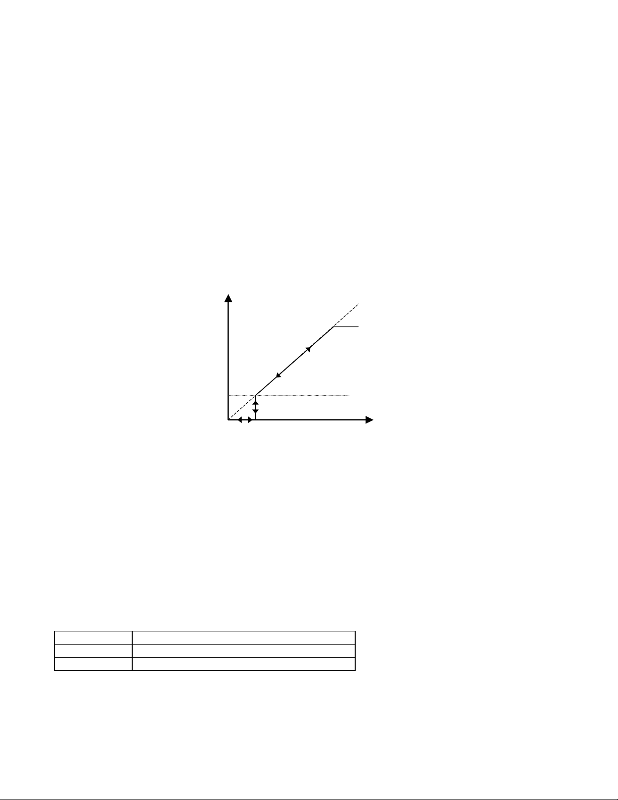
b5-15 Sleep Function Start Level
Sleep Level
Output
Speed Command
Upper Limit
d2-01
Output
Speed Command
b5-15
Setting Range: 0.0 to 200.0 Hz
Factory Default: 0.0 Hz
b5-16 Sleep Delay Time
Setting Range: 0.0 to 25.5 Seconds
Factory Default: 0.0 Seconds
The Sleep Function can be programmed to prevent running the Drive when the PI loop output or the speed command is so low
that no usable work is being done and/or equipment damage may result. The Sleep Function can be Enabled by entering a
value in parameter b5-15. If the Drive’s output drops below the level set by the Sleep Function Start Level (b5-15) and
remains there at least as long as the delay time determined by the Sleep Delay Time (b5-16), then the Drive’s internal Run
command drops out and the Drive output ceases. Though the Drive’s output has ceased, all other Drive functions continue.
Once the Drive’s theoretical output returns to a level above the Sleep Function Start Level (b5-15) and remains above that
level for at least the Sleep Delay Time (b5-16), the internal Run command returns and the Drive output begins again. The b516 Delay Time prevents oscillation about the sleep level.
Note: The sleep function can be used even if the PI function is disabled (b5-01 = “0: Disabled”).
Fig 5.18 Sleep Function Response
b5-17 PI Accel/Decel Time
Setting Range: 0.0 to 25.5 Seconds
Factory Default: 0.0 Seconds
This is a soft start function that is applied to the PI setpoint analog input. Instead of having nearly instantaneous changes in
signal levels, there is a programmed ramp applied to level changes. When changing setpoints the error can be limited by
gradually ramping the setpoint through the use of parameter b5-17.
b5-18 PI Setpoint Selection
Setting Description
0Disabled (factory default)
1Enabled
Programming 5 - 20
Page 95

In order to use parameter b5-19 as the PI Setpoint, set parameter b5-18= “1: Enabled”. If b5-18= “0: Disabled” the PI Setpoint
will either be:
• Modbus Register 06H (If Register 0FH bit 1 is high)
• The active speed command (i.e. Determined by the setting of b1-01). See Table 1 “Setpoint Options”
b5-19 PI Setpoint Value
Setting Range: (dependant on parameter b5-20)
B5-19 Setting Range Example:
b5-20 Setting b5-19 “Setting Range”
0 0 - 60.00
1 0.00 - 100.00
2 0 - 3600
4 0 - 1800
6 0 - 1200
Factory Default: 0.00
Parameter b5-19 is for a PI Setpoint value. When b5-18= “1: Enabled”, the value of b5-19 will take precedent over any other PI
setpoint unless the Drive is set up for Differential Feedback, in which case, b5-18 and b5-19 have no affect on the PI
function.
Displayed units are determined by b5-31, regardless of b5-20 setting. This does not affect the value programmed into the drive.
Example: if b5-20 = 1, b5-31 = 0, then b5-19 will be displayed in “WC: Inches of Water Column The value set in b5-19 will be
in percent feedback.
b5-20 PI Setpoint Display Scaling
Setting Range: 0 to 39999 <3020>
Factory Default: 1
Setting U1-24 and U1-38 Display Increments
00.01 Hz
10.00%
2-39 (enter # of
motor poles)
40 through
39999
RPM
Engineering Units
The PI Setpoint Display Scaling value (b5-20) is a scaling factor that is applied to the monitor display for both the PI Setpoint
(U1-38) and the PI Feedback (U1-24) and (b5-19) PI Setpoint. Display text for the units is set by b5-31 PI Unit Selection.
If the monitors seem more natural in terms of percentage, set b5-20= 1. If the monitors are easier to work with when displaying
the equivalent synchronous RPM, set b5-20= [the number of motor poles].
If another engineered unit, such a fpm or cfm, is desired, set b5-20= xxxxx where
X X X X X
Digit 5 Digit 4 Digit 3 Digit 2 Digit 1
Digits 1 through 4 set the desired number to be displayed at 100% feedback.
Digit 5 determines the number of decimal places.
If Digit 5 = 0 number format is XXXX
If Digit 5 = 1 number format is XXX.X
If Digit 5 = 2 number format is XX.XX
If Digit 5 = 3 number format is X.XXX
Programming 5 - 21
Page 96

For example:
If b5-20= 10425 then at 100% setpoint/feedback the digital operator would display 42.5 for monitor U1-38 or U1-24.
b5-21 Sleep Source
Setting Description
0 SFS Input (Output of PI block)
1 PI Setpoint (factory default)
2 Snooze
Parameter b5-21 selects the sleep function characteristic action:
When b5-21= “0: SFS Input” the sleep function start level (b5-15) is compared to the Drive’s output (Speed Command after PI
block). This is the setting that should be used for open loop or closed loop control.
It is also possible to have the sleep function start level (b5-15) compared to the Drive input or setpoint. For this special
application set b5-21= “1: PI Setpoint”.
When b5-21= “2: Snooze” a variation of the sleep function called “Snooze” is enabled, see parameter b5-22 to b5-27.
IMPORTANT
The sleep function can be used even if the PI function is disabled (b5-01= “0: Disabled”).
b5-22 PI Snooze Level
Setting Range: 0 to 100%
Factory Default: 0%
b5-23 PI Snooze Delay Time
Setting Range: 0 to 3600 Seconds
Factory Default: 0 Seconds
b5-24 PI Snooze Deactivation Level
Setting Range: 0 to 100%
Factory Default: 0%
The Snooze Function is a variation on the Sleep Function. The Snooze function must be selected by setting parameter
b5-21= “2: Snooze”. Once the Snooze Function is selected, the Drive monitors the output frequency. If the output frequency
drops below the PI Snooze Level (b5-22), and stays below that level for at least the PI Snooze Delay Time (b5-23), the Drive
output shuts off. This is different from the Sleep Function because it is the feedback that must drop below the PI Snooze
Deactivation Level (b5-24) before normal Drive output will begin again. See Fig 5.19 on next page.
b5-25 PI Setpoint Boost Setting
Setting Range: 0 to 100%
Factory Default: 0%
Programming 5 - 22
Page 97

Just before the Snooze Function is activated, the PI Setpoint can be temporarily increased to create an overshoot of the
PI Feedback
PI Setpoint
PI Output
Snooze
Function
t
b5-22
b5-23
b5-23
Either PI
Feedback
value or the
maximum boost
b5-24
ON
OFF OFF
PI Output
PI Setpoint
PI Feedback
Snooze
Function
TIME
b5-26
Either PI Feedback
reaches the new
boosted setpoint value
or the maximum boost
time b5-26 is reached.
intended PI Setpoint. The temporary boost is determined by the PI Setpoint Boost Setting (b5-25). Once the temporary boost
level is reached (or the PI Maximum Boost Time (b5-26) is exceeded), the Drive output shuts off (snoozes) and the intended PI
Setpoint returns. From this point on, the Snooze Function operates normally and the Drive output returns when the feedback
level drops below b5-24. See Fig 5.19 below.
b5-26 PI Maximum Boost Time
Setting Range: 0 to 3600 Seconds
Factory Default: 0 Seconds
Associated with the Snooze Function. In cases where the temporary PI Setpoint (intended PI setpoint + PI Setpoint Boost)
cannot be reached within the PI Maximum Boost Time (b5-26), the Setpoint Boost is interrupted and the Drive output is
turned off.
t
t
reaches the new
boosted setpoint
Fig 5.19 Snooze Function Operation
b5-27 PI Snooze Feedback Level
Setting Range: 0 to 100%
Factory Default: 60%
This is a second method of initiating the Snooze Function. If the PI feedback level exceeds the PI Snooze Feedback Level
(b5-27), then the Drive output shuts off. Once the PI feedback drops below the PI Snooze Deactivation Level (b5-24) then
normal Drive and PI operation return. Snooze activates if both b5-22 and b5-27 conditions are met. There is no time delay for
wake-up.
Programming 5 - 23
Page 98

b5-28 PI Feedback Square Root Function Activation
Setting Description
0 Disabled (factory default)
1Enabled
If b5-28= “1: Enabled”, the square root of the PI feedback is compared to the PI Setpoint in order to determine appropriate
Drive output to properly regulate the system. This is helpful in cases where the measured feedback is pressure but the PI loop
needs to regulate flow.
b5-29 PI Square Root Gain
Setting Range: 0.00 to 2.00
Factory Default: 1.00
A multiplier applied to the square root of the feedback.
b5-30 PI Output Square Root Monitor Selection
Setting Description
0 Disabled (factory default)
1Enabled
If the PI Function is regulating the flow of a closed loop system by using a pressure feedback, it may be convenient to view the
square root of the PI output using monitor U1-37.
b5-31 PI Unit Selection
Sets units for b5-19, U1-24 and U1-38.
Setting Description
0 WC: InchOfWater (factory default)
1 PSI: lb/SqrInch
2 GPM: Gallons/Min
3 F: DegFahrenheit
4 CFM: Cubic ft/Min
5CMH: Cubic M/Hr
6 LPH: Liters/Hr
7 LPS: Liters/Sec
8Bar: Bar
9Pa: Pascals
10 C: DegCelsius
11 Mtr: Meters
Parameter adjusts the units seen on the monitors U1-24 and U1-38. This parameter does not adjust the actual setpoint or the
setpoints scaling.
Programming 5 - 24
Page 99

b8 Energy Savings
The energy savings function improves overall system operating efficiency by operating the motor at its highest efficiency. This
is accomplished by continuously monitoring the motor load and adjusting the motor terminal voltage so that the motor always
operates near its rated slip frequency. A motor is most efficient when operating near rated slip conditions.
b8-01 Energy Savings Selection
Setting Description
0 Disabled (factory default)
1Enabled
When the Energy Savings function is enabled (b8-01= “1: Enabled”), the Drive reduces the output voltage to the motor below
the voltage value specified by the programmed V/f pattern whenever the motor load is light. Since torque is reduced during
this voltage reduction, the voltage has to return to normal levels when the load returns. The energy savings is realized through
improved motor efficiency. The reduced output voltage causes increased rotor slipping even with a light load. A motor is most
efficient when operating fully loaded (i.e. operating at rated slip).
b8-04 Energy Saving Coefficient Value
Setting Range: 0.0 to 655.0
Factory Default: Model Dependent
Parameter b8-04 is used in maximizing motor efficiency. The factory setting will be Drive capacity dependant but can be
adjusted in small amounts while viewing the kW monitor (U1-08) and running the Drive to minimize the output kW. A larger
value typically results in less voltage to the motor and less energy consumption. Too large a value will cause the motor to stall.
b8-05 Power Detection Filter Time
Setting Range: 0 to 2000 mS
Factory Default: 20 mS
The Energy Saving function will search out the lowest output voltage in order to achieve minimum output power usage.
Parameter b8-05 determines how often the output power (kW) is measured and the output voltage is adjusted.
b8-06 Search Operation Voltage Limit
Setting Range: 0 to 100%
Factory Default: 0%
Once Energy Savings is enabled and the optimal energy saving coefficient value has been set, the programmer can have the
Drive further search out the proper voltage to achieve the lowest output power by making minute changes to the output voltage
and measuring the output power every b8-05 ms. Parameter b8-06 sets limits to the range over which the voltage will be
adjusted in order to minimize the power output. Settings too large a value may allow the motor to stall if the load is applied
abruptly.
If b8-06= 0, then the optimum voltage search operation is disabled (but not Energy Savings itself).
Programming 5 - 25
Page 100

C1 Accel/Decel
C1-01 Acceleration Time 1
C1-02 Deceleration Time 1
C1-03 Acceleration Time 2
C1-04 Deceleration Time 2
Setting Range: 0.0 to 6000.0 Seconds
Factory Default: 30.0 Seconds
C1-01 (Acceleration Time 1) sets the time to accelerate from zero to maximum speed (E1-04). C1-02 (Deceleration Time 1)
sets the time to decelerate from maximum speed to zero. C1-01 and C1-02 are the factory default active accel/decel “pair”.
Another accel/decel pair (C1-03 and C1-04) exists that can be activated by a multi-function digital input (H1-0x= 7), or
specified by a switch over frequency as programmed in parameter C1-11.
Note: If fan applications employing duct high pressure safety limit switches, it may be necessary to further adjust the
deceleration time to avoid high pressure limit trips due to damper closure as the system is shut down. (An alternate solution in
this situation is to set parameter b1-03 to “Coast to Stop”).
C1-09 Fast Stop Time
Setting Range: 0.0 to 6000.0 Seconds
Factory Default: 10.0 Seconds
A special deceleration parameter is available for use with emergency or fault operations. Parameter C1-09 will set a
special deceleration that can be operated by closing a digital input configured as H1-0x= 15 or H1-0x= 17. A digital input
configured as H1-0x= 15 will look for a switch closure before initiating the Fast Stop operation. A digital input configured as
H1-0x= 17 will look for the switch opening before initiating the Fast Stop operation.
Unlike a standard deceleration time, once the Fast Stop operation is initiated even momentarily, the Drive cannot be
re-operated until the deceleration is complete, the Fast Stop input is cleared, and the Run command is cycled.
Programming 5 - 26
 Loading...