

Page 1

DX200 OPTIONS
1/54
INSTRUCTIONS
FOR ARC SENSOR COMARC FUNCTION
Upon receipt of the product and prior to initial operation, read these instructions thoroughly, and retain
for future reference.
MOTOMAN INSTRU CTIONS
MOTOMAN-- INSTRUCTIONS
DX200 INSTRUCTIONS
DX200 OPERA TOR’S MANUAL
DX200 MAINTENANCE MANUAL
The DX200 Operator’s manual above corresponds to specific usage.
Be sure to use the appropriate manual.
Part Number: 165557-1CD
Revision: 0
MANUAL NO.
HW1482187
0
Page 2

Arc Sensor Comarc
MANDATORY
CAUTION
2/54
165557-1CD
• This manual explains the arc sensor COMARC function of the
DX200 system and general operations. Read this manual carefully
and be sure to understand its contents before handling the DX200.
• General items related to safety are listed in Chapter 1: Safety of the
DX200 Instructions. To ensure correct and safe operation, carefully
read the DX200 Instructions before reading this manual.
• Some drawings in this manual are shown with the protective covers
or shields remov ed for clarity. Be sure all covers and shields are
replaced before operating this product.
• The drawings and photos in this manual are representative
examples and differences may exist between them and the
delivered product.
• YASKAWA may modify this model without notice when necessary
due to product improvements, modifications, or changes in
specifications.
• If such modification is made, the manual number will also be
revised.
• If your copy of the manual is damaged or lost, contact a YASKAWA
representative to order a new copy. The representatives are listed
on the back cover. Be sure to tell the representative the manual
number listed on the front cover.
• YASKA WA is not responsible for incidents arising from unauthorized
modification of its products. Unauthorized modification voids your
product's warranty.
ii
HW1482187
Page 3

165557-1CD
WARNING
CAUTION
MANDATORY
PROHIBITED
NOTE
3/54
Arc Sensor Comarc
Notes for Safe Operation
Read this manual carefully before installation, operation, maintenance, or
inspection of the DX200.
In this manual, the Notes for Safe Operation are classified as
“WARNING”, “CAUTION”, “MANDATORY”, or “PROHIBITED”.
Indicates a potentially hazardous
situation which, if not avoided, could
result in death or serious injury to
personnel.
Indicates a potentially hazardous
situation which, if not avoided, could
result in minor or moderate injury to
personnel and damage to equipment.
It may also be used to alert against
unsafe practices.
Always be sure to follow explicitly the
items listed under this heading.
Must never be performed.
Even items described as “CAUTION” may result in a serious accident in
some situations.
At any rate, be sure to follow these important items
To ensure safe and efficient operation at all times, be sure to
follow all instructions, even if not designated as "CAUTION"
and "WARNING".
iii
HW1482187
Page 4
Arc Sensor Comarc
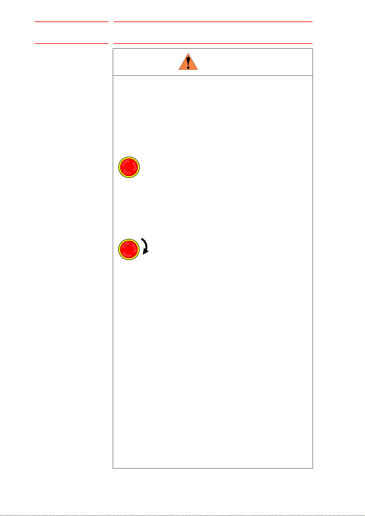
WARNING
TURN
4/54
165557-1CD
• Before operating the manipulator, check that servo power is turned
OFF pressing the emergency stop buttons on the front door of the
DX200 and the programming pendant.
When the servo power is turned OFF, the SERVO ON LED on the
programming pendant is turned OFF.
Injury or damage to machinery may result if the emergency stop circuit
cannot stop the manipulator during an emergency. The manipulator
should not be used if the emergency stop buttons do not function.
Figure 1: Emergency Stop Button
• Once the emergency stop button is released, clear the cell of all
items which could interfere with the operation of the manipulator.
Then turn the servo power ON.
Injury may r esult from unintentional or u nexpected manipulator motion.
Figure 2: Release of Emergency Stop
• Observe the following precautions when performing teaching
operations within the P-point maximum envelope of the
manipulator:
– View the manipulator from the front whenever possible.
– Always follow the predetermined operating procedure.
– Keep in mind the emergency response measures against the
manipulator’s unexpected motion toward you.
– Ensure that you have a safe place to retreat in case of
emergency.
Improper or unintended manipulator operation may result in injury.
• Confirm that no person is present in the P-point maximum envelope
of the manipulator and that you are in a safe location before:
– Turning ON the power for the DX200.
– Moving the manipulator with the programming pendant.
– Running the system in the check mode.
– Performing automatic operatio ns .
• Injury may result if anyone enters the P-point maximum envelope of
the manipulator during operation. Always press an emergency stop
button immediately if there is a problem.
The emergency stop buttons are located on the right of front door of
the DX200 and the programming pendant.
iv
HW1482187
Page 5

165557-1CD
CAUTION
5/54
Arc Sensor Comarc
• Perform the following inspection procedures prior to conducting
manipulator teaching. If problems are found, repair them
immediately, and be sure that all other necessary processing has
been performed.
– Check for problems in manipulator movement.
– Check for damage to insulation and sheath ing of external wires.
• Always return the programming pendant to the hook on the cabinet
of the DX200 after use.
The programming pendant can be damaged if it is left in the
manipulator's work area, on the floor, or near fixtures.
• Read and understand the Explanation of Warning Labels in the
DX200 Instructions before operating the manipulator.
Definition of Terms Used Often in This Manual
The MOTOMAN is the YASKAWA industrial robot product.
The MOTOMAN usually consists of the manipulator, the controller, the
programming penda nt, and su pply cab le s.
In this manual, the equipment is designated as follows.
Equipment Manual Designation
DX200 controller DX200
DX200 programming pendant Programming pendant
Cable between the ma nipulator and th e
controller
Manipulator cable
v
HW1482187
Page 6

Arc Sensor Comarc
6/54
Descriptions of the programming pendant keys, buttons, and displays are
shown as follows:
Equipment Manual Designation
Programming
Pendant
Character Keys
/Symbol Keys
Axis Keys
/Numeric Keys
Keys pressed
simultaneously
Displays The menu displayed in the programming
The keys which have characters or its
symbol printed on them are denote d with [ ].
ex. [ENTER]
[Axis Key] and [Numeric Key] are generic
names for the keys for axis operation and
number input.
When two keys are to be pressed
simultaneously, the keys are shown with a
“+” sign between them ,
ex. [SHIFT]+[COORD]
pendant is denoted with { }.
ex. {JOB}
Description of the Operation Procedure
165557-1CD
In the explanation of the operation procedure, the expression "Select • • • "
means that the cursor is moved to the object item and the SELECT key is
pressed, or that the item is directly selected by touching the screen.
Registered Trademark
In this manual, names of companies, corporations, or products are
trademarks, registered trademarks, or brand names for each company or
corporation. The indications of (R) and
TM
are omitted.
vi
HW1482187
Page 7

165557-1CD
7/54
Arc Sensor Comarc
1 Installation....................................................................................................................................... 1-1
1.1 Starting Point Detecting Unit..............................................................................................1-2
1.2 Current Detecting Unit ....................................................................................................... 1-3
2 DX200 Wiring.................................................................................................................................. 2-1
2.1 Connection Diagnosis........................................................................................................2-4
3 Arc Sensor Function ....................................................................................................................... 3-1
3.1 Basic Understanding of the Arc Sensor............................................................................. 3-1
3.1.1 Left and Right Path Correction............................................................................. 3-1
3.1.2 Up and Down Path Correction..............................................................................3-2
3.1.3 Applicable Range of the Arc Sensor..................................................................... 3-2
3.2 Main Operations for the Arc Sensor Function.................................................................... 3-3
Table of Contents
3.2.1 Job Preparation for Welding and Adjustment of Welding Conditions................... 3-3
3.2.1.1 Registration of Arc Sensing Instructions .................................................3-4
3.3 Arc Sensor Function and Weaving Condition.................................................................... 3-5
3.3.1 Path Correction Direction and Weaving Basis Coordinate System...................... 3-5
3.3.2 Cases that Require the Registration of Reference Points....................................3-7
4 Registration of Instructions ............................................................................................................. 4-1
4.1 COMARCON (Sensing Start Instruction)...........................................................................4-1
4.2 COMARCOF (Sensing End Instruction) ............................................................................4-4
4.3 COMARCSET (Sensing Condition Change)...................................................................... 4-5
4.4 REFP (Reference Point Registration)................................................................................ 4-7
5 Phase Compensation Value ...........................................................................................................5-1
5.1 Job Preparation for Measurement of Phase Compensation Value....................................5-1
5.2 Measurement and Registration of a Phase Compensation Value.....................................5-3
6 Measurement and Registration of Sensing Conditions................................................................... 6-1
6.1 Job for Measuring Sensing Conditions..............................................................................6-1
6.2 Measurement of Sensing Conditions................................................................................. 6-3
6.3 Registration of Sensing Conditions.................................................................................... 6-4
6.4 Adjustment of Sensing Conditions..................................................................................... 6-5
6.5 Results of Arc Sensing ......................................................................................................6-6
vii
HW1482187
Page 8

165557-1CD
8/54
Arc Sensor Comarc
7 COMARC Condition File .................................................................................................................7-1
7.1 COMARC Condition File....................................................................................................7-1
7.2 File Operation ....................................................................................................................7-3
7.2.1 Display of a File ....................................................................................................7-3
7.2.2 Editing of a File.....................................................................................................7-3
7.2.2.1 Editing of “CORRECTION SELECT” and “CONDITION” ........................7-3
7.2.2.2 Editing of Other Items..............................................................................7-3
7.2.3 Initialization of the File..........................................................................................7-4
8 Modification of the Settings in COMARC Function .........................................................................8-1
9 Instruction List.................................................................................................................................9-1
10 Parameter List.............................................................................................................................10-1
Table of C ontents
11 Alarm Message List.....................................................................................................................11-1
viii
HW1482187
Page 9

165557-1CD
WARNING
9/54
Arc Sensor Comarc
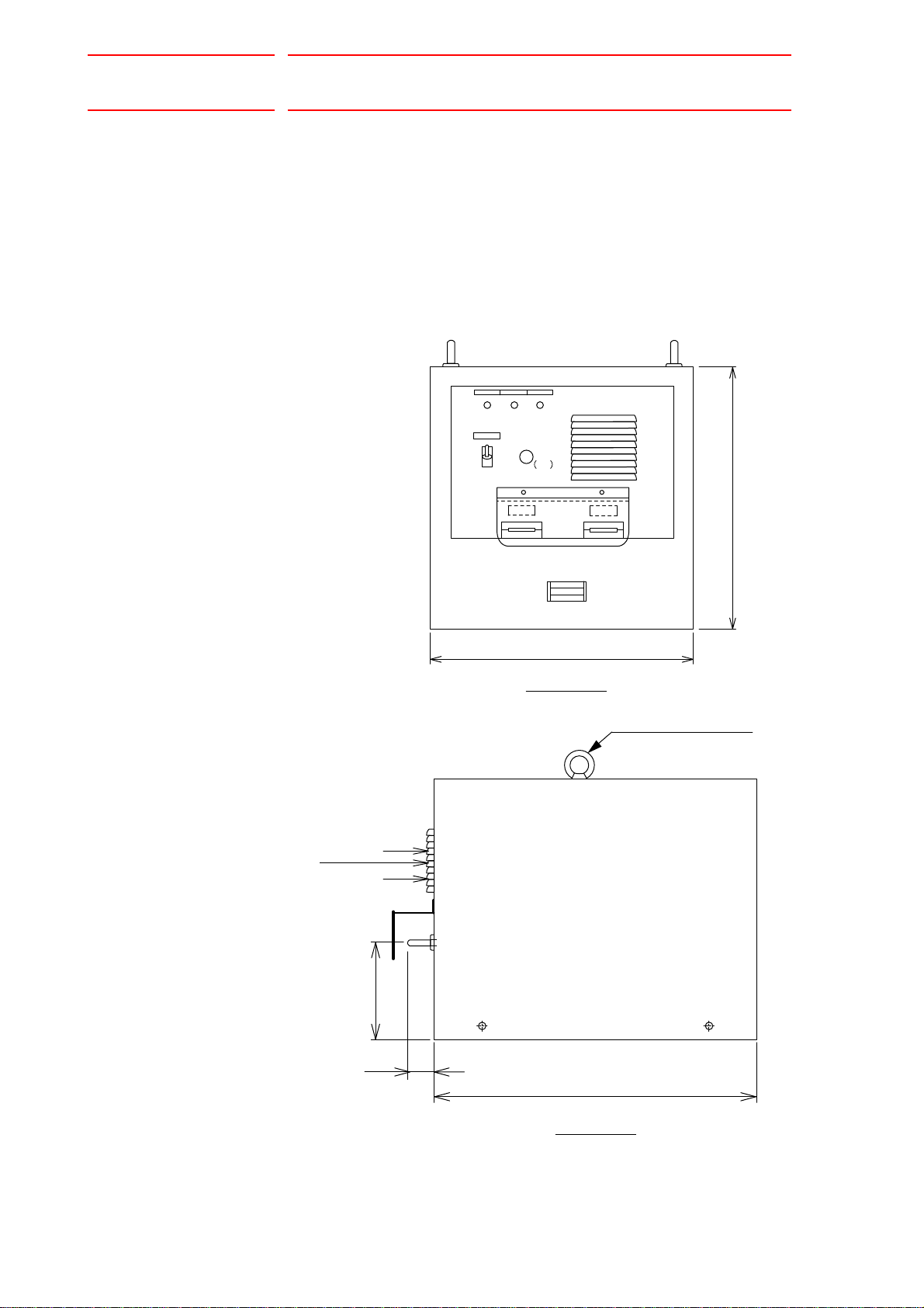
1 Installation
1 Installation
• Since detected voltage (200 V), welding current, and welding
voltage are applied to the starting point detecting unit, install the unit
securely so that it does not fall.
Failure to observe this warning may result in an electric shock or
damage to the unit.
For installation methods of a starting point detecting unit and a current
detecting unit, refer to Fig.1-1 Installation of Starting Point Detecting Unit
and Fig.1-2 Installation of Current Detecting Unit.
The starting point detecting unit should be installed outside of the
manipulator interference area.
1-1
HW1482187
Page 10
Arc Sensor Comarc
400
400
345
1NL 1LED 1PEI
3
1SW
ON
OFF
1FU
1A
2
1
Air vent
Front View
Eyebolt M8 (2 eyebolts)
500
(38)
150
Air vent
Side View
Units: mm
10/54
165557-1CD
1 Installation
1.1 Starting Point Detecting Unit
1.1 Starting Point Detecting Unit
The starting point detecting unit should be installed on the side of the
welder.
When installing the unit on a welder or other devices, use a fixture to fix
the unit with the mounting holes located on both sides of the unit in order
to prevent the unit from falling.
Fig. 1-1: Installation of Starting Point Detecting Unit
1-2
HW1482187
Page 11
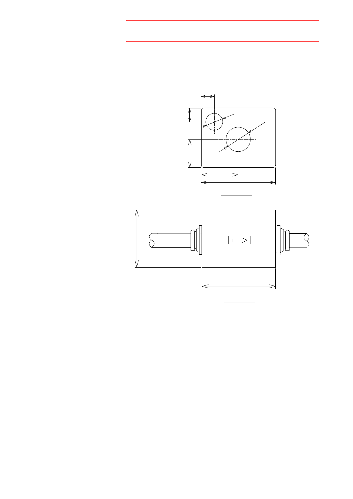
165557-1CD
11/54
Arc Sensor Comarc
1 Installation
1.2 Current Detecting Unit
1.2 Current Detecting Unit
Fig. 1-2: Installation of Current Detecting Unit
18
18
80
18
Ǿ21
Ǿ33.5
38
50
100
Front View
100
Units: mm
Side View
1-3
HW1482187
Page 12

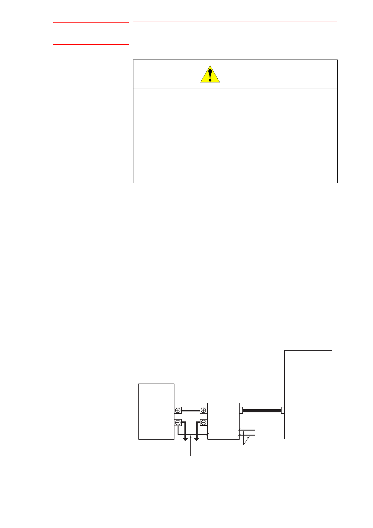
Arc Sensor Comarc
WARNING
12/54
2 DX200 Wiring
165557-1CD
2 DX200 Wiring
• Before connecting the inter-unit cables and the welding cables, be
sure to turn OFF the power supply to the DX200 and the welder.
Failure to observe this warning may result in an electric shock.
• Special attention should be paid during starting point detection,
since 200 VDC is applied across the wire and the workpiece
(welding jig).
Failure to observe this warning may result in an electric shock.
• Do not place any object directly on the cable of the starting point
detecting unit.
Failure to observe this warning may result in an injury or damage
caused by the disconnection of the cable.
• Attach the cable of the starting point detecting unit for the wire
feeder with the wire stand, to protect it from robot movement.
If interference between the cable and the peripheral devices cannot
be avoided, cover the cable with a rubber plate or spiral tube, etc.
Failure to observe this warning may result in an electric shock caused
by damage to the cable, or an injury or damage caused by malfunction.
• Do not lay the cable of the starting point detecting unit directly on
the floor, but install them in a pit or duct, or attach the cable with a
protective co ve r.
Failure to observe this warning may result in an injury or damage to the
cable.
• Since a high current flows through the welding cable, separate it
from the cables of the control circuit system. If the cables cannot be
separated, take preventative measures such as using metallic ducts
or tubes on the cables of the control circuit system.
2-1
HW1482187
Page 13
165557-1CD
CAUTION
1CN
SE1
SE2
DX200
E
Welder
Welding cable
Starting point
detecting unit
Ground cable
To the workpiece To the wire feeder
Cable for welding voltage detection
To the torch
To the welder
Inter-unit cable
YCP02 board
13/54
Arc Sensor Comarc
2 DX200 Wiring
• Insert the inter-unit cable on the starting point detecting unit side,
firmly to the connector, and fix it securely by tightening the coupling
nut.
• Fix the other cables connected to the terminal stand securely by
tightening the terminal screws.
Failure to observe these cautions may result in an electric shock, an
injury, or damage caused by malfunctioning.
• After connected, be sure to reinstall the terminal covers of starting
point detecting unit and welder.
Failure to observe this caution may result in an electric shock.
Wire the unit in the following manner, referring to Fig.2-1 Configuration
Diagram of Starting Point Detecting Unit and Fig.2-2 Configuration
Diagram of Current Detecting Unit.
Starting Point Detecting U nit
1. Connect the starting point detecting unit to the DX200.
2. Connect the plus terminal of the starting point detecting unit to the plus
terminal of the welder.
3. Connect the minus terminal of the starting point detecting unit to the
torch power supply unit on the wire feeder.
4. Connect the front terminal of the stand of the starting point detecting
unit to the welding voltage detecting terminal on the wire feeder in the
case of a floor-standing type, and to the terminal stand in the welder in
the case of a welder-side hung type, respectively.
Fig. 2-1: Configuration Diagram of Starting Point Detecting Unit
2-2
HW1482187
Page 14

Arc Sensor Comarc
14/54
165557-1CD
2 DX200 Wiring
Current Detecting Unit
1. Connect the connection cable of current detecting unit to the DX200.
2. Connect the plus cable of the current detecting unit to the + terminal of
the welder.
Connect the other cable to the welding cable from the torch power
supply unit on the wire feeder, and tape it with an insulating tape.
Fig. 2-2: Configuration Diagram of Current Detecting Unit
DX200
Welder
Current detecting unit
YCP02 board
To the workpiece To the wire feeder
2-3
HW1482187
Page 15

165557-1CD
NOTE
15/54
Arc Sensor Comarc
2 DX200 Wiring
2.1 Connection Diagnosis
2.1 Connection Diagnosis
To confirm a connection, perform a diagnosis of the input status to the
YCP02 board.
(The YCP02 board is a board for the COMARC.)
Use the following procedure to call the YCP 02 I/O status display.
1. Select {IN/OUT} from the main menu.
2. Select {YCP02 I/O}.
– The YCP02 I/O STATUS window appears.
– In this display, confirm the values read-by the YCP02 board’s A/D
converter and the general I/O status.
– Eight channels are provided for the A/D converter.
– Four points for input and output respectively are provided for general
I/O.
– Use the YCP02 I/O STATUS window for the following purposes;
• Check whether the A/D converter is correctly operating.
• Check whether the cables for the current detecting unit are correctly connected.
For an incorrect
connection
For normal status When welding is performed by
• The YCP02 I/O STATUS window can be called only in
"MANAGEMENT MODE".
• When the icon {YCP02 I/O} does not appear, switch the
security mode to "MANAGEMENT MODE".
When welding is performed, the A/D
data shows a negative value (-).
executing the normal ARCON/ARCOF,
the A/D data show a positive value (+).
(Execute a job without using
COMARCON/COMARCOF.)
2-4
HW1482187
Page 16

Arc Sensor Comarc
Welding current: = , (When the distance
between the tip and the base metal is the same on
both sides.)
1 2
1 2
Welding current > (shifted to the left) Welding current < (shifted to the right)
Direction of path
correction
Direction of path
correction
1
21 2
1 2 1 2
16/54
3 Arc Sensor Function
3.1 Basic Understanding of the Arc Sensor
3 Arc Sensor Function
3.1 Basic Understanding of the Arc Sensor
For welding with a power supply that has constant voltage characteristics,
the welding current fluctuates as the distance L changes as shown below.
Distance L is the distance between the tip and the base metal. The arc
sensor function uses these characteristics.
Consumable
electrode (wire)
Arc
165557-1CD
Welding current
High Low
Tip
L
Base
metal
3.1.1 Left and Right Path Corre ction
During welding with the torch weaving from side to side, an equal amount
welding current flows on points and if the distance L is the same on
both sides (points and ) due to the aforementioned characteristics.
If the distances L are different at points and , different currents flow at
these two points as shown below.
The arc sensor checks the welding currents at points and and
corrects the path to equalize the values.
3-1
HW1482187
Page 17
165557-1CD
Up and down path
correction
Up and down path
correction
NOTE
SUPPLE-
MENT
17/54
Arc Sensor Comarc
3 Arc Sensor Function
3.1 Basic Understanding of the Arc Sensor
3.1.2 Up and Down Path Correction
During welding with the torch moving up and down, the arc sensor checks
the welding currents at any 2 points, an upper point and a lower point, and
corrects the path to equalize the values.
3.1.3 Applicable Range of the Arc Sensor
The applicable metal thickness and joint are as follows.
Metal thickness: 3.2 mm or more
Joint: T joint, Lap joint
Speed: 1 m/min or less
The arc sensor function can be used except that the droplet
transfer status is a spray transfer.
• The droplet transfer means that the welded tip of wire
(droplet) transfers to the base metal.
• For the status of droplet transfer, there are dip transfer,
spray transfer, and etc.
3-2
HW1482187
Page 18

Arc Sensor Comarc
Prepare a job for welding.
Set and adjust the welding
conditions.
18/54
165557-1CD
3 Arc Sensor Function
3.2 Main Operations for the Arc Sensor Function
3.2 Main Operations for the Arc Sensor Function
3.2.1 Job Preparation for Welding and Adjustment of Welding Conditions
Prepare a job for welding and adjust the welding conditions.
3-3
HW1482187
Page 19

165557-1CD
NOTE
Register a COMARCON/
COMARCOF instruction in
the arc sensing section.
19/54
Arc Sensor Comarc
3.2.1.1 Registration of Arc Sensing Instructions
3 Arc Sensor Function
3.2 Main Operations for the Arc Sensor Function
Register a COMARCON/COMARCOF instructions in the section where
arc sensing is to be performed.
Set the UP/DOWN correction condition (U/D) to the same values as the
value of the current setting in the ARCON instruction.
Set the LEFT/RIGHT co rrecti on con di tion to "0".
When adjustment of the targeted position is required after seeing the
results of the welding done with the arc sensor, adjust the UP/DOWN
correction conditions (U/D) or the LEFT/RIGHT correction conditions (L/
R).
For details on how to adjust the UP/DOWN and LEFT/RIGHT correction
conditions, refer to Section 6.4 “Adjustment of Sensing Conditions” on
page 6-5.
Depending on the welding current range to be used, the
current value set with ARCON instruction may differ from
the current value actually output from the welder.
In this case, measure the sensing conditions when
registering the COMARCON instruction.
For details on how to measure a sensing condition, refer to
Chapter 6 "Measurement and Registration of Sensing
Conditions" on page 6-1.
When an actual workpiece cannot be used to measure a
sensing condition, use a test pie ce .
Then, for the UP/DOWN and LEFT/RIGH T correc ti on
conditions ( U/D a n d L /R) for the COMARCON instruction in
the actual work job, enter the values based on those
measurements using the numeric keys.
3-4
HW1482187
Page 20

Arc Sensor Comarc
SUPPLE-
MENT
NOTE
Horizontal direction
Weaving Basis Coordinate System
Advance direction
Wall direction
Wall direction
Z direction
Horizontal
direction
Approach point
20/54
165557-1CD
3 Arc Sensor Function
3.3 Arc Sensor Function and Weaving Condition
3.3 Arc Sensor Function and Weaving Condition
3.3.1 Path Correction Direction and Weaving Basis Coordinate System
As described in Section 3.1 “Basic Understanding of the Arc Sensor” on
page 3-1 , the path correcting direction and weaving action are closely
related.
Weaving is performed based on the following coordinate system. This
coordinate system is generated automatically when weaving is executed.
Wall Direction: Z direction of the robot axis
Horizontal Direction: The direction of approach point from the wall
Advance Direction: The direction that the torch moves from the weaving
start point to the end poin
t
The approach point is a point indicated by a step
immediately before the step where weaving starts.
Depending on the mouthing and shape of the workpiece, a
definition of the above coordinate system may not be
sufficient to generate a weaving pattern. In that case,
register the reference point REFP 1 or REFP 2.
For details, refer to Section 3.3.2 “Cases that Require the
Registration of Reference Points” on page 3-7
.
3-5
HW1482187
Page 21

165557-1CD
21/54
Arc Sensor Comarc
3 Arc Sensor Function
3.3 Arc Sensor Function and Weaving Condition
The weaving coordination and the path correcting direction are as follows.
Wall direction
Up and Down
Up and Down
Left and Right
Horizontal
direction
Wall direction
Left and Right
Horizontal
direction
Left and Right path correction is same as the amplitude direction of a
weaving, and Up and Down path correction is same as perpendicular
direction against the amplitude of a weaving.
3-6
HW1482187
Page 22

Arc Sensor Comarc
SUPPLE-
MENT
REFP1 REFP2
On the wall surface or
its expansion plane
On the right or left side of the wall
Horizontal
direction
Advance
direction
Wall direction
WallWall
REFP1REFP1REFP1
REFP1
REFP2
REFP2
Advance
direction
Wall direction
22/54
165557-1CD
3 Arc Sensor Function
3.3 Arc Sensor Function and Weaving Condition
3.3.2 Cases that Require the Registration of Reference Points
The registration of the reference point REFP1 or REFP2 is not usually
required. They are required only with a special workpiece condition, etc.
The REFP1, that defines the wall direction, is a point on the wall surface
or its expansion plane. The REFP2, which defines the horizontal
direction, is a point on the right or left side of the wall.
< Example 1 >
REFP1 is registered because the wall direction is not parallel to the Z
direction of the robot axis.
Also, register REFP1 when a robot is hanging from the ceiling. In such
case, the Z direction of the robot axis differs from wall direction.
For information on registering REFP, refer to Section 4.4
“REFP (Reference Point Registration)” on page 4-7.
Z direction
Wall direction
REFP1
0003
0004
0005
0006
0007
Example
MOVL V=120
REFP 1
WVON WEV#(1)
MOVL V=50
WVOF
3-7
HW1482187
Page 23

165557-1CD
A
23/54
Arc Sensor Comarc
3 Arc Sensor Function
3.3 Arc Sensor Function and Weaving Condition
< Example 2 >
REFP2 is registered because the approach point is on another side of
the wall.
Example
Wall
pproach point
REFP2
Approach point
0009 MOVJ VJ=25.00
0010
MOVL V=120
0011
REFP 2
0012
WVON WEV#(1)
0013
MOVL V=50
0014
WVOF
3-8
HW1482187
Page 24

Arc Sensor Comarc
24/54
4 Registration of Instructions
4.1 COMARCON (Sensing Start Instruction)
4 Registration of Instructions
4.1 COMARCON (Sensing Start Instruction)
The COMARCON instruction starts the arc sensing and weaving.
correction conditions (UP/DOWN correction condition, RIGHT/LEFT
correction condition), and the COMARC condition file No. specifications.
< > indicates numerical or alphabetical data.
COMARCON Function Starts arc sensing and weaving.
165557-1CD
Instructio
n items
Examples COMARCON AMP=2.0 FREQ=3.0 U/D=200 L/R=0.0
Settings Data input range Unit
Weaving conditions
AMP = <Weaving amplitude>
FREQ = <Weaving frequency>
ANGL=<Weaving angle>
WEV# (<Weaving file No.>)
DIR=<Weaving direction>
Correction conditions
U/D = <Correcting the up and down
path)
L/R = <Correcting the left and right
path>
COMARC condition file No.
CAF# (<COMARC condition file No.>) 1 to 128 -
COMARCON WEV#(1) U/D=200 L/R=0.0
COMARCON AMP=2.0 FREQ=3.0 U/D=200 L/R=0.0 CAF#(1)
COMARCON WEV#(1) U/D=200 L/R=0.0 CAF#(1)
1)
AMP: 0.1 to 99.9
FREQ: 0.1 to 5.0
ANGL: 0.0 to 180.0
1 to 255
0 or 1
U/D: 1 to 999
L/R: -255.0 to 255.0
0.1 mm
0.1 Hz
0.1 deg.
-
-
1 A
0.1 A
1 Two setting methods are available: setting by AMP and FREQ or setting by WEV#. When
weaving condition s are set by AMP and FRE Q, the weavin g mod e is “sin gle oscil latio n”. When
ANGL is set to UNUSED, weaving angle is set to 45 deg.
Do not use DIR normally. DIR specifies the weaving direction changing. DIR=0 equals to
UNUSED.
4-1
HW1482187
Page 25

165557-1CD
NOTE
25/54
Arc Sensor Comarc
4 Registration of Instructions
4.1 COMARCON (Sensing Start Instruction)
• Be sure to register the COMARCON instruction after the
ARCON instruction.
Register the COMARCON/COMARCOF instruction and
the ARCON/ARCOF instruction in the same job.
• For setting and adjusting sensor correction conditions,
refer to Chapter 6 "Measurement and Registration of
Sensing Conditions" on page 6-1.
• When a COMARC condition file is not specified for the
COMARCON instruction, perform sensing under the
following conditions in the COMARC condition file display.
• “CORRECTION SELECT” (direction of path correction):
U/D & L/R (all directions)
• “CONDITION” (operation after pass-over): NOT
MONITOR
For details on the COMARC condition file, refer to Chapter
7 "COMARC Condition File" on page 7-1.
1. Move the cursor to the address area.
2. Press [I NFORM LIST].
3. Select "SENSOR".
4. Select "COMARCON".
– The instruction appears with the previously registered additional
items in the input buffer line.
5. Press [SELECT], and set the conditions in the detail edit window.
(1) Move the cursor to the item to be set, and press [SELECT].
(2) Enter each condition using the numeric keys, and then press
[ENTER].
4-2
HW1482187
Page 26

Arc Sensor Comarc
26/54
165557-1CD
4 Registration of Instructions
4.1 COMARCON (Sensing Start Instruction)
– The following two methods are available to set weaving conditions.
• When a weaving condition is set by additional items
• When a weaving condition is specified by the file
6. Press [ENTER] twice.
– Press [ENTER] in the detail edit window to display the setting details
in the input buffer line.
Press [ENTER] again to register the setting details in the job.
4-3
HW1482187
Page 27

165557-1CD
NOTE
27/54
Arc Sensor Comarc
4 Registration of Instructions
4.2 COMARCOF (Sensing End Instruction)
4.2 COMARCOF (Sensing End Instruction)
The COMARCOF instruction ends arc sensing and weaving.
COMARCOF Function End s arc sen si ng and weav in g.
Instruction
item
Example COMARCOF
Be sure to register the COMARCOF instruction before the
ARCOF instruction.
Register the COMARCON/COMARCOF instruction and the
ARCON/ARCOF instruction in the same job.
1. Move the cursor to the address area.
2. Press [I NFORM LIST].
-
3. Select "SENSOR".
4. Select "COMARCOF".
– The instruction appears in the input buffer line.
5. Press [ENTER].
4-4
HW1482187
Page 28

Arc Sensor Comarc
NO TE
28/54
165557-1CD
4 Registration of Instructions
4.3 COMARCSET (Sensing Condition Change)
4.3 COMARCSET (Sensing Condition Change)
The COMARCSET instruction changes the arc sensing conditions and the
weaving conditions.
There are three types of settings for the COMARCSET instruction:
weaving conditions (weaving amplitude, weaving angle), sensor
correction conditions (UP/DOWN correction condition, RIGHT/LEFT
correction direction), and the COMARC condition file No. specifications.
<> indicates numerical or alphabetical data.
COMARCSET
1)
Function Changes the sensing conditions and the weaving condition.
Instruction
items
Examples COMARCSET AMP=2.5 U/D=210 L/R=0.0 CAF#(2)
Settings Data input range Unit
Weaving conditions
AMP = <Weaving amplitude>
ANGL=<Weaving angle>
Correction conditions
U/D = <correcting the up and down path>
L/R = <correcting the left and right path>
COMARC condition file No.
CAF# (<COMARC condition file No.>) 1 to 128 -
COMARCSET AMP=2.5
COMARCSET U/D=210
COMARCSET L/R=1.0
COMARCSET CAF#(2)
AMP: 0.1 to 99.9
ANGL: 0.0 to 180.0
U/D: 1 to 999
L/R: -255.0 to 255.0
1 For the COMARCSET instruction, only the items to be changed can be set.
• The conditions registered with the COMARCSET
instruction are validated when executing the move
instruction after the COMARCSET instruction.
0.1 mm
0.1 deg.
1 A
0.1 A
• For setting and adjusting sensor correction conditions,
refer to Chapter 6 "Measurement and Registration of
Sensing Conditions" on page 6-1.
• For details on the COMARC condition file, refer to Chapter
7 "COMARC Condition File" on page 7-1.
4-5
HW1482187
Page 29

165557-1CD
29/54
Arc Sensor Comarc
4 Registration of Instructions
4.3 COMARCSET (Sensing Condition Change)
1. Move the cursor to the address area.
2. Press [I NFORM LIST].
3. Select "SENSOR".
4. Select "COMARCSET".
– The instruction appears with the previously registered additional
items in the input buffer line.
5. Press [SELECT], and set the conditions in the detail edit window.
(1) Move the cursor to the item to be set, and press [SELECT].
(2) Enter each condition using the numeric keys, and then press
[ENTER].
6. Press [ENTER] twice.
4-6
HW1482187
Page 30

Arc Sensor Comarc
Place before where
reference point is to
be registered
Reference point
is registered.
30/54
165557-1CD
4 Registration of Instructions
4.4 REFP (Reference Point Registration)
4.4 REFP (Reference Point Registration)
Reference point instructions (REFP) set an auxiliary point such as a wall
point for weaving.
Reference points No.1 to 8 are assigned for each application. Follow the
procedure below to register reference point instructions.
1. Select {JOB} under the main menu.
2. Select {JOB}.
3. Move the cursor.
– Move the cursor to the line immediately before the position where
the reference point to be registered.
4. Squeeze the Enable switch.
– The servo power is turned ON.
5. Press the axis key.
– Use the axis key to move the manipulator to the position to be
registered as a reference point.
6. Press [REFP].
– The reference point instruction is displayed in the input buffer line.
7. Change the reference point number.
– Move the cursor to the reference point number, and press [SHIFT] +
the cursor key to change the reference point number.
– If you use the numeric keys to input the reference point number,
press [SELECT] when the cursor is on the reference point number
("Ref-point_no.=").
The data input line is displayed. Input number and press [ENTER].
8. Press [INSERT].
– The [INSERT] key lamp lights.
– When registering before the END instruction, [INSERT] is not
needed.
9. Press [ENTER].
– The REFP instruction is registe r ed.
4-7
HW1482187
Page 31

165557-1CD
A
31/54
Arc Sensor Comarc
5 Phase Compensation Value
5.1 Job Preparation for Measurement of Phase Compensation Value
5 Ph ase Compensation Value
As explained in Section 3.1 “Basic Understanding of the Arc Sensor” on
page 3-1, the arc sensing corrects the manipulator path by measuring the
welding current values at the peak and bottom of the waves of weaving
motion.
However, in the actual welding, a discrepancy between the weaving cycle
and the peak value of the current variation cycle is generated as shown in
the following figure.
The phase compensation value compensates for this discrepancy.
Since the phase compensation value differs depending on the welding
circumstances, measure and register a value for each welder.
Welding current peak value
Welding current wave form
Both ends of weaving motion
discrepancy between the weaving motion and the welding current peak value is generated.
5.1 Job Preparation for Meas ureme n t of Phas e
Compensa tion Value
Prepare a job to measure a phase compensation value.
Refer to the following job example to prepare a job for measurement of a
phase compensatio n val ue.
Table 5-1: Job Example for Measurement of Phase Compensation Value
NOP
MOVJ VJ=50.00
MOVJ VJ=50.00
ARCON AC=200 AVP=100
COMARCON AMP=2.0 FREQ=3.0 U/D=200 L/R=0.0
MOVL V=80
COMARCOF
ARCOF
MOVL V=800
MOVJ VJ=50.00
END
Weaving motion
5-1
HW1482187
Page 32

Arc Sensor Comarc
NO TE
32/54
165557-1CD
5 Phase Compensation Value
5.1 Job Preparation for Measurement of Phase Compensation Value
For measurement of a phase
compensation value, teach the
torch positions as if there is a top
plate. (Steps 2 and 3).
Step 4
Step 3
Step 2
Steps 1
and 5
• Execute a job for measurement of phase compensation
value under the same welding condition (current value,
voltage value, torch positions) as a job with an actual
workpiece.
• For the weaving conditions, measure the phase
compensation values for all the weaving frequencies used
in the actual welding.
• For measurement of a phase compensation va lue , teach
the torch positions as if there is a top plate. (Steps 2 and
3).
5-2
HW1482187
Page 33

165557-1CD
NO TE
33/54
Arc Sensor Comarc
5 Phase Compensation Value
5.2 Measurement and Registration of a Phase Compensation Value
5.2 Measurement and Registration of a Phase Compensation
Value
• Measuring and registering a phase compensation value is
only possible in “MANAGEMENT MODE”. Change the
security mode to “MANAGEMENT MODE”.
• The phase compensation value is registered in the
parameter SxE. To measure and register phase
compensation value, set the parameter SxE197 to “1” first,
then proceed the following operations.
• After the registration of phase compensation value, be
sure to reset the parameter SxE197 to “0”.
1. Select the job for measurement of a phase compensation value.
2. Select {U TILITY} in the JOB CONTENT window in pl ay mode.
3. Select {SETUP SPECIAL RUN} from the selection dialog box.
– The SPECIAL PLAY window appears.
4. Set the "COMARC MEASURE MODE" to "VALID".
(1) Move the cursor to "COMARC MEASURE MODE", and press
[SELECT] to set the mode to "VALID".
(2) The message "COMARC MEASURE MODE" appears in the mes-
sage line.
5. Execute the job.
6. Select {UTILITY} in t he teach mode.
5-3
HW1482187
Page 34

Arc Sensor Comarc
NO TE
34/54
165557-1CD
5 Phase Compensation Value
5.2 Measurement and Registration of a Phase Compensation Value
7. Select {COMARC COND. MODIFY}.
– The COMARC PHASE COMP window appears.
8. Select {PARAMETER} from the main menu.
9. Select {SxE}.
10.Display the parameter No. to be changed.
11. Register the measured value.
– Register the phase compensation value confirmed in the COMARC
PHASE COMP window appears.
• After measuring the phase compensation value, be sure to
reset the "COMARC MEASURE MODE" to “INVALID”.
• When the shielding gas is changed, measure and register
the phase compensation value.
If the type of shielding gas is different, the parameter No.
is different.
Measure and register phase compensation values for all the
frequencies used in the actual welding.
Depending on the frequency for which a phase
compensation value is measured, the values may be
registered in same parameter No.. In this case, register the
average value of several measured phase compensation
values.
<Example>
The phase compensation values for the weaving frequencies 4.0 Hz and 5.0 Hz are registered in SxE060.
In this case, the average value of the phase compensation values for the weaving frequencies 4.0 Hz and 5.0 Hz
is registered in SxE060.
5-4
HW1482187
Page 35

165557-1CD
1
6
3
2
4
5
1 to 6: Taught steps
35/54
Arc Sensor Comarc
6 Measurement and Registration of Sensing Conditions
6.1 Job for Measuring Sensing Conditions
6 M easurement and Registration of Sensing Cond itio ns
6.1 Job for Measuring Sensing Conditions
Play back the measuring job in the sensing condition measurement mode
to automatically measure the data of the sensing conditions (correction
conditions in the up/ down/left/right directions).
The following shows an example of a measuring job.
<Example>
Job for measuring sensing conditions
0000 NOP
0001 MOVJ VJ=50.00
0002 MOVJ VJ=50.00
0003 MOVJ VJ=30.00
0004 ARCON AC=200 AVP=100
0005 COMARCON AMP=2.0 FREQ=3.0 U/D=200 L/R=0.0
0006 MOVL V=80
0007 COMARCOF
0008 ARCOF
0009 MOVJ VJ=30.00
0010 MOVJ VJ=50.00
0011 END
Stand-by position
Welding star t posi tio n
Sensing starts
(measures a conditio n)
Welding end position
Sensing completed
Stand-by position
6-1
HW1482187
Page 36

Arc Sensor Comarc
NO TE
36/54
165557-1CD
6 Measurement and Registration of Sensing Conditions
6.1 Job for Measuring Sensing Conditions
Before measuring a condition, make sure that the
workpiece is not dislocated.
If the workpiece is dislocated, correct the dislocation or
correct the taught position for the measuring job.
Measure the sensing conditions in a single section within
the same job.
Do not set more than one sensing section in the same job.
<Wrong Setting Example>
MOVJ VJ=30.00
ARCON AC=200 AVP=100
COMARCON AMP=2.0 FREQ=3.0 U/D=200 L/R=0.0
MOVL V=80
COMARCOF
COMARCON AMP=2.0 FREQ=3.0 U/D=200 L/R=0.0
MOVL V=80
COMARCOF
ARCOF
MOVJ VJ=30.00
6-2
HW1482187
Page 37

165557-1CD
NO TE
37/54
Arc Sensor Comarc
6 Measurement and Registration of Sensing Conditions
6.2 Measurement of Sensing Conditions
6.2 Measurement of Sensing Conditions
1. Select {UTILITY} in the JOB CONTENT window in the play mode.
2. Select {SPECIAL PLAY} from the selection dialog box.
– The SPECIAL PLAY window appears.
3. Set "COMARC MEASURE MODE" to "VALID".
(1) Move the cursor to "COMARC MEASURE MODE", and press
[SELECT} to set the mode to "VALID".
(2) "COMARC MEASURE MODE" appears in the message line.
4. Execute the job.
Be sure to reset the “COMARC MEASURE MODE” to
"INVALID" after measuring the sensing conditions.
6-3
HW1482187
Page 38

Arc Sensor Comarc
38/54
165557-1CD
6 Measurement and Registration of Sensing Conditions
6.3 Registration of Sensing Conditions
6.3 Registration of Sensing Conditions
1. Select {UTILITY} in the JOB CONTENT window in the teach mode.
2. Select {COMARC COND. MODIFY}.
– The COMARC COND. MODIFY window appears.
3. Select "MODIFY COMARC COND" from the {DATA} selection box.
– The sensing conditions are registered in the job.
– When registration is complete, the JOB CONTENT window
reappears.
6-4
HW1482187
Page 39

165557-1CD
NO TE
39/54
Arc Sensor Comarc
6 Measurement and Registration of Sensing Conditions
6.4 Adjustment of Sensing Conditions
6.4 Adjustment of Sensing Conditions
1. Move the curso r t o th e inst ru ctio n ar ea of t h e COM ARC ON inst ru cti on
or the COMARCSET instr uct ion.
2. Press [SELECT] twice.
3. Select either "UP/DOWN" or "LEFT/RIGHT" in the DET AIL EDIT
window.
– Enter a value using the numeric keys.
The following is the relation between the settings of the
correction conditions and the correction direction.
To define the direction along the wall and horizontally, refer
to Section 3.3 “Arc Sensor Function and Weaving
Condition” on page 3-5.
• To lengthen a wire extension, decrease the UP/DOWN (U/
D) correction condition in units of 10 A.
• T o shorten a wire extension, increase the UP/DOWN (U/D)
correction condition in units of 10 A.
• To move the targeted position toward the wall, decrease
the LEFT/RIGHT (L/R) correction condition in units of 5 A.
• To move the targeted position toward the horizontal
direction, increase the LEFT/RIGHT (L/R) correction
condition in units of 5 A.
Wall
direction
LEFT
DOWN
UP
RIGHT
Horizontal
direction
6-5
HW1482187
Page 40

Arc Sensor Comarc
NO TE
40/54
165557-1CD
6 Measurement and Registration of Sensing Conditions
6.5 Results of Arc Sensing
6.5 Results of Arc Sensing
After arc sensing has been performed, the history of the correction
amount in each step can be viewed.
1. Select {ARC WELDING} from the main menu.
2. Select {COMARC CORRECT}.
– The correction amount in each step appears.
The CORRECTING LIST window only appears when
sensing has been performed.
Therefore, the icon “COMARC CORRECT” does not appear
when turning the power ON or before performing sensing.
6-6
HW1482187
Page 41

165557-1CD
41/54
Arc Sensor Comarc
7 COMARC Condition File
7.1 COMARC Condition File
7 COMARC Condition File
Set the following two items in the COMARC co nditi on file s.
• Direction of path correction by sensing
• Pass-over monitoring condition
7.1 COMARC Condition File
1
2
3
4
5
6
COND NO. (1 to 128)
Displays the file No.
CORRECTION SELECT (direction of path correction) (U/D & L/R,
U/D, L/R, NO CORRECTION)
Specifies the direction to be corrected. When “NO CORRECTION” is
selected, a correction by sensing is not performed.
U/D & /L/R Corrects the path in the up, down, left, and right directions.
L/R Corrects the path in the left and right directions
(the up and down directions are not co rrec ted) .
U/D Corrects the path in the up and down directions
(the left and right directions are not corrected).
CONDITION (operation after pass-over) (ALARM, TEACHING
POSITION, CORRECTION RETAIN, NOT MONITOR)
Specifies the operation to be done when a pass-over occurs.
ALARM An alarm occurs, and the manipulator stops.
Pass-over occurred,
and the manipulator
stops.
Pass-over
monitor value
Actual welding line
7-1
Taught line
: Taught
position
HW1482187
Page 42

Arc Sensor Comarc
Pass-over occurred
Sensing stops, and the manipulator returns to the taught
position.
Restarts sensing from the taught position
Pass-over
occurred
Sensing restarts at a new, adjusted position.
The distance between this new position and the
taught position is equal to the amount of shift
from the taught position just before the pass-over.
Amount of shift from
the taught position
Taught position just before
the occurrence of pass-over
Taught position just after
the occurrence of pass-over
SUPPLE-
MENT
42/54
165557-1CD
7 COMARC Condition File
7.1 COMARC Condition File
TEACHING
POSITION
CORRECTION
RETAIN
Sensing stops, and the manipulator returns to the taught position and continues welding.
The taught position just after the occurrence of pas s-over. The manipulator restarts
welding from a pos ition ad justed fo r the amo unt of s hift from the t aught positio n just be fore
the occurrence of the pass-over.
NOT
MONITOR
The pass-over is not monit ored .
VERTICAL MONITOR (the pass-over monitor value in the up and
down directions)(0.0 to 25.5 mm)
Sets the pass-over monitor value in the up and down directions.
When set to 0.0, the up and down directions are not monitored.
HORIZONTAL MONITOR (the pass-over monitor value in the left
and right directions) (0.0 to 25.5 mm)
Sets the pass-over monitor value in the left and right directions.
When set to 0.0, the left and right directions are not monitored.
NO. (the number of pass-overs) (1 to 10)
When the number of pass-over exceeds this set value, the manipulator
moves as described in
The pass-over monitor function monitors whether the
manipulator is in the rectangular range specified by the
vertical monitor value and horizontal monitor value with the
taught path as its center line.
When the manipulator moves out of the specified range
more than the set number of times, the manipulator moves
as described in .
7-2
HW1482187
Page 43

165557-1CD
43/54
Arc Sensor Comarc
7 COMARC Condition File
7.2 File Operation
7.2 File Operation
7.2.1 Display of a File
1. Select {ARC WELDING} from the main menu.
2. Select {COMARC COND}.
3. Display a desired file No.
– Press the [PAGE] to call the next file No.
– Press [SHIFT] + [PAGE] to call back the previous file No.
7.2.2 Editing of a File
7.2.2.1 Editing of “CORRECTION SELECT” and “CONDITION”
1. Move the cursor to "CORRECTION SELECT" or "CONDITION", and
press [SELECT].
2. Select the item to be set from the selection dialog box.
7.2.2.2 Editing of Other Items
1. Move the cursor to the item to be set, and press [SELECT].
2. Enter a value to be set using the numerical keys.
3. Press [ENTER].
7-3
HW1482187
Page 44

Arc Sensor Comarc
NO TE
44/54
165557-1CD
7 COMARC Condition File
7.2 File Operation
7.2.3 Initialization of the File
The COMARC condition file can be initialized in the maintenance mode.
To initialize the COMARC condition file, set the security
mode to “MANAGEMENT MODE”.
(When the security mode is set to “OPERATION MODE” or
“EDITING MODE”, a file cannot be initialized.)
1. While pressing [MAIN MENU], turn ON the power.
2. Change the security mode ("SECURITY") to "MANAGEMENT MODE".
3. Select {FILE} from the main menu.
4. Select {INITIALIZE}.
5. Select "FILE/GENERAL DATA".
– The selection window of condition file/general data appears.
6. Select "COMARC COND FILE".
–A star "
7. Press [ENTER].
– The confirmation dialog box appea rs.
" appears on the left of the "COMARC COND FILE".
7-4
HW1482187
Page 45

165557-1CD
45/54
Arc Sensor Comarc
7 COMARC Condition File
7.2 File Operation
8. Select "YES".
– The COMARC condition file is initialized.
9. Turn ON the power again.
7-5
HW1482187
Page 46

Arc Sensor Comarc
NO TE
SUPPLE-
MENT
46/54
8 Modification of the Settings in COMARC Function
8 M odification of the Settings in COMARC Function
To validate the COMARC function, mount the JANCD-YCP02 board in the
CPU rack (JZNC-YRK21) with the power OFF.
To invalidate the COMARC function, remove the JANCD-YCP02 board
from the CPU rack (JZNC-YRK21) with the power OFF.
The COMARC function has been set before shipment.
• Do not change the settings for the COMARC function
unless it is required to invalidate the COMARC function.
• To validate/invalidate the COMARC function, change the
security mode to “MANAGEMENT MODE”.
• When the security mode is set to “OPERATION MODE” or
“EDITING MODE”, the setting status can be only
referenced.
165557-1CD
1. While pressing [MAIN MENU], turn ON the power.
2. Change the security mode ("SECURITY") to "MANAGEMENT MODE".
3. Select {SYSTEM} from the main menu.
4. Select {SETUP}.
– The SETUP window appears.
8-1
HW1482187
Page 47

165557-1CD
47/54
Arc Sensor Comarc
8 Modification of the Settings in COMARC Function
5. Select {OPTION BOARD}.
(1) The setting status appears.
– When the YCP02 board is mounted, the following window appears.
Fig. 8-1: When the YCP02 board is Mounted
(2) Press [SEL ECT], and the YCP02 win dow appe ar s.
(3) Set the “YCP02” to “USED”.
(4) To change the ROBOT SENSOR OPTION, Select “DETAIL” of
“ROBOT SENSOR OPTION”.
8-2
HW1482187
Page 48

Arc Sensor Comarc
48/54
165557-1CD
8 Modification of the Settings in COMARC Function
– When the YCP02 board is not mounted, the following window
appears.
Fig. 8 -2: When the YCP 02 boa rd is not Mounte d
6. Press [ENTER].
– The confirmation dialog box appea rs.
7. Select "YES".
8. Turn ON the power again.
8-3
HW1482187
Page 49

165557-1CD
49/54
Arc Sensor Comarc
9 Instruction List
9 Instruction List
< > indicates numerical or alphabetical data.
COMARCON Function Starts arc sensing and weaving.
Instruction
item
Settings Data input range Unit
Weaving conditions
AMP = <Weaving amplitude>
FREQ = <Weaving frequency>
ANGL=<Weaving angle>
WEV# (<Weaving file No.>)
DIR=<Weaving direction>
Correction conditions
U/D = <Correcting the up and down
path)
L/R = <Correcting the left and right
path>
COMARC cond ition file No.
CAF# (<COMARC condition file No.>) 1 to 128 -
1)
AMP: 0.1 to 99.9
FREQ: 0.1 to 5.0
ANGLE: 0.0 to 180.0
1 to 255
0 or 1
U/D: 1 to 999
L/R: -255.0 to 255.0
0.1 mm
0.1 Hz
0.1 deg.
-
-
1A
0.1A
Examples COMARCON AMP=2.0 FREQ=3.0 U/D=200 L/R=0.0
COMARCON WEV#(1) U/D=200 L/R=0.0
COMARCON AMP=2.0 FREQ=3.0 U/D=200 L/R=0.0 CAF#(1)
COMARCON WEV#(1) U/D=200 L/R=0.0 CAF#(1)
COMARCOF Function Ends arc sensing and weaving.
COMARCSET
Instructtion
item
Example COMARCOF
2)
Function Changes sensing condition and weaving condition.
Instructtion
item
Example COMARCSET AMP=2.5 U/D=210 L/R=5.0 CAF#(2)
-
Settings Data input range Unit
Weaving condition
AMP = <Weaving amplitude>
ANGL=<Weaving angle>
Correction condition
U/D = <Correcting the up and down
path>
L/R = <Correcting the left and right
path>
COMARC cond ition file No.
CAF# (<COMARC condition file No.>) 1 to 128 -
COMARCSET AMP=2.5
COMARCSET U/D=210
COMARCSET L/R=5.0
COMARCSET CAF#(2)
AMP: 0.1 to 99.9
ANGL: 0.0 to 180.0
U/D: 1 to 999
L/R: -255.0 to 255.0
0.1 mm
0.1d eg
1A
0.1A
1 Two setting methods are available: setting by AMP and FREQ, or setting by WEV#.
When weaving conditions are set by AMP and FREQ, the weaving mode is “single oscillation”.
When ANGL is set to UNUSED, weaving angle is set to 45 deg.
Do not use DIR normally. DIR specifies the weaving direction changing.
DIR=0 equals to UNUSED; the weaving directions are identical.
2 For the COMARCSET instruction, only the items to be changed can be set.
9-1
HW1482187
Page 50

Arc Sensor Comarc
NO TE
50/54
165557-1CD
9 Instruction List
The data in < > can be set by using constants or user
variables.
To use user variables, pay attention to the unit of set data.
<Example>
COMARCSET AMP=B000
The unit for the weaving amplitude settings is “0.1 mm”. To
set 2.5 mm as the amplitude, set the B000 to “25”.
9-2
HW1482187
Page 51

165557-1CD
51/54
Arc Sensor Comarc
10 Parameter List
Table 10-1: SxE Parameters
10 Parameter List
Parameter
No.
0 Application designation - - -
1 to 19 Not used - - -
20 Analog signal input channel - SL1: 1
21 Compensation value for conversion of an AD
22 Number of times that correction was prohibited at
23 Number of times that correction was prohibited at
24 Correction prohibited minimum current [0.1A] 500 0 to 10000
25 Correction prohibited maximum current [0.1A] 10000 0 to 10000
Contents Unit Initial
Value
SL2: 2
SL3: 3
SL4: 4
SL5: 5
SL6: 6
SL7: 7
SL8: 8
[%] 100 0 to 100
value to a current value
- 4 0 to 10000
COMARCON
-0-
MIN: correction prohibited current
Setting Range
1 to 8
26 Not used - - -
27 Dead zone U/D [0.1A] 50 0 to 10000
28 Dead zone L/R [0.1A] 50 0 to 10000
29 Not used - - -
30 Correction amount Y+
(Weaving frequency less than 2.0 [Hz])
31 Correction amount Y-
(Weaving frequency less than 2.0 [Hz])
32 Correction amount Z+
(Weaving frequency less than 2.0 [Hz])
33 Correction amount Z-
(Weaving frequency less than 2.0 [Hz])
34 Correction amount Y+
(Weaving frequency 2.0 [Hz] or more, less than
3.0 [Hz])
35 Correction amount Y-
(Weaving frequency 2.0 [Hz] or more, less than
3.0 [Hz])
[m] 150 0 to 10000
[m] 150 0 to 10000
[m] 150 0 to 10000
[m] 150 0 to 10000
[m] 150 0 to 10000
[m] 150 0 to 10000
36 Correction amount Z+
(Weaving frequency 2.0 [Hz] or more, less than
3.0 [Hz])
[m] 150 0 to 10000
10-1
HW1482187
Page 52

Arc Sensor Comarc
52/54
Table 10-1: Sx E Par am ete rs
165557-1CD
10 Parameter List
Parameter
No.
37 Correction amount Z-
38 Correction amount Y+
39 Correction amount Y-
40 Correction amount Z+
41 Correction amount Z-
42 Correction amount Y+
43 Correction amount Y-
Contents Unit Initial
(Weaving frequency 2.0 [Hz] or more, less than
3.0 [Hz])
(Weaving frequency 3.0 [Hz] or more, less than
4.0 [Hz])
(Weaving frequency 3.0 [Hz] or more, less than
4.0 [Hz])
(Weaving frequency 3.0 [Hz] or more, less than
4.0 [Hz])
(Weaving frequency 3.0 [Hz] or more, less than
4.0 [Hz])
(Weaving frequency 4.0 [Hz] or more)
(Weaving frequency 4.0 [Hz] or more)
Setting Range
Value
[m] 150 0 to 10000
[m] 100 0 to 10000
[m] 100 0 to 10000
[m] 100 0 to 10000
[m] 100 0 to 10000
[m] 100 0 to 10000
[m] 100 0 to 10000
44 Correction amount Z+
(Weaving frequency 4.0 [Hz] or more)
45 Correction amount Z-
(Weaving frequency 4.0 [Hz] or more)
46 to 49 Not used - - -
50 Sampling interval [msec] 2 1 to 10
51 to 59 Not used - - -
60 to 179 Phase compensation value [msec] - -
180 to 196 Not used - - -
197 Measurement mode (1: Phase compensation
value measurement)
198,199 Not used - - -
[m] 100 0 to 10000
[m] 100 0 to 10000
-00,1
10-2
HW1482187
Page 53

165557-1CD
53/54
Arc Sensor Comarc
11 Alarm Message List
11 Alarm Message List
Alarm
Number
4410 TWO STEPS SAME
4486 PASS OVER
4494 DEFECTIVE TAUGHT
1003 ROM ERROR
Message Cause Remedy
POSITION (WEAV)
[Decimal data]
POINT (WEAV)
[Decimal data]
(YCP02)
The weaving base point was the same
as the wall point.
The path went outside the designated
pass-over monitoring area.
1: Weaving start point and end point
were the same.
If not using hover weaving, the
weaving sta rt point and end point will
be the same point, or the weaving
start point and the reference point
will be the same point.
If using hover weaving, the weaving
start point and the reference point
will be the same point.
2: Weaving targeted point outer
product error
Checksum error in the ROM (memory)
of the sensor program.
Reset the alarm. Reteach the 3
different points.
Remove the cause of the passover.
Set the pass-over radius inside
the permitted range.
Check the s tart point, th e end
point, and the reference point.
Teach again.
Replace the YCP02 board.
5010 ANALOG INPUT
ERROR
(YCP02)
[Decimal data]
5012 SYSTEM ERROR
(COMARC)
[Decimal data]
5013 COMARC ERROR
[Decimal data]
The analog input value of YCP02
board cannot be read properly.
The decimal dat a ind icates the ch annel
where an input fault occurs.
An error occurs in the system of the
sensor in the COMARC function.
The decimal data indicates the
contents of error.
An error occurs when processing the
sensor in the COMARC function.
The decimal data indicates the
contents of error.
Check the cable connection.
Replace the YCP02 board.
Needs investigation. Contact
your Yaskawa representative.
State any observations, the
alarm No. and data displayed.
Needs investigation. Contact
your Yaskawa representative.
State any observations, the
alarm No. and data displayed.
11-1
HW1482187
Page 54

DX200 OPTIONS
54/54
INSTRUCTIONS
FOR ARC SENSOR COMARC FUNCTION
Specifications are subject to change without notice
for ongoing product modifications and improvements.
MANUAL NO.
HW1482187
0
 Loading...