

Page 1

DX200 OPTIONS
1 of 48
INSTRUCTIONS
FOR PENDANT OSCILLOSCOPE FUNCTION
Upon receipt of the product and prior to initial operation, read these instructions thoroughly, and retain
for future reference.
MOTOMAN INSTRUCTIONS
MOTOMAN- INSTRUCTIONS
DX200 INSTRUCTIONS
DX200 OPERATOR’S MANUAL (for each purpose)
DX200 MAINTENANCE MANUAL
The DX200 Operator’s manual above corresponds to specific usage.
Be sure to use the appropriate manual.
Part Number: 165467-1CD
Revision: 1
MANUAL NO.
HW1481803
1
Page 2

Pendant Oscilloscope
2 of 48
Function
165467-1CD
Copyright © 2015, Yaskawa America, Inc.
Terms of Use and Copyright Notice
All rights reserved. This manual is freely available as a service to Yaskawa
customers to assist in the operation of Motoman robots, related equipment
and software This manual is copyrighted property of Yaskawa and may
not be sold or redistributed in any way. You are welcome to copy this
document to your computer or mobile device for easy access but you may
not copy the PDF files to another website, blog, cloud storage site or any
other means of storing or distributing online content.
Printed in the United States of America
First Printing, 2015
Yaskawa America, Inc.
Motoman Robotics Division
100 Automation Way
Miamisburg, OH 45342
Phone: 937-847-6200
www.motoman.com
ii
HW1481803
Page 3
165467-1CD
MANDATORY
CAUTION
3 of 48
Pendant Oscilloscope
Function
• This manual explains the Pendant Oscilloscope Function of the
DX200 system and general operations. Read this manual carefully
and be sure to understand its contents before handling the DX200.
• General items related to safety are listed in Chapter 1: Safety of the
DX200 Instructions. To ensure correct and safe operation, carefully
read the DX200 Instructions before reading this manual.
• Some drawings in this manual are shown with the protective covers
or shields removed for clarity. Be sure all covers and shields are
replaced before operating this product.
• The drawings and photos in this manual are representative
examples and differences may exist between them and the
delivered product.
• YASKAWA may modify this model without notice when necessary
due to product improvements, modifications, or changes in
specifications.
• If such modification is made, the manual number will also be
revised.
• If your copy of the manual is damaged or lost, contact a YASKAWA
representative to order a new copy. The representatives are listed
on the back cover. Be sure to tell the representative the manual
number listed on the front cover.
• YASKAWA is not responsible for incidents arising from unauthorized
modification of its products. Unauthorized modification voids your
product's warranty.
iii
HW1481803
Page 4

Pendant Oscilloscope
4 of 48
Function
165467-1CD
We suggest that you obtain and review a copy of the ANSI/RIA National
Safety Standard for Industrial Robots and Robot Systems (ANSI/RIA
R15.06-2012). You can obtain this document from the Robotic Industries
Association (RIA) at the following address:
Robotic Industries Association
900 Victors Way
P.O. Box 3724
Ann Arbor, Michigan 48106
TEL: (734) 994-6088
FAX: (734) 994-3338
www.roboticsonline.com
Ultimately, well-trained personnel are the best safeguard against
accidents and damage that can result from improper operation of the
equipment. The customer is responsible for providing adequately trained
personnel to operate, program, and maintain the equipment. NEVER
ALLOW UNTRAINED PERSONNEL TO OPERATE, PROGRAM, OR
REPAIR THE EQUIPMENT!
We recommend approved Yaskawa training courses for all personnel
involved with the operation, programming, or repair of the equipment.
This equipment has been tested and found to comply with the limits for a
Class A digital device, pursuant to part 15 of the FCC rules. These limits
are designed to provide reasonable protection against harmful
interference when the equipment is operated in a commercial
environment. This equipment generates, uses, and can radiate radio
frequency energy and, if not installed and used in accordance with the
instruction manual, may cause harmful interference to radio
communications.
iv
HW1481803
Page 5
165467-1CD
CAUTION
MANDATORY
PROHIBITED
NOTE
5 of 48
Pendant Oscilloscope
Function
Notes for Safe Operation
Read this manual carefully before installation, operation, maintenance, or
inspection of the DX200.
In this manual, the Notes for Safe Operation are classified as “DANGER”,
“WARNING”, “CAUTION”, “MANDATORY”, or “PROHIBITED”.
DANGER
WARNING
Indicates an imminent hazardous
situation which, if not avoided, could
result in death or serious injury to
personnel.
Indicates a potentially hazardous
situation which, if not avoided, could
result in death or serious injury to
personnel.
Indicates a potentially hazardous
situation which, if not avoided, could
result in minor or moderate injury to
personnel and damage to equipment.
It may also be used to alert against
unsafe practices.
Always be sure to follow explicitly the
items listed under this heading.
Must never be performed.
Even items described as “CAUTION” may result in a serious accident in
some situations.
At any rate, be sure to follow these important items
To ensure safe and efficient operation at all times, be sure to
follow all instructions, even if not designated as “DANGER”,
“WARNING” and “CAUTION”.
v
HW1481803
Page 6
Pendant Oscilloscope
WARNING
TURN
6 of 48
Function
165467-1CD
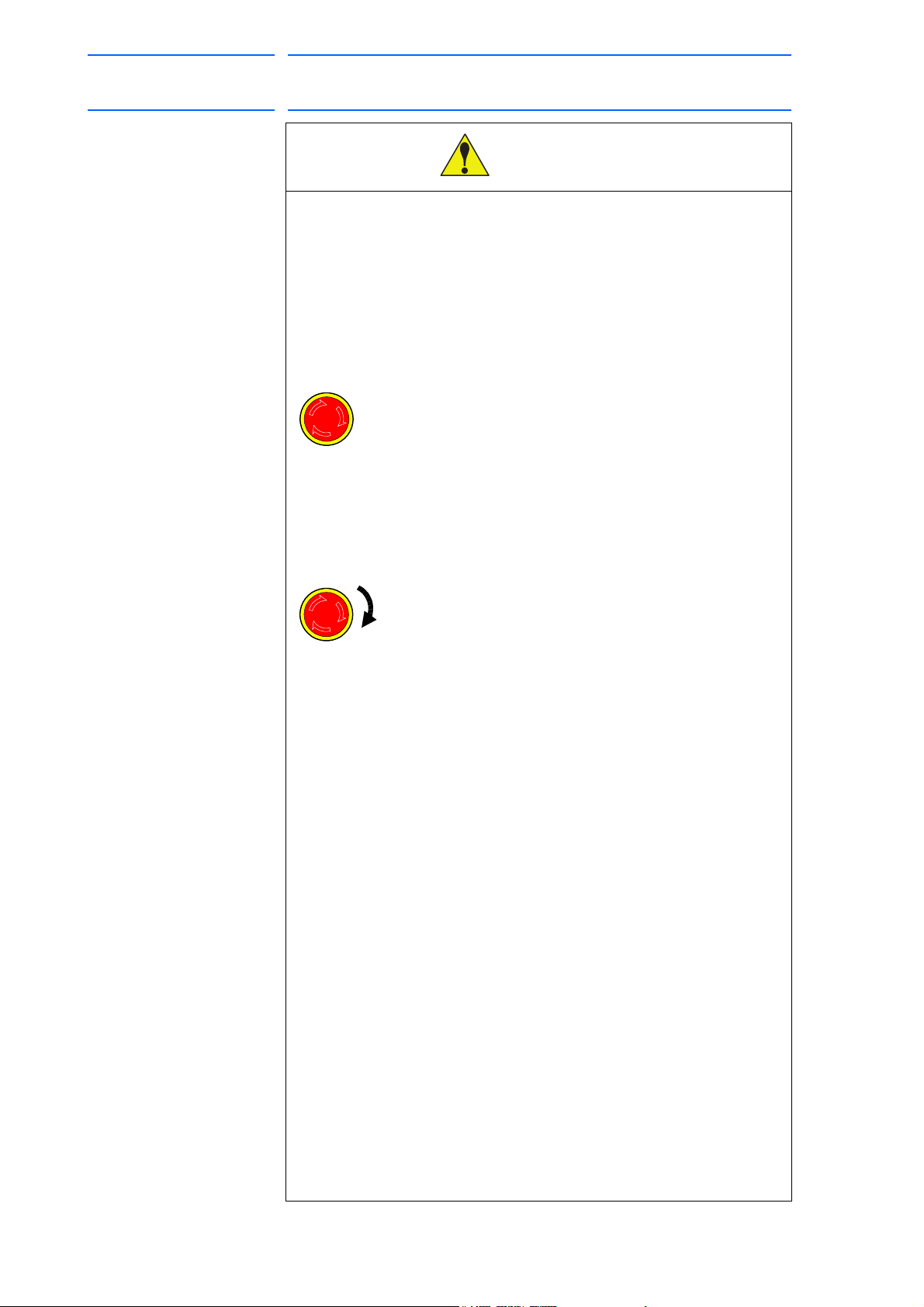
• Before operating the manipulator, check that servo power is turned
OFF pressing the emergency stop buttons on the front door of the
DX200 and the programming pendant.
When the servo power is turned OFF, the SERVO ON LED on the
programming pendant is turned OFF.
Injury or damage to machinery may result if the emergency stop circuit
cannot stop the manipulator during an emergency. The manipulator
should not be used if the emergency stop buttons do not function.
Figure 1: Emergency Stop Button
• Once the emergency stop button is released, clear the cell of all
items which could interfere with the operation of the manipulator.
Then turn the servo power ON.
Injury may result from unintentional or unexpected manipulator motion.
Figure 2: Release of Emergency Stop
• Observe the following precautions when performing teaching
operations within the P-point maximum envelope of the
manipulator:
– Be sure to use a lockout device to the safeguarding when going
inside. Also, display the sign that the operation is being
performed inside the safeguarding and make sure no one closes
the safeguarding.
– View the manipulator from the front whenever possible.
– Always follow the predetermined operating procedure.
– Keep in mind the emergency response measures against the
manipulator’s unexpected motion toward you.
– Ensure that you have a safe place to retreat in case of
emergency.
Improper or unintended manipulator operation may result in injury.
• Confirm that no person is present in the P-point maximum envelope
of the manipulator and that you are in a safe location before:
– Turning ON the power for the DX200.
– Moving the manipulator with the programming pendant.
– Running the system in the check mode.
– Performing automatic operations.
Injury may result if anyone enters the P-point maximum envelope of the
manipulator during operation. Always press an emergency stop button
immediately if there is a problem.
The emergency stop buttons are located on the right of front door of the
DX200 and the programming pendant.
vi
HW1481803
Page 7

165467-1CD
CAUTION
7 of 48
Pendant Oscilloscope
Function
• Perform the following inspection procedures prior to conducting
manipulator teaching. If problems are found, repair them
immediately, and be sure that all other necessary processing has
been performed.
– Check for problems in manipulator movement.
– Check for damage to insulation and sheathing of external wires.
• Always return the programming pendant to the hook on the cabinet
of the DX200 after use.
The programming pendant can be damaged if it is left in the
manipulator's work area, on the floor, or near fixtures.
• Read and understand the Explanation of Warning Labels in the
DX200 Instructions before operating the manipulator:
Definition of Terms Used Often in This Manual
The MOTOMAN is the YASKAWA industrial robot product.
The MOTOMAN usually consists of the manipulator, the controller, the
programming pendant, and the manipulator cables.
In this manual, the equipment is designated as follows:
Equipment Manual Designation
DX200 controller DX200
DX200 programming pendant Programming pendant
Cable between the manipulator and the
controller
Descriptions of the programming pendant, buttons, and displays are
shown as follows:
Equipment Manual Designation
Programming
Pendant
Character
ys
Ke
Symbol Keys
Axis Keys
Number Keys
The keys which have characters printed on
them are denoted with [ ].
ex. [ENTER]
“Axis Keys” and “Number Keys” are generic
names for the keys for axis operation and
number input.
Manipulator cable
Keys pressed
simultaneously
Displays The menu displayed in the programming
When two keys are to be pressed
simultaneously, the keys are shown with a “+”
sign between them, ex. [SHIFT]+[COORD]
pendant is denoted with { }.
ex. {JOB}
vii
HW1481803
Page 8
Pendant Oscilloscope
NOTE
(937) 847-3200
8 of 48
Function
Description of the Operation Procedure
In the explanation of the operation procedure, the expression “Select • • •”
means that the cursor is moved to the object item and the SELECT key is
pressed, or that the item is directly selected by touching the screen.
Registered Trademark
In this manual, names of companies, corporations, or products are
trademarks, registered trademarks, or brand names for each company or
corporation. The indications of (R) and TM are omitted.
Customer Support Information
If you need assistance with any aspect of your Pendant Oscilloscope
Function system, please contact Motoman Customer Support at the
following 24-hour telephone number:
165467-1CD
For routine technical inquiries, you can also contact Motoman Customer
Support at the following e-mail address:
techsupport@motoman.com
When using e-mail to contact Motoman Customer Support, please provide
a detailed description of your issue, along with complete contact
information. Please allow approximately 24 to 36 hours for a response to
your inquiry.
Please use e-mail for routine inquiries only. If you have an
urgent or emergency need for service, replacement parts,
or information, you must contact Motoman Customer
Support at the telephone number shown above.
Please have the following information ready before you call:
• System Pendant Oscilloscope Function
• Robot
• Primary Application
• Controller DX200
• Software Version Access information on the
Programming Pendant’s LCD
display screen by selecting {MAIN
MENU} - {SYSTEM INFO} {VERSION}
• Robot Serial Number Located on the robot data plate
• Robot Sales Order Number Located on the DX200 controller
data plate
viii
HW1481803
Page 9

165467-1CD
9 of 48
Pendant Oscilloscope
Function
Table of Contents
Table of Contents
1 Overview ......................................................................................................................................... 1-1
1.1 Pendant Oscilloscope Function ......................................................................................... 1-1
1.2 Specification ...................................................................................................................... 1-2
1.3 Setup ................................................................................................................................. 1-2
2 Setting and Operation for Data Measurement ................................................................................ 2-1
2.1 Startup of Pendant Oscilloscope Function......................................................................... 2-1
2.2 Main Screen Configuration ................................................................................................ 2-2
2.2.1 Main Screen (Not In-measurement Mode) ........................................................... 2-2
2.2.2 Main Screen (In-measurement Mode).................................................................. 2-3
2.3 Setting Measurement Conditions....................................................................................... 2-4
2.3.1 Channel Setting Window ...................................................................................... 2-4
2.3.2 CH Display Setting Panel ..................................................................................... 2-8
2.3.3 TimeScale Setting Panel .................................................................................... 2-10
2.3.4 Trigger Setting Panel.......................................................................................... 2-11
2.4 Starting and Ending Measurement .................................................................................. 2-15
2.4.1 Continuous Mode ............................................................................................... 2-15
2.4.2 Trigger Mode ...................................................................................................... 2-16
2.5 Termination and Minimization of Pendant Oscilloscope Function ................................... 2-17
2.5.1 Termination of PP Oscilloscope ......................................................................... 2-17
2.5.2 Minimizing PP Oscilloscope Application............................................................. 2-17
3 Saving and Loading the Measurement Data................................................................................... 3-1
3.1 SaveMode Setting Panel ................................................................................................... 3-1
3.1.1 Data File Name and Save Destination ................................................................. 3-1
3.1.2 CSV File ............................................................................................................... 3-2
3.2 Load Panel ........................................................................................................................ 3-3
4 Other Functions .............................................................................................................................. 4-1
4.1 Zoom Function................................................................................................................... 4-1
4.1.1 During Execution of Zoom Function ..................................................................... 4-2
4.2 Cursor Measurement Function .......................................................................................... 4-3
4.2.1 Cursor Measurement Parameters ........................................................................ 4-5
ix
HW1481803
Page 10

165467-1CD
10 of 48
Pendant Oscilloscope
Function
4.3 Job Step No. Saving Function ........................................................................................... 4-6
4.3.1 Channel Setting .................................................................................................... 4-7
4.3.2 Adjustment of Acquisition Time of Job Name and Step No.................................. 4-7
4.4 Operation Function by Dedicated Input ............................................................................. 4-8
4.4.1 Dedicated Input Signal.......................................................................................... 4-8
4.4.2 Dedicated Output Signal..................................................................................... 4-10
5 Supplementary Explanation ............................................................................................................ 5-1
5.1 Division [div]: Unit for Measurement Screen Position ........................................................ 5-1
5.2 Reference Unit ................................................................................................................... 5-2
6 Error Messages............................................................................................................................... 6-1
Table of Contents
x
HW1481803
Page 11

165467-1CD
11 of 48
Pendant Oscilloscope
Function
1Overview
1.1 Pendant Oscilloscope Function
1 Overview
1.1 Pendant Oscilloscope Function
Pendant Oscilloscope Function (hereinafter referred to as “PP
oscilloscope”) is the monitoring function of speed reference, torque
reference, as well as of concurrent I/O signals of each robot axis on the
Programming Pendant. The PP oscilloscope is configured by the
software, which requires no special hardware equipment. By carrying out
the PP oscilloscope function, the pendant oscilloscope application
(hereinafter referred to as “PP oscilloscope application”) starts on the
Programming Pendant.
Equipped with an integral display screen containing the waveform display
window and the condition setting panel, the PP oscilloscope application
enables to perform several processes from condition setting to
measurement at a time. Other available functions include Trigger function
that stops the data acquisition at a given condition, Measure and display
function of maximum/minimum values after data acquisition, Zoom
function that displays the waveform data in a magnified view, and data
output function in a format available on the computer. Fig. 1-1 shows a
typical display of PP oscilloscope.
Fig. 1-1: Display of PP Oscilloscope
START HOLD
TEACH
REMOTE
PLAY
Programming
pendant
Waveform display area
Condition setting panel
1-1
HW1481803
Page 12

Pendant Oscilloscope
NOTE
12 of 48
Function
1 Overview
1.2 Specification
1.2 Specification
Main specification of the PP oscilloscope is listed in Table 1-1 below:
Table 1-1: Main Specifications of PP Oscilloscope
Parameter Specification Description
Measurement data
type
Maximum channel
number
Sampling time 4.0, 8.0, 16.0, 32.0, 64.0
Maximum data length 50 [s] to 100 [s] Indicates data length that can be recorded at a
Waveform acquisition
mode
Trigger condition ○Trigger for measurement
Data saving format CSV
Speed reference, Speed
FB, Torque reference,
Concurrent I/O signal,
Register value
10 channels Number of channels that can be measured at the same
[ms]
Continuous mode
Trigger mode
waveform
- Up trigger
- Down trigger
- Up&Down trigger
○Alarm trigger
JPG
Number of channels that can be measured at the same
time.
time.
Indicates time interval for data sampling.
Smaller values enable more detailed measurement data,
but shorten the data record time due to much data volume.
measurement. Some setting of sampling time can limit the
maximum data length available.
Selects the mode according to the Trigger state
(valid/invalid):
○Trigger Invalid: Continuous
The Continuous mode displays the acquired data in a timeseries order.
○Trigger Valid: Trigger
The Trigger mode automatically stops the measurement and
displays waveform when the trigger conditions are satisfied.
Other than normal waveform triggers, alarm trigger is also
included.
Saves the acquired data in CF or USB memory with the
CSV (Comma Separated Value) format.
Saves the displayed data on the screen in CF or USB
memory with the JPG (Joint Photographic Experts Group)
format.
165467-1CD
1.3 Setup
The register value output function is applicable from version
DN1.61.00A(--)-00.
To activate the function, the optional parameters of the pendant
oscilloscope function need to be effective (note that the user cannot
change the parameter setting).
For the parameter setting other than specified above, contact a Yaskawa
sales representative.
1-2
HW1481803
Page 13
165467-1CD
13 of 48
Pendant Oscilloscope
Function
2 Setting and Operation for Data Measurement
2.1 Startup of Pendant Oscilloscope Function
2 Setting and Operation for Data Measurement
This chapter describes setting and operation required for the
measurement.
Basically the PP oscilloscope is operated by touching on the screen; for
pull-down selection box or entry box,
however, the Cursor Keys enable the cursor operation, and [SELECT],
[ENTER] or [CANCEL] key enables selection, determination, or cancel,
just as the normal operation on the pendant screens.
In performing numerical input using an entry box, first activate the
parameter to a selective state by [SELECT] key, input numerical values by
the Number Keys of the pendant, and press [ENTER] key to determine it.
To cancel the input numerical values, press [CANCEL] key in the selective
state.
2.1 Startup of Pendant Oscilloscope Function
The PP oscilloscope can be started up by the following step:
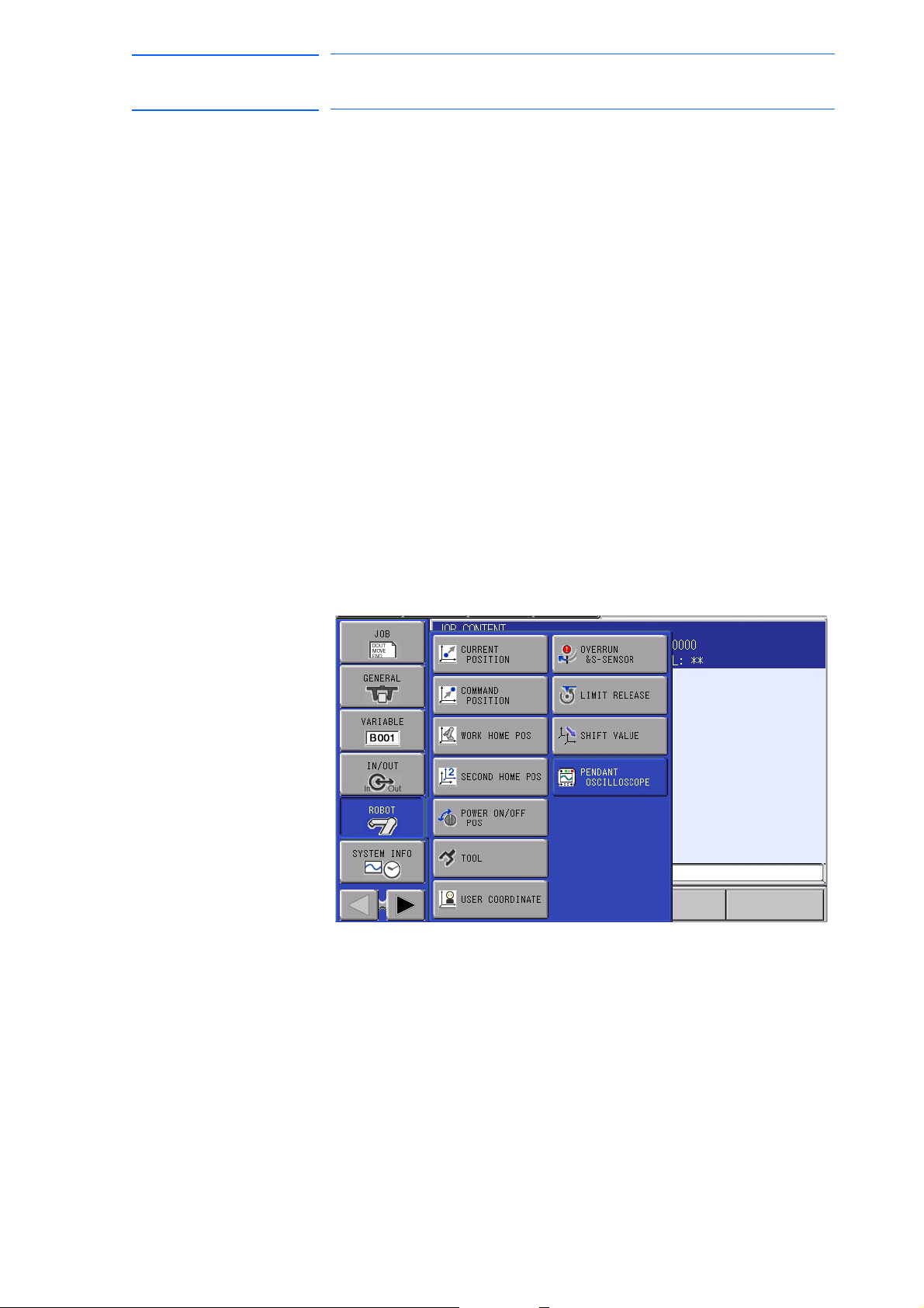
1. Select {ROBOT} from the menu in the left of screen.
2. Select {PENDANT OSCILLOSCOPE} from the expanded menu (see
Fig. 2-1).
Fig. 2-1: PP Oscilloscope Startup Menu
2-1
HW1481803
Page 14
Pendant Oscilloscope
14 of 48
Function
2.2.1 Main Screen (Not In-measurement Mode)
165467-1CD
2 Setting and Operation for Data Measurement
2.2 Main Screen Configuration
2.2 Main Screen Configuration
Here explains the configuration of the Main screen.
The PP oscilloscope is displayed on the entire screen of Programming
Pendant. The main screen has two types of modes; in-measurement and
without not in-measurement (Waiting), in which functions or availability of
some buttons are changed.
Condition setting is only available in not in-measurement mode (Waiting).
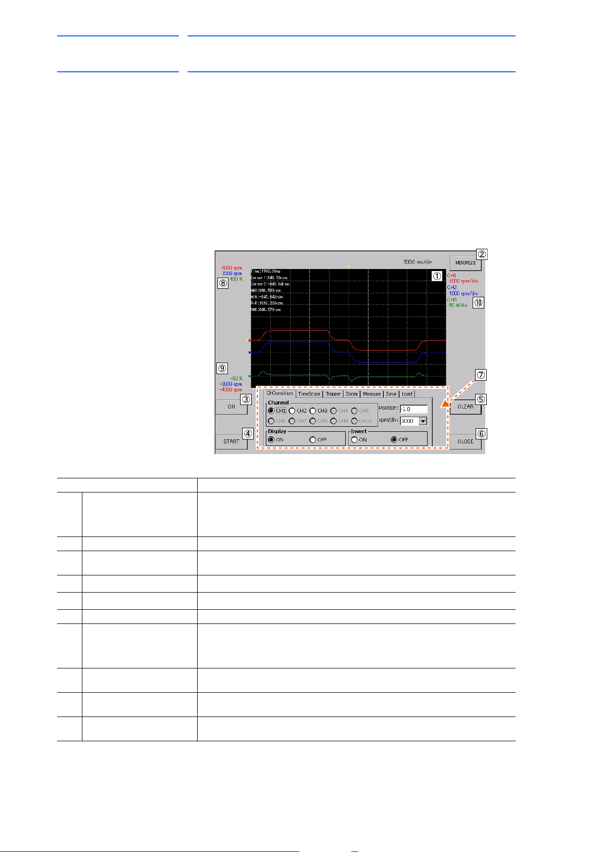
Main screen of not in-measurement mode (Waiting) is shown in Fig. 2-2
below with description.
Fig. 2-2: Main Screen (Not In-measurement Mode)
Name Function
Waveform display area Displays measured data waveform. When the data is not yet acquired soon
after the startup or when the data is cleared, nothing is shown here.
At the upper left of the area, measurement value obtained by the cursor
measurement function is displayed.
{MINIMIZE} button Minimizes the PP oscilloscope application.
{CH} button Opens the Channel Setting window. (For details of the Channel Setting
{START} button Starts the data measurement.
{CLEAR} button Deletes the displayed data waveform.
window, refer to section 2.3.1 “Channel Setting Window” on page 2-4)
{CLOSE} button Terminates the PP oscilloscope.
Condition setting panel Enables to set various conditions. Touching the upper tab enables to open
the setting screen corresponding to each parameter. (For details of each
condition setting, refer to section 2.3.2 “CH Display Setting Panel” on page 2-
8 to section 2.3.4 “Trigger Setting Panel” on page 2-11.)
Maximum display value Displays values and units at the uppermost of waveform display area by each
channel.
Minimum display value Displays values and units at the lowermost of waveform display area by each
channel.
Reference unit Displays the reference unit by each channel. For details of the reference unit,
refer to section 5.2 “Reference Unit” on page 5-2.
On the Main screen, information by channels is displayed in each specific
color; for example in Fig. 2-2, information on CH3 is displayed in green,
where the reference unit is 50%/div, the maximum display value is 450%,
and the minimum display value is -50%.
2-2
HW1481803
Page 15
165467-1CD
NOTE
15 of 48
Pendant Oscilloscope
Function
2 Setting and Operation for Data Measurement
2.2 Main Screen Configuration
2.2.2 Main Screen (In-measurement Mode)
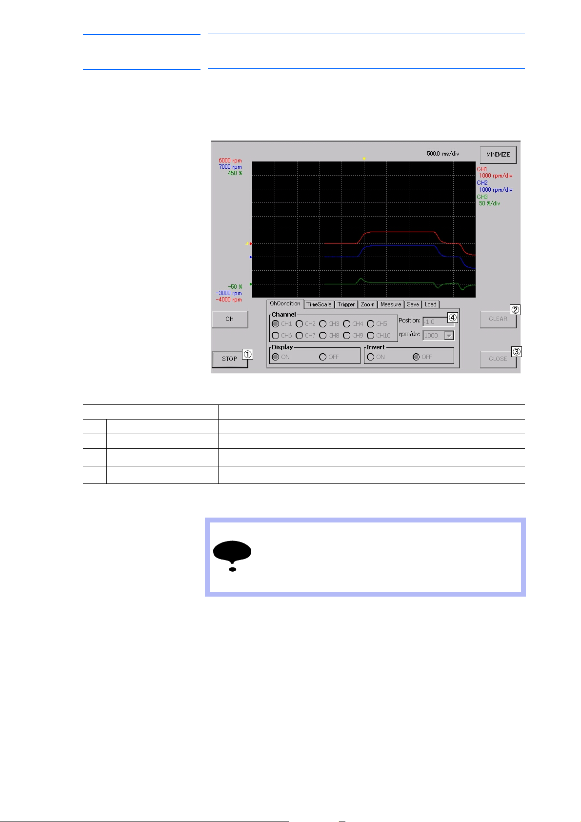
Main screen of In-measurement mode is shown in Fig. 2-3. In this mode,
the states of some buttons are changed. Here describes such buttons;
Fig. 2-3: Main Screen (In-measurement Mode)
Name Function
{STOP} button Switched from the {START} button, stops the data measurement.
{CLEAR} button In measurement mode, the button operation is disabled.
{CLOSE} button In measurement mode, the button operation is disabled.
Condition setting panel In measurement mode, the operation on tab is disabled.
Soon after switching the buttons {START} / {STOP}, button
operation is not available for a certain period of time to
avoid continuous pressing of the buttons.
When the buttons {START} / {STOP} are disabled, wait until
the operation becomes available.
2-3
HW1481803
Page 16

Pendant Oscilloscope
NOTE
16 of 48
Function
2.3.1 Channel Setting Window
165467-1CD
2 Setting and Operation for Data Measurement
2.3 Setting Measurement Conditions
2.3 Setting Measurement Conditions
Here describes how to set the measurement conditions on the channel
setting window and the condition setting panel.
Pressing the {CH} button on the Main screen opens the channel setting
window. Fig. 2-4 shows the typical display example of the channel setting
window. On this window, data type for measurement at each channel,
measurement target axis, and measurement interval of each data can be
set.
Fig. 2-4: Channel Setting Window
Sampling time
Sets the sampling interval of the data to be acquired. Settable options
are 4.0, 8.0, 16.0, 32.0, and 64.0 [ms], each of which corresponds to
the sampling frequencies of 250, 125, 62.5, 31.25, and 15.625 [Hz],
respectively.
Measurement valid/invalid check box
Requires setting for each channel, where the channel with a check
mark becomes valid for measurement.
When the multiple channels are to be valid, the channel numbers are
not necessarily to be sequential.
The more the channels are available, the more the process
is overloaded, and it affect the data updating speed in the
waveform display area; it is recommended that
unnecessary channels, if any, should be set to invalid.
2-4
HW1481803
Page 17

165467-1CD
NOTE
17 of 48
Pendant Oscilloscope
Function
2 Setting and Operation for Data Measurement
2.3 Setting Measurement Conditions
Tar get
Requires setting for each channel, where the setting of output signal
type is available.
Servo: Enables to select the servo CPU signals at the option .
I/O signal: Enables to input the concurrent I/O signal at the option .
Register: Enables to input the register number at the option .
Signal selection
Requires setting for each channel.
When {Servo} is selected at the option : Select speed reference,
speed feedback, or torque reference.
When {I/O signal} is selected at the option : Input signal number of
concurrent I/O. For the details of concurrent I/O, refer to “DX200
Concurrent I/O Instruction Manual (165294-1CD).”
Requirements on Concurrent I/O Signal
The concurrent I/O signal is updated in every 4.0 [ms].
Whereas when the PP oscilloscope allows the setting of
sampling time as 8.0 [ms] or more, the measurement data
has a delay time up to as long as that of the sampling time.
Even when the sampling time is 4.0 [ms], the signal turning
ON/OFF only for 4.0 [ms] may have data skipped; ensure to
keep the time interval of 20 [ms] or more between the signal
ON and OFF for the measurement target of concurrent I/O
signal.
When {Register} is selected at the option : Input register number.
Input the numerical value between M000 and M999.
Axis selection
Set the target axis for data acquisition. (Only when Servo is selected at
option Tar ge t )
One servo board (SRDA-EAXA21A) can connect up to 9 motors.
Furthermore, up to 8 servo boards can be connected to a system. This
means that the maximum axis configuration on a system allows
simultaneous connection of 72 axes of motors.
The PP oscilloscope specifies the measurement target axis by the
unique number of physical connection among these 72 axes. This is
called as “physical axis connection”.
Under the basic system configuration of a servo board, the physical
axes 1 to 6 are occupied by robot axis, and external axes are
connected to the physical axes 7, 8, and 9. When every servo board is
added, the number of physical axis is represented by offsetting each
+9. This relationship is shown in the following table Table 2-1:
Table 2-1: Relationship between the number of servo board and the
physical axis number (Sheet 1 of 2)
No. of servo board Physical axis number of the board
SV#1 1 to 9
SV#2 10 to 18
SV#3 19 to 27
2-5
HW1481803
Page 18

Pendant Oscilloscope
18 of 48
Function
165467-1CD
2 Setting and Operation for Data Measurement
2.3 Setting Measurement Conditions
Table 2-1: Relationship between the number of servo board and the
physical axis number (Sheet 2 of 2)
No. of servo board Physical axis number of the board
SV#4 28 to 36
SV#5 37 to 45
SV#6 46 to 54
SV#7 55 to 63
SV#8 64 to 72
The following example shows the typical specification of physical axis
number in the main system configuration.
Example:
○Normal 6-axis robot, R1 to R8
Target axis SL URBT
Axis selection
No. (R1)
Axis selection
No. (R2)
Axis selection
No. (R3)
Axis selection
No. (R4)
Axis selection
No. (R5)
Axis selection
No. (R6)
Axis selection
No. (R7)
Axis selection
No. (R8)
123456
10 11 12 13 14 15
19 20 21 22 23 24
28 29 30 31 32 33
37 38 39 40 41 42
46 47 48 49 50 51
55 56 57 58 59 60
64 65 66 67 68 69
○7-axis single-arm robot (such as SIA), R1 to R8
Target axis S L URBTE
Axis selection
No. (R1)
Axis selection
No. (R2)
Axis selection
No. (R3)
Axis selection
No. (R4)
Axis selection
No. (R5)
Axis selection
No. (R6)
Axis selection
No. (R7)
Axis selection
No. (R8)
1234567
10 11 12 13 14 15 16
19 20 21 22 23 24 25
28 29 30 31 32 33 34
37 38 39 40 41 42 43
46 47 48 49 50 51 52
55 56 57 58 59 60 61
64 65 66 67 68 69 70
2-6
HW1481803
Page 19

165467-1CD
19 of 48
Pendant Oscilloscope
Function
2 Setting and Operation for Data Measurement
2.3 Setting Measurement Conditions
○7-axis dual-arm robot (such as SDA)
Target axis SL URBT E
Axis selection
No. (R1)
Axis selection
No. (R2)
Target axis
1234567
10 11 12 13 14 15 16
EX1
Axis selection
No. (S1)
8
EX1 in this table corresponds to the waist axis (external axis) of dual-arm
robot.
○Normal 6-axis robot + external axis, R1 to R8 (R1 + S1 [3-axis] setting)
Target axis SL URBT
Axis selection
No. (R1)
Target axis
Axis selection
No. (S1)
123456
EX1 EX2 EX3
789
○7-axis robot + external axis (R1 + S1 [1-axis] + S2 [1-axis] setting)
Target axis SL URBT E
Axis selection
No. (R1)
Target axis
Axis selection
No. (S1)
Axis selection
No. (S2)
1234567
EX1
8
9
{OK} button
Closes the window with the change given on the channel setting
window reflected. When there is a measured waveform at the
waveform display area, the waveform data is cleared.
When no change has been given after the channel setting window is
opened, this button acts just as the {CANCEL} button.
{CANCEL} button
Closes the window without reflecting the change given on the channel
setting window. The waveforms data is not cleared.
2-7
HW1481803
Page 20

Pendant Oscilloscope
20 of 48
Function
2.3.2 CH Display Setting Panel
165467-1CD
2 Setting and Operation for Data Measurement
2.3 Setting Measurement Conditions
With the data measurement stopped, select (touch) the {ChCondition} tab
on the condition setting panel. Fig. 2-5 shows the typical display example
of the CH display setting panel.
Fig. 2-5: ChCondition Setting Panel
This panel allows the setting of panel display targeted to the channels
validated in the channel setting window.
Channel
Select the target channel for setting operation. Upon the channels set
here, the setting change given to the following options to is
reflected.
Note that the invalid channels are disabled (in which the radio button is
inoperable), and cannot be selected.
Display
Enables to select either to display {ON} or hide {OFF} the waveform
data of target channel. The data is internally stored even when the data
is measured with the Display {OFF}, and the corresponding waveform
data is displayed when Display {ON} is selected.
Invert
Enables to select either to invert the waveform data of target channel or
not. Selecting Invert {ON} inverts the display of waveform data in a
waveform display area between positive and negative. Selecting Invert
{OFF} returns to the original state.
2-8
HW1481803
Page 21

165467-1CD
21 of 48
Pendant Oscilloscope
Function
2 Setting and Operation for Data Measurement
2.3 Setting Measurement Conditions
Position
Sets the zero position of target channel. Specify the zero point within
the range of -5.0 to 5.0 [div] in the vertical axis of waveform display
area.
On the extreme left of waveform display area, a marker is provided
showing a zero point for each channel in which the current zero point
can be confirmed (see Fig. 2-6).
Fig. 2-6: Zero Point Marker
Zero point
maker
Unit (rpm/div, %/div, U/div)
Selects the reference unit of target channel in the vertical axis scale.
(For description of the unit, refer to section 5.2 “Reference Unit” on
page 5-2.)
Displayed unit and its selection depend on the signal output by the
target channel.
Speed reference, Speed FB:
Unit [rpm/div]: selectable among 250, 500, 1000, and 2000
Torque reference:
Unit [%/div]: selectable among 33, 50, 66, and 100
Concurrent I/O signal:
Unit [U/div]: selectable among 0.2, 0.5, 1.0, 2.0, 5.0, and 10.0
Register:
Unit [-/div]: selectable among 1, 2, 5, 10, 20, 50, 100, 200, 500, 1000,
2000, 3277, 5000, 6554, 10000, 13107, 20000, 32768, 50000 and
65535.
2-9
HW1481803
Page 22

Pendant Oscilloscope
22 of 48
Function
2.3.3 TimeScale Setting Panel
165467-1CD
2 Setting and Operation for Data Measurement
2.3 Setting Measurement Conditions
With the data measurement stopped, touch {TimeScale} tab on the
condition setting panel. Fig. 2-7 shows the typical display example of
TimeScale setting panel.
Fig. 2-7: TimeScale Setting Panel
ms/div
Sets the time for the horizontal axis of the waveform display area. The
value selected here should be the time width [ms] per division of
horizontal axis. Since there are 10 divisions in the entire horizontal
axis, the eventual data length is 10 times of the specified value.
Selectable range of ms/div depends on the combination of sampling
time set on the Channel Setting window:
With the sampling time of 4 [ms]:
Up to 5000 [ms/div] (data length: 50 [s])
With the sampling time of 8 [ms] or more:
Up to 10000 [ms/div] (data length: 100 [s])
2-10
HW1481803
Page 23

165467-1CD
Data before Trigger 3[s]
Data length
Pre-trigger
Data after Trigger 7[s]
Trigger level
Zero point of
waveform display
Zero point of
channel
Horizontal axis
23 of 48
Pendant Oscilloscope
Function
2 Setting and Operation for Data Measurement
2.3 Setting Measurement Conditions
2.3.4 Trigger Setting Panel
With the data measurement stopped, select (touch) {Trigger} tab on the
condition setting panel. Fig. 2-8 shows the typical display example of
Trigger setting panel.
This panel allows the setting of trigger function.
Fig. 2-8: Trigger Setting Panel
The trigger function is the function to automatically stop the measurement
and display the waveform at the point where a certain condition is satisfied
during the data measurement.
As trigger conditions, three options are available: when the target channel
data exceeds or falls below the specified value (trigger level), or when any
alarm occurs.
The data stop position is determined by Pre-trigger. The measurement
result is displayed so that the position satisfying the trigger conditions
becomes the Pre-trigger position. For example in Fig. 2-9, the data length
is 10 [s] and the specified Pre-trigger is 3 [div] in horizontal axis. This
allows the setting where the data before the trigger is acquired for 3
seconds, and the data after the trigger is acquired for 7 seconds.
Fig. 2-9: Outline of Trigger Function
CH
Select the channel as trigger target. Only the valid channel is
selectable.
2-11
HW1481803
Page 24

Pendant Oscilloscope
Pre-trigger
maeker
24 of 48
Function
165467-1CD
2 Setting and Operation for Data Measurement
2.3 Setting Measurement Conditions
TrgType (Trigger type)
Select the trigger type to use. Selectable options are Up, Down,
Up&Down, and Alarm.
When selecting Alarm, some of the setting parameters of Trigger
Conditions are changed.
Table 2-2: Characteristics of Trigger Type
Trigger type Trigger condition
Up When the trigger target channel data exceeds the trigger level
Down When the trigger target channel data falls below the trigger level
Up&Down When the trigger target channel data is either over or below the
trigger level
Alarm When the alarm assigned to alarm number occurs
PreTrg (Pre-trigger)
Specify the pre-trigger position by the horizontal axis division
(0 to 10.0).
Current pre-trigger position is shown by a marker on the upper part of
the waveform display area (see Fig. 2-10).
Fig. 2-10: Pre-trigger Marker
2-12
HW1481803
Page 25

165467-1CD
NOTE
Trigger level
marker
25 of 48
Pendant Oscilloscope
Function
2 Setting and Operation for Data Measurement
2.3 Setting Measurement Conditions
Level
Specify the trigger level by the vertical division (-10.0 to +10.0).
The current trigger level is shown by a marker on the left of the
waveform display area (see Fig. 2-11).
The marker shape depends on the selected trigger type.
Fig. 2-11: Trigger Level Marker
The value specified here is regarded as a position with the
zero point of trigger target channel as reference. When the
trigger level is specified as 2.5 [div] with the channel zero
position of -2.0 [div] (in vertical axis), the displayed position
of trigger level on the waveform display area is 0.5 [div] (in
vertical axis). (See the example of Fig. 2-9.)
TriggerMode
Switches the valid/invalid state of trigger. According to this setting, the
waveform data acquisition mode is switched.
• Invalid: Continuous mode
When the waveform data measurement is started, the acquired data is
continuously displayed in a time-series order.
• Valid: Trigger mode
The measurement is automatically stopped when the trigger conditions
are satisfied, and the waveform is displayed.
○When {Alarm} is selected as TrigType:
When {Alarm} is selected as the trigger type, the only condition for the
trigger is when the target alarm specified
here by the number occurs. The alarm trigger does not depend on the
channel setting, so the settings of {CH} or {Level} are not referred.
2-13
HW1481803
Page 26

Pendant Oscilloscope
NOTE
26 of 48
Function
165467-1CD
2 Setting and Operation for Data Measurement
2.3 Setting Measurement Conditions
Fig. 2-12 shows the typical display example when the option {Alarm} is
selected as TrigType.
Fig. 2-12: Trigger Setting Panel (Alarm Trigger)
AlarmNo
Selecting {Alarm} as the trigger type switches {Level} turns to an entry
box of {AlarmNo}. Input a valid alarm number here. When a nonexistent alarm number is specified, an error occurs when the
measurement starts.
For details of alarm number, refer to “DX200 Maintenance manual
(165293-1CD)”.
Major alarms, when occur, may contain abnormal data
transmission between the controller hardware, and a
normal operation of pendant oscilloscope cannot be
guaranteed.
It is recommended that the target alarm number as the
alarm trigger should be Minor or User alarms rather than
Major alarms.
2-14
HW1481803
Page 27

165467-1CD
SUPPLE-
MENT
27 of 48
Pendant Oscilloscope
Function
2 Setting and Operation for Data Measurement
2.4 Starting and Ending Measurement
2.4 Starting and Ending Measurement
Here describes the step of actual data measurement. Ensure to start the
measurement after completing the condition setting described in section
2.3 “Setting Measurement Conditions” on page 2-4.
2.4.1 Continuous Mode
The Continuous mode is the mode in which the measurement data is
always displayed and updated in the time-series order. Follow the step
below:
1. Select OFF for {TriggerMode} on the Trigger setting panel.
2. Start the measurement by the {START} button. The data
measurement starts, and the data is displayed in the time-series order
on the waveform display area, and updated in series.
3. When the time passes longer than the specified data length from the
asurement start, the data is discarded from the oldest one, and the
me
new data is updated in series (see Fig. 2-13).
4. When the target waveform data is displayed on the waveform display
ea, press the {STOP} button to stop the measurement.
ar
Fig. 2-13: Continuous Mode
Flow of data update
Old data Latest data
Continuous mode enables to display the measurement data
in time-series order, but it does not necessarily assure the
real-time display. The data contain a delay to a certain
extent, and the delay can be extended as the measured data
is large in volume.
The following setting changes help for the challenging of
real-time display:
- Trying smaller number of available channels
- Trying longer sampling time
- Trying shorter data length
2-15
HW1481803
Page 28

Pendant Oscilloscope
28 of 48
Function
2.4.2 Trigger Mode
165467-1CD
2 Setting and Operation for Data Measurement
2.4 Starting and Ending Measurement
The Trigger mode automatically stops the measurement when the trigger
condition is satisfied, and displays the waveform on the screen. Follow
the step below:
1. Set the trigger conditions on the Trigger setting panel.
2. Select ON for {TriggerMode}.
3. Start the measurement by the {START} button. This starts the data
asurement, and the waveform display area is turned to the waiting
me
state, and holds the state until the trigger condition is satisfied. On the
screen, a message “Waiting for trigger...” is displayed (see Fig. 2-14).
To cancel the measurement during this st
Fig. 2-14: Display of Trigger Mode “Waiting for trigger”
ate, press the {STOP} button.
4. When the trigger condition is satisfied, “Triggered” is displayed on the
screen (s
trigger position, the condition is held for as long as 100 seconds
ccording to the setting of data length and pre-trigger. To cancel the
a
measurement during this state, press the {STOP} button.
Fig. 2-15: Display of Trigger Mode “Triggered”
ee Fig. 2-15). To collect the waveform data later than the
5. When all the waveform data for an entire window is acquired, the
m
easurement automatically ends and the waveform is displayed.
2-16
HW1481803
Page 29

165467-1CD
29 of 48
Pendant Oscilloscope
Function
2 Setting and Operation for Data Measurement
2.5 Termination and Minimization of Pendant Oscilloscope Function
2.5 Termination and Minimization of Pendant Oscilloscope
Function
2.5.1 Termination of PP Oscilloscope
Pressing the {CLOSE} button on the Main screen terminates the PP
oscilloscope. Each condition setting parameter is automatically saved,
and the setting at the termination will be reflected at the next startup.
2.5.2 Minimizing PP Oscilloscope Application
Pressing the {MINIMIZE} button on the Main screen can minimize the PP
oscilloscope application. Minimizing means the PP oscilloscope changes
to the background process with running. When minimized PP
oscilloscope disappears just as the system termination does, but the
waveform measurement process is continued. This is useful when the
operations on the other system screens are necessary with the waveform
data measurement continued.
When an alarm or an error occurs on the controller, the PP oscilloscope
application is forcefully minimized to display the alarm preferentially.
When the PP oscilloscope application is minimized during the data
measurement, the following message is displayed on the message area of
the Pendant System screen: “Measuring the pendant oscilloscope data.”
(See Fig. 2-16).
Fig. 2-16: Message Display during the data measurement
Minimized PP oscilloscope application can be returned to the original state
by selecting {Pendant Oscilloscope} from the menu as in the startup
operation.
2-17
HW1481803
Page 30

Pendant Oscilloscope
NOTE
30 of 48
Function
3 Saving and Loading the Measurement Data
3.1 SaveMode Setting Panel
3 Saving and Loading the Measurement Data
This chapter describes the saving and loading of the measurement data.
3.1 SaveMode Setting Panel
With the data measurement stopped, select (touch) {Save} tab in the
condition setting panel. Fig. 3-1 shows the typical example of SaveMode
setting on the panel.
Fig. 3-1: SaveMode Setting Panel
165467-1CD
SaveMode
Enables to select Manual/Auto of the saving mode. In selecting the
automatic saving mode {Auto}, ensure to perform the setting with the
external CF or USB memory inserted to the Programming Pendant.
Automatic save mode
The automatic save function works only when the trigger
mode is valid.
The data is saved when the trigger conditions are satisfied
and the measurement is completed.
{HardCopy} button
Pressing the button enables to save the hard copy of the screen in CF
or USB memory.
{SaveCSV} button
It is available only when {Manual} is selected for the SaveMode option.
Pressing the button enables saving the measurement data into CF or
USB memory.
3.1.1 Data File Name and Save Destination
The measurement data is saved in the CSV (Comma Separated Value)
file format.
The file is automatically given a file name consisting of the time, date and
the year when the save operation starts (yyyymmdd_hhmmss.csv).
As the CSV file destination, a folder of the following address is
automatically created in the external CF or USB memory of the pendant,
and the data is saved in the folder:
¥PP_OSCILLOSCOPE¥csv¥user¥
The hard copy data of the screen is saved in the JPG (Joint Photographic
Experts Group) format.
3-1
HW1481803
Page 31

165467-1CD
NOTE
31 of 48
Pendant Oscilloscope
Function
3 Saving and Loading the Measurement Data
3.1 SaveMode Setting Panel
The file is automatically given a file name consisting of the time, date and
the year when the save operation starts (yyymmdd_hhmmss.jpg).
The JPG file is saved in the root folder in the external CF or USB memory
of the pendant.
When both CF and USB memory are inserted, USB memory is given
priority for the data storage destination.
3.1.2 CSV File
The CSV file contains the setting parameters shown in Table 3-1.
The CSV file can be used for file output of waveform data, as well as for
backup of the current setting status.
The setting parameters of TP oscilloscope are automatically
saved to the pendant when {OK} is pressed on the Channel
Setting window or {CLOSE} on the Main screen.
However, at system software version-up, these parameters
are initialized. Use the CSV file for backup as necessary.
Table 3-1: Parameters to Save for CSV Files
Parameter Description
Sampling time As left
Timescale setting
(data length)
Channel setting Valid/Invalid
Channel display setting Zero point position
Trigger setting Target channel
Waveform data Waveform data of available channel(s)
As left
Target
Signal
Target axis
Reference unit
Display ON/OFF
Invert ON/OFF
Trigger type
Trigger level
Pre-trigger
Alarm number
Valid/Invalid
3-2
HW1481803
Page 32

Pendant Oscilloscope
32 of 48
Function
165467-1CD
3 Saving and Loading the Measurement Data
3.2 Load Panel
3.2 Load Panel
With the data measurement stopped, select (touch) {Load} tab on the
condition setting panel. Fig. 3-2 shows the typical example of the Load
panel.
Fig. 3-2: Load Panel
The Load panel loads the CSV file previously saved to recreate the
waveform and setting parameters (those in Table 3-1) at that time.
The current setting parameters are overwritten by the loaded CSV file
data when the data is loaded.
Pull-down box for file selection
Select the file to load. The pull-down menu displays the file name
stored in the folder of the following address in the external CF or USB
memory of the Programming Pendant:
¥PP_OSCILLOSCOPE¥csv¥user¥
When both CF and USB memory are inserted, USB memory is given
priority.
When a file other than that saved in the PP oscilloscope is included in
the above folder, it may appear on the list, but it will cause an error
when it is loaded.
{LoadCSV} button
After selecting the file to load, touch the {LoadCSV} button.
A message, “Overwrite current setting. OK?” appears. Selecting {OK}
starts the data loading.
3-3
HW1481803
Page 33

165467-1CD
33 of 48
Pendant Oscilloscope
Function
4 Other Functions
4.1 Zoom Function
4 Other Functions
4.1 Zoom Function
With the data measurement stopped, select (touch) {Zoom} tab on the
condition setting panel. Fig. 4-1 shows the typical example of the Zoom
function setting panel.
This panel enables to set and perform the zoom function.
Fig. 4-1: Zoom Function Setting Panel
The Zoom function is the function to enlarge the specified range within the
waveform display area to the timescale direction.
Set the range to enlarge as in Fig. 4-2, to perform the Zoom function.
Fig. 4-2: Outline of Zoom Function
Center
Width
Waveform display area
Range to be zoomed
Center
Specify the center position in the zoom range by the division (0 to 10.0) in
the horizontal axis. The center position is not shown in the actual screen.
It is the center between two width lines.
When pressing [SHIFT] key + Cursor with {Zoom} tab opened, the center
position may move to right and left at 0.05[div]. And when keep pressing
[SHIFT] key + Cursor, the center position may move at high speed.
4-1
HW1481803
Page 34

Pendant Oscilloscope
NOTE
34 of 48
Function
4.1.1 During Execution of Zoom Function
165467-1CD
4 Other Functions
4.1 Zoom Function
Width
Specify the size of zoom range by width, with the center position specified
in the Center. The width is shown in the waveform display area by a white
line.
In case the width of the range to be zoomed extended outside the
waveform display area, the center position is automatically adjusted so
that the width fits inside the range.
{Zoom} button
Touching this button after setting of Center and Width zooms the specified
range.
When the Zoom function is performed, the currently displayed waveform
disappears, and the data in the zoom range is enlarged and displayed on
the waveform display area. Although the waveform before zoomed
temporarily disappears, it is retained inside the system; once canceling
the zoom function returns to the original state.
While the zoom function is performed, the {Zoom} button is switched to
the {ZoomCancel} button.
While the zoom function is performed, operations of the
{START} button and the {CH} button, and of the panels as
tab switch setting become unavailable. To enable these
operations, touch the {ZoomCancel} button.
4-2
HW1481803
Page 35

165467-1CD
35 of 48
Pendant Oscilloscope
Function
4 Other Functions
4.2 Cursor Measurement Function
4.2 Cursor Measurement Function
With the data measurement stopped, select (touch) the {Measure} tab on
the condition setting panel. Fig. 4-3 shows the typical example of the
Measure panel.
Fig. 4-3: Measure Panel and Cursor Display (with Vertical Cursor)
Measurement
parameters
Cursor
4
The cursor measurement function is the function to read the data within
the range selected by two cursors, calculate the values corresponding to
the specified measurement parameters, and display the result.
CursorType
Select the cursor type either from Horizontal or Vertical. Select the type
according to the usage. The {OFF} option makes the function
unavailable.
CH
Specify the channel to which the cursor measurement is targeted. The
channel specified as unavailable in the Channel Setting window cannot
be selected.
Cursor1, Cursor2
When the vertical cursor is selected in , specify the cursor position in
the horizontal division (0 to 10.0).
When the horizontal cursor is selected in , specify it in the vertical
division (-5.0 to 5.0).
The area enclosed by Cursor1 and Cursor2 becomes the target area of
cursor measurement. Even when the positions of Cursor1 and Cursor2
are switched, the target area is always the area inside these two lines.
4-3
HW1481803
Page 36

Pendant Oscilloscope
36 of 48
Function
165467-1CD
4 Other Functions
4.2 Cursor Measurement Function
The cursor is displayed by a white broken line on the waveform display
area.
When there is no target channel data within the specified cursor range,
a part of the measurement parameters is not calculated. When this
happens, the result is shown in hyphens (“-”).
CursorMode
When pressing [SHIFT] key + Cursor with {Zoom} tab opened, the
center position may move 0.05[div] to right and left. And when keep
pressing [SHIFT] key + Cursor, the position may move at high
speed.
When Horizontal cursor type is selected at
moves horizontally, and it moves vertically when Vertical cursor type is
selected.
Only the cursor 1 moves along the key input when “Cursor 1” is selected
and only cursor 2 moves when “Cursor 2” is selected. Also, both cursor
1 and 2 moves when “1 and 2” is selected.
on the display, the cursor
4-4
HW1481803
Page 37

165467-1CD
37 of 48
Pendant Oscilloscope
Function
4 Other Functions
4.2 Cursor Measurement Function
4.2.1 Cursor Measurement Parameters
○For horizontal cursor
With the cursor measurement valid, the measurement parameters and the
calculation result are automatically displayed at the upper left of waveform
display area. The type of measurement parameters in the horizontal
cursor is shown in Table 4-1.
Table 4-1: Measurement Parameters of Horizontal Cursors
Parameter Description
Cursor1 Value of measurement target channel at the Cursor1
Cursor2 Value of measurement target channel at the Cursor2
MAX Maximum value of measurement target channel between
Cursor1 and Cursor2
MIN Minimum value of measurement target channel between
Cursor1 and Cursor2
P-P (Peak to Peak: difference of MAX and MIN)
Absolute value of the result obtained by: MAX-MIN
○For vertical cursor
With the cursor measurement valid, the measurement parameters and the
calculation result are automatically displayed at the upper left of waveform
display area. The type of measurement parameters in the vertical cursor
is shown in Table 4-2.
Table 4-2: Measurement Parameters of Vertical Cursors
Parameter Description
Time Time width between Cursor1 and Cursor2
Cursor1 Value of measurement target channel at the Cursor1
Cursor2 Value of measurement target channel at the Cursor2
MAX Maximum value of measurement target channel between
Cursor1 and Cursor2
MIN Minimum value of measurement target channel between
Cursor1 and Cursor2
P-P (Peak to Peak: difference of MAX and MIN)
Absolute value of the result obtained by: MAX-MIN
RMS (RMS: Root Mean Square)
Data between Cursor1 and Cursor2; calculated actual value of
the measurement target channel
4-5
HW1481803
Page 38

Pendant Oscilloscope
NOTE
NOTE
38 of 48
Function
165467-1CD
4 Other Functions
4.3 Job Step No. Saving Function
4.3 Job Step No. Saving Function
When “1” is set to S2C1242, the job step No. saving function is enabled.
In this function, the job name and the step No. which are under execution
at the time are added to the waveform data of the CSV file, and the
waveform data and the job step No. are related and saved.
The job step No. saving function is available in the version
DN1.61.00A(--)-00 and the later.
Fig. 4-4: Example for Adding Items to Be Saved in CSV File (Job Name
and Step No.)
The job name and the step No. are saved only when the play mode
executes a job and when the teach mode executes a trial run or a NEXT
operation. In a JOG operation or an IO jog operation, the job name and
the step No. are not saved.
Table 4-3: Conditions that Job Name and Step No. Are Saved
Operation Saved/not
Playback Saved
Trial run Saved
Interlock + NEXT Saved
NEXT Saved
NEXT for P variable Not
IO jog Not
Jog operation Not
The job name and the step No. are assigned to the position
instruction. On the other hand, the waveform data interprets
the position instruction and acquires data when the motor
operates actually. Therefore, deviations of acquisition timing
for a certain time occurs between both data.
Be careful when referring to the data which is close to the
switching point of the step No.
4-6
HW1481803
Page 39

165467-1CD
39 of 48
Pendant Oscilloscope
Function
4 Other Functions
4.3 Job Step No. Saving Function
4.3.1 Channel Setting
Only one control group can be specified at one measurement time as the
control group which is targeted to acquire the job name and the step No.
The setting can be performed in Channel Setting screen of the PP
oscilloscope (Fig. 4-5).
When the job including a control group which is set in this item works, the
job name and the step No. are saved.
Fig. 4-5: Adding Items to "ControlGroup" of Channel Setting Screen
4.3.2 Adjustment of Acquisition Time of Job Name and Step No.
When the job cursor reaches END or when the other job is called (when
the assignment of the job name and the step No. to the targeted control
group are stopped), the job name and the step No. which are output lastly
can be kept recording for a certain time.
This can be performed when assignment of the job name and the step No.
are interrupted because of the deviation of the waveform against the
instruction.
S4C1039 can adjust this addition time (unit: msec, default value: 500 msec).
Fig. 4-6: Example for Acquisition Time of Job Name and Step No.
Range that job names and step Nos. are generally added
Additional time for acquiring
job names and step Nos.
CH1, Signal for indicating
"under running"
CH2, Speed FB CH3, Torque instruction
4-7
HW1481803
Page 40

Pendant Oscilloscope
NOTE
NOTE
NOTE
Rising
40 of 48
Function
165467-1CD
4 Other Functions
4.4 Operation Function by Dedicated Input
4.4 Operation Function by Dedicated Input
When “1” is set to S2C1244, the signal operation function is enabled.
This function makes the following operations performed on the
programming pendant executable externally by the dedicated input
signals.
• Starting PP oscilloscope
• Starting measurement
• Saving CSV file
Also, the PP oscilloscope status is output to the dedicated output signal,
and it can be externally referred.
The operation function by dedicated input is available in the
version DN1.61.00A(--)-00 and the later.
This function aims to start measurement externally without
operating and referring to the programming pendant.
Therefore, it has no dedicated input signal to stop
measurement.
For stopping measurement, use the trigger mode.
4.4.1 Dedicated Input Signal
40767 40766 40765 40764 40763 40762 40761 40760
SIN#608 SIN#607 SIN#606 SIN#605 SIN#604 SIN#603 SIN#602 SIN#601
OSC
SAVE START
40760: Starting Pendant Oscilloscope
Starts PP oscilloscope.
When PP oscilloscope is in minimized status, it is released.
This signal performs the same operation as the operation when
pressing {Robot}
When it is in one of the following status, pendant
oscilloscope cannot be started even if this signal is turned
ON.
After releasing the status, turn ON this signal.
→ {Pendant oscilloscope} from the main menu.
OSC
MEAS.START
OSC
STARTUP
• An error exists.
• Other external application is running.
4-8
HW1481803
Page 41

165467-1CD
Rising
NOTE
Rising
㻝㻌㼟㼑㼏㻚㻌㼛㼞㻌
㼘㼛㼚㼓㼑㼞
㻝㻌㼟㼑㼏㻚㻌㼛㼞㻌
㼘㼛㼚㼓㼑㼞
㻿㼕㼓㼚㼍㼘㻌㼍㼏㼏㼑㼜㼠㼍㼚㼏㼑㻌㼞㼑㼍㼐㼥
㻔㻡㻝㻝㻣㻞㻕
㻹㼑㼍㼟㼡㼞㼑㼙㼑㼚㼠㻌㼟㼠㼍㼞㼠㻌㼞㼑㼝㼡㼑㼟㼠
㻔㻠㻜㻣㻢㻝㻕
41 of 48
Pendant Oscilloscope
Function
4 Other Functions
4.4 Operation Function by Dedicated Input
40761: Pendant Oscilloscope Starting Measurement
Starts measurement.
This signal performs the same operation as the operation when
pressing [START] of PP oscilloscope.
40762: Pendant Oscilloscope Saving CSV File
Saves the measured data to the CSV file.
This signal performs the same operation as the operation when
pressing [Save CSV] of PP oscilloscope.
The measurement start requesting signal (40761) and the
CSV file saving requesting signal (40762) are monitored
only when the signal acceptance ready (51172) is ON.
In order to accept the request surely, put a requesting signal
with the following procedure.
• After the signal acceptance ready (51172) is turned ON,
wait for 1 second, and then put the signal.
• After putting the signal, ON status should be maintained for
1 second or longer.
4-9
HW1481803
Page 42

165467-1CD
State
State
SUPPLE-
MENT
State
42 of 48
Pendant Oscilloscope
Function
4 Other Functions
4.4 Operation Function by Dedicated Input
4.4.2 Dedicated Output Signal
Displays PP oscilloscope operation status. When PP oscilloscope is not
running, all signals are OFF.
50907 50906 50905 50904 50903 50902 50901 50900
SOUT#720 SOUT#719 SOUT#718 SOUT#717 SOUT#716 SOUT#715 SOUT#714 SOUT#713
MEASURING
PP-OSC
51177 51176 51175 51174 51173 51172 51171 51170
SOUT#936 SOUT#935 SOUT#934 SOUT#933 SOUT#932 SOUT#931 SOUT#930 SOUT#929
OSC
SAVE ERROR
OSC
SAVING
OSC
MEAS.ERROR
OSC I/O
READY
OSC
MINIMIZE
OSC
RUNNING
50903: Pendant Oscilloscope Under Measurement
Notifies that measurement is currently performed.
Only this signal varies regardless of S2C1244 setting.
51170: Pendant Oscilloscope Running
Notifies that PP oscilloscope is running.
This signal is turned ON even if PP oscilloscope is in minimized
status.
51171: Pendant Oscilloscope Minimized
Notifies that PP oscilloscope is in minimized status.
PP oscilloscope is minimized by the following factors:
• The {MINIMIZE} button is pressed.
• An alarm or an error occurs.
The minimized status can be cancelled by selecting {Pendant
oscilloscope} from the main menu or using the start
requesting signal (40760).
4-10
HW1481803
Page 43

165467-1CD
SUPPLE-
MENT
State
State
State
State
43 of 48
Pendant Oscilloscope
Function
4 Other Functions
4.4 Operation Function by Dedicated Input
51172: Pendant Oscilloscope IO Acceptance Ready
Notifies that PP oscilloscope is monitoring the start request
(40761) and the CSV file saving request (40762).
Only when the following conditions are satisfied, this signal is
turned ON.
• Measurement CH settings are completed.
• Not under measurement.
• Not under saving the CSV file.
• Not in the minimized status.
• Not under zooming (section 4.1.1 “During Execution of
Zoom Function” on page 4-2).
51173: Pendant Oscilloscope Measurement Error
Notifies that the measurement failed to start when the {START}
button or the start requesting signal (40761) tried to start
measurement.
Check that there are no errors in the measurement conditions.
This signal is turned OFF when newly starting measurement.
51174: Pendant Oscilloscope CSV File Under Saving
Notifies that the CSV file is under saving.
51175: Pendant Oscilloscope CSV File Error in Saving
Notifies that saving is failed when starting saving with the {Save
CSV} button or the CSV file saving requesting signal (40762).
Check the condition of the external storage device.
This signal is turned OFF when newly starting saving.
When requesting saving in the condition that the measurement
is never performed after starting PP oscilloscope, saving is not
performed but this signal is not turned ON.
4-11
HW1481803
Page 44

Pendant Oscilloscope
44 of 48
Function
5 Supplementary Explanation
5.1 Division [div]: Unit for Measurement Screen Position
5 Supplementary Explanation
Here explains some of the terms used in this manual.
5.1 Division [div]: Unit for Measurement Screen Position
The PP oscilloscope includes the operation that specifies the various
positions (or range) in the waveform display area, such as specifying zero
point of measurement channel, specifying cursor range, or zoom range.
To specify these positions, unit of “division [div]” is used. Here describes
the details.
The waveform display area is represented in a range of 10 vertical grids
and 10 horizontal grids. The cell consisted of a vertical grid and a
horizontal grid is called as Division [div], both for vertical axis and
horizontal axis. The vertical axis is divided into 10 cells, 5 for the upper
part and 5 for the lower part. The center is regarded as 0 [div], and the
maximum value in the upmost position is 5 [div], whereas the minimum
value in the bottom position is -5 [div]. For the horizontal axis, the left end
position is regarded as 0 [div], and the right end position is 10 [div]. The
outline is shown in Fig. 5-1.
165467-1CD
For example, in specifying 3 [div], if it is given to the vertical axis, it shows
the location
shows the location
Fig. 5-1: Illustration of Division in Waveform Display Area
Vertical direction
in Fig. 5-1,whereas if it is given to the horizontal axis, it
.
Horizontal direction
5-1
HW1481803
Page 45

165467-1CD
45 of 48
Pendant Oscilloscope
Function
5 Supplementary Explanation
5.2 Reference Unit
5.2 Reference Unit
Here describes the reference unit.
The data of measurement target has each unit, as shown in Table 5-1.
Table 5-1: Unit of Data
Data type Unit
Speed
reference
Speed
feedback
To rq u e
reference
Concurrent I/O No unit, for it is just an ON/OFF signal.
Register No unit, for it is just an register value.
[rpm]
Rotating speed of target axis motor in a minute
[rpm]
Actual rotating speed of target axis motor in one minute
[%]
Current torque reference value when the target axis motor rated
torque is converted as 100%.
To differentiate from other signal data, [U] (unit) is used for
expediency.
OFF: 0 U is output
ON: 1.0 U is output
Register value is output without changed.
Example: When the vertical scale is 100[-/div] and the target
register value is 200, the output of 2 divisions is given
.
When the speed reference is selected as a measurement signal of the
target channel, the initial value of the reference unit is 1000 [rpm/div].
This means that the speed is 1000 [rpm] when the output of vertical 1 [div]
is given from the target channel zero position. From this relationship, the
outline of waveform data output on the waveform display area can be
grasped.
Example: with the setting of 1000 [rpm/div]:
Output of 2.0 [div]: 2000 [rpm]
Output of -3.3 [div]: -3300 [rpm]
Since the reference unit can be changed in the {ChCondition} tab, the
waveform display scale in the vertical direction can be changed
accordingly.
Example: with the actual output of 1000 [rpm]:
Setting of 1000 [rpm/div]: Output of 1 division
Setting of 500 [rpm/div]: Output of 2 divisions
5-2
HW1481803
Page 46

Pendant Oscilloscope
46 of 48
Function
6 Error Messages
165467-1CD
6 Error Messages
The pendant oscilloscope can output the messages for confirming the
operation or notifying the process completion. Especially when the data
acquisition error or abnormal setting should occur, the application outputs
error messages such as shown in Fig. 6-1 to notify the problem.
When any error message is displayed, first check the content, touch {OK}
to clear the message, and follow necessary countermeasures.
Fig. 6-1: Example of Error Message
Table 6-1 shows the list of error messages and the countermeasure.
Table 6-1: Error Messages and Countermeasures of PP Oscilloscope
(Sheet 1 of 2)
Error messages Countermeasures
Input the value between ** and **.
The value to ** decimal places can be
input.
Input the numeric value.
(**: numerical value)
The specified number for the alarm
trigger is not correct.
Review the setting.
Any trigger can be detected with this
setting.
Review the trigger level setting.
The axis number which doesn't exist
in the system has been specified.
Review the channel setting.
Input correct I/O number. The concurrent I/O number which does
Processing time insufficient.
Set slower sampling time or decrease
the number of available channels.
The input value is out of the limitation of
input box.
Retry inputting a correct value according
to the error message.
This error can occur in all of the input
boxes.
A non-existent number is specified as the
alarm number of alarm trigger. Retry
setting a correct number.
The trigger level is out of the waveform
display area due to excessively large
trigger level or channels zero position.
Check the trigger level setting.
The axis number which does not exist in
the system is specified to either of axes
in the channel setting window.
Set the correct number.
not exist is specified.
Set the correct number.
Process time for data acquisition is not
enough for the volume of measurement
data.
Set a slower sampling time, or decrease
the available channel number.
6-1
HW1481803
Page 47

165467-1CD
47 of 48
Pendant Oscilloscope
Function
6 Error Messages
Table 6-1: Error Messages and Countermeasures of PP Oscilloscope
(Sheet 2 of 2)
Error messages Countermeasures
The acceptable delaying range of
graph drawing exceeded. Implement
any of the following countermeasures.
- Set slower sampling time.
- Decrease the number of available
channels.
- Set shorter value for Time Scale
setting. (Shorten the data length.)
No corresponding data exists within
the zoom range.
Cannot recognize Flash Memory.
Setting for SaveMode is switched
from Auto to Manual.
Cannot recognize Flash Memory.
SaveMode is switched from Auto to
Manual.
Perform manual saving if necessary.
Failed in saving CSV file.
Perform manual saving if necessary.
Not enough disk space.
Make room for the file to perform
manual saving.
File format is not correct. The file to load has not been matched
Failed in loading CSV file. The file to load has been found not to be
File not specified. Specify the file to load.
Specified file not exist. The specified file does not exist on the
Failed in starting measurement. An error has occurred at measurement
Failed in obtaining measured
value.[**]
Measurement is canceled.
(**: numerical value)
Failed in completing measurement. The measurement process has not been
Process time for graph drawing is not
enough for the volume of measurement
data.
Set a slower sampling time, decrease the
available channel number, or set shorter
timescale value.
There is no measurement data within the
zoom range currently specified. Set the
zoom range again.
Insert CF or USB memory and set
SaveMode again.
Flash memory could not be recognized
at data save.
Insert CF or USB memory and retry data
saving manually.
An error has occurred in flash memory.
Try CF or USB memory insertion again
or replacement, and retry data saving
manually.
Assure enough disk space for CF or USB
memory.
with the data format of PP oscilloscope.
Check if the file has been correctly
saved.
the correct file for the PP oscilloscope.
The file cannot be loaded.
CF or USB memory.
start, and the measurement cannot be
started. Retry the measurement.
If the alarm persists, terminate the
pendant oscilloscope application, and
restart the application.
An error was found in the acquired
measurement data.
The system is forcefully turned into the
measurement stop condition. Retry the
measurement.
If the alarm persists, terminate the
pendant oscilloscope application, and
restart the application.
correctly completed.
Terminate the pendant oscilloscope
application, and restart the application.
6-2
HW1481803
Page 48

DX200 OPTIONS
48 of 48
INSTRUCTIONS
FOR PENDANT OSCILLOSCOPE FUNCTION
HEAD OFFICE
2-1 Kurosakishiroishi, Yahatanishi-ku, Kitakyushu 806-0004, Japan
Phone +81-93-645-7703 Fax +81-93-645-7802
YASKAWA America Inc. (Motoman Robotics Division)
100 Automation Way, Miamisburg, OH 45342, U.S.A.
Phone +1-937-847-6200 Fax +1-937-847-6277
YASKAWA Europe GmbHRobotics Divsion )
Yaskawastrasse 1, 85391 Allershausen, Germany
Phone +49-8166-90-100 Fax +49-8166-90-103
YASKAWA Nordic AB
Bredbandet 1 vån. 3 varvsholmen 392 30 Kalmar, Sweden
Phone +46-480-417-800 Fax +46-480-417-999
YASKAWA Electric (China) Co., Ltd.
22/F One Corporate Avenue No.222, Hubin Road, Huangpu District, Shanghai 200021, China
Phone +86-21-5385-2200 Fax 㧗86-21-5385-3299
YASKAWA SHOUGANG ROBOT Co. Ltd.
No7 Yongchang North Road, Beijing E&T Development AreaChina 100176
Phone
+86-10-6788-2858
Fax
+86-10-6788-2878
YASKAWA India Private Ltd. (Robotics Division)
#426, Udyog Vihar, Phase- IV,Gurgaon, Haryana, India
YASKAWA Electric Korea Co., Ltd
9F, KyoboSecuritiesBldg., 26-4, Yeouido-dong,Yeongdeungpo-gu, Seoul 150-737, Korea
Phone +82-2-784-7844 Fax +82-2-784-8495
YASKAWA Electric Taiwan Corporation
12F, No.207, Sec. 3, Beishin Rd., Shindian District, New Taipei City 23143, Taiwan
YASKAWA Electric (Singapore) PTE Ltd.
151 Lorong Chuan, #04-02A, New Tech Park, Singapore 556741
Phone +65-6282-3003 Fax +65-6289-3003
YASKAWA Electric (Thailand) Co., Ltd.
252/125-126 27th Floor, Tower B Muang Thai-Phatra Complex Building,
Rachadaphisek Road㧘Huaykwang, Bangkok 10320, Thailand
Phone
+66-2693-2200
PT. YASKAWA Electric Indonesia
Secure Building-Gedung B Lantai Dasar & Lantai 1 JI. Raya Protokol Halim Perdanakusuma,
Jakarta 13610, Indonesia
Fax +91-124-475-8542Phone +91-124-475-8500
Fax +886-2-8913-1513Phone +886-2-8913-1333
Fax
+66-2693-4200
Fax +62-21-2982-6741Phone +62-21-2982-6470
Specifications are subject to change without notice
for ongoing product modifications and improvements.
MANUAL NO.
HW1481803
1
 Loading...