

Page 1

For GPD 515/G5, GPD 503
Adjustable Frequency Drives
and VCD 703 Vector Control Drives
ANALOG SPEED REFERENCE (BIPOLAR) (AI-14B)
MODEL DS387
Before installing this option, a TECHNICALLY QUALIFIED INDIVIDUAL, who is familiar with this type of
equipment and hazards involved, should READ this ENTIRE INSTRUCTION SHEET.
IMPORTANT
This option may have been installed by the factory. However, certain steps can
only be completed at the installation site. Therefore, review and then perform
those steps which complete the installation process.
If you are installing this option in a: Use Section:
GPD 515/G5 ...................................... A (Sheet 2)
VCD 703 ............................................ B (Sheet 7)
GPD 503 ........................................... C (Sheet 11)
CAUTION
THIS OPTION CONTAINS ELECTROSTATIC SENSITIVE DEVICES. PERSONEL
SHOULD BE GROUNDED BEFORE REMOVING CONTENTS FROM THE
CARTON AND INSTALLING INTO THE EQUIPMENT.
WARNING
HAZARDOUS VOLTAGE CAN CAUSE SEVERE INJURY OR DEATH.
LOCK ALL POWER SOURCES FEEDING DRIVE IN "OFF" POSITION.
Yaskawa Electric America, Inc-www.drives.com
02Y00025-0296 Page 1 OF 14
REL. 08/23/91
Page 2
ANALOG SPEED REFERENCE
(BIPOLAR) (AI-14B) MODEL DS387
Section A: Installation in a GPD 515
INTRODUCTION
When installed, this option allows the user to interface three separate high resolution analog input signals, each of
which may be either current or voltage (13-bit plus sign). These signals can act as a direct replacement for the
three existing analog inputs available on the drive (3-channel individual mode), or the signals can be added together
and used as a single frequency reference (3-channel addition mode). Gain and Bias are adjustable for both modes
using drive parameters. Polarity (sign) of the speed reference controls direction of motor rotation.
INSTALLATION
A1. Disconnect all electrical power to drive.
A2. Remove drive front cover. Check that CHARGE indicator lamp inside drive is off.
A3. Verify voltage has been disconnected by using a voltmeter to check for voltage at incoming power terminals
(L1, L2, L3).
NOTE: If this option is being installed in a GPD 515 with speed feedback, the speed feedback card needs to
be temporarily un-installed to allow access to the connector 2CN on the Drive’s Control Board and TC1-TC4
on the AI-14B option card.
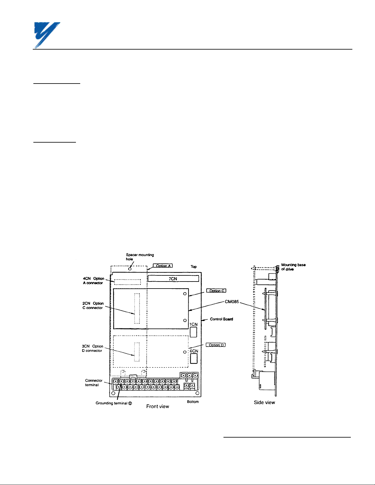
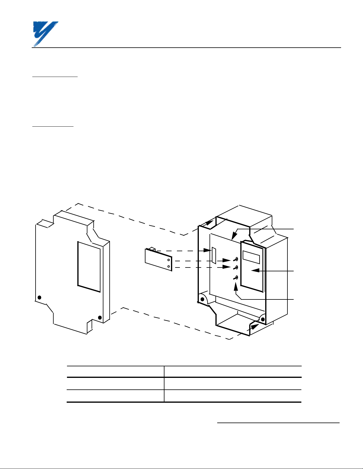
A4. See Figure A1. Install the option on the Main Control Board, 1PCB, and ensure 2CN is properly connected.
Make sure Electrostatic procedure is followed.
Figure A1. Installation of Analog Speed Reference (AI-14B) in GPD 515/G5
Yaskawa Electric America, Inc-www.drives.com
02Y00025-0296 Page 2 OF 14
REL. 08/23/91
Page 3
ANALOG SPEED REFERENCE
(BIPOLAR) (AI-14B) MODEL DS387
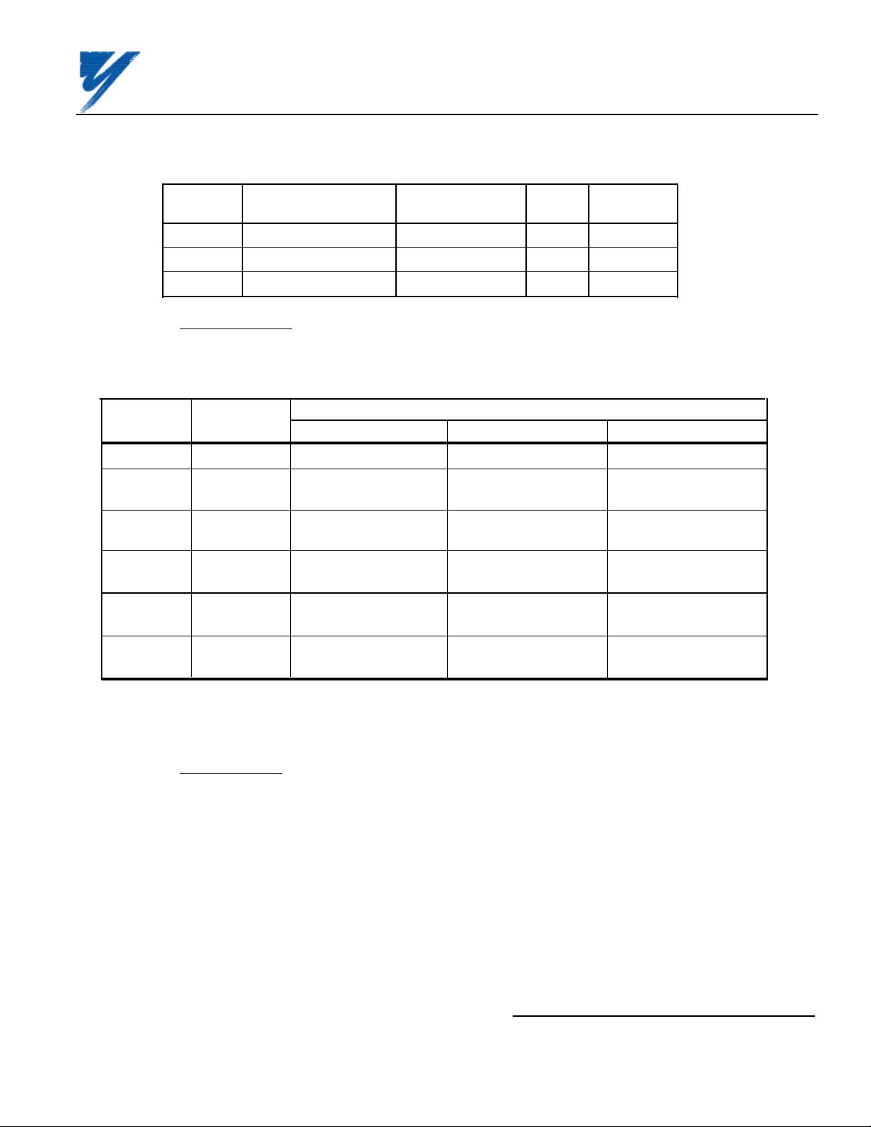
Table A1. AI-14B Specifications in GPD 515
Parameter Value
Input Signal Level 0 to ±10V DC (Input Impedance: 20kΩ)
0 to 20mA (input impedance : 500Ω)
Input Resolution Voltage: 13 bits (1/8192) plus sign (polarity)
Current: 1/6554
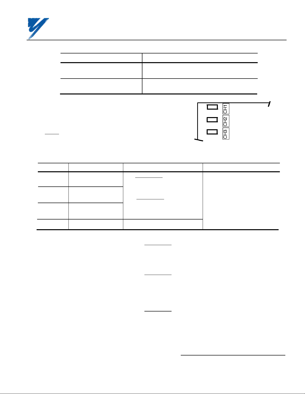
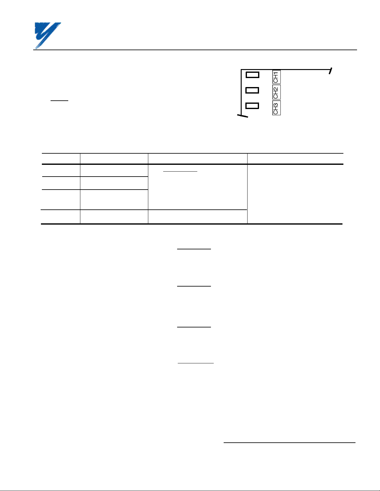
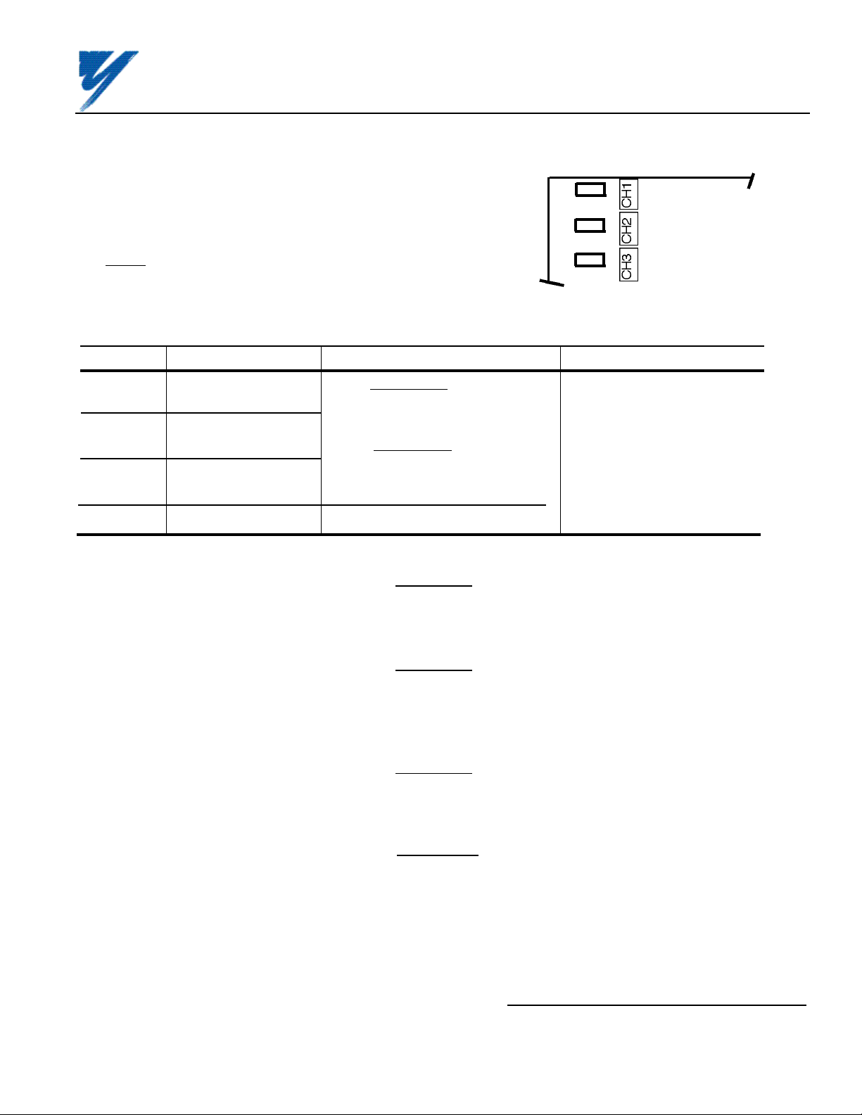
A5. Determine whether a voltage or current
signal will be inputted on each of the channels of
the AI–14B board, and set selection jumpers
accordingly (see Figure A2).
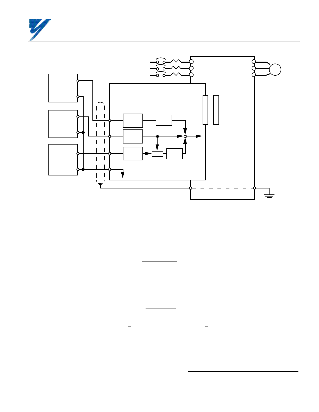
A6. Wiring. See Figure A3 for Analog Speed
Reference connections. See Table A2 for terminal
functions.
ALL JUMPERS
(SHORTING
PLUGS) SHOWN
IN POSITION
FOR CURRENT
INPUT
• • •
V C
• • •
V C
• • •
V C
Figure A2. Voltage/Current Selection on AI-14B
Table A2. Terminal Functions of AI-14B
Terminal Function Signal Level Notes
TC1 Analog voltage/current Voltage Input: — Input Resolution:
input Input voltage: 0 to ±10V/0 to ±100% Voltage: 1/8192 (13 bits) plus
Input impedance: 20K Ω sign (polarity)
TC2 Analog voltage/current Current: 1/6554
input Current Input:
Input current: 0 to 20mA/0 to ±100% — Signal Linearity: ±0.1%
TC3 Analog voltage/current Input impedance: 500 Ω
input — Terminal screws are metric
size M3.
TC4 Signal common 0V
CAUTION
PART OF
AI-14B
BOARD
KEEP ANALOG SPEED REF. (I.E. CONTROL CIRCUIT) WIRING
SEPARATE FROM MAIN CIRCUIT INPUT/OUTPUT WIRING.
CAUTION
TO PREVENT ERRONEOUS OPERATION CAUSED BY NOISE
INTERFERENCE, USE SHIELDED CABLE FOR CONTROL WIRING,
AND LIMIT DISTANCE TO 10M (33 FEET) OR LESS.
CAUTION
IF ANY OF THE CONTROL SIGNAL INPUT TERMINALS (TC1 THRU
TC3) ARE NOT USED, JUMPER THEM TO 0V TERMINAL (TC4).
Yaskawa Electric America, Inc-www.drives.com
02Y00025-0296 Page 3 OF 14
REL. 08/23/91
Page 4
ANALOG SPEED REFERENCE
(BIPOLAR) (AI-14B) MODEL DS387
IMPORTANT
Because the analog speed reference is converted by 1/16384 resolution, the
voltage source accuracy of the analog speed reference source must be considered. To ensure speed control accuracy, use a high precision power supply for
the voltage source.
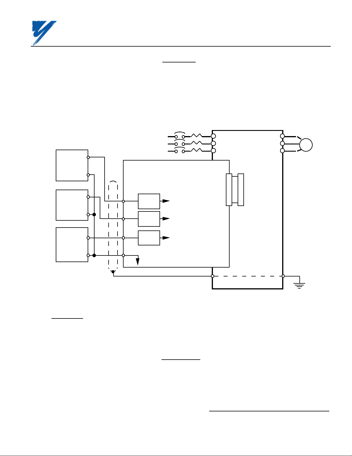
Route wires from the drive and connect to the peripheral device. Refer to "Electrical Installation" in the drive
technical manual for further information on use of shielded cable.
HIGH ACCURACY
VOLTAGE / CURRENT
DEVICES
0-±10V
or 0-20mA
0V
0-±10V
or 0-20mA
0V
0-±10V
or 0-20mA
0V
TC1
TC2
TC3
TC4
SHIELD
AI-14B BOARD
14 BIT
A/D
14 BIT
A/D
14 BIT
A/D
0V
MCCB
SEE
FIGURE A4
FOR BLOCK
DIAGRAM
L1
L2
L3
2CN
12
GPD
515
2CN
T1
T2
T3
MOTOR
I M
E
Figure A3. Interconnection for Analog Speed Reference (AI-14B) Circuit in GPD 515
A7. Adjustments.
There are no adjustments to be made on the Analog Speed Reference option; however, the GPD 515 will have to
be reprogrammed for the input requirement(s) of the remote device and the reversing or non-reversing
requirement of the specific application.
WARNING
IF THE APPLICATION REQUIRES THAT REVERSE MOTOR
ROTATION BE PROHIBITED, PARAMETER b1-04 MUST BE SET
TO " 1 " SO THAT THE MOTOR WILL STOP ANY TIME
POLARITY OF THE SPEED REFERENCE GOES NEGATIVE.
Yaskawa Electric America, Inc-www.drives.com
02Y00025-0296 Page 4 OF 14
REL. 08/23/91
Page 5
Channel 1 (TC1)
Channel 2 (TC2)
Channel 3 (TC3)
F2-01 = 0
Three Channel
Individual
14 Bit
A/D
14 Bit
A/D
14 Bit
A/D
H3-01 Sig.
010-10V
±10V
H3-01 Sig.
0
0-10V
1
±10V
2
4-20mA
H3-01 Sig.
010-10V
±10V
U1-15
U1-16
U1-17
ANALOG SPEED REFERENCE
(BIPOLAR) (AI-14B) MODEL DS387
–
–
–
100%
+
100%
+
100%
+
Bias
H3-03
X
Bias
H3-11
X
Bias
H3-07
X
+
+
+
Gain
H3-02
X
Automatic Speed
Reference
+
Gain
H3-10
X
Select Via
H3-09
+
Gain
H3-06
X
Select Via
H3-05
+
F2-01 = 1
Three Channel
Addition
1/10
+
+
+
1/10
X
–
100%
+
H3-03
X
H3-02
+
X
Option PCB
Reference
+
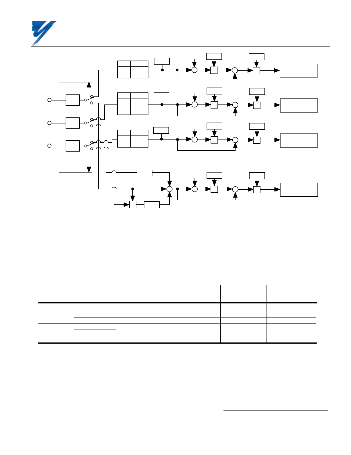
Figure A4. AI-14B Block Diagram
As Figure A4 shows, there are two possible modes of operation for the AI-14B board when it is installed in the
GPD 515. These modes are selected by drive parameter F2-01 (AI-14B Input Selection). When F2-01 is set to
" 0 ", 3-channel individual mode is selected. In this mode the AI-14B replaces the analog inputs on the GPD 515
main control board (see Table A3). When F2-01 is set to " 1 ", 3-channel addition mode is selected. In this mode
the AI-14B adds the three channels together. This new “added” signal replaces the automatic speed reference
input (terminal 13) when reference source is set to "Option PCB" ( b1-01 = 3).
Table A3. AI-14B Configuration in the GPD 515
Mode AI-14B "Equivalent" Terminal on "Gain" "Offset"
Terminal GPD 515 Control Board Parameter *** Parameter ***
3-Channel
Individual *
3-Channel
Addition **
* When using the 3-Channel Individual mode, Channel 1 (TC1) becomes the automatic speed
TC1 13 H3-02 H3-03
TC2 14 H3-06 H3-07
TC3 16 H3-10 H3-11
TC1
TC2 13 H3-02 H3-03
TC3
reference, Channel 2 (TC2) can be configured using parameter H3-09 (see section 5.22 of the
GPD 515 technical manual), and Channel 3 (TC3) can be configured using parameter H3-05.
** In order to use the 3-Channel Addition mode, parameter b1-01 (Reference Source) must be
set to " 3 " (Option Board).
Frequency Reference = TC1 +
TC2 +TC3 x TC1
10 10
*** See Figure A5.
Yaskawa Electric America, Inc-www.drives.com
02Y00025-0296 Page 5 OF 14
REL. 08/23/91
Page 6

ANALOG SPEED REFERENCE
(BIPOLAR) (AI-14B) MODEL DS387
H3-02
H3-03
(+)
FREQ.
CMD
(%)
H3-03
(–)
Figure A5. Gain and Bias Adjustments for GPD 515
(shown for Channel 1 (TC1) of the AI-14B option board)
A8. Reinstall and secure the drive cover.
GAIN
0
0V
BIAS
10V
SPEED
REF.
INPUT
A9. Place this instruction sheet with the drive technical manual.
THIS COMPLETES INSTALLATION OF THIS OPTION IN THE GPD 515.
Yaskawa Electric America, Inc- www.drives.com
02Y00025-0296 Page 6 OF 14
REL. 08/23/91
Page 7
ANALOG SPEED REFERENCE
(BIPOLAR) (AI-14B) MODEL DS387
Section B: Installation in a VCD 703
INTRODUCTION
When installed, this option allows the user to interface three separate high resolution voltage signals (13-bit plus
sign). These signals can be programmed for speed reference, torque reference, torque limit, or torque comp.
Gain for the input signals is adjusted by using drive constants. Polarity (sign) of the speed reference controls
direction of motor rotation.
INSTALLATION
B1. Disconnect all electrical power to drive.
B2. Remove drive front cover. Check that CHARGE indicator lamp inside drive is off.
B3. Verify voltage has been disconnected by using a voltmeter to check for voltage at incoming power terminals
(L1, L2, L3).
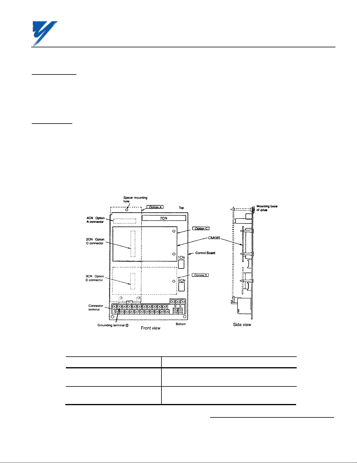
B4. See Figure B1. Install the option on the Main Control Board, 1PCB, and ensure 2CN is properly connected.
Make sure Electrostatic procedure is followed.
FRONT
COVER
2CN
AI-14B
OPTION
BOARD
Figure B1. Installation of Analog Speed Reference (AI-14B) in VCD 703
Table B1. AI-14B Specifications in VCD 703
Parameter Value
Input Signal Level 0 to ±10V DC (Input Impedance: 20kΩ)
Input Resolution Voltage: 13 bits (1/8192) plus sign (polarity)
MAIN
CONTROL
BOARD
DIGITAL
OPERATOR
PLASTIC
STANDOFFS
ON MAIN
BOARD
Yaskawa Electric America, Inc-www.drives.com
02Y00025-0296 Page 7 OF 14
REL. 08/23/91
Page 8
ANALOG SPEED REFERENCE
(BIPOLAR) (AI-14B) MODEL DS387
B5. For VCD 703, all input selection jumpers on
the AI–14B board must be set to "V" (see Figure
B2).
B6. Wiring. See Figure B3 for Analog Speed
Reference connections. See Table B2 for
terminal functions.
Table B2. Terminal Functions of AI-14B
Terminal Function Signal Level Notes
TC1 Analog voltage input Voltage Input: — Input Resolution:
Input voltage: 0 to ±10V/0 to ±100% Voltage: 1/8192 (13 bits) plus
TC2 Analog voltage input Input impedance: 20K Ω sign (polarity)
TC3 Analog voltage input — Signal Linearity: ±0.1%
TC4 Signal common 0V size M3.
ALL JUMPERS
(SHORTING
PLUGS) SHOWN
IN POSITION
FOR VOLTAGE
INPUT
Figure B2. Voltage/Current Selection on AI-14B
• • •
V C
• • •
V C
• • •
V C
— Terminal screws are metric
CAUTION
PART OF
AI-14B
BOARD
KEEP ANALOG SPEED REF. (I.E. CONTROL CIRCUIT) WIRING
SEPRATE FROM MAIN CIRCUIT INPUT/OUTPUT WIRING.
CAUTION
TO PREVENT ERRONEOUS OPERATION CAUSED BY NOISE
INTERFENCE, USE SHIELDED CABLE FOR CONTROL WIRING, AND
LIMIT DISTANCE TO 10M (33 FEET) OR LESS.
CAUTION
IF ANY OF THE CONTROL SIGNAL INPUT TERMINALS (TC1 THRU TC3)
ARE NOT USED, JUMPER THEM TO 0V TERMINAL (TC4).
IMPORTANT
Because the analog speed reference is converted by 1/16384 resolution, the voltage
source accuracy of the analog speed reference source must be con-sidered. To
ensure speed control accuracy, use a high precision power supply for the voltage
source.
Route wires from the drive and connect to the peripheral device. Refer to "Electrical Installation" in the drive
technical manual for further information on use of shielded cable.
Yaskawa Electric America, Inc-www.drives.com
02Y00025-0296 Page 8 OF 14
REL. 08/23/91
Page 9

HIGH ACCURACY
DETERMINED BY
SETTING
OF Sn-25
(SEE TABLE B4)
ANALOG SPEED REFERENCE
(BIPOLAR) (AI-14B) MODEL DS387
VOLTAGE
DEVICES
0-±10V
0V
0-±10V
TC1
1000
pF
MCCB
AI-14B BOARD
10K
500
20K
20K
1 µF
L1
L2
L3
2CN
VCD
703
2CN
T1
T2
T3
MOTOR
I M
*
*
VC
SIGNAL
FUNCTIONS
12 (OR 32)
E
0V
TC2
0-±10V
0V
Figure B3. Interconnection for Analog Speed Reference (AI-14B) Circuit in VCD 703
B7. Adjustments
There are no adjustments to be made on the Analog Speed Reference option; however, the VCD 703 will have to be
reprogrammed for the input requirement of the remote device and the reversing or non-reversing requirement of the
specific application.
TC3
TC4
0V
SHIELD
TC2 AND TC3 INPUT CIRCUITS
*
ARE IDENTICAL TO TC1.
WARNING
IF THE APPLICATION REQUIRES THAT REVERSE MOTOR
ROTATION BE PROHIBITED, Sn-05 MUST BE SET TO X X 1 X
SO THAT THE MOTOR WILL STOP ANY TIME POLARITY OF THE
SPEED REFERENCE GOES NEGATIVE.
IMPORTANT
For the Analog Speed Reference circuit to function properly, system constant Sn-04
must be set to XXX 0 and Sn-08 must be set to XXX 0 (input to AI-14B replaces
auto speed reference signal).
(1) GAIN: Adjustment of the gain of the speed or torque reference commands is done by changing
the associated VCD 703 constants; see Table B3.
Yaskawa Electric America, Inc-www.drives.com
02Y00025-0296 Page 9 OF 14
REL. 08/23/91
Page 10
ANALOG SPEED REFERENCE
(BIPOLAR) (AI-14B) MODEL DS387
Table B3. Setting Gain of Speed Reference Commands
Constant Setting Incre- Factory
No. Description Range ment Setting
Cn-30 AI-14B Chan. 1 Gain 0.0 to 1000.0 (%) 0.1 100.0
Cn-31 AI-14B Chan. 2 Gain 0.0 to 1000.0 (%) 0.1 100.0
Cn-32 AI-14B Chan. 3 Gain 0.0 to 1000.0 (%) 0.1 100.0
(2) Reference Inputs: The AI-14B can be programmed for either speed mode references or torque
mode references by programming Sn-25; see Table B4.
Table B4. Selecting Speed or Torque Mode
SET CONTROL
VALUE MODE *
0000 ASR I Speed Reference Not Used Not Used
0001 ASR II Speed Reference Speed Ref. Torque
0010 ASR III Speed Reference Fwd. Torque Limit Rev. Torque Limit
0011 ASR IV Speed Reference Torque Limit Torque
1000 ATR I Speed Limit Torque Torque
1001 ATR II Not Used Torque Not Used
* ASR : Speed control mode; ATR : Torque control mode
NOTE: To increase control accuracy, use a high-accuracy, stabilized power supply.
(3) Monitor Display: Inputs to the AI-14B can be monitored by the VCD 703 by using the Un-XX
constants.
Un-36 = CH1 input voltage (V) 10V / 10V
Un-37 = CH2 input voltage (V) 10V / 10V
Un-38 = CH3 input voltage (V) 10V / 10V
CH 1 CH 2 CH 3
AI-14B INPUTS
Trim Compensation
(TLF) (TLR)
(TLF, TLR) Compensation
Reference Compensation
Reference
B8. Reinstall and secure drive cover.
B9. Place this instruction sheet with the drive technical manual.
THIS COMPLETES INSTALLATION OF THIS OPTION IN THE VCD 703.
Yaskawa Electric America, Inc-www.drives.com
02Y00025-0296 Page 10 OF 14
REL. 08/23/91
Page 11
ANALOG SPEED REFERENCE
(BIPOLAR) (AI-14B) MODEL DS387
Section C: Installation in a GPD 503
INTRODUCTION
When installed, this option allows the user to interface three separate high resolution analog input signals, each of
which may be either current or voltage (13-bit plus sign). These signals are added by the AI-14B board and the
result is applied to the drive as a high accuracy 0-±10V frequency reference. Gain and bias for the input reference
is adjusted by using drive constants. Polarity (sign) of the speed reference controls direction of motor rotation.
INSTALLATION
C1. Disconnect all electrical power to drive.
C2. Remove drive front cover. Check that CHARGE indicator lamp inside drive is off.
C3. Verify voltage has been disconnected by using a voltmeter to check for voltage at incoming power terminals
(L1, L2, L3).
C4. See Figure C1. Install the option on the Main Control Board, 1PCB, and ensure 2CN is properly connected.
Make sure Electrostatic procedure is followed.
Figure C1. Installation of Analog Speed Reference (AI-14B) in GPD 503
Table C1. AI-14B Specifications in GPD 503
Parameter Value
Input Signal Level 0 to ±10V DC (Input Impedance: 20kΩ)
40 to 20mA (input impedance : 500Ω)
Input Resolution Voltage: 13 bits (1/8192) plus sign (polarity)
Current: 1/6554
Yaskawa Electric America, Inc-www.drives.com
02Y00025-0296 Page 11 OF 14
REL. 08/23/91
Page 12
ANALOG SPEED REFERENCE
(BIPOLAR) (AI-14B) MODEL DS387
C5. Determine whether a voltage or current
signal will be inputted on each of the channels of
the AI–14B board, and set selection jumpers
accordingly (see Figure C2).
6. Wiring. See Figure C3 for Analog Speed
Reference connections. See Table C2 for
terminal functions.
ALL JUMPERS
(SHORTING
PLUGS) SHOWN
IN POSITION
FOR CURRENT
INPUT
• • •
V C
• • •
V C
• • •
V C
Figure C2. Voltage/Current Selection on AI-14B
Table C2. Terminal Functions of AI-14B
Terminal Function Signal Level Notes
TC1 Analog voltage/current Voltage Input: — Input Resolution:
input Input voltage: 0 to ±10V/0 to ±100% Voltage: 1/8192 (13 bits) plus
Input impedance: 20K Ω sign (polarity)
TC2 Analog voltage/current Current: 1/6554
input Current Input:
Input current: 4 to 20mA/0 to ±100% — Signal Linearity: ±0.1%
TC3 Analog voltage/current Input impedance: 500 Ω
input — Terminal screws are metric
size M3.
TC4 Signal common 0V
CAUTION
PART OF
AI-14B
BOARD
KEEP ANALOG SPEED REF. (I.E. CONTROL CIRCUIT) WIRING
SEPRATE FROM MAIN CIRCUIT INPUT/OUTPUT WIRING.
CAUTION
TO PREVENT ERRONEOUS OPERATION CAUSED BY NOISE
INTERFERENCE, USE SHIELDED CABLE FOR CONTROL WIRING,
AND LIMIT DISTANCE TO 10M (33 FEET) OR LESS.
CAUTION
IF ANY OF THE CONTROL SIGNAL INPUT TERMINALS (TC1 THRU
TC3) ARE NOT USED, JUMPER THEM TO 0V TERMINAL (TC4).
IMPORTANT
Because the analog speed reference is converted by 1/16384 resolution, the
voltage source accuracy of the analog speed reference source must be considered. To ensure speed control accuracy, use a high precision power supply for
the voltage source.
Route wires from the drive and connect to the peripheral device. Refer to "Electrical Installation" in the drive
technical manual for further information on use of shielded cable.
Yaskawa Electric America, Inc-www.drives.com
02Y00025-0296 Page 12 OF 14
REL. 08/23/91
Page 13
ANALOG SPEED REFERENCE
(BIPOLAR) (AI-14B) MODEL DS387
HIGH ACCURACY
VOLTAGE / CURRENT
DEVICES
0-±10V
or 4-20mA
0V
0-±10V
or 4-20mA
0V
0-±10V
or 4-20mA
0V
TC2
TC1
TC3
TC4
SHIELD
AI-14B BOARD
14 BIT
A/D
14 BIT
A/D
14 BIT
A/D
0V
MCCB
1 / 10
X
1 / 10
MOTOR
L1
L2
L3
T1
T2
T3
I M
GPD
503
2CN
+
+
FREQ.
+
REF
12
2CN
E
Figure C3. Interconnection for Analog Speed Reference (AI-14B) Circuit in GPD 503
C7. Adjustments.
There are no adjustments to be made on the Analog Speed Reference option; however, the GPD 503 will have to
be reprogrammed for the input requirement of the remote device and the reversing or non-reversing requirement
of the specific application.
WARNING
IF THE APPLICATION REQUIRES THAT REVERSE MOTOR
ROTATION BE PROHIBITED, Sn-25 MUST BE SET TO X X X 1
SO THAT THE MOTOR WILL STOP ANY TIME POLARITY OF
THE SPEED REFERENCE GOES NEGATIVE.
IMPORTANT
For the Analog Speed Reference circuit to function properly, system constant
Sn-04 must be set to XXX0 and Sn-08 must be set to XXX0 (input to AI-14B
replaces auto speed reference signal).
Adjustment of the bias and gain of the frequency command are done by changing the associated GPD 503
constants; see Figure C4 and Table C3.
Yaskawa Electric America, Inc-www.drives.com
02Y00025-0296 Page 13 OF 14
REL. 08/23/91
Page 14

ANALOG SPEED REFERENCE
(BIPOLAR) (AI-14B) MODEL DS387
Channel 2 (TC2)
0 to ±10V
Channel 1 (TC1)
0 to ±10V
Channel 3 (TC3)
0 to ±10V
Cn-46
x
100
Cn-45
x
100
Cn-47
x x
100
( AI-14B )
1/10
Frequency Reference (%)
bn-05
+
+
+
bn-06
10V
Input Voltage
Sn-25
0000
0001
Frequency
Reference
+ / – input
+ input only
Internal
Frequency
Command
( GPD 503 )
Figure 5. Frequency Command Gain and Bias Adjustments
Table 3. Setting Bias and Gain of Frequency Command
LHP GPD 503 HHP GPD 503
Constant Setting Incre- Factory Setting Incre- Factory
No. Description Range ment Setting Range ment Setting
bn-05 Freq. Reference Gain 0.0 to 1000.0 (%) 1.0 100.0 0.0 to 1000.0 (%) 0.1 100.0
bn-06 Freq. Reference Bias -100 to 100 (%) 1 0 –100.0 to 100.0 (%) 0.1 0.0
Cn-45 AI-14B Chan. 1 Gain Constant not used; Fixed gain of 100% 0.0 to 1000.0 (%) 0.1 100.0
Cn-46 AI-14B Chan. 2 Gain Constant not used; Fixed gain of 10% 0.0 to 1000.0 (%) 0.1 10.0
Cn-47 AI-14B Chan. 3 Gain Constant not used; Fixed gain of 10% 0.0 to 1000.0 (%) 0.1 10.0
EXAMPLE:
With all channel inputs at maximum, the frequency command (displayed on Digital
Monitor) is only 59 Hz. To obtain 60 Hz maximum frequency command, the required
correction factor (Gain) is 60 Hz/59 Hz = 1.01695 = 101.7%. Therefore, program
bn-05 setting to 101.7 (%).
C8. Reinstall and secure drive cover.
C9. Place this instruction sheet with the drive technical manual.
THIS COMPLETES INSTALLATION OF THIS OPTION IN THE GPD 503.
Yaskawa Electric America, Inc-www.drives.com
02Y00025-0296 Page 14 OF 14
REL. 08/23/91
 Loading...