

Yamaha YP400T Service Manual

YP400T
SERVICE MANUAL
LIT-11616-18-38 5RU-28197-10
EAS00001
©2004 by Yamaha Motor Corporation, U.S.A.
YP400T
SERVICE MANUAL
First edition, June 2004
All rights reserved.
Any reproduction or unauthorized use
without the written permission of
Yamaha Motor Corporation, U.S.A.
is expressly prohibited.
Printed in U.S.A.
P/N LIT-11616-18-38
EAS00003
NOTICE
This manual was produced by the Yamaha Motor Company, Ltd. primarily for use by Yamaha dealers and their qualified mechanics. It is not possible to include all the knowledge of a mechanic in
one manual. Therefore, anyone who uses this book to perform maintenance and repairs on Yamaha
vehicles should have a basic understanding of mechanics and the techniques to repair these types
of vehicles. Repair and maintenance work attempted by anyone without this knowledge is likely to
render the vehicle unsafe and unfit for use.
This model has been designed and manufactured to perform within certain specifications in regard
to performance and emissions. Proper service with the correct tools is necessary to ensure that the
vehicle will operate as designed. If there is any question about a service procedure, it is imperative
that you contact a Yamaha dealer for any service information changes that apply to this model. This
policy is intended to provide the customer with the most satisfaction from his vehicle and to conform
to federal environmental quality objectives.
Yamaha Motor Company, Ltd. is continually striving to improve all of its models. Modifications and
significant changes in specifications or procedures will be forwarded to all authorized Yamaha dealers and will appear in future editions of this manual where applicable.
NOTE:
_
• This Service Manual contains information regarding periodic maintenance to the emission control
system. Please read this material carefully.
• Designs and specifications are subject to change without notice.
EAS00005
IMPORTANT MANUAL INFORMATION
Particularly important information is distinguished in this manual by the following.
The Safety Alert Symbol means ATTENTION! BECOME ALERT! YOUR
SAFETY IS INVOLVED!
WARNING
CAUTION:
NOTE:
Failure to follow WARNING instructions could result in severe injury or death
the scooter operator, a bystander or a person checking or repairing the scooter.
A CAUTION indicates special precautions that must be taken to avoid damage
to the scooter.
A NOTE provides key information to make procedures easier or clearer.
to
EAS00007
HOW TO USE THIS MANUAL
This manual is intended as a handy, easy-to-read reference book for the mechanic. Comprehensive
explanations of all installation, removal, disassembly, assembly, repair and check procedures are
laid out with the individual steps in sequential order.
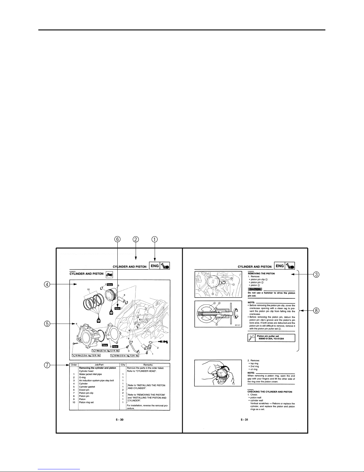
1
The manual is divided into chapters. An abbreviation and symbol in the upper right corner of
each page indicate the current chapter.
Refer to “SYMBOLS”.
2
Each chapter is divided into sections. The current section title is shown at the top of each page,
except in Chapter 3 (“PERIODIC CHECKS AND ADJUSTMENTS”), where the sub-section
title(s) appears.
3
Sub-section titles appear in smaller print than the section title.
4
To help identify parts and clarify procedure steps, there are exploded diagrams at the start of
each removal and disassembly section.
5
Numbers are given in the order of the jobs in the exploded diagram. A circled number indicates a
disassembly step.
6
Symbols indicate parts to be lubricated or replaced.
Refer to “SYMBOLS”.
7
A job instruction chart accompanies the exploded diagram, providing the order of jobs, names of
parts, notes in jobs, etc.
8
Jobs requiring more information (such as special tools and technical data) are described sequentially.
12
GEN
SPEC
INFO
34
CHK
CHAS
ADJ
56
ENG
78
COOL
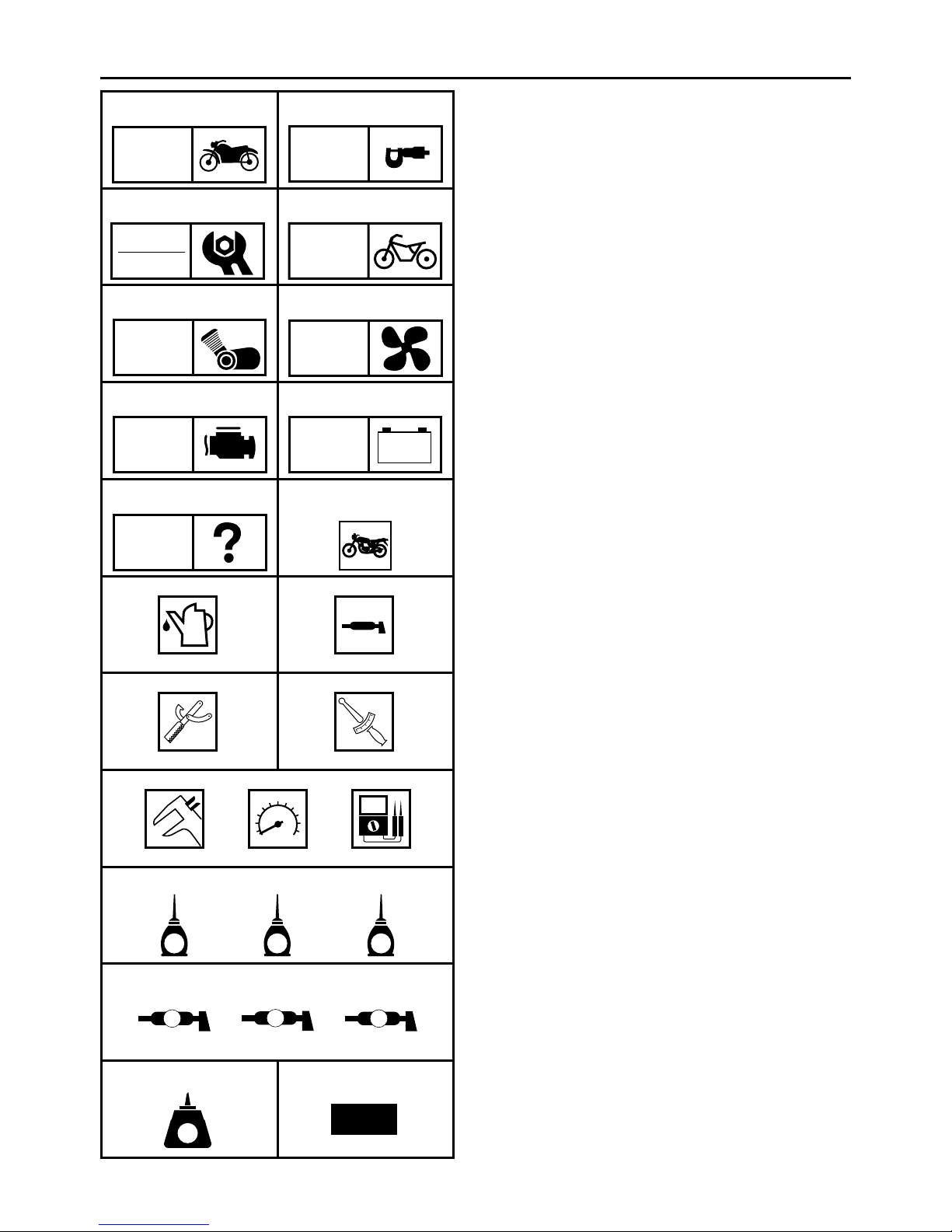
EAS00008
SYMBOLS
The following symbols are not relevant to
every vehicle.
Symbols 1 to 9 indicate the subject of each
chapter.
General information
1
Specifications
2
Periodic checks and adjustments
3
Chassis
4
Engine
5
Cooling system
6
Fuel injection system
7
Electrical system
8
Troubleshooting
9
FI
90
ELEC
–+
TRBL
SHTG
AB
CD
T
.
R
.
EFG
HIJ
LS
G
M
M
E
KLM
B
Symbols 0 to G indicate the following.
Serviceable with engine mounted
0
Filling fluid
A
Lubricant
B
Special tool
C
Tightening torque
D
Wear limit, clearance
E
Engine speed
F
Electrical data
G
Symbols H to M in the exploded diagrams
indicate the types of lubricants and lubrication
points.
Engine oil
H
Gear oil
I
Molybdenum-disulfide oil
J
Wheel-bearing grease
K
Lithium-soap-based grease
L
Molybdenum-disulfide grease
M
NO
LT
New
Symbols N to O in the exploded diagrams
indicate the following.
®
Apply locking agent (LOCTITE
N
Replace the part
O
)
EAS00010
TABLE OF CONTENTS
GENERAL INFORMATION
SPECIFICATIONS
PERIODIC CHECKS AND
ADJUSTMENTS
CHASSIS
ENGINE
GEN
INFO
SPEC
CHK
ADJ
CHAS
ENG
1
2
3
4
5
COOLING SYSTEM
FUEL INJECTION SYSTEM
ELECTRICAL SYSTEM
TROUBLESHOOTING
COOL
FI
– +
ELEC
TRBL
SHTG
6
7
8
9

CONTENTS
CHAPTER 1
GENERAL INFORMATION
SCOOTER IDENTIFICATION
VEHICLE IDENTIFICATION NUMBER .....................................................1-1
MODEL LABEL..........................................................................................1-1
FEATURES
OUTLINE OF THE FI SYSTEM.................................................................1-2
FI SYSTEM................................................................................................ 1-3
INSTRUMENT FUNCTIONS .....................................................................1-4
IMPORTANT INFORMATION
PREPARATION FOR REMOVAL AND DISASSEMBLY......................... 1-10
REPLACEMENT PARTS.........................................................................1-10
GASKETS, OIL SEALS AND O-RINGS .................................................. 1-10
LOCK WASHERS/PLATES AND COTTER PINS ...................................1-11
BEARINGS AND OIL SEALS ..................................................................1-11
CIRCLIPS ................................................................................................1-11
CHECKING THE CONNECTIONS
SPECIAL TOOLS
......................................................................................................1-2
..........................................................................................1-13
..........................................................................1-1
.......................................................................1-10
................................................................1-12
CHAPTER 2
SPECIFICATIONS
GENERAL SPECIFICATIONS
ENGINE SPECIFICATIONS
CHASSIS SPECIFICATIONS
ELECTRICAL SPECIFICATIONS
CONVERSION TABLE
GENERAL TIGHTENING TORQUE SPECIFICATIONS
..................................................................................2-17
........................................................................2-1
...........................................................................2-2
........................................................................2-10
.................................................................2-14
...............................2-17

TIGHTENING TORQUES ..............................................................................2-18
ENGINE TIGHTENING TORQUES.........................................................2-18
CHASSIS TIGHTENING TORQUES.......................................................2-21
LUBRICATION POINTS AND LUBRICANT TYPES ....................................2-23
ENGINE LUBRICATION POINTS AND LUBRICANT TYPES ................2-23
CHASSIS LUBRICATION POINTS AND LUBRICANT TYPES .............2-25
COOLING SYSTEM DIAGRAMS ..................................................................2-26
CABLE ROUTING .........................................................................................2-28
CHAPTER 3
PERIODIC CHECKS AND ADJUSTMENTS
INTRODUCTION..............................................................................................3-1
PERIODIC MAINTENANCE CHART FOR THE EMISSION
CONTROL SYSTEM........................................................................................3-1
GENERAL MAINTENANCE AND LUBRICATION CHART ............................ 3-2
COWLING AND COVERS...............................................................................3-4
PASSENGER SEAT AND SIDE COVERS................................................ 3-4
RIDER SEAT AND STORAGE BOX ......................................................... 3-5
SIDE COVER MOULDINGS AND FOOTREST BOARDS ........................ 3-7
FRONT COWLING ....................................................................................3-8
AIR FILTER CASES ......................................................................................3-10

ENGINE .........................................................................................................3-11
ADJUSTING THE VALVE CLEARANCE ................................................3-11
ADJUSTING THE EXHAUST GAS VOLUME ......................................... 3-16
CHECKING THE ENGINE IDLING SPEED ............................................3-17
ADJUSTING THE THROTTLE CABLE FREE PLAY ..............................3-18
CHECKING THE SPARK PLUG .............................................................3-18
CHECKING THE IGNITION TIMING.......................................................3-20
MEASURING THE COMPRESSION PRESSURE.................................. 3-21
CHECKING THE ENGINE OIL LEVEL.................................................... 3-23
CHANGING THE ENGINE OIL ...............................................................3-24
CHANGING THE TRANSMISSION OIL..................................................3-27
REPLACING THE AIR FILTER ELEMENTS...........................................3-28
CLEANING THE V-BELT CASE AIR FILTER ELEMENT ....................... 3-29
CHECKING THE THROTTLE BODY JOINT AND
INTAKE MANIFOLD ............................................................................... 3-30
CHECKING THE FUEL HOSE ................................................................3-30
CHECKING THE BREATHER HOSES ................................................... 3-31
CHECKING THE EXHAUST SYSTEM.................................................... 3-32
CHECKING THE COOLANT LEVEL.......................................................3-32
CHECKING THE COOLING SYSTEM ....................................................3-33
CHANGING THE COOLANT...................................................................3-34
CHASSIS .......................................................................................................3-37
ADJUSTING THE REAR BRAKE LOCK LEVER CABLE .......................3-37
CHECKING THE BRAKE FLUID LEVEL.................................................3-38
CHECKING THE FRONT AND REAR BRAKE PADS ............................3-39
CHECKING THE FRONT AND REAR BRAKE HOSES.......................... 3-39
BLEEDING THE HYDRAULIC BRAKE SYSTEM ...................................3-40
CHECKING AND ADJUSTING THE STEERING HEAD .........................3-41
CHECKING THE FRONT FORK .............................................................3-43
CHECKING THE TIRES..........................................................................3-44
CHECKING THE WHEELS .....................................................................3-47
CHECKING AND LUBRICATING THE CABLES ....................................3-47
LUBRICATING THE LEVERS .................................................................3-48
LUBRICATING THE SIDESTAND...........................................................3-48
LUBRICATING THE CENTERSTAND .................................................... 3-48
ELECTRICAL SYSTEM.................................................................................3-49
CHECKING AND CHARGING THE BATTERY.......................................3-49
CHECKING THE FUSES ........................................................................3-54
REPLACING THE HEADLIGHT BULBS ................................................. 3-56
ADJUSTING THE HEADLIGHT BEAMS................................................. 3-58

CHAPTER 4
CHASSIS
FRONT WHEEL AND BRAKE DISC
REMOVING THE FRONT WHEEL............................................................4-3
CHECKING THE FRONT WHEEL ............................................................4-3
CHECKING THE BRAKE DISCS ..............................................................4-4
INSTALLING THE FRONT WHEEL ..........................................................4-6
ADJUSTING THE FRONT WHEEL STATIC BALANCE ........................... 4-7
REAR WHEEL AND BRAKE DISC
REMOVING THE REAR WHEEL ............................................................4-10
CHECKING THE REAR WHEEL.............................................................4-10
ADJUSTING THE REAR WHEEL STATIC BALANCE............................ 4-10
FRONT AND REAR BRAKES
FRONT BRAKE PADS ............................................................................4-11
REAR BRAKE PADS...............................................................................4-12
REPLACING THE FRONT BRAKE PADS .............................................. 4-13
REPLACING THE REAR BRAKE PADS................................................. 4-15
FRONT BRAKE MASTER CYLINDER....................................................4-18
REAR BRAKE MASTER CYLINDER ...................................................... 4-21
DISASSEMBLING THE FRONT BRAKE MASTER CYLINDER ............. 4-24
DISASSEMBLING THE REAR BRAKE MASTER CYLINDER................ 4-24
CHECKING THE FRONT AND REAR BRAKE
MASTER CYLINDERS ...........................................................................4-25
ASSEMBLING AND INSTALLING THE FRONT BRAKE
MASTER CYLINDER .............................................................................4-26
ASSEMBLING AND INSTALLING THE REAR BRAKE
MASTER CYLINDER .............................................................................4-28
FRONT BRAKE CALIPER.......................................................................4-31
REAR BRAKE CALIPER .........................................................................4-33
DISASSEMBLING THE FRONT BRAKE CALIPER ................................4-36
DISASSEMBLING THE REAR BRAKE CALIPER ..................................4-36
CHECKING THE FRONT AND REAR BRAKE CALIPERS ....................4-37
ASSEMBLING AND INSTALLING THE FRONT BRAKE CALIPER .......4-39
ASSEMBLING AND INSTALLING THE REAR BRAKE CALIPER.......... 4-41
.......................................................................4-11
...............................................................4-1
.................................................................4-9
FRONT FORK
REMOVING THE FRONT FORK LEGS..................................................4-48
DISASSEMBLING THE FRONT FORK LEGS ........................................4-48
CHECKING THE FRONT FORK LEGS ..................................................4-50
ASSEMBLING THE FRONT FORK LEGS ..............................................4-50
INSTALLING THE FRONT FORK LEGS ................................................4-53
HANDLEBAR
REMOVING THE HANDLEBAR..............................................................4-56
CHECKING THE HANDLEBAR ..............................................................4-56
INSTALLING THE HANDLEBAR ............................................................4-56
................................................................................................4-44
................................................................................................4-54

STEERING HEAD..........................................................................................4-60
LOWER BRACKET .................................................................................4-60
REMOVING THE LOWER BRACKET.....................................................4-62
CHECKING THE STEERING HEAD .......................................................4-63
INSTALLING THE STEERING HEAD .....................................................4-64
REAR SHOCK ABSORBER ASSEMBLIES AND SWINGARM................... 4-65
REMOVING THE REAR SHOCK ABSORBER ASSEMBLIES ............... 4-67
CHECKING THE REAR SHOCK ABSORBER ASSEMBLIES................4-67
INSTALLING THE REAR SHOCK ABSORBER ASSEMBLIES..............4-67
REMOVING THE SWINGARM................................................................4-68
CHECKING THE SWINGARM ................................................................ 4-68
INSTALLING THE SWINGARM ..............................................................4-69
CHAPTER 5
ENGINE
ENGINE REMOVAL ........................................................................................5-1
LEADS, HOSES, EXHAUST PIPE AND MUFFLER .................................5-1
ENGINE.....................................................................................................5-3
INSTALLING THE ENGINE.......................................................................5-5
CAMSHAFTS...................................................................................................5-6
CYLINDER HEAD COVER........................................................................5-6
CAMSHAFTS ............................................................................................5-7
REMOVING THE CAMSHAFTS................................................................5-9
CHECKING THE CAMSHAFTS .............................................................. 5-10
CHECKING THE CAMSHAFT SPROCKETS .........................................5-12
CHECKING THE DECOMPRESSION SYSTEM..................................... 5-12
CHECKING THE TIMING CHAIN TENSIONER......................................5-13
INSTALLING THE CAMSHAFTS ............................................................5-13
CYLINDER HEAD..........................................................................................5-17
REMOVING THE CYLINDER HEAD.......................................................5-19
CHECKING THE CYLINDER HEAD ....................................................... 5-19
CHECKING THE TIMING CHAIN GUIDE (EXHAUST SIDE) .................5-20
INSTALLING THE CYLINDER HEAD ..................................................... 5-20
VALVES AND VALVE SPRINGS..................................................................5-21
REMOVING THE VALVES......................................................................5-22
CHECKING THE VALVES AND VALVE GUIDES ..................................5-23
CHECKING THE VALVE SEATS ............................................................5-25
CHECKING THE VALVE SPRINGS........................................................5-27
CHECKING THE VALVE LIFTERS .........................................................5-28
INSTALLING THE VALVES ....................................................................5-28

CYLINDER AND PISTON..............................................................................5-30
REMOVING THE PISTON ......................................................................5-31
CHECKING THE CYLINDER AND PISTON ........................................... 5-31
CHECKING THE PISTON RINGS...........................................................5-33
CHECKING THE PISTON PIN ................................................................5-34
INSTALLING THE PISTON AND CYLINDER ......................................... 5-34
BELT DRIVE..................................................................................................5-37
V-BELT CASE COVER ...........................................................................5-37
V-BELT AND PRIMARY/SECONDARY SHEAVE................................... 5-38
SECONDARY SHEAVE ..........................................................................5-40
REMOVING THE PRIMARY SHEAVE....................................................5-42
REMOVING THE SECONDARY SHEAVE AND V-BELT ....................... 5-42
DISASSEMBLING THE SECONDARY SHEAVE.................................... 5-43
CHECKING THE V-BELT........................................................................5-44
CHECKING THE V-BELT CASE AIR DUCTS......................................... 5-44
CHECKING THE PRIMARY SHEAVE ....................................................5-44
CHECKING THE PRIMARY SHEAVE WEIGHTS................................... 5-44
CHECKING THE SECONDARY SHEAVE ..............................................5-45
CHECKING THE CLUTCH SHOES ........................................................ 5-45
ASSEMBLING THE PRIMARY SHEAVE ................................................5-46
ASSEMBLING THE SECONDARY SHEAVE.......................................... 5-46
INSTALLING THE SECONDARY SHEAVE, V-BELT
AND PRIMARY SHEAVE ....................................................................... 5-47
STARTER CLUTCH AND GENERATOR......................................................5-49
GENERATOR ROTOR COVER AND STATOR COIL ............................5-49
STARTER CLUTCH AND GENERATOR................................................5-51
REMOVING THE GENERATOR .............................................................5-52
CHECKING THE STARTER CLUTCH ....................................................5-53
INSTALLING THE STARTER CLUTCH .................................................. 5-54
INSTALLING THE GENERATOR............................................................5-54
OIL PUMP......................................................................................................5-56
CHECKING THE OIL PUMP ...................................................................5-57
CHECKING THE OIL PUMP DRIVE CHAIN ...........................................5-57
ASSEMBLING THE OIL PUMP...............................................................5-58
INSTALLING THE OIL PUMP .................................................................5-58

CRANKSHAFT ..............................................................................................5-59
CRANKSHAFT ASSEMBLY AND BALANCER SHAFT ASSEMBLY...... 5-59
CRANKCASE BEARINGS....................................................................... 5-61
DISASSEMBLING THE CRANKCASE.................................................... 5-62
REMOVING THE CRANKSHAFT JOURNAL BEARINGS ......................5-62
CHECKING THE CRANKSHAFT AND CONNECTING ROD ................. 5-63
CHECKING THE BALANCER SHAFT ASSEMBLY................................ 5-66
CHECKING THE CRANKCASE ..............................................................5-66
CHECKING THE TIMING CHAIN AND TIMING CHAIN GUIDE
(INTAKE SIDE)....................................................................................... 5-67
CHECKING THE OIL PUMP GEARS AND SHAFTS..............................5-67
CHECKING THE RELIEF VALVE ........................................................... 5-67
CHECKING THE BEARINGS AND OIL SEALS...................................... 5-67
CHECKING THE CIRCLIPS AND WASHERS ........................................5-68
INSTALLING THE CRANKSHAFT JOURNAL BEARINGS..................... 5-68
INSTALLING THE CRANKSHAFT ASSEMBLY AND BALANCER
SHAFT ASSEMBLY ...............................................................................5-69
ASSEMBLING THE CRANKCASE..........................................................5-69
TRANSMISSION............................................................................................5-71
CHECKING THE TRANSMISSION .........................................................5-73
INSTALLING THE PRIMARY DRIVE GEAR OIL SEAL..........................5-73
CHAPTER 6
COOLING SYSTEM
RADIATOR ......................................................................................................6-1
CHECKING THE RADIATOR....................................................................6-2
INSTALLING THE RADIATOR..................................................................6-3
THERMOSTAT ................................................................................................6-4
CHECKING THE THERMOSTAT..............................................................6-5
INSTALLING THE THERMOSTAT............................................................6-6
WATER PUMP AND OIL COOLER ................................................................6-7
CHECKING THE WATER PUMP ..............................................................6-9
CHECKING THE OIL COOLER ................................................................6-9
ASSEMBLING THE WATER PUMP........................................................6-10

CHAPTER 7
FUEL INJECTION SYSTEM
FUEL INJECTION SYSTEM
WIRING DIAGRAM ...................................................................................7-2
ECU’S SELF-DIAGNOSTIC FUNCTION................................................... 7-3
ALTERNATE INSTRUCTIONS OPERATION CONTROL
(FAIL-SAFE ACTION) ..............................................................................7-4
FAIL-SAFE ACTIONS TABLE ...................................................................7-4
TROUBLESHOOTING CHART .................................................................7-6
DIAGNOSTIC MODE ................................................................................7-7
TROUBLESHOOTING DETAILS ............................................................7-12
THROTTLE BODY AND FUEL INJECTOR
THROTTLE BODY AND FUEL INJECTOR.............................................7-25
FUEL HOSE ............................................................................................7-27
FUEL TANK.............................................................................................7-28
REMOVING THE FUEL HOSE ...............................................................7-30
REMOVING THE FUEL PUMP ...............................................................7-30
CHECKING THE FUEL INJECTOR ........................................................ 7-31
CHECKING THE THROTTLE BODY ...................................................... 7-31
INSTALLING THE FUEL PUMP..............................................................7-32
INSTALLING THE SUB-FRAME .............................................................7-32
INSTALLING THE FUEL HOSE ..............................................................7-33
CHECKING THE FUEL PUMP AND PRESSURE
REGULATOR OPERATION ...................................................................7-34
CHECKING THE THROTTLE POSITION SENSOR ...............................7-34
CHECKING THE ISC (IDLE SPEED CONTROL) VALVE....................... 7-36
............................................................................7-1
..................................................7-25
AIR INDUCTION SYSTEM
AIR INJECTION.......................................................................................7-37
AIR CUT-OFF VALVE .............................................................................7-37
AIR INDUCTION SYSTEM DIAGRAMS.................................................. 7-38
AIR CUT-OFF VALVE AND AIR INDUCTION SYSTEM HOSES ........... 7-39
CHECKING THE AIR INDUCTION SYSTEM.......................................... 7-40
CANISTER
.....................................................................................................7-41
............................................................................7-37
CHAPTER 8
ELECTRICAL SYSTEM
ELECTRICAL COMPONENTS
CHECKING SWITCH CONTINUITY
CHECKING THE SWITCHES
........................................................................8-1
................................................................8-3
..........................................................................8-4

CHECKING THE BULBS AND BULB SOCKETS ..........................................8-5
TYPES OF BULBS ....................................................................................8-5
CHECKING THE CONDITION OF THE BULBS ....................................... 8-6
CHECKING THE CONDITION OF THE BULB SOCKETS .......................8-7
IGNITION SYSTEM .........................................................................................8-8
CIRCUIT DIAGRAM ..................................................................................8-8
TROUBLESHOOTING ..............................................................................8-9
ELECTRIC STARTING SYSTEM .................................................................. 8-14
CIRCUIT DIAGRAM ................................................................................8-14
STARTING CIRCUIT CUT-OFF SYSTEM OPERATION ........................8-15
TROUBLESHOOTING ............................................................................8-16
STARTER MOTOR........................................................................................8-19
CHECKING THE STARTER MOTOR ..................................................... 8-21
ASSEMBLING THE STARTER MOTOR.................................................8-22
CHARGING SYSTEM....................................................................................8-23
CIRCUIT DIAGRAM ................................................................................8-23
TROUBLESHOOTING ............................................................................8-24
LIGHTING SYSTEM ......................................................................................8-26
CIRCUIT DIAGRAM ................................................................................8-26
TROUBLESHOOTING ............................................................................8-27
CHECKING THE LIGHTING SYSTEM.................................................... 8-29
SIGNALING SYSTEM ...................................................................................8-34
CIRCUIT DIAGRAM ................................................................................8-34
TROUBLESHOOTING ............................................................................8-36
CHECKING THE SIGNALING SYSTEM .................................................8-37
COOLING SYSTEM.......................................................................................8-44
CIRCUIT DIAGRAM ................................................................................8-44
TROUBLESHOOTING ............................................................................8-45
CHAPTER 9
TROUBLESHOOTING
STARTING FAILURE/HARD STARTING .......................................................9-1
ENGINE.....................................................................................................9-1
FUEL SYSTEM..........................................................................................9-1
ELECTRICAL SYSTEMS .......................................................................... 9-2

INCORRECT ENGINE IDLING SPEED...........................................................9-2
ENGINE.....................................................................................................9-2
FUEL SYSTEM..........................................................................................9-2
ELECTRICAL SYSTEMS .......................................................................... 9-2
POOR MEDIUM-AND-HIGH-SPEED PERFORMANCE .................................9-3
ENGINE.....................................................................................................9-3
FUEL SYSTEM..........................................................................................9-3
FAULTY CLUTCH ...........................................................................................9-3
ENGINE OPERATES BUT SCOOTER WILL NOT MOVE........................ 9-3
CLUTCH SLIPS.........................................................................................9-3
POOR STARTING PERFORMANCE........................................................9-3
POOR SPEED PERFORMANCE..............................................................9-3
OVERHEATING...............................................................................................9-4
ENGINE.....................................................................................................9-4
COOLING SYSTEM .................................................................................. 9-4
FUEL SYSTEM..........................................................................................9-4
CHASSIS...................................................................................................9-4
ELECTRICAL SYSTEMS .......................................................................... 9-4
OVERCOOLING ..............................................................................................9-4
COOLING SYSTEM .................................................................................. 9-4
POOR BRAKING PERFORMANCE................................................................9-5
FAULTY FRONT FORK LEGS........................................................................9-5
LEAKING OIL ............................................................................................9-5
MALFUNCTION......................................................................................... 9-5
UNSTABLE HANDLING..................................................................................9-5
FAULTY LIGHTING OR SIGNALING SYSTEM..............................................9-6
HEADLIGHT DOES NOT COME ON ........................................................9-6
HEADLIGHT BULB BURNT OUT.............................................................. 9-6
TAIL/BRAKE LIGHT DOES NOT COME ON ............................................ 9-6
TAIL/BRAKE LIGHT BULB BURNT OUT..................................................9-6
TURN SIGNAL DOES NOT COME ON ....................................................9-6
TURN SIGNAL BLINKS SLOWLY.............................................................9-6
TURN SIGNAL REMAINS LIT...................................................................9-6
TURN SIGNAL BLINKS QUICKLY............................................................9-6
HORN DOES NOT SOUND ......................................................................9-6
1
1
SCOOTER IDENTIFICATION
EAS00015
GENERAL INFORMATION
SCOOTER IDENTIFICATION
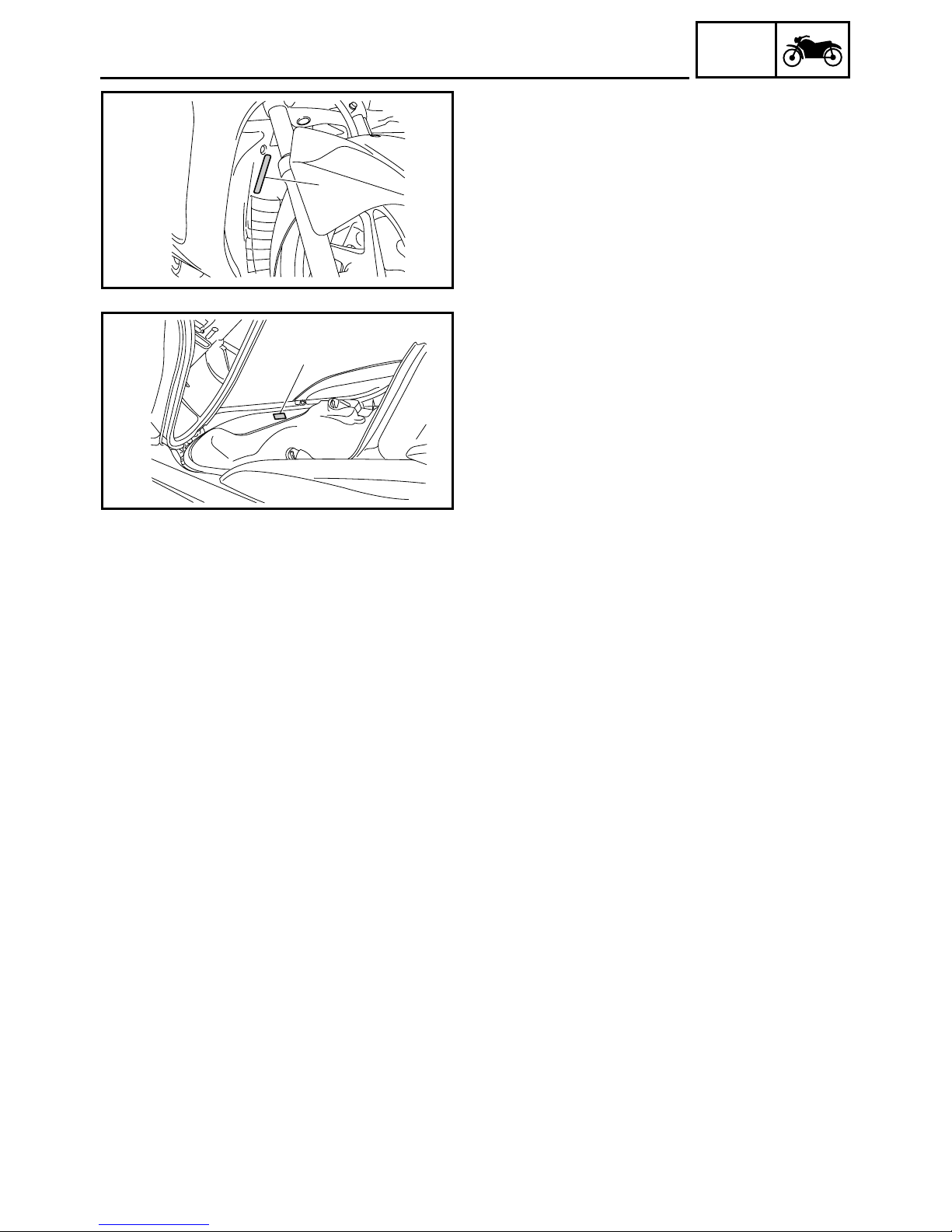
EAS00017
VEHICLE IDENTIFICATION NUMBER
The vehicle identification number 1 is
stamped into the frame.
EAS00018
MODEL LABEL
The model label 1 is affixed inside the storage
box. Record the information on this label in the
space provided. This information will be
needed when ordering spare parts.
GEN
INFO
1 - 1
GEN
FEATURES
EAS00896
FEATURES
OUTLINE OF THE FI SYSTEM
The main function of a fuel supply system is to provide fuel to the combustion chamber at the optimum air-fuel ratio in accordance with the engine operating conditions and the atmospheric temperature. In the conventional carburetor system, the air-fuel ratio of the mixture that is supplied to the
combustion chamber is created by the volume of the intake air and the fuel that is metered by the jet
used in the respective carburetor.
Despite the same volume of intake air, the fuel volume requirement varies by the engine operating
conditions, such as acceleration, deceleration, or operating under a heavy load. Carburetors that
meter the fuel through the use of jets have been provided with various auxiliary devices, so that an
optimum air-fuel ratio can be achieved to accommodate the constant changes in the operating conditions of the engine.
As the requirements for the engine to deliver more performance and cleaner exhaust gases
increase, it becomes necessary to control the air-fuel ratio in a more precise and finely tuned manner. To accommodate this need, this model has adopted an electronically controlled fuel injection
(FI) system, in place of the conventional carburetor system. This system can achieve an optimum
air-fuel ratio required by the engine at all times by using a microprocessor that regulates the fuel
injection volume according to the engine operating conditions detected by various sensors.
The adoption of the FI system has resulted in a highly precise fuel supply, improved engine
response, better fuel economy, and reduced exhaust emissions.
INFO
1
2
1
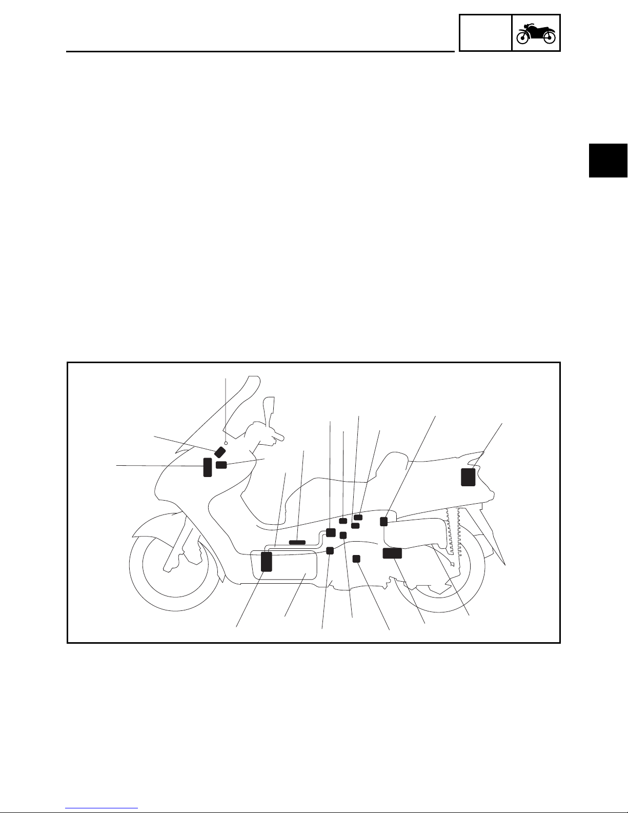
ECU
1
Fuel injection system
2
relay
Engine trouble warn-
3
ing light
Lean angle cut-off
4
switch
3
4
I
Fuel hose
5
Ignition coil
6
Fuel injector
7
Intake air pressure
8
sensor
Throttle position sen-
9
sor
H
5
6
9
7
8
0
F
G
ISC (idle speed con-
0
trol) valve
Intake air temperature
A
sensor
Battery
B
Air filter case
C
Catalytic converter
D
E
D
A
C
Crankshaft position
E
sensor
Coolant temperature
F
sensor
Spark plug
G
Fuel tank
H
Fuel pump
I
B
1 - 2
GEN
FEATURES
EAS00897
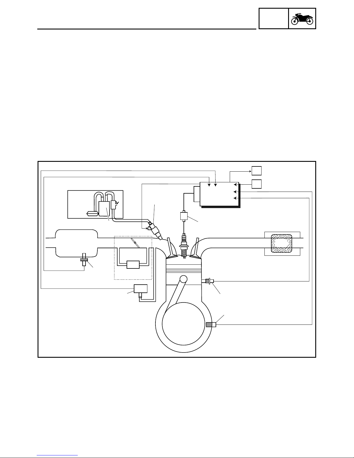
FI SYSTEM
The fuel pump delivers fuel to the fuel injector via the fuel filter. The pressure regulator maintains
the fuel pressure that is applied to the fuel injector at only 250 kPa (2.5 kg/cm
ingly, when the energizing signal from the ECU energizes the fuel injector, the fuel passage opens,
causing the fuel to be injected into the intake manifold only during the time the passage remains
open. Therefore, the longer the length of time the fuel injector is energized (injection duration), the
greater the volume of fuel that is supplied. Conversely, the shorter the length of time the fuel injector
is energized (injection duration), the lesser the volume of fuel that is supplied.
The injection duration and the injection timing are controlled by the ECU. Signals that are input from
the throttle position sensor, crankshaft position sensor, intake air pressure sensor, intake temperature sensor and coolant temperature sensor enable the ECU to determine the injection duration.
The injection timing is determined through the signals from the crankshaft position sensor. As a
result, the volume of fuel that is required by the engine can be supplied at all times in accordance
with the driving conditions.
INFO
2
, 35.6 psi). Accord-
C
È
1
A
É
0
8
Illustration is for reference only.
9
2
Ê
B
4
3
5
6
7
Fuel pump
1
Fuel injector
2
Ignition coil
3
ECU
4
Catalytic converter
5
Coolant temperature
6
sensor
Crankshaft position
7
sensor
Intake air pressure
8
sensor
Throttle body
9
Intake air temperature
0
sensor
A
B
C
1 - 3
Air filter case
Throttle position sensor
ISC (idle speed control) valve
Fuel system
È
Air system
É
Control system
Ê
1
2
3
4
GEN
FEATURES
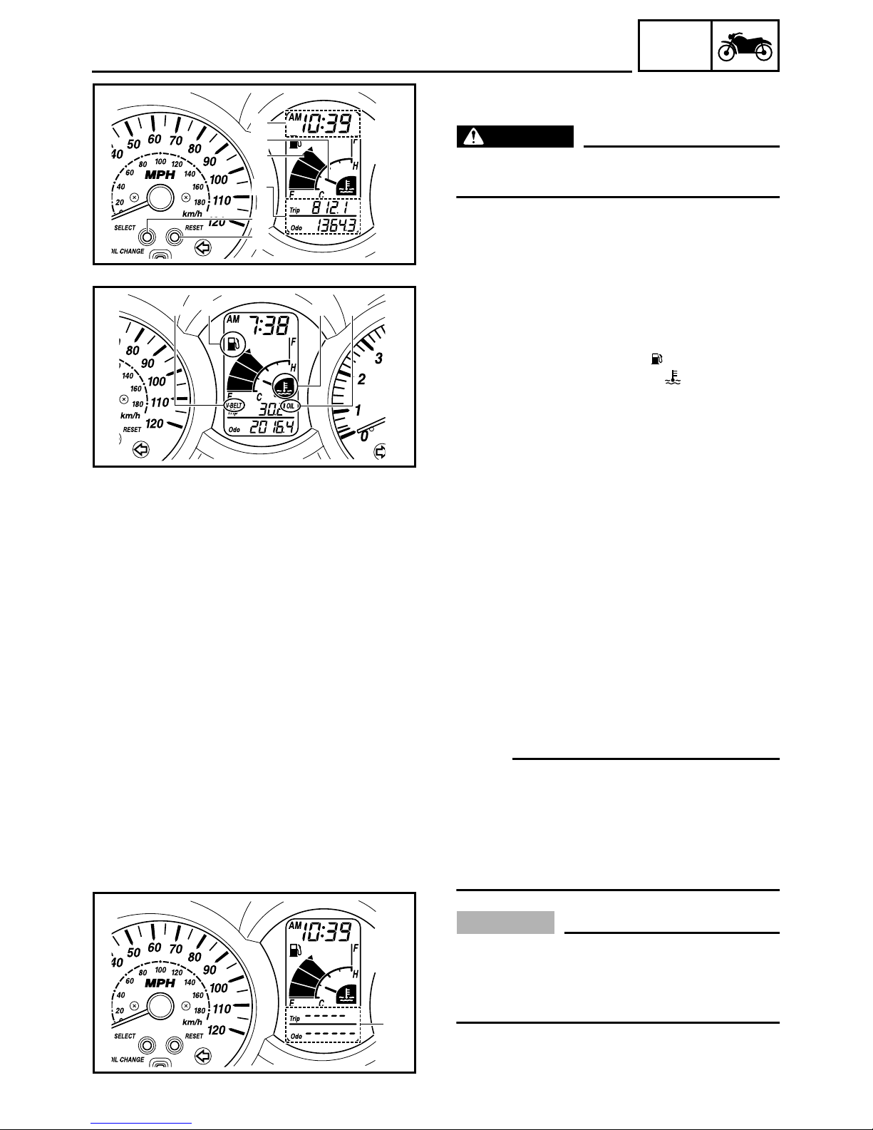
INSTRUMENT FUNCTIONS
Multifunction display
WARNING
Be sure to stop the vehicle before making any
setting changes to the multifunction display.
INFO
5
6
1 Clock/ambient temperature display
2 Coolant temperature meter
3 Fuel meter
4 Odometer/tripmeters
5 “SELECT” button
3412
6 “RESET” button
1 V-belt replacement indicator “V-BELT”
2 Fuel level warning symbol “ ”
3 Coolant temperature symbol “ ”
4 Oil change indicator “OIL”
The multifunction display is equipped with the
following:
• a fuel meter
• a coolant temperature meter
• an odometer (which shows the total distance traveled)
• two tripmeters (which show the distance
traveled since they were last set to zero)
• a fuel reserve tripmeter (which shows the
distance traveled since the bottom segment
of the fuel meter and fuel level warning
symbol started flashing)
• a self-diagnosis device
•a clock
• an ambient temperature display
• an oil change indicator
• a V-belt replacement indicator
NOTE:
• Be sure to turn the key to “ON” before using
the “SELECT” and “RESET” buttons.
• When the key is turned to “ON”, all of the display segments of the multifunction display
will appear one after the other and then disappear, in order to test the electrical circuit.
CAUTION:
If bars 1 appear where the odometer and
tripmeters are normally displayed, the
multi-function display is malfunctioning.
Replace the entire multi-function display.
1
1 - 4
1
GEN
FEATURES
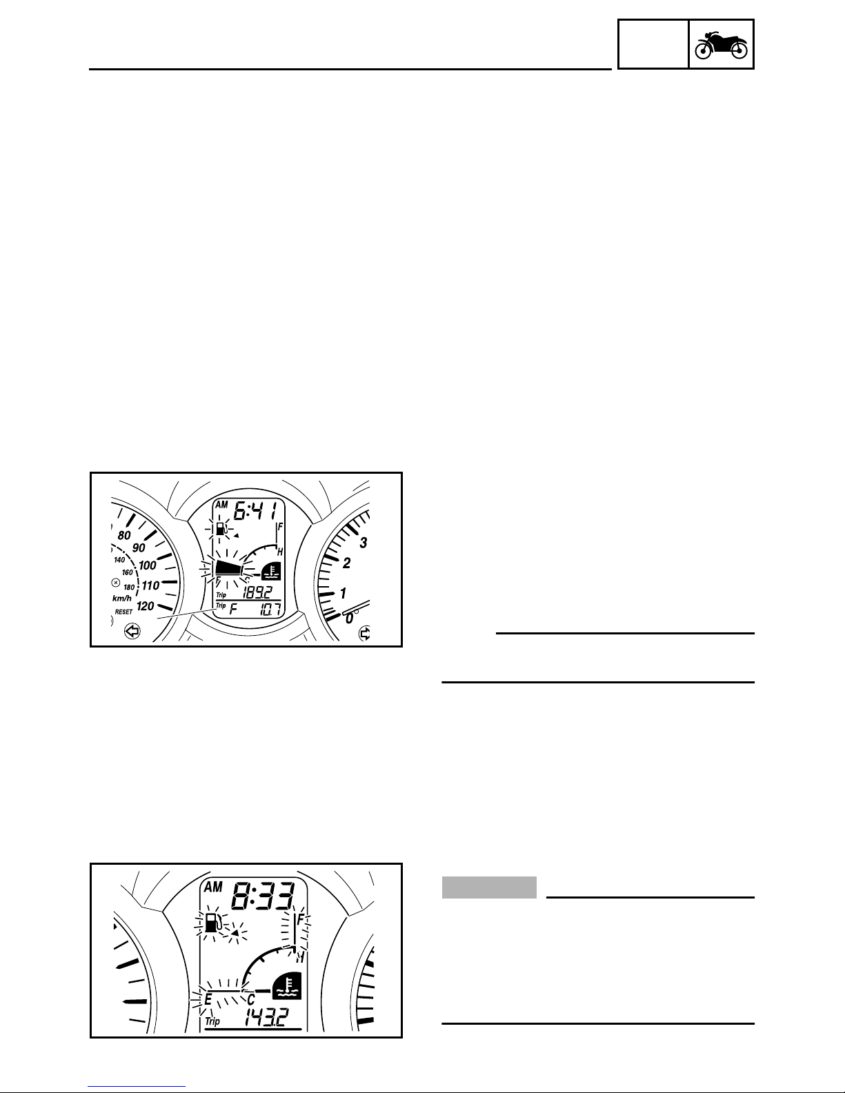
Odometer and tripmeter modes
Pushing the “SELECT” button switches the
display between the odometer mode “ODO”
and the tripmeter modes “TRIP” in the following order:
ODO → TRIP (top) → TRIP (bottom) → ODO
When approximately 2.8 L (0.62 Imp gal,
0.74 US gal) of fuel remains in the fuel tank, the
bottom segment of the fuel meter and fuel level
warning symbol will start flashing, and the display will automatically change to the fuel reserve
tripmeter mode “TRIP F” and start counting the
distance traveled from that point. In that case,
pushing the “SELECT” button switches the display between the various tripmeter and odometer modes in the following order:
TRIP F → TRIP (top) → TRIP (bottom) →
ODO → TRIP F
Fuel reserve tripmeter
1
To reset a tripmeter, select it by pushing the
“SELECT” button, until “TRIP” or “TRIP F”
begins flashing (“TRIP” or “TRIP F” will only
flash for five seconds). While “TRIP” or “TRIP F”
is flashing, push the “RESET” button for at least
one second. If you do not reset the fuel reserve
tripmeter manually, it will reset itself automatically and the display will return to the prior
mode after refueling and traveling 5 km (3 mi).
NOTE:
The display cannot be changed back to “TRIP
F” after pushing the “RESET” button.
INFO
Fuel meter
With the key in the “ON” position, the fuel
meter indicates the amount of fuel in the fuel
tank. The display segments of the fuel meter
disappear towards “E” (Empty) as the fuel level
decreases. When the fuel level reaches the
bottom segment near “E”, the fuel level warning symbol and the bottom segment will flash.
Refuel as soon as possible.
CAUTION:
If the fuel level is not displayed and the fuel
level warning symbol, triangular mark, “E”
line, and “F” line flash in the fuel meter, the
fuel level monitoring system is malfunctioning. Check the fuel sender and the electrical circuit.
1 - 5

GEN
FEATURES
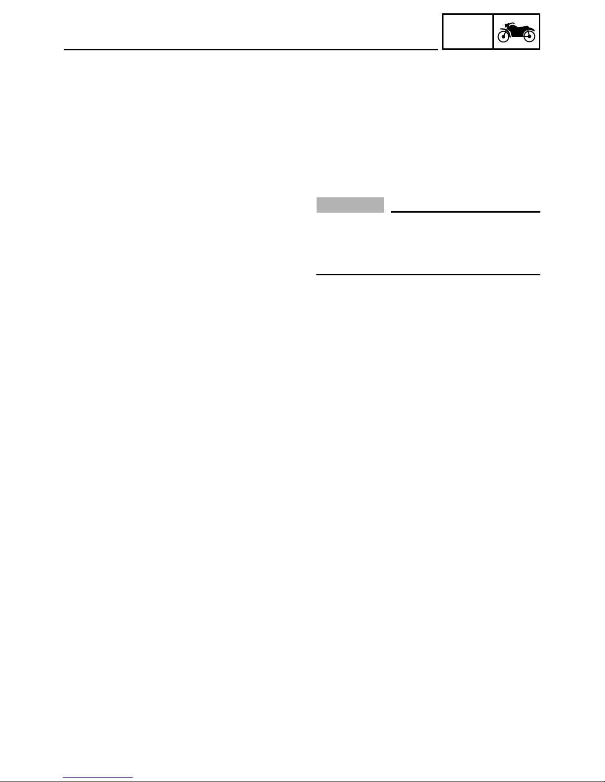
Coolant temperature meter
With the key in the “ON” position, the coolant
temperature meter indicates the temperature
of the coolant. The coolant temperature varies
with changes in the weather and engine load.
If the top segment and coolant temperature
symbol flash, stop the vehicle and let the
engine cool.
CAUTION:
Do not operate the engine if it is overheated.
Oil change indicator “OIL”
This indicator flashes at the initial 1,000 km
(600 mi), then at 5,000 km (3,000 mi) and
every 5,000 km (3,000 mi) thereafter to indicate that the engine oil should be changed.
After changing the engine oil, reset the oil
change indicator. Refer to “To reset the oil
change indicator”. If the engine oil is changed
before the oil change indicator comes on (i.e.
before the periodic oil change interval has
been reached), the indicator must be reset
after the oil change for the next periodic oil
change to be indicated at the correct time.
The electrical circuit of the indicator can be
checked according to the following procedure.
1. Set the engine stop switch to “” and turn
the key to “ON”.
2. Check that the indicator comes on for a few
seconds and then goes off.
3. If the indicator does not come on, check the
electrical circuit. Refer to “SIGNALING
SYSTEM” in chapter 8.
INFO
NOTE:
The oil change indicator may flash when the
engine is revved with the scooter on the centerstand, but this does not indicate a malfunction.
1 - 6
GEN
FEATURES
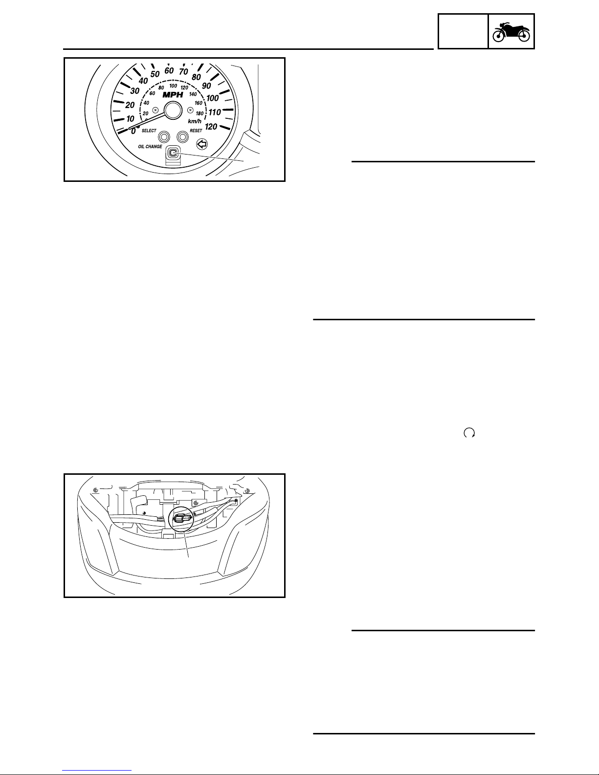
To reset the oil change indicator
1. Turn the key to “ON”.
2. Hold the reset button pushed for two to
eight seconds.
Reset button “OIL CHANGE”
1
3. Release the reset button, and the oil
change indicator will go off.
INFO
1
1
NOTE:
If the engine oil is changed before the oil
change indicator comes on (i.e. before the
periodic oil change interval has been reached),
the indicator must be reset after the oil change
for the next periodic oil change to be indicated
at the correct time. To reset the oil change
indicator before the periodic oil change interval
has been reached, follow the above procedure, but note that the indicator will come on
for 1.4 seconds after releasing the reset button, otherwise repeat the procedure.
V-belt replacement indicator “V-BELT”
This indicator flashes every 20,000 km
(12,500 mi) when the V-belt needs to be
replaced.
The electrical circuit of the indicator can be
checked according to the following procedure.
1. Turn the key to “ON” and make sure that the
engine stop switch is set to “”.
2. If the indicator does not come on, check the
electrical circuit. Refer to “SIGNALING
SYSTEM” in chapter 8.
To reset the V-belt replacement indicator
1. Turn the key to “ON” and make sure that the
engine stop switch is set to “ON”.
2. Disconnect the V-belt replacement reset
coupler 1 for two to ten seconds.
3. And then, connect the V-belt replacement
reset coupler, the V-belt replacement indicator will come on for 1.4 seconds.
And the V-belt replacement indicator will go
off.
NOTE:
If the V-belt is replaced before the V-belt
replacement indicator comes on (i.e. before
the V-belt replacement interval has been
reached), the indicator must be reset after the
V-belt replacement for the next periodic V-belt
replacement to be indicated at the correct
time.
1 - 7
GEN
FEATURES
Self-diagnosis device
This model is equipped with a self-diagnosis
device for various electrical circuits.
If any of those circuits are defective, the multifunction display will indicate a two-digit error
code (e.g., 12, 13, 14).
If the multifunction display indicates an error
code, note the code number, and then check
the vehicle. Refer to “FUEL INJECTION SYSTEM” in chapter 7.
CAUTION:
If the multifunction display indicates an
error code, the vehicle should be checked
as soon as possible in order to avoid
engine damage.
INFO
Clock mode
To set the clock:
1. Push the “SELECT” button and “RESET”
button together for at least two seconds.
2. When the hour digits start flashing, push
the “RESET” button to set the hours.
3. Push the “SELECT” button, and the minute
digits will start flashing.
4. Push the “RESET” button to set the min-
utes.
5. Push the “SELECT” button and then
release it to start the clock. Pushing the
“RESET” button for at least two seconds
switches the clock display to the ambient
temperature display.
1 - 8
GEN
FEATURES
Ambient temperature display
This display shows the ambient temperature
from –10 °C to 50 °C in 1 °C increments. The
temperature displayed may vary from the
ambient temperature. Pushing the “RESET”
button for at least two seconds switches the
ambient temperature display to the clock display.
• When the ambient temperature falls below
–10.0 °C, “–10.0 °C” is displayed.
• When the ambient temperature climbs
above 50.0 °C, “50.0” is displayed.
NOTE:
• If “– – °C” is displayed or “50.0” flashes while
the ambient temperature is between –10.0 °C
and 50.0 °C, there is a problem with the electrical circuit. Check or repair the electric circuit or replace the thermistor.
• The accuracy of the temperature reading
may be affected when riding slowly (approximately under 20 km/h) or when stopped at
traffic signals, railroad crossings, etc.
INFO
1 - 9
IMPORTANT INFORMATION
EAS00020
IMPORTANT INFORMATION
PREPARATION FOR REMOVAL AND
DISASSEMBLY
1. Before removal and disassembly, remove all
dirt, mud, dust and foreign material.
2. Use only the proper tools and cleaning
equipment.
Refer to “SPECIAL TOOLS”.
3. When disassembling, always keep mated
parts together. This includes gears, cylinders, pistons and other parts that have been
“mated” through normal wear. Mated parts
must always be reused or replaced as an
assembly.
4. During disassembly, clean all of the parts
and place them in trays in the order of disassembly. This will speed up assembly and
allow for the correct installation of all parts.
5. Keep all parts away from any source of fire.
GEN
INFO
EAS00021
REPLACEMENT PARTS
Use only genuine Yamaha parts for all
replacements. Use oil and grease recommended by Yamaha for all lubrication jobs.
Other brands may be similar in function and
appearance, but inferior in quality.
EAS00022
GASKETS, OIL SEALS AND O-RINGS
1. When overhauling the engine, replace all
gaskets, seals and O-rings. All gasket surfaces, oil seal lips and O-rings must be
cleaned.
2. During reassembly, properly oil all mating
parts and bearings and lubricate the oil seal
lips with grease.
1 - 10
IMPORTANT INFORMATION
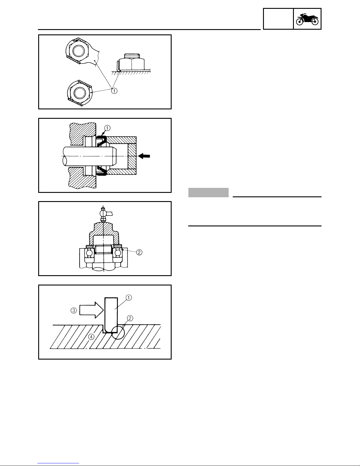
EAS00023
LOCK WASHERS/PLATES AND COTTER
PINS
After removal, replace all lock washers/plates
1
and cotter pins. After the bolt or nut has
been tightened to specification, bend the lock
tabs along a flat of the bolt or nut.
EAS00024
BEARINGS AND OIL SEALS
Install bearings and oil seals so that the manufacturer’s marks or numbers are visible. When
installing oil seals, lubricate the oil seal lips
with a light coat of lithium-soap-based grease.
Oil bearings liberally when installing, if appropriate.
Oil seal
1
GEN
INFO
CAUTION:
_
Do not spin the bearing with compressed
air because this will damage the bearing
surfaces.
Bearing
2
EAS00025
CIRCLIPS
Before reassembly, check all circlips carefully
and replace damaged or distorted circlips.
Always replace piston pin clips after one use.
When installing a circlip 1, make sure the
sharp-edged corner 2 is positioned opposite
the thrust 3 that the circlip receives.
Shaft
4
1 - 11
CHECKING THE CONNECTIONS
EAS00026
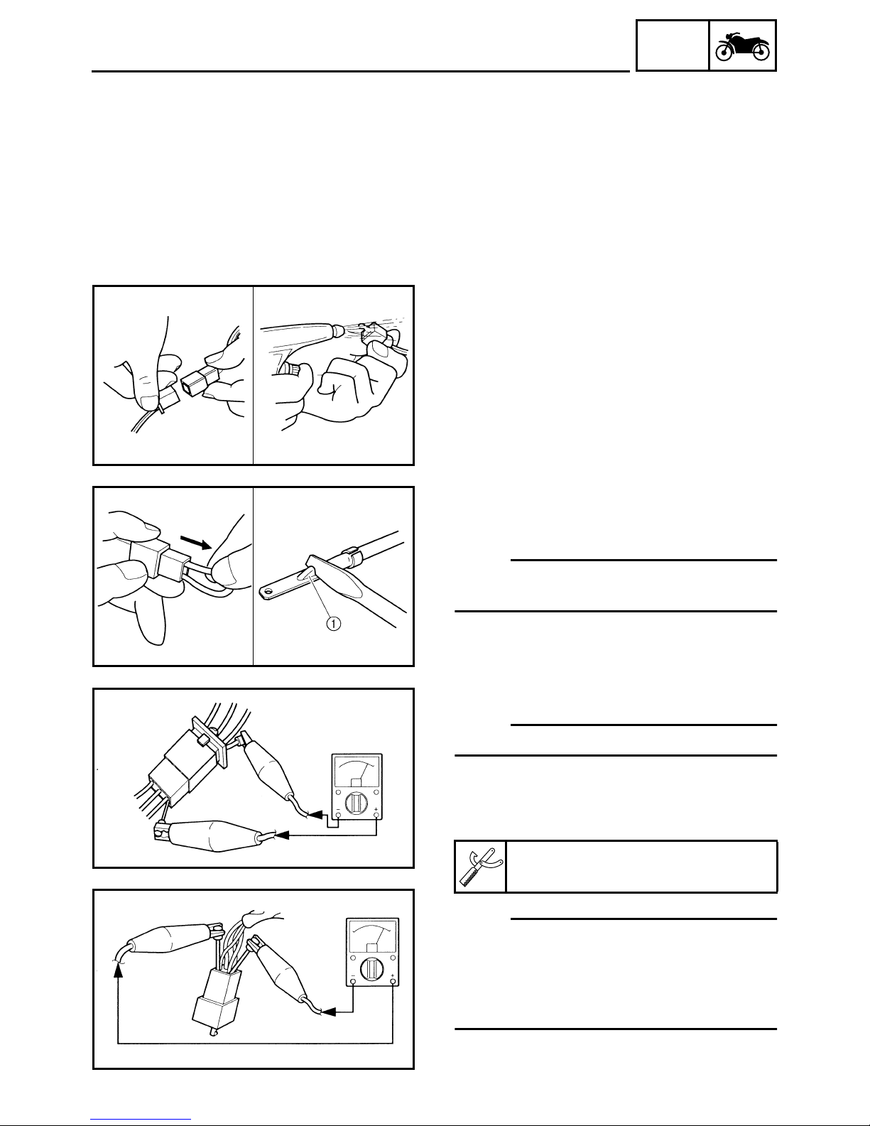
CHECKING THE CONNECTIONS
Check the leads, couplers, and connectors for
stains, rust, moisture, etc.
1. Disconnect:
• lead
• coupler
• connector
2. Check:
• lead
• coupler
• connector
Moisture → Dry with an air blower.
Rust/stains → Connect and disconnect several times.
GEN
INFO
3. Check:
• all connections
Loose connection → Connect properly.
NOTE:
_
If the pin 1 on the terminal is flattened, bend it
up.
4. Connect:
• lead
• coupler
• connector
NOTE:
_
Make sure all connections are tight.
5. Check:
• continuity
(with the pocket tester)
Pocket tester
90890-03112, YU-03112-C
1 - 12
NOTE:
_
• If there is no continuity, clean the terminals.
• When checking the wire harness, perform
steps (1) to (3).
• As a quick remedy, use a contact revitalizer
available at most part stores.
GEN
SPECIAL TOOLS
EAS00027
SPECIAL TOOLS
The following special tools are necessary for complete and accurate tune-up and assembly. Use
only the appropriate special tools as this will help prevent damage caused by the use of inappropriate tools or improvised techniques. Special tools, part numbers or both may differ depending on the
country.
When placing an order, refer to the list provided below to avoid any mistakes.
NOTE:
• For U.S.A. and Canada, use part number starting with “YM-”, “YU-”, or “ACC-”.
• For others, use part number starting with “90890-”.
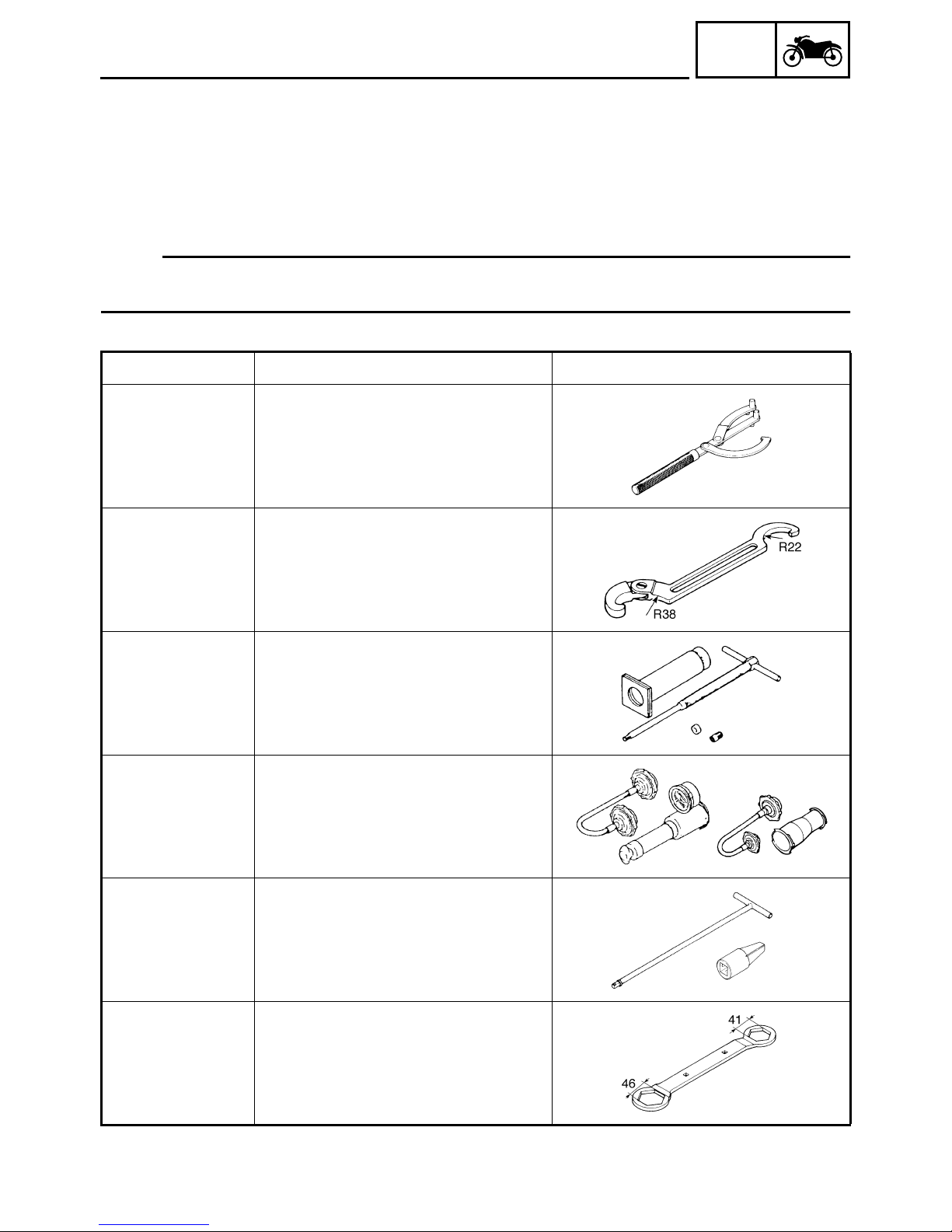
Tool No. Tool name/Function Illustration
Rotor holding tool
90890-01235
YU-01235
This tool is used to hold the primary fixed
sheave and clutch shoe assembly.
INFO
90890-01268
YU-01268
90890-01304
YU-01304
Radiator cap tester
90890-01325
YU-24460-01
Radiator cap tester
adapter
90890-01352
YU-33984
T-handle
90890-01326
Damper rod holder
90890-01460
Ring nut wrench
This tool is used to loosen or tighten the
steering ring nuts.
Piston pin puller set
This tool is used to remove the piston
pins.
Radiator cap tester
Radiator cap tester adapter
These tools are used to check the cooling
system.
T-handle
Damper rod holder
These tools are used to hold the damper
rod when removing or installing the
damper rod.
Locknut wrench
90890-01348
YM-01348
This tool is used to remove or install the
clutch shoe assembly nut.
1 - 13
GEN
SPECIAL TOOLS
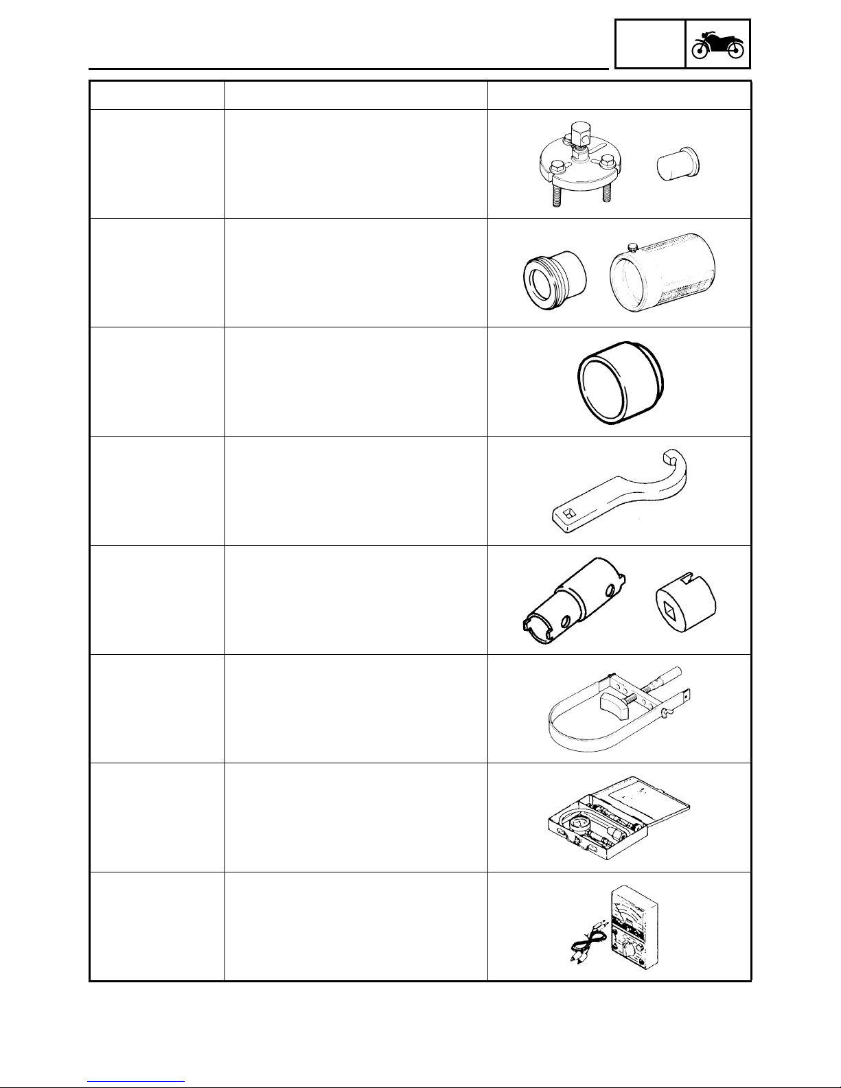
Tool No. Tool name/Function Illustration
INFO
Flywheel puller
90890-01362
Flywheel puller
attachment
90890-04089
YM-33282
Fork seal driver weight
90890-01367
YM-A9409-7
Fork seal driver
attachment
90890-01381
YM-A5142-2
90890-01396
90890-01403
YU-A9472
Flywheel puller
Flywheel puller attachment
This tool is used to remove the generator
rotor.
Fork seal driver weight
Fork seal driver attachment (41 mm)
These tools are used to install the oil
seal, dust seal, and the outer tube bushing of a front fork leg.
Oil seal guide
This tool is used for protecting the oil seal
lip when installing the secondary sliding
sheave.
Steering nut wrench
This tool is used to loosen or tighten the
steering ring nuts.
Pivot shaft wrench
90890-01471
YM-01471
Pivot shaft wrench
adapter
90890-01476
90890-01701
YS-01880-A
Compression gauge
90890-03081
YU-33223
Adapter (compres-
sion gauge)
90890-04082
90890-03112
YU-03112-C
Pivot shaft wrench
Pivot shaft wrench adapter
These tools are used to tighten the subframe adjusting bolt.
Sheave holder
This tool is used to hold the generator
rotor and clutch housing.
Compression gauge
Adapter (compression gauge)
These tools are used to measure engine
compression.
Pocket tester
This tool is used to check the electrical
system.
1 - 14
 Loading...