

Yamaha YP250 User Manual

OWNER’S MANUAL
YP250
5GM-28199-E1

EAU03338
INTRODUCTION
Welcome to the Yamaha world of motorcycling!
As the owner of a YP250, you are benefiting from Yamaha’s vast experience and newest technology
regarding the design and manufacture of high-quality products, which have earned Yamaha a reputation for dependability.
Please take the time to read this manual thoroughly, so as to enjoy all advantages of your YP250.
The owner’s manual does not only instruct you in how to operate, inspect and maintain your scooter,
but also in how to safeguard yourself and others from trouble and injury.
In addition, the many tips given in this manual will help keep your scooter in the best possible condition. If you have any further questions, do not hesitate to contact your Yamaha dealer.
The Yamaha team wishes you many safe and pleasant rides. So, remember to put safety first!
1
2
4
5
6
7
8
9
IMPORTANT MANUAL INFORMATION
Particularly important information is distinguished in this manual by the following notations:
EAU00005
1
Q
2
3
4
5
6
7
8
9
w
cC
NOTE:
NOTE:
8 This manual should be considered a permanent part of this scooter and should remain with it
8 Yamaha continually seeks advancements in product design and quality. Therefore, while this
The Safety Alert Symbol means ATTENTION! BECOME ALERT! YOUR SAFETY IS
INVOLVED!
Failure to follow WARNING instructions could result in severe injury or death to
the scooter operator, a bystander, or a person inspecting or repairing the scooter.
A CAUTION indicates special precautions that must be taken to avoid damage to
the scooter.
A NOTE provides key information to make procedures easier or clearer.
even if the scooter is subsequently sold.
manual contains the most current product information available at the time of printing, there
may be minor discrepancies between your scooter and this manual. If you have any questions concerning this manual, please consult your Yamaha dealer.

IMPORTANT MANUAL INFORMATION
EW000002
w
PLEASE READ THIS MANUAL CAREFULLY AND COMPLETELY BEFORE OPERATING
THIS SCOOTER.
1
2
4
5
6
7
8
9

1
2
3
4
5
EAU03337
6
YP250
OWNER’S MANUAL
7
© 2000 by Yamaha Motor Co., Ltd.
1st Edition, August 2000
8
All rights reserved.
Any reprinting or unauthorized use
9
without the written permission of
Yamaha Motor Co., Ltd.
is expressly prohibited.
Printed in Japan.

EAU00009
TABLE OF CONTENTS
1 GIVE SAFETY THE RIGHT OF WAY
2 DESCRIPTION
3 INSTRUMENT AND CONTROL FUNCTIONS
4 PRE-OPERATION CHECKS
5 OPERATION AND IMPORTANT RIDING POINTS
6 PERIODIC MAINTENANCE AND MINOR REPAIR
7 SCOOTER CARE AND STORAGE
8 SPECIFICATIONS
9 CONSUMER INFORMATION
INDEX
1
2
3
4
5
6
7
8
9


GIVE SAFETY THE RIGHT OF WAY
GIVE SAFETY THE RIGHT OF WAY ................................................1-1
Further safe-riding points....................................................................1-2
1

Q GIVE SAFETY THE RIGHT OF WAY
Scooter are fascinating vehicles, which can give you an unsurpassed feeling of power and freedom.
However, they also impose certain limits, which you must accept; even the best scooter does not
1
2
3
4
ignore the laws of physics.
Regular care and maintenance are essential for preserving value and operating condition of your
scooter. Moreover, what is true for the scooter is also true for the rider: good performance depends on
being in good shape. Riding under the influence of medication, drugs and alcohol is, of course, out of
the question. Scooter riders—more than car drivers—must always be at their mental and physical
best. Under the influence of even small amounts of alcohol, there is a tendency to take dangerous
risks.
EAU00021
5
Protective clothing is as essential for the scooter rider as seat belts are for car drivers and passengers. Always wear a complete motorcycle suit (whether made of leather or tear-resistant synthetic
6
materials with protectors), sturdy boots, motorcycle gloves and a properly fitting helmet. Optimum protective wear, however, should not encourage carelessness. Although full-coverage helmets and suits,
in particular, create an illusion of total safety and protection, motorcyclists will always be vulnerable.
7
Riders who lack critical self-control run the risk of going too fast and are apt to take chances. This is
even more dangerous in wet weather. The good motorcyclist rides safely, predictably and defensive-
8
9
ly—avoiding all dangers, including those caused by others.
Enjoy your ride!
1-1

Q GIVE SAFETY THE RIGHT OF WAY
EAU03099
Further safe-riding points
8 Be sure to signal clearly when making turns.
8 Braking can be extremely difficult on a wet road. Avoid hard braking, because the scooter could
slide. Apply the brakes slowly when stopping on a wet surface.
8 Slow down as you approach a corner or turn. Once you have completed a turn, accelerate slowly.
8 Be careful when passing parked cars. A driver might not see you and open a door in your path.
8 Railroad crossings, streetcar rails, iron plates on road construction sites, and manhole covers
become extremely slippery when wet. Slow down and cross them with caution. Keep the scooter
upright, otherwise it could slide out from under you.
8 The brake pads could get wet when you wash the scooter. After washing the scooter, check the
brakes before riding.
8 Always wear a helmet, gloves, trousers (tapered around the cuff and ankle so they do not flap),
and a bright colored jacket.
8 Do not carry too much luggage on the scooter. An overloaded scooter is unstable.
1
2
3
4
5
6
7
8
1-2
9

1
2
3
4
5
6
7
8
9

DESCRIPTION
Left view .............................................................................................2-1
Right view...........................................................................................2-2
Controls and instruments....................................................................2-3
2
DESCRIPTION
1 2
3
4
56
7
8
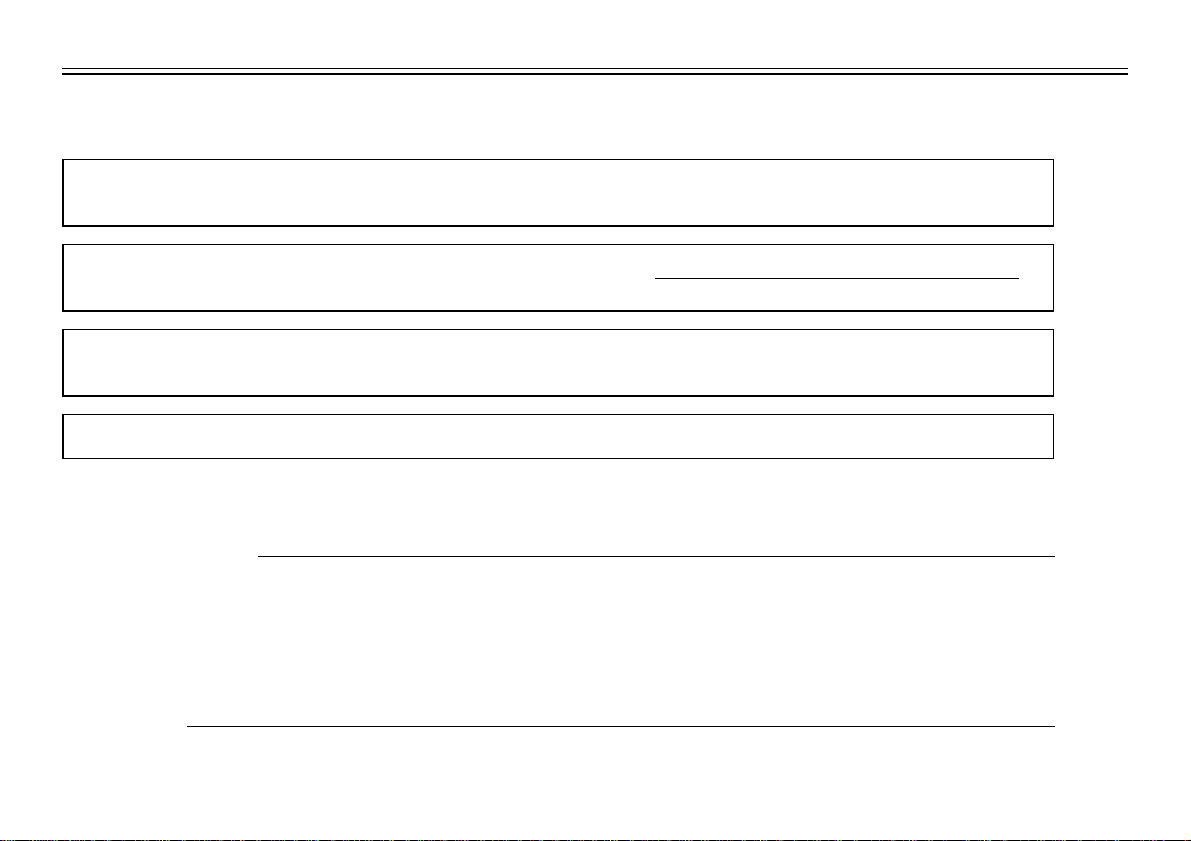
Left view
1
2
3
EAU00026
4
5
6
7
8
9
1. Rear storage compartment (page 3-13)
2. Grab bar (Page 5-2)
3. Shock absorber spring preload
adjusting ring (page 3-14)
4. Air filter element (page 6-20)
5. V-belt case air filter element (page 6-21)
6. Centerstand (page 6-29)
7. Sidestand (page 3-15, 6-29)
8. Fuel tank cap (page 3-9)
2-1
10
11
12
13
16
17
18
15, 14
9
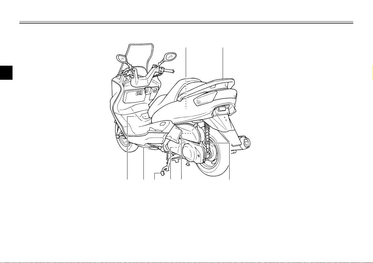
Right view
DESCRIPTION
1
2
3
4
5
9. Passenger seat
10. Rider seat (page 3-11)
11. Air flow louver (page 6-22)
12. Headlight (page 6-34)
13. Radiator
14. Battery (page 6-31)
15. Fuse box (page 6-33)
16. Coolant reservoir cap (page 6-19)
17. Coolant level check window (page 6-19)
18. Engine oil filler cap (page 6-15)
2-2
6
7
8
9
1
2 3
4 5
6
7 8 9
10
11
12
DESCRIPTION
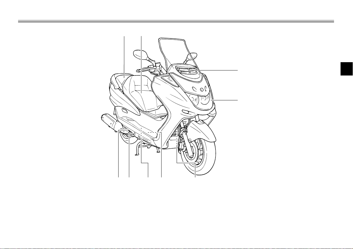
Controls and instruments
1
2
3
4
5
6
7
8
1. Rear brake lever (page 3-8)
9
2. Left handlebar switches (page 3-5)
3. Front storage compartment A (page 3-12)
4. Clock (page 3-5)
5. Speedometer unit (page 3-3)
6. Coolant temperature gauge (page 3-4)
7. Fuel gauge (page 3-4)
8. Right handlebar switches (page 3-6)
9. Front brake lever (page 3-8)
10. Throttle grip
11. Front storage compartment B (page 3-13)
12. Main switch/steering lock (page 3-1)
2-3

INSTRUMENT AND CONTROL FUNCTIONS
Main switch/steering lock....................................................................3-1
Indicator lights ....................................................................................3-2
Speedometer unit...............................................................................3-3
Self-diagnosis device .........................................................................3-3
Anti-theft alarm (optional)...................................................................3-4
Fuel gauge..........................................................................................3-4
Coolant temperature gauge................................................................3-4
Clock...................................................................................................3-5
Handlebar switches............................................................................3-5
Front brake lever ................................................................................3-8
Rear brake lever.................................................................................3-8
Fuel tank cap......................................................................................3-9
Fuel...................................................................................................3-10
Catalytic converter............................................................................3-10
Rider seat.........................................................................................3-11
Adjusting the rider seat.....................................................................3-12
Storage compartments.....................................................................3-12
Adjusting the shock absorber assemblies........................................3-14
Sidestand..........................................................................................3-15
Ignition circuit cut-off system............................................................3-15
3
I
G
N
I
T
I
O
N
P
LOCK
ON
OFF
OPEN
PUSH
PUSH
INSTRUMENT AND CONTROL FUNCTIONS
EAU00027
1
2
3
4
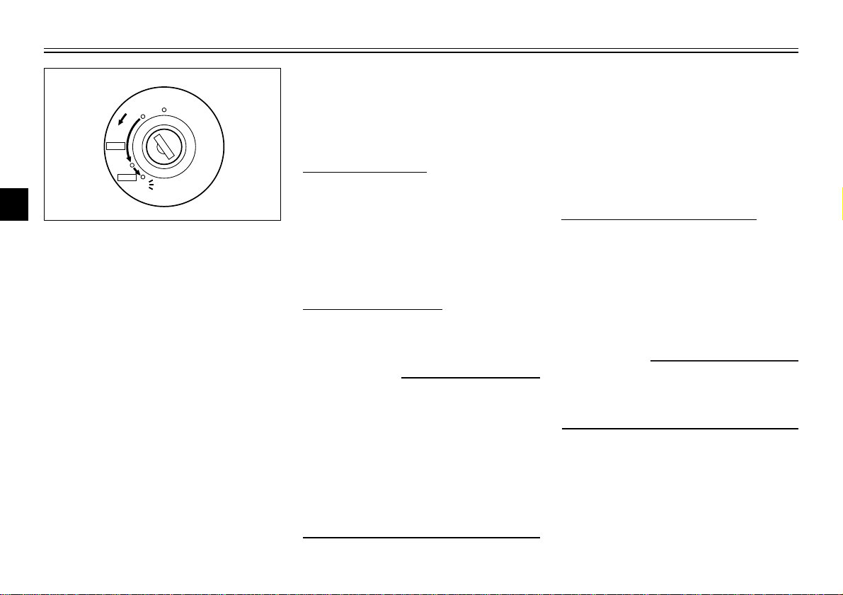
Main switch/steering lock
The main switch/steering lock con-
5
trols the ignition and lighting systems,
and is used to lock the steering. The
6
various positions are described
below.
7
ON
All electrical systems are supplied
8
with power, and the engine can be
started. The key cannot be removed.
9
OFF
All electrical systems are off. The key
can be removed.
EAU00029
EAU00036
EAU00038
EAU00040
LOCK
The steering is locked, and all electrical systems are off. The key can be
removed.
To lock the steering
1. Turn the handlebars all the way
to the left.
2. Push the key in from the “OFF”
position, and then turn it to
“LOCK” while still pushing it.
3. Remove the key.
To unlock the steering
Push the key in, and then turn it to
“OFF” while still pushing it.
EW000016
w
Never turn the key to “OFF” or
“LOCK” while the scooter is moving, otherwise the electrical systems will be switched off, which
may result in loss of control or an
accident. Make sure that the scooter is stopped before turning the
key to “OFF” or “LOCK”.
3-1
EAU03733
.
(Parking)
The steering is locked, and the taillight, license light and auxiliary light
are on, but all other electrical systems are off. The key can be
removed.
To turn the main switch to
“.”
:
1. Turn the key to “LOCK”.
2. Slightly turn the key counterclockwise until it stops.
3. While still turning the key counterclockwise, push it in until it
snaps into place.
ECA00043
cC
Do not use the parking position for
an extended length of time, otherwise the battery may discharge.

1
3 4
2
INSTRUMENT AND CONTROL FUNCTIONS
1. Oil change indicator light “7”
2. High beam indicator light “&”
3. Left turn signal indicator light “4”
4. Right turn signal indicator light “6”
EAU00056
Indicator lights
EAU03734
Oil change indicator light “7”
This indicator light comes on at the
initial 1,000 km and every 3,000 km
thereafter to indicate that the engine
oil should be changed.
After changing the engine oil, reset
the oil change indicator light.(See
page 6-17 for the resetting procedure.)
The electrical circuit of the indicator
light can be checked according to the
following procedure.
1. Set the engine stop switch to “#”
and turn the key to “ON”.
2. Check that the indicator comes
on for a few seconds and then
goes off.
If the indicator light does not
come on, have a Yamaha dealer
check the electrical circuit.
NOTE:
The oil change indicator light may
flash when the engine is revved with
the scooter on the centerstand, but
this does not indicate a malfunction.
EAU00063
High beam indicator light “&”
This indicator light comes on when
the high beam of the headlight is
switched on.
EAU03299
Turn signal indicator lights
“4”/“6”
The corresponding indicator light
flashes when the turn signal switch is
pushed to the left or right.
1
2
3
4
5
6
7
8
9
3-2
INSTRUMENT AND CONTROL FUNCTIONS
1 2 3
1
2
3
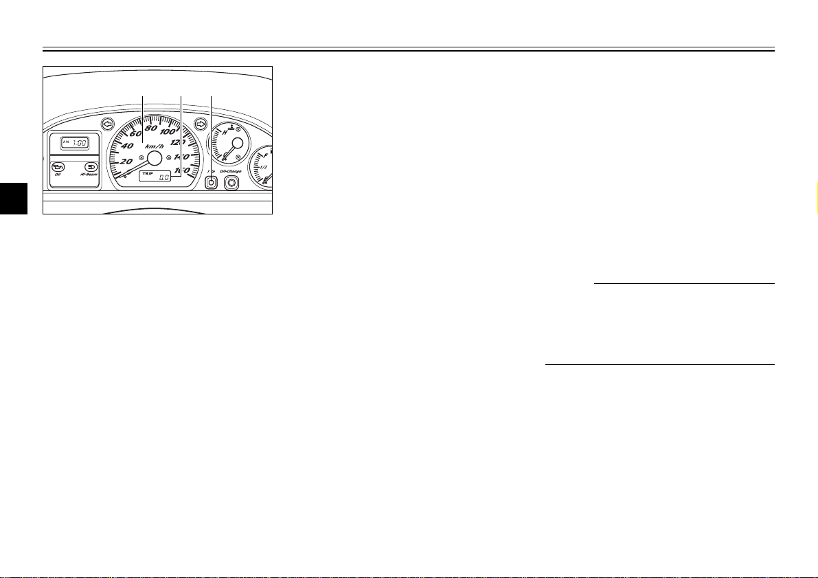
1. Speedometer
4
2. Odometer/tripmeter
3. “TRIP” button
5
Speedometer unit
The speedometer unit is equipped
6
with a speedometer, an odometer
and a tripmeter. The speedometer
7
shows riding speed. The odometer
shows the total distance traveled.
The tripmeter shows the distance
8
traveled since it was last set to zero.
9
Pushing the “TRIP” button switches
the display between the odometer
mode “ODO” and the tripmeter mode
“TRIP”. To reset the tripmeter, enter
the “TRIP” mode, and then hold down
EAU01586
the “TRIP” button for at least one
second. The tripmeter can be used
together with the fuel gauge to estimate the distance that can be traveled with a full tank of fuel. This information will enable you to plan future
fuel stops.
EAU03740
Self-diagnosis device
This model is equipped with a selfdiagnosis device for the throttle position sensor, oil change indicator light,
speedometer unit circuits. If any of
those circuits are defective, the oil
change indicator light will flash.
If the indicator light flashes or comes
on, have a Yamaha dealer check the
motorcycle as soon as possible.
NOTE:
The oil change indicator light may
flash when the engine is revved with
the scooter on the centerstand, but
this does not indicate a malfunction.
3-3
1
1
2
EAU00109
Anti-theft alarm (optional)
This scooter can be equipped with an
optional anti-theft alarm by a Yamaha
dealer. Contact a Yamaha dealer for
more information.
INSTRUMENT AND CONTROL FUNCTIONS
1
2
3
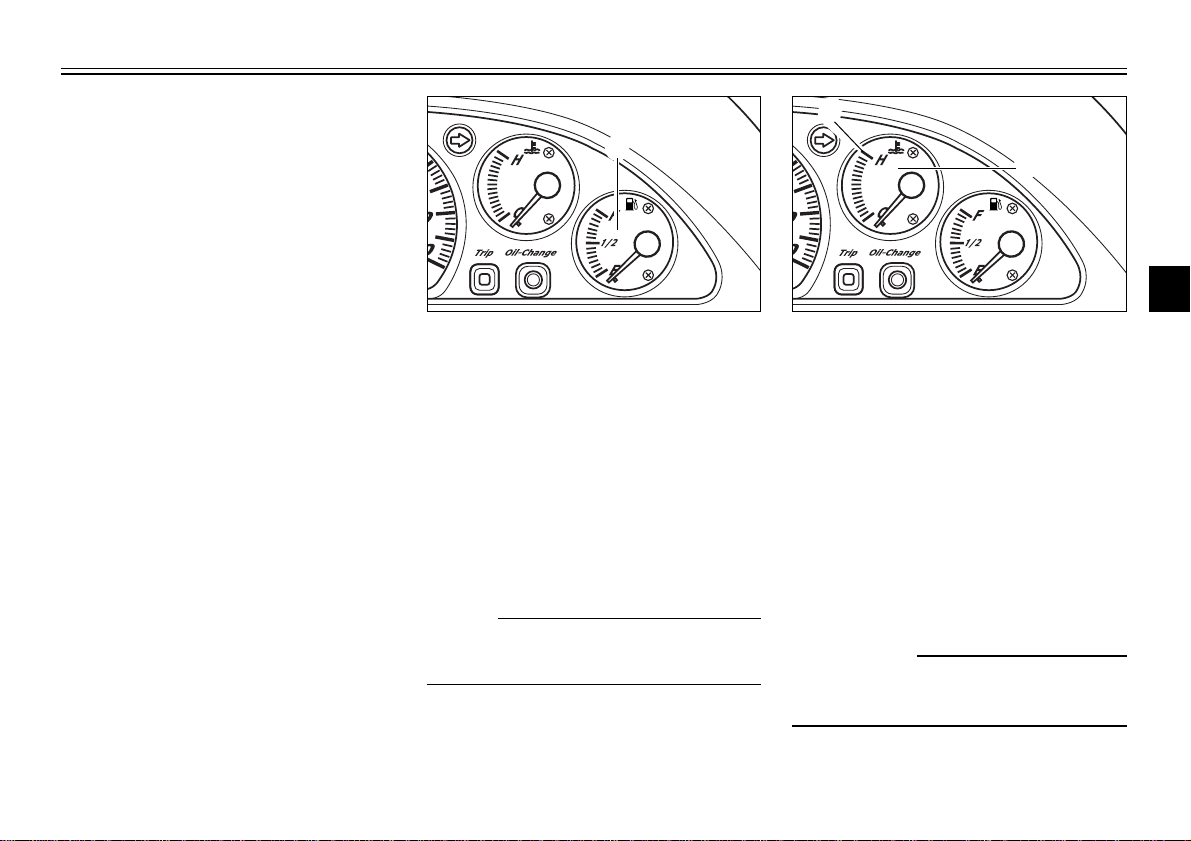
1. Fuel gauge
EAU00110
Fuel gauge
The fuel gauge indicates the amount
of fuel in the fuel tank. The needle
moves towards “E” (Empty) as the
fuel level decreases. When the needle reaches “E”, approximately 1.0 L
of fuel remain in the fuel tank. If this
occurs, refuel as soon as possible.
NOTE:
Do not allow the fuel tank to empty
itself completely.
3-4
1. Coolant temperature gauge
2. Red mark
EAU03124
Coolant temperature gauge
This gauge indicates the coolant temperature when the main switch is on.
The engine operating temperature
will vary with changes in weather and
engine load. If the needle points to
the red mark, stop your scooter and
let the engine cool. (See page
6-18 for details.)
EC000002
cC
Do not operate the engine if it is
overheated.
4
5
6
7
8
9
INSTRUMENT AND CONTROL FUNCTIONS
2
3 1
1
2
3
4
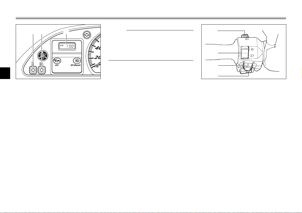
NOTE:
To set the clock after the power
1
2
3
source has been cut, first set the time
to 1:00 AM, and then set the clock to
the correct time.
1. Digital clock
4
2. Hour setting button “h”
3. Minute setting button “m”
5
Clock
The digital clock shows the time
6
regardless of the main switch position.
7
To set the clock:
1. Turn the key to “ON”.
8
2. Push or hold the hour setting
9
button “h” to change the hours.
3. Push or hold the minute setting
button “m” to change the minutes.
EAU03800
3-5
1. Pass switch “&”
2. Dimmer switch
3. Turn signal switch
4. Horn switch “*”
EAU00118
Handlebar switches
EAU00119
Pass switch “&
Press this switch to flash the headlight.
Dimmer switch
Set this switch to “&” for the high
beam and to “%” for the low beam.
”
EAU00121
1
2
3
EAU00127
Turn signal switch
To signal a right-hand turn, push this
switch to “6”. To signal a left-hand
turn, push this switch to “4”. When
released, the switch returns to the
center position. To cancel the turn
signal lights, push the switch in after
it has returned to the center position.
EAU00129
Horn switch “*”
Press this switch to sound the horn.
INSTRUMENT AND CONTROL FUNCTIONS
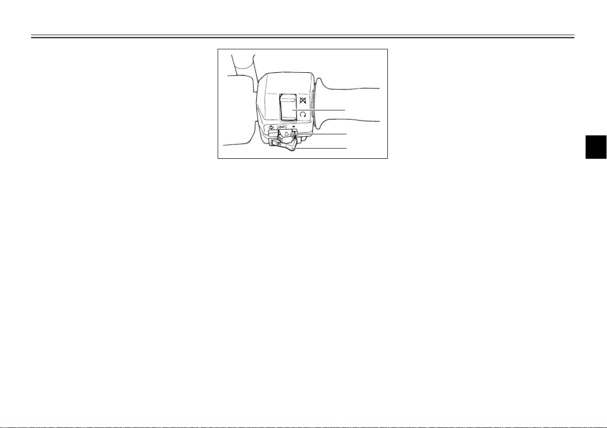
1. Engine stop switch
2. Light switch
3. Start switch “,”
EAU01871
Light switch
Set this switch to “'” to turn on
the auxiliary light, meter lighting, taillight and license plate light. Set the
switch to “:” to turn on the headlight
also.
1
2
3
4
5
6
7
8
9
3-6
INSTRUMENT AND CONTROL FUNCTIONS
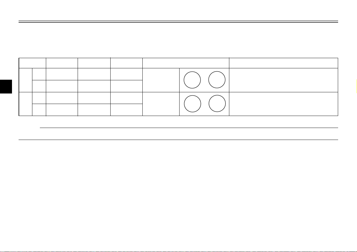
EAU00136
Headlight variations
1
Left Right Aux
2
%
2
1
1
3
&
1
3
'
'
Halogen
bulb
Bulb to be used
3 : High beam light on 2 : Low beam light on
' : Auxiliary light on 1 : Light off
Destination
12V
55W
12V
60/55W
Germany, Belgium, Switzerland, Spain
France, Greece, Italy, Netherlands,
Norway, Portugal, Sweden
%
4
2
&
1
3
2
1
'
'
Halogen
bulb
5
NOTE:
Right and left are defined as seen when standing in front of the scooter.
6
7
8
9
3-7
12V
60/55W
12V
55W
England

INSTRUMENT AND CONTROL FUNCTIONS
1
2
3
1
1
1
2
3
1. Engine stop switch
2. Light switch
3. Start switch “,”
EAU00138
Engine stop switch
Set this switch to “$” to stop the
engine in case of an emergency,
such as when the scooter overturns
or when the throttle cable is stuck.
EAU00143
Start switch “,”
Push this switch to crank the engine
with the starter.
EC000005
cC
See page 5-1 for starting instructions prior to starting the engine.
1. Front brake lever
EAU03378
Front brake lever
The front brake lever is located at the
right handlebar grip. To apply the
front brake, pull this lever toward the
handlebar grip.
3-8
1. Rear brake lever
EAU00163
Rear brake lever
The rear brake lever is located on the
left handlebar grip. To apply the rear
brake, pull this lever toward the handlebar grip.
4
5
6
7
8
9
INSTRUMENT AND CONTROL FUNCTIONS
1
2
1
1
1
2
3
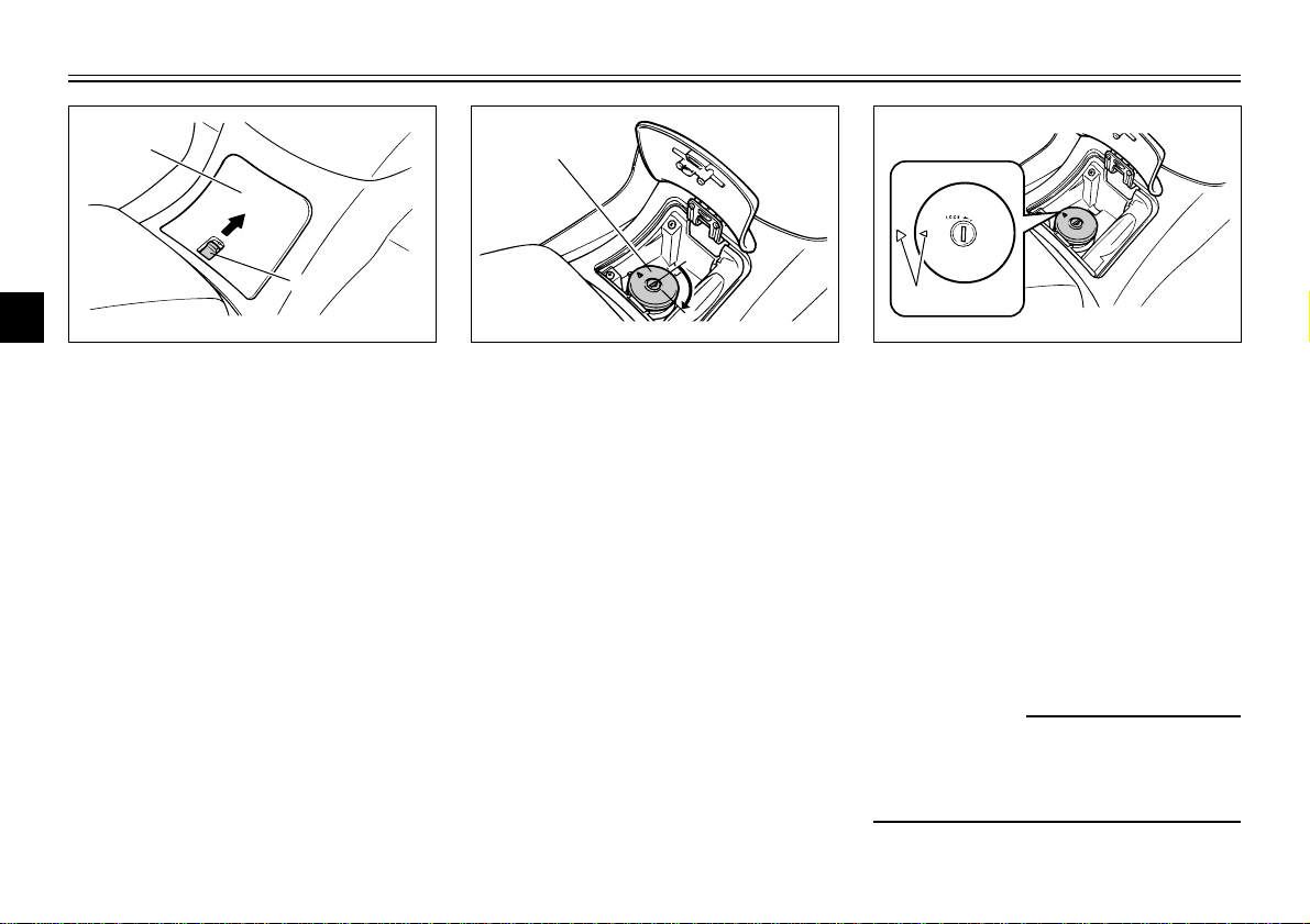
1. Lid
4
2. Lever
Fuel tank cap
5
To open the fuel tank cap
6
1. Open the lid by sliding the lever
forward, and then pull the lever
7
up.
8
9
EAU03090
1. Fuel tank cap
2. Insert the key into the lock and
turn it clockwise. The lock will be
released and the fuel tank cap
can be removed.
3-9
1. Match marks
To install the fuel tank cap
1. Align the match marks, insert the
fuel tank cap into the tank opening, and then push down on the
cap.
2. Turn the key counterclockwise to
the original position, and then
remove it.
3. Close the lid.
EWA00028
w
Be sure the cap is properly
installed and locked in place
before riding the scooter.
INSTRUMENT AND CONTROL FUNCTIONS
1
2
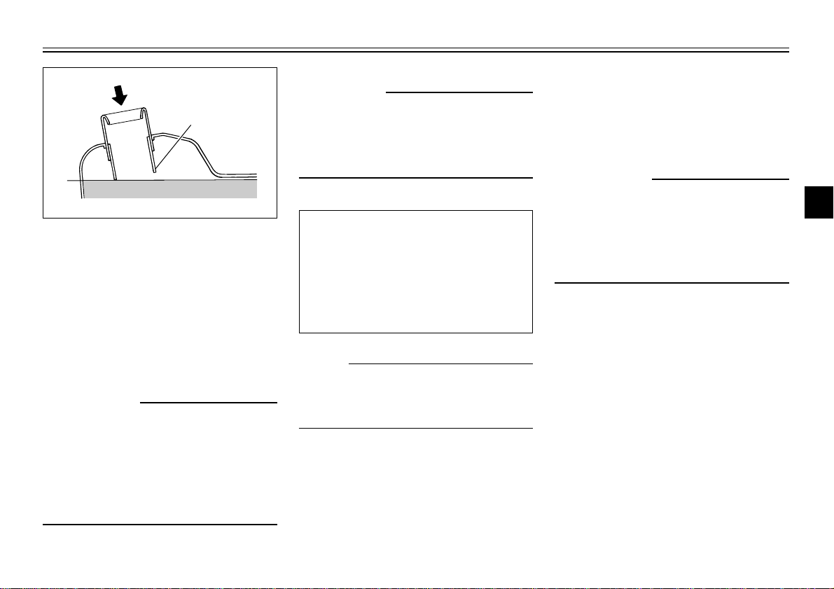
1. Filler tube
2. Fuel level
EAU01183
Fuel
Make sure that there is sufficient fuel
in the tank. Fill the fuel tank to the
bottom of the filler tube as shown in
the illustration.
EW000130
w
8 Do not overfill the fuel tank,
otherwise it may overflow
when the fuel warms up and
expands.
8 Avoid spilling fuel on the hot
engine.
EAU00185
cC
Immediately wipe off spilled fuel
with a clean, dry, soft cloth, since
fuel may deteriorate painted surfaces or plastic parts.
EAU03626
Recommended fuel:
Regular unleaded gasoline with
a research octane number of 91
or higher
Fuel tank capacity (Total amount):
12 L
NOTE:
If knocking (or pinging) occurs, use
gasoline of a different brand or with a
higher octane grade.
EAU03098
Catalytic converter
This scooter is equipped with a catalytic converter in the muffler.
EW000128
w
The exhaust system is hot after
operation. Make sure that the
exhaust system has cooled down
before doing any maintenance
work.
1
2
3
4
5
6
7
8
9
3-10
INSTRUMENT AND CONTROL FUNCTIONS
I
G
N
I
T
I
O
N
P
LOCK
ON
OFF
OPEN
PUSH
PUSH
a
1
EC000114
cC
The following precautions must be
1
observed to prevent a fire hazard
or other damages.
2
8 Use only unleaded gasoline.
The use of leaded gasoline will
3
4
5
6
7
8
cause unrepairable damage to
the catalytic converter.
8 Never park the scooter near
possible fire hazards such as
grass or other materials that
easily burn.
8 Do not allow the engine to idle
too long.
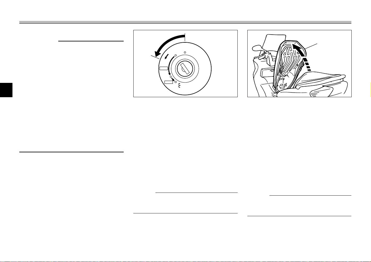
a. Open.
Rider seat
To open the rider seat
1. Place the scooter on the centerstand.
2. Insert the key into the main
switch, and then turn it counterclockwise.
EAU03091
1. Rider seat
3. Fold the rider seat up.
To close the rider seat
1. Fold the rider seat down, and
then push it down to lock it in
place.
2. Remove the key from the main
switch if the scooter will be left
unattended.
9
Do not push inward when turning the
key.
3-11
NOTE:
NOTE:
Make sure that the seat is properly
secured before riding.
INSTRUMENT AND CONTROL FUNCTIONS
1 1
2 2
1
2
a
1
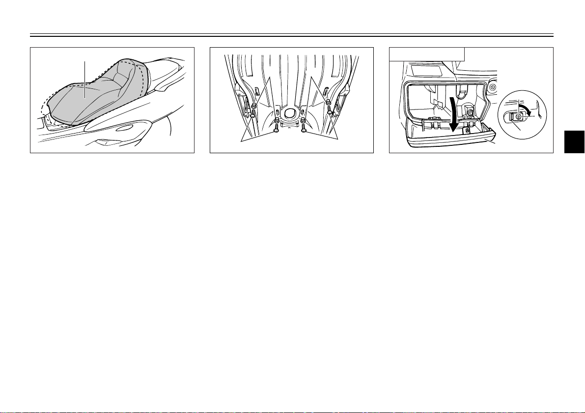
1. Rider seat
EAU03096
Adjusting the rider seat
The rider seat can be adjusted as follows to change the riding position.
1. Open the rider seat.
1. Bolt (×4)
2. Collar (×4)
2. Remove the bolts and collars.
3. Slide the rider seat forward or
backward to the desired position.
4. Install the collars and securely
tighten the bolts.
5. Close the rider seat.
3-12
Compartment A
1. Button
2. Lid
a. Lock.
EAU03331
Storage compartments
Front storage compartment A
To open the storage compartment
when it is locked, insert the key in the
lock, turn it counterclockwise, and
then grasp the lock while pushing the
button in.
To open the storage compartment
when it is unlocked, simply grasp the
lock while pushing the button in.
To lock the storage compartment,
push the lid into the original position,
insert the key in the lock, turn it clockwise, and then remove it.
1
2
3
4
5
6
7
8
9
INSTRUMENT AND CONTROL FUNCTIONS
1
2
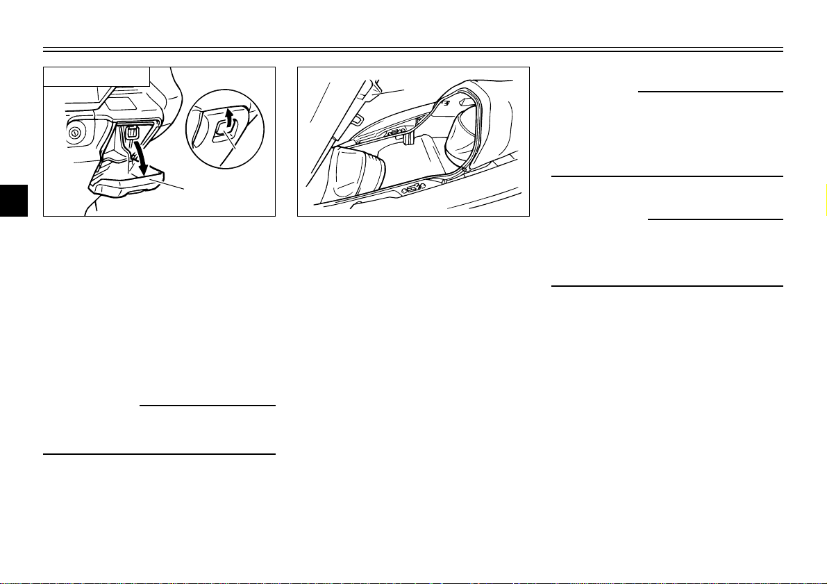
Compartment B
1
2
3
1. Lever
4
2. Lid
Front storage compartment B
To open the storage compartment,
5
slide the lever up, and then pull on
the lever.
6
To close the storage compartment,
push the lid into the original position.
7
8
w
Do not store heavy items in this
9
compartment.
EWA00034
1
1. Rider seat
Rear storage compartment
Two helmets can be stored in the
storage compartment under the
seats. (See page 3-11 for rider seat
opening and closing procedures.)
ECA00051
cC
Do not leave the rider seat open
for an extended period of time as
the storage compartment light may
cause the battery to discharge.
EWA00035
w
Do not exceed the loading limits:
Front storage compartment A: 2 kg
Rear storage compartment: 5 kg
3-13
INSTRUMENT AND CONTROL FUNCTIONS
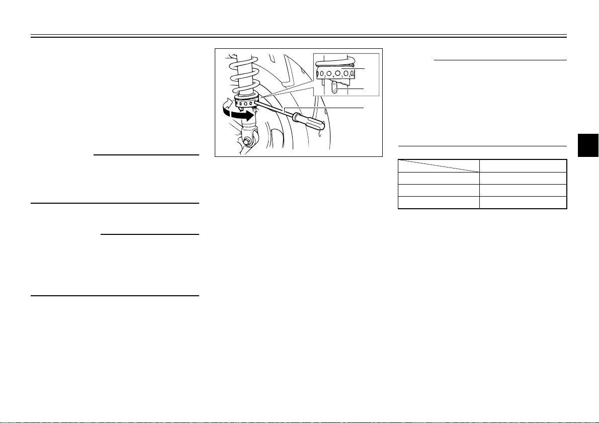
Setting
Minimum (soft) 1
Standard 4
Maximum (hard) 7
a
b
1
2
3
EAU03625
Adjusting the shock
absorber assemblies
Each shock absorber assembly is
equipped with a spring preload
adjusting ring.
EC000015
cC
Never attempt to turn an adjusting
mechanism beyond the maximum
or minimum settings.
EW000040
w
Always adjust both shock
absorber assemblies equally, otherwise poor handling and loss of
stability may result.
1. Spring preload adjusting ring
2. Position indicator
3. Spring preload adjusting tool
Adjust the spring preload as follows.
To increase the spring preload and
thereby harden the suspension, turn
the adjusting ring on each shock
absorber assembly in direction a. To
decrease the spring preload and
thereby soften the suspension, turn
the adjusting ring on each shock
absorber assembly in direction b.
NOTE:
8 Align the appropriate notch in the
adjusting ring with the position
indicator on the shock absorber.
8 Use the spring preload adjusting
tool included in the owner’s tool
kit to make this adjustment.
1
2
3
4
5
6
7
8
9
3-14
 Loading...