

YAMAHA YFM400FWA(M) 2000 SERVICE MANUAL

2000
YFM400FWA
(
M
)
5GH3-AE1
SERVICE MANUAL

YFM400FWA(M) 2000
SERVICE MANUAL
1999 by Yamaha Motor Co., Ltd.
First Edition, July 1999
All rights reserved. Any reproduction or
unauthorized use without the written
permission of Yamaha Motor Co., Ltd.
is expressly prohibited.
EB001000
NOTICE
This manual was produced by the Yamaha Motor Company primarily for use by Yamaha
dealers and their qualified mechanics. It is not possible to include all the knowledge of a
mechanic in one manual, so it is assumed that anyone who uses this book to perform maintenance and repairs on Yamaha machine has a basic understanding of the mechanical ideas
and the procedures of machine repair. Repairs attempted by anyone without this knowledge
are likely to render the machine unsafe and unfit for use.
Yamaha Motor Company, Ltd. is continually striving to improve all its models. Modifications
and significant changes in specifications or procedures will be forwarded to all authorized
Yamaha dealers and will appear in future editions of this manual where applicable.
OTE:
Designs and specifications are subject to change without notice.
IMPORTANT INFORMATION
Particularly important information is distinguished in this manual by the following notations.
The Safety Alert Symbol means ATTENTION! BECOME ALERT! YOUR
SAFETY IS INVOLVED!
WARNING
CAUTION:
NOTE:
Failure to follow WARNING instructions could result in severe injury or
death to the machine operator, a bystander or a person inspecting or
repairing the machine.
A CAUTION indicates special precautions that must be taken to avoid
damage to the machine.
A NOTE provides key information to make procedures easier or clearer.
EB002000
HOW TO USE THIS MANUAL
MANUAL ORGANIZATION
This manual consists of chapters for the main categories of subjects. (See “Illustrated symbols”)
1st title 1 : This is the title of the chapter with its symbol in the upper right corner of each
page.
2nd title 2 : This title indicates the section of the chapter and only appears on the first page of
each section. It is located in the upper left corner of the page.
3rd title 3 : This title indicates a sub-section that is followed by step-by-step procedures
accompanied by corresponding illustrations.
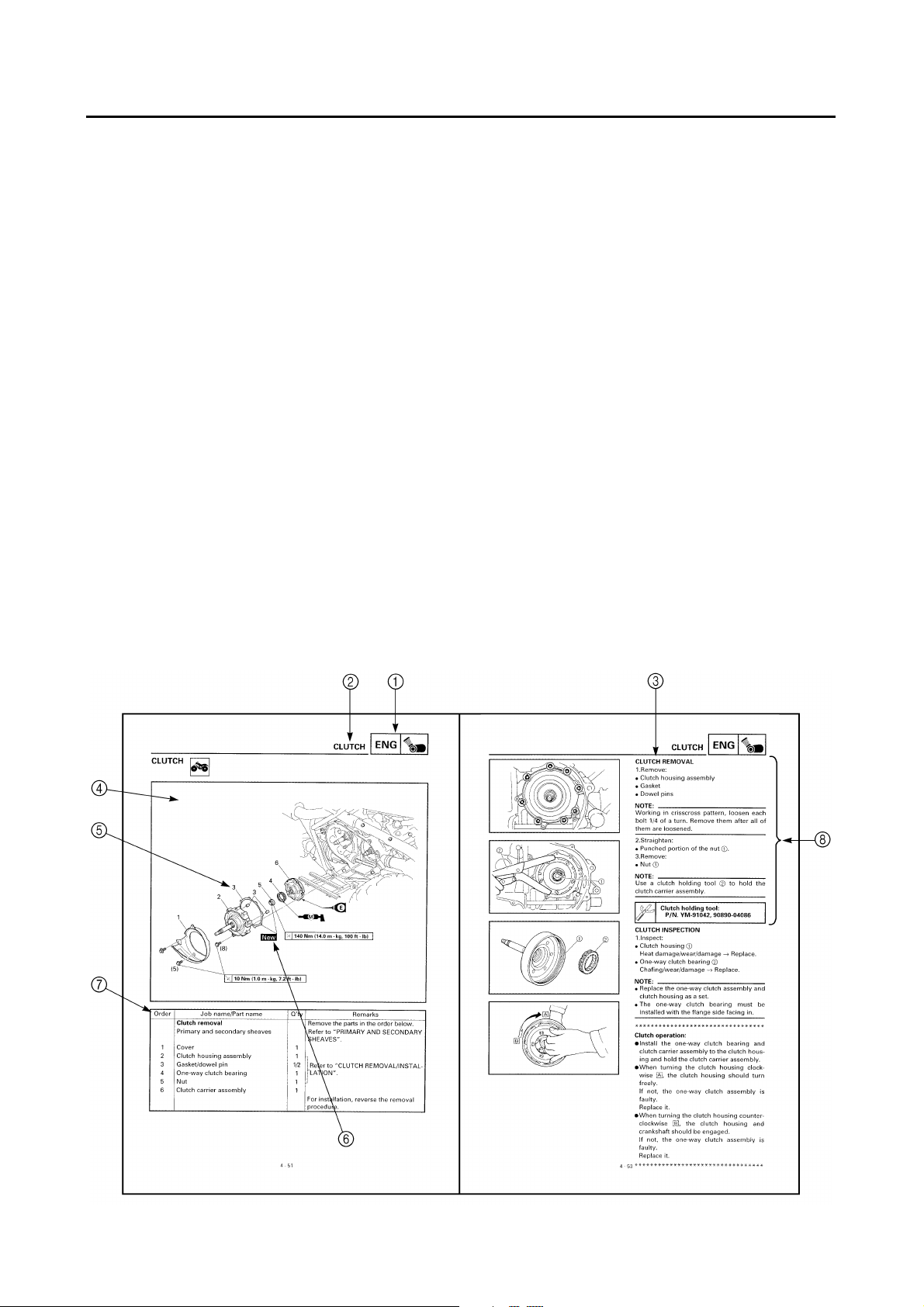
EXPLODED DIAGRAMS
To help identify parts and clarify procedure steps, there are exploded diagrams at the start of
each removal and disassembly section.
1. An easy-to-see exploded diagram 4 is provided for removal and disassembly jobs.
2. Numbers 5 are given in the order of the jobs in the exploded diagram. A number that is
enclosed by a circle indicates a disassembly step.
3. An explanation of jobs and notes is presented in an easy-to-read way by the use of symbol
marks 6 . The meanings of the symbol marks are given on the next page.
4. A job instruction chart 7 accompanies the exploded diagram, providing the order of jobs,
names of parts, notes in jobs, etc.
5. For jobs requiring more information, the step-by-step format supplements 8 are given in
addition to the exploded diagram and the job instruction chart.
1
2
3
4
5
6
7
8
9
0
A
B
C
D
E
F
G
I
J
K
L
M
N
12
GEN
INFO
34
SPEC
INSP
ADJ
56
COOL
78
DRIV
90
–+
ELEC
AB
ENG
CARB
CHAS
TRBL
SHTG
EB003000
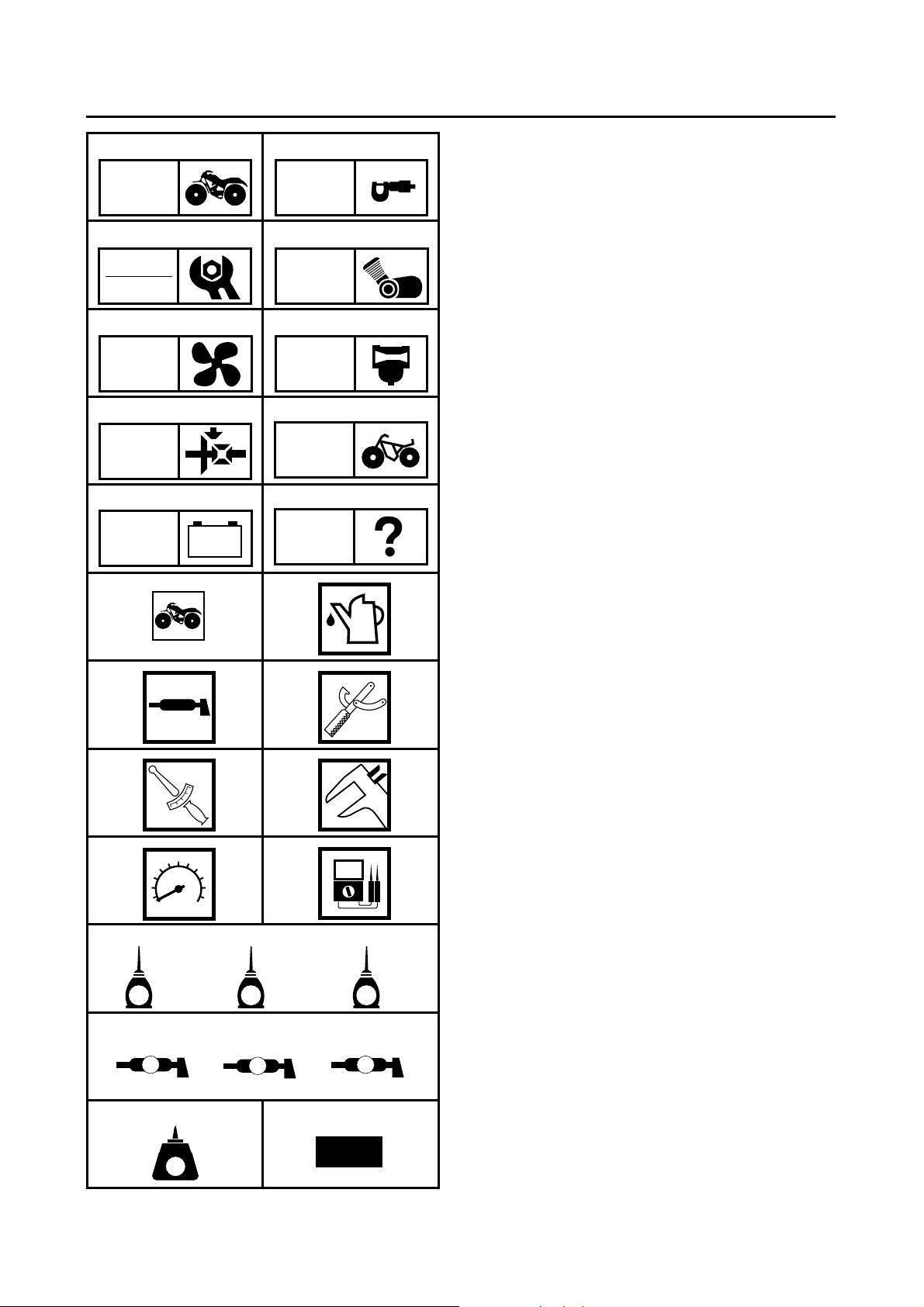
ILLUSTRATED SYMBOLS
Illustrated symbols 1 to 0 are printed on
the top right of each page and indicate the
subject of each chapter.
General information
Specifications
Periodic inspections and adjustments
Engine
Cooling system
Carburetion
Drive train
Chassis
Electrical
Troubleshooting
Illustrated symbols A to H are used to
identify the specifications appearing in the
text.
CD
EF
T
.
R
.
GH
IJK
E
LMN
B
O P
LT
G
LS
M
M
New
Can be serviced with engine mounted
Filling fluid
Lubricant
Special tool
Torque
Wear limit, clearance
Engine speed
H
, V, A
Ω
Illustrated symbols I to N in the exploded
diagrams indicate the types of lubricants
and lubrication points.
Apply engine oil
Apply gear oil
Apply molybdenum disulfide oil
Apply wheel bearing grease
Apply lightweight lithium-soap base grease
Apply molybdenum disulfide grease
Illustrated symbols O to P in the exploded
diagrams indicate where to apply a locking
agent O and when to install a new part P.
O Apply the locking agent (LOCTITE)
P Replace
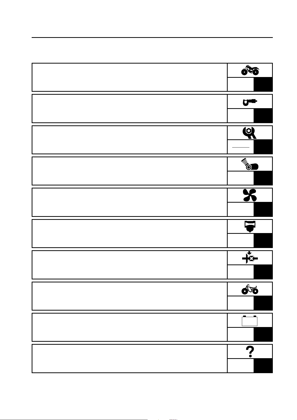
TABLE OF CONTENTS
GENERAL INFORMATION
SPECIFICATIONS
PERIODIC INSPECTION AND
ADJUSTMENTS
ENGINE
COOLING SYSTEM
GEN
INFO
SPEC
INSP
ADJ
ENG
COOL
1
2
3
4
5
CARBURETION
DRIVE TRAIN
CHASSIS
ELECTRICAL
TROUBLESHOOTING
CARB
DRIV
CHAS
–+
ELEC
TRBL
SHTG
6
7
8
9
10
GEN
INFO
1

GEN
INFO
CHAPTER 1.
GENERAL INFORMATION
MACHINE IDENTIFICATION .........................................................................1-1
VEHICLE IDENTIFICATION NUMBER ..................................................1-1
MODEL LABEL ......................................................................................1-1
FEATURES ....................................................................................................1-2
LIQUID COOLING ENGINE ...................................................................1-2
PARK POSITION ...................................................................................1-2
IMPORTANT INFORMATION .......................................................................1-3
PREPARATION FOR REMOVAL PROCEDURES .................................1-3
REPLACEMENT PARTS ........................................................................1-3
GASKETS, OIL SEALS AND O-RINGS ................................................1-3
LOCK WASHERS/PLATES AND COTTER PINS ..................................1-4
BEARINGS AND OIL SEALS ................................................................1-4
CIRCLIPS ...............................................................................................1-4
CHECKING OF CONNECTIONS ...................................................................1-5
SPECIAL TOOLS ...........................................................................................1-6

GEN
INFO
GEN
MACHINE IDENTIFICATION
GENERAL INFORMATION
MACHINE IDENTIFICATION
VEHICLE IDENTIFICATION NUMBER
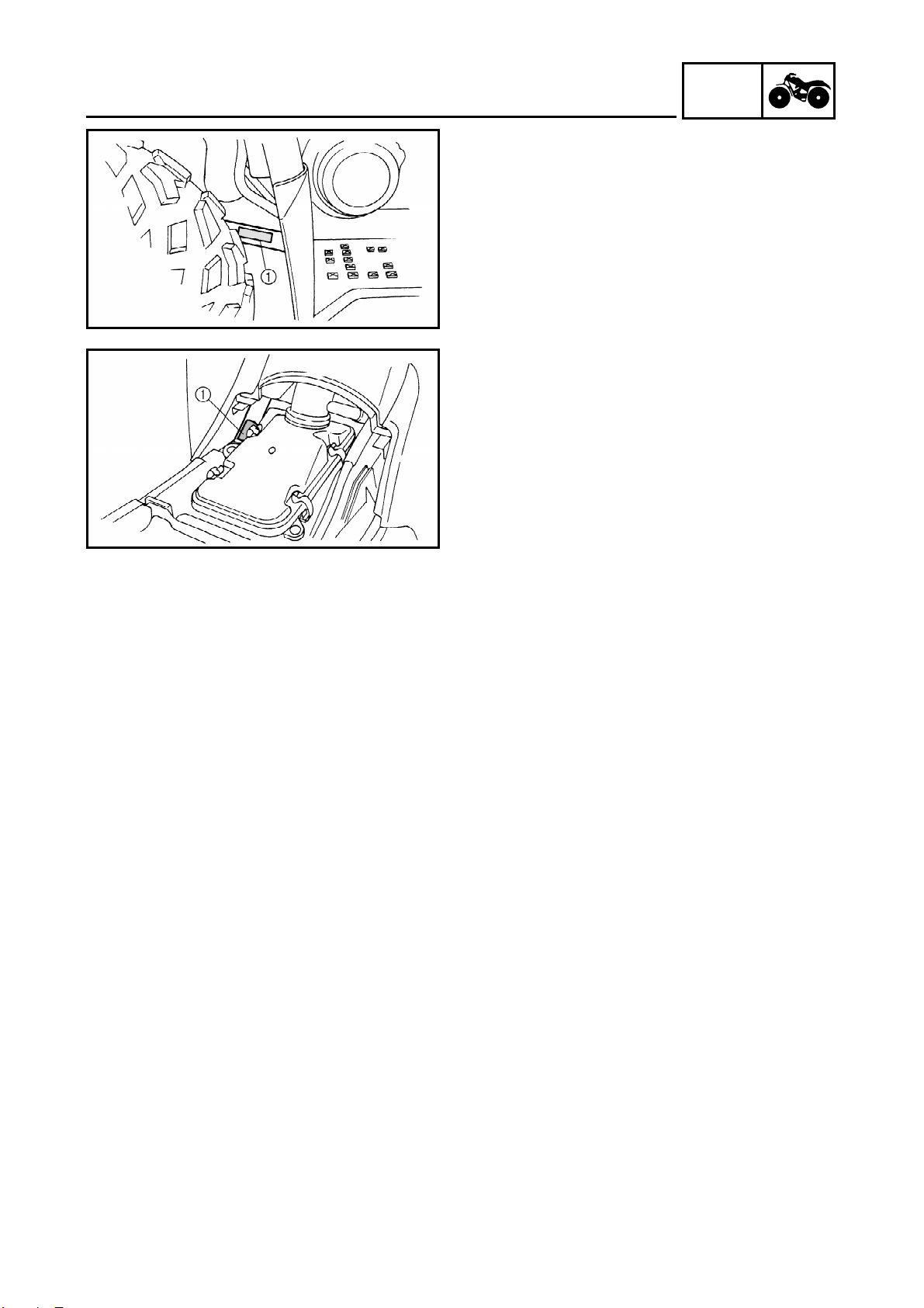
The vehicle identification number 1 is
stamped into the left side of the frame.
MODEL LABEL
The model label 1 is affixed to the frame.
This information will be needed to order
spare parts.
INFO
1 - 1
1
2
3
GEN
FEATURES
FEATURES
LIQUID COOLING ENGINE
Compact liquid cooled 45˚ inclined engine.
A liquid cooling system has been incorporated for stable power and engine endurance.
Radiator
Thermo switch
Fan motor
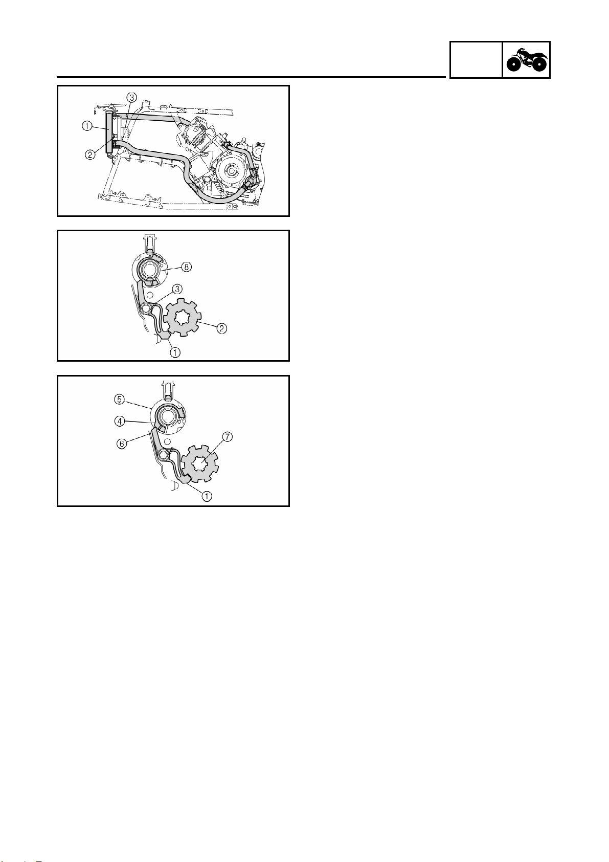
PARK POSITION
When the drive select lever is shifted into
the park position, a stopper lever is
engaged into the stopper gear preventing
the drive select lever and transmission from
moving.
INFO
When the drive select lever is at the “L”,
“H”, “N”, or “R” positions, the stopper
lever end 1 is moved away from the stopper gear 2 by the return spring 3 .
When the drive select lever is in the “P”
position, the lever cam 4 at the side of the
shift cam 5 lifts the stopper lever end 6
and the stopper lever end locks the drive
axle 7 .
When the stopper lever end 1 is not synchronized, a torsion spring 8 retains the
rotation force of the shift cam 5 until it is
synchronized.
1 - 2

IMPORTANT INFORMATION
EB101000
IMPORTANT INFORMATION
PREPARATION FOR REMOVAL
PROCEDURES
1.Remove all dirt, mud, dust and foreign
material before removal and disassembly.
2.Use proper tools and cleaning equipment.
Refer to the “SPECIAL TOOLS” section.
3.When disassembling the machine, always
keep mated parts together. This includes
gears, cylinder, piston and other parts that
have been “mated” through normal wear.
Mated parts must always be reused or
replaced as an assembly.
4.During machine disassembly, clean all
parts and place them in trays in the order
of disassembly. This will speed up assembly and allow for the correct installation of
all parts.
5.Keep all parts away from any source of
fire.
GEN
INFO
EB101010
REPLACEMENT PARTS
1.Use only genuine Yamaha parts for all
replacements. Use oil and grease recommended by Yamaha for all lubrication
jobs. Other brands may be similar in function and appearance, but inferior in quality.
EB101020
GASKETS, OIL SEALS AND O-RINGS
1.Replace all gaskets, seals and O-rings
when overhauling the engine. All gasket
surfaces, oil seal lips and O-rings must be
cleaned.
2.Properly oil all mating parts and bearings
during reassembly. Apply grease to the oil
seal lips.
1 - 3
1
1
4
IMPORTANT INFORMATION
EB101030
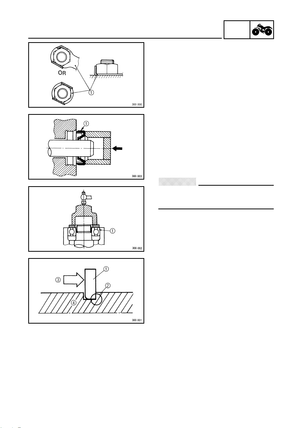
LOCK WASHERS/PLATES AND COTTER
PINS
1.Replace all lock washers/plates 1 and cotter pins after removal. Bend lock tabs
along the bolt or nut flats after the bolt or
nut has been tightened to specification.
EB101040
BEARINGS AND OIL SEALS
1.Install bearings and oil seals so that the
manufacturer’s marks or numbers are visible. When installing oil seals, apply a
light coating of lightweight lithium base
grease to the seal lips. Oil bearings liberally when installing, if appropriate.
Oil seal
GEN
INFO
CAUTION:
Do not use compressed air to spin the bearings dry. This will damage the bearing surfaces.
Bearing
EB101050
CIRCLIPS
1.Check all circlips carefully before reassembly. Always replace piston pin clips
after one use. Replace distorted circlips.
When installing a circlip 1 , make sure
that the sharp-edged corner 2 is positioned opposite the thrust 3 it receives.
See sectional view.
Shaft
1 - 4
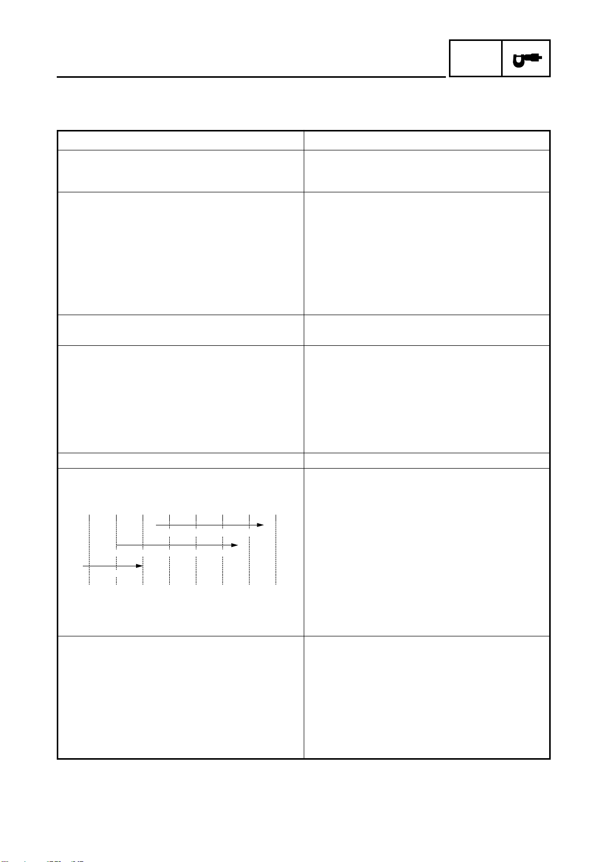
CHECKING OF CONNECTIONS
EB801000
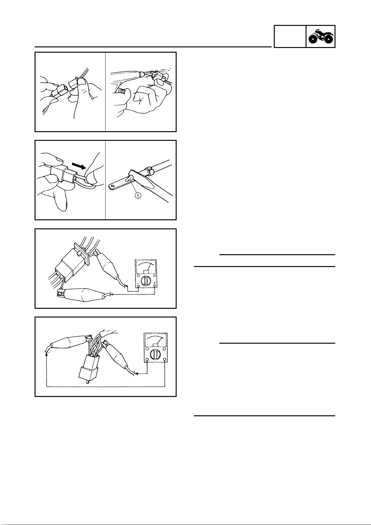
CHECKING OF CONNECTIONS
Check the connectors for stains, rust, moisture, etc.
1.Disconnect:
●
Connector
2.Check:
Connector
●
Moisture
blower.
Stains/rust
terminals several times.
3.Check:
Connector leads
●
Looseness
nect the terminals.
→
Dry each terminal with an air
→
Connect and disconnect the
→
Bend up the pin 1 and con-
GEN
INFO
4.Connect:
●
Connector terminals
OTE:
The two terminals “click” together.
5.Check:
Continuity (using a pocket tester)
●
OTE:
If there is no continuity, clean the termi-
●
nals.
●
When checking the wire harness be sure
to perform steps 1 to 3.
●
As a quick remedy, use a contact revitalizer available at most part stores.
Check the connector with a pocket tester
●
as shown.
1 - 5
GEN
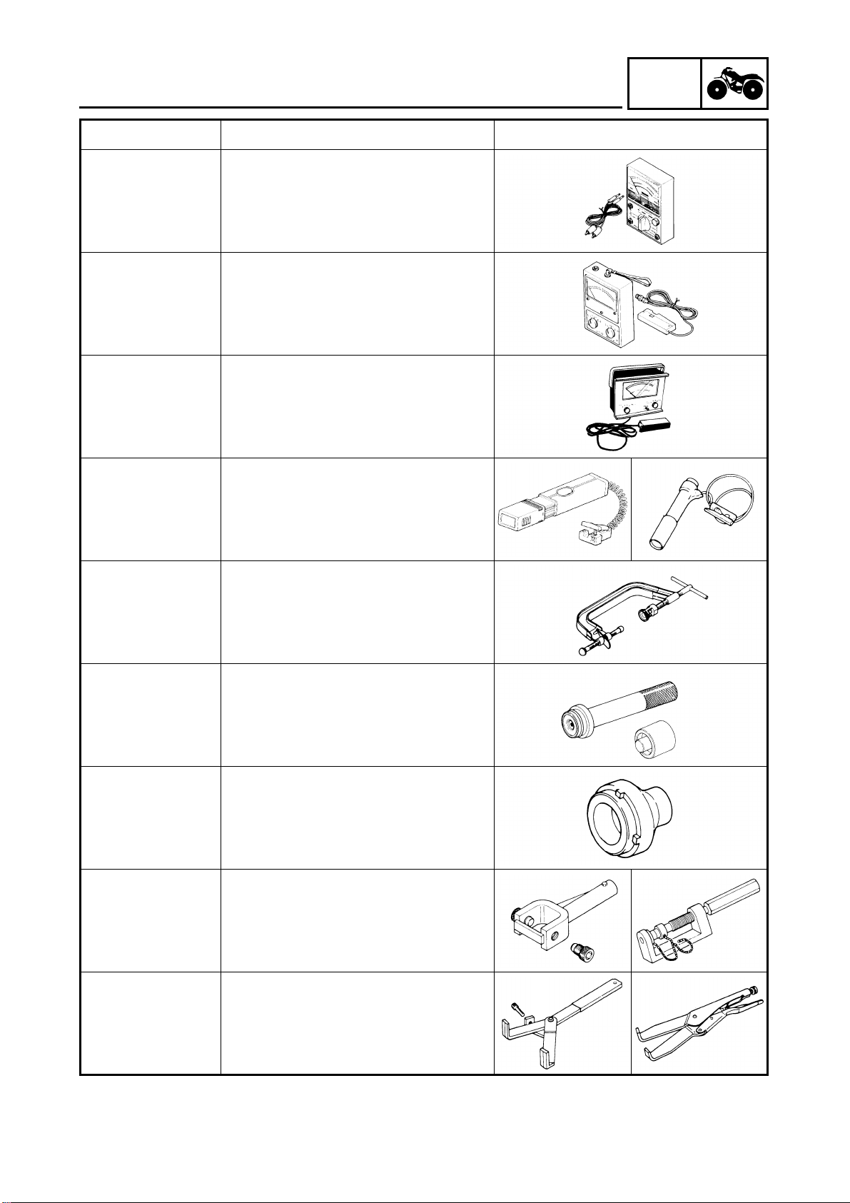
SPECIAL TOOLS
EB102001
SPECIAL TOOLS
The following special tools are necessary for complete and accurate tune-up and assembly.
Use only the appropriate special tools; this will help prevent damage caused by the use of
inappropriate tools or improvised techniques. Special tools may differ by shape and part
number from country to country. In such a case, two types are provided.
When placing an order, refer to the list provided below to avoid any mistakes.
For US and CDN
P/N. YM-, YU-, YS-, YK-, ACC-
Except for US and CDN
P/N. 90890-
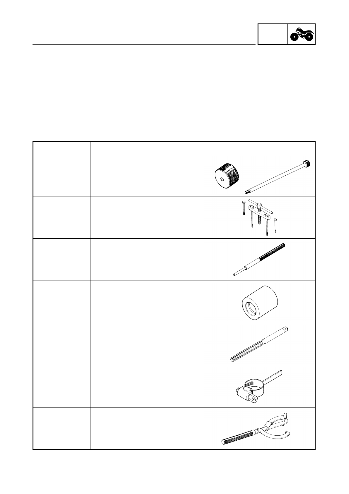
Tool No. Tool name/How to use Illustration
INFO
Bolt
90890-01083
Weight
90890-01084
Set
YU-01083-A
90890-01135
YU-01135-A
90890-01225
YM-01225-A
90890-04017
YM-04017
Slide hammer bolt (M6)/weight/set
These tools are used to remove the
rocker arm shaft.
Crankcase separating tool
This tool is used to separate the crankcase.
Valve guide remover (7.0 mm)
This tool is needed to remove and
install the valve guide.
Valve guide installer (7.0 mm)
This tool is needed to install the valve
guide.
Valve guide reamer (7.0 mm)
90890-01227
YM-01227
90890-01231
YM-01231
90890-01235
YU-01235
This tool is needed to rebore the new
valve guide.
Gear lash measurement tool
This tool is used to measure the gear
lash.
Rotor holding tool
This tool is needed to hold the starter
puller when removing/installing the
starter puller bolt or camshaft sprocket
bolts.
1 - 6
GEN
SPECIAL TOOLS
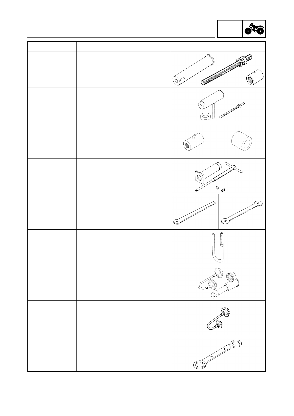
Tool No. Tool name/How to use Illustration
Buffer boss installer set
Kit
90890-04088
Bolt
90890-01275
YU-90050
Crankshaft installer bolt
These tools are used to install the
crankshaft.
Crankshaft installer set
These tools are used to install the
crankshaft.
INFO
Adapter
YM-33279
Spacer
90890-04060
YM-90070-A
90890-01304
YU-01304
90890-01311
YU-08035
90890-01312
YM-01312-A
Adapter (#11)
Spacer (crankshaft installer)
These tools are used to install the
crankshaft.
Piston pin puller
This tool is used to remove the piston
pin.
Tappet adjusting tool (3 mm)
This tool is necessary for adjusting the
valve clearance.
Fuel level gauge
This gauge is used to measure the fuel
level in the float chamber.
Radiator cap tester
90890-01325
YU-24460-01
90890-01352
YU-33984
90890-01348
This tool is used to check the cooling
system.
Adapter
This tool is used to check the cooling
system.
Locknut wrench
This tool is needed when removing or
installing the secondary sheave
spring.
1 - 7
GEN
SPECIAL TOOLS
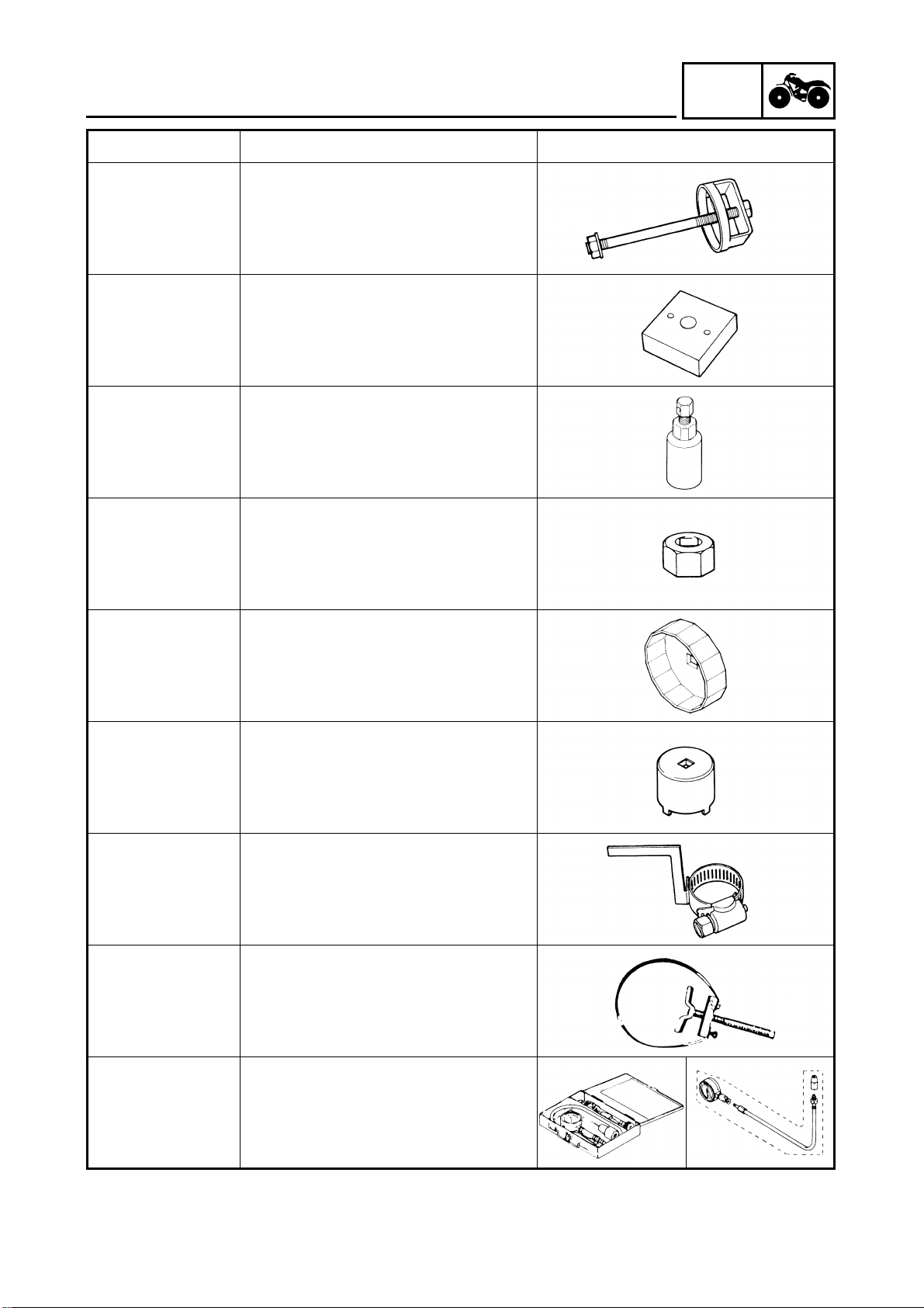
Tool No. Tool name/How to use Illustration
Sheave spring compressor
INFO
90890-04134
YM-04134
90890-04135
YM-04135
90890-01404
YM-01404
90890-01327
YM-01327
90890-01426
YU-38411
This tool is needed when removing or
installing the secondary sheave
spring.
Sheave fixed block
This tool is needed when removing or
installing the secondary sheave
spring.
Flywheel puller
These tools are needed to remove the
rotor.
Damper rod holder (30 mm)
This tool is needed to loosen and
tighten the steering stem bearing
retainer.
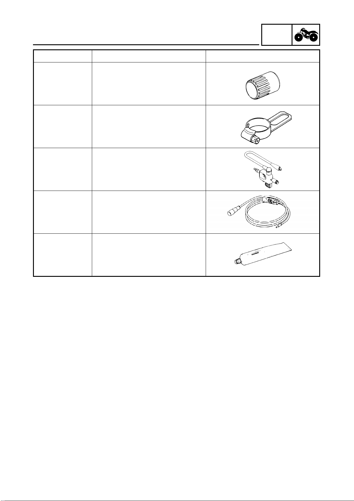
Oil filter wrench
This tool is needed to loosen or tighten
the oil filter cartridge.
90890-01430
YM-38404
90890-01467
YM-01467
90890-01475
YM-01475
90890-01701
YU-01880
Set
90890-03081
YU-33223
Adapter
90890-04082
YU-33223-3
Ring nut wrench
This tool is needed to removing and
installing the middle driven shaft bearing retainer.
Gear lash measurement tool
This tool is used to measure the gear
lash.
Sheave holder
This tool is needed to hold the primary
sheave when removing or installing
the sheave bolts.
Compression gauge set
Adapter
These tools are needed to measure
engine compression.
1 - 8
GEN
SPECIAL TOOLS
Tool No. Tool name/How to use Illustration
Pocket tester
90890-03112
YU-03112
This instrument is needed for checking
the electrical system.
Engine tachometer
90890-03113
This tool is needed for observing
engine rpm.
Inductive tachometer
YU-8036-A
This tool is needed for observing
engine rpm.
Timing light
INFO
90890-03141
YM-33277-A
90890-04019
YM-04019
Middle driven shaft
bearing driver
90890-04058
YM-04058-1
Mechanical seal
installer
90890-04078
YM-33221
90890-04050
YM-04050
90890-04062
YM-04062
This tool is necessary for checking
ignition timing.
Valve spring compressor
This tool is needed to remove and
install the valve assemblies.
Middle driven shaft bearing driver
Mechanical seal installer
These tools are used to install the
water pump seal.
Bearing retainer wrench
This tool is needed when removing or
installing the final drive shaft bearing
retainer.
Universal joint holder
This tool is needed when removing or
installing the universal joint yoke nut.
90890-04086
YM-91042
Clutch holding tool
This tool is needed to hold the clutch
carrier when removing or installing the
carrier nut.
1 - 9
GEN
SPECIAL TOOLS
Tool No. Tool name/How to use Illustration
Bearing retainer wrench
INFO
90890-04128
YM-04128
90890-04129
YM-04129
90890-06754
YM-34487
Bond
90890-85505
Sealant
ACC-11001-05-01
This tool is needed when removing or
installing the middle driven pinion
gear bearing retainer.
Pinion gear fix clamp
This tool is used to hold the shift cam.
Ignition checker
This instrument is necessary for checking the ignition system components.
Dynamic spark tester
This instrument is necessary for checking the ignition system components.
Yamaha bond No. 1215
Sealant (Quick Gasket®)
This sealant (bond) is used on crankcase mating surfaces, etc.
1 - 10
SPEC
2

SPEC
CHAPTER 2.
SPECIFICATIONS
GENERAL SPECIFICATIONS .........................................................................2-1
MAINTENANCE SPECIFICATIONS ...............................................................2-5
ENGINE ..................................................................................................2-5
CHASSIS ..............................................................................................2-15
ELECTRICAL .........................................................................................2-19
HOW TO USE THE CONVERSION TABLE ................................................2-21
GENERAL TORQUE SPECIFICATIONS ......................................................2-21
LUBRICATION POINTS AND LUBRICANT TYPES ...................................2-22
ENGINE ...............................................................................................2-22
COOLANT FLOW DIAGRAMS ...................................................................2-23
OIL FLOW DIAGRAMS ...............................................................................2-25
CABLE ROUTING ........................................................................................2-28

SPEC
GENERAL SPECIFICATIONS
SPECIFICATIONS
GENERAL SPECIFICATIONS
Item Standard
Model code: 5GH3 : (For CDN)
5GH4 : (For GB, F, CH)
5GH5 : (For Oceania)
Dimensions:
Overall length 1,965 mm (77.36 in)
Overall width 1,070 mm (42.13 in)
Overall height 1,120 mm (44.09 in)
Seat height 820 mm (32.28 in)
Wheelbase 1,225 mm (48.23 in)
Minimum ground clearance 245 mm (9.65 in)
Minimum turning radius 3,000 mm (118.11 in)
Basic weight:
With oil and full fuel tank 262 kg (578 lb)
Engine:
Engine type Liquid-cooled 4-stroke, SOHC
Cylinder arrangement Forward-inclined single cylinder
3
Displacement 401 cm
Bore × stroke 84.5 × 71.5 mm (3.33 × 2.81 in)
Compression ratio 10.5 : 1
Starting system Electric and recoil starter
Lubrication system: Wet sump
Oil type or grade:
Engine oil
SPEC
0° 10° 30° 50° 70° 90° 110°
YAMALUBE 4 (20W40) or SAE 20W40
YAMALUBE 4 (10W30) or SAE 10W30
SAE 5W30
-20° -10° 0° 10° 20° 30° 40°
130°F
API service SE, SF, SG type or higher
50°C
Final gear oil SAE 80API “GL-4” Hypoid Gear Oil
Differential gear oil SAE 80API “GL-4” Hypoid Gear Oil
Oil capacity:
Engine oil
Periodic oil change 2.3 L (2.0 lmp qt, 2.4 US qt)
With oil filter replacement 2.4 L (2.1 lmp qt, 2.5 US qt)
Total amount 2.6 L (2.3 lmp qt, 2.7 US qt)
Final gear case oil
Periodic oil change 0.19 L (0.17 lmp qt, 0.20 US qt)
Total amount 0.22 L (0.19 lmp qt, 0.23 US qt)
2 - 1
GENERAL SPECIFICATIONS
Item Standard
Differential gear case oil
Periodic oil change 0.35 L (0.31 lmp qt, 0.37 US qt)
Total amount 0.40 L (0.35 lmp qt, 0.42 US qt)
Radiator capacity (including all routes) 1.1 L (0.97 lmp qt, 1.16 US qt)
Air filter: Wet type element
Fuel:
Type
Fuel tank capacity 15 L (3.3 lmp gal, 3.9 US gal)
Fuel reserve amount 4.5 L (0.99 lmp gal, 1.19 US gal)
Carburetor:
Type/quantity BSR33/1
Manufacturer MIKUNI
Spark plug:
Type/manufacturer DR8EA/NGK (For CDN, GB, F, CH)
Spark plug gap 0.6 ~ 0.7 mm (0.02 ~ 0.03 in)
Clutch type: Wet, centrifugal automatic
Transmission:
Primary reduction system V-belt
Secondary reduction system Spur gear
Secondary reduction ratio 39/24 × 24/18 × 33/9 (7.944)
Transmission type V-belt automatic
Operation Left hand operation
Single speed automatic 2.55 ~ 0.75 : 1
Sub transmission ratio low 45/16 (2.813)
high 38/23 (1.652)
Reverse gear 29/17 (1.706)
Chassis:
Frame type Steel tube frame
Caster angle 4.0˚
Camber angle 1˚
Kingpin angle 11˚
Kingpin offset 1 mm (0.04 in)
Trail 21 mm (0.83 in)
Tread (STD) front 850 mm (33.46 in)
rear 825 mm (32.48 in)
Toe-in 0 ~ 10 mm (0 ~ 0.39 in)
Tire:
Type Tubeless
Size front AT25 × 8–12
rear AT25 × 10–12
Regular unleaded gasoline (For CDN, GB, F, CH)
Unleaded fuel only (For Oceania)
D8EA/NGK (For Oceania)
X24ES-U/DENSO (For Oceania)
SPEC
2 - 2

GENERAL SPECIFICATIONS
Item Standard
Manufacturer front DUNLOP (For CDN, GB, F, CH)
CHENG SHIN (For Oceania)
rear DUNLOP (For CDN, GB, F, CH)
CHENG SHIN (For Oceania)
Type front KT123 (For CDN, GB, F, CH)
C828 (For Oceania)
rear KT127 (For CDN, GB, F, CH)
C828 (For Oceania)
SPEC
2 - 3
GENERAL SPECIFICATIONS
Item Standard
Tire pressure (cold tire):
Maximum load* 210 kg (463 lb)
Off-road riding front 22 ~ 28 kPa (0.22 ~ 0.28 kg/cm
rear 22 ~ 28 kPa (0.22 ~ 0.28 kg/cm
*Load in total weight of rider accessories
Brake:
Front brake type Dual disc brake
operation Right hand operation
Rear brake type Single disc brake
operation Left hand and right foot operation
Suspension:
Front suspension Double wishbone
Rear suspension Swingarm (monocross)
Shock absorber:
Front shock absorber Coil spring/oil damper
Rear shock absorber Coil spring/oil damper
Wheel travel:
Front wheel travel 160 mm (6.30 in)
Rear wheel travel 180 mm (7.09 in)
Electrical:
Ignition system C.D.I.
Generator system A.C. magneto
Battery type YTX20L-BS
Battery capacity 12 V 18 AH
Headlight type: Krypton bulb
Bulb wattage × quantity:
Headlight 12 V 30 W/30 W × 2
Tail light 12 V 7.5 W × 1
Meter light 14 V 3.4 W × 1
Indicator lights
Neutral 14 V 1.7 W × 1
Reverse 14 V 1.7 W × 1
Coolant temperature 14 V 1.7 W × 1
Four-wheel drive 14 V 1.7 W × 1
Park 14 V 1.7 W × 1
SPEC
2
, 3.2 ~ 4.0 psi)
2
, 3.2 ~ 4.0 psi)
2 - 4
MAINTENANCE SPECIFICATIONS
SPEC
MAINTENANCE SPECIFICATIONS
ENGINE
Item Standard Limit
Cylinder head:
Warp limit ---- 0.03 mm
(0.0012 in)
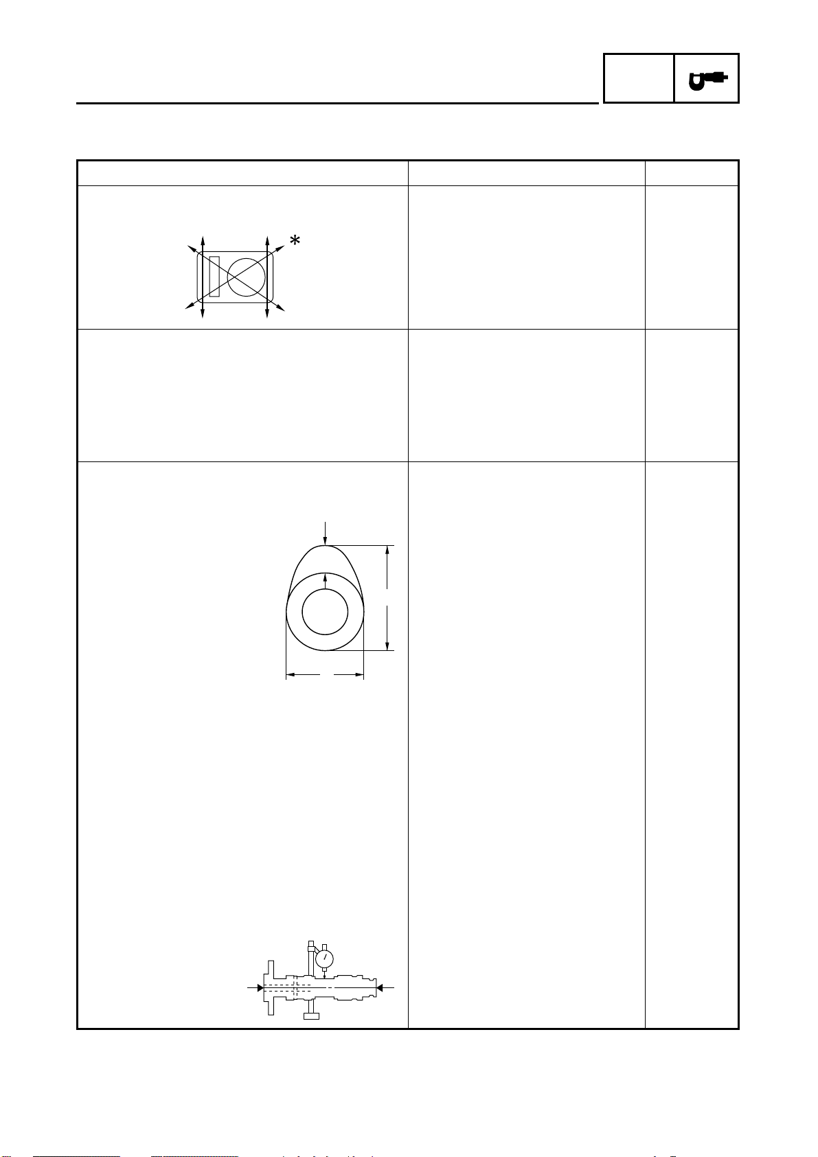
Cylinder:
Bore size 84.500 ~ 84.510 mm
(3.3268 ~ 3.3272 in)
Taper limit ---- 0.05 mm
Out of round limit ---- 0.01 mm
Camshaft:
Drive method Chain drive (Left) ----
Cam dimensions
84.600 mm
(3.3307 in)
(0.0016 in)
(0.0004 in)
C
A
B
Intake “A” 40.62 ~ 40.72 mm
(1.5992 ~ 1.6031 in)
“B” 32.18 ~ 32.28 mm
(1.2669 ~ 1.2709 in)
“C” 8.61 ~ 8.73 mm
(0.3390 ~ 0.3437 in)
Exhaust “A” 40.62 ~ 40.72 mm
(1.5992 ~ 1.6031 in)
“B” 32.18 ~ 32.28 mm
(1.2669 ~ 1.2709 in)
“C” 8.61 ~ 8.73 mm
(0.3390 ~ 0.3437 in)
Camshaft runout limit ---- 0.03 mm
40.52 mm
(1.5953 in)
32.08 mm
(1.2630 in)
----
40.52 mm
(1.5953 in)
32.08 mm
(1.2630 in)
----
(0.0012 in)
2 - 5
MAINTENANCE SPECIFICATIONS
SPEC
Item Standard Limit
Cam chain:
Cam chain type/No. of links 92RH2015/116 ----
Cam chain adjustment method Automatic ---Rocker arm/rocker arm shaft:
Shaft outside diameter 11.981 ~ 11.991 mm
(0.4717 ~ 0.4721 in)
Arm-to-shaft clearance 0.009 ~ 0.037 mm
(0.0004 ~ 0.0015 in)
Valve, valve seat, valve guide:
Valve clearance (cold) IN 0.06 ~ 0.10 mm
(0.0024 ~ 0.0039 in)
EX 0.16 ~ 0.20 mm
(0.0063 ~ 0.0079 in)
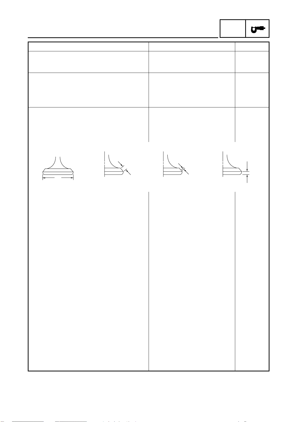
Valve dimensions
A
Head Diameter
Face Width
B
Seat Width
C
Margin Thickness
11.951 mm
(0.4705 in)
0.08 mm
(0.0031 in)
----
----
D
“A” head diameter IN 39.9 ~ 40.1 mm
(1.5708 ~ 1.5787 in)
EX 33.9 ~ 34.1 mm
(1.3346 ~ 1.3425 in)
“B” face width IN 2.26 mm (0.0890 in) ----
EX 2.26 mm (0.0890 in) ----
“C” seat width IN 1.2 ~ 1.4 mm
(0.0472 ~ 0.0551 in)
EX 1.2 ~ 1.4 mm
(0.0472 ~ 0.0551 in)
“D” margin thickness IN 1.0 ~ 1.4 mm
(0.0394 ~ 0.0551 in)
EX 0.8 ~ 1.2 mm
(0.0314 ~ 0.0472 in)
Stem outside diameter IN 6.975 ~ 6.990 mm
(0.2746 ~ 0.2752 in)
EX 6.955 ~ 6.970 mm
(0.2738 ~ 0.2744 in)
Guide inside diameter IN 7.000 ~ 7.012 mm
(0.2756 ~ 0.2761 in)
EX 7.000 ~ 7.012 mm
(0.2756 ~ 0.2761 in)
Stem-to-guide clearance IN 0.010 ~ 0.037 mm
(0.0004 ~ 0.0015 in)
EX 0.030 ~ 0.057 mm
(0.0012 ~ 0.0022 in)
----
----
1.6 mm
(0.0630 in)
1.6 mm
(0.0630 in)
----
----
6.950 mm
(0.2736 in)
6.915 mm
(0.2722 in)
7.030 mm
(0.2768 in)
7.030 mm
(0.2768 in)
0.08 mm
(0.0031 in)
0.10 mm
(0.0039 in)
2 - 6
MAINTENANCE SPECIFICATIONS
Item Standard Limit
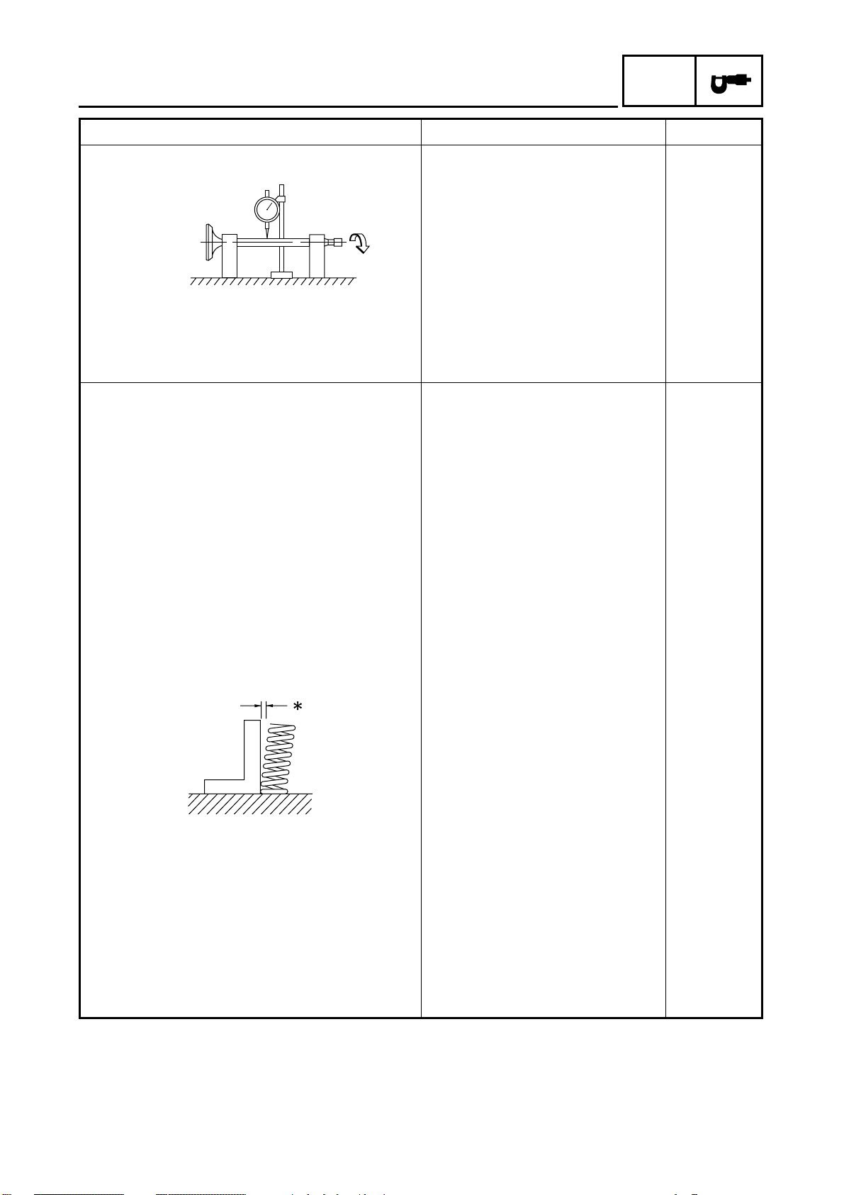
Stem runout limit ---- 0.01 mm
Valve seat width IN 1.2 ~ 1.4 mm
(0.0472 ~ 0.0551 in)
EX 1.2 ~ 1.4 mm
(0.0472 ~ 0.0551 in)
Valve spring:
Inner spring
Free length IN 39.9 mm (1.57 in) 37.9 mm
EX 39.9 mm (1.57 in) 37.9 mm
Set length (valve closed) IN 33.6 mm (1.32 in) ----
EX 33.6 mm (1.32 in) ----
Compressed pressure
(installed) IN 104.9 ~ 120.6 N (10.70 ~
12.30 kg, 23.58 ~ 27.11 lb)
EX 104.9 ~ 120.6 N (10.70 ~
12.30 kg, 23.58 ~ 27.11 lb)
Tilt limit IN 2.5˚/1.6 mm
*
EX 2.5˚/1.6 mm
SPEC
(0.0004 in)
----
----
(1.49 in)
(1.49 in)
----
----
(2.5˚/0.06 in)
(2.5˚/0.06 in)
Direction of winding
(top view) IN Counterclockwise ----
EX Counterclockwise ----
Outer spring
Free length IN 43.27 mm (1.70 in) 41.27 mm
(1.62 in)
EX 43.27 mm (1.70 in) 41.27 mm
(1.62 in)
Set length (valve closed) IN 36.6 mm (1.44 in) ----
EX 36.6 mm (1.44 in) ----
2 - 7
MAINTENANCE SPECIFICATIONS
Item Standard Limit
Compressed pressure
(installed) IN 235.4 ~ 251.1 N (24.00 ~
25.60 kg, 52.92 ~ 56.45 lb)
EX 235.4 ~ 251.1 N (24.00 ~
25.60 kg, 52.92 ~ 56.45 lb)
Tilt limit IN 2.5˚/1.6 mm
Direction of winding
(top view) IN Clockwise ----
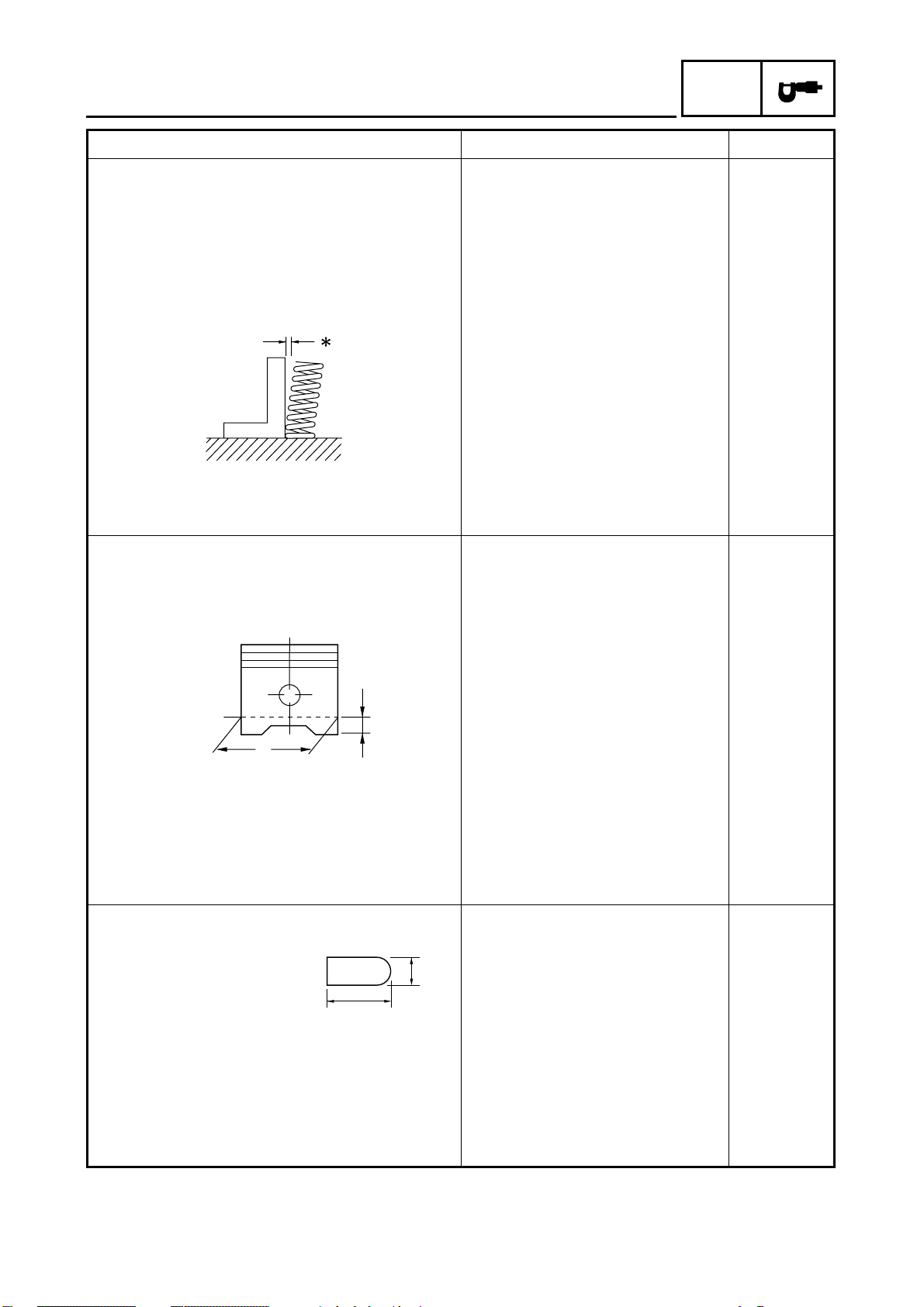
Piston:
Piston to cylinder clearance 0.040 ~ 0.065 mm
Piston size “D” 84.445 ~ 84.460 mm
*
EX 2.5˚/1.6 mm
EX Clockwise ----
(0.0016 ~ 0.0026 in)
(3.3246 ~ 3.3252 in)
SPEC
----
----
(2.5˚/0.06 in)
(2.5˚/0.06 in)
0.15 mm
(0.0059 in)
----
H
D
Measuring point “H” 5 mm (0.20 in) ----
Piston off-set 0.5 mm (0.0200 in) ----
Piston pin bore inside diameter 20.004 ~ 20.015 mm
(0.7876 ~ 0.7880 in)
Piston pin outside diameter 19.993 ~ 20.000 mm
(0.7871 ~ 0.7874 in)
Piston rings:
Top ring
B
T
Type Barrel ---Dimensions (B × T) 1.2 × 3.1 mm
(0.0472 × 0.1220 in)
End gap (installed) 0.2 ~ 0.4 mm
(0.0079 ~ 0.0157 in)
Side clearance (installed) 0.03 ~ 0.08 mm
(0.0012 ~ 0.0031 in)
20.045 mm
(0.7892 in)
19.973 mm
(0.7863 in)
----
0.65 mm
(0.0256 in)
0.13 mm
(0.0051 in)
2 - 8
 Loading...