

Page 1

2000
YFM40FPM
YFM400FW
(
M
)
4GB-AE4
SUPPLEMENTARY
SERVICE MANUAL
Page 2

FOREWORD
This Supplementary Service Manual has been prepared to introduce new service and new data for
the YFM40FPM/YFM400FW(M) 2000. For complete information on service procedures, it is necessary to use this Supplementary Service Manual together with the following manual.
YFM400FW ’93 SERVICE MANUAL: 4GB-ME1
YFM400FW ’93 SUPPLEMENTARY SERVICE MANUAL: 4GB-AE1
YFM400FW(H) ’96 SUPPLEMENTARY SERVICE MANUAL: 4GB-AE2
YFM40FPM/YFM400FW(M) 2000
SUPPLEMENTARY
SERVICE MANUAL
1999 by Yamaha Motor Co., Ltd.
1st Edition, December 1999
All rights reserved. Any reproduction
or unauthorized use without the written
permission of Yamaha Motor Co., Ltd.
is expressly prohibited.
Page 3
NOTICE
This manual was written by the Yamaha Motor Company, Ltd. primarily for use by Yamaha dealers
and qualified mechanics. It is not possible to put an entire mechanic’s education into one manual,
so persons using this book to perform maintenance and repairs on Yamaha machines should have
a basic understanding of the mechanical concepts and the procedures inherent in machine repair
technology. Without such knowledge, attempted repairs or service to the machine may render it
unfit to use and/or unsafe.
Yamaha Motor Company, Ltd. is continually striving to improve all models manufactured by
Yamaha. Modifications and significant changes in specifications or procedures will be forwarded to
all Authorized Yamaha dealers and will, where applicable, appear in future editions of this manual.
NOTE:
Designs and specifications are subject to change without notice.
PARTICULARLY IMPORTANT INFORMATION
This material is distinguished by the following notation.
The Safety Alert Symbol means ATTENTION! BECOME ALERT! YOUR
SAFETY IS INVOLVED!
WARNING
CAUTION:
TE:
Failure to follow WARNING instructions could result in severe injury or
death to the machine operator, a bystander, or a person inspecting or
repairing the machine.
A CAUTION indicates special precautions that must be taken to avoid damage to the machine.
A NOTE provides key information to make procedures easier or clearer.
Page 4
”.
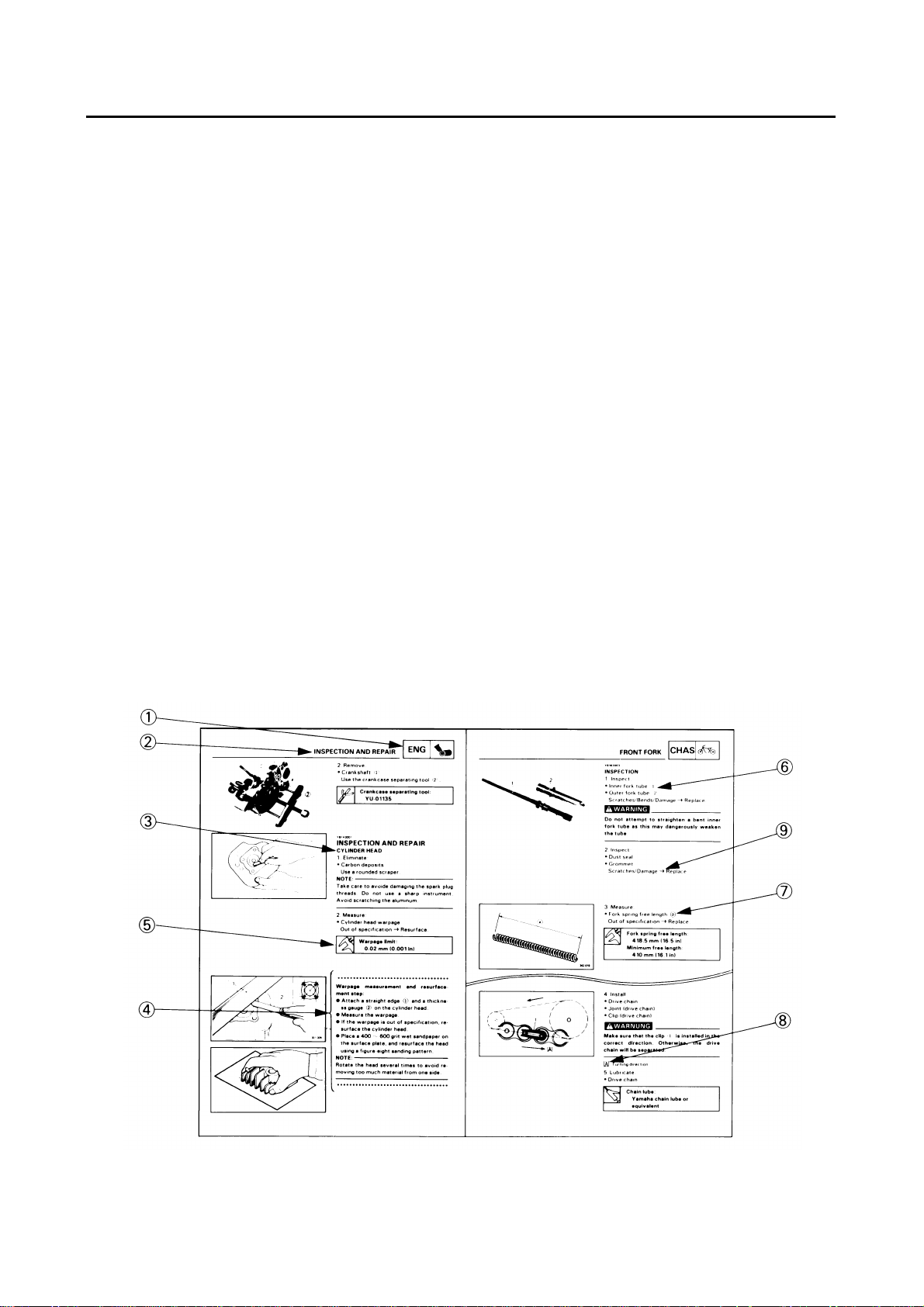
HOW TO USE THIS MANUAL
CONSTRUCTION OF THIS MANUAL
This manual consists of chapters for the main categories of subjects. (See “Illustrated symbols”)
1st title
2nd title
1
: This is a chapter with its symbol on the upper right of each page.
2
: This title appears on the upper of each page on the left of the chapter sym-
bol. (For the chapter “Periodic inspection and adjustment” the 3rd title
appears.)
3rd title
3
: This is a final title.
MANUAL FORMAT
All of the procedures in this manual are organized in a sequential, step-by-step format. The information has been compiled to provide the mechanic with an easy to read, handy reference that contains
comprehensive explanations of all disassembly, repair, assembly, and inspections.
A set of particularly important procedure 4 is placed between a line of asterisks “
cedure preceded by “
●
” with each pro-
*
IMPORTANT FEATURES
Data and a special tool are framed in a box preceded by a relevant symbol
●
●
An encircled numeral
alignment mark
●
A condition of a faulty component will precede an arrow symbol
7
6
indicates a part name, and an encircled alphabetical letter data or an
, the others being indicated by an alphabetical letter in a box
9
and the course of action will
5
.
8
.
follow it.
EXPLODED DIAGRAM
Each chapter provides exploded diagrams before each disassembly section for ease in identifying
correct disassembly and assembly procedures.
Page 5
12
GEN
SPEC
INFO
34
INSP
ENG
ADJ
56
CARB
78
CHAS
90
DRIV
–+
ELEC
TRBL
SHTG
AB
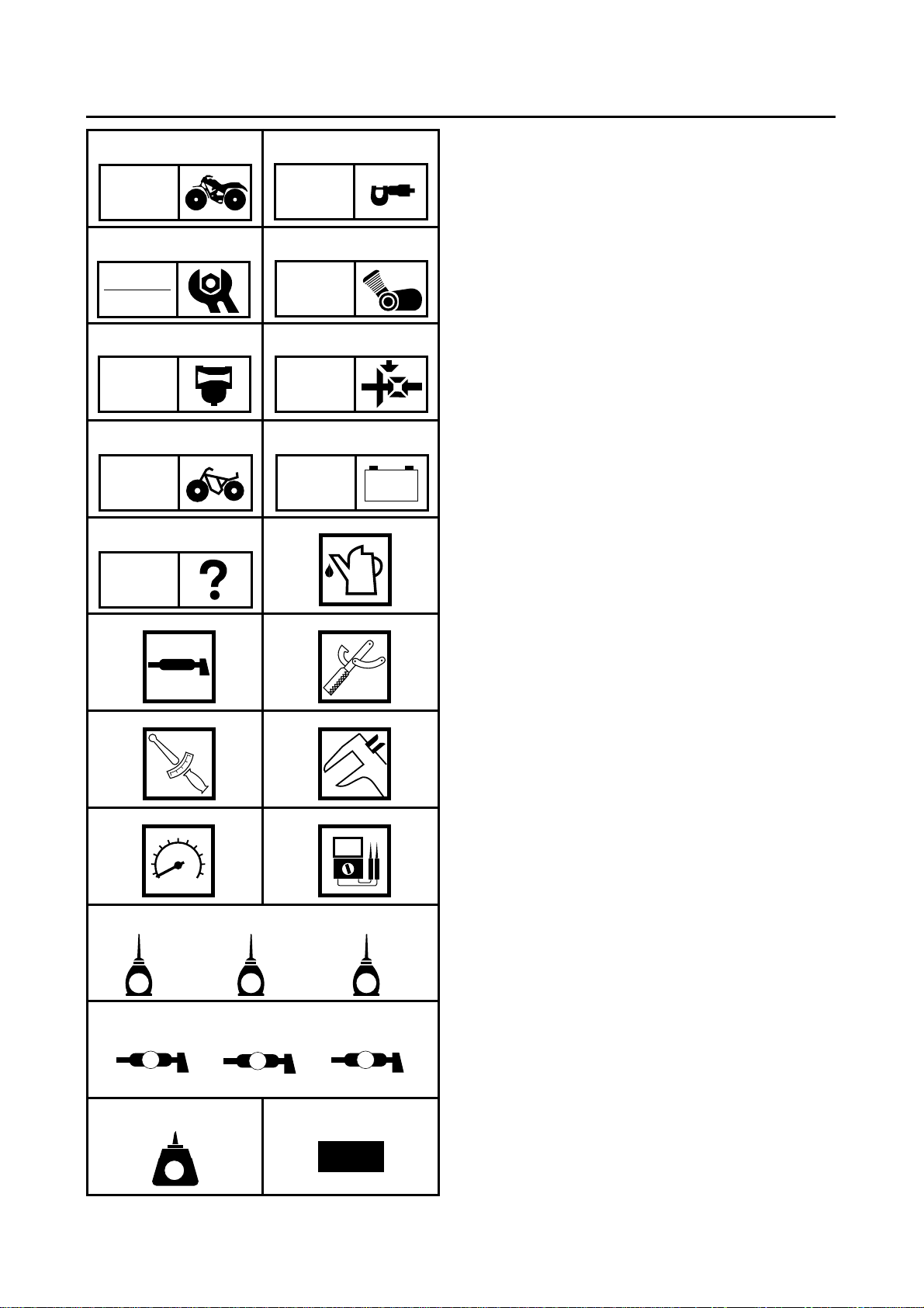
ILLUSTRATED SYMBOLS
(Refer to the illustration)
Illustrated symbols
thumb tabs to indicate the chapter’s number
and content.
1
General information
2
Specifications
3
Periodic inspections and adjustments
4
Engine overhaul
5
Carburetion
6
Drive train
7
Chassis
8
Electrical
9
Troubleshooting
Illustrated symbols
the specifications appearing in the text.
0
Filling fluid
A
Lubricant
B
Special tool
C
Tightening
D
Wear limit, clearance
E
Engine speed
F
, V, A
Ω
0
1
to
9
are designed as
to
F
are used to identify
CD
T
.
R
.
EF
GHI
E
JKL
B
M N
LT
G
LS
M
M
New
Illustrated symbols
G
to
N
in the exploded
diagrams indicate grade of lubricant and location of lubrication point.
G
Apply engine oil
H
Apply gear oil
I
Apply molybdenum disulfide oil
J
Apply wheel bearing grease
K
Apply lightweight lithium-soap base grease
L Apply molybdenum disulfide grease
M Apply the locking agent (LOCTITE®)
N Use new one
Page 6

CONTENTS
GENERAL INFORMATION ..............................................................................1
MACHINE IDENTIFICATION .................................................................... 1
VEHICLE IDENTIFICATION NUMBER................................................. 1
MODEL LABEL.....................................................................................1
SPECIFICATIONS
GENERAL SPECIFICATIONS..................................................................2
MAINTENANCE SPECIFICATIONS ......................................................... 4
ENGINE ................................................................................................ 4
CHASSIS .............................................................................................. 5
ELECTRICAL........................................................................................6
CABLE ROUTING.....................................................................................8
PERIODIC INSPECTIONS AND ADJUSTMENTS
INTRODUCTION.....................................................................................15
PERIODIC MAINTENANCE/LUBRICATION .......................................... 15
SEAT, CARRIERS, FENDERS AND FUEL TANK..................................17
REMOVAL........................................................................................... 17
INSTALLATION................................................................................... 20
ENGINE................................................................................................... 22
STARTER LEVER FREE PLAY ADJUSTMENT................................. 22
CHASSIS................................................................................................. 23
FRONT BRAKE PAD INSPECTION...................................................23
AIR BLEEDING (HYDRAULIC BRAKE SYSTEM)..............................23
REAR SHOCK ABSORBER ADJUSTMENT......................................24
TIRE INSPECTION............................................................................. 25
ELECTRICAL..........................................................................................27
BATTERY INSPECTION..................................................................... 27
FUSE INSPECTION............................................................................ 32
............................................................................................2
.........................................15
ENGINE OVERHAUL
ENGINE ASSEMBLY AND ADJUSTMENT ............................................34
VALVE, CAMSHAFT AND ROCKER ARM.........................................34
.....................................................................................34
Page 7

CHASSIS ........................................................................................................35
FRONT AND REAR WHEELS................................................................35
REMOVAL........................................................................................... 36
FRONT BRAKE.......................................................................................38
BRAKE PAD REPLACEMENT............................................................ 39
CALIPER DISASSEMBLY .................................................................. 41
MASTER CYLINDER DISASSEMBLY................................................ 42
INSPECTION AND REPAIR...............................................................43
CALIPER ASSEMBLY ........................................................................ 46
MASTER CYLINDER ASSEMBLY...................................................... 49
FRONT SHOCK ABSORBER AND FRONT ARM .................................. 52
INSTALLATION................................................................................... 53
ELECTRICAL
ELECTRICAL COMPONENTS ...............................................................54
YFM40FP/YFM400FW WIRING DIAGRAM
..................................................................................................54
Page 8
GEN
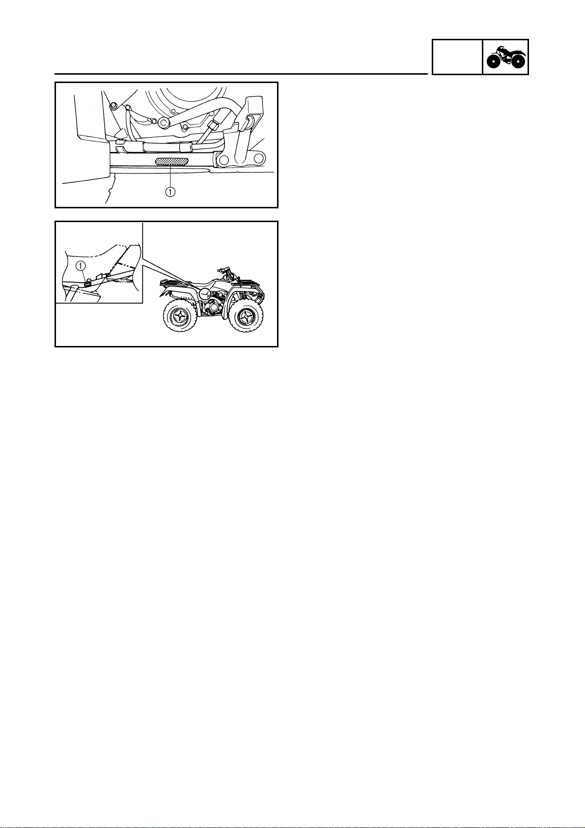
MACHINE IDENTIFICATION
GENERAL INFORMATION
MACHINE IDENTIFICATION
VEHICLE IDENTIFICATION NUMBER
The vehicle identification number
stamped into the left side of the frame.
MODEL LABEL
The model label
information will be needed to order spare
parts.
1
is affixed to the frame. This
INFO
1
is
– 1 –
Page 9
GENERAL SPECIFICATIONS
SPEC
SPECIFICATIONS
GENERAL SPECIFICATIONS
Model YFM40FP/YFM400FW
Model code: 4SHK (for CDN)
4SHL (for Europe)
4SHM (for Oceania)
Dimensions:
Overall length 1,956 mm (77.0 in)
Overall width 1,155 mm (45.5 in)
Overall height 1,144 mm (45.0 in)
Seat height 835 mm (32.9 in)
Wheelbase 1,210 mm (47.6 in)
Minimum ground clearance 215 mm (8.46 in)
Minimum turning radius 3,500 mm (137.8 in)
Basic weight:
With oil and full fuel tank 286 kg (631 lb)
Spark plug:
Type DR8EA
Manufacturer NGK
Spark plug gap 0.6 ~ 0.7 mm (0.024 ~ 0.028 in)
Transmission:
Primary reduction system Spur gear
Primary reduction ratio 76/24(3.167)
Secondary reduction system Shaft drive
Secondary reduction ratio 24/18 × 33/09 (4.889)
Transmission type Constant mesh 5-speed forward, 1-speed
reverse
Operation Left foot operation
Gear ratio 1st 38/13 (2.923)
2nd 34/18 (1.889)
3rd 30/22 (1.364)
4th 26/25 (1.040)
5th 24/29 (0.828)
Sub transmission low 20/24 × 27/15 (1.500)
high 20/24 × 22/20 (0.916)
Reverse gear 36/13 × 27/16 (4.673)
Chassis:
Frame type Steel tube frame
Caster angle 2.5˚
Trail 15 mm (0.59 in)
Tread (STD) front 850 mm (33.46 in)
Tread (STD) rear 820 mm (32.28 in)
Toe-in 5 ~ 15 mm (0.20 ~ 0.59 in)
– 2 –
Page 10

GENERAL SPECIFICATIONS
Model YFM40FP/YFM400FW
Tire:
Type Tubeless
Size front AT25 × 8-12
rear AT25 × 10-12
Manufacturer front DUNLOP (for CDN and Europe)
CHENG SHIN (for Oceania)
rear DUNLOP (for CDN and Europe)
CHENG SHIN (for Oceania)
Type front KT402 (for CDN and Europe)
C-828 (for Oceania)
rear KT406 (for CDN and Europe)
C-828 (for Oceania)
Tire pressure (cold tire):
Off-road riding
front 22 ~ 28 kPa (0.22 ~ 0.28 kg/cm
rear 22 ~ 28 kPa (0.22 ~ 0.28 kg/cm
Brake:
Front brake type Single disc brake
operation Right hand operation
Rear brake type Drum brake
operation Left hand and right foot operation
Electrical:
Ignition system C.D.I.
Generator system A.C. magneto
Battery type YTX20L-BS
Battery capacity 12 V 18 AH
Bulb wattage × quantity:
Headlight 12 V 30 W/30 W × 2
Taillight 12 V 7.5 W × 1
Meter light 12 V 3 W × 1
Neutral indicator light 12 V 1.7 W × 1
Reverse indicator light 12 V 1.7 W × 1
Oil temperature indicator light 12 V 1.7 W × 1
SPEC
2
, 3.2 ~ 4.0 psi)
2
, 3.2 ~ 4.0 psi)
– 3 –
Page 11
MAINTENANCE SPECIFICATIONS
SPEC
MAINTENANCE SPECIFICATIONS
ENGINE
Model YFM40FP/YFM400FW
Piston:
Piston to cylinder clearance 0.04 ~ 0.06 mm (0.0016 ~ 0.0024 in)
<Limit> <0.15 mm (0.0059 in)>
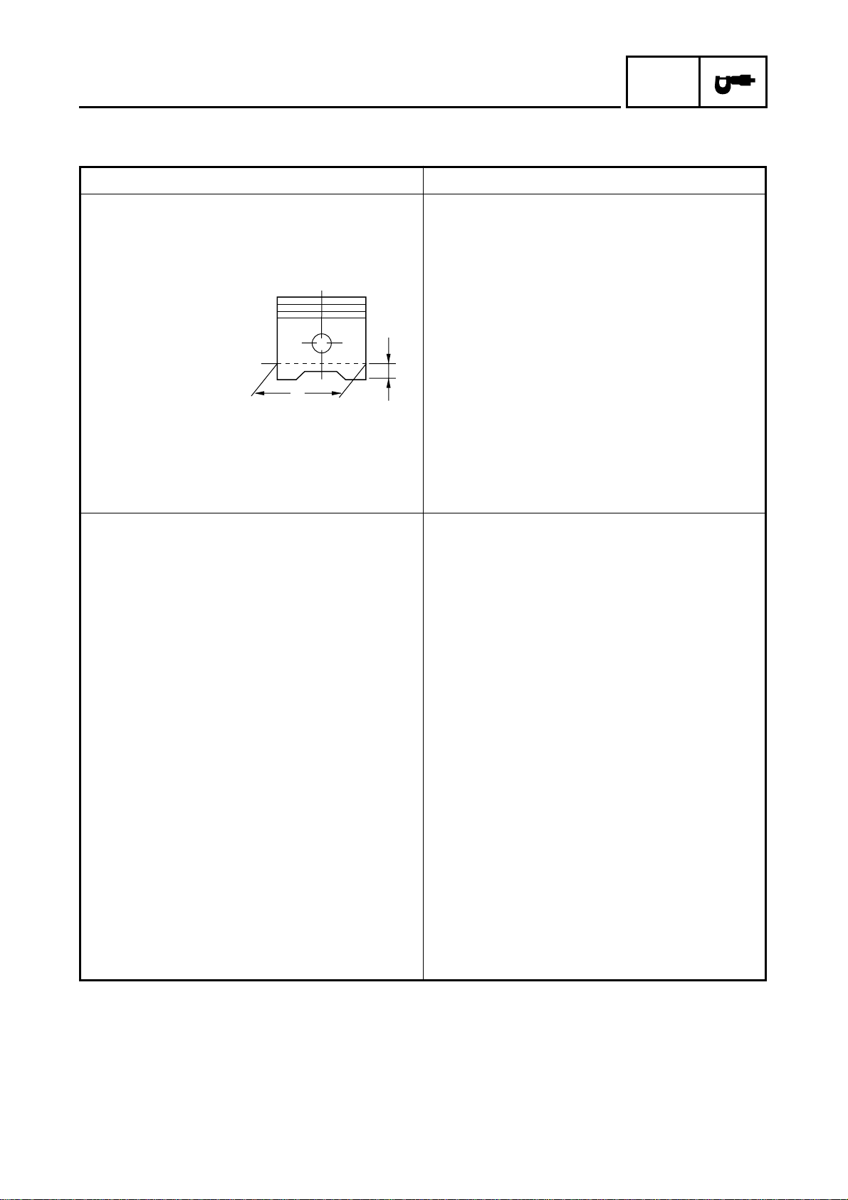
Piston size “D” 82.92 ~ 82.97 mm (3.265 ~ 3.267 in)
H
D
Measuring point “H” 5.5 mm (0.217 in)
Piston off-set 0.5 mm (0.02 in)
Piston off-set direction Intake side
Piston pin bore inside diameter 19.004 ~ 19.015 mm (0.7482 ~ 0.7486 in)
Piston pin outside diameter 18.990 ~ 18.995 mm (0.7476 ~ 0.7478 in)
Carburetor:
I. D. mark 4SHK 20 (for CDN)
4SHL 30 (for Europe and Oceania)
Main jet (M.J.) #105
Main air jet (M.A.J.) 0.7
Jet needle (J.N.) 5H26-2
Needle jet (N.J.) N-8 (#786)
Pilot air jet (P.A.J.1) 1.0
Pilot air jet (P.A.J.2) 0.9
Pilot outlet (P.O.) 0.75
Pilot jet (P.J.) #45
Pilot screw (P.S.) 2 turns out
Bypass 1 (B.P.1) 0.8
Bypass 2 (B.P.2) 0.8
Bypass 3 (B.P.3) 1.0
Valve seat size (V.S.) 2.5
Starter jet (G.S.1) #60
Throttle valve size (Th.V.) #130
Float height (F.H.) 11.4 ~ 13.4 mm (0.45 ~ 0.53 in)
Fuel level (F.L.) 1 ~ 2 mm (0.04 ~ 0.08 in)
Engine idle speed 1,350 ~ 1,450 r/min
Intake vacuum 33.3 kPa (250 mmHg, 10 inHg)
– 4 –
Page 12
MAINTENANCE SPECIFICATIONS
CHASSIS
Model YFM40FP/YFM400FW
Front suspension:
Shock absorber travel 67.5 mm (2.66 in)
Fork spring free length 229.5 mm (9.04 in)
Spring rate (K1) 19.6 N/mm (1.96 kg/mm, 111 lb/in)
Stroke (K1) 0 ~ 67.5 mm (0 ~ 2.66 in)
Optional spring No
Rear suspension:
Shock absorber travel 75 mm (2.95 in)
Spring free length 264.3 mm (10.4 in)
Fitting length 221.3 mm (8.71 in)
Spring rate (K1) 32.4 N/mm (3.24 kg/mm, 185 lb/in)
Stroke (K1) 0 ~ 75 mm (0 ~ 2.95 in)
Optional spring No
Front wheel:
Type Disc wheel
Rim size 12 × 6.0AT
Rim material Steel
Rim runout limit radial 2 mm (0.08 in)
lateral 2 mm (0.08 in)
Rear wheel:
Type Disc wheel
Rim size 12 × 7.5AT
Rim material Steel
Rim runout limit radial 2 mm (0.08 in)
lateral 2 mm (0.08 in)
Front disc brake:
Type Single
Disc outside diameter × thickness 180 × 3.5 mm (7.09 × 0.14 in)
Pad thickness 4.5 mm (0.18 in)
<Limit> <1.0 mm (0.04 in)>
Master cylinder inside diameter 15.87 mm (0.62 in)
Caliper cylinder inside diameter 32 mm (1.26 in)
Brake fluid type DOT 4
Brake lever & brake pedal:
Brake lever free play (left) 4 ~ 7 mm (0.16 ~ 0.28 in)
Brake pedal position 5 mm (0.2 in)
Brake pedal free play 20 ~ 30 mm (0.8 ~ 1.2 in)
Throttle lever free play 3 ~ 5 mm (0.1 ~ 0.2 in)
SPEC
– 5 –
Page 13

MAINTENANCE SPECIFICATIONS
Tightening torques
Tightening torque
Part to be tightened Thread size
Nm m·kg ft·lb
Steering shaft and frame M10 35 3.5 25
Tie-rod and locknut M10 30 3.0 22
Fuel tank and fuel cock M6 4 0.4 2.9
Front wheel and wheel hub M10 64 6.4 46
Front axle and wheel hub M16 150 15 110
Front brake caliper and steering knuckle M8 30 3.0 22
Front brake disc and wheel hub M8 30 3.0 22
Brake disc guard and steering knuckle M6 7 0.7 5.1
Front brake pipe nut M10 19 1.9 13
Master cylinder and handlebar M6 7 0.7 5.1
Footrest and frame M10 64 6.4 46
Front carrier and frame M8 31 3.1 22
Front carrier and front bumper M6 10 1.0 7.2
Front bumper and frame M8 31 3.1 22
Rear carrier and frame M8 33 3.3 24
SPEC
Remarks
ELECTRICAL
Model YFM40FP/YFM400FW
C.D.I.:
Magneto model/manufacturer F4T466/MITSUBISHI
Pickup coil resistance/color 459 ~ 561 Ω at 20 ˚C (68 ˚F)/White/Green –
White/Red
C.D.I. unit model/manufacturer F8T36471/MITSUBISHI
Ignition coil:
Model/manufacturer 2JN/YAMAHA
Minimum spark gap 6 mm (0.24 in)
Primary winding resistance 0.18 ~ 0.28 Ω at 20 ˚C (68 ˚F)
Secondary winding resistance 6.32 ~ 9.48 kΩ at 20 ˚C (68 ˚F)
Charging system:
Type A.C. magneto
Model/manufacturer F4T466/MITSUBISHI
Nominal output 14 V 15 A at 5,000 r/min
Charging coil resistance/color 0.70 ~ 0.86 Ω at 20 ˚C (68 ˚F)/White – White
Rectifier/regulator:
Model/manufacturer SH640E-11/SHINDENGEN
Capacity 14 A
Withstand voltage 200 V
– 6 –
Page 14
MAINTENANCE SPECIFICATIONS
Model YFM40FP/YFM400FW
Electric starter system:
Type Constant mesh type
Starter motor
Model/manufacturer DBEDU/DENSO
Output 0.7 kW
Armature coil resistance 0.011 ~ 0.013 Ω at 20 ˚C (68 ˚F)
Brush overall length 12 mm (0.47 in)
<Limit> <8.5 mm (0.33 in)>
Spring force 6.37 ~ 9.32 N (637 ~ 932 g, 22.5 ~ 32.9 oz)
Commutator diameter 28 mm (1.10 in)
<Wear limit> <27 mm (1.06 in)>
Mica undercut 0.6 mm (0.02 in)
Starter relay
Model/manufacturer MS5E-691/JIDECO
Amperage rating 180 A
Coil winding resistance 4.18 ~ 4.62 Ω at 20 ˚C (68 ˚F)
Fan motor relay:
Model/manufacturer 29U/MATSUSHITA
Coil winding resistance 72 ~ 88
Thermo unit:
Model/manufacturer 4SH/DENSO
Horn: (Europe and Oceania only)
Type Plane
Model/manufacturer MF-12/NIKKO
Circuit breaker:
Type Fuse
Amperage for individual circuit
Main fuse 30 A × 1
Headlight fuse 15 A × 1
Signaling system fuse 10 A × 1
Ignition fuse 10 A × 1
Auxiliary DC jack fuse 10 A × 1
Reserve fuse 30 A × 1
15 A × 1
10 A × 1
Ω
SPEC
– 7 –
Page 15
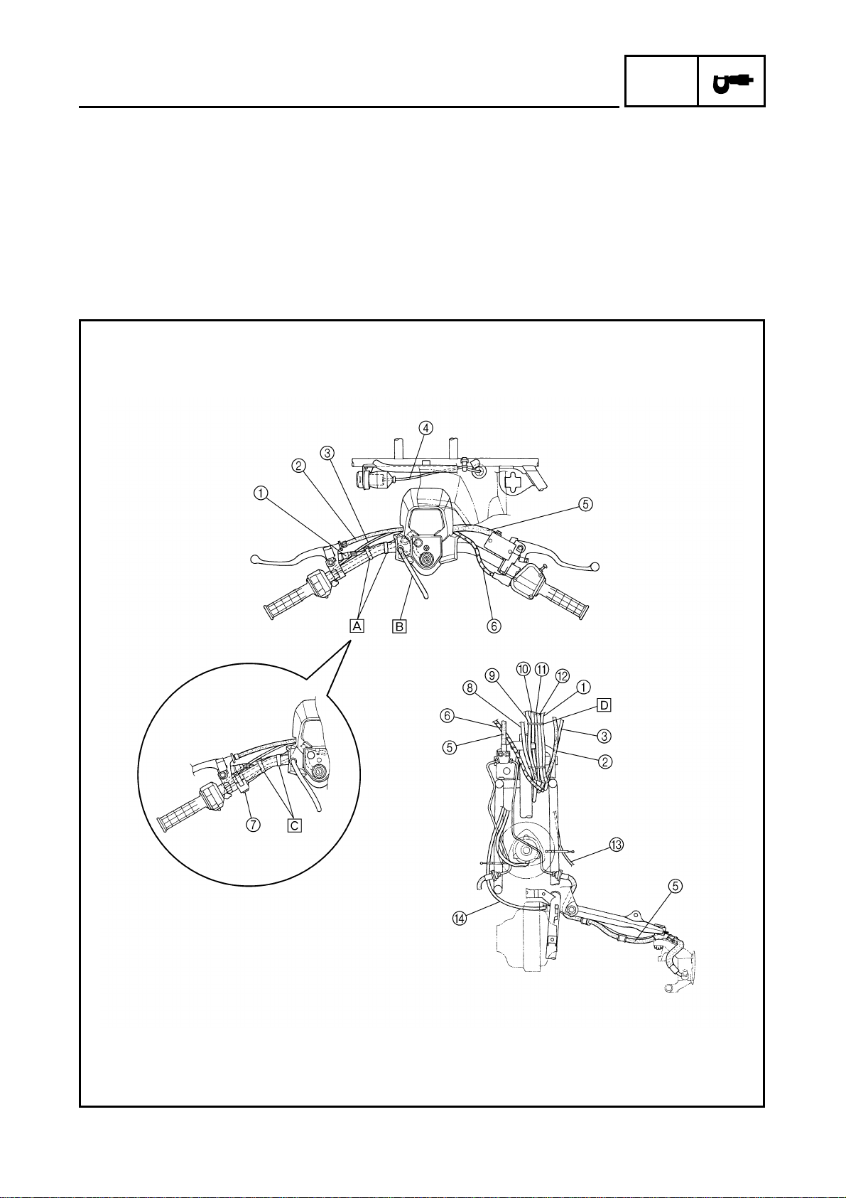
CABLE ROUTING
1
Rear brake switch
2
Rear brake cable
3
Starter cable
4
Auxiliary DC jack lead
5
Front brake hose
6
Throttle cable
7
Horn (for Europe and Oceania)
8
Speedometer cable
CABLE ROUTING
9
Speedometer lead
0
Main switch lead
A
Oil temperature indicator light lead
B
Handlebar switch lead
C
Reverse control cable 2
D Differential gear case breather hose
SPEC
– 8 –
Page 16

CABLE ROUTING
Å Fasten the handlebar switch lead and rear brake switch lead to the handlebar with the plastic band.
ı Route the fuel tank breather hose through the hole in the handlebar cover.
Ç Fasten the handlebar switch lead, rear brake switch lead and horn lead to the handlebar with the plastic
band. (for Europe and Oceania)
Î Fasten the speedometer lead, main switch lead, oil temperature indicator light lead, handlebar switch lead,
rear brake switch lead and horn lead with a plastic locking tie.
SPEC
– 9 –
Page 17

CABLE ROUTING
SPEC
1 Horn lead (for Europe and Oceania)
2 Taillight lead
3 Fuel tank breather hose
4 Starter cable
5 CDI unit
6 Positive battery lead
7 Negative battery lead
8 Carburetor overflow hose
9 Reverse switch lead
0 Starter motor lead
A CDI magneto lead
B Ground lead
C Oil hose
D Auxiliary DC jack
E Rear brake breather hose
6 Final gear case breather hose
7 Carburetor air vent hose
8 Reverse control cable 2
9 Throttle cable
– 10 –
Page 18
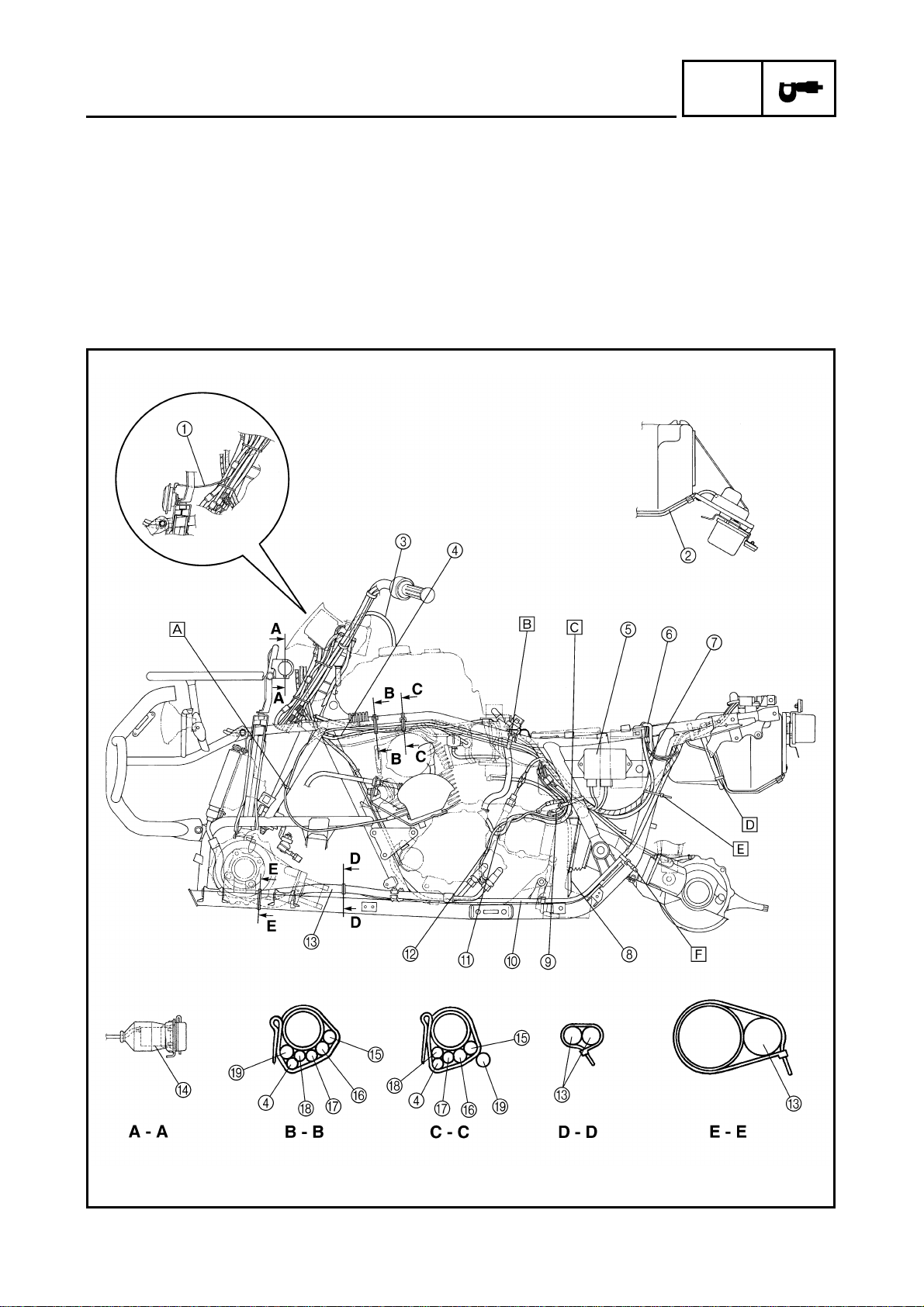
CABLE ROUTING
SPEC
Å Fasten the reverse control cable 2 to the frame
with the plastic clip.
ı Fasten the reverse control cable 2, rear brake
breather hose and final gear case breather hose
to the frame with the plastic band.
Ç Fasten the neutral switch lead, CDI magneto
lead, reverse switch lead and negative battery
lead to the frame with the plastic band.
Î Fasten the taillight lead to the frame with the
plastic band.
‰ Fasten the wire harness, negative battery lead
and starter motor lead to the frame with a plastic
locking tie.
Ï Fasten the starter motor lead to the frame with
the plastic band.
– 11 –
Page 19
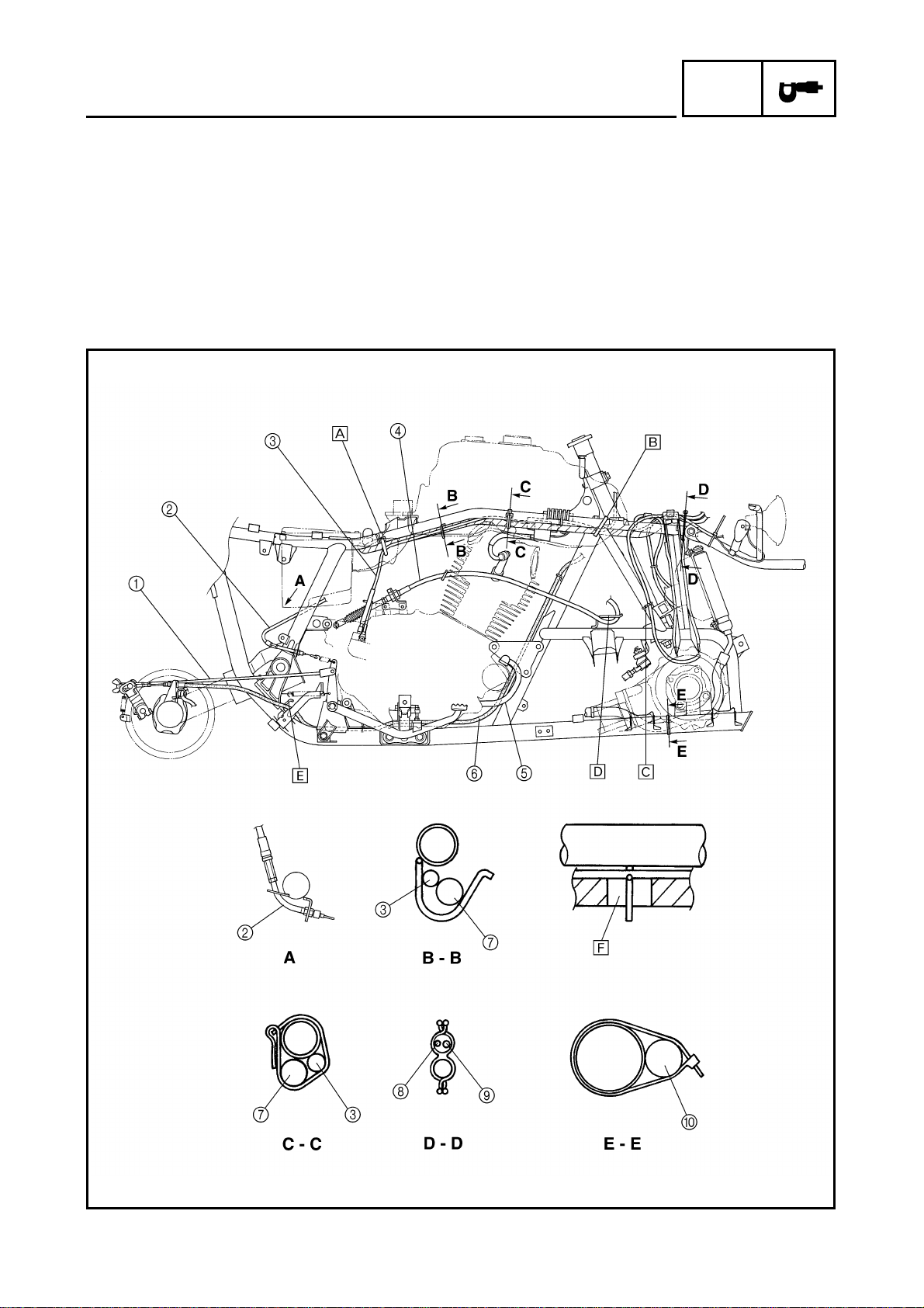
CABLE ROUTING
SPEC
1 Rear brake rod
2 Reverse control cable 2
3 Speedometer cable
4 Reverse control cable 1
5 Starter motor lead
6 Rear brake cable
7 Wire harness
8 Differential gear case breather
hose
9 Fan motor breather hose
0 Oil hose
Å Fasten the wire harness and speedometer cable to the frame
with the metal band.
ı Fasten the wire harness to the frame with the plastic band.
Ç Fasten the differential gear case breather hose to the frame
with the plastic clip.
Î Pass the reverse control cable 1 through the cable guide.
‰ Pass the rear brake cable through the cable guide.
Ï Align the portion of the wire harness marked with white tape
with the guide.
– 12 –
Page 20

CABLE ROUTING
SPEC
1 Fan motor breather hose
2 Differential gear case breather hose
3 Auxiliary DC jack lead
4 Reverse control cable 2
5 Battery
6 Main fuse
7 Positive battery lead
8 Neutral relay
9 Rectifier/regulator
0 Fan motor relay
A Starting circuit cut-off relay
B Starter relay
C Reverse relay
D Fan motor control unit
E Negative battery lead
F Fuse box
G Speedometer cable
H Starter motor lead
I Wire harness
J Taillight lead
K Fan motor control unit lead
L Neutral relay lead
– 13 –
Page 21

CABLE ROUTING
SPEC
M Starter relay lead
N Starting circuit cut-off relay lead
O Rectifier/regulator lead
P Reverse relay lead
Q Final gear case breather hose
R Rear brake breather hose
.
Å Fasten the wire harness to the frame with a plas-
tic locking tie.
ı Align the portion of the wire harness marked with
white tape with the guide.
– 14 –
Page 22

INTRODUCTION/
PERIODIC MAINTENANCE/LUBRICATION
INSP
ADJ
PERIODIC INSPECTIONS AND ADJUSTMENTS
INTRODUCTION
This chapter includes all information necessary to perform recommended inspections and adjustments. These preventive maintenance procedures, if followed, will ensure more reliable machine
operation and a longer service life. In addition, the need for costly overhaul work will be greatly
reduced. This information applies to machines already in service as well as new machines that are
being prepared for sale. All service technicians should be familiar with this entire chapter.
PERIODIC MAINTENANCE/LUBRICATION
ITEM ROUTINE
Valves*
Spark plug
Air filter
Carburetor*
Fuel line*
Engine oil
Transfer gear oil
Engine oil filter • Replace.
Engine oil strainer • Clean.
Final gear oil
Differential gear oil
Front brake*
Rear brake*
Clutch*
Drive select lever
safety system*
Wheels*
Wheel bearings*
Steering system*
• Check valve clearance.
• Adjust if necessary.
• Check condition.
• Adjust gap and clean.
• Replace if necessary.
• Clean.
• Replace if necessary.
• Check idle speed/starter operation.
• Adjust if necessary.
• Check fuel hose for cracks or damage.
• Replace if necessary.
• Replace (Warm engine before draining).
• Check oil level/oil leakage.
• Replace every 12 months.
• Check operation/fluid leakage/see NOTE.
• Correct if necessary.
• Check operation.
• Adjust if necessary.
• Check operation.
• Adjust if necessary.
• Check operation.
• Adjust if necessary.
• Check balance/damage/runout.
• Repair if necessary.
• Check bearing assemblies for looseness/
damage.
• Replace if damaged.
• Check operation.
• Replace if damaged.
• Check toe-in.
• Adjust if necessary.
INITIAL EVERY
1 month 3 months 6 months 6 months 1 year
Every 20 ~ 40 hours
(More often in wet or dusty areas.)
– 15 –
Page 23

PERIODIC MAINTENANCE/LUBRICATION
INSP
ADJ
ITEM ROUTINE
Front axle boots*
Fittings and Fas-
teners*
*It is recommended that these items be serviced by a Yamaha dealer.
• Check operation.
• Replace if damaged.
• Check all chassis fittings and fasteners.
• Correct if necessary.
1 month 3 months 6 months 6 months 1 year
INITIAL EVERY
NOTE:
● Recommended brake fluid: DOT 4 (If DOT 4 is not available, DOT 3 can be used.)
● Brake fluid replacement:
1.When disassembling the master cylinder or caliper cylinder, replace the brake fluid. Normally
check the brake fluid level and add fluid as required.
2.On the inner parts of the master cylinder and caliper cylinder, replace the oil seals every two
years.
3.Replace the brake hoses every four years, or if cracked or damaged.
WARNING
Indicates a potential hazard that could result in serious injury or death.
– 16 –
Page 24

SEAT, CARRIERS, FENDERS AND FUEL TANK
SEAT, CARRIERS, FENDERS AND
FUEL TANK
REMOVAL
1.Place the machine on a level place.
2.Remove:
● Seat
NOTE:
Pull up the seat lock lever 1, then remove by
pulling up on the rear of the seat.
3.Disconnect:
● Auxiliary DC jack coupler 1
● Headlight couplers 2
4.Remove:
● Plastic locking tie 3
INSP
ADJ
5.Remove:
● Front carrier 1
(with the auxiliary DC jack 2)
6.Remove:
● Front bumper 1
– 17 –
Page 25

SEAT, CARRIERS, FENDERS AND FUEL TANK
7.Remove:
● Front fender 1
INSP
ADJ
8.Turn the fuel cock lever to “OFF”.
9.Disconnect:
● Fuel hose 1
NOTE:
Place a rag on the engine to absorb spilled
fuel.
WARNING
Gasoline is highly flammable.
Avoid spilling fuel on the hot engine.
10.Remove:
● Fuel tank 1
NOTE:
Remove the air duct 2 from fuel tank.
– 18 –
Page 26

SEAT, CARRIERS, FENDERS AND FUEL TANK
11.Remove:
● Main fuse 1
(from the battery holding bracket)
● Battery holding bracket 2
12.Disconnect:
● Battery leads
CAUTION:
Disconnect the negative lead first and then
disconnect the positive lead.
13.Remove:
● Battery 3
14.Remove:
● Rear carrier 1
INSP
ADJ
15.Remove:
● Rear fender 1
– 19 –
Page 27

SEAT, CARRIERS, FENDERS AND FUEL TANK
INSTALLATION
Reverse the “REMOVAL” procedure.
Note the following points.
1.Install:
● Fuel tank 1
NOTE:
● Insert the fuel tank air duct into the fuel tank
hole a. Refer to “CABLE ROUTING”.
● Insert the fuel tank breather hose 2 into the
handlebar protector hole b. Refer to
“CABLE ROUTING”.
INSP
ADJ
2.Install:
● Rear fender
● Battery 1
● Battery holding bracket 2
● Main fuse 3
3.Connect:
● Battery leads
CAUTION:
Connect the positive lead first and then
connect the negative lead.
NOTE:
Pass the positive lead through the lead holders
4. Refer to “CABLE ROUTING”.
4.Install:
● Rear carrier 1
– 20 –
Bolt (rear carrier and frame):
T
33 Nm (3.3 m • kg, 24 ft • lb)
.
R
.
Bolt (rear carrier and rear
bumper):
9 Nm (0.9 m • kg, 6.5 ft • lb)
Page 28

SEAT, CARRIERS, FENDERS AND FUEL TANK
5.Install:
● Front fender
● Front bumper 1
Bolt (front bumper):
T
31 Nm (3.1 m • kg, 22 ft • lb)
.
R
.
6.Install:
● Front carrier 1
(with the auxiliary DC jack 2)
Bolt (front carrier and frame):
T
31 Nm (3.1 m • kg, 22 ft • lb)
.
R
.
Nut (front carrier and front
bumper):
10 Nm (1.0 m • kg, 7.2 ft • lb)
INSP
ADJ
7.Install:
● Plastic locking tie 1
8.Connect:
● Headlight couplers 2
● Auxiliary DC jack coupler 3
9.Install:
● Seat
NOTE:
Insert the lobes 1 on the seat front into the
receptacles 2 on the frame, then push down
the seat at the rear.
– 21 –
Page 29

STARTER LEVER FREE PLAY ADJUSTMENT
ENGINE
STARTER LEVER FREE PLAY
ADJUSTMENT
1.Check:
● Starter lever free play a
Out of specification → Adjust.
Starter lever free play:
5.5 ~ 14.2 mm (0.22 ~ 0.56 in)
2.Adjust:
● Starter lever free play
*********************************************
Adjustment steps:
●Pull back the adjuster cover 1.
●Loosen the locknut 2.
●Turn the adjuster 3 in or out until the correct
free play is obtained.
INSP
ADJ
Turning in Free play is increased.
Turning out Free play is decreased.
●Tighten the locknut 2.
●Push in the adjuster cover 1.
WARNING
After adjusting the free play, turn the handlebar to right and left, and make sure that
the engine idling speed does not increase.
*********************************************
– 22 –
Page 30

FRONT BRAKE PAD INSPECTION/
AIR BLEEDING (HYDRAULIC BRAKE SYSTEM)
CHASSIS
FRONT BRAKE PAD INSPECTION
1.Remove:
● Front wheels
2.Inspect:
● Brake pad
Wear indicators 1 almost touch the brake
disc → Replace the brake pads as a set.
Refer to “FRONT BRAKE”.
3.Operate the brake lever.
4.Install:
● Front wheels
INSP
ADJ
AIR BLEEDING (HYDRAULIC BRAKE
SYSTEM)
WARNING
Bleed the brake system if:
● The system has been disassembled.
● A brake hose or brake pipe have been
loosened or removed.
● The brake fluid has been very low.
● The brake operation has been faulty.
A loss of braking performance may occur if
the brake system is not properly bled.
1.Bleed:
● Brake system
*********************************************
Air bleeding steps:
a. Add the proper brake fluid to the reservoir.
b. Install the diaphragm. Be careful not to spill
any fluid or allow the reservoir to overflow.
c. Connect the clear plastic hose 1 tightly to
the caliper bleed screw 2.
d. Place the other end of the hose into a con-
tainer.
e. Slowly apply the brake lever several times.
f. Pull the lever in and hold it.
– 23 –
Page 31

AIR BLEEDING (HYDRAULIC BRAKE SYSTEM)/
REAR SHOCK ABSORBER ADJUSTMENT
g. Loosen the bleed screw and allow the lever
to travel towards its limit.
h. Tighten the bleed screw when the lever limit
has been reached, then release the lever.
i. Repeat steps (e) to (h) until all the air bub-
bles have disappeared from the fluid.
j. Tighten the bleed screw.
Bleed screw:
T
6 Nm (0.6 m • kg, 4.3 ft • lb)
.
R
.
NOTE:
If bleeding is difficult, it may be necessary to
let the brake fluid settle for a few hours.
Repeat the bleeding procedure when the tiny
bubbles in the system have disappeared.
k. Add brake fluid to the proper level.
Refer to “BRAKE FLUID LEVEL INSPEC-
TION”.
INSP
ADJ
WARNING
Check the operation of the brake after
bleeding the brake system.
*********************************************
REAR SHOCK ABSORBER ADJUSTMENT
1.Adjust:
● Spring preload
Turn the adjuster to increase or decrease the
spring preload.
NOTE:
The spring preload of the rear shock absorber
can be adjusted to suit the rider’s preference,
weight, and the riding conditions.
– 24 –
Standard position: B
Softest position: A
Stiffest position: E
Page 32

INSP
TIRE INSPECTION
TIRE INSPECTION
WARNING
This model is equipped with low pressure
tires. It is important that they be inflated
correctly and maintained at the proper
pressures.
● TIRE CHARACTERISTICS
1)Tire characteristics influence the han-
dling of ATV’s. The tires listed below
have been approved by Yamaha Motor
Co., Ltd. for this model. If other tire combinations are used, they can adversely
affect your machine’s handling characteristics and are therefore not recommended.
For CDN and Europe
Manufacturer Size Type
ADJ
Front DUNLOP AT25 × 8-12 KT402
Rear DUNLOP AT25 × 10-12 KT406
For Oceania
Manufacturer Size Type
Front CHENG SHIN AT25 × 8-12 C-828
Rear CHENG SHIN AT25 × 10-12 C-828
● TIRE PRESSURE
1)Recommended tire pressure
Front 25 kPa (0.25 kg/cm
Rear 25 kPa (0.25 kg/cm
2
, 3.6 psi)
2
, 3.6 psi)
2)Tire pressure below the minimum speci-
fied could cause the tire to dislodge from
the rim under severe riding conditions.
The following are minimums:
Front 22 kPa (0.22 kg/cm
Rear 22 kPa (0.22 kg/cm
2
, 3.2 psi)
2
, 3.2 psi)
3)Use no more than
Front 250 kPa (2.5 kg/cm
Rear 250 kPa (2.5 kg/cm
2
, 36 psi)
2
, 36 psi)
when seating the tire beads. Higher pres-
sures may cause the tire to burst.
Inflate the tires very slowly and carefully.
Fast inflation could cause the tire to
burst.
● MAXIMUM LOADING LIMIT
1)Vehicle load limits: 220 kg (485 lb)*
* Total weight of cargo, trailer hitch verti-
cal load, rider, and accessories.
2)Storage box: 2 kg (4.4 lb)
– 25 –
Page 33

INSP
TIRE INSPECTION
3)Trailer hitch:
Horizontal load:
500 kg (1,102 lb) (for CDN)
410 kg (904 lb) (for Europe and Oceania)
Total weight of trailer and cargo.
Vertical load: 15 kg (33 lb)
Vertical weight on trailer hitch joint.
Be extra careful of the machine balance
and stability when towing a trailer.
1.Measure:
● Tire pressure (cold tire pressure)
Out of specification → Adjust.
NOTE:
● The low-pressure tire gauge 1 is included in
the standard equipment.
● If dust or the like is stuck to this gauge, it does
not provide correct readings. Therefore, make
two measurements on the tire pressure and
get the second reading.
ADJ
Cold tire
pressure
Standard
Minimum
Maximum
Front Rear
25 kPa
(0.25 kg/cm
3.6 psi)
22 kPa
(0.22 kg/cm
3.2 psi)
28 kPa
(0.28 kg/cm
4.0 psi)
2
,
2
,
2
,
25 kPa
(0.25 kg/cm2,
3.6 psi)
22 kPa
(0.22 kg/cm2,
3.2 psi)
28 kPa
(0.28 kg/cm2,
4.0 psi)
WARNING
Uneven or improper tire pressure may
adversely affect the handling of this
machine and may cause loss of control.
● Maintain proper tire pressures.
● Set tire pressures when the tires are cold.
● Tire pressures must be equal in both
front tires and equal in both rear tires.
2.Inspect:
● Tire surfaces
Wear/damage → Replace.
Tire wear limit a:
Front and rear: 3.0 mm (0.12 in)
WARNING
It is dangerous to ride with a worn-out tire.
When tire wear is out of specification,
replace the tire immediately.
– 26 –
Page 34

BATTERY INSPECTION
EB305000
ELECTRICAL
BATTERY INSPECTION
NOTE:
Since the MF battery is a sealed type battery, it
is not possible to measure the specific gravity
of the electrolyte in order to check the charge
state of the battery. Therefore the charge of
the battery has to be checked by measuring
the voltage at the battery terminals.
CAUTION:
CHARGING METHOD
● This is a sealed type battery. Never
remove the sealing caps. If the sealing
caps have been removed, the balance will
not be maintained and battery performance will deteriorate.
● Charging time, charging current and
charging voltage for the MF battery are
different from those of general type batteries. The MF battery should be charged
as explained in “CHARGING METHOD”. If
the battery is overcharged, the electrolyte
level will drop considerably. Therefore,
take special care when charging the battery.
INSP
ADJ
WARNING
Battery electrolyte is dangerous; it contains sulfuric acid which is poisonous and
highly caustic.
Always follow these preventive measures:
● Avoid bodily contact with electrolyte as it
can cause severe burns or permanent eye
injury.
● Wear protective eye gear when handling
or working near batteries.
Antidote (EXTERNAL):
● SKIN - Wash with water.
● EYES - Flush with water for 15 minutes
and get immediate medical attention.
Antidote (INTERNAL):
● Drink large quantities of water or milk fol-
lowed with milk of magnesia, beaten egg
or vegetable oil. Get immediate medical
attention.
– 27 –
Page 35

BATTERY INSPECTION
Batteries generate explosive hydrogen gas.
Always follow these preventive measures:
● Charge batteries in a well-ventilated area.
● Keep batteries away from fire, sparks or
open flames (e.g., welding equipment,
lighted cigarettes, etc.)
● DO NOT SMOKE when charging or han-
dling batteries.
KEEP BATTERIES AND ELECTROLYTE
OUT OF REACH OF CHILDREN.
1.Remove:
● Seat
Refer to “SEAT, CARRIERS, FENDERS
AND FUEL TANK”.
INSP
ADJ
2.Disconnect:
● Battery leads
CAUTION:
First disconnect the negative lead 1, then
disconnect the positive lead 2.
3.Remove:
● Main fuse 3
(from the battery holding bracket)
● Battery holding bracket
● Battery
4.Check:
● Battery condition
*********************************************
Battery condition checking steps:
●Connect a digital voltmeter to the battery ter-
minals.
Tester (+) lead → battery (+) terminal
Tester (–) lead → battery (–) terminal
– 28 –
Page 36

BATTERY INSPECTION
NOTE:
The charge state of an MF battery can be
checked by measuring the open-circuit voltage
(i.e. the voltage when the positive terminal is
disconnected).
INSP
ADJ
Open-circuit
voltage
12.8 V or higher
●Check the condition of the battery using the
Charging time
No charging is
necessary.
following charts.
Example:
●Open-circuit voltage = 12.0 V
●Charging time = 6.5 hours
●Charge condition of the battery = 20 ~ 30%
●Charging method for MF batteries
CAUTION:
● If it is impossible to set the standard
charging current, be careful not to overcharge.
● When charging the battery, be sure to
remove it from the motorcycle. (If charg-
ing has to be done with the battery
mounted on the motorcycle, be sure to
disconnect the wire at the negative termi-
nal.)
● Never remove the sealing caps of an MF
battery.
● Make sure that the charging clips are in
full contact with the terminal and that
they are not shorted together. (A cor-
roded clip on the charger may cause the
battery to generate heat in the contact
area. A weak clip spring may cause
sparks.)
● Before removing the clips from the bat-
tery terminals, be sure to turn off the
charger’s power switch.
● The open-circuit voltage variation for the
MF battery, after charging, is shown
below. As shown in the figure, the open-
circuit voltage stabilizes about 30 min-
utes after charging has been completed.
Therefore, wait 30 minutes after charging
is completed before measuring the open-
circuit voltage.
– 29 –
Page 37

BATTERY INSPECTION
Charging method using a variable voltage charger
INSP
ADJ
– 30 –
Page 38

BATTERY INSPECTION
Charging method using a constant voltage charger
INSP
ADJ
– 31 –
Page 39

BATTERY INSPECTION/
FUSE INSPECTION
5.Inspect:
● Battery terminals
Dirty → Clean with a wire brush.
Poor connection → Correct.
NOTE:
After cleaning the terminals, apply a light coat
of grease.
6.Install:
● Battery
● Battery holding bracket
● Main fuse
7.Connect:
● Battery leads
CAUTION:
First, connect the positive lead 1, then
connect the negative lead 2.
INSP
ADJ
NOTE:
Connect the positive lead pass the lead holders 3. Refer to “CABLE ROUTING”.
8.Install:
● Seat
Refer to “SEAT, CARRIERS, FENDERS
AND FUEL TANK”.
FUSE INSPECTION
CAUTION:
Always turn off the main switch when
checking or replacing a fuse. Otherwise, a
short circuit may occur.
1.Remove:
● Seat
Refer to “SEAT, CARRIERS, FENDERS
AND FUEL TANK”.
2.Inspect:
● Fuses
*********************************************
Inspection steps:
●Connect the pocket tester to the fuse and
check it for continuity.
– 32 –
Page 40

INSP
FUSE INSPECTION
NOTE:
Set the tester to the “Ω × 1” position.
Pocket tester:
P/N. YU-03112, 90890-03112
● If the tester indicates “0”, replace the fuse.
*********************************************
3.Replace:
● Blown fuse
*********************************************
Replacement steps:
●Turn off the ignition.
●Install a new fuse of the proper amperage.
●Turn on switches to verify operation of the
related electrical devices.
●If the fuse immediately blows again, check
the electrical circuit.
ADJ
*********************************************
Description Current rating Quantity
Main 30 A 1
Headlight 15 A 1
Ignition 10 A 1
Terminal
(Auxiliary
10 A 1
DC jack)
Signal 10 A 1
Reserve 30 A 1
Reserve 15 A 1
Reserve 10 A 1
WARNING
Never use a fuse with a rating other than
that specified. Never use other materials in
place of a fuse. An improper fuse may
cause extensive damage to the electrical
system, a malfunction of the lighting and
ignition systems and could possibly cause
a fire.
– 33 –
4.Install:
● Seat
Refer to “SEAT, CARRIERS, FENDERS
AND FUEL TANK”.
Page 41

ENGINE ASSEMBLY AND ADJUSTMENT
ENGINE OVERHAUL
ENGINE ASSEMBLY AND ADJUSTMENT
VALVE, CAMSHAFT AND ROCKER ARM
1 Locknut (valve adjusting)
2 Adjuster (valve adjusting)
3 Wave washer
4 Rocker arm
5 Rocker arm shaft
6 O-ring
7 Valve cotter
8 Valve spring retainer
9 Oil seal
0 Valve spring
A Valve spring seat
B Valve
C Bearing retainer
D Lock washer
ENG
E Bearing
F Camshaft
G Bearing
H Circlip
I Valve guide
VALVE CLEARANCE (COLD):
Intake: 0.06 ~ 0.10 mm (0.002 ~ 0.004 in)
A
Exhaust: 0.16 ~ 0.20 mm
(0.006 ~ 0.008 in)
VALVE SPRING TILT LIMIT:
Inner spring:
B
2.5˚ or 1.6 mm (0.06 in)
Outer spring:
2.5˚ or 1.6 mm (0.06 in)
VALVE SPRING LENGTH LIMIT (FREE):
C
Inner spring: 37.9 mm (1.49 in)
Outer spring: 41.27 mm (1.62 in)
STEM RUNOUT LIMIT:
D
0.02 mm (0.0008 in)
VALVE SEAT WIDTH LIMIT:
E
1.6 mm (0.06 in)
FWD
– 34 –
Page 42

FRONT AND REAR WHEELS
CHASSIS
FRONT AND REAR WHEELS
1 Wheel cap
2 Cotter pin
3 Axle nut
4 Plain washer
5 Wheel nut
6 Front wheel
7 Front wheel hub
‰ Tapered wheel nuts are used for both the front
and rear wheels. Install the nut with its tapered
side towards the wheel.
8 O-ring
9 Rear wheel
0 Rear brake drum
A Rear wheel hub
CHAS
TIRE AIR PRESSURE
Cold Tire Pressure Front Rear
Standard
Minimum
Maximum
A
B
25 kPa
(0.25 kg/cm2,
3.6 psi)
22 kPa
(0.22 kg/cm2,
3.2 psi)
28 kPa
(0.28 kg/cm2,
4.0 psi)
TIRE SIZE:
FRONT: AT25 × 8-12
REAR: AT25 × 10-12
RIM SIZE:
FRONT: 12 × 6.0AT
REAR: 12 × 7.5AT
25 kPa
(0.25 kg/cm2,
3.6 psi)
22 kPa
(0.22 kg/cm2,
3.2 psi)
28 kPa
(0.28 kg/cm2,
4.0 psi)
WHEEL RUNOUT LIMIT:
C
RADIAL: 2 mm (0.08 in)
LATERAL: 2 mm (0.08 in)
D TIRE WEAR LIMIT: 3 mm (0.12 in)
FWD
– 35 –
Page 43

FRONT AND REAR WHEELS
REMOVAL
Front wheels
1.Place the machine on a level surface.
2.Loosen:
● Nuts (front wheel)
Apply the front brake.
3.Block the rear wheels, and elevate the front
wheels by placing the suitable stand under
the frame.
4.Remove:
● Nuts (front wheel)
● Front wheel
CHAS
5.Remove:
● Wheel cap
● Cotter pin 1
● Nut (wheel hub) 2
● Washer 3
6.Remove:
● Front brake caliper 1
OTE:
Do not depress the brake lever when the
wheel is off the machine otherwise the brake
pads will be forced shut.
7.Remove:
● Front wheel hub 1
(with brake disc)
– 36 –
Page 44

FRONT AND REAR WHEELS
8.Remove:
● Front brake disc 1
CHAS
– 37 –
Page 45

FRONT BRAKE
1 Brake master cylinder reservoir cap
2 Brake master cylinder reservoir dia-
phragm
3 Brake master cylinder
4 Brake master cylinder kit
5 Copper washer
6 Union bolt
7 Brake hose
8 Brake pipe
9 Brake disc
BRAKE FLUID TYPE:
A
DOT 4
BRAKE PAD WEAR LIMIT:
B
1.0 mm (0.04 in)
BRAKE DISC WEAR LIMIT:
C
3.0 mm (0.12 in)
FRONT BRAKE
0 Bleed screw
A Retaining bolt
B Brake caliper
C Pad shim
D Brake pad
E Piston
F Piston seal
G Brake disc guard
CHAS
FWD
– 38 –
Page 46

FRONT BRAKE
CHAS
CAUTION:
Disc brake components rarely require disassembly. DO NOT:
● Disassemble components unless abso-
lutely necessary.
● Use solvents on internal brake components.
● Use contaminated brake fluid for clean-
ing. Use only clean brake fluid.
● Allow brake fluid to come in contact with
the eyes, otherwise eye injury may occur.
● Allow brake fluid to contact painted sur-
faces or plastic parts otherwise damage
may occur.
● Disconnect any hydraulic connection oth-
erwise the entire system must be disassembled, drained, cleaned, and then
properly filled and bled after reassembly.
BRAKE PAD REPLACEMENT
OTE:
It is not necessary to disassemble the brake
caliper and brake hose to replace the brake
pads.
1.Remove:
● Front wheel
2.Loosen:
● Retaining bolts 1
3.Remove:
● Front brake caliper 2
4.Remove:
● Retaining bolts 1
– 39 –
Page 47

FRONT BRAKE
CHAS
5.Remove:
● Brake pads 1
(with pad shim 2)
● Pad spring 3
OTE:
● When pad replacement is required, also
replace the pad spring and shim.
● Replace the pads as a set if either is found to
be worn to the wear limit a.
Wear limit a:
1.0 mm (0.04 in)
6.Install:
● Pad shim
(onto inside brake pad)
● Pad spring
● Brake pads
*********************************************
Installation steps:
●Connect a suitable hose 1 tightly to the cali-
per bleed screw 2. Then, place the other
end of this hose into an open container.
●Loosen the caliper bleed screw and push the
pistons into the caliper with the finger.
●Tighten the caliper bleed screw 2.
Caliper bleed screw:
6 Nm (0.6 m • kg, 4.3 ft • lb)
T
.
R
.
●Install the pad shim 3 (new) onto the brake
pad (new).
OTE:
The arrow mark a on the pad shim must point
in the direction of the disc rotation.
●Install the pad spring (new) and brake pads
(new).
*********************************************
– 40 –
Page 48

FRONT BRAKE
CHAS
7.Install:
● Retaining bolts
● Front brake caliper
Retaining bolt:
18 Nm (1.8 m • kg, 13 ft • lb)
T
.
R
.
Bolt (front brake caliper):
30 Nm (3.0 m • kg, 22 ft • lb)
8.Install:
● Front wheel
9.Inspect:
● Brake fluid level
Refer to “FRONT BRAKE FLUID LEVEL
INSPECTION”.
a “LOWER” level line
10.Check:
● Brake lever operation
A soft or spongy feeling → Bleed brake system.
Refer to “AIR BLEEDING (HYDRAULIC
BRAKE SYSTEM)”.
CALIPER DISASSEMBLY
OTE:
Before disassembling the front brake caliper,
drain the brake hose, master cylinder, brake
caliper and reservoir tank of their brake fluid.
1.Remove:
● Front wheel
2.Loosen:
● Union bolt
● Retaining bolts
● Retaining bolt (caliper bracket)
3.Remove:
● Front brake caliper
● Retaining bolts
● Brake pads
(with pad shim)
● Pad spring
Refer to “BRAKE PAD REPLACEMENT”.
– 41 –
Page 49

FRONT BRAKE
CHAS
4.Remove:
● Union bolt 1
● Copper washers 2
● Brake hose 3
OTE:
Place the open end of the hose into a container and pump the oil fluid out carefully.
5.Remove:
● Caliper body 1
● Caliper bracket 2
OTE:
Before removing the caliper body from the
bracket, disconnect the dust boot from the
guide shaft on the bracket.
6.Remove:
● Piston
● Piston seals 1
*********************************************
Removal steps:
●Blow compressed air into the hose joint
opening to force out the caliper piston from
the caliper body.
●Remove the piston seals.
WARNING
Never try to pry out the piston.
*********************************************
MASTER CYLINDER DISASSEMBLY
OTE:
Before disassembling the front brake master
cylinder, drain the brake hose, master cylinder,
brake caliper and reservoir tank of their brake
fluid.
– 42 –
Page 50

FRONT BRAKE
CHAS
1.Remove:
● Brake lever 1
● Spring
● Union bolt 2
● Copper washers 3
● Brake hose 4
OTE:
Hold a container under the master cylinder and
under the hose end to collect any remaining
brake fluid.
2.Remove:
● Brake master cylinder reservoir cap 1
● Brake master cylinder reservoir diaphragm
holder
● Brake master cylinder reservoir diaphragm
● Brake master cylinder 2
3.Remove:
● Dust boot 1
● Circlip 2
● Brake master cylinder kit 3
Drain the excess fluid.
INSPECTION AND REPAIR
Recommended brake component
replacement schedule:
Brake pads As required
Piston seal Every two years
Brake hoses Every four years
Brake fluid Replace only when
brakes are disassembled.
WARNING
All internal parts should be cleaned in new
brake fluid only. Do not use solvents as
they will cause seals to swell and distort.
– 43 –
Page 51

FRONT BRAKE
CHAS
1.Inspect:
● Caliper piston 1
Scratches/rust/wear → Replace caliper
assembly.
● Caliper cylinder 2
Wear/scratches → Replace caliper assembly.
● Caliper body 3
Cracks/damage → Replace.
● Oil delivery passage (caliper body)
Blow out with compressed air.
WARNING
Replace the piston seal whenever the caliper is disassembled.
2.Inspect:
● Brake master cylinder
Wear/scratches → Replace the brake master
cylinder assembly.
● Brake master cylinder body
Cracks/damage → Replace.
● Oil delivery passage (master cylinder body)
Blow out with compressed air.
3.Inspect:
● Brake master cylinder kit
Scratches/wear/damage → Replace as a
set.
4.Inspect:
● Brake master cylinder reservoir diaphragm
Wear/damage → Replace.
5.Inspect:
● Brake hose
Cracks/wear/damage → Replace.
– 44 –
Page 52

FRONT BRAKE
CHAS
6.Measure:
● Brake pads (thickness) a
Out of specification → Replace.
OTE:
● When pad replacement is required, also
replace the pad spring and shim.
● Replace the pads as a set if either is found to
be worn to the wear limit a.
Wear limit a:
1.0 mm (0.04 in)
7.Inspect:
● Brake disc
Galling/damage → Replace.
8.Measure:
● Brake disc deflection
Out of specification → Inspect wheel runout.
If wheel runout is in good condition, replace
the brake disc(s).
Maximum deflection:
0.15 mm (0.006 in)
● Brake disc thickness a
Out of specification → Replace.
– 45 –
Minimum thickness:
3.0 mm (0.12 in)
1 Dial gauge
Page 53

FRONT BRAKE
CHAS
OTE:
Tighten the bolts (brake disc) in stage using a
crisscross pattern.
Bolt (brake disc):
30 Nm (3.0 m • kg, 22 ft • lb)
T
.
R
.
CALIPER ASSEMBLY
WARNING
● All internal parts should be cleaned in
new brake fluid only.
● Internal parts should be lubricated with
brake fluid when installed.
Recommended brake fluid:
DOT 4
● Replace the piston seals whenever a cali-
per is disassembled.
1.Install:
● Piston seals 1
● Piston 2
New
WARNING
Always use new piston seals.
2.Install:
● Caliper bracket 1
● Caliper body 2
OTE:
Apply lithium soap base grease onto the caliper guide shaft and retaining bolt.
– 46 –
Page 54

FRONT BRAKE
CHAS
3.Install:
● Brake caliper 1
(temporarily)
● Copper washers 2
● Brake hose 3
● Union bolt 4
New
Union bolt:
27 Nm (2.7 m • kg, 19 ft • lb)
T
.
R
.
CAUTION:
When installing the brake hose on the caliper, make sure that the brake pipe touches
the projection a on the brake caliper.
WARNING
● Proper hose routing is essential to insure
safe machine operation. Refer to “CABLE
ROUTING”.
● Always use new copper washers.
4.Remove:
● Brake caliper
5.Install:
● Pad spring
● Brake pads
(with pad shim)
● Retaining bolts
● Front brake caliper
Refer to “BRAKE PAD REPLACEMENT”.
T
.
R
.
– 47 –
Retaining bolt (caliper bracket):
28 Nm (2.8 m • kg, 20 ft • lb)
Retaining bolt:
18 Nm (1.8 m • kg, 13 ft • lb)
Bolt (front brake caliper):
30 Nm (3.0 m • kg, 22 ft • lb)
Page 55

FRONT BRAKE
CHAS
6.Fill:
● Reservoir tank
Recommended brake fluid:
DOT 4
OTE:
If DOT 4 is not available, 3 can be used.
CAUTION:
Brake fluid may erode painted surfaces or
plastic parts. Always clean up spilled fluid
immediately.
WARNING
● Use only the designated quality brake
fluid: otherwise, the rubber seals may
deteriorate, causing leakage and poor
brake performance.
● Refill with the same type of brake fluid:
mixing fluids may result in a harmful
chemical reaction and lead to poor performance.
● Be careful that water does not enter the
master cylinder when refilling. Water will
significantly lower the boiling point of the
fluid and may result in vapor lock.
7.Air bleed:
● Brake system
Refer to “AIR BLEEDING (HYDRAULIC
BRAKE SYSTEM)”.
8.Inspect:
● Brake fluid level
Fluid level is under “LOWER” level line →
Replenish.
Refer to “FRONT BRAKE FLUID LEVEL
INSPECTION”.
a “LOWER” level line
– 48 –
Page 56

FRONT BRAKE
CHAS
MASTER CYLINDER ASSEMBLY
WARNING
● All internal parts should be cleaned in
new brake fluid only.
● Internal parts should be lubricated with
brake fluid when installed.
Recommended brake fluid:
DOT 4
● Replace the piston seals and dust seals
whenever a brake master cylinder is disassembled.
1.Install:
● Brake master cylinder kit 1
● Circlip 2
● Dust boot 3
2.Install:
● Brake master cylinder 1
CAUTION:
● Install the brake master cylinder holder
with the “UP” mark facing upward.
● Align the end of the brake master cylinder
holder with the punch mark a in the handlebar.
● Tighten first the upper bolt, then the
lower bolt.
– 49 –
Bolt (brake master cylinder
holder):
T
.
R
.
7 Nm (0.7 m • kg, 5.1 ft • lb)
Page 57

FRONT BRAKE
CHAS
3.Install:
● Copper washers
● Brake hose
● Union bolt
Union bolt:
27 Nm (2.7 m • kg, 19 ft • lb)
T
.
R
.
OTE:
● Tighten the union bolt while holding the
brake hose as shown.
● Check that the brake hose does not touch
other parts (throttle cable, wire harness,
leads, etc.) by turning the handlebar left and
right, and correct if necessary.
WARNING
● Proper hose routing is essential to insure
safe machine operation. Refer to “CABLE
ROUTING”.
● Always use new copper washers.
4.Install:
● Brake lever
5.Fill:
● Brake master cylinder reservoir
Recommended brake fluid:
DOT 4
OTE:
If DOT 4 is not available, 3 can be used.
CAUTION:
Brake fluid may erode painted surfaces or
plastic parts. Always clean up spilled fluid
immediately.
WARNING
● Use only the designated quality brake
fluid: otherwise, the rubber seals may
deteriorate, causing leakage and poor
brake performance.
– 50 –
Page 58

FRONT BRAKE
● Refill with the same type of brake fluid:
CHAS
mixing fluids may result in a harmful
chemical reaction and lead to poor performance.
● Be careful that water does not enter the
master cylinder when refilling. Water will
significantly lower the boiling point of the
fluid and may result in vapor lock.
6.Air bleed:
● Brake system
Refer to “AIR BLEEDING (HYDRAULIC
BRAKE SYSTEM)”.
7.Inspect:
● Brake fluid level
Fluid level is under “LOWER” level line →
Replenish.
Refer to “FRONT BRAKE FLUID LEVEL
INSPECTION”.
a “LOWER” level line
– 51 –
Page 59

FRONT SHOCK ABSORBER AND FRONT ARM
FRONT SHOCK ABSORBER AND FRONT ARM
1 Bushing
2 Front shock absorber
3 Upper arm
4 Lower arm
5 Protector
FRONT SHOCK
A
ABSORBER:
B STANDARD POSITION: B
C STIFFEST POSITION: E
CHAS
FWD
– 52 –
Page 60

FRONT SHOCK ABSORBER AND FRONT ARM
INSTALLATION
Reverse the “REMOVAL” procedure.
Note the following points.
1.Lubricate:
● Pivot bolts (front arm)
Lithium-soap base grease
2.Install:
● Front upper arm 1
● Front lower arm 2
● Bolts
● Nuts
● Protector 3
OTE:
● Be sure to position the bolts (upper and lower)
so that the bolt head faces outward.
● Temporarily tighten the nuts (front arm).
CHAS
a
3.Install:
● Front shock absorber 1
Nut (front shock absorber):
45 Nm (4.5 m • kg, 32 ft • lb)
T
.
R
.
4.Install:
● Steering knuckle
Refer to “STEERING SYSTEM”.
5.Tighten:
● Nuts (front arm)
OTE:
Before tightening the nuts, adjust the length a
to 295 mm (11.6 in).
Nut (front arm):
45 Nm (4.5 m • kg, 32 ft • lb)
T
.
R
.
6.Install:
● Engine guard (front)
7.Install:
● Front wheel hubs
● Front wheels
Refer to “FRONT AND REAR WHEELS”.
8.Adjust:
● Toe-in
Refer to “TOE-IN ADJUSTMENT”.
– 53 –
Page 61

ELECTRICAL COMPONENTS
ELECTRICAL COMPONENTS
1 Meter assembly
2 Oil temperature indi-
cator light
3 Main switch
4 Diode
5 Rear brake switch
6 Handlebar switch
7 Fan motor relay
8 Rectifier/regulator
9 Neutral relay
0 Starter relay
A Starter circuit cut-
off relay
B Reverse relay
C Fan motor control
unit
D Taillight
E Main fuse
F Battery
G CDI unit
ELECTRICAL
H Fuse box
I Reverse switch
J Thermo unit
K Neutral switch
L Ignition coil
M Auxiliary DC jack
N Fan
O Headlight
P Circuit breaker
(fan motor)
ELEC
–+
SPECIFICATIONS RESISTANCE
IGNITION COIL:
PRIMARY 0.18 ~ 0.28 Ω
SECONDARY 6.32 ~ 9.48 kΩ
PICKUP COIL 459 ~ 561 Ω
STATOR COIL 0.70 ~ 0.86 Ω
A BATTERY:
CAPACITY:
B
12 V, 18 AH
– 54 –
Page 62

YFM40FP/YFM400FW WIRING DIAGRAM
W
WWWWW
R
W/G
R
W/LW/R
W/RW/L
A
]
B
`
OFF
ON
W/G
1
W/G W/L
W/R
R B
W/L
W/R
W/G
R
R
W/L
W/R
W/G
Y/B O O
4
W
W
W
W
W
Br/L
W
2
BR
WWW
(BLACK)
R R R R
B
R
3
ON
OFF
Br/L B/W
B
Br/L
B
B/W
RBr
B/W
B
Br/L
R
Br/L
5
B
RRR
6
B
B
B
7
R
B
B
Br/L
L/WL/BL/WR/W
(BLACK)
(BLACK)
L/B
Y/B
L/WL/W
8
Y/BL/W
R/WR/W
R/W
R/W
B/W
9
R/WSbB
Y/B
G/Y
R/WB/WSbO
(BLACK)(BLACK)
G/Y
G/Y
B
B
Br/L
BB
(BLACK)
G/YB
(BLACK)
C
1 CDI magneto
2 Rectifier/regulator
3 Main switch
4 Main fuse
5 Battery
B
0
A
6 Starter relay
7 Starter motor
8 Starting circuit cut-off relay
9 CDI unit
0 Ignition coil
A Spark plug
B Rear brake switch
C Circuit breaker (fan motor)
D Fan motor relay
E Fan motor
F Fan motor control unit
G Diode
H Oil temperature indicator light
I Thermo unit
R/B
J Neutral relay
K Neutral switch
L Reverse switch
M Reverse relay
N Meter assembly
\
Br
Br
Br
Br
B B
T
Br
Br
B
B
P
B
B
P B
R/Y
L/B
G
Y
B
L
[
R/Y
PB
R/Y
UVW
OFF
Br
R/W
LO
YLG
HI
B
LLY G
a
L
Y G Y G
RSR
YG
GY
B
B
B B
B
Y
P
X
R/W
Z
G
W/B
B/W
YG
B
B
OFF
ON
GY
B
L/B
R/WR/W L/B
GH
W/L
W/G
L/B
W/L
Br
R/W
W/L
W/L
W/G
W/G
W/L
WB
WB
F
W/G
W
I
B
W...........White
Y............Yellow
B/W .......Black/White
Br/L........Brown/Blue
G/L ........Green/Blue
G/Y........Green/Yellow
L/B.........Blue/Black
L/W........Blue/White
OFF
PUSH
B
R/W
R/W
W/L
(GREEN)
R/W
W/L
(GREEN)
W/L
N
LSbBr
L
OPQ
B
G/L
G/L
Br
B
G/Y
(BLUE)
B
(BLACK)
Sb
MJ
R/W
G/L
G/L
B
Sb B
(BLACK)
W/B
Br
G/Y
Br
G/Y
G/Y
G/YBrSb
W/B
Sb
W/G
B
(BLACK)
COLOR CODE
B............Black
Br...........Brown
L
Sb
G............Green
L ............Blue
O............Orange
Sb
K
P............Pink
R............Red
Sb..........Sky blue
D
R/W
R/B
W L
E
R/WWLR/B
L
BL
(BLACK) (BLACK)
BB
LB
O Meter light
P Reverse indicator light
Q Neutral indicator light
R Headlight
S Taillight
T Handlebar switch (left)
U Lights switch
V Engine stop switch
W Start switch
X Ignition fuse
Y Auxiliary DC jack fuse
Z Auxiliary DC jack
[ Headlight fuse
\ Signaling system fuse
] Clock
^ Horn switch
a Horn
Å Option
ı for Europe and Oceania
R/B........ Red/Black
R/W....... Red/White
R/Y........ Red/Yellow
W/B....... White/Black
W/G....... White/Green
W/L ....... White/Blue
W/R....... White/Red
Y/B........ Yellow/Black
 Loading...