

Page 1

OWNER'S MANUAL
Page 2

Page 3

CONTENTS
CHAPTER 1 Using the Robot Safely
1 Safety Information ..................................................................1-1
2 Essential Caution Items ..........................................................1-2
3 Special Training for Industrial Robot Operation ......................1-9
4 Robot Safety Functions ........................................................1-10
5 Safety Measures for the System .......................................... 1-11
6 Trial Run ...............................................................................1-12
7 Work Within the Safeguard Enclosure .................................. 1-13
8 Automatic Operation .............................................................1-14
9 Adjustment and Inspection ...................................................1-14
10 Repair and Modification ........................................................1-14
11 Warranty ...............................................................................1-15
12 CE Marking ...........................................................................1-16
CHAPTER 2 Product Outline
1 Robot ......................................................................................2-1
2 Names of each part ................................................................2-2
3 Robot Controller .....................................................................2-7
CHAPTER 3 Preparing the Robot
1 Robot Installation Environment ............................................... 3-1
2 Unpacking the Robot ..............................................................3-2
3 Checking the Product .............................................................3-3
4 Transporting the Robot ...........................................................3-5
5 Installation ..............................................................................3-7
5-1 Installation base ............................................................................... 3-7
5-2 Installing the Robot .......................................................................... 3-8
6 Protective connections ...........................................................3-9
7 Connecting the Robot Cables ............................................... 3-10
7-1 Connecting with the DRCX controller ............................................ 3-12
7-2 Connecting with the TRCX controller ............................................. 3-14
7-2-1 3-axis model .................................................................................. 3-14
7-2-2 4-axis model .................................................................................. 3-16
7-3 Connecting to the QRCX or RCX40 controller ............................... 3-18
8 Installing the Tool ..................................................................3-20
9 User Wiring and User Piping ................................................3-21
Page 4

10 Setting the Robot ..................................................................3-22
10-1 Setting the payload ........................................................................ 3-22
10-2 Setting the maximum speed .......................................................... 3-23
10-3 Setting the acceleration ................................................................. 3-24
11 Absolute Reset .....................................................................3-25
CHAPTER 4 Periodic Inspections
1 Outline ....................................................................................4-1
2 Precautions ............................................................................. 4-1
3 Daily inspection ......................................................................4-2
4 Three-month inspection ..........................................................4-2
5 Six-month inspection ..............................................................4-3
6 Three-year inspection .............................................................4-4
7 Replenishing the grease .........................................................4-5
8 Maintenance and inspection of harmonic drives ....................4-6
8-1 Harmonic grease replacement period .............................................. 4-7
CHAPTER 5 Specifications
1 Specifications .........................................................................5-1
1-1 Robot cable ...................................................................................... 5-1
1-2 User I/O cable .................................................................................. 5-5
CHAPTER 6 PXYX
1 Installation ..............................................................................6-1
1-1 Installation bolt types ....................................................................... 6-1
1-2 Installation bolt nominal length......................................................... 6-1
1-3 Tightening torque ............................................................................. 6-1
1-4 Installation methods ......................................................................... 6-2
2 Protective Connections ........................................................... 6-3
2-1 Ground terminal ............................................................................... 6-3
2-2 Ground wire ..................................................................................... 6-4
2-3 Wiring method .................................................................................. 6-4
3 Installing the Tool ....................................................................6-5
4 User Wiring and User Piping ..................................................6-6
5 Periodic Inspections ...............................................................6-8
5-1 Replenishing grease to the linear guide........................................... 6-8
5-2 Replenishing grease to the ball screw ............................................. 6-9
Page 5

CHAPTER 7 FXYX
1 Installation ..............................................................................7-1
1-1 Installation bolt types ....................................................................... 7-1
1-2 Installation bolt nominal length......................................................... 7-1
1-3 Tightening torque ............................................................................. 7-1
1-4 Installation methods ......................................................................... 7-2
2 Protective Connections ........................................................... 7-3
2-1 Ground terminal ............................................................................... 7-3
2-2 Ground wire ..................................................................................... 7-4
2-3 Wiring method .................................................................................. 7-4
3 Installing the Tool ....................................................................7-5
3-1 Arm type 2-axis model ..................................................................... 7-5
3-2 ZS (3rd-axis option) ......................................................................... 7-7
4 User Wiring and User Piping ..................................................7-8
4-1 Cable carrier type............................................................................. 7-8
4-1-1 Example of wiring and piping methods using cable carrier ............. 7-8
4-1-2 Cable carrier specifications ........................................................... 7-11
4-1-3 User I/O cable specifications .........................................................7-12
5 Periodic Inspections .............................................................7-13
5-1 Replenishing grease to the linear guide......................................... 7-13
5-2 Replenishing grease to the ball screw ........................................... 7-14
CHAPTER 8 SXYX
1 Installation ..............................................................................8-1
1-1 Installation bolt types ....................................................................... 8-1
1-2 Installation bolt nominal length......................................................... 8-1
1-3 Tightening torque ............................................................................. 8-2
1-4 Installation methods ......................................................................... 8-2
2 Protective Connections ........................................................... 8-5
2-1 Ground terminal ............................................................................... 8-5
2-2 Ground wire ..................................................................................... 8-6
2-3 Wiring methods ................................................................................ 8-6
3 Installing the Tool .................................................................. 8-11
3-1 Arm type, pole type 2-axis model.................................................... 8-11
3-2 Moving arm type 2-axis model ....................................................... 8-13
3-3 ZF
3-4 RF
3-5 ZS/ZRS (Arm type 3/4-axis option, XZ type 2/3-axis model) ......... 8-16
2-3-1 Arm type with cable carrier ..............................................................8-7
2-3-2 Arm type with whipover cable, moving arm type, pole type ............ 8-9
2-3-3 XZ type .......................................................................................... 8-10
(Arm type, moving arm type, 3rd-axis option/XZ type 2-axis model) .........
(Arm type, moving arm type, 4th-axis option/XZ type 3rd-axis option) .....
8-14
8-15
Page 6

3-6 ZFH (Arm type, gantry type, moving arm type 3rd-axis option)
3-7 ZFL
4 User Wiring and User Piping ................................................8-19
4-1 Cable carrier type........................................................................... 8-19
4-2 Whipover cable type ...................................................................... 8-24
5 Periodic inspections .............................................................. 8-26
5-1 Replenishing grease to the linear guide......................................... 8-26
5-2 Replenishing grease to the ball screw ........................................... 8-27
5-3 Periodic inspection of the ZS/ZRS unit .......................................... 8-29
CHAPTER 9 MXYX
XZ 2nd-axis option ......................................................................... 8-17
(Arm type, moving arm type, 3rd-axis option/XZ type 2-axis model) ...
4-1-1 Example of wiring and piping methods using cable carrier ........... 8-19
4-1-2 Cable carrier specifications ........................................................... 8-22
4-1-3 User I/O cable specifications .........................................................8-23
4-2-1 Examples of wiring and piping with whipover cable ...................... 8-24
5-3-1 Replenishing grease to the Z-axis ball screw and ball spline ........8-29
5-3-2 Adjusting the R-axis belt tension (ZRS) ........................................ 8-30
5-3-3 Replacing the R-axis harmonic drive (ZRS) .................................. 8-31
8-18
1 Installation ..............................................................................9-1
1-1 Installation bolt types ....................................................................... 9-1
1-2 Installation bolt nominal length......................................................... 9-1
1-3 Tightening torque ............................................................................. 9-1
1-4 Installation methods
(Arm type, moving arm type, pole type, gantry type X-axis) ............ 9-2
1-5 Installation methods (Gantry type support axis)............................... 9-4
2 Protective Connections ........................................................... 9-5
2-1 Ground terminal ............................................................................... 9-5
2-2 Ground wire ..................................................................................... 9-5
2-3 Wiring methods ................................................................................ 9-6
3 Installing the Tool ....................................................................9-7
3-1 Arm type, pole type 2-axis model..................................................... 9-7
3-2 Moving arm type 2-axis model ......................................................... 9-9
3-3 ZF
(Arm type, moving arm type, gantry type 3rd-axis option) ............. 9-10
3-4 RF
(Arm type, moving arm type, 4th-axis option/XZ type 3rd-axis option) ...
3-5 ZFH (Arm type, gantry type, moving arm type 3rd-axis option)
XZ 2nd-axis option ......................................................................... 9-12
3-6 ZFL
(Arm type, moving arm type, 3rd-axis option/XZ type 2-axis model) ...
9-11
9-13
Page 7

4 User Wiring and User Piping ................................................9-14
4-1 Cable carrier type........................................................................... 9-14
4-2 Whipover cable type ...................................................................... 9-19
5 Periodic Inspections .............................................................9-21
5-1 Replenishing grease to the linear guide......................................... 9-21
5-2 Replenishing grease to the ball screw ........................................... 9-22
CHAPTER 10 HXYX
1 Installation ............................................................................10-1
1-1 Installation method 1
1-2 Installation method 2 (XZ type) ...................................................... 10-4
1-3 Installation method 3 (Gantry type support axis) ........................... 10-6
4-1-1 Example of wiring and piping methods using cable carrier ........... 9-14
4-1-2 Cable carrier specifications ........................................................... 9-17
4-1-3 User I/O cable specifications .........................................................9-18
4-2-1 Examples of wiring and piping with Whipover cable ..................... 9-19
(Arm type, moving arm type, pole type, gantry type X-axis) .......... 10-1
1-1-1 Installation bolt types .....................................................................10-1
1-1-2 Installation bolt nominal length ...................................................... 10-1
1-1-3 Tightening torque........................................................................... 10-2
1-1-4 Installation methods ...................................................................... 10-2
1-2-1 Installation bolt .............................................................................. 10-4
1-2-2 Installation bolt nominal length ...................................................... 10-4
1-2-3 Tightening torque........................................................................... 10-5
1-2-4 Installation methods ...................................................................... 10-5
2 Protective Connections ......................................................... 10-7
2-1 Ground terminal ............................................................................. 10-7
2-2 Ground wire ................................................................................... 10-8
2-3 Wiring methods .............................................................................. 10-8
3 Installing the Tool ................................................................10-10
3-1 Arm type, gantry type 2-axis model .............................................. 10-11
3-2 Moving arm type 2-axis model ..................................................... 10-12
3-3 Pole type 2-axis model................................................................. 10-13
3-4 ZH
(Arm type, gantry type, moving arm type 3rd-axis option/XZ type 2-axis model) ....
3-5 ZL
(Arm type, gantry type, moving arm type 3rd-axis option/XZ type 2-axis model) ....
3-6 ZPH (Pole type 3rd-axis option) ................................................... 10-16
3-7 RH
(Arm type, moving arm type, gantry type 4th-axis option/XZ type 3rd-axis option) .....
10-14
10-15
10-17
4 User Wiring and User Piping ..............................................10-18
4-1 Cable carrier type......................................................................... 10-18
4-1-1 Example of wiring and piping methods using cable carrier ......... 10-18
4-1-2 Cable carrier specifications ......................................................... 10-20
4-1-3 User I/O cable specifications .......................................................10-21
4-2 Whipover cable type .................................................................... 10-22
4-2-1 Examples of wiring and piping with Whipover cable ................... 10-22
Page 8

5 Periodic Inspections ...........................................................10-24
5-1 Replenishing grease to the linear guide....................................... 10-24
5-2 Replenishing grease to the ball screw ......................................... 10-25
CHAPTER 11 FXYBX/SXYBX
1 Installation ............................................................................ 11-1
1-1 Installation bolt types ...................................................................... 11-1
1-2 Installation bolt nominal length........................................................ 11-1
1-3 Tightening torque ............................................................................ 11-2
1-4 Installation methods ........................................................................11-2
2 Protective connections ......................................................... 11-3
2-1 Ground terminal .............................................................................. 11-3
2-2 Ground wire .................................................................................... 11-4
2-3 Wiring methods (Cable carrier type) ............................................... 11-4
2-4 Wiring methods (Whipover cable type) ...........................................11-6
3 Installing the Tool .................................................................. 11-7
3-1 FXYBX arm type 2-axis model ........................................................ 11-7
3-2 SXYBX arm type 2-axis model........................................................ 11-8
3-3 SXYBX-ZF (XZ type 2-axis, arm type 3rd-axis option) ................... 11-9
3-4 ZS/ZRS (FXYBX, SXYBX 3/4-axis option).................................... 11-10
3-5 ZFH (Arm type, gantry type, moving arm type 3rd-axis option)
XZ 2nd-axis option ........................................................................ 11-11
3-6 ZFL
(Arm type, moving arm type, 3rd-axis option/XZ type 2-axis model) ...
11-12
4 User Wiring and User Piping .............................................. 11-13
4-1 Cable carrier type.......................................................................... 11-13
4-1-1 Example of wiring and piping methods using cable carrier ......... 11-13
4-1-2 Cable carrier specifications ......................................................... 11-15
4-1-3 User I/O cable specifications ....................................................... 11-16
4-2 Whipover cable type ..................................................................... 11-16
4-2-1 Examples of wiring and piping with Whipover cable ................... 11-17
5 Changing the Motor Installation Position ............................ 11-19
5-1 Changing the motor installation position .......................................11-19
6 Installing the Cover ............................................................. 11-21
7 Adjusting the Timing Belt Tension ....................................... 11-22
7-1 Adjusting the drive belt tension .....................................................11-23
7-2 Adjusting the speed reduction belt tension ................................... 11-25
8 Periodic inspections ............................................................ 11-27
8-1 Replacing the motor ...................................................................... 11-27
8-2 Replacing the drive belt ................................................................ 11-28
8-3 Replacing the speed reduction belt............................................... 11-31
8-4 Replacing the slider ...................................................................... 11-32
8-5 Replenishing the grease ............................................................... 11-33
8-5-1 Replenishing grease to the linear guide ...................................... 11-33
8-5-2 Replenishing grease to the ball screw (ZF) ................................. 11-35
Page 9

8-6 Periodic inspection of the ZS/ZRS unit ......................................... 11-36
CHAPTER 12 HXYLX
1 Installation ............................................................................12-1
1-1 Installation method 1
1-2 Installation method 3 (Gantry type support axis) ........................... 12-5
2 Protective Connections ......................................................... 12-6
2-1 Ground terminal ............................................................................. 12-6
2-2 Ground wire ................................................................................... 12-7
2-3 Wiring methods .............................................................................. 12-7
3 Installing the Tool ..................................................................12-8
3-1 Arm type, gantry type 2-axis model ............................................... 12-8
3-2 Moving arm type 2-axis model ....................................................... 12-9
3-3 Pole type 2-axis model................................................................. 12-10
3-4 ZH
3-5 ZL (Arm type, gantry type) ........................................................... 12-12
3-6 ZPH (Pole type 3rd-axis option) ................................................... 12-13
3-7 RH (Arm type, gantry type 4th-axis option) .................................. 12-14
8-6-1 Replenishing grease to the Z-axis ball screw and ball spline ...... 11-36
8-6-2 Adjusting the R-axis belt tension (ZRS) ...................................... 11-37
8-6-3 Replacing the R-axis harmonic drive (ZRS) ................................ 11-38
(Arm type, moving arm type, pole type, gantry type X-axis) .......... 12-1
1-1-1 Installation bolt types .....................................................................12-1
1-1-2 Installation bolt nominal length ...................................................... 12-1
1-1-3 Tightening torque........................................................................... 12-2
1-1-4 Installation methods ...................................................................... 12-2
(Arm type, gantry type, moving arm type 3rd-axis option) ............ 12-11
4 User Wiring and User Piping ..............................................12-15
4-1 Cable carrier type......................................................................... 12-15
4-1-1 Example of wiring and piping methods using cable carrier ......... 12-15
4-1-2 Cable carrier specifications ......................................................... 12-17
4-1-3 User I/O cable specifications .......................................................12-18
4-2 Whipover cable type (moving arm type/pole type 3-axis) ............ 12-19
4-2-1 Examples of wiring and piping with Whipover cable ................... 12-19
5 Periodic Inspections ...........................................................12-21
5-1 Replenishing grease to the linear guide....................................... 12-21
5-2 Replenishing grease to the ball screw ......................................... 12-22
5-3 Adjusting the timing belt tension (X-axis) ..................................... 12-24
5-4 Replacing the motor (X-axis) ....................................................... 12-25
5-5 Installing and removing the cover ................................................ 12-27
5-5-1 Stroke cover ................................................................................ 12-27
5-5-2 Belt cover .................................................................................... 12-28
5-5-3 Motor cover ................................................................................. 12-29
Page 10

MEMO
Page 11

CHAPTER 1
Using the Robot Safely
1 Safety Information ..................................................................1-1
2 Essential Caution Items ..........................................................1-2
3 Special Training for Industrial Robot Operation ......................1-9
4 Robot Safety Functions ........................................................1-10
5 Safety Measures for the System .......................................... 1-11
6 Trial Run ...............................................................................1-12
7 Work Within the Safeguard Enclosure .................................. 1-13
8 Automatic Operation .............................................................1-14
9 Adjustment and Inspection ...................................................1-14
10 Repair and Modification ........................................................1-14
11 Warranty ...............................................................................1-15
12 CE Marking ...........................................................................1-16
Page 12

MEMO
Page 13

1 Safety Information
Industrial robots are highly programmable machines that provide a large degree
of freedom in movement. To ensure correct and safe use of YAMAHA robots,
carefully read this manual to make yourself well acquainted with the contents.
FOLLOW THE WARNINGS, CAUTIONS AND INSTRUCTIONS INCLUDED
IN THIS MANUAL. Failure to take necessary safety measures or mishandling
due to not observing the instructions in this manual may result in trouble or damage to the robot and injury to personnel (robot installer, operator or service personnel) including fatal accidents.
Warning information in this manual is classified into the following items.
DANGER
Failure to follow DANGER instructions will result in severe injury or death
to the robot operator, bystanders or persons servicing the robot.
Chapter 1 Using the Robot Safely
WARNING
Failure to follow WARNING instructions could result in severe injury or
death to the robot operator, bystanders or persons servicing the robot.
!
CAUTION
Failure to follow CAUTION instructions may result in injury to the robot operator, bystanders or persons servicing the robot, or damage to the robot and/or
robot controller.
NOTE
Explains the keypoint in the operation in a simple and clear manner.
Refer to the instruction manual by any of the following methods to operate or
adjust the robot safely and correctly.
1. Operate or adjust the robot while referring to the printed version of the instruction manual (available for an additional fee).
2. Operate or adjust the robot while viewing the CD-ROM version of the instruction manual on your computer screen.
3. Operate or adjust the robot while referring to a printout of the necessary
pages from the CD-ROM version of the instruction manual.
It is not possible to list all safety items in detail within the limited space of this
manual. Thus, it is essential that the user have full knowledge of basic safety
rules and that the operator makes correct judgments on safety procedures during
operation.
When exporting this robot, the warning labels and instruction manuals must be
changed to export specifications.
1-1
Page 14
Chapter 1 Using the Robot Safely
2 Essential Caution Items
Particularly important cautions for handling or operating the robot are described
below. In addition, safety information about installation, operation, inspection
and maintenance is provided in each chapter. Be sure to comply with these instructions to ensure safe use of the robot.
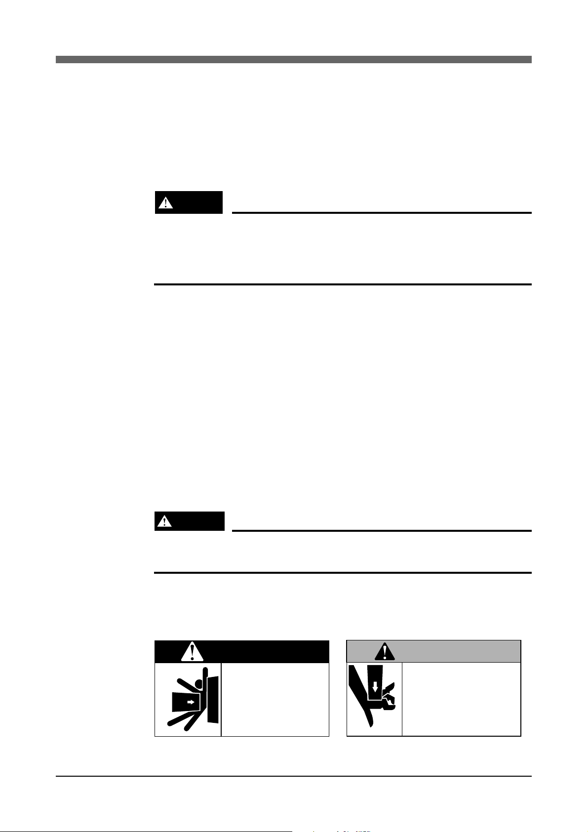
(1) Observe the following cautions during automatic operation
DANGER
Serious injury will result from impact with moving robot.
• Keep outside safeguard enclosure during automatic operation.
• Press the emergency stop button before entering the safeguard enclosure.
The warning label 1 (Fig. 1-1) is attached to the robot.
• Install a safeguard enclosure to keep all personnel from entering within the
movable range of the robot and suffering injury due to being struck by
moving parts.
• Install a safety interlock that triggers emergency stop when the door or
panel is opened.
• Install safeguards so that no one can enter inside except from doors or
panels equipped with safety interlocks.
• The warning label 1 (Fig. 1-1) are supplied with the robot and should be
affixed to conspicuous places on doors or panels equipped with safety interlocks.
(2) Use caution to prevent hands or fingers from being pinched or
crushed.
WARNING
Moving parts can pinch or crush.
Keep hands always from robot arms.
Warning label 2 (Fig. 1-2) is affixed to the robot.
Use caution to prevent hands or fingers from being pinched or crushed in the
robot’s moving parts during transporting the robot or teaching, etc.
DANGER
Serious injury or death
will result from impact
with moving robot.
• Keep outside of guard
during operation.
• Lock out power before
approaching robot.
WARNING
Moving parts can
pinch or crush.
Keep hands away
from robot arms.
Fig. 1-1 Warning label 1 Fig. 1-2 Warning label 2
1-2
Page 15
Chapter 1 Using the Robot Safely
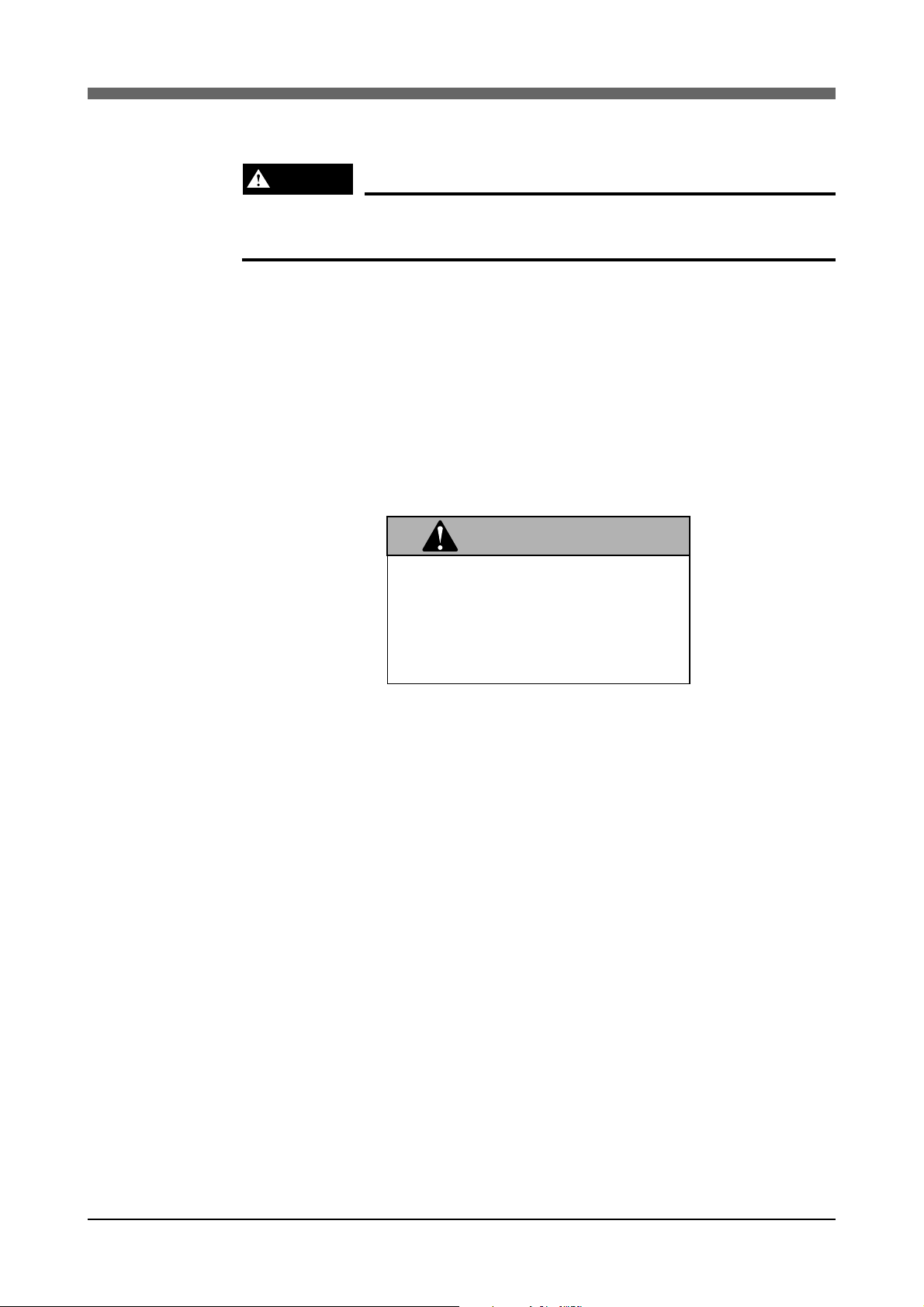
(3) Follow the instructions listed on warning labels and in this
manual.
WARNING
Improper installation or operation can result in serious injury. Read the
Instruction Manual and all warning labels before operation.
The warning label 3 (Fig. 1-3) is attached to the robot.
• Be sure to read the warning labels and this manual carefully and make sure
to thoroughly understand the contents before attempting installation and
operation of the robot.
• Before starting robot operation, be sure to reread the procedures and cautions related to the work as well as the descriptions in this chapter (Chapter
1. “Using the Robot Safely”).
• Never install, adjust, inspect, service or operate the robot in any manner
that does not comply with the instructions in this manual.
WARNING
Improper Installation or operation
can result in serious injury or
death.
Read owner's manual and all
warning labels before operation.
Fig. 1-3 Warning label 3
1-3
Page 16

Chapter 1 Using the Robot Safely
(4) Do not use the robot in environments containing inflammable
gas, etc.
WARNING
• This robot is not designed for operation in environments where inflammable of explosive substances are present.
• Do not use the robot in environments containing inflammable gas,
dust or liquids.
Explosions or fire might otherwise result.
(5) Do not use the robot in locations possible subject to electro-
magnetic interference, etc.
WARNING
Avoid using the robot in locations subject to electromagnetic interference, electrostatic discharge or radio frequency interference.
Malfunctions might otherwise occur.
(6) Use caution when releasing the brake for the Z-axis (vertical axis).
WARNING
The Z-axis will drop when the brake is released, creating a hazardous
situation.
• Press the emergency stop button and prop up the Z-axis with a support
stand, etc., before releasing the brake.
• Be careful not to let your body get caught between the Z-axis and installation base, etc., when releasing the brake to perform direct teaching.
(7) Provide safety measures for end effector (gripper, etc.)
WARNING
• End effectors must be designed and manufactured so that they create
no hazards (for example, a workpiece that comes loose) even if power
(electricity, air pressure, etc.) is shut off or a power fluctuation occurs.
• If there is a possible danger that the object gripped by the end effector
may fly off or drop, then provide appropriate safety protection taking
into account the object size, weight, temperature and chemical properties.
1-4
Page 17

Chapter 1 Using the Robot Safely
(8) Movement of Z-axis at controller power shut off and emergency
stop (for ZAS)
WARNING
The Z-axis will start to rise when the controller power is shut off, the PLC
power is shut off, the program is reset, emergency stop is applied, and
when the supply of air to the Z-axis air cylinder’s solenoid valve is started.
• Take care not to pinch or crush hands, etc., in the Z-axis moving sections.
• If there are any interferences in the Z-axis' upward travel path, reevaluate
the robot position, except for emergencies.
(9) Pay attention to interference of Z-axis with peripheral devices
(for ZAS)
WARNING
If the Z-axis interferes with a peripheral device and stops, there is a risk of
pinching hands, etc., when the interfering object is removed as the Z-axis
will suddenly move.
• Turn the controller power OFF and stop the air supply before removing
the interfering object.
• The Z-axis will naturally drop, so prop it up with a support stand, etc.,
before stopping the air supply.
(10)Z-axis movement when air supply is stopped
WARNING
The Z-axis will drop when the air supply is stopped, creating a hazardous
situation.
Prop up the Z-axis with a support stand, etc., before turning the controller
power OFF and stopping the air supply.
(11) Use caution when disassembling and replacing the pneumatic
devices
WARNING
If the pneumatic devices are disassembled or replaced while the air is
supplied, the parts or air could scatter.
• Turn the controller power OFF, stop the air supply and release all residual pressure from the pneumatic devices before starting work.
• The Z-axis will naturally drop, so prop it up with a support stand, etc.,
before stopping the air supply.
1-5
Page 18

Chapter 1 Using the Robot Safely
(12)Use caution when disassembling and replacing the motor
WARNING
When disassembling or assembling the motor for a ball-screw drive type
robot, a strong magnetic attraction force will be present between the motor
stator (fixed coil) and rotor (rotating magnet), causing a risk of pinching
hands, etc.
A YAMAHA-trained operator must carry out this work using the YAMAHArecommended jigs.
(13)Use caution when removing the Z-axis brake
WARNING
The Z-axis will naturally drop when the brake is removed, causing a hazardous situation.
• Prop up the Z-axis with a support stand, etc., before turning the control
power OFF and removing the brake.
• Be careful not to let your body get caught between the Z-axis drive
section and Z-axis installation base, etc.
(14)Take the following safety precautions during inspection of the
controller
WARNING
• If the terminals or connectors on the outside of the controller must be
touched during inspection, etc., always first turn the controller power
OFF and the power source to prevent possible electrical shock.
• Refer to the "YAMAHA Robot Controller Instruction Manual" for precautions on handling the controller. Never touch any internal parts of
the controller.
(15)Consult YAMAHA for corrective action when the robot is dam-
aged or malfunctions occur.
WARNING
If any part of the robot is damaged or any malfunction occurs, continuing
the operation may be very dangerous. Please consult your YAMAHA sales
office or dealer for corrective action.
Damage or Trouble Possible Danger
Damage to machine harness or robot cable Electrical shock, malfunction of robot
Damage to exterior of robot Flying outward of damaged parts during
robot operation
Abnormal operation of robot (positioning error,
excessive vibration, etc.)
Z-axis brake trouble
1-6
Malfunction of robot
Dropping of load
Page 19

Chapter 1 Using the Robot Safely
(16)Use caution not to touch the controller rear panel cooling fan
WARNING
• Injury may occur from coming into contact with the cooling fan while it
is rotating.
• When removing the fan cover for inspection, first turn OFF the controller and make sure that the fan has stopped.
(17)Be careful not to touch the motor or speed reduction gear cas-
ing when hot.
WARNING
The motor and speed reduction gear casing are extremely hot after automatic operation, so burns may occur if these are touched.
• Before handling these parts during inspection or servicing, turn the
controller power OFF, wait for a while and check that the part has cooled.
(18)Do not remove, alter or stain the warning labels
WARNING
If the warning labels are removed or difficult to see, then essential precautions might not be taken resulting in accidents.
• Do not remove, alter or stain the warning labels on the robot.
• Do not allow the warning labels to be hidden by devices installed onto
the robot by the user.
• Provide proper lighting so that the symbols and instructions on the
warning labels can be clearly seen even from outside the safeguard
enclosure.
(19)Protective connections
WARNING
Be sure to ground the robot and controller to prevent electrical shock.
(20)Be sure to make correct parameter settings - Part 1
!
CAUTION
Always input the correct parameters matching the payload and stroke (working
envelope) before operating the robot.
1-7
Page 20

Chapter 1 Using the Robot Safely
(21)Be sure to make correct parameter settings - Part 2
!
CAUTION
When using a rotary axis (RF, RH, etc.) the robot must be operated with the
tolerable moment of inertia and correct acceleration coefficients according to
the tip mass and moment of inertia. If these are not correct, the drive unit service life may end prematurely, and damage to robot parts or residual vibration
during positioning may result.
(22) Do not use the robot for tasks requiring motor thrust.
!
CAUTION
Avoid using the belt-driven type robots for tasks that utilize motor thrust (press
fitting, burr removal, etc.).
These tasks may cause malfunctions in the robot.
1-8
Page 21

Chapter 1 Using the Robot Safely
3
Special Training for Industrial Robot Operation
Companies or factories using industrial robots must make sure that every person,
who handles the robot such as for teaching, programming, movement check, inspection, adjustment and repair, has received appropriate training and also has
the skills needed to perform the job correctly and safely.
Since YAMAHA Cartesian Robot XY Series falls under the industrial robot category, the user must observe local regulations and safety standards for industrial
robots, and provide special training for every person involved in robot-related
tasks (teaching, programming, movement check, inspection, adjustment, repair,
etc.).
1-9
Page 22

Chapter 1 Using the Robot Safely
4 Robot Safety Functions
(1) Overload detection
This function detects an overload applied to the motor and shuts off the servo
power.
(2) Overheat detection
This detects an abnormal rise in the controller driver temperature and shuts
off the servo power.
If an overload or overheat error occurs, take the following measuring.
1. Insert a timer in the program.
2. Reduce the acceleration coefficient.
(3) Soft limits
Soft limits can be set on each axis to limit the working envelope in manual
operation after return-to-origin and during automatic operation. Note that
the working envelope is the area limited by soft limits.
(4) Mechanical stoppers
If the servo power is suddenly shut off during high-speed operation by emergency stop or safety functions, these mechanical stoppers prevent the axis
from exceeding the movable range.
No mechanical stopper is provided on the R-axis.
Note that the movable range is the area limited by the mechanical stoppers.
(5) Z-axis (vertical axis) brake
An electromagnetic brake is installed on the Z-axis to prevent the Z-axis
from dropping when the servo power is shut off. This brake is working when
the controller power is OFF or if the Z-axis servo is OFF even when the
controller power is ON.
The Z-axis brake can be released by means of the programming unit or by a
command in the program when the controller power is ON.
WARNING
The Z-axis will drop when the brakes are released, creating a hazardous
situation.
• Press the emergency stop button and prop up the Z-axis with a support
stand, etc., before releasing the brake.
• Be careful not to let your body get caught between the Z-axis and installation base, etc., when releasing the brake to perform direct teaching.
1-10
Page 23

Chapter 1 Using the Robot Safely
5 Safety Measures for the System
When the robot is commonly used in conjunction with an automated system,
dangerous situations are more likely to occur from the automated system than
from the robot itself. Appropriate safety measures must be taken on the part of
the system manufacturer according to the individual system.
The system manufacture should provide a proper instruction manual for safe,
correct operation and servicing of the system.
1-11
Page 24

Chapter 1 Using the Robot Safely
6 Trial Run
After making installations, adjustments, inspections, maintenance or repairs to
the robot, carry out trial run using the following procedures.
(1) If a safeguard enclosure has not yet been provided right after installa-
tion of the robot, rope off or chain off the movable range in place of
the safeguard enclosure, and observe the following points.
1. Use sturdy, stable posts that will not fall over easily.
2. The rope or chain should be easily visible by everyone around the robot.
3. Place a sign to keep the operator or other personnel from entering the
movable range.
(2) Check the following points before turning the controller ON.
1. Is the robot securely and correctly installed?
2. Are the electrical connections to the robot correct?
3. Are items such as air pressure correctly supplied?
4. Is the robot correctly connected to peripheral devices?
5. Have safety measures (safeguard enclosure, etc.) been taken?
6. Does the installation environment meet the specified standards?
(3) After the controller power is turned ON, check the following points
from outside the safeguard enclosure.
1. Does the robot start and stop as intended? Can the operation mode be
selected correctly?
2. Does each axis move as intended within the soft limits?
3. Does the end effector move as intended?
4. Are the signal transmissions to the end effector and peripheral devices
correct?
5. Does emergency stop work?
6. Are the teaching and playback functions normal?
7. Are the safeguard enclosure and interlock working as intended?
8. Does the robot move correctly during automatic operation?
1-12
Page 25

Chapter 1 Using the Robot Safely
7 Work Within the Safeguard Enclosure
(1) When work is required in the safeguard enclosure, always turn the
controller power OFF and place a sign indicating that the robot is
being adjusted or serviced in order to keep any other personnel from
touching the controller power switch or operation panel, except for
the following cases.
1) Soft limit settings
2) Teaching
For item 1), follow the precautions and procedure for each section.
To perform item 2), refer to the description in (2) below.
(2) Teaching
When performing teaching within the safeguard enclosure, comply with the
instructions listed below.
1) Check or perform the following points from outside the safeguard enclosure.
1. Make sure that no hazards are present within the safeguard enclosure
by a visual check.
2. Check that the programming unit MPB or TPB operates correctly.
3. Check that no failures are found in the robot.
4. Check that emergency stop works correctly.
5. Select teaching mode and prohibit automatic operation.
2) Never enter the movable range of the robot while within the safeguard
enclosure.
1-13
Page 26

Chapter 1 Using the Robot Safely
8 Automatic Operation
(1) Check the following before starting automatic operation.
1. No one is within the safeguard enclosure.
2. The programming unit or tools, etc., are in their specified location.
3. The alarm or error lamps, etc., on the robot and peripheral devices do not
flash.
4. The safeguard enclosure is securely installed with safety interlocks, etc.,
actuated.
(2) Observe the following during automatic operation or in cases where
an error occurs.
1) After automatic operation has started, check the operation status and warning lamps to ensure that the robot is in automatic operation.
2) Never enter the safeguard enclosure during automatic operation.
3) If an error occurs in the robot or peripheral devices, observe the following
procedures before entering the safeguard enclosure.
1. Press the emergency stop button to set the robot to emergency stop.
2. Place a sign on the start switch indicating that the robot is being in-
spected in order to keep any other person from touching the start switch
and restarting the robot.
9 Adjustment and Inspection
WARNING
Do not attempt any installation, adjustment, inspection or maintenance
unless described in this manual. Unexpected accidents or troubles may
otherwise result.
10 Repair and Modification
WARNING
Do not attempt any repair, part replacement or modification unless described in this manual. These matters require technical knowledge and
skills, and may also involve work hazards.
1-14
Page 27

11 Warranty
The YAMAHA robot and/or related product you have purchased are warranted
against the defects or malfunctions as described below.
Warranty description : If a failure or breakdown occurs due to defects
Warranty Period :The warranty period ends when any of the fol-
Chapter 1 Using the Robot Safely
in materials or workmanship in the genuine parts
constituting this YAMAHA robot and/or related
product within the warranty period, then
YAMAHA will repair or replace those parts free
of charge (hereafter called "warranty repair").
lowing applies:
1) After 18 months (one and a half year) have
elapsed from the date of shipment
2) After one year has elapsed from the date of
installation
3) After 2,400 hours of operation
Exceptions to the Warranty
Failures resulting from the following causes are not covered by warranty repair.
1) Damage due to earthquakes, storms, floods, thunderbolt, fire or any other
natural or man-made disasters.
2) Troubles caused by procedures prohibited in this manual.
: This warranty will not apply in the following
cases
1) Fatigue arising due to the passage of time,
natural wear and tear occurring during operation (natural fading of painted or plated
surfaces, deterioration of parts subject to
wear, etc.)
2) Minor natural phenomena that do not affect
the capabilities of the robot and/or related
product (noise from computers, motors, etc.).
3) Programs, point data and other internal data
that were changed or created by the user.
3) Modifications to the robot and/or related product not approved by
YAMAHA or YAMAHA sales representatives.
4) Use of any other than genuine parts and specified grease and lubricants.
5) Incorrect or inadequate maintenance and inspection.
6) Repairs by other than authorized dealers.
1-15
Page 28

Chapter 1 Using the Robot Safely
YAMAHA MOTOR CO., LTD. MAKES NO OTHER EXPRESS OR IMPLIED
WARRANTIES, INCLUDING ANY IMPLIED WARRANTY OF
MERCHANTABILITY OR FITNESS FOR ANY PARTICULAR PURPOSE.
THE WARRANTY SET FORTH ABOVE IS EXCLUSIVE AND IS IN LIEU
OF ALL EXPRESSED OR IMPLIED WARRANTIES, INCLUDING WARRANTIES OF MERCHANTABILITY, FITNESS FOR A PARTICULAR PURPOSE,
OR WARRANTIES ARISING FROM A COURSE OF DEALING OR USAGE
OF TRADE.
YAMAHA MOTOR CO., LTD. SOLE LIABILITY SHALL BE FOR THE DELIVERY OF THE EQUIPMENT AND YAMAHA MOTOR CO., LTD. SHALL
NOT BE LIABLE FOR ANY CONSEQUENTIAL DAMAGES (WHETHER
ARISING FROM CONTRACT, WARRANTY, NEGLIGENCE OR STRICT
LIABILITY). YAMAHA MOTOR CO., LTD. MAKES NO WARRANTY WHATSOEVER WITH REGARD TO ACCESSORIES OR PARTS NOT SUPPLIED
BY YAMAHA MOTOR CO., LTD.
12 CE Marking
Refer to the following YAMAHA Robot Controller Instruction Manuals for details on the related CE Marking for export to or use in EU regions.
• QRCX-E Instruction Manual
• ERCX/SRCX/DRCX compatible with CE marking supplement manual
1-16
Page 29

CHAPTER 2
Product Outline
1 Robot ......................................................................................2-1
2 Names of each part ................................................................2-2
3 Robot Controller .....................................................................2-7
Page 30

MEMO
Page 31

1 Robot
The robot is configured of the standard function X/Y axes (horizontal cartesian
slide) and optional function Z-axis (vertical slide) and R-axis (rotation).
These configuration axes can move in the following manner. High-accuracy and
high-speed work can be carried out over a wide range by installing work tools.
(+) and (-) indicate the jog key movement directions. (Default settings)
Chapter 2 Product Outline
Y-axis arm movement
Z-axis (vertical)
(-)
(-)
(+)
(+)
R-axis (rotation)
(-)
(+)
(+)
(-)
X-axis arm movement
Robot movements (with ZR axes)
2-1
Page 32

Chapter 2 Product Outline
2 Names of each part
■ Arm type with cable carrier
Y-axis
Y-axis stroke cover
Frame bracket
X-axis motor
Robot cable
Y-axis wiring box
Y-axis motor
Cable carrier between XY
(The machine harness between XY
is wired inside)
X-axis slider
X-axis wiring box
■ Arm type with whipover cable
Y-axis
Y-axis stroke cover
X-axis stroke cover
X-axis
Y-axis slider (tool installation section)
Frame bracket
X-axis motor
Robot cable
X-axis wiring box
Y-axis motor
whipover cable between XY
X-axis slider
X-axis stroke cover
X-axis
Y-axis wiring box
Y-axis slider
(tool installation section)
2-2
Page 33

■ Gantry type
Chapter 2 Product Outline
Support axis
installation bracket
X-axis motor
Robot cable
Y-axis wiring box
Frame bracket
Support axis
Y-axis
Y-axis stroke cover
Y-axis motor
Cable carrier between XY
(The machine harness between XY
is wired inside)
X-axis stroke cover
X-axis
Y-axis slider (tool installation section)
X-axis wiring box
X-axis slider
2-3
Page 34

Chapter 2 Product Outline
■ Moving arm type (with cable carrier)
Y-axis wiring box
Y-axis wiring box
Cable carrier between XY
(The machine harness between XY is wired inside)
X-axis stroke cover
X-axis
X-axis slider
X-axis wiring box
X-axis motor
■ Moving arm type (with whipover cable)
Y-axis whipover cable
Y-axis bracket
(tool installation section)
Y-axis
Y-axis stroke cover
Y-axis motor
Y-axis wiring box
X-axis wiring box
X-axis motor
X-axis slider
X-axis stroke cover
X-axis
Y-axis motor
whipover cable
between XY
Y-axis bracket
(tool installation section)
Y-axis stroke cover
Y-axis
2-4
Page 35

■
Pole
-type with cable carrier
Chapter 2 Product Outline
Y-axis motor
Y-axis slider
(tool installation section)
Y-axis stroke cover
■
Y-axis
Robot cable
Pole
-type with whipover cable
Y-axis relay harness
Y-axis wiring box
Cable carrier between XY
(The machine harness between XY is wired inside)
X-axis stroke cover
X-axis
X-axis slider
X-axis wiring box
X-axis motor
Independent cable
between XY
Robot cable
X-axis wiring box
X-axis motor
X-axis slider
Y-axis slider
(tool installation section)
X-axis stroke cover
Y-axis motor
Y-axis
X-axis
2-5
Page 36

Chapter 2 Product Outline
■ XZ-type with cable carrier
Cable carrier between XY
(The machine harness between XZ
is wired inside)
Z-axis
Z-axis wiring box
Z-axis motor
X-axis wiring box
Robot cable
X-axis
X-axis motor
■ XZ-type with whipover cable
Z-axis slider
Z-axis cover stroke
X-axis stroke cover
whipover cable between XY
X-axis wiring box
Robot cable
X-axis
X-axis motor
Z-axis
Z-axis motor
Z-axis slider
X-axis stroke cover
2-6
Page 37

3 Robot Controller
A RCX40, QRCX, TRCX or DRCX Series robot controller is enclosed with the
XY-X Series according to the user’s order.
Refer to the separate “YAMAHA Robot Controller Instruction Manual” for details on the robot controller.
Chapter 2 Product Outline
DRCX
P
O
W
E
R
C
P
U
O
K
S
E
R
V
O
A
L
A
R
M
QRCX
TRCX
MOTOR
PWR
SRV
XM
ERR
ROB
I/O
XY
YM
ROB
I/O
ZR
ZM
SAFETY
RM
MPB
COM
STD.DIO
OP.1 OP.3
OP.2 OP.4
RCX40
BATT
X
Y
Z
R
RGEN
P
N
ACIN
L
N
RCX40
Robot Controller
2-7
Page 38

MEMO
2-8
Page 39

CHAPTER 3
Preparing the Robot
1 Robot Installation Environment ............................................... 3-1
2 Unpacking the Robot ..............................................................3-2
3 Checking the Product .............................................................3-3
4 Transporting the Robot ...........................................................3-5
5 Installation ..............................................................................3-7
5-1 Installation base ............................................................................... 3-7
5-2 Installing the Robot .......................................................................... 3-8
6 Protective connections ...........................................................3-9
7 Connecting the Robot Cables ............................................... 3-10
7-1 Connecting with the DRCX controller ............................................ 3-12
7-2 Connecting with the TRCX controller ............................................. 3-14
7-2-1 3-axis model .................................................................................. 3-14
7-2-2 4-axis model .................................................................................. 3-16
7-3 Connecting to the QRCX or RCX40 controller ............................... 3-18
8 Installing the Tool ..................................................................3-20
9 User Wiring and User Piping ................................................3-21
10 Setting the Robot ..................................................................3-22
10-1 Setting the payload ........................................................................ 3-22
10-2 Setting the maximum speed .......................................................... 3-23
10-3 Setting the acceleration ................................................................. 3-24
11 Absolute Reset .....................................................................3-25
Page 40

MEMO
Page 41

Chapter 3 Preparing the Robot
1 Robot Installation Environment
WARNING
Avoid installing the robot in locations where the ambient conditions may
exceed the allowable ambient temperature or relative humidity, or in environments where excessive moisture, corrosive gas, metallic powder or
dust is generated.
Malfunctions, failures or short circuits may otherwise result.
WARNING
• This robot is not designed for operation in environments where inflammable of explosive substances are present.
• Do not use the robot in environments containing inflammable gas, dust
or liquids.
Explosions or fire might otherwise result.
WARNING
Do not use the robot in locations subject to excessive vibration. Robot
installation bolts may otherwise become loose causing the robot to fall
over.
!
CAUTION
Avoid using the robot in locations subject to electromagnetic interference, electrostatic discharge or radio frequency interference.
Malfunctions might otherwise occur.
Always install the robot in the following type of environment.
Item Specifications
Allowable ambient temperature 0 to 40°C
Allowable ambient relative humidity
Altitude 0 to 1000m above mean sea level
Ambient environment
Vibration
Air supply pressure, etc.
Working space
35 to 80%RH (with no dew condensation)
Avoid installing near water, cutting water, oil, dust,
metallic chips or organic solvent.
Avoid installing near corrosive gas or corrosive materials.
Avoid installing in
dust or fluid.
Avoid installing near objects causing electromagnetic
interference, electrostatic discharge or radio frequency
interference.
Do not subject robot to impact or vibration.
Supply clean dry air, that does not contain deteriorated
compressor oil, etc., at a pressure within 0.58MPa
(6.0kgf/cm2).
The air filter filtering degree must be 40µm or less.
Allow sufficient space so that work (teaching, inspection,
repairs, etc.) can be carried out safely.
atmosphere containing inflammable gas,
Refer to the “YAMAHA Robot Controller Instruction Manual” for details on the
controller installation conditions.
3-1
Page 42

Chapter 3 Preparing the Robot
2 Unpacking the Robot
WARNING
The robot and robot controller are heavy. Take care not to drop these
parts or damage the devices while unpacking the packages.
The packages are divided into the robot (XY-X Series), robot controller (RCX40,
QRCX, TRCX or DRCX Series) and accessories according to the items ordered
by the user.
Carefully unpack the packages while taking care not to damage the devices.
Robot (XY-X Series)
Robot controller
(RCX40, QRCX, TRCX or DRCX Series)
Example of packaging state
3-2
Accessories
Page 43

3 Checking the Product
!
CAUTION
Contact your YAMAHA dealer immediately if any parts are missing or have
been damaged during transportation.
After unpacking, check the state of the components and the product.
An example of the common combination of components is shown below. Check
the products according to the actual order.
Example of combination with RCX40 controller
Chapter 3 Preparing the Robot
ZR-axis unit (option)
I/O connector set for user
OWNER'S MANUAL
RCX40 controller
Robot (XY-X Series)
Robot cable
Controller power connector
Terminator
STD I/O connector
OP DI, OP DO connector
(option)
MPB programming unit (option)
3-3
Warning labels
Page 44

Chapter 3 Preparing the Robot
OWNER'S MANUAL
Example of combination with TRCX controller
Z-axis unit (option)
Robot (XY-X Series)
I/O connector set for user
Robot cable
TRCX controller
TPB programming unit
(option)
Example of combination with DRCX controller
OWNER'S MANUAL
Y
A
M
A
H
A
Y
A
M
A
H
A
M
O
T
O
R
C
O
.
,
L
T
D
I/O connector set for user
Controller power
connector
Terminator
Warning labels
STD I/O connector
OP DI, OP DO connector
(option)
Robot (XY-X Series)
DRCX connector
TPB programming unit
(option)
Robot cable
Controller power
connector
Y
A
M
A
H
A
Y
A
M
A
H
A
M
O
T
O
R
C
O
., L
T
D
I/O connector
Warning labels
3-4
Page 45

4 Transporting the Robot
WARNING
Serious injury may occur if the robot being transported falls and pins
someone under it.
• Use a hoist and rope with transporting capacity strong enough to support the robot weight.
• Make sure the rope stays securely on the hoist hook.
• Remove all loads attached to the robot end. If any load is still attached,
the robot balance may shift while being transported, and the robot may
topple over causing accidents.
• Always wear a safety helmet, safety shoes and gloves during this work.
• When transporting the robot by equipment such as a forklift, which
requires a license, only properly qualified personnel may operate such
equipment. The equipment and tools used for transporting the robot
should be serviced daily.
Chapter 3 Preparing the Robot
WARNING
Hands and fingers could get caught and serious injury could result if the
slider moves while transporting the robot.
Accidents could also result if the weight balance shifts and the robot drops,
etc.
• Fix the slider with a rope, etc., to prevent movement during transportation.
• Do not place fingers between frame and cover during transportation.
• Do not tilt the robot during transportation.
WARNING
Observe the following precautions when temporarily installing the robot.
Failure to observe these could cause injuries to hands or fingers if the
robot tilts over.
• Always fix the robots with bolts even when only temporarily installing
the robot.
• When temporarily installing the arm type without using bolts, set a
spacer under the arm, etc., to prevent the robot from tilting over. Make
sure that the spacer has sufficient strength and stability.
• The
pole
-type robot’s stability is especially poor, so take special care
to prevent tilting during temporary installation.
3-5
Page 46

Chapter 3 Preparing the Robot
Use of a hoist, dolly or forklift is recommended for transporting the robot or
controller. Use sufficient caution when transporting robots with a long stroke or
large payload as they are heavy.
3-6
Page 47

5 Installation
5-1 Installation base
WARNING
If the installation base is not sufficiently rigid and stable, vibration (resonance) may occur during operation and adversely affect the robot work.
In worst cases the robot might even fall over causing a serious accident.
!
CAUTION
If the installation surface accuracy is insufficient, the robot positioning accuracy
and machine life may drop, and noise may be generated.
1) Select an installation base that has sufficient rigidity and stability to withstand the robot (including tool) and workpiece weight and the reaction generated during operation.
Chapter 3 Preparing the Robot
2) The installation base surface must be machined to a flatness within ±0.05mm/
500mm.
3) If there is a clearance between the installation base and robot frame when the
robot is set on the base, insert suitably thick shims in the clearance to prevent
stress from being applied on the robot frame.
4) Avoid fixing the robot onto the installation base with less than the specified
number of bolts, or installing only one end of the robot. Failure to observe
this could lead to an increase in robot vibration and decrease in positioning
accuracy.
3-7
Page 48

Chapter 3 Preparing the Robot
5-2 Installing the Robot
Always observe the safety precautions and the following procedures to ensure
that the robot is correctly and safety installed.
WARNING
• Take care not to pinch hands, etc., when removing the hoist belt from
the X-axis.
• The robot could tilt over if the hoist belt comes undone and if the balance is lost. Prevent tilting by suspending the tilting section with a
hoist or by using spacers, etc.
1) Tap or hole is machined into the installation base where the robot is to
be secured.
Refer to the XY-X Series catalog for the machining dimensions and positions.
2) Fix the installation base at the specified position.
Securely fix the installation base so that it will not sway during robot operation. (Depending on the installation place or installation base shape, this step
may be carried out after the robot is fixed onto the installation base.)
3) Using a hoist, carefully place the robot onto the installation base.
4) Remove the hoist belt from the Robot.
5) Install the robot referring the explanation for each robot in Chapter 6
and following.
3-8
Page 49

6 Protective connections
WARNING
Be sure to ground the robot and controller to prevent electrical shock.
WARNING
Turn the controller power OFF before starting connecting the ground.
The ground terminal position differs for each robot. Refer to the explanation for
each robot in Chapter 6 and following for details.
1) Provide a terminal marked “PE” as the protective conductor for the entire
system, and connect to an external protective conductor. Also securely connect the ground terminal on the robot base to the protective conductor.
(Symbol 417-IEC-5019)
Chapter 3 Preparing the Robot
2) When the end effector uses an electrical device which, if it malfunctions,
might make contact with the power supply, the user must provide proper
grounding on his own responsibility. The XY-X series robots do not have a
ground terminal for this purpose.
3) For details on protective bonding on the robot body to comply with CE marking, follow the instructions on protective bonding explained in the "YAMAHA
QRCX-E robot controller owner's manual".
3-9
Page 50

Chapter 3 Preparing the Robot
7 Connecting the Robot Cables
WARNING
1. The robot cable is the most important cable for controlling the robot. If
the connector is insufficiently connected and there are pin contact
faults, the robot could malfunction. Confirm that each connector is
securely connected before turning the controller power ON.
2. Arrange the connected cables so that they will not get in the way of
robot movements or the operator’s operations. Make sure that excessive load is not applied on the connector due to pulling of the cables.
WARNING
• Before connecting the cables, check that there are no bends or breaks
in the robot cable connector pins and that the cables are not damaged.
Bent or broken pins or cable damage may cause robot malfunctions.
• Turn the controller power OFF before connecting the controller and
robot cable.
WARNING
With the RCX40, QRCX and TRCX4 controllers, the motor connectors XM
and ZM, YM and RM and Robot I/O connectors XY and ZR have the same
shape. Take special care when connecting as incorrect connections could
cause malfunctions.
WARNING
With the TRCX3 controller, the motor connectors XM and ZM have the
same shape. Take special care when connecting as incorrect connections
could cause malfunctions.
WARNING
• If the connector is insufficiently connected and there are pin contact
faults, the robot could malfunction. Confirm that each connector is securely connected before turning the controller power ON.
• Before turning on the controller, check that the robot I/O connector is
securely attached.
• Make sure that excessive load is not applied on the connector due to
pulling of the robot cables.
WARNING
Arrange the robot cable so that it will not get in the way of robot movements. Do not set the area where the robot cable interferes with the load
on the robot tip as the working envelope. If the robot’s moving sections
interfere with the cable, the robot cable could be damaged and malfunctions could occur.
3-10
Page 51

Chapter 3 Preparing the Robot
WARNING
Arrange the connected robot cable so that it will not get in the way of
operator’s operations. The operator could trip on the robot cable and be
injured.
WARNING
When connecting the robot cable, insert the robot cable connector straight
into the mating connector on the controller. Inserting the connector while
tilted might cause the pins to make poor contact, causing robot malfunction and the connector itself might even break.
!
CAUTION
These connectors all work in only one direction. Take a good look at the connector shape before trying to attach it. Connecting the wrong way may damage
the connectors.
The robot cable is connected beforehand to the XY Series robot side.
Correctly install the other end of the robot cable to the robot controller. For details on connections to the robot controller, refer to 7-1 to 7-4.
3-11
Page 52

Chapter 3 Preparing the Robot
7-1 Connecting with the DRCX controller
WARNING
When connecting the robot cable, insert the robot cable connector straight
into the mating connector on the controller. Inserting the connector while
tilted might cause the pins to make poor contact, causing robot malfunction and the connector itself might even break.
!
CAUTION
These connectors all work in only one direction. Take a good look at the connector shape before trying to attach it. Connecting the wrong way may damage
the connectors.
1) Prepare the required tools.
Precision phillips-head screwdriver.
2) While referring to Table 3-1 and Fig.3-1, securely insert the motor connector
into the correct position on the controller unitl a click is heard.
3) While referring to Table 3-1 and Fig.3-1, insert the robot I/O cable into the
correct position on the controller.
4) Use the precision phillips-head screwdriver to tighten the robot I/O connector screws.
Table 3-1
Robot cable DRCX
XM MOTOR X
YM MOTOR Y
XY ROB I/O
3-12
Page 53

Robot cable
MOTOR connector
XM
YM
Chapter 3 Preparing the Robot
XY
ROBOT
I/O connector
DRCX controller
Fig. 3-1 Connection to DRCX controller
To robot
3-13
Page 54

Chapter 3 Preparing the Robot
7-2 Connecting with the TRCX controller
7-2-1 3-axis model
WARNING
When connecting the robot cable, insert the robot cable connector straight
into the mating connector on the controller. Inserting the connector while
tilted might cause the pins to make poor contact, causing robot malfunction and the connector itself might even break.
!
CAUTION
These connectors all work in only one direction. Take a good look at the connector shape before trying to attach it. Connecting the wrong way may damage
the connectors.
!
CAUTION
With the TRCX3 controller, the MOTOR connectors XM and ZM have the same
shape. Take care not to reverse the robot cable XM and ZM when connecting.
1) Prepare the required tools.
Precision phillips-head screwdriver.
2) While referring to Table 3-2 and Fig.3-2, securely insert the motor connector
into the correct position on the controller unitl a click is heard.
3) While referring to Table 3-2 and Fig.3-2, insert the robot I/O cable into the
correct position on the controller.
4) Use the precision phillips-head screwdriver to tighten the robot I/O connector screws.
Table 3-2
Robot cable TRCX
XM MOTOR X
YM MOTOR Y
XY ROB I/O
ZM MOTOR Z
Z ROB I/O
Main side unit
Sub-side unit
3-14
Page 55

ROBOT
I/O connector
MOTOR
connector
Chapter 3 Preparing the Robot
Z
M
Z
MOTOR
connector
XM
YM
X
Y
ROBOT
I/O connector
Robot cable
Fig. 3-2 Connection to TRCX controller (3-axis model)
To robot
3-15
Page 56

Chapter 3 Preparing the Robot
7-2-2 4-axis model
WARNING
When connecting the robot cable, insert the robot cable connector straight
into the mating connector on the controller. Inserting the connector while
tilted might cause the pins to make poor contact, causing robot malfunction and the connector itself might even break.
!
CAUTION
These connectors all work in only one direction. Take a good look at the connector shape before trying to attach it. Connecting the wrong way may damage
the connectors.
!
CAUTION
With the TRCX4 controller, the MOTOR connector and PI connector shapes
are the same for the XY-axis and ZR-axis. Take care not to reverse the robot
cables XY and ZR when connecting.
1) Prepare the required tools.
Precision phillips-head screwdriver.
2) While referring to Table 3-3 and Fig.3-3, securely insert the motor connector
into the correct position on the controller unitl a click is heard.
3) While referring to Table 3-3 and Fig.3-3, insert the robot I/O cable into the
correct position on the controller.
4) Use the precision phillips-head screwdriver to tighten the robot I/O connector screws.
Table 3-3
Robot cable TRCX
XM MOTOR X
YM MOTOR Y
XY ROB I/O
ZM MOTOR X
RM MOTOR Y
ZR ROB I/O
Main side unit
Sub-side unit
3-16
Page 57

ROBOT
I/O connector
MOTOR
connector
Chapter 3 Preparing the Robot
ZM
RM
Z
R
MOTOR
connector
XM
YM
X
Y
ROBOT
I/O connector
Robot cable
Fig. 3-3 Connection to TRCX controller (4-axis model)
To robot
3-17
Page 58

Chapter 3 Preparing the Robot
7-3
Connecting to the QRCX or RCX40 controller
WARNING
When connecting the robot cable, insert the robot cable connector straight
into the mating connector on the controller. Inserting the connector while
tilted might cause the pins to make poor contact, causing robot malfunction and the connector itself might even break.
!
CAUTION
These connectors all work in only one direction. Take a good look at the connector shape before trying to attach it. Connecting the wrong way may damage
the connectors.
!
CAUTION
With the RCX40, QRCX controller, the MOTOR connector and PI connector
shapes are the same for the XY-axis and ZR-axis. Take care not to reverse the
robot cables XY and ZR when connecting.
1) Prepare the required tools.
Precision phillips-head screwdriver.
2) While referring to Table 3-4 and Fig.3-4, Fig.3-5, securely insert the motor
connector into the correct position on the controller unitl a click is heard.
3) While referring to Table 3-4 and Fig.3-4, Fig.3-5, insert the robot I/O cable
into the correct position on the controller.
4) Use the precision phillips-head screwdriver to tighten the robot I/O connector screws.
Table 3-4
Robot cable RCX40, QRCX
XM MOTOR1 (X side)
YM MOTOR1 (Y side)
ZM
RM
XY
ZR PI2
MOTOR2 (Z side)
MOTOR2 (R side)
PI1
Note)This is for the main robot.
Refer to the controller instruction manual for details.
3-18
Page 59

Chapter 3 Preparing the Robot
1
2
XM
YM
ZM
RM
Robot cable
XY
ZR
Connect to YAMAHA robot
Fig. 3-4 Connection to QRCX controller
XM
YM
ZM
XY
ZR
RM
Connect to YAMAHA robot
Fig. 3-5 Connection to RCX40 controller
3-19
Page 60

Chapter 3 Preparing the Robot
8 Installing the Tool
WARNING
The user must responsibly determine the bolt type and tightening torque
for the tool installation, and must accurately tighten these. Improper installation could cause the tool to dislocate during operation and lead to
serious accidents.
!
CAUTION
Install the tool at the designated section. Avoid installing heavy objects on the
other sections (Y-axis frame or X-axis slider, etc.).
Failure to observe this could lead to vibration during operation (especially during positioning).
Install user's tools on the sections designated as tool installation sections, such as
the robot slider and bracket. (Refer to Chapter 2 2. Names of each part and explanations for each robot in Chapter 6 and following for each robot for details on the
designated sections.)
Refer to the explanation for each robot in Chapter 6 and following for details on
the actual installation methods.
3-20
Page 61

9 User Wiring and User Piping
!
CAUTION
Do not clamp the wires or pipes to the outside of the whipover cable. The
whipover cable could sag or break and ultimately be disconnected.
After completing all work up to step 8, wires and pipes are laid from the user’s
devices or robot controller to the tools and valves installed on the robot.
■ Cable carrier type
Carry out wiring and piping using the attached cable carrier.
Refer to the explanation for each robot in Chapter 6 and following for details
on the actual wiring and piping methods and precautions.
The cable carrier contains a user I/O cable (0.3sq×10) for user wiring, so there
is no need to add harnesses and route them through the cable carrier.
Refer to Chapter 3, “12. Specifications” for the specifications on the user I/O
wire, and the explanation of each robot in Chapter 6 for details on the wiring
methods.
Chapter 3 Preparing the Robot
■ whipover cable carrier type
The signal wires (0.3mm2×10 wires) and air tubes (4×2.5×2 tubes) are laid in
the whipover cable beforehand. Use these for wiring and piping to the tools.
Refer to the explanation for each robot in Chapter 6 and following for details
on the actual wiring and piping methods and precautions.
3-21
Page 62

Chapter 3 Preparing the Robot
10 Setting the Robot
10-1 Setting the payload
!
CAUTION
Always input an accurate value as an incorrect value can lead to various trouble including vibration and a drop in machine life.
!
CAUTION
When installing a weight other than the tool or workpiece on the robot’s moving
section, add that weight. (For example, if an air valve is fixed on the Y-axis
frame, include that weight in the payload.)
The optimum acceleration and servo gain, etc., are automatically set for the
cartesian robot XY-X Series by inputting the controller payload parameters.
Set the total value of the tool weight and workpiece weight as a kg unit in the
payload parameter.
■ List of payload parameters
Controller Payload parameter
DRCX PRM90
TRCX3 PRM130
TRCX4 PRM170
RCX40, QRCX Robot parameter "1. Tip weight"
Refer to the following sections in the Robot Controller Instruction Manual, and
set the payload parameters.
For DRCX or TRCX controller
Chapter 5 Parameters
For RCX40 or QRCX controller
Chapter 4 Operation > 12. System Mode > 12-1-1. Robot parameters
3-22
Page 63

10-2 Setting the maximum speed
When operating a ball screw driven robot, the ball screw's free length will increase as the movement stroke increases, and the resonance frequency will drop.
Thus, the ball screw may resonate and generate vigorous vibration depending on
the motor rotation speed. (The speed at which resonance occurs is called the
whirling speed.) To prevent this resonance, the maximum speed setting must be
lowered if the movement stroke increases depending on the robot model.
!
CAUTION
Continuing use while the ball screw is resonating will cause the ball screw to
wear out prematurely.
!
CAUTION
There are cases when the whirling speed is not reached depending on the
movement point. (The ball screw’s nut acts as the support material, so when
operating the robot near the center of the stroke, the ball screw's free length will
be shortened and resonance will not occur as easily.) If resonance does not
occur when the robot is actually operated, the speed can be increased.
Chapter 3 Preparing the Robot
■ Models requiring lower maximum speed setting
FXYX X-axis stroke 750mm or more
SXYX X-axis stroke 750mm or more
MXYX X-axis stroke 850mm or more
HXYX X-axis stroke 850mm or more
Refer to the catalog for the maximum speed setting values.
The maximum speed can be reduced by lowering the speed setting for automatic
operation or by lowering the speed with a program command. The user should
select the suitable method.
Refer to the following sections in the Robot Controller Instruction Manual for
details on changing the speed setting during automatic operation.
For ERCX, SRCX, DRCX or TRCX controller
Chapter 9 Robot Operation > 9-3. Automatic Operation
For RCX40 or QRCX controller
Chapter 4 Operation > 9. "Auto" Mode > 9-6. Changing the automatic movement speed
3-23
Page 64

Chapter 3 Preparing the Robot
10-3 Setting the acceleration
The acceleration is automatically set for the Cartesian robot XY-X Series when
the payload parameter is set, so large vibration will not occur during operation.
However, if the tool or workpiece is greatly offset from the robot, vibration may
occur especially during positioning.
In this case, lower the controller's acceleration setting.
Lowering the acceleration is also effective if tool or workpiece vibration occurs
due to a low tool rigidity.
■ List of acceleration parameters
Controller Acceleration parameter
DRCX X-axis PRM51 Y-axis PRM91
TRCX3 X-axis PRM51 Y-axis PRM91 Z-axis PRM131
TRCX4 X-axis PRM51 Y-axis PRM91 Z-axis PRM131
RCX40, QRCX Axis parameter "1. Acceleration coefficient"
R-axis PRM171
Refer to the following sections in the Robot Controller Instruction Manual, and
change the acceleration.
For DRCX or TRCX controller
Chapter 5 Parameters
For RCX40 or QRCX controller
Chapter 4 Operation > 12. "System" Mode > 12-1-2. Axis parameters
3-24
Page 65

11 Absolute Reset
Refer to this section and set the origin position before using the robot.
The Cartesian robot XY-X Series uses an absolute method position detector, and
thus return-to-origin is not required when the controller power is turned ON again.
However, the origin position must be set the first time the controller power is
turned ON from any of the following states.
(1) When robot cable is connected for the first time after delivery
(2) When the cable connection between the robot cable and controller has
been disconnected
(3) When the absolute battery is not connected
(4) When the motor or cable is replaced
One of the following errors will appear when the power is turned ON in any of
the above cases, but this is not an error. The robot will operate normally when the
power is turned ON again.
Chapter 3 Preparing the Robot
For DRCX or TRCX controller
15: FEEDBACK ERROR 2
23: ABS. BAT. L-VOLTAGE
24: ABS. DATA. ERROR
For QRCX controller
17.80:D?.ABS.Encoder backup error
17.81:D?.ABS.Encoder battery alarm
17.85:D?.ABS.Encoder system error
17.92:D?.ABS.Cable disconnected
17.93:D?.ABS.Data overflow
17.94:D?.ABS.Battery degradation
For RCX40 controller
17.27 : D?.ABS. backup failed (CPU)
17.80 : D?.ABS. backup failed (DRIVER)
17.81 : D?.ABS.battery wire breakage
17.92 : D?.Resolver disconnected during power off
17.93 : D?.Position backup counter overflow
17.94 : D?.ABS.battery low voltage
etc
Note) Question marks (?) in the above error messages indicate the axis num-
bers.
3-25
Page 66

Chapter 3 Preparing the Robot
■ Setting the origin position
[1] For robot configured of only linear movement axis
The above type of robot uses a stroke end detection method as origin return.
The motor side stroke end is set as the origin detection position before shipment from the factory. (Excluding ZH and the Z-axis of ZS, ZRS.)
!
CAUTION
Avoid changing the origin position to the non-motor side as the position could
deviate, trouble could occur, and could be hazardous in some cases. Always
consult with YAMAHA when the origin position must be changed.
Refer to the following sections in the Robot Controller Instruction Manual
and set the origin.
For ERCX, SRCX, DRCX or TRCX controller
Chapter 9 > 9-1. Returning-to-the Origin > 9-1-1. Return-to-origin by the search method
For QRCX controller
Chapter 11 > 11-9. Absolute reset
For RCX40 controller
Chapter 11 > 11-8. Absolute reset
[2] When robot contains a rotary axis
Target rotary axis
RF (R-axis for SXYX/MXYX/SXYBX)
RL/RH (R-axis for HXYX)
RS (R-axis for ZRS unit)
The above rotary axes uses mark method return-to-origin.
Thus, if the robot contains this type of axis, the origin position of the rotary axis
can be set freely by the user.
Refer to the following sections in the Robot Controller Instruction Manual, move
the robot to the preferred origin, and then set the origin.
For DRCX or TRCX controller
Chapter 9 > 9-1. Returning-to-the Origin > 9-1-2. Return-to-origin by the mark method
Return the rotary axis to the origin before returning the other linear movement
axes to the origin. (Refer to section [1] above for details on returning the linear
movement axis to the origin.)
For QRCX controller
Chapter 11 > 11-9. Absolute reset
For RCX40 controller
Chapter 11 > 11-8. Absolute reset
3-26
Page 67

Chapter 3 Preparing the Robot
When MANUAL > RST.ABS > ALL is selected on the MPB screen (see “11-93” in QRCX owner’s manual or “11-8-3” in RCX40 owner’s manual), first perform absolute reset for the rotating axis and then other linearmovement axes.
When performing absolute reset for each axis one by one (see “11-9-2” in QRCX
owner’s manual or “11-8-2” in RCX40 owner’s manual), you can begin in any
order.
3-27
Page 68

Chapter 3 Preparing the Robot
After setting the origin position, attach the label enclosed with the robot so that it
acts as a match mark on the tool side and Robot side. This match mark will be the
reference for subsequent origin settings.
Figure
Slit
Example: ZRS
Origin position label
(enclosed with product)
Example: RH
Origin position label
3-28
Page 69

CHAPTER 4
Periodic Inspections
1 Outline ....................................................................................4-1
2 Precautions ............................................................................. 4-1
3 Daily inspection ......................................................................4-2
4 Three-month inspection ..........................................................4-2
5 Six-month inspection ..............................................................4-3
6 Three-year inspection .............................................................4-4
7 Replenishing the grease .........................................................4-5
8 Maintenance and inspection of harmonic drives ....................4-6
8-1 Harmonic grease replacement period .............................................. 4-7
Page 70

MEMO
Page 71

1 Outline
Implementation of periodic inspections is essential to ensure safe and efficient
operation of the YAMAHA robot.
The periodic inspection items and procedures for the XY Series are described in
this chapter.
The periodic inspections include;
• Daily inspection
• Three-month inspection
• Six-month inspection
• Three-year inspection
Thoroughly understand the details of the inspection and observe the precautions
during this work.
2 Precautions
Chapter 4 Periodic Inspections
Always read the safety precautions in “Chapter 1 Using the Robot Safely” and
follow the instructions. Important precautions are listed below again for reference.
DANGER
• Never enter the robot’s movement area when operating the robot during adjustments and inspections. Pay attention to the robot movements
and surrounding safety so that the emergency stop button can be
pressed immediately when any hazard is sensed.
WARNING
• Always turn the controller power switch and external power distribution board switch OFF before starting adjustments and inspections
that do not require robot operation.
• Press the emergency stop button when robot operation is not required
during the electrical system inspection.
• Use only lubricant designated by YAMAHA or your dealer.
• Use only parts designated by YAMAHA or your dealer when replacing
parts. Make sure that foreign matter does not enter the robot during
adjustment, part replacement or reassembly.
• Never modify the robot or controller, etc. Modifications may result in
improper specifications and may threaten operator safety.
• Always tighten the bolts and screws securely after completing adjustments or inspections.
• During robot adjustment or inspection, place a sign indicating that the
robot is being adjusted or inspected, to prevent others from touching
the switches. Provide a switch key lock mechanism or assign a monitor if necessary.
4-1
Page 72

Chapter 4 Periodic Inspections
3 Daily inspection
Check the following points before and after robot operation every day. Make
adjustments and replacements as necessary.
Check point
Safeguard enclosure
Cables
Motor, speed
reduction gear
Pneumatic devices
Check that the safeguard enclosure is securely
fixed at the designated position.
Check for damages, dents and excessive bending.
Check for the adherence of chemicals.
Check for abnormal vibration or noise, and for
abnormal temperature rise.
• Check that the air pressure is correct.
• Check that there are no air leaks.
• Check that the water has been drained.
• Check that the air filter is not contaminated.
4 Three-month inspection
Check the following points every three months, and replenishing grease if required. (To replace grease, see “7 Replenishing the grease”.)
Check point
• Clean off any dirt or contamination. Replenish
the grease after cleaning.
Replenishment of
grease to X, Y and Z
axis ball screw, linear
guide and ball spline
• Replenish grease if the items on the left are dry
or do not have enough grease.
Standard specifications:
Clean room specifications:
Check items
Check items
Alvania No. 2 (Showa Shell)
Daphne Eponex No. 2 (Idemitsu)
LG-2 (NSK)
!
CAUTION
Use of grease not recommended by YAMAHA may lead to a drop in the ball
screw, linear guide, ball spline and linear bushing shaft life. When using the
clean room specifications, the degree of cleanliness may drop.
4-2
Page 73

5 Six-month inspection
Check the following points every six months, and make adjustments or replacements as required.
Chapter 4 Periodic Inspections
Check point
Robot's main bolts
and screws
X-axis, Y-axis and
Z-axis drive sections
(ball screw, linear
guide)
Z-axis ball spline and
ball screw (for ZS, ZRS)
R-axis timing belt
(for ZRS)
Wiring in robot
Belt
(for FXYBX, SXYBX,
ZRS, HXYLX)
Controller
Controller rear panel
cooling fan
Check items
Check for looseness, and tighten if necessary.
• Check for looseness in the X-axis, Y-axis and
Z-axis drive section (ball screw, linear guide).
Tighten if necessary.
• Check for vibration during operation. Tighten
the drive section, and X-axis, Y-axis and Z-axis
installation bolts if necessary.
• Check for looseness caused by wear. Contact
YAMAHA if any abnormality is found.
Check for looseness.
(Contact YAMAHA if any abnormality is found.)
• Check the timing belt tension.
• Check the timing belt for abnormalities (cracks
or cuts).
• Check the cables for damage.
• Check the relay connectors, etc., for looseness.
• Inspect the timing belt for abnormalities (cracks
or cuts).
• Check the timing belt tension.
• Check the terminals for looseness.
• Check the connection connectors for looseness.
• Check that the fan is rotating.
• Check whether anything is obstructing the fan.
• Check the rotating fan for abnormal sounds.
Check visually if any abnormal sound is heard,
and remove any foreign matter. Contact
YAMAHA if no foreign matter is found.
• Check the fan cover for contamination. Remove
and clean the cover if contaminated.
4-3
Page 74

Chapter 4 Periodic Inspections
g
6 Three-year inspection
Check the following points once every three years, and adjust or replenish grease
as necessary.
If the robot is used frequently, inspect the robot at an earlier stage.
Check point
R-axis speed
reduction gear
X-axis, Y-axis and
Z-axis drive section
(Ball screw nut
section, motor section
and linear guide)
*To replace harmonic drive
Check items
Disassemble and check the harmonic drive.
Replace the grease.*
Check the ball screws, nuts and linear guide for
looseness caused by wear.
rease, see "8 Maintenance and inspection".
4-4
Page 75

7 Replenishing the grease
WARNING
Precautions for handling grease
• Inflammation may occur if the grease gets into eyes.
Always wear protective goggles, etc., to protect eyes when handling
the grease.
• Inflammation may occur if the grease gets on skin. Wear protective
gloves, etc., to protect skin when handling the grease.
• Do not consume the grease. (Consumption of grease will cause diarrhea
and vomiting.)
• Wear protective gloves when opening the can to prevent injury to hands.
• Store the grease out of the reach of children.
• Do not heat the grease or place it near fire. There is a risk of igniting or
fires.
Remedial measures
• If the grease gets into eyes, flush eyes for 15 minutes with clean water,
and then see doctor.
• If the grease gets on skin, wash off completely with water and soap.
• If the grease is consumed, do not induce vomiting, and instead consult with a doctor immediately.
Chapter 4 Periodic Inspections
!
CAUTION
Use of grease not recommended by YAMAHA may lead to a drop in the ball
screw, linear guide, ball spline and linear bushing shaft life. When using the
clean room specifications, the degree of cleanliness may drop.
!
CAUTION
When replenishing clean grease, manually apply a thin coat on the screws and
the entire length of the spline shaft.
Refer to the periodic inspections in the explanation for each robot in Chapter 6
and following, and replenish the grease. Observe the following points when replenishing the grease.
4-5
Page 76

Chapter 4 Periodic Inspections
8
Maintenance and inspection of harmonic drives
WARNING
The motor and speed reduction gear casing are extremely hot after automatic operation, so burns may occur if these are touched. Before handling these parts during inspection or servicing, turn OFF the controller,
wait for a while and check that the part has cooled.
WARNING
Precautions for handling harmonic grease and washing oil
• Inflammation may occur if the grease gets into eyes.
Always wear protective goggles, etc., to protect eyes when handling
the grease.
• Inflammation may occur if the grease gets on skin. Wear protective
gloves, etc., to protect skin when handling the grease.
• Do not consume the grease. (Consumption of grease will cause diarrhea
and vomiting.)
• Wear protective gloves when opening the can to prevent injury to hands.
• Store the grease out of the reach of children.
• Do not heat the grease or place it near fire. There is a risk of igniting or
fires.
Remedial measures
• If the grease gets into eyes, flush eyes for 15 minutes with clean water,
and then see doctor.
• If the grease gets on skin, wash off completely with water and soap.
• If the grease is consumed, do not induce vomiting, and instead consult with a doctor immediately.
WARNING
Disposal of harmonic grease, spent washing oil and waste containers
• Disposal methods are specified by law. Always follow local laws when
disposing of these items.
• Do not apply pressure on an empty container. The container could rupture if pressurized.
• Do not weld, heat, open a hole or cut this container. Failure to observe
this could lead to an explosion and igniting of the residual matter.
!
CAUTION
Use of grease not recommended by YAMAHA could lead to a drop in the harmonic drive life.
4-6
Page 77

Chapter 4 Periodic Inspections
!
CAUTION
Harmonic drive
• Do not apply strong impacts on any part with a hammer, etc. Do not damage
or mark the parts by dropping. There is a risk of damage.
• The specified performance cannot be attained if a damaged part is used.
Continued use of a damaged part could lead to trouble such as rupture.
Harmonic grease HC-1A (Harmonic Drive Systems) is used to lubricate the harmonic drive used for the R-axis (ZRL, ZRH, ZRF unit) speed reduction gear. The
life of the harmonic drive could be shortened if this grease deteriorates.
Determine an inspection interval at every three years or to suit the usage conditions, and replace the grease.
The ZRS unit's R-axis also uses a harmonic drive, but the grease does not need to
be replaced.
8-1 Harmonic grease replacement period
The harmonic grease should be replaced when the total number of wave generator rotations reaches 1.5 × 10⁸ times (at -10°C to +40°C). Thus, the replacement
period will differ according to the following usage conditions.
n : Number of arm movements in one minute
θ : Average arm rotation in one movement
N : 1/deceleration rate
h : Number of operation hours per day
D : Number of operation days per year
The method of calculating the replacement period using the following conditions
is shown as an example.
n : 10 times
θ : 1/4 rotation
N: 80
h : 24 hours/day
D : 240 days/year
Replacement period = 1.5 × 10⁸/ ( n × 60 × h × D × N × θ )
= 1.5 × 10⁸/ ( 10 × 60 × 24 × 240 × 80 × 1/4 )=2.17 years
4-7
Page 78

MEMO
4-8
Page 79

CHAPTER 5
Specifications
1 Specifications .........................................................................5-1
1-1 Robot cable ...................................................................................... 5-1
1-2 User I/O cable .................................................................................. 5-5
Page 80

MEMO
Page 81

1 Specifications
The specifications of each robot's common parts are shown below.
1-1 Robot cable
This cable is used to connect the controller and robot.
Chapter 5 Specifications
Resolver
Brake
Resolver
Brake
Sensor
Signal
S2
S4
S1
XP
S3
r
R1
R2
DG
MB+
XBK
t
MB-
S2
S4
S1
YP
S3
y
R1
R2
DG
MB+
YBK
u
MB-
HLIM
GND24
HLIM
GND24
24V
ORG
ORG
GND24
i
U2
XM
V
o
W
Ring-tongue terminal
FG
U
YM
V
!0
W
Ring-tongue terminal
FG
ConnectionConnector
No
1
2
3
4
5
66
7
1
2
1
2
3
4
5
6
7
1
2
1
2
3
1
2
3
4
1
2
3
!1
4
No
1
2
3
4
5
7
14
16
19
20
XY
21
22
23
24
25
32
34
10
11
28
29
27
30
31
XM
3
4
1
2
3
YM
4
q
w
e
Blue
Orange
Green
Brown
Gray
Red
Green
Black
Yellow
Pink
Purple
White
Blue/Red
Orange/White
Green/White
Green
Brown/White
Gray/White
Green
Green
Red/White
Yellow/Black
Pink/Black
1
2
3
Yellow /Green
4
5
6
WireColor/No.Connector
0.3sq
twisted pair
0.3sq
twisted pair
0.3sq
twisted pair
0.3sq
0.3sq
twisted pair
0.3sq
twisted pair
0.3sq
twisted pair
0.3sq
twisted pair
0.3sq
0.3sq
twisted pair
0.3sq
0.3sq
twisted pair
0.75sq
0.75sq
0.75sq
0.75sq
0.75sq
0.75sq
0.75sq
r
t
y
u
i
o
!0
XP
XBK
YP
YBK
ORG
XM
YM
q
XY
w
XM
e
YM
!1
2-axis robot cable
5-1
Page 82

Chapter 5 Specifications
!
Signal ConnectionConnector
S2
Resolver
S4
S1
S3
R1
R2
DG
MB+
Brake
MB-
S2
Resolver
S4
S1
S3
R1
R2
DG
MB+
Brake
MB-
HLIM
GND24
HLIM
GND24
U2
V
W
FG
U
V
W
FG
XP
y
XBK
u
YP
i
YBK
o
XM
!3
Ring-tongue terminal
YM
!4
Ring-tongue terminal
!5
y
u
i
o
No
1
2
3
4
5
66
7
1
2
1
2
3
4
5
6
7
1
2
1
2
3
4
1
2
3
4
No
1
2
3
4
5
7
14
16
19
20
XY
q
21
22
23
24
25
32
34
10
11
28
29
3
4
1
2
3
4
XM
YM
e
r
Orange/White
Green/White
Brown/White
Yellow/Green
XP
XBK
YP
YBK
WireColor/No.Connector
0.3sq
Blue
twisted pair
Orange
0.3sq
Green
twisted pair
Brown
0.3sq
Gray
twisted pair
Red
0.3sq
Green
0.3sq
Black
twisted pair
Yellow
0.3sq
Pink
twisted pair
Purple
0.3sq
White White
twisted pair
Blue/Red Blue/Red
0.3sq
twisted pair
0.3sq
Green
0.3sq
Green
Green
twisted pair
0.75sq
1
0.75sq
2
0.75sq
3
0.75sq
0.75sq
4
0.75sq
5
0.75sq
6
Gray/White
Signal ConnectionConnector
S2
Resolver
S4
S1
S3
R1
R2
DG
Brake
MB+
MB-
Sensor
24V
ORG
GND24
U2
V
W
FG
Ring-tongue terminal
No
1
2
3
ZP
4
!0
5
66
7
1
ZBK
!1
2
1
ORG
2
!2
3
1
ZM
2
!6
3
4
!7
No
1
2
3
4
5
9
17
Z
18
w
13
12
15
4
ZM
3
t
1
Blue
Orange
Green
Brown
Gray
Red
Green
Black
Yellow
Pink
Yellow/Green
q
w
WireColor/No.Connector
0.3sq
twisted pair
0.3sq
twisted pair
0.3sq
twisted pair
0.3sq
0.3sq
twisted pair
0.3sq
0.3sq
twisted pair
0.75sq
1
0.75sq
2
0.75sq
3
0.75sq
XY
!0
ZP
!1
!2
ZBK
ORG
Z
!3
XM
!4
YM
XM
e
r
!5
YM
!6
ZM
t
ZM
7
3-axis robot cable (For TRCX controller)
5-2
Page 83

Chapter 5 Specifications
Signal ConnectionConnector
S2
Resolver
S4
S1
S3
R1
R2
DG
Brake
MB+
MB-
S2
Resolver
S4
S1
S3
R1
R2
DG
Brake
MB+
MB-
HLIM
GND24
HLIM
GND24
U2
V
W
Ring-tongue terminal
FG
U
V
W
Ring-tongue terminal
FG
No
1
2
3
XP
4
y
5
66
7
1
XBK
u
2
1
2
3
YP
4
i
5
6
7
1
YBK
o
2
1
XM
2
!3
3
4
1
YM
2
!4
3
4
!5
No
1
2
3
4
5
7
14
16
19
XY
q
20
21
22
23
24
25
32
34
10
11
28
29
3
4
1
2
3
4
XM
YM
e
r
Orange/White
Green/White
Brown/White
Yellow/Green
y
XP
u
XBK
i
YP
o
YBK
Blue
Orange
Green
Brown
Gray
Red
Green
Black
Yellow
Pink
Purple
White
Blue/Red
Green
Gray/White
Green
Green
1
2
3
4
5
6
WireColor/No.Connector
0.3sq
twisted pair
0.3sq
twisted pair
0.3sq
twisted pair
0.3sq
0.3sq
twisted pair
0.3sq
twisted pair
0.3sq
twisted pair
0.3sq
twisted pair
0.3sq
0.3sq
twisted pair
0.75sq
0.75sq
0.75sq
0.75sq
0.75sq
0.75sq
0.75sq
(RP)
ZBK
ORG
ZM
(RM)
No
1
2
3
ZP
4
5
!0
66
7
1
2
!1
1
2
i
3
1
2
!6
3
4
!7
Signal ConnectionConnector
S2
Resolver
S4
S1
S3
R1
R2
DG
Brake
MB+
(RBK)
MB-
Sensor
24V
ORG
GND24
HLIM
GND24
HLIM
GND24
U2
V
W
FG
Ring-tongue terminal
No
1
2
3
4
5
ZR
w
7
14
16
9
12
13
10
11
28
29
3
4
1
ZM
(RM)
t
Red/White
Yellow/Black
Pink/Black
Yellow/Green
q
w
Blue
Orange
Green
Brown
Gray
Red
Green
Black
Yellow
Green
Green
1
2
3
XY
WireColor/No.Connector
0.3sq
twisted pair
0.3sq
twisted pair
0.3sq
twisted pair
0.3sq
0.3sq
twisted pair
0.3sq
0.3sq
twisted pair
0.75sq
0.75sq
0.75sq
0.75sq
!0
or RP
ZP
!1
!2
or RBK
ZBK
ORG
ZR
!3
XM
!4
YM
XM
e
r
!5
!6
or RM
ZM
YM
ZM
or RM
t
!7
3-axis robot cable (For RCX40 controller)
5-3
Page 84

Chapter 5 Specifications
Signal Connection Connector
S2
Resolver
S4
S1
S3
R1
R2
DG
Brake
MB+
MB-
S2
Resolver
S4
S1
S3
R1
R2
DG
MB+
Brake
MB-
HLIM
GND24
HLIM
GND24
U2
V
W
Ring-tongue terminal
FG
U
V
W
Ring-tongue terminal
FG
No
1
2
3
XP
4
u
5
66
7
1
XBK
i
2
1
2
3
YP
4
o
5
6
7
1
YBK
!0
2
1
XM
2
!6
3
4
1
YM
2
!7
3
!8
4
No
1
2
3
4
5
7
14
XY
16
q
19
20
21
22
23
24
25
32
34
10
11
28
29
3
4
1
2
3
4
XM
YM
e
e
Blue/Red
Orange/White
Green/White
Brown/White
Gray/White
Yellow/Green
u
XP
o
XBK
o
YP
!0
YBK
!1
ZP
!2
ZBK
!3
RP
!4
RBK
!5
ORG
!6
XM
!7
YM
Blue
Orange
Green
Brown
Gray
Red
Green
Black
Yellow
Pink
Purple
White
Green
Green
Green
1
2
3
4
5
6
WireColor/No.Connector
0.3sq
twisted pair
0.3sq
twisted pair
0.3sq
twisted pair
0.3sq
0.3sq
twisted pair
0.3sq
twisted pair
0.3sq
twisted pair
0.3sq
twisted pair
0.3sq
0.3sq
twisted pair
0.75sq
0.75sq
0.75sq
0.75sq
0.75sq
0.75sq
0.75sq
MB+
MB-
MB+
MB-
24V
ORG
GND24
HLIM
GND24
HLIM
GND24
S2
S4
S1
S3
R1
R2
DG
S2
S4
S1
S3
R1
R2
DG
U
V
W
FG
U
V
W
FG
Connector
ZP
!1
ZBK
!2
RP
!3
RBK
!4
ORG
!5
ZM
!9
Ring-tongue terminal
RM
@0
Ring-tongue terminal
No
1
2
3
4
5
66
7
1
2
1
2
3
4
5
6
7
1
2
1
2
3
1
2
3
4
1
2
3
4
@1
Signal Connection
Resolver
Brake
Resolver
Brake
Sensor
No
1
2
3
4
5
7
14
16
19
20
21
22
23
24
25
32
34
27
30
31
10
11
28
29
2
3
4
1
2
3
4
ZM
RM
ZR
w
t
y
Blue
Orange
Green
Brown
Gray
Red
Green
Black
Yellow
Pink
Purple
White
Blue/Red
Orange/White
Green/White
Green
Brown/White
Gray/White
Red/White
Yellow/Black
Pink/Black
Green
Green
Yellow/Green
WireColor/No.Connector
0.3sq
twisted pair
0.3sq
twisted pair
0.3sq
twisted pair
0.3sq
0.3sq
twisted pair
0.3sq
twisted pair
0.3sq
twisted pair
0.3sq
twisted pair
0.3sq
0.3sq
twisted pair
0.3sq
0.3sq
twisted pair
0.75sq
1
0.75sq
2
0.75sq
3
0.75sq
0.75sq
4
0.75sq
5
0.75sq
6
q
XY
w
ZR
e
XM
r
YM
!8
!9
@0
@1
ZM
RM
4-axis robot cable
ZM
y
RM
5-4
t
Page 85

1-2 User I/O cable
The cartesian robot XY-X Series cable carrier type have a signal wire that can be
used freely from the X-axis wiring box to the final axis wiring box.
Chapter 5 Specifications
Part No.
1
2
3
4
5
Part name Part No.
SM connector
SMconnector
Contact
Contact
Cable
qe
SMR-10V-B
SMP-10V-BC
SYM-001T-0.6
SHF-001T-0.8BS
I/O
Controller side Tool side
Qty.
1
1
10
10
1
t
Signal
General-
purpose I/O
NO
Connector
1
I/O
2
q
3
4
5
6
7
8
9
10
I/O
NO
Connector
1
I/O
2
w
3
4
5
6
7
8
9
10
Red
White
Green
White
Yellow
White
Blue
White
Purple
White
wr
Remarks
0.3sq
twisted pair
Connectors and pins fitted onto the connectors on both ends of this signal wire
are also enclosed.
These can be used freely by the user.
Maker J.S.T. Mfg Co., Ltd.
Connector type SMR-10V-B Pin SYM-001T-0.6
SMP-10V-BC SHF-001T-0.8BS
Recommended crimping tool YC-122R
SMP-10-V-BC
SMR-10-V-B
SHF-001T-0.8BS
SYM-001T-0.6
5-5
Page 86

MEMO
5-6
Page 87

CHAPTER 6
PXYX
1 Installation ..............................................................................6-1
1-1 Installation bolt types ....................................................................... 6-1
1-2 Installation bolt nominal length......................................................... 6-1
1-3 Tightening torque ............................................................................. 6-1
1-4 Installation methods ......................................................................... 6-2
2 Protective Connections ........................................................... 6-3
2-1 Ground terminal ............................................................................... 6-3
2-2 Ground wire ..................................................................................... 6-4
2-3 Wiring method .................................................................................. 6-4
3 Installing the Tool ....................................................................6-5
4 User Wiring and User Piping ..................................................6-6
5 Periodic Inspections ...............................................................6-8
5-1 Replenishing grease to the linear guide........................................... 6-8
5-2 Replenishing grease to the ball screw ............................................. 6-9
Page 88

MEMO
Page 89

1 Installation
WARNING
Always turn the controller power OFF before installing the robot. Serious
accidents might occur if the robot starts to operate during installation.
To install the PXYX robot, tap holes into the installation base and secure the
robot to the base with M4 bolts from the inside of the robot.
1-1 Installation bolt types
• Use the following type of installation bolt.
Hexagon socket head Cap screw M4 Strength 8.8T
1-2 Installation bolt nominal length
Chapter 6 PXYX
!
CAUTION
Do not use washers or spring washers with the tightening bolt.
The bolt head could interfere with the linear guide's bearings and be damaged.
If the installation base is made of steel, secure 1D or more (4mm or more for M4)
for the screw fitting length. When using aluminum, secure 1.5D or more (6mm or
more for M4). The rail thickness is 5mm. (Refer to Fig. 6-1.)
Recommended nominal length
When installation base is made of steel 10mm or more
When installation base is made of aluminum 12mm or more
φ8
4.5
9.5
φ4.5
(42)
1-3 Tightening torque
• The accurate tightening torque will differ according to the seating face frictional coefficient and the female screw material, etc. The following tightening
torque is recommended as a guide.
Recommended torque 2.9N·m to 4.4N·m (30kgf·cm to 45kgf·cm)
Fig. 6-1
6-1
Page 90

Chapter 6 PXYX
1-4 Installation methods
WARNING
Always use the designated bolt, and securely tighten it with the correct
torque. Failure to observe this could cause the robot position to deviate,
and could also lead to serious accidents.
!
CAUTION
Take care not to catch the shutter when installing the side covers.
1) Tap M4 coarse screw thread holes into the installation base where the robot is
to be installed.
Refer to the XY-X Series catalog for the hole positions.
2) Remove the M3 small screw fixing the X-axis side cover, and remove the
side cover.
3) Fix the robot onto the installation base with the designated bolt.
4) Return the side covers to the original state after installing the robot.
6-2
Page 91

2 Protective Connections
WARNING
Always ground the robot and controller to prevent electrical shocks.
WARNING
Always turn the controller power OFF before connecting the ground to
prevent electrical shocks.
WARNING
When using a tool or workpiece having power which could contact the
robot due to a failure or the specifications, the user must provide proper
grounding since the robot does not have a ground terminal for those
devices.
Refer to the following explanations and connect the robot side ground terminal
with the external protective conductor's ground terminal using a ground wire.
Chapter 6 PXYX
2-1 Ground terminal
The ground terminal is located on the end face of the X-axis wiring box. (Refer to
Fig. 6-2.)
6-3
Fig. 6-2
Page 92

Chapter 6 PXYX
2-2 Ground wire
Use an AWG14 (2.0mm2) or larger ground wire with a total length of 1m or less.
Crimp an M4 ring-tongue terminal on the end of the wire connected to the robot.
2-3 Wiring method
WARNING
Accurately insert the lock washer between the ring-tongue terminal and
robot.
Proper continuity may not be secured if the lock washer is dislocated.
Connect the ground wire to the ground terminal located on the end face of the Xaxis wiring box.
An M4 small screw with spring washer and lock washer are attached to the ground
terminal. Arrange the parts in the order of the lock washer, ring-tongue terminal
and M4 small screw with spring washer, and then tighten them. (Refer to Fig. 6-
3)
M4 small screw with spring washer
Ring-tongue terminal
Lock washer
Fig. 6-3
6-4
Page 93

3 Installing the Tool
WARNING
Always turn the controller power OFF before Installing a tool to prevent
an accident.
WARNING
Before installing a tool, check that the robot is securely fixed to the base.
WARNING
The user is responsible for determining the required bolt type and tightening torque, and accurately installing the tool. Improper installation can
cause the tool to dislocate during operation and lead to serious accidents.
Four M4 coarse thread tap holes and two φ3 reamer holes are opened on the
Y-axis slider. (Refer to Fig. 6-4.) Install the user tool onto the Y-axis slider using
these holes.
Chapter 6 PXYX
(90)
35
20±0.02
4-M4×0.7 Depth9
2-φ3H7 Depth6
Y-axis
30
Tolerance between
knock (0.02)
9
(43)
Fig. 6-4
NOTE
The dimensions shown with (90) and (43) indicate the maximum outline dimensions of the stainless cover covering the slider. The actual tool installation surface
is the shaded section shown above.
Select the screw under head length so that the fitting length of the screw fixing
the tool is 5mm or more, 9mm or less.
!
CAUTION
If the screw's fitting length is less than 5mm, the screw threads could be damaged during tightening. If the fitting length exceeds 9mm, the screw end could
contact the cover and cause trouble.
6-5
Page 94

Chapter 6 PXYX
4 User Wiring and User Piping
WARNING
Always turn off the controller before wiring and piping to prevent electrical shocks.
The methods for leading the wiring and piping to the tool are described in this
section.
A cable carrier is provided as a standard between the X-Y axes. Carry out wiring
and piping using this cable carrier.
1) Open the X-axis wiring box cover.
2) Rubber grommets are attached to the X-axis wiring box.
Open holes (or notches) in these grommets, and pass the required cables and
air tubes, etc., through.
3) Pass the cables and air tubes through the cable carrier.
These can be stored easily just by pressing on the outside of the cable carrier.
4) Open the Y-axis wiring box cover.
5) Rubber grommets are also attached to the Y-axis wiring box.
Open holes in these grommets, and pass the cables and air tubes through.
!
CAUTION
1. The wires could be damaged if the Insulock ties are tightened too much.
2. Manually move the robot by the full stroke before or after fixing to confirm
that the harness and air tube, etc., are not pulled in the cable carrier. These
could be damaged if pulled during operation.
6) When completed with the wiring, use the comb section at both ends of the
cable carrier, and fix the harness and air tubes with Insulock ties.
6-6
Page 95

Chapter 6 PXYX
7) When completed with the wiring, reattach the cover to the wiring box.
Cable carrier specifications
!
CAUTION
When setting the harness and air tube into the cable carrier, make sure that the
total cross-sectional area of all wires and pipes, including the YAMAHA cable,
inside the cable carrier does not exceed 30% of the cable carrier’s cross-sectional
area.
The cross-sectional shape of the cable carrier, and the shape of the cable mounted
initially by YAMAHA are shown below.
Power wire φ7.6
Signal wire φ8.2
19
50
62
25
Fig. 6-5
6-7
Page 96

Chapter 6 PXYX
5 Periodic Inspections
The inspection periods and general precautions are described in Chapter 4 Periodic Inspections. Always refer to that Chapter before starting this work.
WARNING
Always turn the controller power OFF before starting periodic inspections. Serious accidents could occur if the robot starts moving during the
periodic inspection.
5-1 Replenishing grease to the linear guide
Grease must be replenished to this linear guide periodically. Select the grease
from the following recommended types.
Recommended grease : Alvania No. 2 (Showa Shell)
Daphne Eponex No. 2 (Idemitsu)
!
CAUTION
When designated by YAMAHA and the user, special grease, such as splatterproof grease, may be applied when the robot is delivered. In this case, apply
the appropriate grease as indicated in the delivery specification drawings, etc.
1) Turn the controller power OFF.
2) Place a sign indicating "Work In Progress" so that other operators do not turn
the controller power ON.
3) Remove the side cover. (Refer to 1-4. Installation.)
4) Apply grease onto the linear guide with a finger.
5) After greasing, return the side cover to the original position.
6-8
Page 97

5-2 Replenishing grease to the ball screw
The X and Y axes use a ball screw. Grease must be replenished to this ball screw
periodically. Select the grease from the following recommended types.
Recommended grease : Alvania No. 2 (Showa Shell)
Daphne Eponex No. 2 (Idemitsu)
!
CAUTION
When designated by YAMAHA and the user, special grease, such as splatterproof grease, may be applied when the robot is delivered. In this case, apply
the appropriate grease as indicated in the delivery specification drawings, etc.
1) Turn the controller power OFF.
2) Place a sign indicating "Work In Progress" so that other operators do not turn
the controller power ON.
Chapter 6 PXYX
3) Remove the side cover. (Refer to 1-4. Installation.)
4) Apply grease onto the ball screw's shaft with a finger.
Wipe off any excessive grease.
5) After greasing, return the side cover to the original position.
6-9
Page 98

MEMO
6-10
Page 99

CHAPTER 7
FXYX
1 Installation ..............................................................................7-1
1-1 Installation bolt types ....................................................................... 7-1
1-2 Installation bolt nominal length......................................................... 7-1
1-3 Tightening torque ............................................................................. 7-1
1-4 Installation methods ......................................................................... 7-2
2 Protective Connections ........................................................... 7-3
2-1 Ground terminal ............................................................................... 7-3
2-2 Ground wire ..................................................................................... 7-4
2-3 Wiring method .................................................................................. 7-4
3 Installing the Tool ....................................................................7-5
3-1 Arm type 2-axis model ..................................................................... 7-5
3-2 ZS (3rd-axis option) ......................................................................... 7-7
4 User Wiring and User Piping ..................................................7-8
4-1 Cable carrier type............................................................................. 7-8
4-1-1 Example of wiring and piping methods using cable carrier ............. 7-8
4-1-2 Cable carrier specifications ........................................................... 7-11
4-1-3 User I/O cable specifications .........................................................7-12
5 Periodic Inspections .............................................................7-13
5-1 Replenishing grease to the linear guide......................................... 7-13
5-2 Replenishing grease to the ball screw ........................................... 7-14
Page 100

MEMO
 Loading...