

Yamaha XV17AS, XV17ASS, XV17ATS Supplementary Service Manual

XV17AS(C)
XV17ASS(C)
XV17ATS(C)
SUPPLEMENTARY
SERVICE MANUAL
LIT-11616-17-09 4WM-28197-E1
FOREWORD
This Supplementary Service Manual has been prepared to introduce new service and data for the
XV17AS(C)/XV17ASS(C)/XV17ATS(C). For complete service information procedures it is necessary to use this Supplementary Service Manual together with the following manual.
XV16AL/XV16ALC/XV16ATL/XV16ATLC SERVICE MANUAL:
LIT-11616-12-56 (4WM-28197-E0)
©2003 by Yamaha Motor Corporation, U.S.A.
XV17AS(C)/XV17ASS(C)/XV17ATS(C)
SUPPLEMENTARY
SERVICE MANUAL
First Edition, May 2003
All rights reserved.
Any reproduction or unauthorized use
without the written permission of
Yamaha Motor Corporation, U.S.A.
is expressly prohibited.
Printed in U.S.A.
LIT-11616-17-09
EAS00003
NOTICE
This manual was produced by the Yamaha Motor Company, Ltd. primarily for use by Yamaha
dealers and their qualified mechanics. It is not possible to include all the knowledge of a mechanic
in one manual. Therefore, anyone who uses this book to perform maintenance and repairs on
Yamaha vehicles should have a basic understanding of mechanics and the techniques to repair
these types of vehicles. Repair and maintenance work attempted by anyone without this knowledge
is likely to render the vehicle unsafe and unfit for use.
This model has been designed and manufactured to perform within certain specifications in regard
to performance and emissions. Proper service with the correct tools is necessary to ensure that the
vehicle will operate as designed. If there is any question about a service procedure, it is imperative
that you contact a Yamaha dealer for any service information changes that apply to this model. This
policy is intended to provide the customer with the most satisfaction from his vehicle and to conform
with federal environmental quality objectives.
Yamaha Motor Company, Ltd. is continually striving to improve all of its models. Modifications and
significant changes in specifications or procedures will be forwarded to all authorized Yamaha
dealers and will appear in future editions of this manual where applicable.
This Service Manual contains information regarding periodic maintenance to the emission control
system. Please read this material carefully.
NOTE:
Designs and specifications are subject to change without notice.
EAS00004
IMPORTANT MANUAL INFORMATION
Particularly important information is distinguished in this manual by the following.
The Safety Alert Symbol means ATTENTION! BECOME ALERT! YOUR
SAFETY IS INVOLVED!
WARNING
CAUTION:
Failure to follow WARNING instructions could result in severe injury or death
to the motorcycle operator, a bystander or a person checking or repairing
the motorcycle.
A CAUTION indicates special precautions that must be taken to avoid
damage to the motorcycle.
NOTE:
A NOTE provides key information to make procedures easier or clearer.
EAS00007
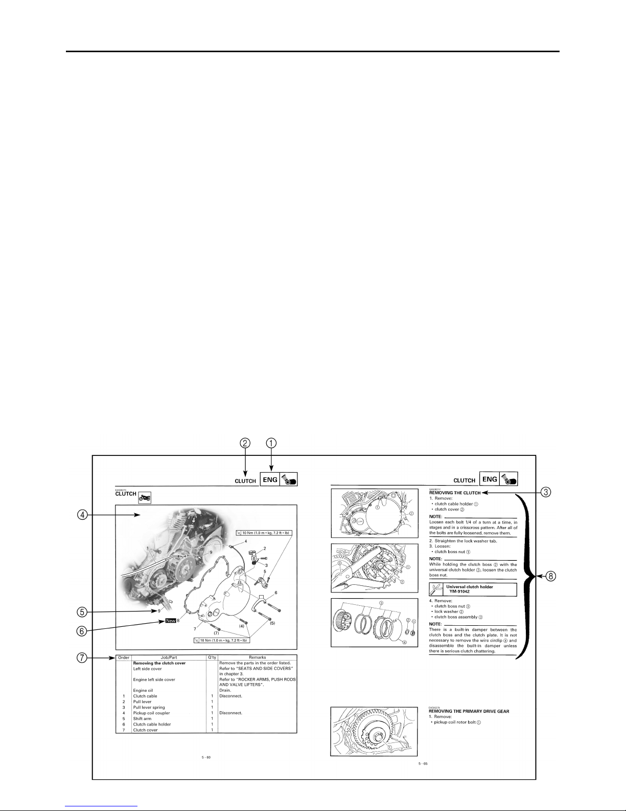
HOW TO USE THIS MANUAL
This manual is intended as a handy, easy-to-read reference book for the mechanic. Comprehensive
explanations of all installation, removal, disassembly, assembly, repair and check procedures are
laid out with the individual steps in sequential order.
1
The manual is divided into chapters. An abbreviation and symbol in the upper right corner of
each page indicate the current chapter.
Refer to “SYMBOLS”.
2
Each chapter is divided into sections. The current section title is shown at the top of each page,
except in Chapter 3 (“PERIODIC CHECKS AND ADJUSTMENTS”), where the sub section title(s)
appears.
3
Sub section titles appear in smaller print than the section title.
4
To help identify parts and clarify procedure steps, there are exploded diagrams at the start of
each removal and disassembly section.
5
Numbers are given in the order of the jobs in the exploded diagram. A circled number indicates a
disassembly step.
6
Symbols indicate parts to be lubricated or replaced.
Refer to “SYMBOLS”.
7
A job instruction chart accompanies the exploded diagram, providing the order of jobs, names of
parts, notes in jobs, etc.
8
Jobs requiring more information (such as special tools and technical data) are described sequentially.
12
GEN
SPEC
INFO
34
CHK
CHAS
ADJ
56
ENG
78
CARB
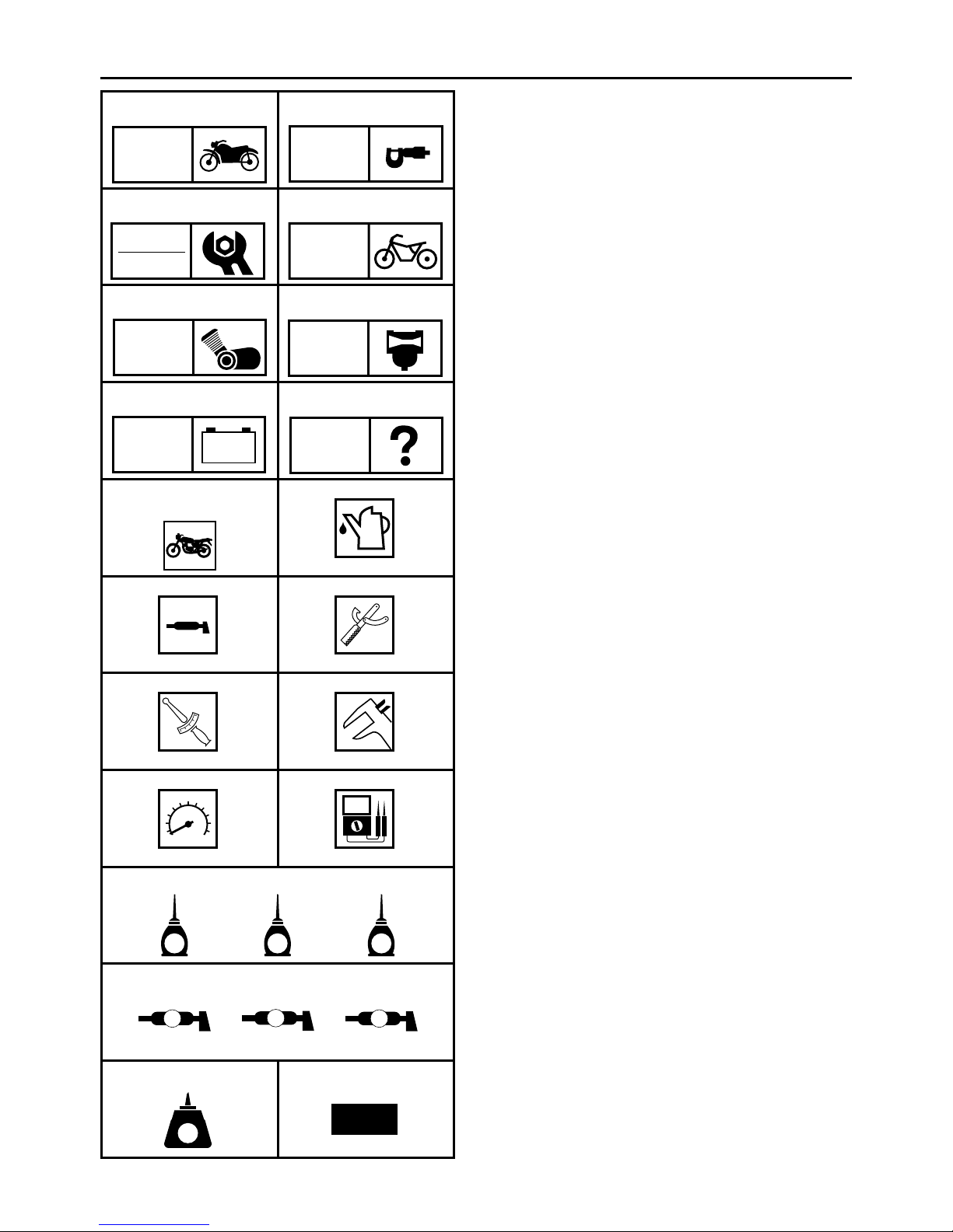
SYMBOLS
The following symbols are not relevant to
every vehicle.
Symbols 1 to 8 indicate the subject of each
chapter.
General information
1
Specifications
2
Periodic checks and adjustments
3
Chassis
4
Engine
5
Carburetor
6
Electrical system
7
Troubleshooting
8
–+
TRBL
ELEC
SHTG
90
AB
CD
T
.
R
.
EF
GHI
Symbols 9 to F indicate the following.
Serviceable with engine mounted
9
Filling fluid
0
Lubricant
A
Special tool
B
Tightening torque
C
Wear limit, clearance
D
Engine speed
E
Electrical data
F
Symbols G to L in the exploded diagrams
indicate the types of lubricants and lubrication
points.
E
JKL
B
MN
LT
G
LS
M
M
New
Engine oil
G
Gear oil
H
Molybdenum disulfide oil
I
Wheel bearing grease
J
Lithium-soap-based grease
K
Molybdenum disulfide grease
L
Symbols M to N in the exploded diagrams
indicate the following.
®
Apply locking agent (LOCTITE
M
Replace the part.
N
).

CONTENTS
SPECIFICATIONS
GENERAL SPECIFICATIONS ..................................................................1
ENGINE SPECIFICATIONS ......................................................................2
CHASSIS SPECIFICATIONS ....................................................................6
ELECTRICAL SPECIFICATIONS ...........................................................10
TIGHTENING TORQUES .......................................................................11
ENGINE TIGHTENING TORQUES ....................................................11
CHASSIS TIGHTENING TORQUES ..................................................12
CABLE ROUTING ...................................................................................13
PERIODIC CHECKS AND ADJUSTMENTS
INTRODUCTION .....................................................................................27
PERIODIC MAINTENANCE CHART FOR THE EMISSION CONTROL
SYSTEM ..................................................................................................27
GENERAL MAINTENANCE AND LUBRICATION CHART .....................27
SEATS AND SIDE COVERS ..................................................................30
FUEL TANK .............................................................................................31
CHASSIS
FRONT WHEEL AND BRAKE DISCS ....................................................32
REAR WHEEL, BRAKE DISC AND REAR WHEEL PULLEY .................33
FRONT AND REAR BRAKES .................................................................35
HANDLEBAR ..........................................................................................47
REAR SHOCK ABSORBER AND SWINGARM ......................................49
DRIVE BELT AND DRIVE PULLEY ........................................................53
........................................................................................................32
FRONT BRAKE PADS ........................................................................35
REPLACING THE FRONT BRAKE PADS ..........................................36
REAR BRAKE MASTER CYLINDER ..................................................38
FRONT BRAKE CALIPERS ................................................................40
DISASSEMBLING THE FRONT BRAKE CALIPERS .........................42
CHECKING THE FRONT BRAKE CALIPERS ....................................43
ASSEMBLING AND INSTALLING THE FRONT BRAKE
CALIPERS ..........................................................................................44
............................................................................................1
..................................................27
ENGINE
..........................................................................................................54
ROCKER ARMS, PUSH RODS AND VALVE LIFTERS .........................54
INSTALLING THE ROCKER ARMS AND PUSH RODS ....................57
INSTALLING THE CYLINDER HEAD COVERS .................................58
CLUTCH ..................................................................................................59
INSTALLING THE CLUTCH BOSS NUT ............................................61
GENERATOR AND STARTER CLUTCH ................................................62
CRANKSHAFT AND CONNECTING RODS ...........................................63
CHECKING THE CRANKSHAFT AND CONNECTING RODS ..........63
INSTALLING THE CONNECTING RODS ..........................................67
TRANSMISSION .....................................................................................70

CARBURETOR ...............................................................................................71
AIR INDUCTION SYSTEM ......................................................................71
AIR INDUCTION SYSTEM DIAGRAMS .............................................71
XV17AS(C)/XV17ASS(C)/XV17ATS(C) WIRING DIAGRAM
GENERAL SPECIFICATIONS
SPEC
SPECIFICATIONS
GENERAL SPECIFICATIONS
Item Standard Limit
Model code
Dimensions
Overall length 2,500 mm (98.4 in) ---Overall width 980 mm (38.6 in) ---Overall height 1,140 mm (44.9 in) (XV17A/XV17AS)
Seat height 710 mm (28.0 in) ---Wheelbase 1,688 mm (66.5 in) ---Minimum ground clearance 145 mm (5.71 in) ---Minimum turning radius 3,200 mm (126 in) ----
Weight
Wet (with oil and a full fuel tank) 334 kg (736 lb) (XV17A/XV17AS)
Dry (without oil and fuel) 312 kg (688 lb) (XV17A/XV17AS)
Maximum load (total of cargo, rider,
passenger, and accessories)
5VN1 (XV17A for USA)
5VN2 (XV17A for California)
5VN6 (XV17A for CDN)
5VR1 (XV17AS for USA)
5VR2 (XV17AS for California)
5VR3 (XV17AS for CDN)
5VP1 (XV17AT for USA)
5VP2 (XV17AT for California)
5VP3 (XV17AT for CDN)
5VP4 (XV17AT for Hawaii)
1,500 mm (59.1 in) (XV17AT)
349 kg (769 lb) (XV17AT)
327 kg (721 lb) (XV17AT)
194 kg (428 lb) (XV17A/XV17AS)
179 kg (395 lb) (XV17AT)
----
----
----
----
----
----
----
----
----
----
----
----
----
----
----
----
----
----
– 1 –

ENGINE SPECIFICATIONS
SPEC
ENGINE SPECIFICATIONS
Item Standard Limit
Engine
Engine type Air-cooled, 4-stroke, OHV ---Displacement 1,670 cm
Cylinder arrangement V-type 2-cylinder ---Bore × stroke 97 × 113 mm (3.82 × 4.45 in) ---Compression ratio 8.36 : 1 ---Engine idling speed 850 ~ 950 r/min ---Vacuum pressure at engine idling
speed
Standard compression pressure
(at sea level)
Camshafts
Drive system Gear drive ---Crankcase hole inside diameter 25.000 ~ 25.021 mm (0.9843 ~ 0.9851 in) ---Camshaft cover hole inside diameter 28.000 ~ 28.021 mm (1.1024 ~ 1.1032 in) ---Camshaft journal diameter
(crankcase side)
Camshaft journal diameter
(camshaft cover side)
Camshaft to crankcase clearance 0.050 ~ 0.084 mm (0.0020 ~ 0.0033 in) ---Camshaft to camshaft cover clear-
ance
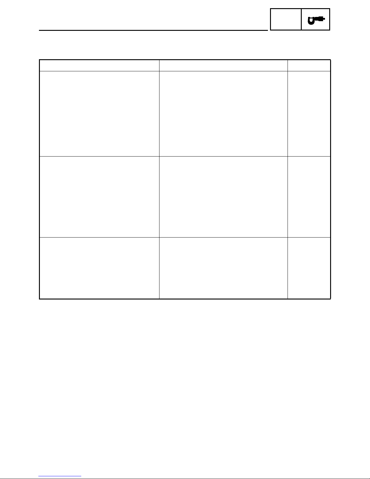
Camshaft intake cam dimensions
43.3 kPa (325 mm Hg, 12.8 in Hg) ----
1,200 kPa
(12.0 kgf/cm
24.937 ~ 24.950 mm (0.9818 ~ 0.9823 in) ----
27.967 ~ 27.980 mm (1.1011 ~ 1.1016 in) ----
0.020 ~ 0.054 mm (0.0008 ~ 0.0021 in) ----
3
2
, 171 psi) at 200 r/min
----
----
A
B
Measurement A (front cylinder) 38.242 ~ 38.342 mm (1.5056 ~ 1.5095 in) 38.142 mm
(1.5017 in)
(rear cylinder) 38.241 ~ 38.341 mm (1.5055 ~ 1.5095 in) 38.141 mm
(1.5016 in)
Measurement B 31.977 ~ 32.077 mm (1.2589 ~ 1.2629 in) 31.877 mm
(1.2550 in)
– 2 –
ENGINE SPECIFICATIONS
Item Standard Limit
Camshaft exhaust cam dimensions
A
B
Measurement A 38.236 ~ 38.336 mm (1.5054 ~ 1.5093 in) 38.136 mm
Measurement B 32.013 ~ 32.113 mm (1.2604 ~ 1.2643 in) 31.913 mm
Rocker arms, rocker arm shafts
Rocker arm inside diameter 18.000 ~ 18.018 mm (0.7087 ~ 0.7094 in) 18.036 mm
Rocker arm shaft outside diameter 17.976 ~ 17.991 mm (0.7077 ~ 0.7083 in) ---Rocker arm to rocker arm shaft clear-
ance
Valve lifters
Valve lifter outside diameter 22.962 ~ 22.974 mm (0.9040 ~ 0.9045 in) ---Valve lifter case inside diameter 23.000 ~ 23.021 mm (0.9055 ~ 0.9063 in) ---Valve lifter-to-valve lifter case clear-
ance
Valve push rods
Valve push rod length 1 288.25 ~ 288.75 mm (11.348 ~ 11.368 in) ---Valve push rod length 2 290.25 ~ 290.75 mm (11.427 ~ 11.447 in) ---Valve push rod runout 0.3 mm (0.012 in) ----
Cylinders
Bore 97.000 ~ 97.010 mm (3.8189 ~ 3.8193 in) ---Maximum taper ---- 0.05 mm
Maximum out of round ---- 0.05 mm
0.009 ~ 0.042 mm (0.0004 ~ 0.0017 in) 0.08 mm
0.026 ~ 0.059 mm (0.0010 ~ 0.0023 in) ----
SPEC
(1.5014 in)
(1.2564 in)
(0.7101 in)
(0.003 in)
(0.0016 in)
(0.0016 in)
– 3 –
ENGINE SPECIFICATIONS
Item Standard Limit
Pistons
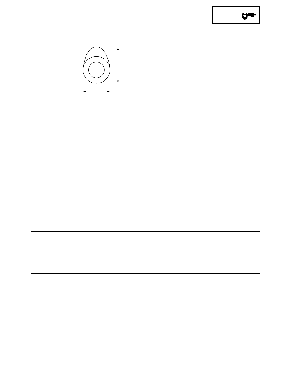
Piston-to-cylinder clearance 0.025 ~ 0.050 mm (0.001 ~ 0.002 in) 0.15 mm
Diameter D 96.960 ~ 96.975 mm (3.8173 ~ 3.8179 in) ----
H
D
Height H 5 mm (0.20 in) ---Piston pin bore (in the piston)
Diameter 22.004 ~ 22.015 mm (0.8663 ~ 0.8667 in) 22.045 mm
Offset 1.0 mm (0.04 in) ----
Piston pins
Outside diameter 21.991 ~ 22.000 mm (0.8658 ~ 0.8661 in) 21.971 mm
Piston pin-to-piston pin bore clearance
Piston rings
Top ring
0.004 ~ 0.024 mm (0.00016 ~ 0.00094 in) 0.074 mm
SPEC
(0.006 in)
(0.8679 in)
(0.8650 in)
(0.0029 in)
B
T
Ring type Barrel ---Dimensions (B × T) 1.2 × 3.8 mm (0.047 × 0.150 in) ---End gap (installed) 0.30 ~ 0.45 mm (0.012 ~ 0.018 in) 0.65 mm
(0.026 in)
Ring side clearance 0.03 ~ 0.08 mm (0.0012 ~ 0.0031 in) 0.12 mm
(0.0047 in)
2nd ring
B
T
Ring type Taper ---Dimensions (B × T) 1.2 × 3.8 mm (0.047 × 0.150 in) ---End gap (installed) 0.30 ~ 0.45 mm (0.012 ~ 0.018 in) 0.8 mm
(0.031 in)
Ring side clearance 0.03 ~ 0.07 mm (0.0012 ~ 0.0028 in) 0.12 mm
(0.0047 in)
Oil ring
B
Dimensions (B × T) 2.5 × 3.4 mm (0.098 × 0.134 in) ---End gap (installed) 0.2 ~ 0.7 mm (0.008 ~ 0.028 in) ----
T
– 4 –
ENGINE SPECIFICATIONS
Item Standard Limit
Transmission
Transmission type Constant mesh, 5-speed ---Primary reduction system Spur gear ---Primary reduction ratio 72/47 (1.532) ---Secondary reduction system Belt drive ---Secondary reduction ratio 35/32 × 70/32 (2.393) ---Operation Left-foot operation ---Gear ratios
1st gear 38/16 (2.375) ---2nd gear 30/19 (1.579) ---3rd gear 29/25 (1.160) ---4th gear 29/32 (0.906) ---5th gear 21/28 (0.750) ----
Maximum main axle runout ---- 0.08 mm
Maximum drive axle runout ---- 0.08 mm
Fuel pump
Pump type Electrical ---Model (manufacturer) UC-Z10C (MITSUBISHI) ---Output pressure 15 ~ 20 kPa
(0.15 ~ 0.20 kgf/cm
Carburetor
Model (manufacturer) × quantity BSR40 (MIKUNI) × 1 ---Throttle cable free play (at the flange
of the throttle grip)
ID mark 5VN1 00
Main jet #182.5 ---Main air jet #60 ---Jet needle 6HDC26-1 ---Needle jet X-2M ---Pilot air jet 1 #100 ---Pilot air jet 2 2.0 ---Pilot outlet 1.1 ---Pilot jet #35 ---Bypass 1 0.9 ---Bypass 2 1.0 ---Bypass 3 0.9 ---Valve seat size 2.0 ---Starter jet 1 0.65 ---Starter jet 2 0.7 ---Butterfly valve size #110 ---Fuel level (above the float chamber
mating surface)
4 ~ 6 mm (0.16 ~ 0.24 in) ----
5VN2 10 (for California)
4.0 ~ 5.0 mm (0.16 ~ 0.20 in) ----
2
, 2.13 ~ 2.84 psi)
SPEC
(0.003 in)
(0.003 in)
----
----
----
– 5 –
CHASSIS SPECIFICATIONS
SPEC
CHASSIS SPECIFICATIONS
Item Standard Limit
Front wheel
Wheel type Cast wheel
Spoke wheel (XV17A for CDN)
Rim
Size 16M/C × MT3.00 ----
Material Aluminum
Steel (XV17A for CDN)
Wheel travel 140 mm (5.51 in) ---Wheel runout
Maximum radial wheel runout ----
----
Maximum lateral wheel runout ----
----
Rear wheel
Wheel type Cast wheel
Spoke wheel (XV17A for CDN)
Rim
Size 16M/C × MT3.50 ----
Material Aluminum
Steel (XV17A for CDN)
Wheel travel 110 mm (4.33 in) ---Wheel runout
Maximum radial wheel runout ----
----
Maximum lateral wheel runout ----
----
1 mm
(0.04 in)
2 mm
(0.08 in)
(XV17A for
CDN)
0.5 mm
(0.02 in)
2 mm
(0.08 in)
(XV17A for
CDN)
1 mm
(0.04 in)
2 mm
(0.08 in)
(XV17A for
CDN)
0.5 mm
(0.02 in)
2 mm
(0.08 in)
(XV17A for
CDN)
----
----
----
----
----
----
----
----
– 6 –
CHASSIS SPECIFICATIONS
SPEC
Item Standard Limit
Front tire
Tire type Tubeless
With tube (XV17A for CDN)
Size 130/90–16M/C 67H ---Model (manufacturer) USA CDN
G703 N
(BRIDGESTONE)
(XV17A/XV17AS)
G703
(BRIDGESTONE)
(XV17AT)
G703 F
(BRIDGESTONE)
(XV17A)
D404FL
(DUNLOP)
(XV17A)
G703 N
(BRIDGESTONE)
(XV17AS)
G703
(BRIDGESTONE)
(XV17AT)
Tire pressure (cold)
0 ~ 90 kg (0 ~ 198 lb) 250 kPa (2.5 kg/cm
90 kg (198 lb) ~ Maximum load* 250 kPa (2.5 kg/cm
High-speed riding 250 kPa (2.5 kg/cm
2
, 36 psi) ----
2
, 36 psi) ----
2
, 36 psi) ---* Load is the total weight of the cargo,
rider, passenger and accessories.
Minimum tire tread depth ---- 1.0 mm
(0.04 in)
Rear tire
Tire type Tubeless
With tube (XV17A for CDN)
Size 150/80B16M/C 71H ---Model (manufacturer) USA CDN
G702 N
(BRIDGESTONE)
(XV17A/XV17AS)
G702
(BRIDGESTONE)
(XV17AT)
G702
(BRIDGESTONE)
(XV17A/XV17AT)
D404
(DUNLOP)
(XV17A)
G702 N
(BRIDGESTONE)
(XV17AS)
Tire pressure (cold)
0 ~ 90 kg (0 ~ 198 lb) 250 kPa (2.5 kg/cm
90 kg (198 lb) ~ Maximum load* 280 kPa (2.8 kg/cm
High-speed riding 280 kPa (2.8 kg/cm
2
, 36 psi) ----
2
, 41 psi) ----
2
, 41 psi) ----
* Load is the total weight of the cargo,
rider, passenger and accessories.
Minimum tire tread depth ---- 1.0 mm
(0.04 in)
----
----
----
----
----
----
----
----
----
----
----
– 7 –
CHASSIS SPECIFICATIONS
Item Standard Limit
Front brakes
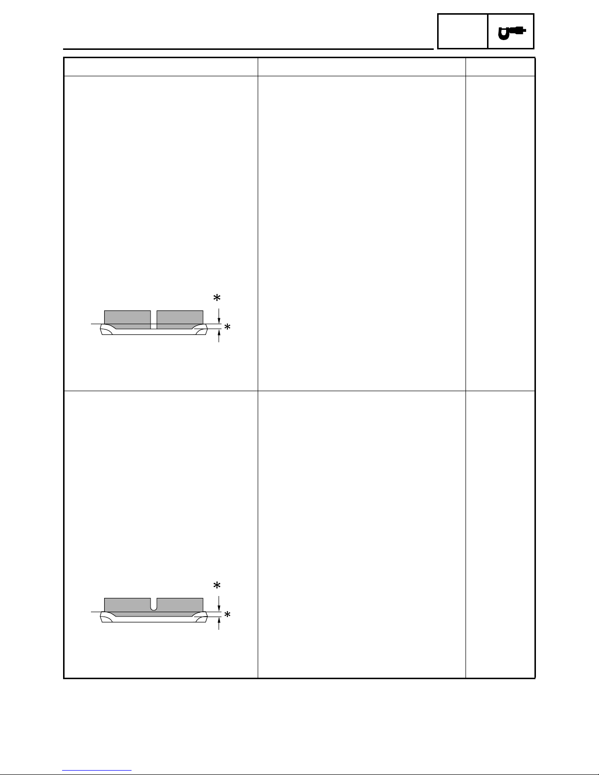
Brake type Dual-disc brake ---Operation Right-hand operation ---Brake lever free play (lever end) 2 ~ 5 mm (0.08 ~ 0.20 in) ---Recommended fluid DOT 4 ---Brake discs
Diameter × thickness 298 × 5 mm (11.7 × 0.20 in) ---Minimum thickness ---- 4.5 mm
Maximum deflection ----
----
Brake pad lining thickness 5.5 mm (0.22 in) 0.5 mm
SPEC
(0.18 in)
0.1 mm
(0.004 in)
0.15 mm
(0.006 in)
(XV17A for
CDN)
(0.02 in)
Master cylinder inside diameter 14.0 mm (0.55 in) ---Caliper cylinder inside diameter 27.00 mm (1.06 in) and
30.20 mm (1.19 in)
Rear brake
Brake type Single-disc brake ---Operation Right-foot operation ---Brake pedal position (from the top of
the brake pedal to the bottom of the
rider footrest board)
Recommended fluid DOT 4 ---Brake discs
Diameter × thickness 320 × 7 mm (12.6 × 0.28 in) ---Minimum thickness ---- 6.5 mm
Maximum deflection ---- 0.15 mm
Brake pad lining thickness 7.0 mm (0.28 in) 0.5 mm
100 mm (3.9 in) ----
(0.26 in)
(0.006 in)
(0.02 in)
----
Master cylinder inside diameter 12.7 mm (0.5 in) ---Caliper cylinder inside diameter 33.96 mm (1.34 in) and
----
30.23 mm (1.19 in)
– 8 –

CHASSIS SPECIFICATIONS
Item Standard Limit
Drive belt
Model (manufacturer) UBD-0681 ---Drive belt slack (on a sidestand) 6 ~ 8 mm (0.24 ~ 0.31 in) ---Drive belt slack (on a suitable stand) 7 ~ 9 mm (0.28 ~ 0.35 in) ----
SPEC
– 9 –
ELECTRICAL SPECIFICATIONS
SPEC
ELECTRICAL SPECIFICATIONS
Item Standard Limit
System voltage
Ignition system
Ignition system type Transistorized coil ignition (digital) ---Ignition timing 10° BTDC at 900 r/min ---Advancer type Throttle position sensor and electrical ---Pickup coil resistance/color 248 ~ 372 Ω/Gy—B ----
Transistorized coil ignition unit model
(manufacturer)
Ignition coils
Model (manufacturer) JO447 (DENSO) ---Minimum ignition spark gap 6 mm (0.24 in) ---Primary coil resistance 1.32 ~ 1.78 Ω ----
Secondary coil resistance 12 ~ 18 kΩ ----
Bulbs (voltage/wattage × quantity)
Headlight 12 V 60 W/55 W × 1 ---Tail/brake light LED ---Front turn signal/position light 12 V 23 W/8 W × 2 ---Rear turn signal light 12 V 21 W × 2 ---Licence plate light 12 V 5 W × 1 ---Meter light 14 V 0.56 W × 4 ---Neutral indicator light 14 V 1.12 W × 1 ---Turn signal indicator light 14 V 1.12 W × 1 ---High beam indicator light 14 V 1.12 W × 1 ---Fuel level indicator light LED ---Engine trouble indicator light LED ----
Turn signal relay
Relay type Semi-transistor ---Model (manufacturer) FB257H (DENSO) ---Self-cancelling device built-in Yes ---Turn signal blinking frequency 75 ~ 95 cycles/min. ---Wattage 23 W × 2 + 3.4 W ----
Fuel sender
Model (manufacturer) 5VN (NIPPON SEIKI) ---Resistance 13 ~ 140 Ω at 20 °C (68 °F) ----
Sidestand relay
Model (manufacturer) G8R-30Y-X (OMRON) ---Coil resistance 162 ~ 198 Ω ----
Fuel pump relay model
(manufacturer)
Thermo switch model
(manufacturer)
12 V ----
J4T139 (MITSUBISHI) ----
G8R-30Y-X (OMRON) ----
5FU (NIPPON THERMOSTAT) ----
– 10 –
TIGHTENING TORQUES
ENGINE TIGHTENING TORQUES
TIGHTENING TORQUES
SPEC
Item Fastener
Thread
size
Tightening torque
Q’ty
Nm m · kgf ft · lb
Remarks
Cylinder head Nut M12 8 60 6.0 43
Rocker arm base Bolt M8 4 24 2.4 17
Rocker arm base Bolt M6 8 10 1.0 7.2
Front cylinder camshaft end cover Bolt M5 2 7 0.7 5.1
Carburetor joint clamp Screw M4 1 4 0.4 2.9
Exhaust pipe Nut M8 4 20 2.0 14
Muffler Bolt M10 2 35 3.5 25
Muffler clamp Bolt M8 2 20 2.0 14
Generator rotor Bolt M12 1 80 8.0 58
Pickup coil rotor Bolt M12 1 100 10.0 72
Clutch boss Nut M20 1 105 10.5 75 Stake
Pull lever Bolt M6 1 12 1.2 8.7
Middle drive gear Nut M22 1 100 10.0 72
Use a lock
washer.
Drive pulley case Bolt M10 3 50 5.0 36
Drive pulley case Bolt M8 4 30 3.0 22
Drive pulley Nut M22 1 100 10.0 72
Use a lock
washer.
Shift arm Bolt M6 2 14 1.4 10
Neutral switch Screw M6 2 4 0.4 2.9
LT
LT
E
– 11 –
CHASSIS TIGHTENING TORQUES
TIGHTENING TORQUES
SPEC
Item Thread size
Upper bracket and inner tube M6 18 1.8 13
Handlebar holder (lower) and handlebar holder
(upper)
Throttle cable adjusting nut and locknut M6 4 0.4 2.9
Engine mounting:
Lower front mounting bolt M12 103 10.3 74
Lower rear mounting bolt M12 88 8.8 64
Transfer gear case stay and frame M10 72 7.2 52
Muffler stay and frame M10 53 5.3 38
Fuel sender and fuel tank M6 8 0.8 5.8
Rear fender side mold and rear fender stay M8 28 2.8 20
Sidestand bolt M10 89 8.9 64
Sidestand nut M10 32 3.2 23
Rear brake fluid reservoir M6 9 0.9 6.5
Grip end M16 23 2.3 17
M8 28 2.8 20
Tightening torque
Nm m · kgf ft · lb
Remarks
– 12 –
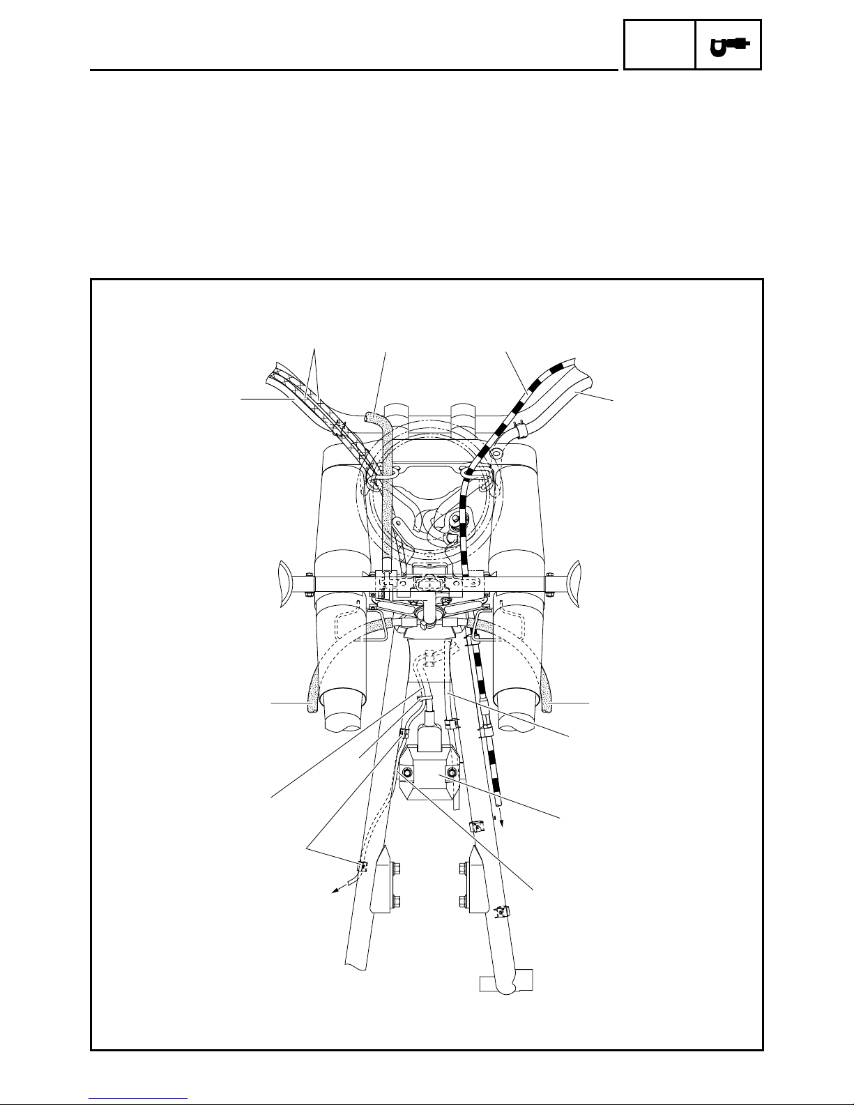
EB206000
CABLE ROUTING
Right handlebar switch lead
1
Throttle cables
2
Brake hoses
3
Clutch cable
4
Left handlebar switch lead
5
Air induction system vacuum hose
6
Rectifier/regulator
7
Rear brake light switch lead
8
CABLE ROUTING
To engine
È
Route the rear brake light switch lead in front of
É
the rectifier/regulator bracket on the frame.
To rear brake light switch
Ê
Fasten the rear brake light switch lead with the
Ë
plastic holder.
Fasten the rear brake light switch lead and recti-
Ì
fier/regulator lead with the plastic locking tie.
SPEC
1
3
2
3
4
5
3
6
8
Ë
Ê
Ì
– 13 –
È
É
7

CABLE ROUTING
SPEC
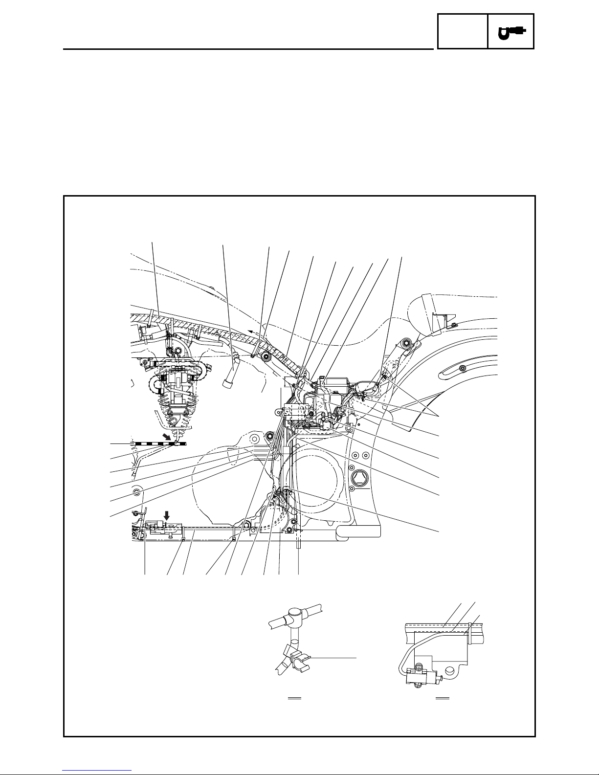
1 Rectifier/regulator lead
2 Rear brake light switch lead
3 Wire harness
4 Seat lock cable
5 Throttle position sensor coupler
6 Carburetor heater coupler
7 Air induction system vacuum hose
8 Fuel pump lead
9 Spark plug cap #1
0 Spark plug cap #3
A Horn
É
3
È
B Horn lead
C Starter motor lead
D Clutch cable
Ê
4
Ë
Ì
Í
5
6
Î
Ï
7
8
9
2
1
5
6
Ò
È
8
Ò
D
Ö
B
A
Ó
Ô
Ñ
C
Ñ
Ð
B
A
0
Õ
A
B
– 14 –

CABLE ROUTING
SPEC
È Fasten the rectifier/regulator lead and rear brake
light switch lead with the plastic holders.
É Pass the left handlebar switch lead through the
left brake hose guide and the right handlebar
switch lead through the right brake hose guide
under the upper bracket.
Ê Fasten the wire harness with the plastic holder.
Ë Fasten the wire harness and seat lock cable to
the frame with the plastic band.
É
3
È
Ì Fasten the air induction system vacuum hose
and spark plug lead #2 with the plastic holder.
Í Fasten the wire harness, seat lock cable, spark
plug lead #1, and spark plug lead #2 to the
engine bracket with the plastic band.
Î Fasten the spark plug lead #1 and spark plug
lead #2 with the plastic holder.
Ï Fasten the wire harness, seat lock cable, and
spark plug lead #1 with the plastic band.
Ê
4
Ë
Ì
Í
5
6
Î
Ï
7
8
9
2
1
5
6
Ò
È
8
Ò
D
Ö
B
A
Ó
Ô
Ñ
C
Ñ
Ð
B
A
0
Õ
A
B
– 15 –
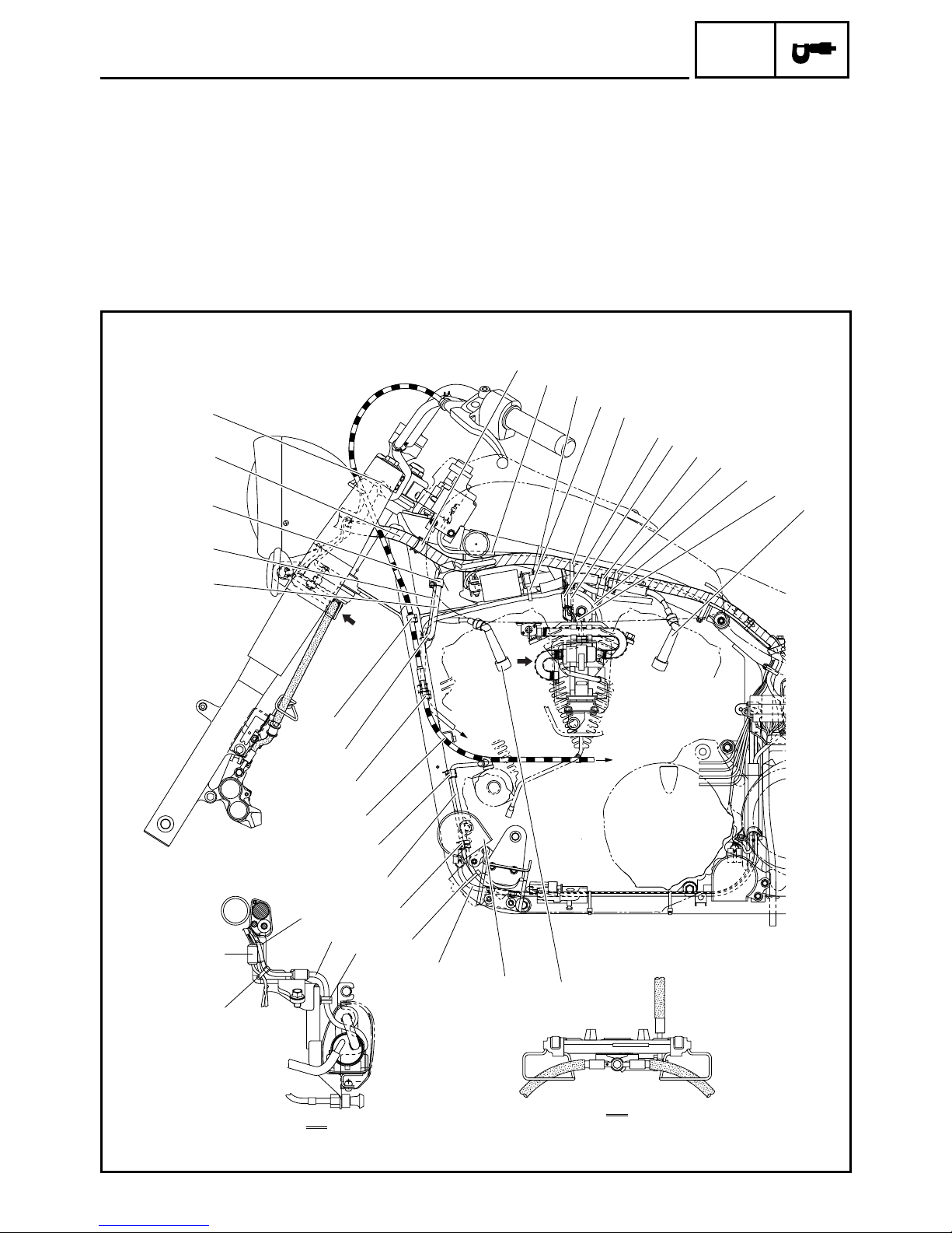
CABLE ROUTING
SPEC
Ð Fasten the horn lead and starter motor lead to
the frame with the plastic locking tie.
Ñ Fasten the starter motor lead with the plastic
holders.
Ò Fasten the clutch cable with the plastic holders.
Ó To air cut-off valve
Ô To engine
Õ Fasten the throttle position sensor lead, carbure-
tor heater lead, and fuel pump lead to the fuel
pump bracket with the plastic locking tie.
É
3
È
Ö Fasten the fuel pump lead with the plastic
holder.
Ê
4
Ë
Ì
Í
5
6
Î
Ï
7
8
9
2
1
5
6
Ò
È
8
Ò
D
Ö
B
A
Ó
Ô
Ñ
C
Ñ
Ð
B
A
0
Õ
A
B
– 16 –

CABLE ROUTING
SPEC
1 Wire harness
2 Spark plug cap #1
3 Fuel sender lead
4 Negative battery lead
5 Positive battery lead
6 Tail/brake light lead
7 Starter relay
8 Thermo switch
9 Starter motor lead
0 Fuel tank breather hose
A Horn
1
2
È
É
B Pickup coil lead
C Sidestand switch lead
D Horn lead
E Decompression solenoid lead
F Stator coil lead
G Neutral switch lead
H Speed sensor lead
I Clutch cable
3
3
Ê
Ë
Ì
4
5
6
I
Ô
H
G
F
E
Í
A
B
DC B A0
ÓÓÒ
Ñ
Õ
Î
Ï
7
8
9
Ð
9
D
C
A B
– 17 –
CABLE ROUTING
SPEC
È To fuel sender
É Fasten the wire harness and seat lock cable to
the frame with the plastic band.
Ê Fasten the wire harness, fuel sender lead and
seat lock cable with the plastic locking tie.
Ë Fasten the wire harness and all leads that
branch off from the wire harness with the plastic
band.
Ì Fasten the wire harness and negative battery
lead with the plastic holder.
1
2
É
È
Í 25 ~ 35 mm (0.98 ~ 1.38 in)
Î Fasten the tail/brake light lead with the plastic
holders.
Ï Pass the positive battery lead through the hole in
the battery box.
Ð Fasten the sidestand switch lead, horn lead,
starter motor lead, and pickup coil lead with the
plastic holder.
Ñ Fasten the pickup coil lead with the metal holder.
3
3
Ê
Ë
Ì
4
5
6
I
Ô
H
G
F
E
Í
A
B
DC B A0
ÓÓÒ
Ñ
Õ
Î
Ï
7
8
9
Ð
9
D
C
A B
– 18 –
 Loading...