

Yamaha WR450F 2-TRAC, WR450FS 2-TRAC Supplementary Owner's Service Manual

WR450F(S) 2-TRAC
SUPPLEMENTARY
OWNER’S SERVICE MANUAL
5TJ-F8199-E0

WR450F(S) 2-TRAC
SUPPLEMENTARY
OWNER’S SERVICE MANUAL
© 2004 by Yamaha Motor Italia S.p.A.
First edition, March 2004
All rights reserved. Any reproduction or
unauthorized use without the written
permission of Yamaha Motor Italia S.p.A.
is expressly prohibited.
Printed in Italy

1
CONTENTS
HYDROSTATIC TRANSMISSION .......................................................................................... 2
WHEN DRIVING.............................................................................................................. 2
FUNCTION ...................................................................................................................... 2
ADJUSTMENTS .............................................................................................................. 3
ALTERNATE RATIOS (OPTIONS) .................................................................................. 3
TOOLS ............................................................................................................................ 3
SPECIAL TOOLS .................................................................................................................. 4
SPECIFICATIONS .................................................................................................................. 6
GENERAL SPECIFICATIONS ........................................................................................ 6
MAINTENANCE SPECIFICATIONS ...................................................................................... 7
CHASSIS ........................................................................................................................ 7
TIGHTENING TORQUES ................................................................................................ 8
CABLE ROUTING DIAGRAM.......................................................................................... 9
REGULAR INSPECTION AND ADJUSTMENTS..................................................................17
MAINTENANCE INTERVALS ........................................................................................ 17
SUPPLEMENT ARY INSPECTION AND ADJUSTMENTS ............................................ 17
HYDROSTATIC TRANSMISSION.................................................................................. 17
STEERING DAMPER ADJUSTMENT .......................................................................... 18
FRONT FORK REBOUND DAMPING FORCE ADJUSTMENT.................................... 21
FRONT FORK COMPRESSION DAMPING FORCE ADJUSTMENT .......................... 22
REAR SHOCK ABSORBER SPRING PRELOAD ADJUSTMENT................................ 23
REAR SHOCK ABSORBER REBOUND DAMPING FORCE ADJUSTMENT .............. 24
REAR SHOCK ABSORBER LOW COMPRESSION DAMPING FORCE
ADJUSTMENT .............................................................................................................. 25
REAR SHOCK ABSORBER HIGH COMPRESSION DAMPING FORCE
ADJUSTMENT .............................................................................................................. 26
CARBURETOR DISASSEMBLY .......................................................................................... 27
TRANSMISSION .................................................................................................................. 28
DRIVE UNIT – TRANSMISSION ASSY ........................................................................ 28
HYDROSTATIC TRANSMISSION.................................................................................. 30
INSPECTION ................................................................................................................ 30
CHANGE OIL IN THE HYDRAULIC MOTOR REDUCTION GEAR HOUSING............ 30
CHANGE OIL IN THE PUMP TRANSMISSION HOUSING .......................................... 31
CHECK THE WEAR IN THE PUMP TRANSMISSION.................................................. 32
CHANGING THE RATIOS FOR THE PUMP TRANSMISSION .................................... 33
FRONT WHEEL .................................................................................................................... 35
FRONT WHEEL REMOVAL .......................................................................................... 35
FRONT FORK ...................................................................................................................... 36
FRONT FORK DISASSEMBLY...................................................................................... 36
FRONT FORK SPECIFICATION CARD – ÖHLINS®.................................................... 38
OIL LEVEL ADJUSTMENT ............................................................................................ 39
CHANGING SPRINGS .................................................................................................. 40
DISMANTLING .............................................................................................................. 42
ASSEMBLING................................................................................................................ 45
REAR SHOCK ABSORBER ................................................................................................ 48
REAR SHOCK ABSORBER DISASSEMBLY................................................................ 48
INSPECTION AND MAINTENANCE.............................................................................. 49
STEERING DAMPER .......................................................................................................... 50
DISASSEMBLY AND INSPECTION .............................................................................. 51

2
HYDROSTATIC TRANSMISSION
WHEN DRIVING
Driving a two wheel driven motorcycle is different from driving a conventional motorcycle. The front wheel
drive system, during certain conditions, affects the feeling of the handlebar. In sand, mud and snow the
traction is greatly improved. However in conditions with deep ruts and slippery surfaces the two wheel
drive system might contribute to that the motorcycle feels heavier and more brutal.
WARNING
It is of absolute necessity that the two wheel drive motorcycle has a steering damper. If driven
without steering damper the front wheel, when hitting a root or a stone, can give unduly high
reaction forces to the handlebar.
Before racing, practise as much as possible on different tracks and under different conditions to
get used to the different behaviour of the two wheel drive system.
On rough road surfaces the front wheel drive can make the steering harder. This is noticeable,
especially when driving aggressively.
When landing after jumps the two wheel drive system will make the front fork feel stiffer due to
that the driving force tries to extend the front fork, especially if the throttle is applied before
touchdown.
NOTE:
This 2-Trac system has been tested extensively on both test tracks and in races. Imperative for the durability and function is high quality material in all components. The high quality materials used are not
always the best suited to provide beautiful surface treatment. As a result we can sometimes see shades
and/or mis-colouring on the anodised aluminium surfaces.
FUNCTION
With the motorcycle free rolling, the pump rotates roughly with the same speed as the
motor.
When throttle is applied the rear wheel and thereby the pump, due to deformation of the
rear tire, starts to rotate a little bit faster even if the driving force is just large enough to
maintain constant speed.
The increased volume stream from the pump causes the speed of the motor to increase,
but to a lesser extent than the pump, thereby creating a driving torque from the front
wheel. Thus the amount of front wheel driving force varies with speed and ground condition and comes in gradually depending on throttle position.
The system has a maximum pressure relieve valve installed to prevent dangerously high
pressure in the system, when for instance on slippery surfaces, where excessive rear
wheel spin can occur.
The oil in the transmission can sometimes get very hot. For instance in sandy, slow
speed conditions or when trying to escape from a mud pit. In order to prevent damage to
the transmission a built in thermostat valve shortcuts the hydraulic circuit, thereby disconnecting the front wheel drive. When this occur a couple of minutes cooling time is needed
to get the system back into function again.
CAUTION:
3
ADJUSTMENTS
The pulling force, at a given circumstance, can be varied by changing the rear wheel
sprocket up or down one tooth. If we increase the no by one tooth the pump rotates
faster in relation to the hydraulic motor, thereby increasing the pressure in the system
and increasing the pulling force of the front wheel. It must be understood that even the
reaction forces in the handlebar increases. From experience the gain is negligible.
When decreasing with one/two/three teeth the pulling force is reduced. The advantage is
that the steering feels lighter and, on most ground conditions, there is no increased lap
times, but can be preferable during long endurance races.
WARNING
Changing the number of teeth of the sprockets more than one tooth up causes unduly high reaction forces in the handlebar. It can also give permanent damages to the hydraulic transmission
because of raised oil temperature in the transmission and increased wear.
Changing the number of teeth in the pump transmission without changing the rear-wheel
ratio also can cause permanent damage to the hydraulic transmission.
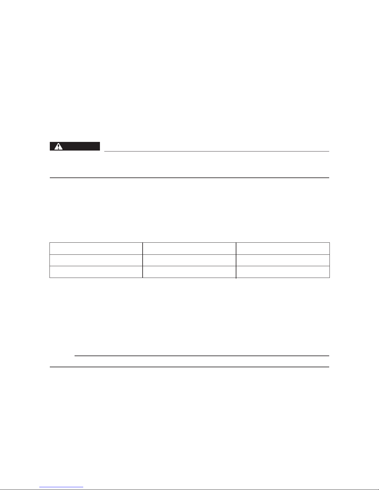
ALTERNATE RATIOS (OPTIONS)
There are alternate ratios for the pump transmission.
Alternate ratios kit Pump transmission ratio Rear wheel ratio
GTYA E00 15/22 standard 14/50
GTYA E01 12/20 P-D 15/47
The kit contains:
– Chain-sprocket pump
– Chain-wheel pump
– Chain
– Chain guide
– Collar
– Screw chain-sprocket
NOTE:
More ratios will be available later.
TOOLS
A specially designed puller tool is demanded to remove the pump sprocket. Refer to
“SPECIAL TOOLS”.
4
GEN
INFO
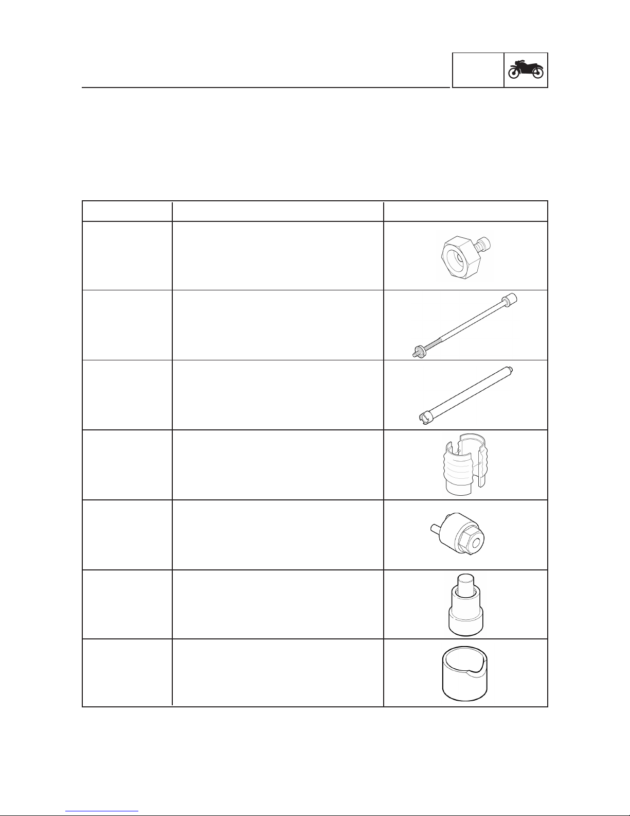
SPECIAL TOOLS
SPECIAL TOOLS
The following special tools are necessary for complete and accurate tune-up and assembly . Use only the
appropriate special tools; this will help prevent damage caused by the use of inappropriate tools or
improvised techniques. Special tools may differ by shape and part number from country to country. In
such a case, two types are provided.
When placing an order, refer to the list provided below to avoid any mistakes.
Tool No.
90890-XXXXX
(1702-02)
Bushing remover
Use this tool to remove the front forks bushing.
90890-XXXXX
(1797-01)
Tool cartridge top cap
Use this tool to remove and install the front
forks damper rod.
Tool name/How to use Illustration
90890-XXXXX
(1874-01)
Puller
Use this tool to remove the pump sprocket
(hydraulic transmission).
90890-XXXXX
(1799-02)
Mounting sleeve
Use this tool to install the front forks bushing
and seals.
90890-XXXXX
(1860-01)
Tool compression adjuster (Bob)
Use this tool to unscrew and screw the front
forks top cap.
90890-XXXXX
(0721-01)
Mandrel ball joints (26 mm)
This tool is needed to remove and install the
ball joints.
90890-XXXXX
(0723-01)
Sleeve (26 mm)
This tool is needed to remove and install the
ball joints with the mandrel.
5
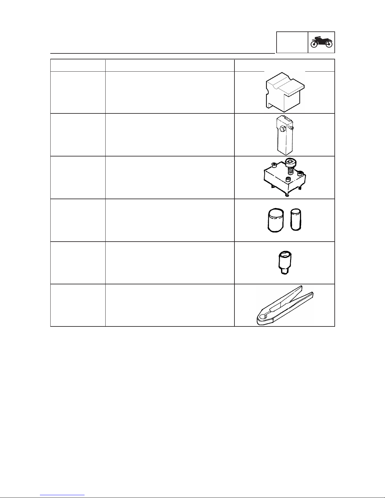
Tool No.
90890-XXXXX
(0727-03)
Soft jaws
Use this tool for piston shafts 14-16 mm.
Tool name/How to use Illustration
90890-XXXXX
(04957-01)
Steering damper holder
Use this tool for holding the steering damper
unit with or without link arm.
90890-XXXXX
(04954-01)
Puller
Use this tool for demounting the steering
damper linkarm.
90890-XXXXX
(04955-01)
90890-XXXXX
(04956-01)
Sockets
Use this tools for mounting the steering
damper linkarm.
90890-XXXXX
(04951-01)
Mandrel
Use this tool to install the steering damper
X-ring seal.
90890-XXXXX
(04960-01)
Holder
This tool is used for gripping the steering
damper high speed adjuster.
GEN
INFO
SPECIAL TOOLS

GENERAL SPECIFICATIONS
6
SPEC
SPECIFICATIONS
GENERAL SPECIFICATIONS
Item Standard
Model name: WR450F ’04 – 2-TRAC (EUROPE)
Model code number: 5TJ6 (EUROPE)
Dimensions:
Overall length 2,171 mm (85.5 in)
Overall width 827 mm (32.6 in)
Overall height 1,303 mm (51.3 in)
Seat height 998 mm (39.3 in)
Wheelbase 1,485 mm (58.5 in)
Minimum ground clearance 371 mm (14.6 in)
Dry weight:
Without oil and fuel 128.0 kg (282 lb)
Tire:
Type With tube
Size (front) 90/90-21 54R (EUROPE, AUS, NZ)
Size (rear) 130/90-18 69R (EUROPE, AUS, NZ)
Tire pressure (front) 100~120 kpa (1.0~1.2 kgf/cm
2
, 15~17 psi)
(depending on the track condition)
Tire pressure (rear) 100 kPa (1.0 kgf/cm2, 15 psi)
Suspension:
Front suspension Telescopic fork
Rear suspension Swingarm (link type monocross suspension)
Shock absorber:
Front shock absorber Coil spring/oil damper
Rear shock absorber Coil spring/gas, oil damper
Wheel travel:
Front wheel travel 300 mm (11.8 in)
Rear wheel travel 315 mm (12.4 in)
Hydrostatic transmission:
Pump/Motor:
Displacement of pump/motor 5 cm
3
per revolution
Max speed 8,000 rpm
Max torque 25 Nm
Max pressure 320 bar
Typical pressure 50-200 bar
Transmission:
Transmitted power, maximum 21 kW
Weight 6.7 kg
Efficiency 92 %
Oil volume 0.6 L
Ratio hydraulic motor/front wheel 5.36 : 1
Torque distribution 0-15 % on front wheel – depending
on ground condition and throttle position
Max pulling force on front wheel 382 N
Oil capacity:
Pump transmission housing 0.07-0.08 L
Hydraulic motor reduction gear housing 0.075 L
Oil type:
Pump transmission housing Castrol SLX030
Hydraulic motor reduction gear housing Castrol SLX030

SPEC
MAINTENANCE SPECIFICATIONS
7
MAINTENANCE SPECIFICATIONS
CHASSIS
Item Standard Limit
Front suspension:
Shock absorber travel 300 mm •••
Fork spring free length 467 mm 460 mm
Installed length 463 mm (4 mm preload) •••
Collar length – •••
Spring rate (K1) 4.5 N/mm (Left leg), 4.1 N/mm (Right leg) •••
Spring rate (K2) 10 N/mm (Top out spring) •••
Spring stroke (K1) 300 mm •••
Spring stroke (K2) 25 mm (approximately) •••
Optional spring available Yes •••
Quantity 625 cm
2
(approximately) •••
Level 105 mm •••
Recommended oil Öhlins part no: 1305-01 (SAE 5W) •••
Inner tube outer diameter 46 mm •••
Rear suspension:
Rear shock absorber assembly travel 132 mm •••
Rear wheel travel 315 mm •••
Spring free length 270 mm •••
Installed length 251.5 mm (18.5 mm preload) ± 5 mm
Spring rate (K1) 52 N/mm •••
Spring stroke (K1) 0~132 mm •••
Optional spring available Yes •••
Enclosed gas/air pressure (STD) 10 bar •••
Recommended oil Öhlins part no: 1306-01 •••
 Loading...