

Yamaha wr450fb Owner's Manual
q
Read this manual carefully before operating this vehicle.
OWNER’S MANUAL
WR450FB
1DX-28199-20

Read this manual carefully before operating this vehicle. This manual should stay with this vehicle if it is sold.
Q
EAU46090
INTRODUCTION
WARNING
EAU10102
Welcome to the Yamaha world of motorcycling!
As the owner of the WR450FB, you are benefiting from Yamaha’s vast experience and newest technology regarding the design and manufacture of high-quality products, which have earned Yamaha a reputation for dependability.
Please take the time to read this manual thoroughly, so as to enjoy all advantages of your WR450FB. The Owner’s Manual
does not only instruct you in how to operate, inspect and maintain your motorcycle, but also in how to safeguard yourself and
others from trouble and injury.
In addition, the many tips given in this manual will help keep your motorcycle in the best possible condition. If you have any
further questions, do not hesitate to contact your Yamaha dealer.
The Yamaha team wishes you many safe and pleasant rides. So, remember to put safety first!
Yamaha continually seeks advancements in product design and quality. Therefore, while this manual contains the most current product information available at the time of printing, there may be minor discrepancies between your motorcycle and this
manual. If there is any question concerning this manual, please consult a Yamaha dealer.
Please read this manual carefully and completely before operating this motorcycle.
EWA10031
IMPORTANT MANUAL INFORMATION
WARNING
NOTICE
TIP
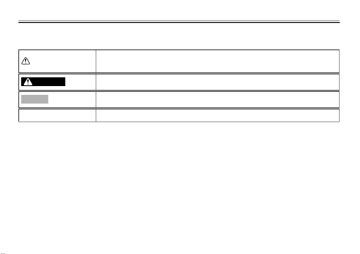
Particularly important information is distinguished in this manual by the following notations:
This is the safety alert symbol. It is used to alert you to potential personal injury
hazards. Obey all safety messages that follow this symbol to avoid possible injury
or death.
A WARNING indicates a hazardous situation which, if not avoided, could result in
death or serious injury.
A NOTICE indicates special precautions that must be taken to avoid damage to the
vehicle or other property.
A TIP provides key information to make procedures easier or clearer.
*Product and specifications are subject to change without notice.
EAU10133
IMPORTANT MANUAL INFORMATION
EAU10200
WR450FB
OWNER’S MANUAL
©2011 by Yamaha Motor Co., Ltd.
1st edition, September 2011
All rights reserved.
Any reprinting or unauthorized use
without the written permission of
Yamaha Motor Co., Ltd.
is expressly prohibited.
Printed in Japan.

TABLE OF CONTENTS
LOCATION OF IMPORTANT
LABELS ............................................. 1-1
SAFETY INFORMATION .................. 2-1
DESCRIPTION .................................. 3-1
Left view .......................................... 3-1
Right view ........................................ 3-2
Controls and instruments................. 3-3
INSTRUMENT AND CONTROL
FUNCTIONS ....................................... 4-1
Main switch ..................................... 4-1
Indicator lights and warning
lights ............................................ 4-1
Multi-function display ...................... 4-2
Handlebar switches ........................ 4-7
Clutch lever ..................................... 4-8
Shift pedal ....................................... 4-8
Brake lever ..................................... 4-8
Brake pedal .................................... 4-9
Fuel tank cap .................................. 4-9
Fuel ............................................... 4-10
Fuel tank breather hose ................ 4-11
Catalytic converter ........................ 4-11
Starter knob .................................. 4-12
Kickstarter ..................................... 4-12
Steering lock ................................. 4-13
Seat .............................................. 4-13
Adjusting the front fork .................. 4-14
Front fork bleeding ........................ 4-15
Adjusting the shock absorber
assembly ................................... 4-16
Sidestand ..................................... 4-18
Ignition circuit cut-off system ........ 4-19
FOR YOUR SAFETY –
PRE-OPERATION CHECKS ............. 5-1
OPERATION AND IMPORTANT
RIDING POINTS................................. 6-1
Starting a cold engine .................... 6-1
Starting a warm engine .................. 6-2
Shifting ........................................... 6-3
Tips for reducing fuel
consumption ............................... 6-3
Engine break-in .............................. 6-4
Parking ........................................... 6-5
PERIODIC MAINTENANCE AND
ADJUSTMENT ................................... 7-1
Owner’s tool kit ............................... 7-2
Periodic maintenance chart for
the emission control system ....... 7-3
General maintenance and
lubrication chart .......................... 7-4
Removing and installing the
panel ........................................... 7-7
Checking the spark plug ................. 7-7
Engine oil and oil filter element ...... 7-8
Coolant ......................................... 7-12
Cleaning the air filter element
and check hose ......................... 7-14
Adjusting the engine idling
speed ......................................... 7-17
Checking the throttle grip free
play ............................................ 7-17
Valve clearance ............................ 7-18
Tires .............................................. 7-18
Spoke wheels ............................... 7-20
Adjusting the clutch lever free
play ............................................ 7-20
Checking the brake lever free
play ............................................ 7-21
Checking the shift pedal ............... 7-22
Brake light switches ...................... 7-22
Checking the front and rear
brake pads ................................. 7-22
Checking the brake fluid level ....... 7-23
Changing the brake fluid ............... 7-24
Drive chain slack ........................... 7-24
Cleaning and lubricating the
drive chain ................................. 7-26
Checking and lubricating the
cables ........................................ 7-26
Checking and lubricating the
throttle grip and cable ................ 7-27
Checking and lubricating the
brake and clutch levers ............. 7-27
Checking and lubricating the
brake pedal ................................ 7-28

TABLE OF CONTENTS
Checking and lubricating the
sidestand ................................... 7-28
Lubricating the swingarm
pivots ......................................... 7-28
Checking the front fork ................. 7-29
Checking the steering ................... 7-29
Checking the wheel bearings ....... 7-30
Battery .......................................... 7-30
Replacing the fuse ........................ 7-31
Replacing the headlight bulb ........ 7-32
Tail/brake light .............................. 7-33
Replacing a turn signal light
bulb ........................................... 7-34
Replacing the license plate light
bulb ........................................... 7-34
Replacing an auxiliary light
bulb ........................................... 7-35
Supporting the motorcycle ............ 7-35
Front wheel ................................... 7-36
Rear wheel ................................... 7-37
Troubleshooting ............................ 7-39
Troubleshooting charts ................. 7-40
MOTORCYCLE CARE AND
STORAGE .......................................... 8-1
Matte color caution ......................... 8-1
Care ................................................ 8-1
Storage ........................................... 8-3
SPECIFICATIONS ............................ 9-1
CONSUMER INFORMATION .......... 10-1
Identification numbers .................. 10-1
Motorcycle noise regulation
(for Australia) ............................ 10-2
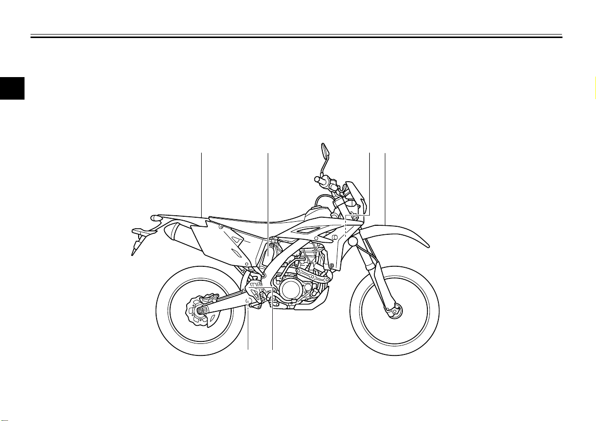
LOCATION OF IMPORTANT LABELS
3
8
4, 5
7
1, 2
6
Read and understand all of the labels on your vehicle. They contain important information for safe and proper operation of
your vehicle. Never remove any labels from your vehicle. If a label becomes difficult to read or comes off, a replacement label
1
is available from your Yamaha dealer.
EAU10384
1-1

LOCATION OF IMPORTANT LABELS
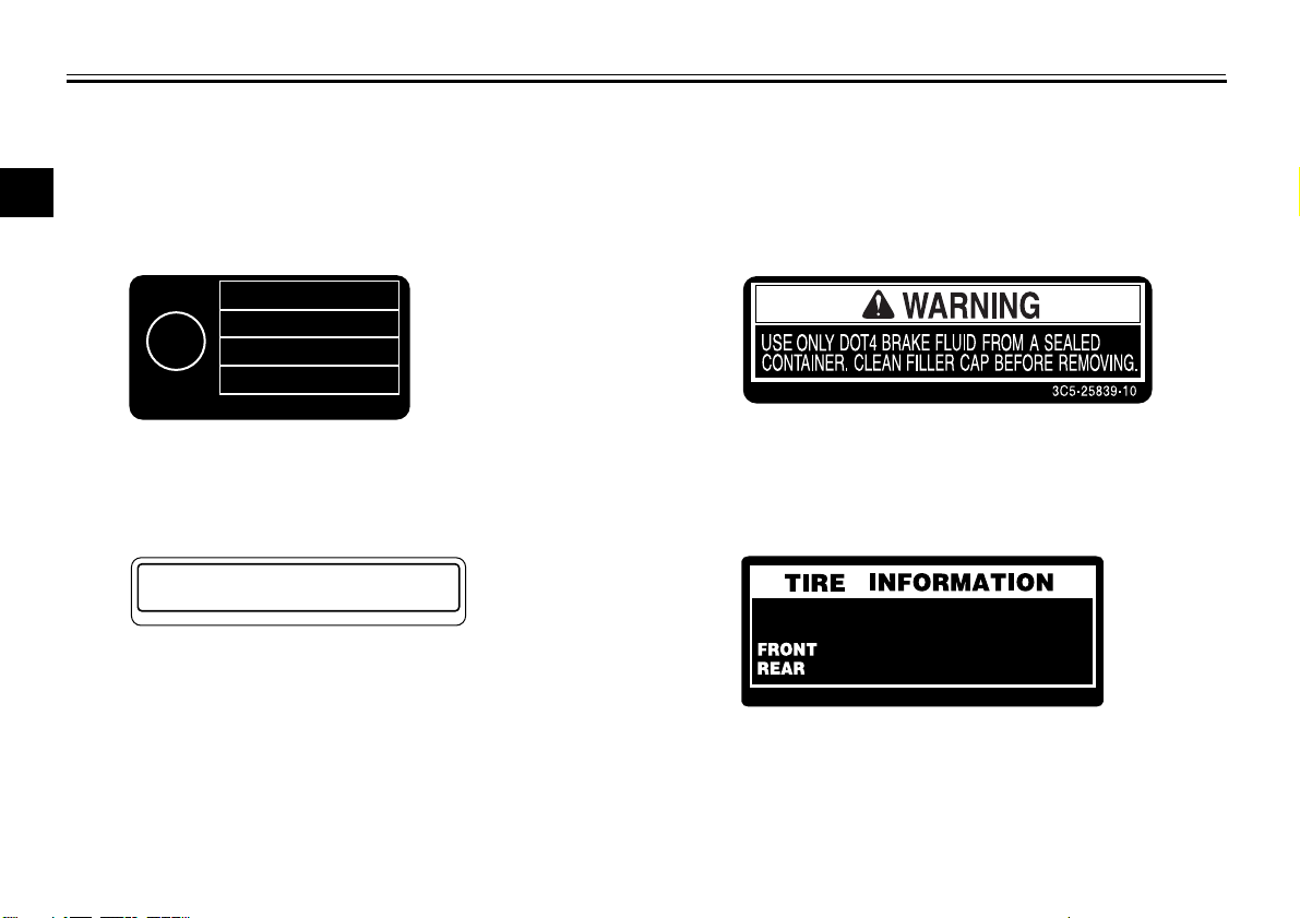
4AA-22259-40
WARNING
BEFORE YOU OPERATE THIS VEHICLE, READ
THE OWNER’S MANUAL AND ALL LABELS.
ALWAYS WEAR AN APPROVED MOTORCYCLE
HELMET, eye protection, and protective clothing.
5GK-2118K-00
STATIONARY NOISE TEST INFORMATION
TESTED 92 dB(A) AT 3750 r/min
SILENCING SYSTEM : YAMAHA
IDENTIFICATION :
5TJ-E0
1DX-2118G-10
1
2
3
4
1
2
3
1-2
4
5
6
7
8
9
LOCATION OF IMPORTANT LABELS
Cold tire normal pressure should be set
as follows.
: 150 },kPa, {1.50
kgf/cm222 psi
:
200
kPa, {
2.00
kgf/cm
2
},
29
psi
1DX-21668-A0
Use PREMIUM unleaded gasoline with
min. 95 octane(RON).
2S3-2817K-00
1DX-2811P-00
39R-00 9562
41R-03 9552
53R-01 0703
78R-03 5034
E
13
5
6
7
8
1
1-3
SAFETY INFORMATION
EAU53003
Be a Responsible Owner
As the vehicle’s owner, you are responsible for the safe and proper operation
of your motorcycle.
Motorcycles are single-track vehicles.
Their safe use and operation are dependent upon the use of proper riding
techniques as well as the expertise of
the operator. Every operator should
know the following requirements before
riding this motorcycle.
He or she should:
Obtain thorough instructions from
a competent source on all aspects
of motorcycle operation.
Observe the warnings and mainte-
nance requirements in this Owner’s Manual.
Obtain qualified training in safe
and proper riding techniques.
Obtain professional technical ser-
vice as indicated in this Owner’s
Manual and/or when made necessary by mechanical conditions.
Safe Riding
Perform the pre-operation checks each
time you use the vehicle to make sure it
is in safe operating condition. Failure to
inspect or maintain the vehicle properly
increases the possibility of an accident
or equipment damage. See page 5-1
for a list of pre-operation checks.
This motorcycle is designed to car-
ry the operator only.
No passengers.
This motorcycle is intended to use
as a competition model including
enduro usage.
This motorcycle is not designed
nor intended for continuous
“Paved Road” use. Never use this
motorcycle on highway (motorway)/expressway.
If any of the components that are
necessary for the vehicle to comply with regulations are modified or
replaced with non-specified components, the vehicle will no longer
meet the regulations.
Watch carefully for other vehicles
when operating on unpaved public
streets or roads. Make sure you
know your country’s laws and reg-
2-1
ulations before you ride on unpaved public streets or roads.
The failure of motorists to detect
and recognize motorcycles in traffic is the predominating cause of
automobile/motorcycle accidents.
Many accidents have been caused
by an automobile driver who did
not see the motorcycle. Making
yourself conspicuous appears to
be very effective in reducing the
chance of this type of accident.
Therefore:
• Wear a brightly colored jacket.
• Use extra caution when you are
approaching and passing
through intersections, since intersections are the most likely
places for motorcycle accidents
to occur.
• Ride where other motorists can
see you. Avoid riding in another
motorist’s blind spot.
Many accidents involve inexperi-
enced operators.
• Make sure that you are qualified
and that you only lend your motorcycle to other qualified operators.
2
3
4
5
6
7
8
9
SAFETY INFORMATION
• Know your skills and limits.
Staying within your limits may
help you to avoid an accident.
1
• We recommend that you practice riding your motorcycle until
2
you have become thoroughly familiar with the motorcycle and all
of its controls.
3
Many accidents have been caused
by error of the motorcycle opera-
4
tor. A typical error made by the operator is veering wide on a turn
5
due to excessive speed or undercornering (insufficient lean angle
for the speed).
6
• Always obey the speed limit and
never travel faster than warrant-
7
ed by road and traffic conditions.
• Always signal before turning or
8
9
changing lanes. Make sure that
other motorists can see you.
Ride cautiously in unfamiliar ar-
eas. You may encounter hidden
obstacles that could cause an accident.
The posture of the operator is im-
portant for proper control. The operator should keep both hands on
the handlebar and both feet on the
operator footrests during operation
to maintain control of the motorcycle.
Never ride under the influence of
alcohol or other drugs.
Protective Apparel
The majority of fatalities from motorcycle accidents are the result of head injuries. The use of a safety helmet is the
single most critical factor in the prevention or reduction of head injuries.
Always wear an approved helmet.
Wear a face shield or goggles.
Wind in your unprotected eyes
could contribute to an impairment
of vision that could delay seeing a
hazard.
The use of a jacket, heavy boots,
trousers, gloves, etc., is effective in
preventing or reducing abrasions
or lacerations.
Never wear loose-fitting clothes,
otherwise they could catch on the
control levers, footrests, or wheels
and cause injury or an accident.
Always wear protective clothing
that covers your legs, ankles, and
feet. The engine or exhaust sys-
2-2
tem become very hot during or after operation and can cause burns.
Avoid Carbon Monoxide Poisoning
All engine exhaust contains carbon
monoxide, a deadly gas. Breathing carbon monoxide can cause headaches,
dizziness, drowsiness, nausea, confusion, and eventually death.
Carbon Monoxide is a colorless, odorless, tasteless gas which may be
present even if you do not see or smell
any engine exhaust. Deadly levels of
carbon monoxide can collect rapidly
and you can quickly be overcome and
unable to save yourself. Also, deadly
levels of carbon monoxide can linger
for hours or days in enclosed or poorly
ventilated areas. If you experience any
symptoms of carbon monoxide poisoning, leave the area immediately, get
fresh air, and SEEK MEDICAL TREATMENT.
Do not run engine indoors. Even if
you try to ventilate engine exhaust
with fans or open windows and
doors, carbon monoxide can rapidly reach dangerous levels.
Do not run engine in poorly venti-

SAFETY INFORMATION
lated or partially enclosed areas
such as barns, garages, or carports.
Do not run engine outdoors where
engine exhaust can be drawn into
a building through openings such
as windows and doors.
Loading
Adding accessories or cargo to your
motorcycle can adversely affect stability and handling if the weight distribution
of the motorcycle is changed. To avoid
the possibility of an accident, use extreme caution when adding cargo or
accessories to your motorcycle. Use
extra care when riding a motorcycle
that has added cargo or accessories.
Here, along with the information about
accessories below, are some general
guidelines to follow if loading cargo to
your motorcycle:
The total weight of the operator, accessories and cargo must not exceed the
maximum load limit. Operation of an
overloaded vehicle could cause an
accident.
Maximum load:
90 kg (198 lb)
When loading within this weight limit,
keep the following in mind:
Shifting weights can create a sud-
den imbalance. Make sure that accessories are securely attached to
the motorcycle before riding.
Check accessory mounts frequently.
• Properly adjust the suspension
for your load (suspension-adjustable models only), and
check the condition and pressure of your tires.
• Never attach any large or heavy
items to the handlebar, front
fork, or front fender. These
items, including such cargo as
sleeping bags, duffel bags, or
tents, can create unstable handling or a slow steering response.
This vehicle is not designed to
pull a trailer or to be attached to
a sidecar.
2-3
Genuine Yamaha Accessories
Choosing accessories for your vehicle
is an important decision. Genuine
Yamaha accessories, which are available only from a Yamaha dealer, have
been designed, tested, and approved
by Yamaha for use on your vehicle.
Many companies with no connection to
Yamaha manufacture parts and accessories or offer other modifications for
Yamaha vehicles. Yamaha is not in a
position to test the products that these
aftermarket companies produce.
Therefore, Yamaha can neither endorse nor recommend the use of accessories not sold by Yamaha or
modifications not specifically recommended by Yamaha, even if sold and
installed by a Yamaha dealer.
Aftermarket Parts, Accessories,
and Modifications
While you may find aftermarket products similar in design and quality to
genuine Yamaha accessories, recognize that some aftermarket accessories
or modifications are not suitable because of potential safety hazards to you
or others. Installing aftermarket prod-
2
3
4
5
6
7
8
9

SAFETY INFORMATION
ucts or having other modifications performed to your vehicle that change any
of the vehicle’s design or operation
1
characteristics can put you and others
at greater risk of serious injury or death.
You are responsible for injuries related
2
to changes in the vehicle.
Keep the following guidelines in mind,
3
as well as those provided under “Loading” when mounting accessories.
Never install accessories that
4
would impair the performance of
5
6
7
8
9
your motorcycle. Carefully inspect
the accessory before using it to
make sure that it does not in any
way reduce ground clearance or
cornering clearance, limit suspension travel, steering travel or control operation, or obscure lights or
reflectors.
• Accessories fitted to the handlebar or the front fork area can
create instability due to improper
weight distribution. If accessories are added to the handlebar
or front fork area, they must be
as lightweight as possible and
should be kept to a minimum.
• Bulky or large accessories may
seriously affect the stability of
the motorcycle. Wind may attempt to lift the motorcycle, or
the motorcycle may become unstable in cross winds.
• Certain accessories can displace the operator from his or
her normal riding position. This
improper position limits the freedom of movement of the operator and may limit control ability,
therefore, such accessories are
not recommended.
Use caution when adding electri-
cal accessories. If electrical accessories exceed the capacity of the
motorcycle’s electrical system, an
electric failure could result, which
could cause a dangerous loss of
lights or engine power.
Aftermarket Tires and Rims
The tires and rims that came with your
motorcycle were designed to match the
performance capabilities and to provide
the best combination of handling, braking, and comfort. Other tires, rims, sizes, and combinations may not be
appropriate. Refer to page 7-18 for tire
2-4
specifications and more information on
replacing your tires.
Transporting the Motorcycle
Be sure to observe following instructions before transporting the motorcycle in another vehicle.
Remove all loose items from the
motorcycle.
Point the front wheel straight
ahead on the trailer or in the truck
bed, and choke it in a rail to prevent movement.
Shift the transmission in gear (for
models with a manual transmission).
Secure the motorcycle with
tie-downs or suitable straps that
are attached to solid parts of the
motorcycle, such as the frame or
upper front fork triple clamp (and
not, for example, to rubber-mounted handlebars or turn signals, or
parts that could break). Choose
the location for the straps carefully
so the straps will not rub against
painted surfaces during transport.
The suspension should be com-
pressed somewhat by the

tie-downs, if possible, so that the
motorcycle will not bounce excessively during transport.
SAFETY INFORMATION
2
3
4
5
6
7
8
9
2-5

DESCRIPTION
12
1, 2
3
4, 5
6
7810
9
11
Left view
1
2
3
4
EAU10410
5
6
7
8
1. Front fork compression damping force adjusting screw (page 4-14)
9
2. Bleed screw (page 4-15)
3. Starter knob (page 4-12)
4. Battery (page 7-30)
5. Main fuse (page 7-31)
6. Air filter element (page 7-14)
7. Engine oil check bolt (page 7-8)
8. Shift pedal (page 4-8)
9. Engine oil filler cap (page 7-8)
10.Engine oil drain bolt (oil tank) (page 7-8)
11.Engine oil dipstick (page 7-8)
12.Front fork rebound damping force adjusting screw (page 4-14)
3-1

Right view
1, 2
3
4
6710
5
9
11
8
DESCRIPTION
EAU10420
2
3
4
1. Shock absorber assembly compression damping force adjusting
screw (for slow compression damping) (page 4-16)
2. Shock absorber assembly compression damping force adjusting nut
(for fast compression damping) (page 4-16)
3. Kickstarter (page 4-12)
4. Radiator cap (page 7-12)
5. Steering lock (page 4-13)
6. Coolant drain bolt (page 7-13)
7. Brake pedal (page 4-9)
8. Engine oil drain bolt (crankcase) (page 7-8)
9. Rear brake fluid reservoir (page 7-23)
10.Shock absorber assembly rebound damping force adjusting screw
(page 4-16)
11.Rear brake light switch (page 7-22)
3-2
5
6
7
8
9
DESCRIPTION
12
3
4
5
6
8
7
9
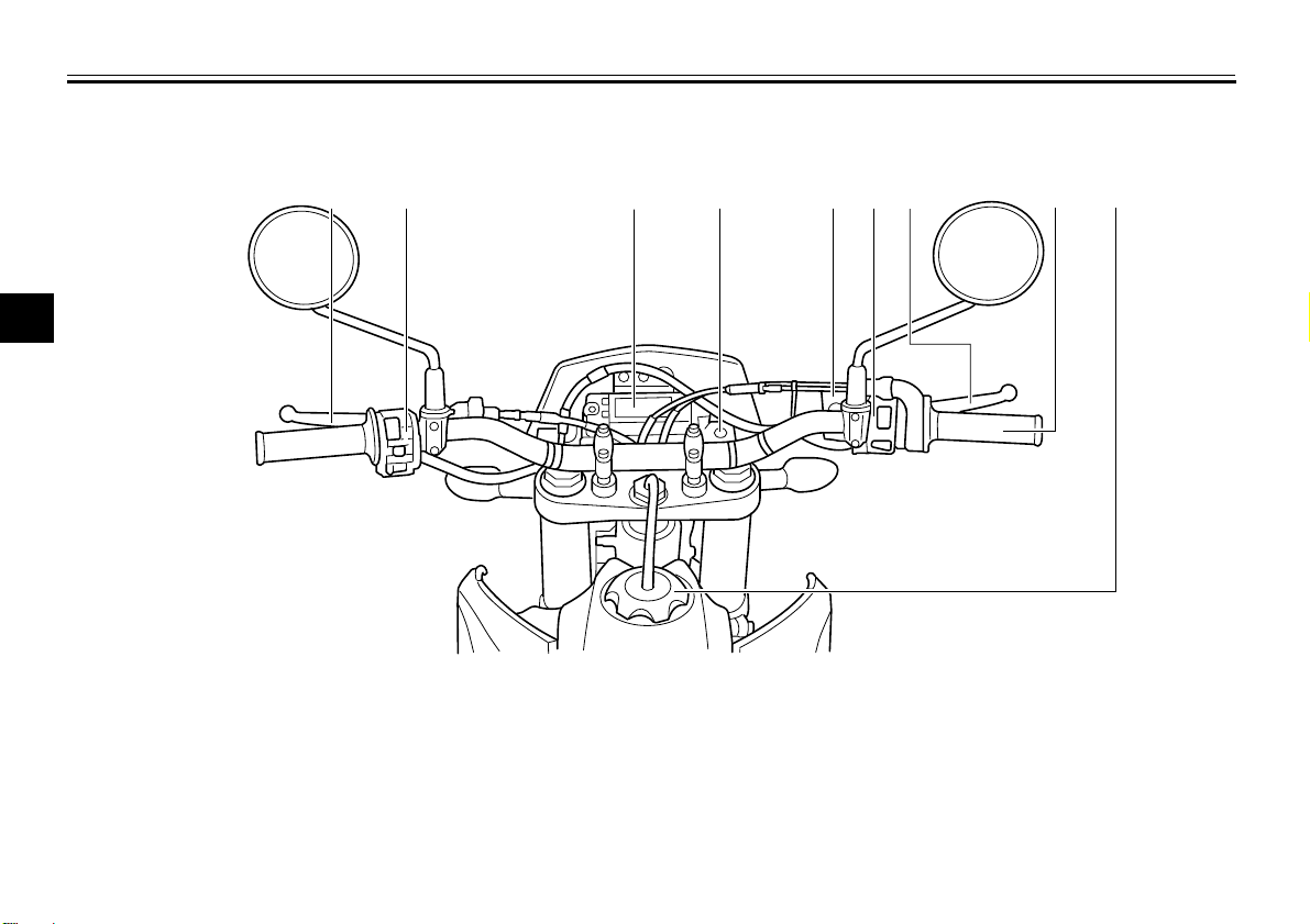
Controls and instruments
1
2
3
4
EAU10430
5
6
7
8
1. Clutch lever (page 4-8)
9
2. Left handlebar switches (page 4-7)
3. Multi-function display (page 4-2)
4. Main switch (page 4-1)
5. Front brake fluid reservoir (page 7-23)
6. Right handlebar switches (page 4-7)
7. Brake lever (page 4-8)
8. Throttle grip (page 7-17)
9. Fuel tank cap (page 4-9)
3-3

INSTRUMENT AND CONTROL FUNCTIONS
TIP
WARNING
NOTICE
1
2
3
4
5
EAU10450
Main switch
The main switch controls the ignition
and lighting systems. The various main
switch positions are described below.
EAU52430
ON
All electrical circuits are supplied with
power; the meter lighting, taillight, license plate light and auxiliary light
come on, and the engine can be started.
The headlight comes on automatically
when the engine is started and stays on
until the main switch is pushed to
“OFF”, even if the engine stalls.
EAU52471
OFF
All electrical systems are off.
EWA16130
Never push the main switch to
“OFF” while the vehicle is moving,
otherwise the electrical systems will
be switched off, which may result in
loss of control or an accident.
ECA17830
Make sure that the main switch is in
“OFF” with the engine turned off,
otherwise the battery may discharge
to the point that the starter motor
will not operate properly.
EAU49391
Indicator lights and warning lights
1. Neutral indicator light “ ”
2. High beam indicator light “ ”
3. Turn signal indicator light “ ”
4. Engine trouble warning light “ ”
5. Fuel level warning light “ ”
EAU11020
Turn signal indicator light “ ”
This indicator light flashes when the
turn signal switch is pushed to the left or
right.
EAU11060
Neutral indicator light “ ”
This indicator light comes on when the
transmission is in the neutral position.
2
3
4
5
6
7
8
9
4-1
INSTRUMENT AND CONTROL FUNCTIONS
WARNING
123 4
6
5
High beam indicator light “ ”
This indicator light comes on when the
high beam of the headlight is switched
1
on.
2
Fuel level warning light “ ”
This warning light comes on when the
3
fuel level drops below approximately
3.0 L (0.79 US gal, 0.66 Imp.gal). When
4
this occurs, refuel as soon as possible.
The electrical circuit of the warning light
can be checked by pushing the main
5
switch to “ON”. The warning light
should come on for a few seconds, and
6
then go off.
If the warning light does not come on
7
initially when the main switch is pushed
to “ON”, or if the warning light remains
on, have a Yamaha dealer check the
8
electrical circuit.
9
Engine trouble warning light “ ”
This warning light comes on or flashes
if a problem is detected in the electrical
circuit monitoring the engine. If this occurs, have a Yamaha dealer check the
vehicle.
EAU11080
EAU52390
EAU52400
The electrical circuit of the warning light
can be checked by pushing the main
switch to “ON”. The warning light
should come on for a few seconds, and
then go off.
If the warning light does not come on
initially when the main switch is pushed
to “ON”, or if the warning light remains
on, have a Yamaha dealer check the
electrical circuit.
4-2
EAU52982
Multi-function display
EWA12312
Be sure to stop the vehicle before
making any setting changes to the
multi-function display. Changing
settings while riding can distract the
operator and increase the risk of an
accident.
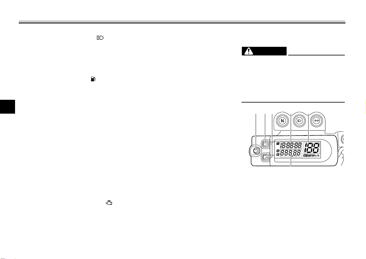
1. “RST” button
2. “SLCT 1” button
3. “SLCT 2” button
4. Clock/stopwatch
5. Speedometer
6. Odometer/tripmeter
INSTRUMENT AND CONTROL FUNCTIONS
TIP
TIP
12
3
1
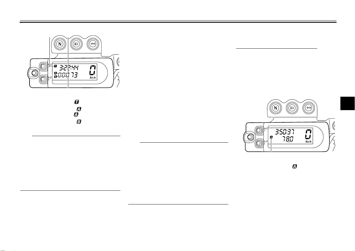
1. Stopwatch indicator “ ”
2. Tripmeter A indicator “ ”/Distance-compensation tripmeter “ ”
3. Tripmeter B indicator “ ”
The multi-function display can be
set to the basic mode or the measurement mode.
Tripmeter A will automatically re-
set to zero when changing from
the basic mode to the measurement mode or vice versa.
Basic mode:
a speedometer
an odometer
two tripmeters (which show the
distance traveled since they were
last set to zero)
a clock
Measurement mode:
a speedometer
a distance-compensation tripme-
ter (which shows the accumulated
distance traveled since set to zero
and which can be calibrated to provide a more accurate tripmeter
reading)
a stopwatch (which shows the time
that has been accumulated since
the start of stopwatch measurement)
Be sure to push the main switch to
“ON” before using the “SLCT 1”,
“SLCT 2” and “RST” buttons.
When the main switch is pushed to
“ON”, all of the display segments
of the multi-function display will appear and then disappear, in order
to test the electrical circuit.
4-3
Basic mode
Odometer and tripmeter modes
Push the “SLCT 2” button to switch the
display between the odometer mode
and the tripmeter modes A and B in the
following order:
odometer tripmeter A tripmeter B
odometer
1. Tripmeter A indicator “ ”
2
3
4
5
6
7
8
9

INSTRUMENT AND CONTROL FUNCTIONS
TIP
TIP
TIP
1
1
2
3
1. Tripmeter B indicator “ ”
4
5
Indicator “ ” comes on when tripmeter
A is selected, and indicator “ ” comes
on when tripmeter B is selected.
6
To reset a tripmeter, select it by push-
7
ing the “SLCT 2” button, and then push
the “RST” button for at least one second.
8
Clock
9
The clock displays when the main
switch is pushed to “ON”.
To set the clock
1. Push the “SLCT 1” button for at
least two seconds.
2. When the hour digits start flashing,
push either select button to set the
hours.
3. Push the “RST” button, and the
minute digits will start flashing.
4. Push either select button to set the
minutes.
5. Push the “RST” button, and the
second digits will start flashing.
6. Push either select button to set the
second digits to zero.
7. Push the “RST” button for at least
two seconds, and then release it to
start the clock.
When setting the clock, push the
“SLCT 1” button to increase the
digits or “SLCT 2” button to decrease the digits. Pushing and
holding either button will increase
or decrease the digits continuously
until the button is released.
If a button is not pushed within 30
seconds while setting the clock,
the clock will be set to the currently
displayed time.
4-4
Changing from the basic mode to
the measurement mode
With the odometer selected, push the
“SLCT 1” button and “SLCT 2” button
together for at least two seconds to
change to the measurement mode.
Changing from the measurement
mode to the basic mode
The stopwatch must be stopped before
changing to the basic mode.
1. Check that the stopwatch is not in
operation. If the stopwatch is in operation, stop it by pushing the
“SLCT 1” button and “SLCT 2” button together.
2. Push the “SLCT 1” button and
“SLCT 2” button together for at
least two seconds to change to the
basic mode.
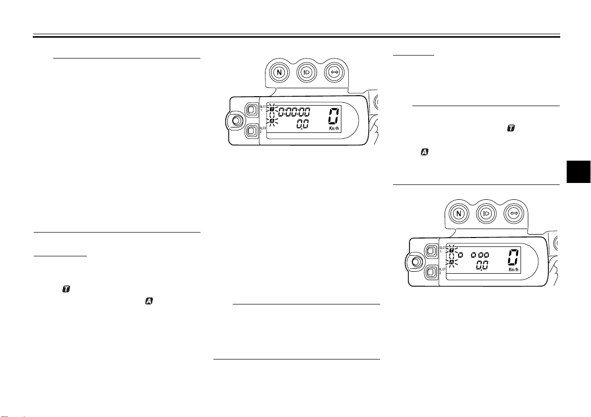
Measurement mode (for the stopwatch)
When the measurement mode is selected, the stopwatch is displayed and it
can be started manually or automatically.
TIP
Starting measurement consists of the
TIP
TIP
following two starts, either of which can
be selected.
Manual start
Starting measurement by the rider
himself operating the button. (A
long push on the “SLCT 2” button
will put measurement on standby.)
Auto start
Starting timer measurement automatically on detection of the movement of the machine. (A long push
on the “SLCT 1” button will put
measurement on standby.)
Manual start
The manual start is the default setting
for the stopwatch. The stopwatch indicator “ ” and the distance-compensation tripmeter indicator “ ” will start
flashing.
INSTRUMENT AND CONTROL FUNCTIONS
Auto start
1. Push the “SLCT 1” button for at
least two seconds to set the auto
start.
When the stopwatch is set to auto start,
the stopwatch indicator “ ” and the
distance-compensation tripmeter indicator “ ” will start flashing, and the dig-
1. Push the “RST” button to start the
stopwatch.
2. Push the “SLCT 1” button and
“SLCT 2” button together to stop
the stopwatch.
3. To resume stopwatch counting,
push the “SLCT 1” button and
“SLCT 2” button together.
To reset the stopwatch to zero,
push the “RST” button for at least
two seconds.
The stopwatch will continue counting
when the vehicle is stopped. To stop
and/or resume counting, repeat steps 2
and 3.
its in the display will start scrolling from
left to right.
2. When the vehicle starts moving,
the stopwatch will start counting.
3. Push the “SLCT 1” button and
“SLCT 2” button together to stop
the stopwatch.
4. To resume counting, push the
“SLCT 1” button and “SLCT 2” but-
2
3
4
5
6
7
8
9
4-5
INSTRUMENT AND CONTROL FUNCTIONS
TIP
TIP
TIP
ton together again.
The stopwatch will continue counting
1
when the vehicle is stopped. To stop
and/or resume counting, repeat steps 3
and 4.
2
3
Measurement mode (for calibrating
the distance-compensation tripmeter’s reading)
4
The distance-compensation tripmeter
is a feature intended to provide a more
5
accurate tripmeter reading for enduro
riding. Calibrating this meter in accor-
6
dance with the distances specified on
the enduro course map will help familiarize the rider with the course. In addi-
7
tion, calibrating the meter may also be
necessary when using tire, wheel,
8
chain sprocket sizes, etc. other than
specified. For further information concerning the use of this meter, please
9
consult your nearby Yamaha dealer.
Calibrate the distance-compensation
tripmeter as follows.
To increase the reading, push the
“SLCT 1” button. To decrease the reading, push the “SLCT 2” button. Pushing
and holding either button will increase
or decrease the reading continuously
until the button is released.
Calibrating the reading of the distance-compensation tripmeter is possible regardless of the stopwatch
operation.
Resetting the distance-compensation tripmeter or the distance-compensation tripmeter in combination
with the stopwatch
Resetting can be made only to the distance-compensation tripmeter or to the
distance-compensation tripmeter in
combination with the stopwatch.
Resetting the distance-compensation
tripmeter
1. Check that the stopwatch measurement is in operation.
2. Reset the distance-compensation
tripmeter to zero by pushing the
“RST” button for at least two seconds.
4-6
Resetting the distance-compensation
tripmeter in combination with the stopwatch
1. Stop the stopwatch.
2. Reset the distance-compensation
tripmeter and the stopwatch to
zero by pushing the “RST” button
for at least two seconds.

INSTRUMENT AND CONTROL FUNCTIONS
1
2
3
1
2
Handlebar switches
Left
1. Dimmer switch “ / ”
2. Turn signal switch “ / ”
3. Horn switch “ ”
Right
EAU1234A
EAU12400
Dimmer switch “ / ”
Set this switch to “ ” for the high
beam and to “ ” for the low beam.
EAU12460
Turn signal switch “ / ”
To signal a right-hand turn, push this
switch to “ ”. To signal a left-hand
turn, push this switch to “ ”. When released, the switch returns to the center
position. To cancel the turn signal
lights, push the switch in after it has returned to the center position.
EAU12500
Horn switch “ ”
Press this switch to sound the horn.
EAU12660
Engine stop switch “ / ”
Set this switch to “ ” before starting
the engine. Set this switch to “ ” to
stop the engine in case of an emergency, such as when the vehicle overturns
or when the throttle cable is stuck.
with the starter. See page 6-1 for starting instructions prior to starting the engine.
EAU52440
The engine trouble warning light will
come on when the main switch is
pushed to “ON” and the start switch is
pushed, but this does not indicate a
malfunction.
2
3
4
5
6
7
8
9
1. Engine stop switch “ / ”
2. Start switch “ ”
EAU12711
Start switch “ ”
Push this switch to crank the engine
4-7
INSTRUMENT AND CONTROL FUNCTIONS
1
1
1
4
3
(a)
(b)
2
5
Clutch lever
1
2
3
4
1. Clutch lever
5
The clutch lever is located at the left
handlebar grip. To disengage the
6
clutch, pull the lever toward the handlebar grip. To engage the clutch, release
7
the lever. The lever should be pulled
rapidly and released slowly for smooth
clutch operation.
8
The clutch lever is equipped with a
clutch switch, which is part of the igni-
9
tion circuit cut-off system. (See
page 4-19.)
EAU12820
Shift pedal
EAU12871
EAU41264
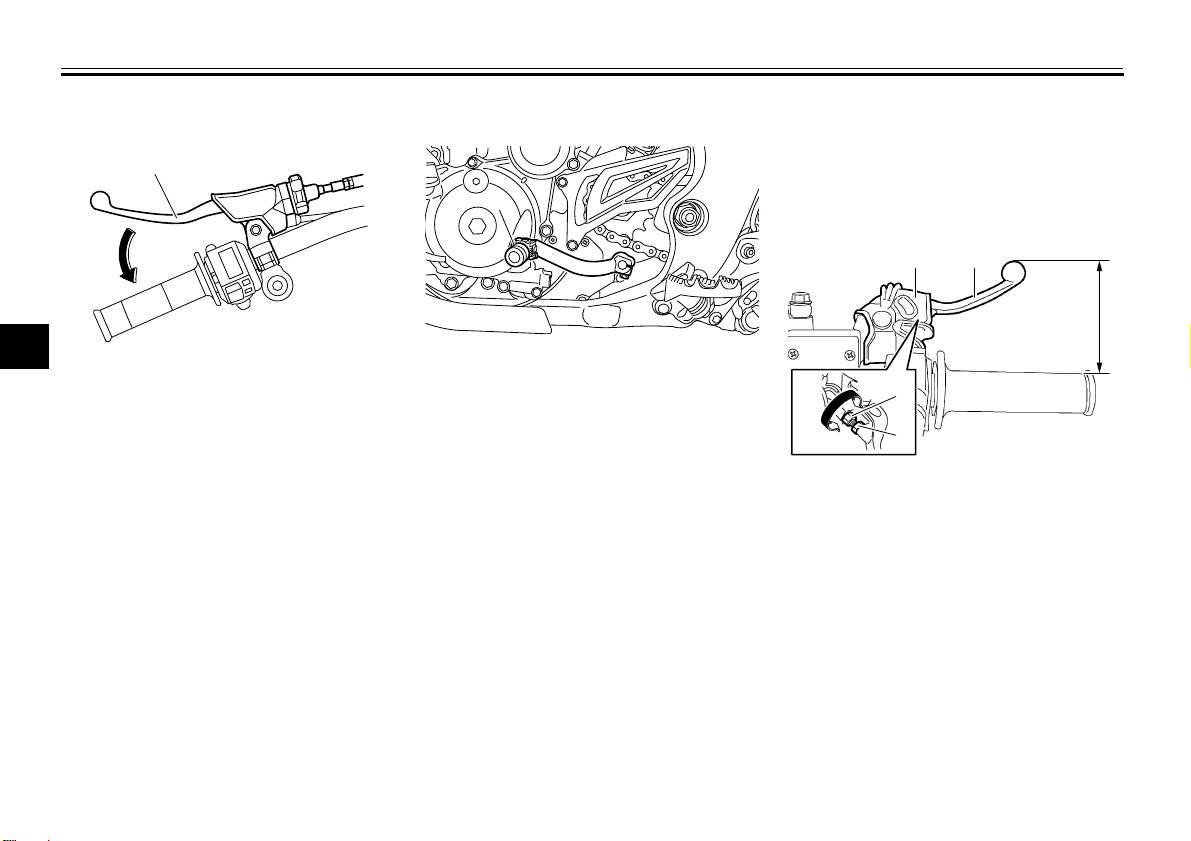
Brake lever
The brake lever is located on the right
side of the handlebar. To apply the front
brake, pull the lever toward the throttle
grip.
1. Shift pedal
The shift pedal is located on the left
side of the motorcycle and is used in
combination with the clutch lever when
shifting the gears of the 5-speed constant-mesh transmission equipped on
this motorcycle.
1. Rubber cover
2. Brake lever
3. Locknut
4. Brake lever position adjusting bolt
5. Distance between brake lever and throttle
grip
The brake lever is equipped with a
brake lever position adjusting bolt. Adjust the distance between the brake lever and the throttle grip as follows.
1. Slide the rubber cover toward the
end of the brake lever.
2. Loosen the locknut.
4-8
INSTRUMENT AND CONTROL FUNCTIONS
WARNING
1
1
3. While holding the lever pushed
away from the throttle grip, turn the
adjusting bolt in direction (a) to increase the distance, and in direction (b) to decrease it.
Distance between the brake lever
and the throttle grip:
Minimum (shortest):
76 mm (2.99 in)
Standard:
95 mm (3.74 in)
Maximum (longest):
97 mm (3.82 in)
4. Tighten the locknut.
5. Slide the rubber cover to its original position.
EAU12941
Brake pedal
1. Brake pedal
The brake pedal is on the right side of
the motorcycle. To apply the rear
brake, press down on the brake pedal.
EAU13182
Fuel tank cap
1. Fuel tank cap
To remove the fuel tank cap, turn it
counterclockwise, and then pull it off.
To install the fuel tank cap, insert it into
the tank opening, and then turn it clockwise.
EWA11091
Make sure that the fuel tank cap is
properly closed after filling fuel.
Leaking fuel is a fire hazard.
2
3
4
5
6
7
8
9
4-9

INSTRUMENT AND CONTROL FUNCTIONS
WARNING
WARNING
NOTICE
21
Fuel
Make sure there is sufficient gasoline in
the tank.
1
2
Gasoline and gasoline vapors are
extremely flammable. To avoid fires
3
and explosions and to reduce the
risk of injury when refueling, follow
these instructions.
4
1. Before refueling, turn off the en-
5
6
7
8
9
gine and be sure that no one is sitting on the vehicle. Never refuel
while smoking, or while in the vicinity of sparks, open flames, or
other sources of ignition such as
the pilot lights of water heaters and
clothes dryers.
2. Do not overfill the fuel tank. Stop
filling when the fuel reaches the
bottom of the filler tube. Because
fuel expands when it heats up,
heat from the engine or the sun
can cause fuel to spill out of the
fuel tank.
EAU13212
EWA10881
1. Fuel tank filler tube
2. Maximum fuel level
3. Wipe up any spilled fuel immediately. NOTICE: Immediately wipe
off spilled fuel with a clean, dry,
soft cloth, since fuel may deteriorate painted surfaces or plastic
parts.
[ECA10071]
4. Be sure to securely close the fuel
tank cap.
EWA15151
Gasoline is poisonous and can
cause injury or death. Handle gasoline with care. Never siphon gasoline by mouth. If you should swallow
some gasoline or inhale a lot of gasoline vapor, or get some gasoline in
4-10
your eyes, see your doctor immediately. If gasoline spills on your skin,
wash with soap and water. If gasoline spills on your clothing, change
your clothes.
EAU13391
Recommended fuel:
Premium unleaded gasoline only
Fuel tank capacity:
7.2 L (1.90 US gal, 1.58 Imp.gal)
Fuel reserve amount (when the fuel
level warning light comes on):
3.0 L (0.79 US gal, 0.66 Imp.gal)
ECA11400
Use only unleaded gasoline. The use
of leaded gasoline will cause severe
damage to internal engine parts,
such as the valves and piston rings,
as well as to the exhaust system.
Your Yamaha engine has been designed to use premium unleaded gasoline with a research octane number of
98 or higher. If knocking (or pinging) occurs, use a gasoline of a different
brand. Use of unleaded fuel will extend
INSTRUMENT AND CONTROL FUNCTIONS
TIP
WARNING
NOTICE
2
1
spark plug life and reduce maintenance
costs.
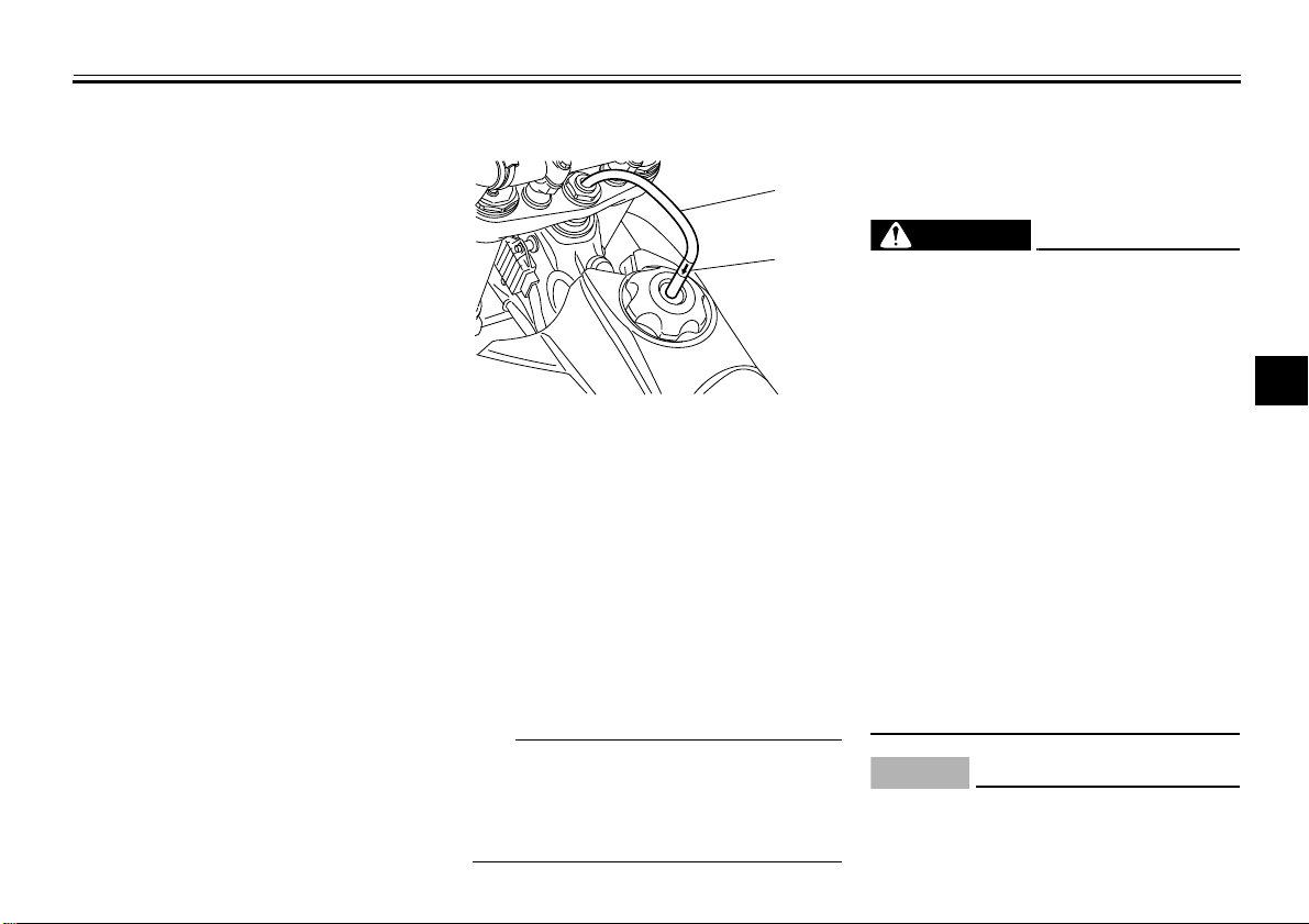
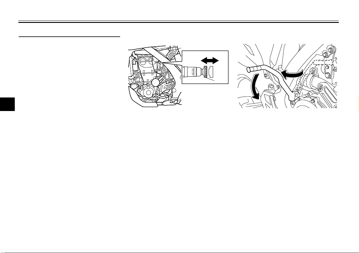
EAU41360
Fuel tank breather hose
1. Fuel tank breather hose
2. One-way valve
Before operating the motorcycle:
Check the fuel tank breather hose
connection.
Check the fuel tank breather hose
for cracks or damage, and replace
it if damaged.
Make sure that the end of the fuel
tank breather hose is not blocked,
and clean it if necessary.
If the fuel tank breather hose falls out,
reinstall it on the fuel tank cap with the
arrow mark on the one-way valve pointed downward as shown.
4-11
EAU13433
Catalytic converter
This model is equipped with a catalytic
converter in the exhaust system.
EWA10862
The exhaust system is hot after operation. To prevent a fire hazard or
burns:
Do not park the vehicle near
possible fire hazards such as
grass or other materials that
easily burn.
Park the vehicle in a place
where pedestrians or children
are not likely to touch the hot
exhaust system.
Make sure that the exhaust sys-
tem has cooled down before doing any maintenance work.
Do not allow the engine to idle
more than a few minutes. Long
idling can cause a build-up of
heat.
ECA10701
Use only unleaded gasoline. The use
of leaded gasoline will cause unrepairable damage to the catalytic
2
3
4
5
6
7
8
9
INSTRUMENT AND CONTROL FUNCTIONS
(a)(b)
1
1
1
2
3
4
5
6
7
8
9
converter.
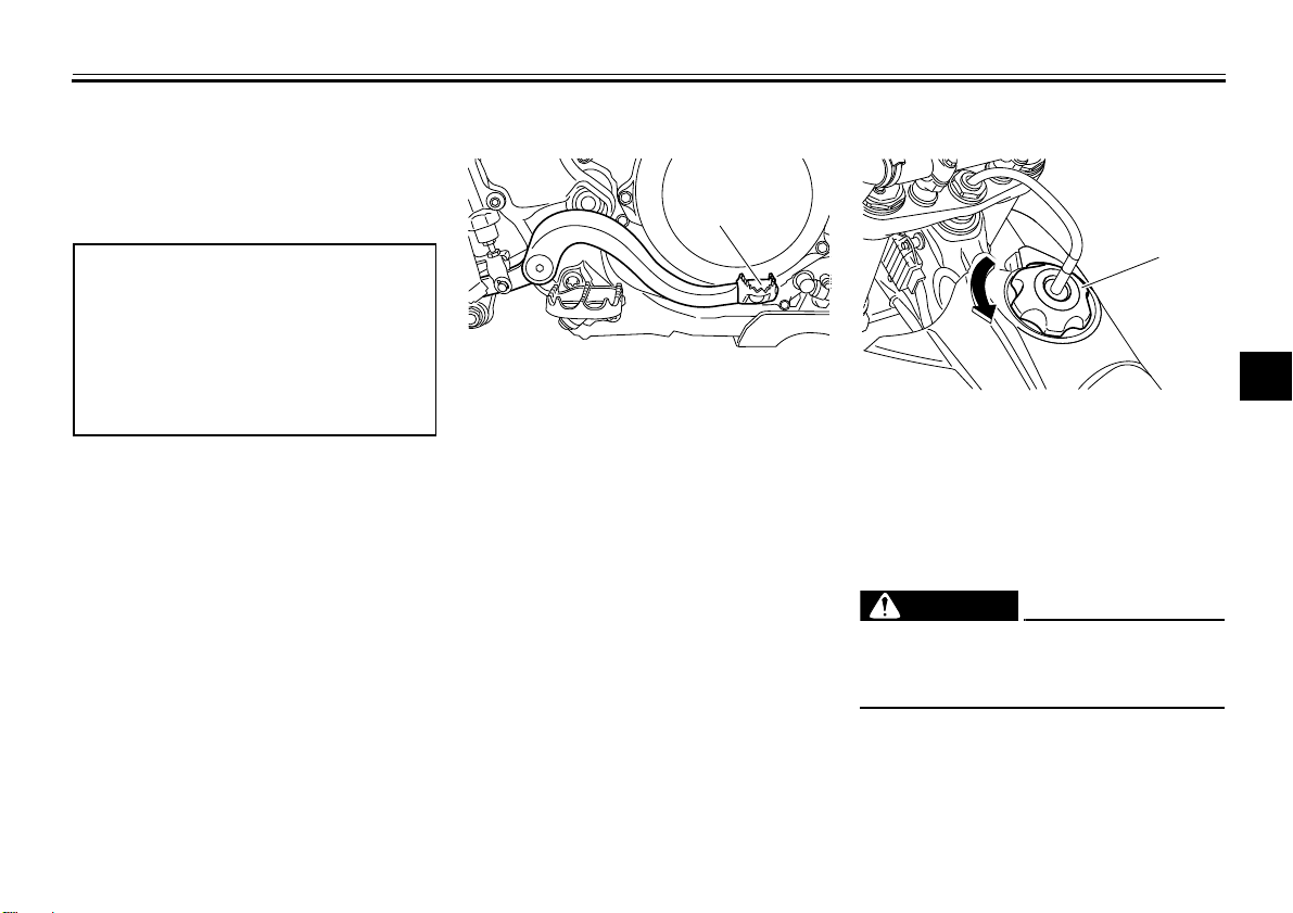
EAU53230
Starter knob
1. Starter knob/idle adjusting screw
Starting a cold engine requires a richer
air-fuel mixture, which is supplied by
the starter.
Move the knob in direction (a) to turn on
the starter.
Move the knob in direction (b) to turn off
the starter.
Kickstarter
1. Kickstarter lever
To start the engine, fold out the kickstarter lever, move it down lightly with
your foot until the gears engage, and
then push it down smoothly but forcefully. This model is equipped with a primary kickstarter, allowing the engine to
be started in any gear if the clutch is
EAU13650
disengaged. However, shifting the
transmission into the neutral position
before starting is recommended.
4-12
 Loading...