

Yamaha VX110 Owners Manual

WaveRunner
VX110 Sport
VX110 Deluxe
ASSEMBLY MANUAL
*LIT186660036*
F1K-28107-1G-11LIT-18666-00-36

E
WaveRunner
VX110 Sport/VX110 Deluxe
ASSEMBLY MANUAL
©2004 by Yamaha Motor Corporation, USA
1st Edition, October 2004
All rights reserved.
Any reprinting or unauthorized use
without the written permission of
Yamaha Motor Corporation, USA
is expressly prohibited.
Printed in USA
P/N LIT-18666-00-36

E
PREFACE
This Assembly Manual contains the information needed to assemble the Yamaha watercraft correctly prior to delivery to the customer.
Since some external parts of the watercraft
have not been assemblied at the Yamaha factory for convenience of packing, assembly by
the Yamaha dealer is required. It should be
noted that the reassembled watercraft should
be thoroughly cleaned, inspected, and
adjusted prior to delivery to the customer.
NOTICE
Because Yamaha constantly strives for product improvement, the service specifications
may be subject to change in the future. If any
change is introduced into the specifications or
assembly procedures, Yamaha dealers will be
notified by a technical bulletin.
SYMBOLS USED IN THIS
ASSEMBLY MANUAL
In order to simplify descriptions in assembly
manuals, the following symbols are used:
:Coat with water resistant grease.
(Yamaha grease A, Yamaha marine
grease)
:Tightening torque.
:Provide clearance.
:Install so that the arrow mark faces
upward.
:Frontword of the watercraft.
:Made of rubber or plastics.
:Tighten temporarily.
:Apply locking agent.
LOCTITE 242 (blue)
IMPORTANT MANUAL INFORMATION:
Particularly important information is distinguished in this manual by the following notations.
The safety Alert Symbol means ATTENTION! BECOME ALERT! YOUR
SAFETY IS INVOLVED!
WARNING
Failure to follow WARNING instructions
could result in severe injury or death
machine operator, passenger(s), a
bystander, or a person inspecting or repairing the watercraft.
to the
CAUTION:
A CAUTION indicates special precautions
that must be taken to avoid damage to the
watercraft.
Size:
d/D : Diameter of part.
l : Length of part.
NOTE:
A NOTE provides key information to make procedures easier or cleaner.
E
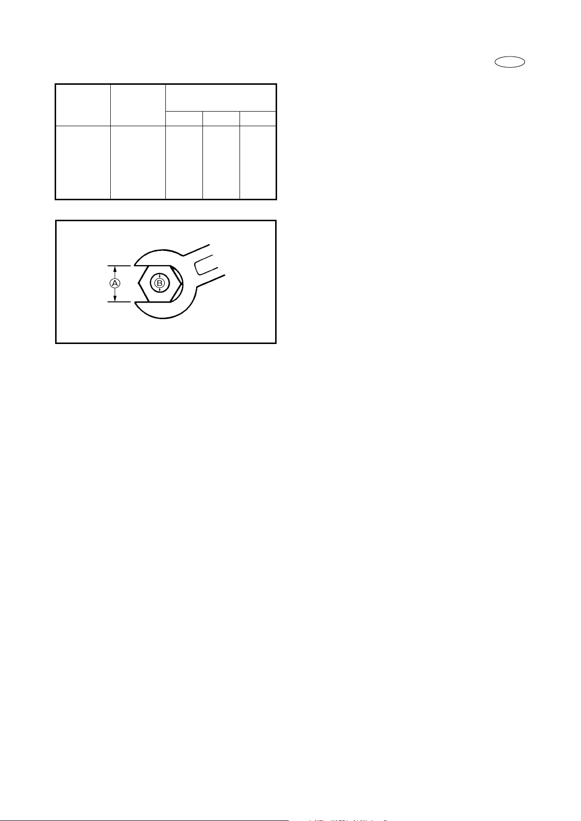
General torque
Nut A Bolt B
8 mm M5 5.0 0.5 3.6
10 mm M6 8.0 0.8 5.8
12 mm M8 18 1.8 13
14 mm M10 36 3.6 25
17 mm M12 43 4.3 31
specifications
N•mkgf•mft•lb
GENERAL TORQUE SPECIFICATIONS
This chart specifies the torques for tightening
standard fasteners with standard clean dry
ISO threads at room temperature. Torque
specifications for special components or
assemblies are given in applicable sections of
this manual. To avoid causing warpage,
tighten multi-fastener assemblies in a crisscross fashion, in progressive stages until the
specified torque is reached.

E
UNPACKING AND CHECKING
Carefully uncrate unit and inventory any missing or damaged parts.
NOTE:
For USA:
If concealed damage is found during uncrating, refer to the Yamaha Warranty Handbook, Chapter
3. Documentation may be required for warranty reimbursement. Do not continue with uncrating or
throw the crate away until the requirements in Chapter 3 have been met.
COMPARTMENT DIAGRAM
1
3
2
COMPARTMENT PART CHART
No. Part name Q’ty Remarks
1 Watercraft body 1
2 Handlebar assembly 1
3 Vinyl bag 3
4 Bow locker plate 1
5 Mirror 2
6 Basic orientation video 1
3
4
5
6
– 1 –
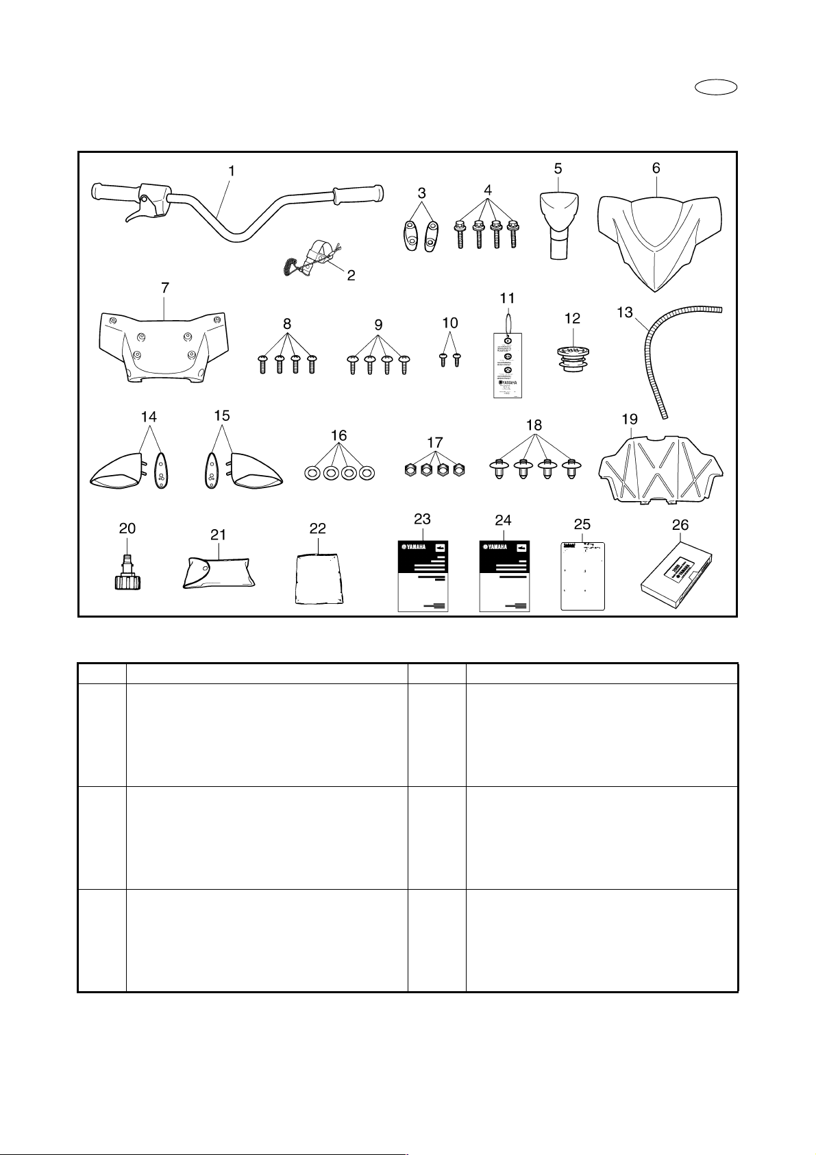
COMPARTMENT DIAGRAM
E
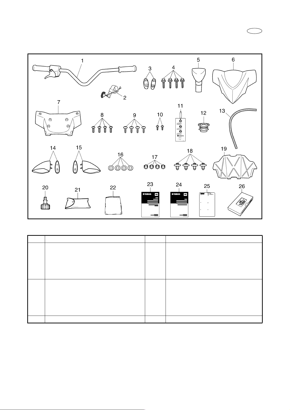
COMPARTMENT PART CHART
No. Part name Q’ty Part number
1 Handlebar assembly 1 F1K-U155A-00
2 Engine shut-off cord 1 EW2-68348-00
3 Upper handlebar holder 2 EU0-23814-30
4 Bolt 8 × 48 mm (0.31 × 1.89 in) 4 90119-089UU
5 Pad 1 F1K-U142D-00
6 Upper handlebar cover 1 F1K-U143D-01
7 Lower handlebar cover 1 F1K-U143E-00
8 Screw 6 × 13 mm (0.24 × 0.51 in) 4 90154-06017
9 Screw 5 × 15 mm (0.20 × 0.59 in) 4 90149-05903
10 Screw 4 × 9 mm (0.16 × 0.35 in) 2 90157-04003
11
Star label tag
12 Grommet 1 F0M-61469-00
13 Corrugated tube 1 F0D-6773E-00
14 Left mirror (with seal) 1 F1S-U596B-10
15 Right mirror (with seal) 1 F1S-U596C-10
*1
: For California
*1
1 F1B-U410M-00
– 2 –
E
No. Part name Q’ty Part number
16 Washer 18 × 8 mm (0.71 × 0.31 in) 4 9299R-08200
17 Nut 8 mm (0.31 in) 4 9572R-08300
18 Rivet 4 90269-08801
19 Storage compartment panel 1 F1K-U475F-01
20 Flushing hose connector 1 67X-E2590-00
21 Tool kit 1 F1B-65986-00
22 Vinyl bag 1 EU0-65901-01
23 Owner’s/Operator’s manual 1 F1K-F8199-10
24 Riding practice guide 1 F1K-F819T-10
25 Riding instruction card 1 FN8-U595B-04
26 Basic orientation video 1 F0D-U595A-01
– 3 –
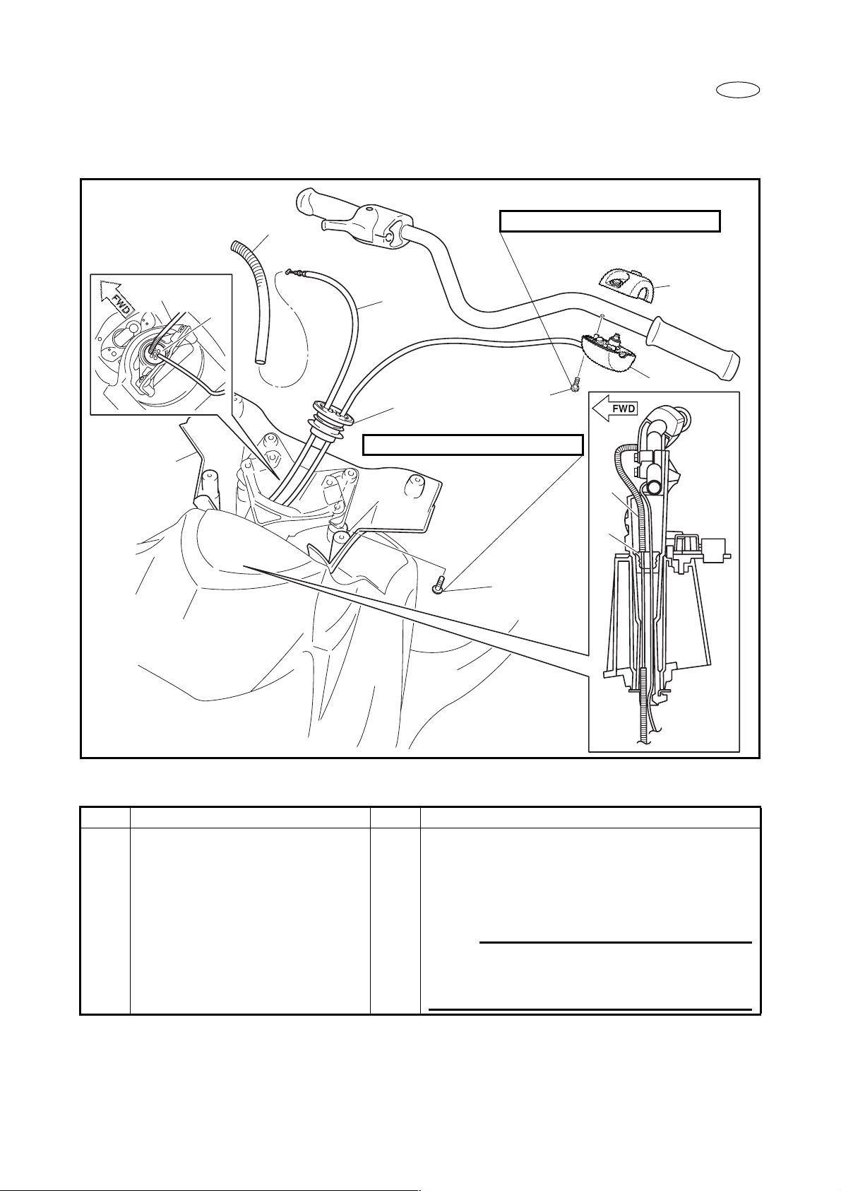
THROTTLE CABLE INSTALLATION
EXPLODED DIAGRAM
E
5
5
3
1
4
3
3.7 N • m (0.37 kgf • m, 2.7 ft • Ib)
3.4 N • m (0.34 kgf • m, 2.5 ft • Ib)
6
6
7
5
3
2
INSTALLATION CHART
Step Procedure/Part name Q’ty Service points
THROTTLE CABLE
INSTALLATION
1 Lower handlebar cover 1
2Screw
6 × 13 mm (0.24 × 0.51 in)
3 Grommet 1
Follow “Step” order for installation.
4
NOTE:
Pass the throttle cable and handlebar switch
lead through the grommet, and then fit the
grommet into the steering column.
– 4 –
 Loading...