

Yamaha TZR50 User Manual
5WX-F819D-E3
TZR50
OWNER’S MANUAL
Read this manual carefully
before operating this vehicle.

EAU46090
Read this manual carefully before operating this vehicle. This manual should stay with this vehicle if it is sold.

INTRODUCTION
EAU10102
Welcome to the Yamaha world of motorcycling!
As the owner of the TZR50, you are benefiting from Yamaha’s vast experience and newest technology regarding the
design and manufacture of high-quality products, which have earned Yamaha a reputation for dependability.
Please take the time to read this manual thoroughly, so as to enjoy all advantages of your TZR50. The Owner’s Manual
does not only instruct you in how to operate, inspect and maintain your motorcycle, but also in how to safeguard yourself and others from trouble and injury.
In addition, the many tips given in this manual will help keep your motorcycle in the best possible condition. If you have
any further questions, do not hesitate to contact your Yamaha dealer.
The Yamaha team wishes you many safe and pleasant rides. So, remember to put safety first!
Yamaha continually seeks advancements in product design and quality. Therefore, while this manual contains the most
current product information available at the time of printing, there may be minor discrepancies between your motorcycle and this manual. If there is any question concerning this manual, please consult a Yamaha dealer.
WARNING
Please read this manual carefully and completely before operating this motorcycle.
EWA10031
IMPORTANT MANUAL INFORMATION
Particularly important information is distinguished in this manual by the following notations:
This is the safety alert symbol. It is used to alert you to potential personal injury
hazards. Obey all safety messages that follow this symbol to avoid possible injury
or death.
EAU10132
WARNING
NOTICE
TIP
A WARNING indicates a hazardous situation which, if not avoided, could result in
death or serious injury.
A NOTICE indicates special precautions that must be taken to avoid damage to the
vehicle or other property.
A TIP provides key information to make procedures easier or clearer.
IMPORTANT MANUAL INFORMATION
EAUS1172
TZR50
OWNER’S MANUAL
©2008 by YAMAHA MOTOR ESPAÑA S.A.
1st edition, December 2008
All rights reserved.
Any reprinting or unauthorized use
without the written permission of
YAMAHA MOTOR ESPAÑA S.A.
is expressly prohibited.
Printed in Netherlands.

TABLE OF CONTENTS
SAFETY INFORMATION.....................1-1
DESCRIPTION.....................................2-1
Left view ...........................................2-1
Right view .........................................2-2
Controls and instruments .................2-3
INSTRUMENT AND CONTROL
FUNCTIONS ........................................3-1
Main switch/steering lock.................3-1
Indicator and warning lights .............3-2
Turn signal indicator light ................3-2
Neutral indicator light ......................3-2
Oil level warning light ......................3-2
Coolant temperature warning light ..3-3
Engine trouble warning light ............3-3
Speedometer unit .............................3-3
Tachometer .......................................3-4
Handlebar switches ..........................3-4
Pass switch ......................................3-4
Dimmer switch .................................3-4
Turn signal switch ............................3-4
Horn switch .....................................3-4
Engine stop switch ..........................3-5
Start switch ......................................3-5
Clutch lever.......................................3-5
Shift pedal.........................................3-5
Brake lever........................................3-6
Brake pedal.......................................3-6
Fuel tank cap ....................................3-6
Fuel ...................................................3-7
Fuel tank breather/overflow hose.....3-8
Catalytic converter............................3-9
2-stroke engine oil............................3-9
Fuel cock ........................................3-10
Starter (choke) lever ......................3-11
Seat.................................................3-11
Anti-theft device housing................3-12
Rear view mirrors............................3-12
Sidestand........................................3-13
Ignition circuit cut-off system.........3-13
FOR YOUR SAFETY –
PRE-OPERATION CHECKS ...............4-1
Pre-operation check list....................4-2
OPERATION AND IMPORTANT
RIDING POINTS..................................5-1
Starting a cold engine ......................5-1
Starting a warm engine ....................5-2
Shifting..............................................5-2
Tips for reducing fuel
consumption..................................5-3
Engine break-in.................................5-3
Parking..............................................5-4
PERIODIC MAINTENANCE AND
ADJUSTMENT ....................................6-1
Owner’s tool kit.................................6-1
Periodic maintenance chart for the
emission control system ...............6-3
General maintenance and lubrication
chart ..............................................6-4
Removing and installing cowlings
and panels.....................................6-8
Checking the spark plug ................6-10
Transmission oil ..............................6-11
Coolant ...........................................6-13
Air filter element..............................6-15
Adjusting the carburetor.................6-16
Adjusting the engine idling speed ..6-16
Adjusting the throttle cable free
play..............................................6-17
Tires ................................................6-17
Cast wheels ....................................6-19
Adjusting the clutch lever free
play..............................................6-19
Checking the front brake lever free
play..............................................6-20
Adjusting the brake pedal free
play..............................................6-20
Adjusting the shift pedal position...6-21
Adjusting the rear brake light
switch ..........................................6-21
Checking the front and rear brake
pads.............................................6-21
Checking the brake fluid level ........6-22
Changing the brake fluid ................6-23
Drive chain slack.............................6-24
Cleaning and lubricating the drive
chain............................................6-25

TABLE OF CONTENTS
Checking and lubricating the
cables ..........................................6-26
Checking and lubricating the throttle
grip and cable .............................6-26
Adjusting the Autolube pump.........6-27
Checking and lubricating the brake
and shift pedals...........................6-27
Checking and lubricating the brake
and clutch levers .........................6-27
Checking and lubricating the
sidestand.....................................6-28
Checking the front fork...................6-28
Checking the steering.....................6-29
Checking the wheel bearings .........6-30
Battery ............................................6-30
Replacing the fuse..........................6-31
Replacing the headlight bulb..........6-32
Replacing the tail/brake light
bulb .............................................6-33
Replacing a front turn signal light
bulb .............................................6-34
Replacing a rear turn signal light
bulb .............................................6-34
Replacing the license plate light
bulb .............................................6-35
Troubleshooting ..............................6-36
Troubleshooting charts ...................6-37
Care ..................................................7-1
Storage .............................................7-3
SPECIFICATIONS ...............................8-1
CONSUMER INFORMATION .............9-1
Identification numbers ......................9-1
Key identification number.................9-1
Vehicle identification number............9-1
Model label .......................................9-2
MOTORCYCLE CARE AND
STORAGE............................................7-1
Matte color caution...........................7-1
SAFETY INFORMATION
Be a Responsible Owner
As the vehicle’s owner, you are res-
1
ponsible for the safe and proper operation of your motorcycle.
Motorcycles are single-track vehicles.
Their safe use and operation are
dependent upon the use of proper
riding techniques as well as the
expertise of the operator. Every operator should know the following requirements before riding this motorcycle.
He or she should:
● Obtain thorough instructions
from a competent source on all
aspects of motorcycle operation.
● Observe the warnings and main-
tenance requirements in this
Owner’s Manual.
● Obtain qualified training in safe
and proper riding techniques.
● Obtain professional technical
service as indicated in this
Owner’s Manual and/or when
made necessary by mechanical
conditions.
EAU10283
Safe Riding
Perform the pre-operation checks
each time you use the vehicle to
make sure it is in safe operating condition. Failure to inspect or maintain
the vehicle properly increases the
possibility of an accident or equipment damage. See page 4-2 for a list
of pre-operation checks.
● This motorcycle is designed to
carry the operator and a passenger.
● The failure of motorists to detect
and recognize motorcycles in
traffic is the predominating cause
of automobile/motorcycle accidents. Many accidents have
been caused by an automobile
driver who did not see the
motorcycle. Making yourself
conspicuous appears to be very
effective in reducing the chance
of this type of accident.
Therefore:
• Wear a brightly colored jacket.
• Use extra caution when you
are approaching and passing
through intersections, since
1-1
intersections are the most
likely places for motorcycle
accidents to occur.
• Ride where other motorists can
see you. Avoid riding in another motorist’s blind spot.
● Many accidents involve inexpe-
rienced operators. In fact, many
operators who have been involved in accidents do not even
have a current motorcycle license.
• Make sure that you are qualified and that you only lend your
motorcycle to other qualified
operators.
• Know your skills and limits.
Staying within your limits may
help you to avoid an accident.
• We recommend that you practice riding your motorcycle
where there is no traffic until
you have become thoroughly
familiar with the motorcycle
and all of its controls.
● Many accidents have been cau-
sed by error of the motorcycle
operator. A typical error made by
the operator is veering wide on a

SAFETY INFORMATION
turn due to excessive speed or
undercornering (insufficient lean
angle for the speed).
• Always obey the speed limit
and never travel faster than
warranted by road and traffic
conditions.
• Always signal before turning or
changing lanes. Make sure that
other motorists can see you.
● The posture of the operator and
passenger is important for proper
control.
• The operator should keep both
hands on the handlebar and
both feet on the operator footrests during operation to
maintain control of the
motorcycle.
• The passenger should always
hold onto the operator, the seat
strap or grab bar, if equipped,
with both hands and keep both
feet on the passenger footrests. Never carry a passenger
unless he or she can firmly place both feet on the passenger
footrests.
● Never ride under the influence of
alcohol or other drugs.
● This motorcycle is designed for
on-road use only. It is not suitable
for off-road use.
Protective apparel
The majority of fatalities from
motorcycle accidents are the result of
head injuries. The use of a safety helmet is the single most critical factor in
the prevention or reduction of head
injuries.
● Always wear an approved hel-
met.
● Wear a face shield or goggles.
Wind in your unprotected eyes
could contribute to an impairment of vision that could delay
seeing a hazard.
● The use of a jacket, heavy boots,
trousers, gloves, etc., is effective
in preventing or reducing abrasions or lacerations.
● Never wear loose-fitting clothes,
otherwise they could catch on
the control levers, footrests, or
wheels and cause injury or an
accident.
1-2
● Always wear protective clothing
that covers your legs, ankles, and
feet. The engine or exhaust system become very hot during or
after operation and can cause
burns.
● A passenger should also observe
the above precautions.
Avoid Carbon Monoxide Poisoning
All engine exhaust contains carbon
monoxide, a deadly gas. Breathing
carbon monoxide can cause headaches, dizziness, drowsiness, nausea,
confusion, and eventually death.
Carbon Monoxide is a colorless,
odorless, tasteless gas which may be
present even if you do not see or
smell any engine exhaust. Deadly
levels of carbon monoxide can collect
rapidly and you can quickly be overcome and unable to save yourself.
Also, deadly levels of carbon monoxide can linger for hours or days in
enclosed or poorly ventilated areas. If
you experience any symptoms of carbon monoxide poisoning, leave the
area immediately, get fresh air, and
SEEK MEDICAL TREATMENT.
1
SAFETY INFORMATION
● Do not run engine indoors. Even
if you try to ventilate engine
1
exhaust with fans or open windows and doors, carbon monoxide can rapidly reach dangerous
levels.
● Do not run engine in poorly venti-
lated or partially enclosed areas
such as barns, garages, or carports.
● Do not run engine outdoors whe-
re engine exhaust can be drawn
into a building through openings
such as windows and doors.
Loading
Adding accessories or cargo to your
motorcycle can adversely affect stability and handling if the weight distribution of the motorcycle is changed.
To avoid the possibility of an accident, use extreme caution when
adding cargo or accessories to your
motorcycle. Use extra care when
riding a motorcycle that has added
cargo or accessories. Here, along
with the information about accessories below, are some general guidelines to follow if loading cargo to your
motorcycle:
The total weight of the operator, passenger, accessories and cargo must
not exceed the maximum load limit.
Operation of an overloaded vehicle
could cause an accident.
Maximum load:
196 kg (432 lb)
When loading within this weight limit,
keep the following in mind:
● Cargo and accessory weight
should be kept as low and close
to the motorcycle as possible.
Securely pack your heaviest
items as close to the center of
the vehicle as possible and make
sure to distribute the weight as
evenly as possible on both sides
of the motorcycle to minimize
imbalance or instability.
● Shifting weights can create a
sudden imbalance. Make sure
that accessories and cargo are
securely attached to the
motorcycle before riding. Check
accessory mounts and cargo restraints frequently.
1-3
• Properly adjust the suspension
for your load (suspensionadjustable models only), and
check the condition and pressure of your tires.
• Never attach any large or
heavy items to the handlebar,
front fork, or front fender. These items, including such cargo
as sleeping bags, duffel bags,
or tents, can create unstable
handling or a slow steering response.
● This vehicle is not designed to
pull a trailer or to be attached
to a sidecar.
Genuine Yamaha Accessories
Choosing accessories for your vehicle
is an important decision. Genuine
Yamaha accessories, which are available only from a Yamaha dealer, have
been designed, tested, and approved
by Yamaha for use on your vehicle.
Many companies with no connection
to Yamaha manufacture parts and
accessories or offer other modifications for Yamaha vehicles. Yamaha is
not in a position to test the products
SAFETY INFORMATION
that these aftermarket companies
produce. Therefore, Yamaha can neither endorse nor recommend the use
of accessories not sold by Yamaha or
modifications not specifically recommended by Yamaha, even if sold and
installed by a Yamaha dealer.
Aftermarket Parts, Accessories,
and Modifications
While you may find aftermarket products similar in design and quality to
genuine Yamaha accessories, recognize that some aftermarket accessories or modifications are not suitable
because of potential safety hazards to
you or others. Installing aftermarket
products or having other modifications performed to your vehicle that
change any of the vehicle’s design or
operation characteristics can put you
and others at greater risk of serious
injury or death. You are responsible
for injuries related to changes in the
vehicle.
Keep the following guidelines in mind,
as well as those provided under “Loading” when mounting accessories.
● Never install accessories or carry
cargo that would impair the performance of your motorcycle. Carefully inspect the accessory before
using it to make sure that it does
not in any way reduce ground clearance or cornering clearance, limit
suspension travel, steering travel
or control operation, or obscure
lights or reflectors.
• Accessories fitted to the handlebar or the front fork area can
create instability due to improper weight distribution or
aerodynamic changes. If
accessories are added to the
handlebar or front fork area,
they must be as lightweight as
possible and should be kept to
a minimum.
• Bulky or large accessories may
seriously affect the stability of
the motorcycle due to aerodynamic effects. Wind may
attempt to lift the motorcycle,
or the motorcycle may become
unstable in cross winds. These
accessories may also cause
instability when passing or
1-4
being passed by large vehicles.
• Certain accessories can displace the operator from his or her
normal riding position. This
improper position limits the freedom of movement of the operator and may limit control ability,
therefore, such accessories are
not recommended.
● Use caution when adding electri-
cal accessories. If electrical
accessories exceed the capacity
of the motorcycle’s electrical system, an electric failure could
result, which could cause a dangerous loss of lights or engine
power.
Aftermarket Tires and Rims
The tires and rims that came with your
motorcycle were designed to match
the performance capabilities and to
provide the best combination of
handling, braking, and comfort. Other
tires, rims, sizes, and combinations
may not be appropriate. Refer to
page 6-17 for tire specifications and
more information on replacing your
tires.
1
DESCRIPTION
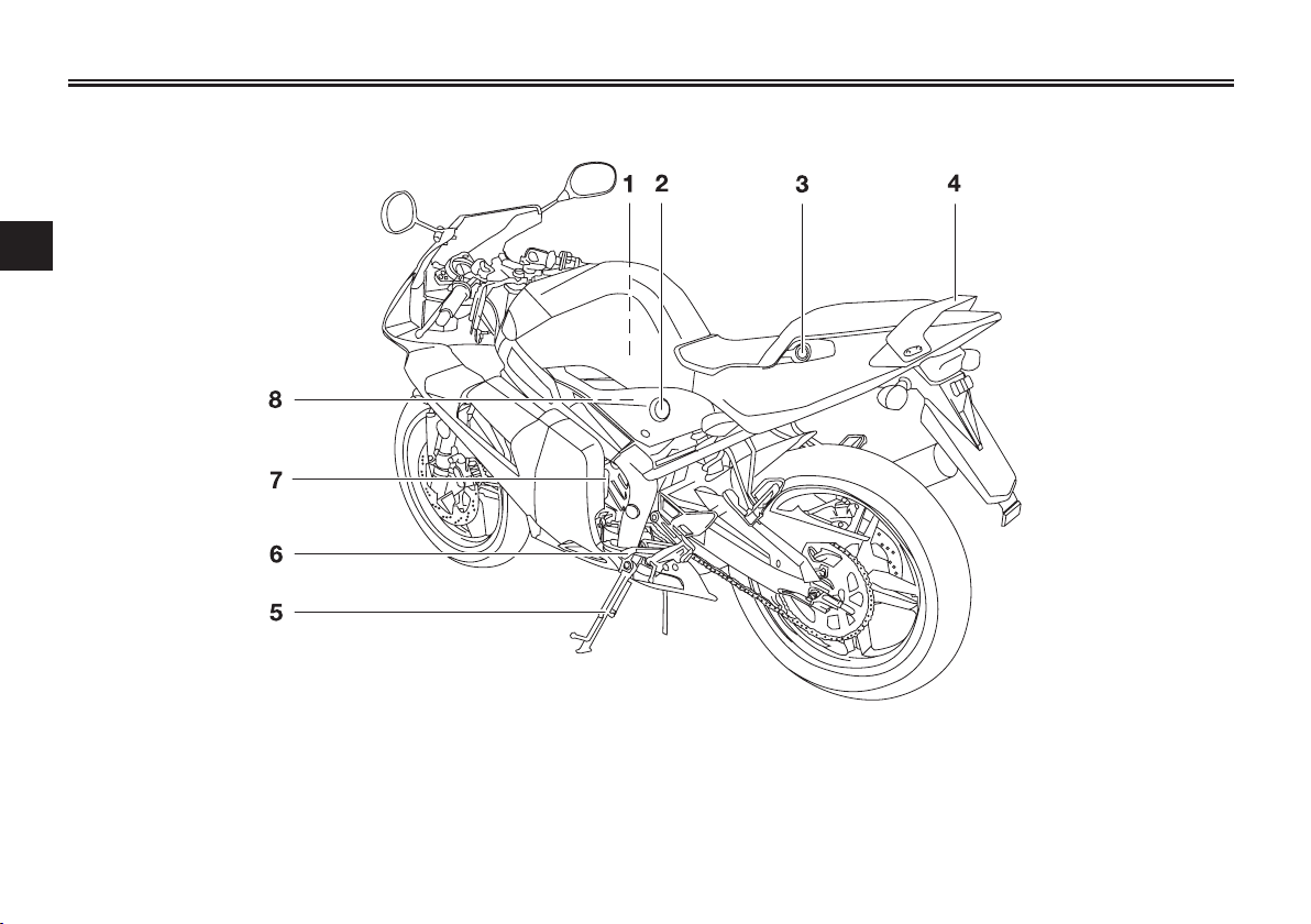
Left view
2
EAU10410
1. Air filter (page 6-15)
2. Fuel cock (page 3-10)
3. Seat lock (page 3-11)
4. Grab bar
5. Sidestand (page 3-13, 6-28)
6. Shift pedal (page 3-5)
7. Coolant reservoir (page 6-13)
8. Idle adjusting screw (page 6-16)
2-1
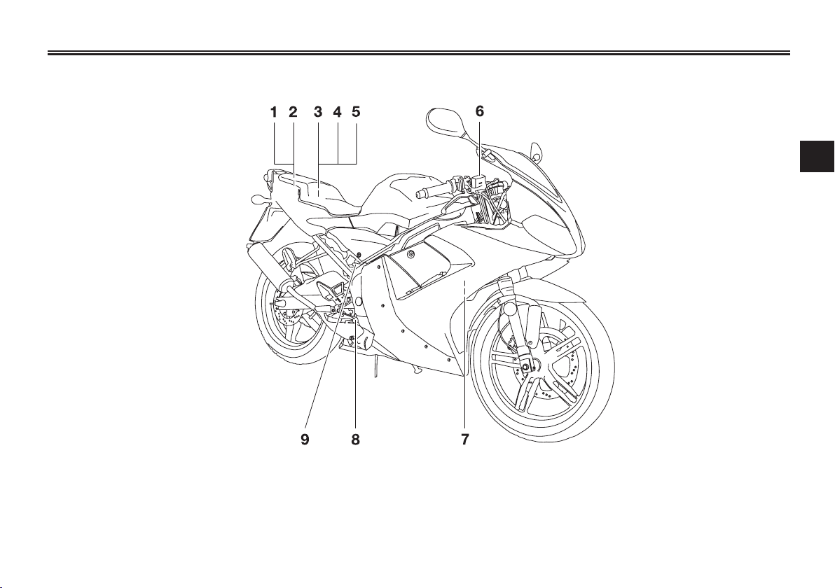
Right view
DESCRIPTION
EAU10420
2
1. Storage compartment (page 3-12)
2. Owner’s tool kit (page 6-1)
3. Battery (page 6-30)
4. Fuse (page 6-31)
5. Oil tank cap (page 3-9)
6. Front brake fluid reservoir (page 6-22)
7. Radiator (page 6-13)
8. Brake pedal (page 3-6)
9. Rear brake fluid reservoir (page 6-22)
2-2

DESCRIPTION
Controls and instruments
2
EAU10430
1. Clutch lever (page 3-5)
2. Left handlebar switches (page 3-4)
3. Tachometer (page 3-4)
4. Main switch/steering lock (page 3-1)
5. Speedometer (page 3-3)
6. Right handlebar switches (page 3-4)
7. Throttle grip (page 6-17)
8. Front brake lever (page 3-6)
9. Fuel tank cap (page 3-6)
2-3
INSTRUMENT AND CONTROL FUNCTIONS
EAU10460
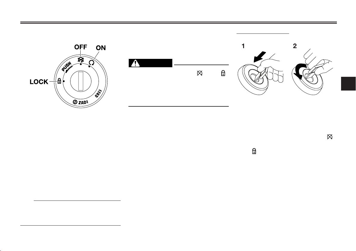
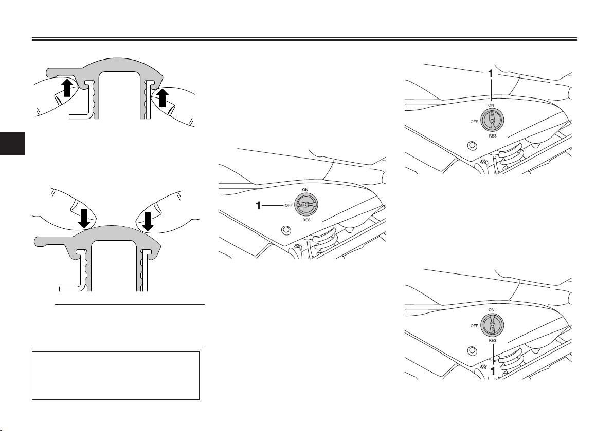
Main switch/steering lock
The main switch/steering lock controls the ignition and lighting systems,
and is used to lock the steering. The
various positions are described
below.
EAU10640
ON
All electrical circuits are supplied with
power, and the engine can be started.
The key cannot be removed.
TIP
The headlight, meter lighting and taillight come on automatically when the
engine is started.
EAU10661
OFF
All electrical systems are off. The key
can be removed.
EWA10061
WARNING
Never turn the key to “ ” or “ ”
while the vehicle is moving. Otherwise the electrical systems will be
switched off, which may result in
loss of control or an accident.
EAU10681
LOCK
The steering is locked, and all electrical systems are off. The key can be
removed.
To lock the steering
3
1. Push.
2. Turn.
1. Turn the handlebars all the way to
the left.
2. Push the key in from the “ ”
position, and then turn it to
“ ” while still pushing it.
3. Remove the key.
3-1
INSTRUMENT AND CONTROL FUNCTIONS
To unlock the steering
3
1. Push.
2. Turn.
Push the key in, and then turn it to
“ ” while still pushing it.
EAU11004
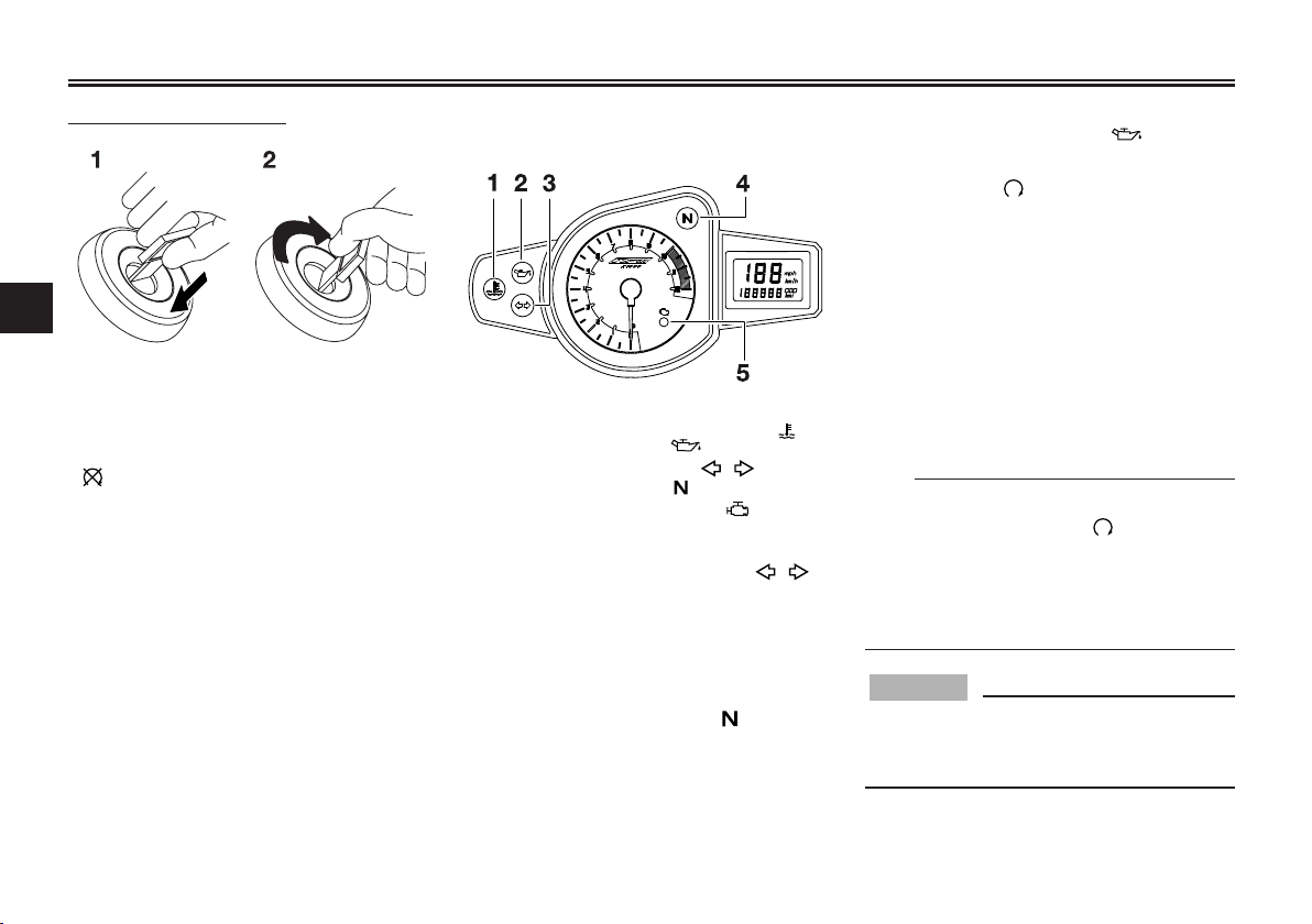
Indicator and warning lights
1. Coolant temperature warning light “ ”
2. Oil level warning light “ ”
3. Turn signal indicator light “ ”
4. Neutral indicator light “ ”
5. Engine trouble warning light “ ”
EAU11020
Turn signal indicator light “ ”
This indicator light flashes when the
turn signal switch is pushed to the left
or right.
EAU11060
Neutral indicator light “ ”
This indicator light comes on when
the transmission is in the neutral position.
EAUM1062
Oil level warning light “ ”
This warning light comes on when the
key is in the “ ” position or if the oil
level in the 2-stroke engine oil tank is
low during operation. If the warning
light comes on during operation, stop
immediately and fill the oil tank with
2-stroke engine oil of either JASO
grade “FC” or ISO grades “EG-C” or
“EG-D”. The warning light should go
off after the 2-stroke engine oil tank
has been refilled.
TIP
If the warning light does not come on
when the key is in the “ ” position or
does not go off after the 2-stroke
engine oil tank has been refilled, have
an Yamaha dealer check the electrical
circuit.
ECA16291
NOTICE
Do not operate the vehicle until you
know that the engine oil level is sufficient.
3-2
INSTRUMENT AND CONTROL FUNCTIONS
EAU11444
Coolant temperature warning light
“”
This warning light comes on if the
engine overheats. If this occurs, stop
the engine immediately and allow the
engine to cool.
The electrical circuit of the warning light
can be checked by turning the key to
“ ”. The warning light should come
on for a few seconds, and then go off.
If the warning light does not come on
initially when the key is turned to “ ”,
or if the warning light remains on,
have a Yamaha dealer check the
electrical circuit.
ECA10021
NOTICE
Do not continue to operate the
engine if it is overheating.
TIP
● For radiator-fan-equipped vehi-
cles, the radiator fan(s) automatically switch on or off according to
the coolant temperature in the
radiator.
● If the engine overheats, see page
6-37 for further instructions.
EAUS1540
Engine trouble warning light “ ”
This warning light flashes if a problem
is detected in the electrical circuit
monitoring the engine. If this occurs,
have a Yamaha dealer check the selfdiagnosis system.
The electrical circuit of the warning
light can be checked by turning the
key to “ ”. If the warning light does
not come on for a few seconds, then
go off, have a Yamaha dealer check
the electrical circuit.
EAU11621
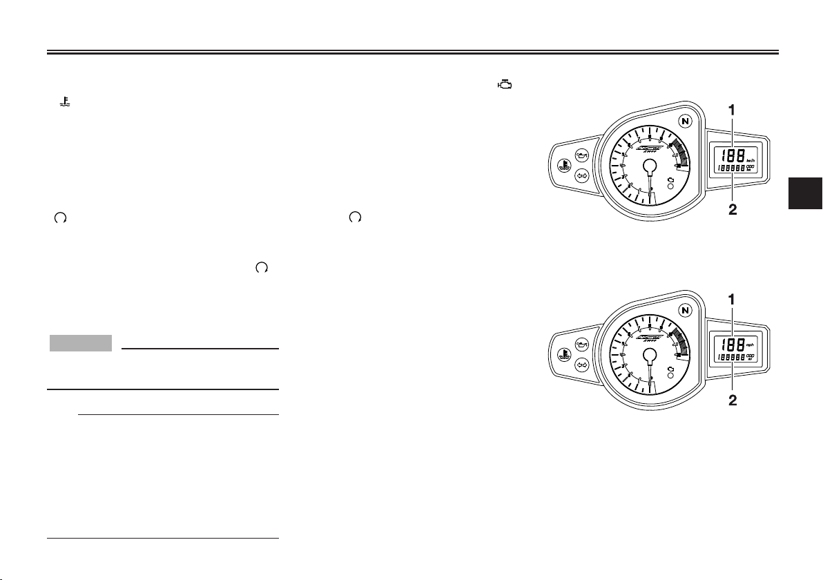
Speedometer unit
3
1. Speedometer
2. Odometer
UK ONLY
1. Speedometer
2. Odometer
The speedometer unit is equipped
with a speedometer and an odometer.
The speedometer shows riding speed. The odometer shows the total distance traveled.
3-3
INSTRUMENT AND CONTROL FUNCTIONS
Tachometer
3
1. Tachometer
The electric tachometer allows the
rider to monitor the engine speed and
keep it within the ideal power range.
NOTICE
Do not operate the engine in the
tachometer red zone.
Red zone: 10000 r/min and above
EAU11851
ECA10031
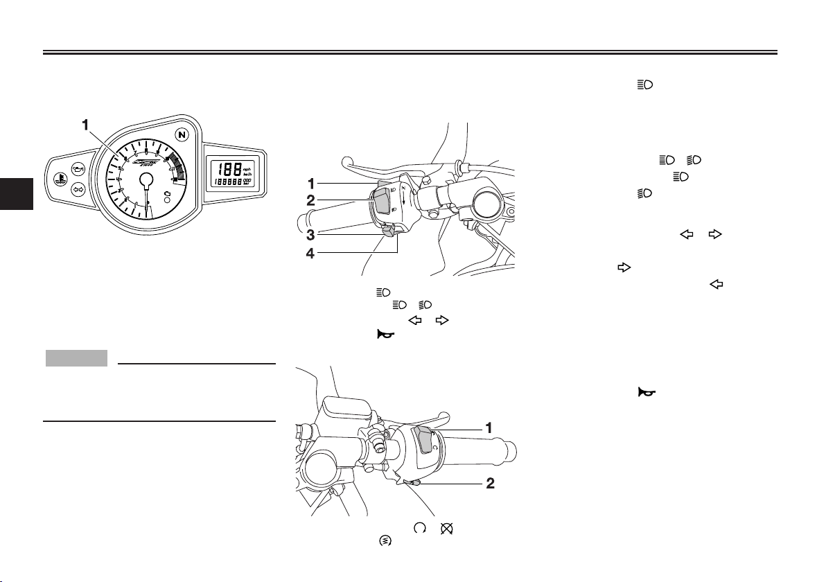
Handlebar switches
Left
1. Pass switch “ ”
2. Dimmer switch “ / ”
3. Turn signal switch “ / ”
4. Horn switch “ ”
Right
EAU12348
EAU12360
Pass switch “ ”
Press this switch to flash the headlight.
EAU12400
Dimmer switch “ / ”
Set this switch to “ ” for the high
beam and to “ ” for the low beam.
EAU12460
Turn signal switch “ / ”
To signal a right-hand turn, push this
switch to “ ”. To signal a left-hand
turn, push this switch to “ ”. When
released, the switch returns to the
center position. To cancel the turn
signal lights, push the switch in after it
has returned to the center position.
EAU12500
Horn switch “ ”
Press this switch to sound the horn.
1. Engine stop switch “ / ”
2. Start switch “ ”
3-4
INSTRUMENT AND CONTROL FUNCTIONS
EAU12660
Engine stop switch “ / ”
Set this switch to “ ” before starting the engine. Set this switch to
“ ” to stop the engine in case of an
emergency, such as when the vehicle
overturns or when the throttle cable is
stuck.
EAU12711
Start switch “ ”
Push this switch to crank the engine
with the starter. See page 5-1 for starting instructions prior to starting the
engine.
EAU31640
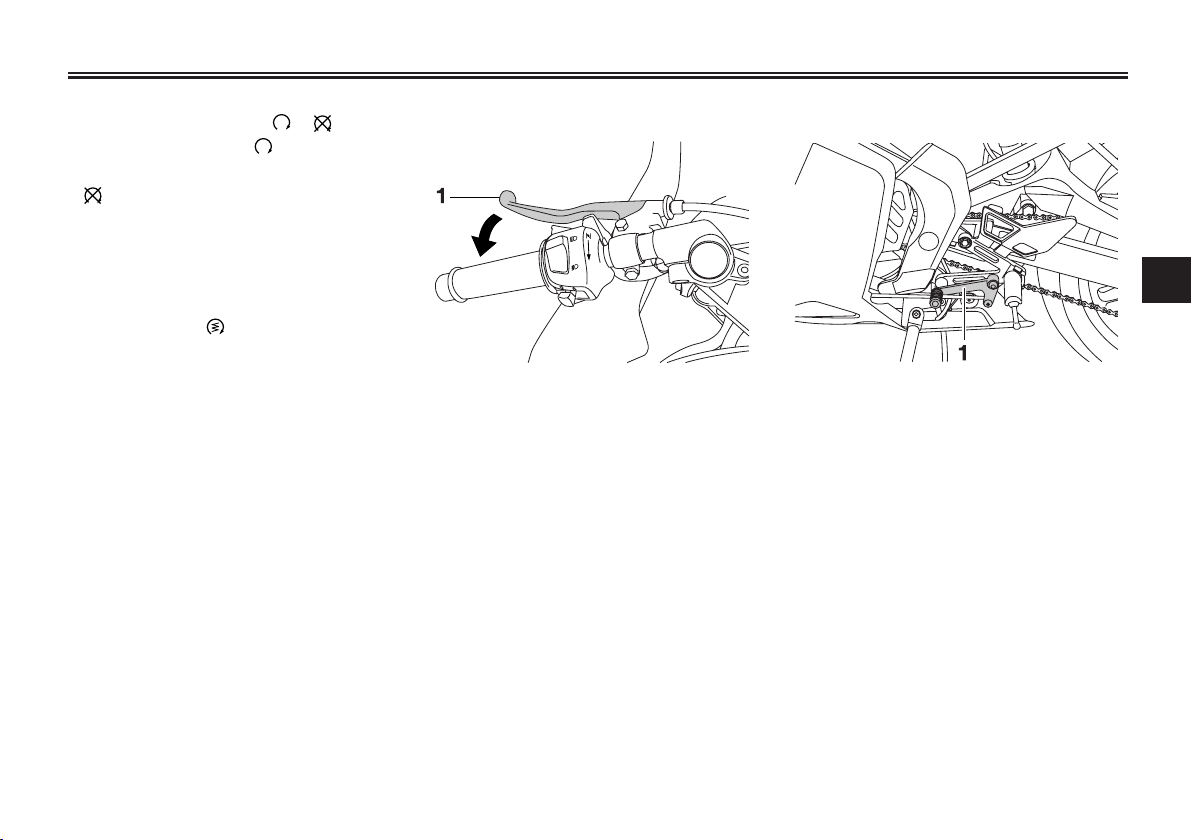
Clutch lever
1. Clutch lever
The clutch lever is located at the left
handlebar grip. To disengage the
clutch, pull the lever toward the handlebar grip. To engage the clutch, release the lever. The lever should be
pulled rapidly and released slowly for
smooth clutch operation.
The clutch lever is equipped with a
clutch switch, which is part of the
starting circuit cut-off system. (See
page 3-13).
EAU12870
Shift pedal
3
1. Shift pedal
The shift pedal is located on the left
side of the engine and is used in combination with the clutch lever when
shifting the gears of the 6-speed
constant-mesh transmission equipped on this motorcycle.
3-5
INSTRUMENT AND CONTROL FUNCTIONS
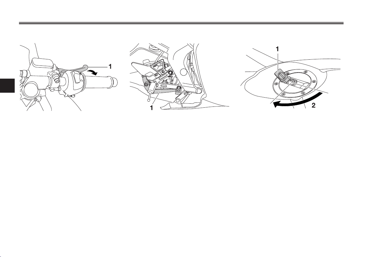
Brake lever
3
1. Brake lever
The brake lever is located at the right
handlebar grip. To apply the front brake, pull the lever toward the handlebar grip.
EAU12890
EAU12941
Brake pedal
1. Brake pedal
The brake pedal is on the right side of
the motorcycle. To apply the rear brake, press down on the brake pedal.
EAU13074
Fuel tank cap
1. Fuel tank cap lock cover
2. Unlock.
To open the fuel tank cap
Open the fuel tank cap lock cover,
insert the key into the lock, and then
turn it 1/4 turn clockwise. The lock will
be released and the fuel tank cap can
be opened.
3-6
INSTRUMENT AND CONTROL FUNCTIONS
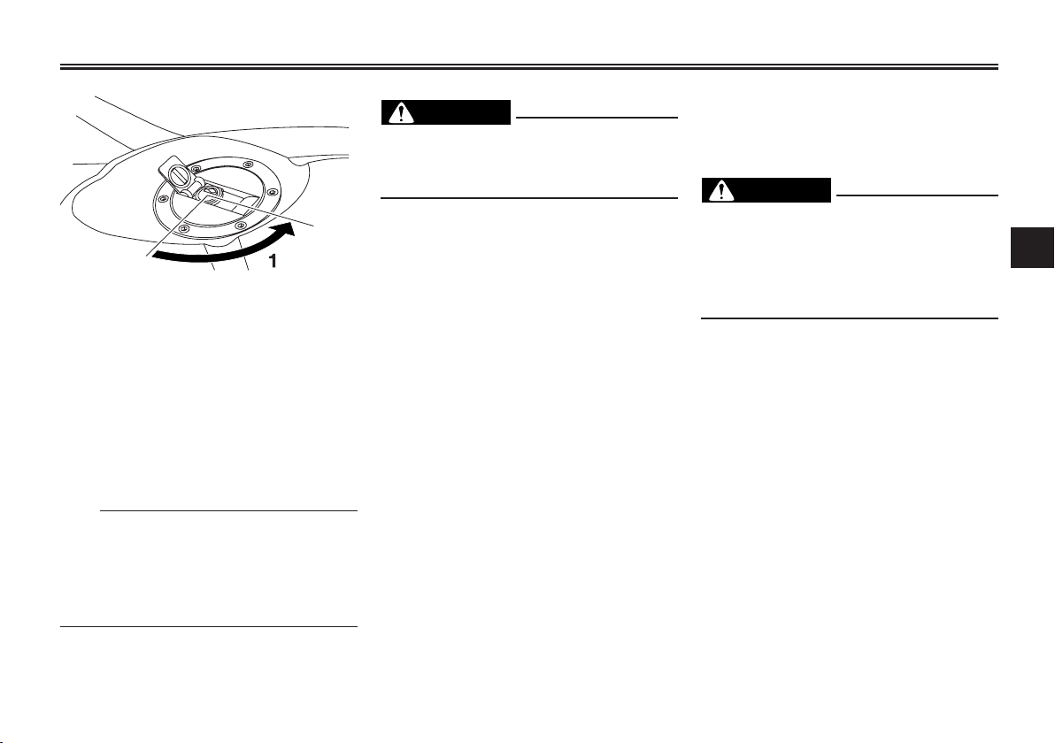
1. Lock.
To close the fuel tank cap
1. Push the fuel tank cap into position with the key inserted in the
lock.
2. Turn the key counterclockwise to
the original position, remove it,
and then close the lock cover.
TIP
The fuel tank cap cannot be closed
unless the key is in the lock. In addition, the key cannot be removed if the
cap is not properly closed and locked.
EWA11091
WARNING
Make sure that the fuel tank cap is
properly closed after filling fuel.
Leaking fuel is a fire hazard.
EAU13212
Fuel
Make sure there is sufficient gasoline
in the tank.
WARNING
Gasoline and gasoline vapors are
extremely flammable. To avoid fires
and explosions and to reduce the
risk of injury when refueling, follow
these instructions.
1. Before refueling, turn off the engine and be sure that no one is sitting on the vehicle. Never refuel
while smoking, or while in the
vicinity of sparks, open flames, or
other sources of ignition such as
the pilot lights of water heaters
and clothes dryers.
2. Do not overfill the fuel tank. Stop
filling when the fuel reaches the
bottom of the filler tube. Because
fuel expands when it heats up,
heat from the engine or the sun
can cause fuel to spill out of the
fuel tank.
EWA10881
3
3-7

INSTRUMENT AND CONTROL FUNCTIONS
3
1. Fuel tank filler tube
2. Fuel level
3. Wipe up any spilled fuel imme-
diately. NOTICE: Immediately
wipe off spilled fuel with a clean, dry, soft cloth, since fuel
may deteriorate painted surfaces or plastic parts. [ECA10071]
4. Be sure to securely close the fuel
tank cap.
WARNING
Gasoline is poisonous and can cause injury or death. Handle gasoline
with care. Never siphon gasoline by
mouth. If you should swallow some
gasoline or inhale a lot of gasoline
vapor, or get some gasoline in your
EWA15151
eyes, see your doctor immediately.
If gasoline spills on your skin, wash
with soap and water. If gasoline
spills on your clothing, change your
clothes.
EAU13270
Recommended fuel:
REGULAR UNLEADED
GASOLINE ONLY
Fuel tank capacity:
13.8 L (3.65 US gal, 3.04 Imp.gal)
Fuel reserve amount:
2.2 L (0.58 US gal, 0.48 Imp.gal)
Your Yamaha engine has been designed to use regular unleaded gasoline
with a research octane number of 91
or higher. If knocking (or pinging)
occurs, use a gasoline of a different
brand or premium unleaded fuel. Use
of unleaded fuel will extend spark
plug life and reduce maintenance
costs.
EAUB1300
Fuel tank breather/overflow
hose
1. Fuel tank breather/overflow hose
Before operating the motorcycle:
● Check the fuel tank breather/
overflow hose connection.
● Check the fuel tank breather/
overflow hose for cracks or
damage, and replace it if damaged.
● Make sure that the end of the fuel
tank breather/overflow hose is
not blocked, and clean it if
necessary.
● Make sure that the end of the fuel
tank breather/overflow hose is
positioned inside of the clamp.
3-8
INSTRUMENT AND CONTROL FUNCTIONS
EAU13433
Catalytic converter
This model is equipped with a catalytic converter in the exhaust system.
WARNING
The exhaust system is hot after
operation. To prevent a fire hazard
or burns:
● Do not park the vehicle near
possible fire hazards such as
grass or other materials that
easily burn.
● Park the vehicle in a place
where pedestrians or children
are not likely to touch the hot
exhaust system.
● Make sure that the exhaust
system has cooled down before doing any maintenance
work.
● Do not allow the engine to idle
more than a few minutes. Long
idling can cause a build-up of
heat.
EWA10862
ECA10701
NOTICE
Use only unleaded gasoline. The
use of leaded gasoline will cause
unrepairable damage to the catalytic converter.
EAUS1550
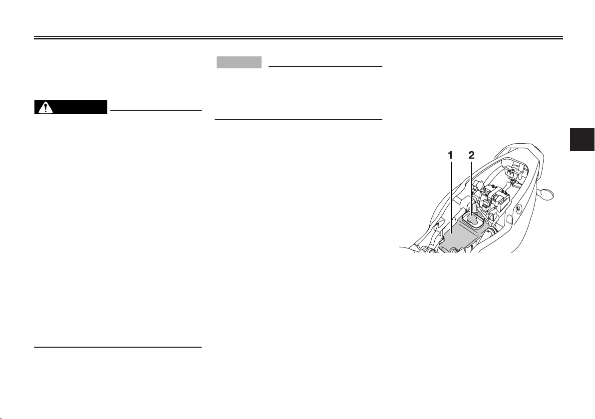
2-stroke engine oil
Make sure that there is sufficient 2stroke engine oil in the oil tank. Add
the recommended 2-stroke engine oil
as necessary.
The 2-stroke engine oil tank is located
under the seat. (See page 3-11).
1. 2-stroke engine oil tank
2. 2-stroke engine oil tank cap
1. Remove the 2-stroke engine oil
tank cap by pulling it off.
3
3-9
INSTRUMENT AND CONTROL FUNCTIONS
3
2. Install the 2-stroke engine oil tank
cap by pushing it into the oil tank
opening.
TIP
Make sure that the 2-stroke engine oil
tank cap is properly installed before
riding the vehicle.
EAU13561
Fuel cock
The fuel cock supplies fuel from the
tank to the carburetor while filtering it
also.
The fuel cock has three positions:
OFF
1. Pointed end positioned over “OFF”
With the lever in this position, fuel will
not flow. Always return the lever to
this position when the engine is not
running.
ON
1. Pointed end positioned over “ON”
With the lever in this position, fuel
flows to the carburetor. Normal riding
is done with the lever in this position.
RES
Recommended oil:
See page 8-1
Oil quantity:
1.40 L (1.48 US qt, 1.23 Imp.qt)
1. Pointed end positioned over “RES”
3-10
INSTRUMENT AND CONTROL FUNCTIONS
This indicates reserve. If you run out
of fuel while riding, move the lever to
this position. Fill the tank at the first
opportunity. Be sure to set the lever
back to “ON” after refueling!
EAU13590
Starter (choke) lever “ ”
1. Starter (choke) lever “ ”
Starting a cold engine requires a
richer air-fuel mixture, which is supplied by the starter (choke).
Move the lever in direction (a) to turn
on the starter (choke).
Move the lever in direction (b) to turn
off the starter (choke).
EAU13900
Seat
To remove the seat
1. Insert the key into the seat lock,
and then turn it as shown.
3
1. Seat lock
2. Open.
2. Pull the seat off.
To install the seat
1. Insert the projection on the front
of the seat into the seat holder as
shown.
3-11

INSTRUMENT AND CONTROL FUNCTIONS
3
1. Projection
2. Seat holder
2. Push the rear of the seat down to
lock it in place.
3. Remove the key.
TIP
Make sure that the seat is properly
secured before riding.
EAUM1941
Anti-theft device housing
The anti-theft device housing, located
in the storage compartment under the
seat, is designed to hold a genuine
Yamaha CYCLELOK. (See page 3-11
for seat opening and closing procedures.) When placing a CYCLELOK in
the storage compartment, securely
fasten it with the straps. When the
CYCLELOK is not in the storage compartment, be sure to secure the
straps to prevent losing them.
TIP
Some U-LOCKS cannot fit into the
housing due to their size or shape.
EAU39671
Rear view mirrors
The rear view mirrors of this vehicle
can be folded forward or backward
for parking in narrow spaces. Fold the
mirrors back to their original position
before riding.
EWA14371
WARNING
Be sure to fold the rear view
mirrors back to their original position before riding.
3-12
INSTRUMENT AND CONTROL FUNCTIONS
EAU15301
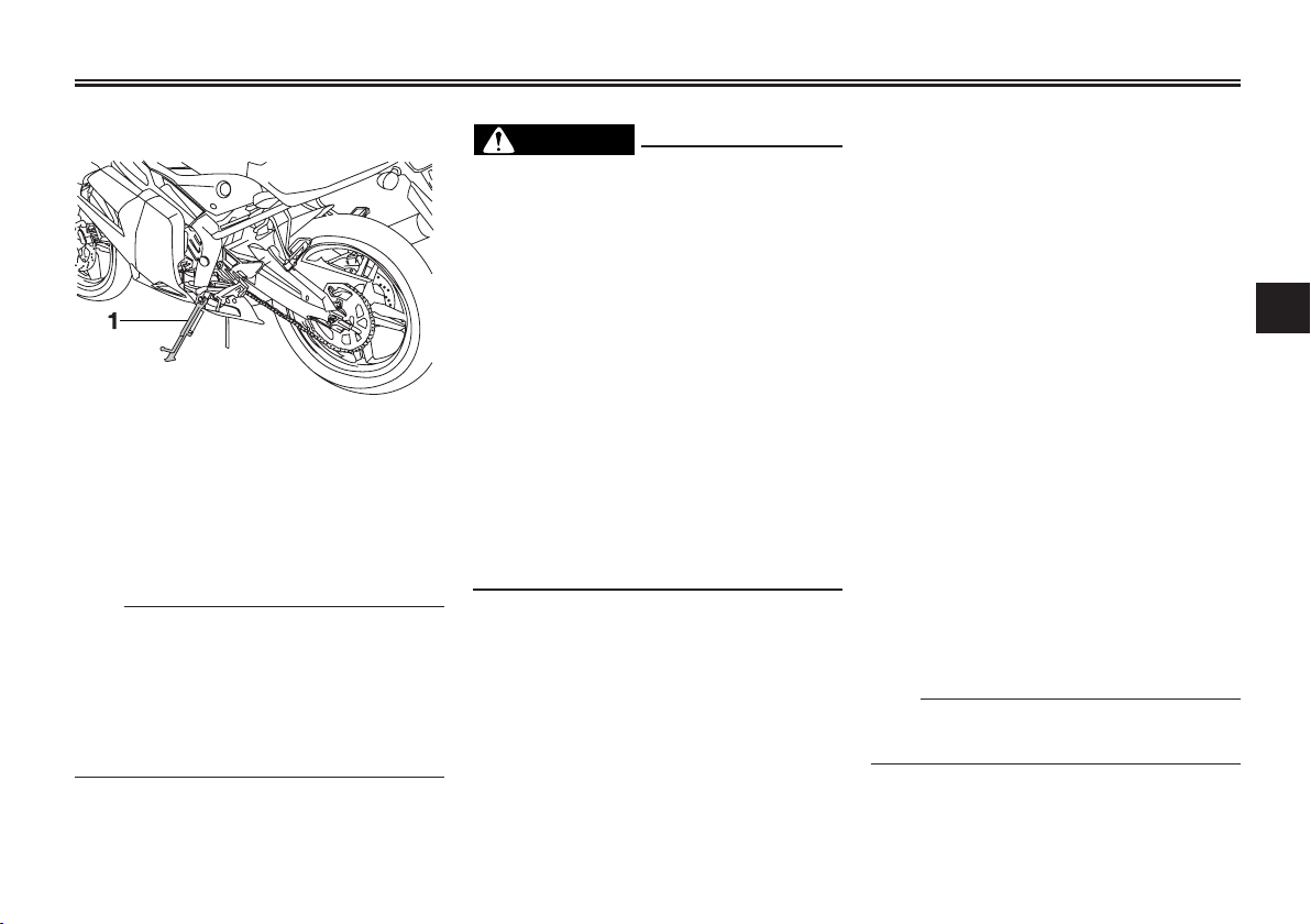
Sidestand
1. Sidestand
The sidestand is located on the left
side of the frame. Raise the sidestand
or lower it with your foot while holding
the vehicle upright.
TIP
The built-in sidestand switch is part of
the ignition circuit cut-off system,
which cuts the ignition in certain
situations. (See further down for an
explanation of the ignition circuit cutoff system.)
EWA10240
WARNING
The vehicle must not be ridden with
the sidestand down, or if the sidestand cannot be properly moved up
(or does not stay up), otherwise the
sidestand could contact the ground
and distract the operator, resulting
in a possible loss of control. Yamaha’s ignition circuit cut-off system
has been designed to assist the
operator in fulfilling the responsibility of raising the sidestand before
starting off. Therefore, check this
system regularly as described
below and have a Yamaha dealer
repair it if it does not function properly.
EAU15314
Ignition circuit cut-off system
The ignition circuit cut-off system
(comprising the sidestand switch,
clutch switch and neutral switch) has
the following functions.
● It prevents starting when the
transmission is in gear and the
sidestand is up, but the clutch
lever is not pulled.
● It prevents starting when the
transmission is in gear and the
clutch lever is pulled, but the
sidestand is still down.
● It cuts the running engine when
the transmission is in gear and
the sidestand is moved down.
Periodically check the operation of
the ignition circuit cut-off system
according to the following procedure.
TIP
This check is most reliable if performed with a warmed-up engine.
3
3-13
 Loading...