


OWNER’S MANUAL
TW200
5FY-28199-EX

INTRODUCTION
EAU00000
Congratulations on your purchase of the Yamaha TW200. This model is the result of Yamaha’s
vast experience in the production of fine sporting, touring, and pacesetting racing machines. It
represents the high degree of craftsmanship and reliability that have made Yamaha a leader in
these fields.
This manual will give you an understanding of the operation, inspection, and basic maintenance of this motorcycle. If you have any questions about the operation or maintenance of
your motorcycle, please consult a Yamaha dealer.
1
2
4
5
6
7
8
9
IMPORTANT MANUAL INFORMATION
Particularly important information is distinguished in this manual by the following notations:
EAU00005
1
Q
2
3
4
5
6
7
8
9
w
cC
NOTE:
NOTE:
8 This manual should be considered a permanent part of this motorcycle and should
8 Yamaha continually seeks advancements in product design and quality. Therefore,
The Safety Alert Symbol means ATTENTION! BECOME ALERT! YOUR SAFETY
IS INVOLVED!
Failure to follow WARNING instructions could result in severe injury or death to the
motorcycle operator, a bystander or a person inspecting or repairing the motorcycle.
A CAUTION indicates special precautions that must be taken to avoid damage to
the motorcycle.
A NOTE provides key information to make procedures easier or clearer.
remain with it even if the motorcycle is subsequently sold.
while this manual contains the most current product information available at the time
of printing, there may be minor discrepancies between your motorcycle and this manual. If there is any question concerning this manual, please consult your Yamaha dealer.

IMPORTANT MANUAL INFORMATION
EW000002
w
PLEASE READ THIS MANUAL CAREFULLY AND COMPLETELY BEFORE OPERATING THIS
MOTORCYCLE.
1
2
4
5
6
7
8
9
1
2
3
4
5
6
EAU00008
TW200
7
OWNER’S MANUAL
©1997 by Yamaha Motor Co., Ltd.
8
1st Edition, November 1997
All rights reserved. Any reprinting or
9
unauthorized use without the written
permission of Yamaha Motor Co., Ltd.
is expressly prohibited.
Printed in Japan
EAU00009
TABLE OF CONTENTS
GIVE SAFETY THE RIGHT OF WAY ..................1-1
1
DESCRIPTION .....................................................2-1
2
Left view............................................................2-1
Right view.........................................................2-2
Controls/Instruments .......................................2-3
INSTRUMENT AND CONTROL
3
FUNCTIONS........................................................3-1
Main switch/Steering lock ...............................3-1
Indicator lights..................................................3-2
Speedometer....................................................3-2
Handlebar switches..........................................3-3
Clutch lever.......................................................3-4
Shift pedal.........................................................3-4
Front brake lever ..............................................3-5
Rear brake pedal ..............................................3-5
Fuel tank cap.....................................................3-5
Fuel....................................................................3-6
Fuel cock ...........................................................3-7
Starter (choke) “1”.........................................3-8
Kick starter........................................................3-8
Seat ...................................................................3-9
Helmet holder...................................................3-9
Rear shock absorber ......................................3-10
Rear carrier .....................................................3-10
Sidestand........................................................3-10
Sidestand/clutch switch operation check.....3-11
PRE-OPERATION CHECKS.................................4-1
4
Pre-operation check list ...................................4-1
OPERATION AND IMPORTANT RIDING
5
POINTS................................................................5-1
Starting and warming up a cold engine.........5-1
Starting a warm engine...................................5-4
Shifting..............................................................5-4
Engine break-in ................................................5-5
Parking ..............................................................5-6
PERIODIC MAINTENANCE AND MINOR
6
REPAIR ................................................................6-1
Tool kit ..............................................................6-1
Periodic maintenance and lubrication............6-3
Cowling and panel removal and
installation ........................................................6-6
Cowling A .........................................................6-6
Panel A..............................................................6-7
Panel B ..............................................................6-7
Spark plug inspection......................................6-7
Engine oil..........................................................6-8
Air filter ...........................................................6-12
1
2
3
4
5
6
7
8
9

TABLE OF CONTENTS
Carburetor adjustment ..................................6-13
Idle speed adjustment ...................................6-13
1
2
3
4
5
6
7
8
9
Throttle cable free play inspection ...............6-14
Cam chain adjustment...................................6-14
Valve clearance adjustment ..........................6-14
Tires.................................................................6-15
Wheels ............................................................6-17
Clutch lever free play adjustment.................6-18
Front brake lever free play adjustment ........6-18
Rear brake pedal height and free play
adjustment......................................................6-19
Brake light switch adjustment.......................6-20
Checking the brake shoes..............................6-21
Drive chain slack check..................................6-21
Drive chain slack adjustment ........................6-22
Drive chain lubrication...................................6-23
Cable inspection and lubrication ..................6-24
Throttle cable and grip lubrication ...............6-24
Brake and shift pedal lubrication..................6-24
Brake and clutch lever lubrication ................6-25
Sidestand lubrication.....................................6-25
Rear suspension lubrication..........................6-25
Front fork inspection......................................6-26
Steering inspection........................................6-26
Wheel bearings ..............................................6-27
Battery.............................................................6-27
Fuse replacement...........................................6-29
Headlight bulb replacement..........................6-30
Supporting the motorcycle ...........................6-31
Front wheel removal......................................6-31
Front wheel installation.................................6-32
Rear wheel removal.......................................6-33
Rear wheel installation ..................................6-33
Troubleshooting.............................................6-34
Troubleshooting chart ...................................6-35
CLEANING AND STORAGE ...............................7-1
7
Cleaning............................................................7-1
Storage..............................................................7-2
SPECIFICATIONS................................................8-1
8
How to use the conversion table ....................8-4
CONSUMER INFORMATION .............................9-1
9
Identification numbers record.........................9-1
Key identification number ...............................9-1
Vehicle identification number .........................9-1
Model label.......................................................9-2

EAU00021
Q GIVE SAFETY THE RIGHT OF WAY
Motorcycles are fascinating vehicles, which can give you an unsurpassed feeling of power and
freedom. However, they also impose certain limits, which you must accept; even the best
motorcycle does not ignore the laws of physics.
Regular care and maintenance are essential for preserving your motorcycle’s value and operating condition. Moreover, what is true for the motorcycle is also true for the rider: good performance depends on being in good shape. Riding under the influence of medication, drugs and
alcohol is, of course, out of the question. Motorcycle riders more than car drivers must always
be at their mental and physical best. Under the influence of even small amounts of alcohol,
there is a tendency to take dangerous risks.
1
2
3
4
Protective clothing is as essential for the motorcycle rider as seat belts are for car drivers and
passengers. Always wear a complete motorcycle suit (whether made of leather or tear-resistant
synthetic materials with protectors), sturdy boots, motorcycle gloves and a properly fitting helmet. Optimum protective wear, however, should not encourage carelessness. Though full-coverage helmets and suits, in particular, create an illusion of total safety and protection, motorcyclists will always be vulnerable. Riders who lack critical self-control run the risk of going too
fast and are apt to take chances. This is even more dangerous in wet weather. The good motorcyclist rides safely, predictably and defensively avoiding all dangers, including those caused by
others.
Enjoy your ride!
1-1
5
6
7
8
9
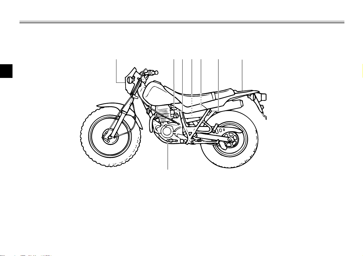
DESCRIPTION
1 234 56 7
8
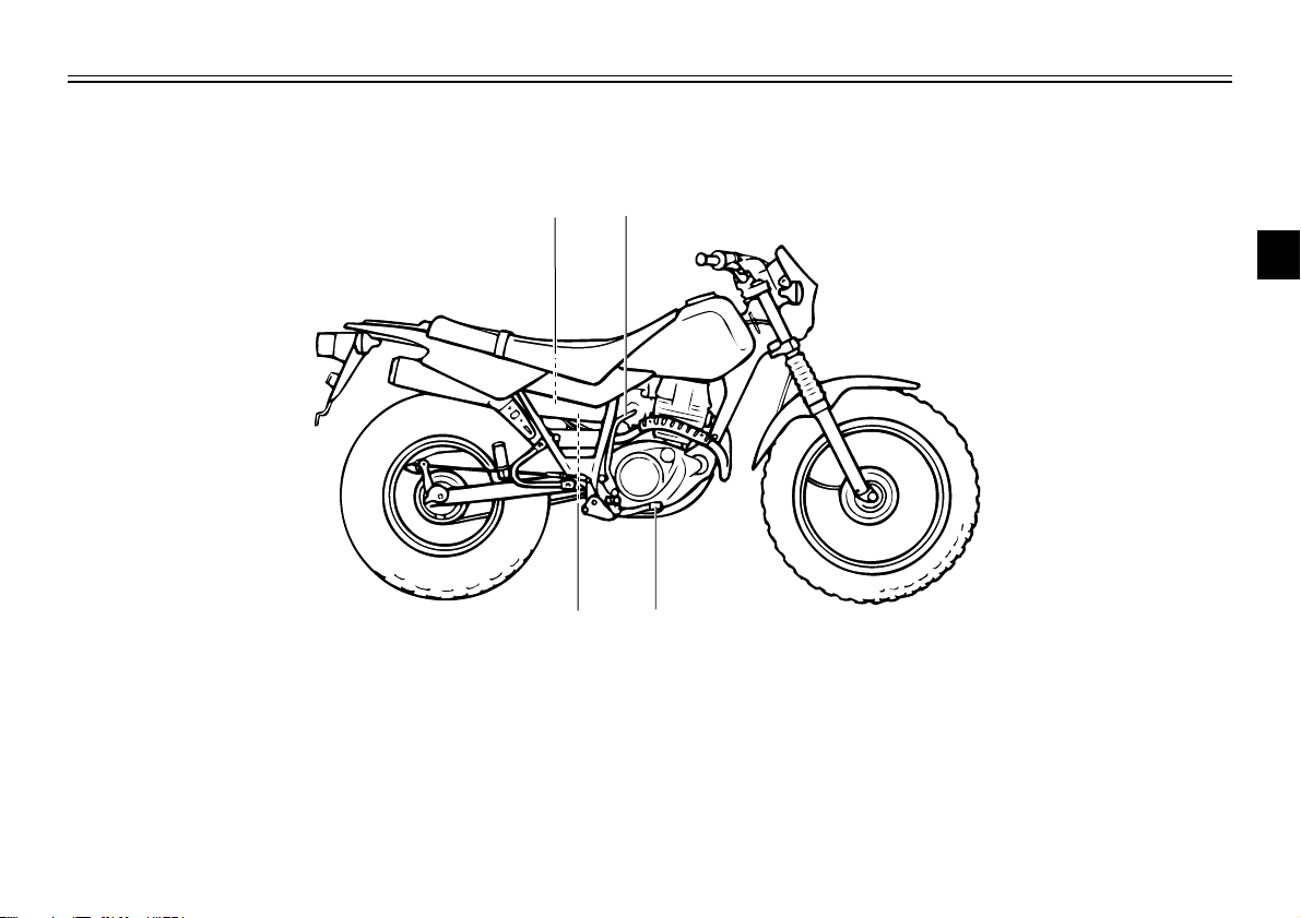
Left view
1
2
3
4
EAU00026
5
6
7
8
9
1. Headlight (page 6-30)
2. Fuel cock (page 3-7)
3. Starter(choke) “1“ (page 3-8)
4. Air filter (page 6-12)
5. Battery (page 6-27)
6. Helmet holder (page 3-9)
7. Rear carrier (page 3-10)
8. Shift pedal (page 3-4)
2-1
910
11
12
Right view
DESCRIPTION
1
2
3
4
9. Fuse (page 3-6)
10. Kick starter (page 3-8)
11. Rear brake pedal (page 3-5)
12. Tool kit (page 6-1)
5
6
7
8
9
2-2
DESCRIPTION
13 14 15 16 17
18
19
20
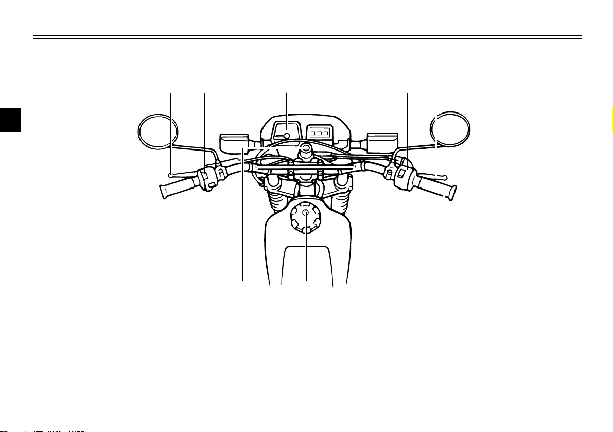
Controls/Instruments
1
2
3
4
5
6
7
8
9
13. Clutch lever (page 3-4, 6-18)
14. Left handlebar switches (page 3-3)
15. Speedometer (page 3-2)
16. Right handlebar switches (page 3-3)
17. Front brake lever (page 3-5, 6-18)
18. Throttle grip (page 6-14, 6-24)
19. Fuel tank cap (page 3-5)
20. Main switch (page 3-1)
2-3
LOCK
OFF
ON
EAU00027
INSTRUMENT AND CONTROL FUNCTIONS
EAU00029
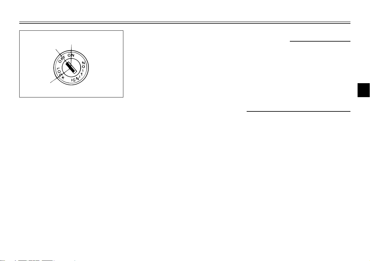
Main switch/Steering lock
The main switch controls the ignition and lighting systems. Its operation is described below.
EAU00032
ON:
All electrical circuits are switched
on, and the headlight, meter light,
taillight and front position lights
come on. The engine can be started. The key cannot be removed in
this position.
EAU00038
OFF:
All electrical circuits are switched
off. The key can be removed in this
position.
EAU00042
LOCK:
The steering is locked in this position and all electrical circuits are
switched off.
The key can be removed in this
position.
To lock the steering, turn the handlebars all the way to the left. With
the key at “OFF”, push it into the
main switch and release it, turn it
counterclockwise to “LOCK” and
remove it.
To release the lock, turn the key to
“OFF”.
EW000016
w
Never turn the key to “OFF” or
“LOCK” when the motorcycle is
moving. The electrical circuits will
be switched off which may result
in loss of control or an accident. Be
sure the motorcycle is stopped
before turning the key to “OFF” or
“LOCK”.
1
2
3
4
5
6
7
8
9
3-1
123
INSTRUMENT AND CONTROL FUNCTIONS
1
2
High beam indicator light “HIGH
BEAM”
1
2
3
This indicator comes on when the
headlight high beam is used.
EAU00064
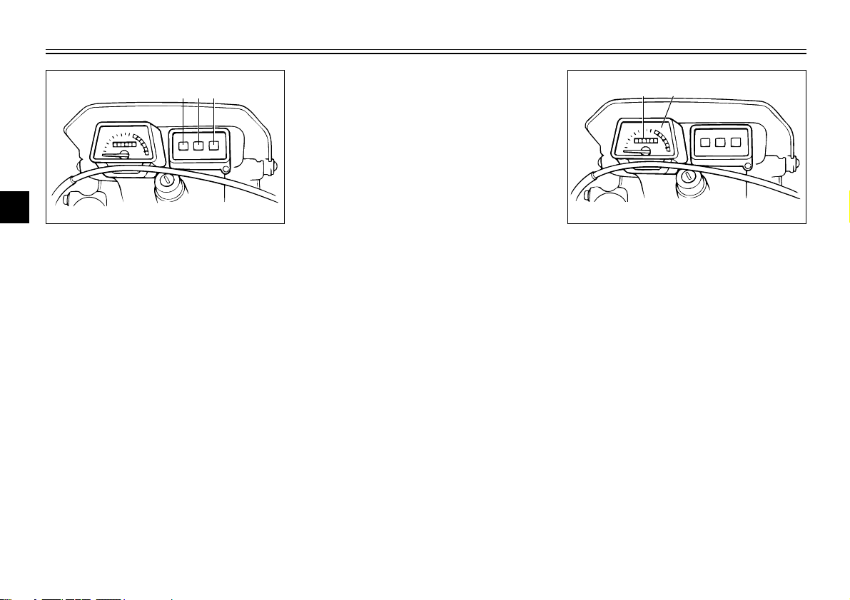
1. Turn indicator light “TURN”
4
2. High beam indicator light
“HIGH BEAM”
3. Neutral indicator light “NEUTRAL”
5
Indicator lights
6
Turn indicator light “TURN”
This indicator flashes when the
7
turn switch is moved to the left or
right.
8
9
Neutral indicator light “NEUTRAL”
This indicator comes on when the
transmission is in neutral.
EAU00056
EAU00059
EAU00062
1. Speedometer
2. Odometer
EAU00098
Speedometer
The speedometer shows riding
speed.
This speedometer is equipped with
an odometer.
3-2
INSTRUMENT AND CONTROL FUNCTIONS
1
2
3
1
2
EAU00130
Horn switch “HORN”
Press the switch to sound the horn.
1
2
3
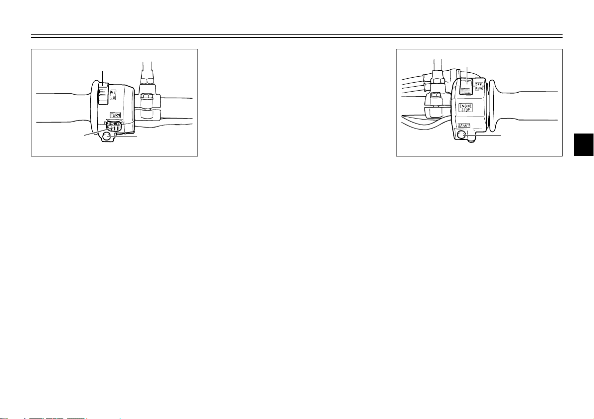
1. Dimmer switch “LIGHTS”
2. Turn signal switch “TURN”
3. Horn switch “HORN”
EAU00118
Handlebar switches
EAU00122
Dimmer switch “LIGHTS”
Turn the switch to “HI” for the high
beam and to “LO” for the low
beam.
EAU00128
Turn signal switch “TURN”
This is a three-position switch. The
center position is off.
Turn to “L” to turn on the left
flasher, and to “R” for the right
flasher. Be sure to turn the switch
off after completing a turn.
3-3
1. Engine stop switch “ENGINE STOP”
2. Start switch “START”
EAU00137
Engine stop switch “ENGINE
STOP”
The engine stop switch is a safety
device for use in an emergency
such as when the motorcycle overturns or if trouble occurs in the
throttle system. Turn the switch to
“RUN” to start the engine. In case
of emergency, turn the switch to
“OFF” to stop the engine.
4
5
6
7
8
9
INSTRUMENT AND CONTROL FUNCTIONS
1
N
5
4
3
2
1
EAU00141
Start switch “START”
The starter motor cranks the
engine when pushing the start
1
switch.
2
cC
3
See starting instructions prior to
starting the engine.
4
5
6
7
8
9
EC000005
EAU00152
Clutch lever
The clutch lever is located on the
left handlebar, and the ignition circuit cut-off system is incorporated
in the clutch lever holder. Pull the
clutch lever to the handlebar to disengage the clutch, and release the
lever to engage the clutch. The
lever should be pulled rapidly and
released slowly for smooth clutch
operation. (Refer to the engine
starting procedures for a description of the ignition circuit cut-off
system.)
3-4
N. Neutral
1. Shift pedal
EAU00157
Shift pedal
This motorcycle is equipped with a
constant-mesh 5-speed transmission.
The shift pedal is located on the
left side of the engine and is used
in combination with the clutch
when shifting.
INSTRUMENT AND CONTROL FUNCTIONS
1
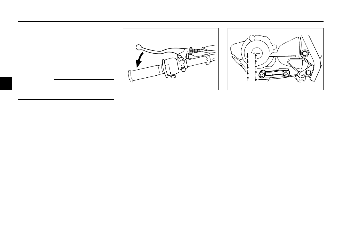
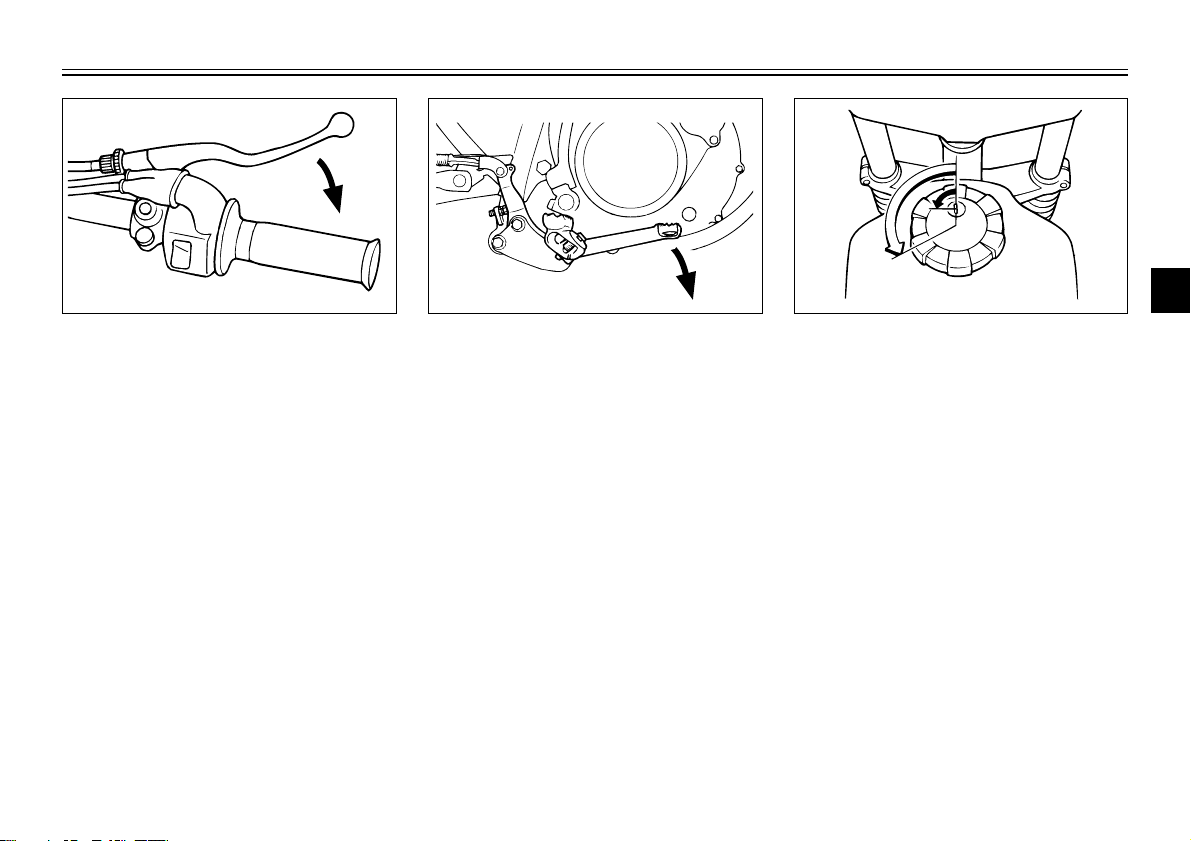
EAU00158
Front brake lever
The front brake lever is located on
the right handlebar. Pull it toward
the handlebar to apply the front
brake.
EAU00162
Rear brake pedal
The rear brake pedal is on the right
side of the motorcycle. Press down
on the brake pedal to apply the
rear brake.
1
2
1. Unlock
2. Open
EAU00177
Fuel tank cap
TO OPEN:
Insert the key and turn it 1/4 turn
counterclockwise. Turn the cap 1/3
turn counterclockwise and remove
it from the tank.
TO CLOSE:
Put the cap in the filler neck and
turn it 1/3 turn clockwise. Lock the
cap by turning the key 1/4 turn
clockwise, and remove the key.
2
3
4
5
6
7
8
9
3-5
1
2
INSTRUMENT AND CONTROL FUNCTIONS
NOTE:
The tank cap cannot be reinstalled
unless it is unlocked. The key must
1
remain in the cap until the cap is
properly installed and locked onto
2
the fuel tank.
3
w
4
Be sure the cap is properly
installed and locked in place
before riding the motorcycle.
5
6
7
8
9
EAU00185
cC
Always wipe off spilled fuel immediately with a dry and clean soft
cloth. Fuel may deteriorate painted
surfaces or plastic parts.
EW000023
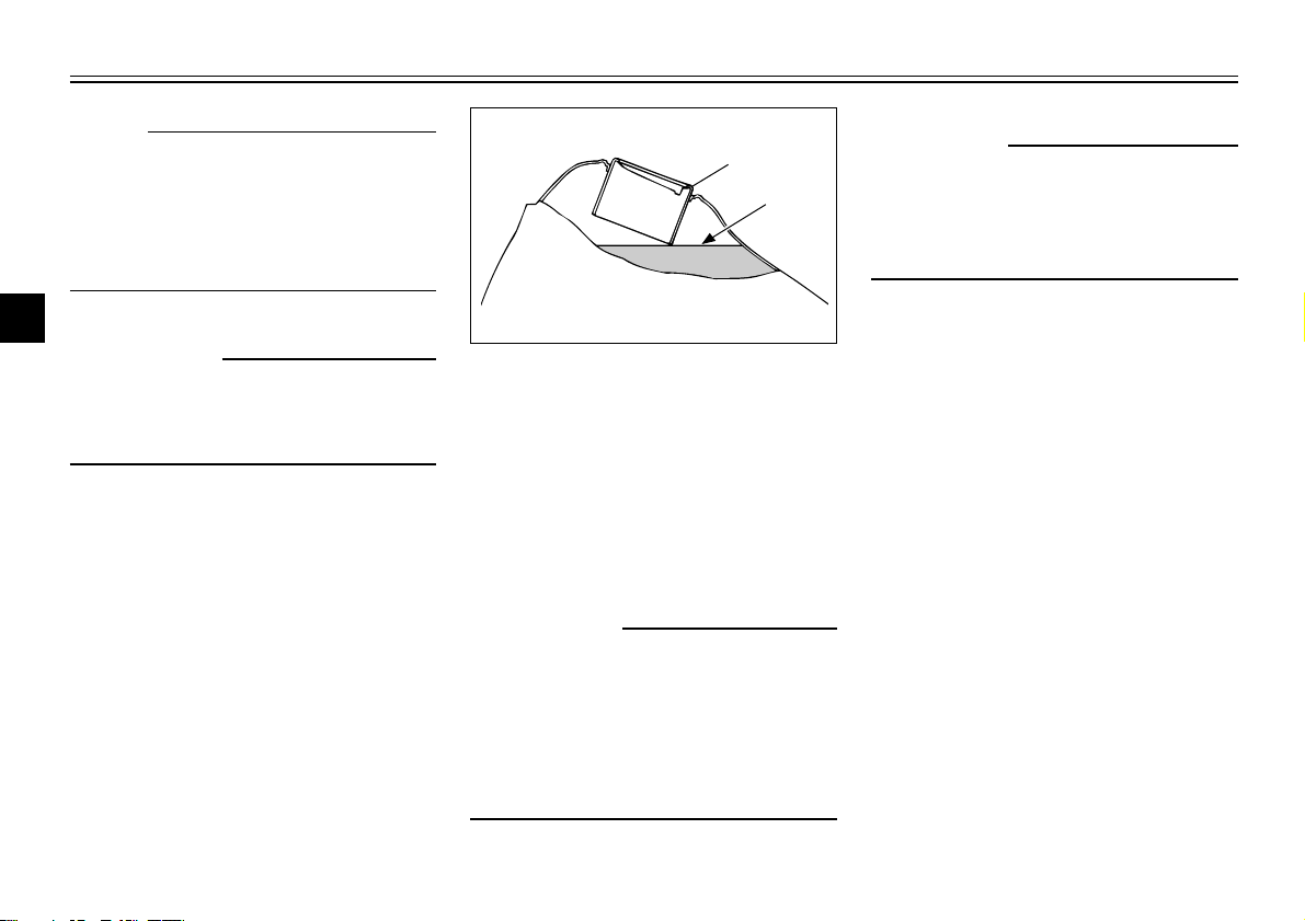
1. Filler tube
2. Fuel level
EAU01183
Fuel
Make sure there is sufficient fuel in
the tank. Fill the fuel tank to the
bottom of the filler tube as shown
in the illustration.
EW000130
w
Do not overfill the fuel tank. Avoid
spilling fuel on the hot engine. Do
not fill the fuel tank above the bottom of the filler tube or it may
overflow when the fuel heats up
later and expands.
3-6
INSTRUMENT AND CONTROL FUNCTIONS
RES
ON
FUEL
OFF
1
Recommended fuel:
Regular gasoline
Fuel tank capacity:
Total:
7.0 L
Reserve:
1.0 L
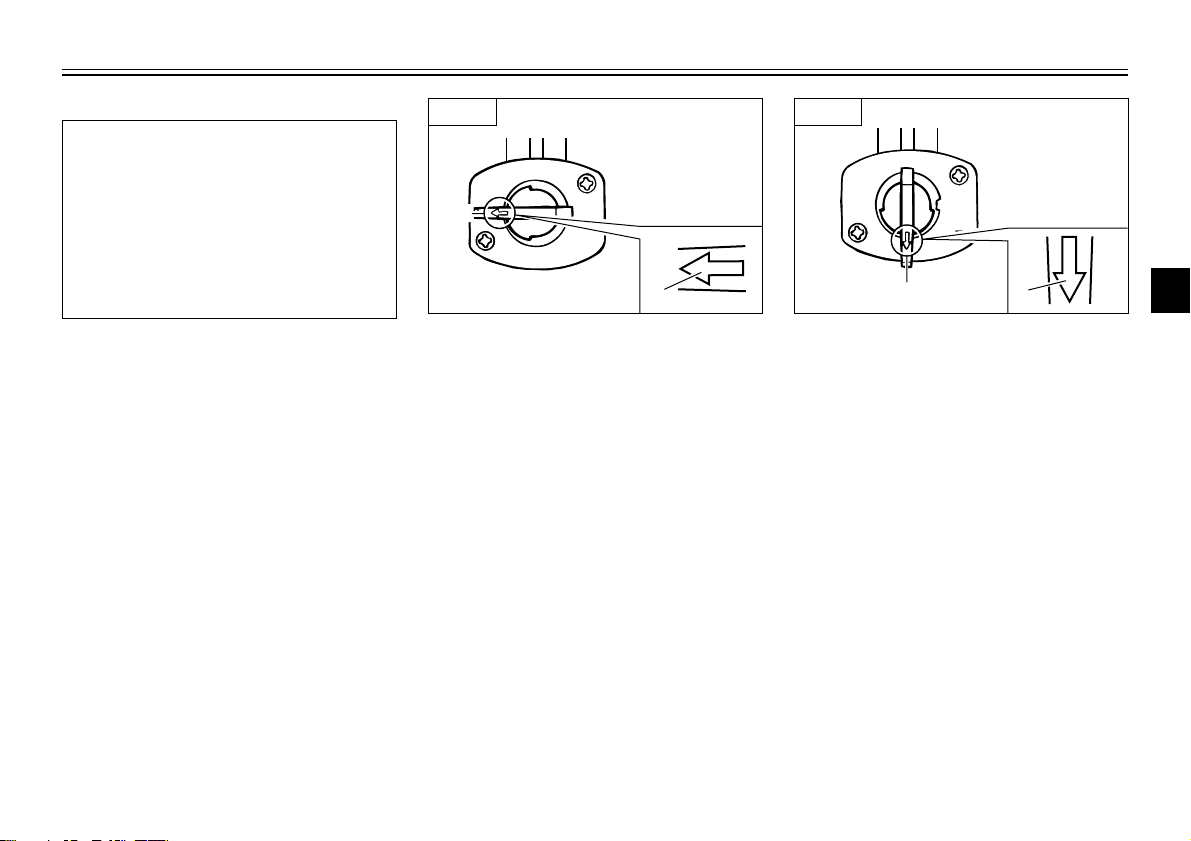
EAU00187
OFF ON
1. Arrow mark
EAU01121
Fuel cock
The fuel cock supplies fuel from
the tank to the carburetor while filtering it also.
The fuel cock has three positions,
which should be set as shown in
the illustrations.
OFF: With the fuel cock in this
position, fuel will not flow.
Always set the fuel cock to
this position when the engine
is not running.
1. Arrow mark
ON: With the fuel cock in this
RES
OFF
FUEL
ON
ON
1
position, fuel flows to the carburetor. Set the fuel cock to
this position when starting
the engine and while riding.
1
2
3
4
5
6
7
8
9
3-7
INSTRUMENT AND CONTROL FUNCTIONS
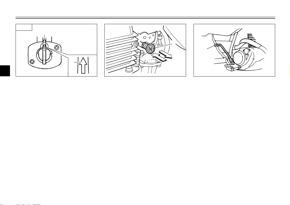
a
b
1
OFF
ON
FUEL
RES
1
RES
1
RES
1
2
3
1. Arrow mark
4
RES: This indicates reserve. If you
5
run out of fuel while riding,
set the fuel cock to this position.
6
Fill the tank at the first opportunity. Be sure to set the fuel
7
cock back to “ON” after refueling!
8
9
1. Starter (choke) “1”
EAU00210
Starter(choke) “1”
Starting a cold engine requires a
richer air-fuel mixture. A separate
starter circuit supplies this mixture.
Move in direction a to turn on the
starter(choke).
Move in direction b to turn off the
starter(choke).
3-8
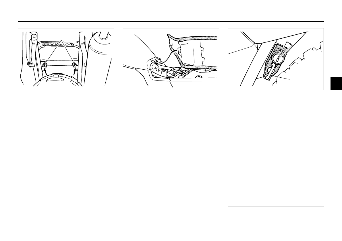
1. Kick starter
EAU00212
Kick starter
Rotate the kick starter away from
the engine. Push the starter down
lightly with your foot until the
gears engage, then kick smoothly
and forcefully to start the engine.
This model has a primary-coupled
kick starter so the engine can be
started in any gear if the clutch is
disengaged. However, shifting to
neutral before starting is recommended.
INSTRUMENT AND CONTROL FUNCTIONS
1
1
1
2
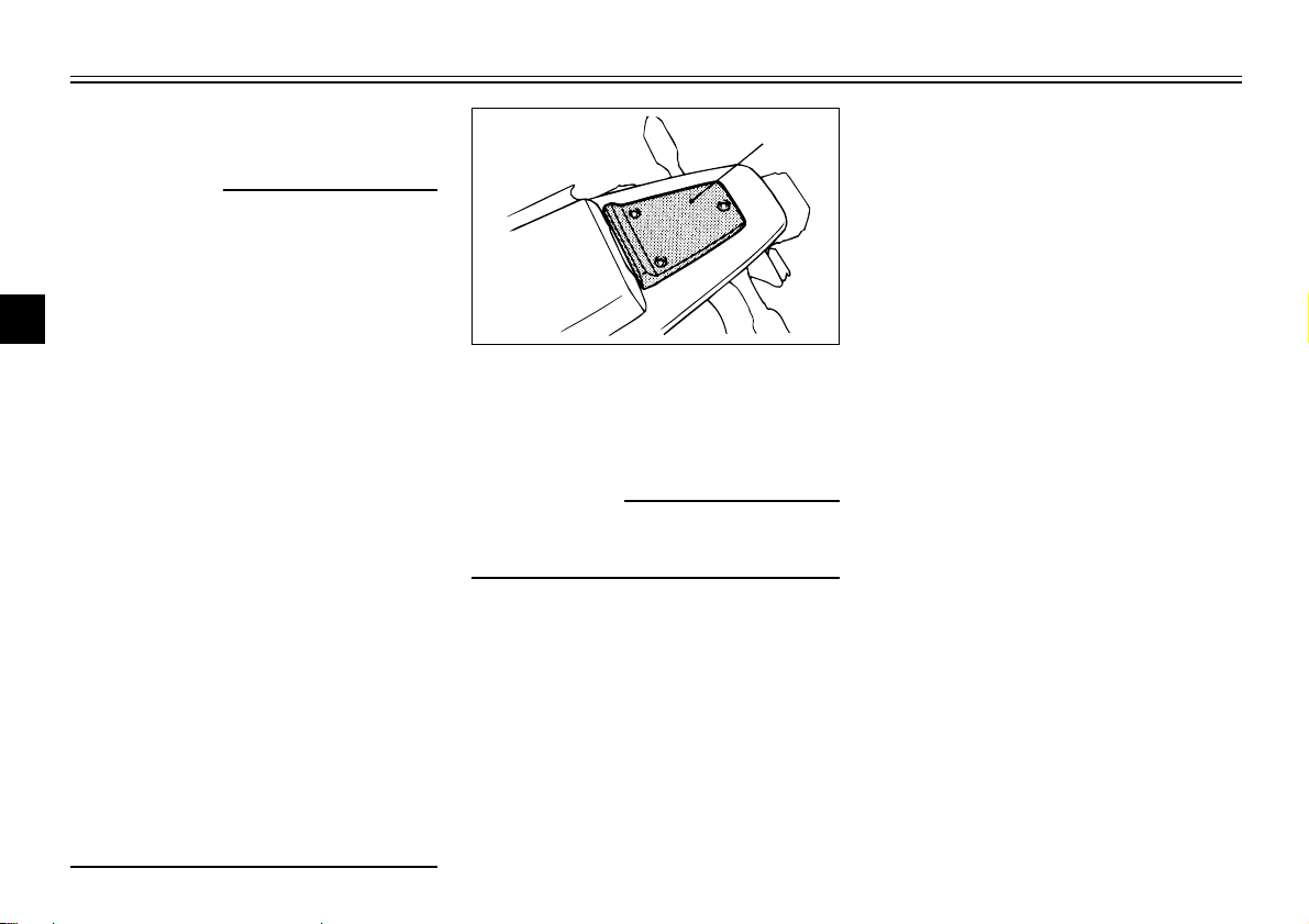
1. Bolt (×2)
EAU01092
Seat
To remove the seat, remove the
bolts.
To install the seat, insert the projection on the front of the seat into
the holder and push down on the
seat, then tighten the bolts.
NOTE:
Make sure that the seat is securely
fitted.
3-9
2
1. Open
2. Helmet holder
EAU00260
Helmet holder
To open the helmet holder, insert
the key in the lock and turn it as
shown. To lock the helmet holder,
replace the holder in its original
position.
EW000030
w
Never ride with a helmet in the
helmet holder. The helmet may hit
objects, causing loss of control
and possibly an accident.
3
4
5
6
7
8
9
1
INSTRUMENT AND CONTROL FUNCTIONS
Rear shock absorber
w
1
This shock absorber contains highly pressurized nitrogen gas. Read
2
and understand the following
information before handling the
3
shock absorber. The manufacturer
cannot be held responsible for
4
property damage or personal
injury that may result from
5
improper handling.
1. Do not tamper with or
6
7
8
9
attempt to open the cylinder
assembly.
2. Do not subject the shock
absorber to an open flame or
other high heat source. This
may cause the unit to explode
due to excessive gas pressure.
3. Do not deform or damage the
cylinder in any way. Cylinder
damage will result in poor
damping performance.
4. Take your shock absorber to a
Yamaha dealer for any service.
EAU01343
EAU00315
EAU00330
Sidestand
This model is equipped with an
ignition circuit cut-off system. The
motorcycle must not be ridden
when the sidestand is down. The
sidestand is located on the left side
of the frame. (Refer to page 5-1 for
an explanation of this system.)
1. Rear carrier
EAU00320
Rear carrier
EW000032
w
Do not exceed the load limit of 3
kg.
3-10
INSTRUMENT AND CONTROL FUNCTIONS
EW000044
w
This motorcycle must not be operated with the sidestand in the
down position. If the stand is not
properly retracted, it could contact
the ground and distract the operator, resulting in a possible loss of
control. Yamaha has designed into
this motorcycle a lockout system
to assist the operator in fulfilling
the responsibility of retracting the
sidestand. Please check carefully
the operating instructions listed
below and if there is any indication
of a malfunction, return the motorcycle to a Yamaha dealer immediately for repair.
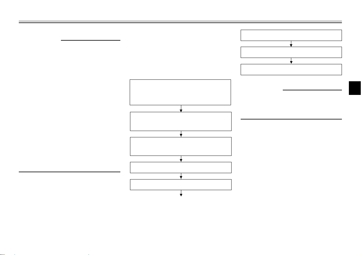
EAU00331
Sidestand/clutch switch
operation check
Check the operation of the sidestand switch and clutch switch
against the information below.
TURN THE MAIN SWITCH TO “ON”
AND THE ENGINE STOP SWITCH TO
“RUN”.
TRANSMISSION IS IN GEAR AND
SIDESTAND IS UP.
PULL IN CLUTCH LEVER AND
PUSH THE START SWITCH.
ENGINE WILL START.
CLUTCH SWITCH IS OK.
SIDESTAND IS DOWN.
ENGINE WILL STALL.
SIDESTAND SWITCH IS OK.
EW000045
w
If improper operation is noted,
consult a Yamaha dealer immediately.
1
2
3
4
5
6
7
8
9
3-11
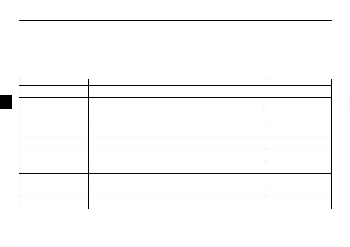
PRE-OPERATION CHECKS
Owners are personally responsible for their vehicle’s condition. Your motorcycle’s vital functions can start to
deteriorate quickly and unexpectedly, even if it remains unused (for instance, if it is exposed to the elements).
Any damage, fluid leak or loss of tire pressure could have serious consequences. Therefore, it is very important
1
that, in addition to a thorough visual inspection, you check the following points before each ride.
EAU01114
2
3
Brakes
4
Clutch
Throttle grip and housing 9 Lubricate. 6-14, 6-24
5
Engine oil
6
Drive chain
7
Wheels and tires
Brake and shift pedal shafts
8
Brake and clutch lever pivots
9
Sidestand pivot
Chassis fasteners
ITEM CHECKS PAGE
9 Check operation, condition and free play.
9 Adjust if necessary.
9 Check operation and free play.
9 Adjust if necessary.
9 Check for smooth operation.
9 Adjust throttle cable free play if necessary.
9 Check oil level.
9 Fill with oil if necessary.
9 Check chain slack and condition.
9 Adjust if necessary.
9 Check tire pressure, wear, damage and spoke tightness.
9 Tighten spokes if necessary.
9 Check for smooth operation.
9 Lubricate if necessary.
9 Check for smooth operation.
9 Lubricate if necessary.
9 Check for smooth operation.
9 Lubricate if necessary.
9 Make sure that all nuts, bolts, and screws are properly tightened.
9 Tighten if necessary.
PRE-OPERATION CHECK LIST
EAU00340
3-5, 6-18 ~ 6-21
3-4, 6-18
6-8 ~ 6-11
6-21 ~ 6-23
6-15 ~ 6-17
6-24
6-25
6-25
—
4-1
 Loading...