

Page 1
Page 2

Page 3

SPECIAL SERVICE TOOL LIST
©2004 Yamaha Motor Co.,Ltd.
1st Edition, August 2004
All rights reserved.
Any reprinting or unauthorized use
without the written permission of
Yamaha Motor Co.,Ltd.
is expressly prohibited.
Printed in Japan
LISTE DES OUTILS D’ENTRETIEN SPÉCIAUX
©2004 Yamaha Motor Co., Ltd.
1ère Edition, Août 2004
Tous droits réservés.
Toute réimpression ou utilisation
sans la permission écrite de la
Ya maha Motor Co., Ltd.
est formellement interdite.
Imprimé en Japon
LISTA DE HERRAMIENTAS ESPECIALES DE
SERVICIO
©2004 Yamaha Motor Co., Ltd.
1ª edición, Agosto 2004
Reservados todos los derechos.
Se prohíbe expresamente toda reimpresión
o utilización no autorizada de este manual
sin el consentimiento por escrito de
Yamaha Motor Co., Ltd.
Impreso en Japón
Page 4

E
NOTICE
This list of special service tools has been prepared for quick and easy reference, to enable you to
find the appropriate service tool(s) for each model.
The special service tools have been improved and upgraded for each new model. However, your
existing service manual does not include the latest information. Also, the list does not cover the
models of which information could not be obtained at the time of preparation of the manual. The
information will be provided through the next issue of the special service tool list.
Outboard motor models : All models to be released only in this fiscal year (except those of
which information can not be obtained )
Watercraft models : All models including those released in several years ago to the lat-
est models (The new models of this fiscal year may be excluded
because the development period of watercrafts is different from that
of the outboard motors.)
The special service tools mentioned in the service manual of each model are listed here.
Tool numbers in round brackets indicate current tool numbers, and will be replaced with the replacement tool numbers (not in brackets) when stock runs out.
In addition, the tool names always appear in English in this manual.
MANUAL FORMAT
APPLICATION CHARTS
Tool numbers and the outboard motor/watercraft models to which they apply are shown in the
charts.
Tools, which are to be supplied in an assembly, are listed with a dot (
) :Dots in round brackets indicate that the particular tool is not absolutely necessary and which
(
•
can be substituted by another tool.
] :Square brackets indicate that the tool applies only to models in square brackets in the corre-
[
sponding column header.
) in front of the tool name.
•
TOOL DESCRIPTIONS
The tool number, name, illustration, and description of its use are shown. The required tool size is
also given to assist in the identification of the correct tool.
The construction and meaning of each section are as follows:
Measuring tool : Mechanical or electrical precision tools (Some measuring tools may
be listed in one of the following sections instead.)
Engine servicing : Special tool for engine servicing
Lower unit/jet pump servicing
Shim selection, PTT tool : Special tool for shim selection and power trim and tilt unit servicing
: Special tool for lower unit/jet pump servicing
REPAIR KITS (RECONDITION TOOL)
The following kits can be used for repairing/replacing damaged parts, avoiding the need to replace
the whole unit. Some skill is required to use these.
“Heli-sert” kit : For reconditioning damaged bolt threads
Marine terminal kit : For repairing conventional marine round plug/socket and eye termi-
nals This water-resistant and rust-resistant connector type, although
similar, is different from that on a motorcycle.
Coupler kit : For repairing water-resistant multiple pole couplers
NOTE:
Identify the correct coupler and do not try to use a coupler of the incorrect type.
INDEX
Find the desired tool through its number (part number) in order to determine the page in the APPLICATION CHARTS and TOOL DESCRIPTIONS, where a more detailed explanation of the tool can
be found.
Page 5

F
NOTE
Cette liste d'outils spéciaux a été préparée afin que les mécaniciens puissent trouver rapidement et aisément le ou les outils spéciaux requis selon les modèles.
Yamaha a modifié et amélioré certains outils d'entretien spéciaux pour les nouveaux modèles. Toutefois, votre manuel
d'atelier existant ne comprend pas ces nouvelles informations. De même, la liste ne concerne pas les modèles dont on ne
disposait pas d'informations au moment de la préparation du manuel. Les informations seront présentées dans la prochaine
publication de la liste d'outils spéciaux.
Modèles de moteur hors-bord : Tous les modèles à sortir cette année fiscale
(à l’exception de ceux à propos desquels on ne peut pas obtenir d’informations)
Modèles de scooters nautiques : Tous les modèles de ceux sortis il y a plusieurs années aux modèles les plus récents
(Les nouveaux modèles de cette année fiscale peuvent être exclus car la période
dedéveloppement des scooters nautiques est différente de celle des moteurs hors-
bord)
Les outils d'entretien spéciaux mentionnés dans le manuel d'atelier pour chaque modèle sont mentionnés ici.
Les numéros d’outils entre parenthèses indiquent les numéros des outils actuels et seront remplacés par les numéros des
outils de rechange (pas entre parenthèses) à l’épuisement du stock.
Le nom des outils figure en anglais.
ORGANISATION DU MANUEL
TABLEAUX D'APPLICATION (APPLICATION CHARTS)
Le numéro des outils spéciaux ainsi que les modèles de moteur hors-bord/de scooter nautique auxquels les outils spéciaux
s'appliquent sont indiqués dans des tableaux.
Dans ce catalogue, les outils qui sont fournis dans un ensemble sont précédés d'un point (•).
(•): Les points entre parenthèses indique que l’outil n’est pas absolument nécessaire et qu’il peut être remplacé par un
autre outil.
[ ]: Les crochets indiquent que l’outil ne s’appliquent qu’aux modèles qui sont entre crochets dans l’en-tête de colonne
correspondante.
FONCTION DES OUTILS (TOOL DESCRIPTIONS)
Les informations données pour chacun de ces outils comprennent leur numéro, leur nom, une représentation graphique
et leur fonction.
Pour plus de commodité d'identification des outils, la taille requise pour l'outil est également indiquée.
Les outils spéciaux sont répartis dans les sections suivantes :
Outil de mesure : Outil de précision mécanique ou électronique (Tous les outils de mesure ne figurent
pas nécessairement dans cette section. Contrôler la liste des sections suiantes.)
Entretien du moteur : Outil spécial requis pour l'entretien du moteur
Entretien du boîtier d'hélice/ : Outil spécial requis pour l'entretien du boîtier d'hélice/pompe de propulsion
pompe de propulsion
Sélection de cales, outil pour PTT : Outil spécial requis pour la sélection de cales et l'entretien du système d'assiette et
d'inclinaison assistées pour PTT
KITS DE REPARATION (OUTIL DE RECONDITIONNEMENT)
Les kits suivants permettent de réparer/remplacer des pièces endommagées et d'ainsi éviter de devoir remplacer les
assemblages.
L'emploi de ces kits de réparation requiert certaines compétences.
Kit de taraudage : Pour le reconditionnement des filetages de boulon endommagés
Kit de bornes marines : Pour la réparation des fiches/prise rondes marines classiques et les cosses. Ce type
de connecteur résistant à l'eau et à la corrosion est différent de celui d'une motocy-
clettes, bien qu'il soit similaire.
Kit de coupleur : Pour la réparation de coupleurs à multipôles étanches
N.B.:
Identifiez le coupleur correct et n'essayez pas d'utiliser un coupleur d'un type incorrect.
INDEX
Les outils sont classés d'après leur numéro. Se servir de ce numéro pour trouver la page des sections Tableaux d'application (APPLICATION CHARTS) et Fonction des outils (TOOL DESCRIPTIONS) contenant les renseignements détaillés de l'outil recherché.
Page 6

ES
AVISO
Esta lista de herramientas de servicio especiales ha sido preparada para encontrar rápida y fácilmente la(s)
herramienta(s) de servicio necesarias para cada modelo respectivo.
Las herramientas de servicio especiales han sido mejoradas para ser utilizadas en los nuevos modelos.
Sin embargo, su manual de servicio existente no cubre la información más reciente. Además, la lista no
incluye los modelos sobre los cuales no pudo obtenerse información en el momento de preparación del manual. Esta información se facilitará en la próxima publicación de la lista de herramientas especiales de servicio.
Modelos de motores fueraborda : Sólo todos los modelos que se lancen en este año fiscal (excepto
aquellos sobre los cuales no puede obtenerse información)
Modelos de embarcaciones : Todos los modelos, incluidos los lanzados, desde hace varios años
hasta los últimos modelos (los modelos nuevos de este año fiscal
pueden ser excluidos porque el período de desarrollo de las embarcaciones es distinto del de los motores fueraborda).
Aquí se enumeran las herramientas especiales de servicio mencionadas en el manual de servicio de cada
modelo.
Los números de herramientas entre paréntesis indican los números de las herramientas nuevas y deben
sustituirse por los números de las herramientas de repuesto (no entre paréntesis) cuando se agoten las existencias.
Además, los nombres de las herramientas siempre aparecen en inglés en este manual.
FORMATO DEL MANUAL
TABLAS DE APLICACIÓN
En las tablas se muestran los números de herramienta y los modelos aplicables de motores fueraborda y
moto de agua.
Las herramientas suministradas como conjunto se señalan con un punto (•) que precede al nombre de la herramienta.
(•): Los puntos entre paréntesis indican que no es absolutamente necesaria la herramienta específica y que
puede sustituirse por otra herramienta.
[ ]: Los corchetes indican que la herramienta se aplica sólo a los modelos entre corchetes en el encabezado
de columna correspondiente.
DESCRIPCION DE LAS HERRAMIENTAS
Se muestran el número, el nombre, y la ilustración de las herramientas, y la descripción de su utilización.
Se indica también el tamaño de la herramienta necesaria para ayudarle a identificarla con más facilidad.
La construcción y el significado de los elementos son los siguientes:
Herramienta de medición : Herramientas de precisión mecánicas o eléctricas (Algunas herramientas
de medición pueden estar enumeradas en una las secciones siguientes.)
Servicio del motor : Herramienta especial para el servicio del motor
Servicio de la unidad inferior/ : Herramienta especial para el servicio de la unidad inferior/bomba de inyecbomba de inyección ción
Selección de laminillas, : Herramienta especial para la selección de laminillas y el servicio de la unherramienta PTT idad de estibado e inclinación motorizados
JUEGOS DE REPARACION (HERRAMIENTA DE REACONDICIONAMIENTO)
Los juegos siguientes pueden utilizarse para la reparación/reemplazo de las partes dañadas para evitar el
reemplazo de toda la unidad. Para emplear estos juegos se necesita experiencia práctica.
Juego “Heli-sert” : Para reacondicionar las roscas de los pernos dañadas
Juego de terminales marinos : Para reparar los terminales de ojal y acopladores redondos convencionales
de uso marino. Este tipo de conector resistente al agua e inoxidable,
aunque similar, es diferente del de una motocicleta.
Juego de acoplador : Para reparar los acopladores multipolares resistentes al agua
NOTA:
Identifique el acoplador correcto y no trate de utilizar un acoplador del tipo incorrecto.
ÍNDICE
Podrá encontrar las herramientas que busca empleando su número (numero de parte) para poder determinar la página de las TABLAS DE APLICACIÓN y de la DESCRIPCIÓN DE LAS HERRAMIENTAS, donde se
da una explicación más detallada de las herramientas.
Page 7

CONTENTS
1.APPLICATION CHART
OUTBOARDS MOTOR TOOL ........................................................................................ 1-1
MEASURING TOOL/PEAK VOLTAGE MEASUREMENT (2 stroke model) .................. 1-1
MEASURING TOOL/PEAK VOLTAGE MEASUREMENT
(Enduro/Kerosene model, 4 stroke model) ................................................................. 1-3
ENGINE SERVICE (2 stroke model) ............................................................................. 1-5
ENGINE SERVICE (Enduro/Kerosine nodel, 4-stroke model) ...................................... 1-7
ENGINE SERVICE (4 stroke model) ............................................................................. 1-9
VALVE SEAT CUTTER (Refering) ........................................................................ 1-10
ENGINE SERVICE (Test propeller) ............................................................................... 1-11
ENGINE SERVICE (Crankshaft disassembly and reassembly) .................................... 1-13
LOWER UNIT SERVICE (2 stroke model) .................................................................... 1-15
LOWER UNIT SERVICE (Enduro/Kerosine nodel, 4-stroke model) ............................. 1-19
SHIM SELECTION/PTT TOOL (2 stroke model) ........................................................... 1-23
SHIM SELECTION/PTT TOOL (Enduro/Kerosine nodel, 4-stroke model) .................... 1-25
WATERCRAFT TOOL ............................................................................................. 1-27
MEASURING TOOL/PEAK VOLTAGE MEASUREMENT ............................................. 1-27
ENGINE SERVICE ........................................................................................................ 1-27
ENGINE SERVICE/JET PUMP SERVICE ..................................................................... 1-29
E
2.TOOL DESCRIPTION
MEASURING TOOL....................................................................................................... 2-1
PEAK VOLTAGE MEASUREMENT ............................................................................... 2-7
ENGINE SERVICE ........................................................................................................ 2-8
4 stroke ................................................................................................................. 2-13
Watercraft.............................................................................................................. 2-16
Crankshaft disassembly and reassembly ............................................................. 2-17
Test propeller ........................................................................................................ 2-18
LOWER UNIT SERVICE/JET PUMP SERVICE ............................................................ 2-19
SHIM SELECTION......................................................................................................... 2-29
PTT TOOL...................................................................................................................... 2-31
3.RECONDITION TOOL
HELI-SERT KIT (90890-05155) ..................................................................................... 3-1
MARINE TERMINAL KIT (90890-05354)....................................................................... 3-2
COUPLER KIT A (61A) (90890-05353) ......................................................................... 3-3
OPTIONAL PARTS ........................................................................................................ 3-4
4.INDEX
INDEX ............................................................................................................................ 4-1
Page 8

TABLE DES MATIERES
1.TABLEAUXD’APPLICATION (APPLICATION CHART)
OUTILS POUR LES MOTEURS HORS-BORD .......................................................................... 1-1
OUTIL DE MESURE/MESURE DE CRÊTES DE TENSION (modèle 2 temps)...................... 1-1
OUTIL DE MESURE/MESURE DE CRÊTES DE TENSION
(modèle enduro/kérosène model, modèle 4 temps) ................................................................... 1-3
D’ENTRETIEN MOTEUR (modèle 2 temps) ............................................................................. 1-5
D’ENTRETIEN MOTEUR (modèle enduro/kérosène model, modèle 4 temps)......................... 1-7
D’ENTRETIEN MOTEUR (modèle 4 temps) ............................................................................. 1-9
FRAISE A SIEGE DE SOUPAPE (référence) .................................................................... 1-10
D’ENTRETIEN MOTEUR (Hélices d’essai) .............................................................................. 1-11
D’ENTRETIEN MOTEUR (Depose et le remontage du vilebreguin) ........................................ 1-13
D’ENTRETIEN BOÎTIER D’HÉLICE (modèle 2 temps) ........................................................... 1-15
D’ENTRETIEN BOÎTIER D’HÉLICE (modèle enduro/kérosène model, modèle 4 temps) ...... 1-19
SÉLECTION DE CALES/OUTIL POUR PTT (modèle 2 temps) ............................................... 1-23
SÉLECTION DE CALES/OUTIL POUR PTT
(modèle enduro/kérosène model, modèle 4 temps) ................................................................... 1-25
F
OUTILS POUR LES SCOOTER NAUTIQUES .................................................................... 1-27
OUTIL DE MESURE/MESURE DE CRÊTES DE TENSION ................................................... 1-27
D’ENTRETIEN MOTEUR .......................................................................................................... 1-27
D’ENTRETIEN MOTEUR/D’ENTRETIEN POMPE DE PROPULSION ................................ 1-29
2.FONCTION DES OUTILS (TOOL DESCRIPTION)
OUTIL DE MESURE ................................................................................................................... 2-1
MESURE DE CRÊTES DE TENSION........................................................................................ 2-7
D’ENTRETIEN MOTEUR .......................................................................................................... 2-8
4 temps ................................................................................................................................ 2-13
Scooter Nautiques ............................................................................................................... 2-16
Depose et le remontage du vilebreguin............................................................................... 2-17
Hélices d’essai..................................................................................................................... 2-18
D’ENTRETIEN BOÎTIER D’HÉLICE/D’ENTRETIEN POMPE DE PROPULSION .............. 2-19
SÉLECTION DE CALES ............................................................................................................. 2-29
OUTIL POUR PTT ....................................................................................................................... 2-31
3.OUTIL DE REVISION (RECONDITION TOOL)
KIT DE TARAUDAGE (90890-05155) ....................................................................................... 3-1
KIT DE BORNES (90890-05354) ................................................................................................ 3-2
KIT DE COUPLEURS A (61A) (90890-05353) .......................................................................... 3-3
PIÈCES EN OPTION ................................................................................................................... 3-4
4.INDEX (INDEX)
INDEX .......................................................................................................................................... 4-1
Page 9

CONTENIDO
1.GRÁFICAS DE APLICACIÓN (APPLICATION CHART)
HERRAMIENTAS PARA MOTORES DE FUERA DE BORDA.................................. 1-1
HERRAMIENTA DE MEDICIÓN/MEDICIÓN DE LA TENSIÓN PICO
(modelo de 2 tiempos) ................................................................................................ 1-1
HERRAMIENTA DE MEDICIÓN/MEDICIÓN DE LA TENSIÓN PICO
(modelo Enduro/Keroseno, modelo de 4 tiempos) ..................................................... 1-3
SERVICIO DEL MOTOR (modelo de 2 tiempos) .......................................................... 1-5
SERVICIO DEL MOTOR (modelo Enduro/Keroseno, modelo de 4 tiempos) ............... 1-7
SERVICIO DEL MOTOR (modelo de 4 tiempos) .......................................................... 1-9
CORTADOR DE ASIENTO DE VÁLVULA (referencia) ......................................... 1-10
SERVICIO DEL MOTOR (Hélices de prueba) . ............................................................. 1-11
SERVICIO DEL MOTOR (Desmontage yel montage delcigüeñal)................................ 1-13
SERVICIO DE UNIDAD IN FERIOR/BOMBA DEINYECCIÓN
SERVICIO DE UNIDAD IN FERIOR/BOMBA DEINYECCIÓN
(modelo Enduro/Keroseno, modelo de 4 tiempos) ..................................................... 1-19
SELECCIÓN DE LAMINILLAS/HERRAMIENTA PTT (modelo 2 tiempos).................... 1-23
SELECCIÓN DE LAMINILLAS/HERRAMIENTA PTT
(modelo Enduro/Keroseno, modelo de 4 tiempos) ..................................................... 1-25
(modelo de 2 tiempos)
ES
... 1-15
HERRAMIENTAS PARA MOTO DE AGUA .................................................................. 1-27
HERRAMIENTA DE MEDICIÓN/MEDICIÓN DE LA TENSIÓN PICO ........................... 1-27
SERVICIO DEL MOTOR................................................................................................ 1-27
SERVICIO DEL MOTOR/ESERVICIO DE BOMBA DE INYECCIÓN............................ 1-29
2.DESCRIPCION DE LAS HERRAMIENTA (TOOL DESCRIPTION)
HERRAMIENTA DE MEDICIÓN .................................................................................... 2-1
MEDICIÓN DE LA TENSIÓN PICO............................................................................... 2-7
SERVICIO DEL MOTOR................................................................................................ 2-8
4 tiempos............................................................................................................... 2-13
Moto de agua ........................................................................................................ 2-16
Desmontage yel montage del cigüeñal................................................................. 2-17
Hélices de prueba ................................................................................................. 2-18
SERVICIO DE UNIDAD IN FERIOR/BOMBA DE INYECCIÓN ..................................... 2-19
SELECCIÓN DE LAMINILLAS ...................................................................................... 2-29
HERRAMIENTA PTT ..................................................................................................... 2-31
3.HERRAMIENTAS REACONDICION (RECONDITION TOOL)
JUEGO HELI-SERT (90890-05155) .............................................................................. 3-1
JUEGO DE TERMINALES MARINOS (90890-05354).................................................. 3-2
JUEGO DE ACOPLADOR A (61A) (90890-05353)
PA RTE DE OPTIONAL .................................................................................................. 3-4
................................................... 3-3
4.ÍNDICE (INDEX)
ÍNDICE ........................................................................................................................... 4-1
Page 10
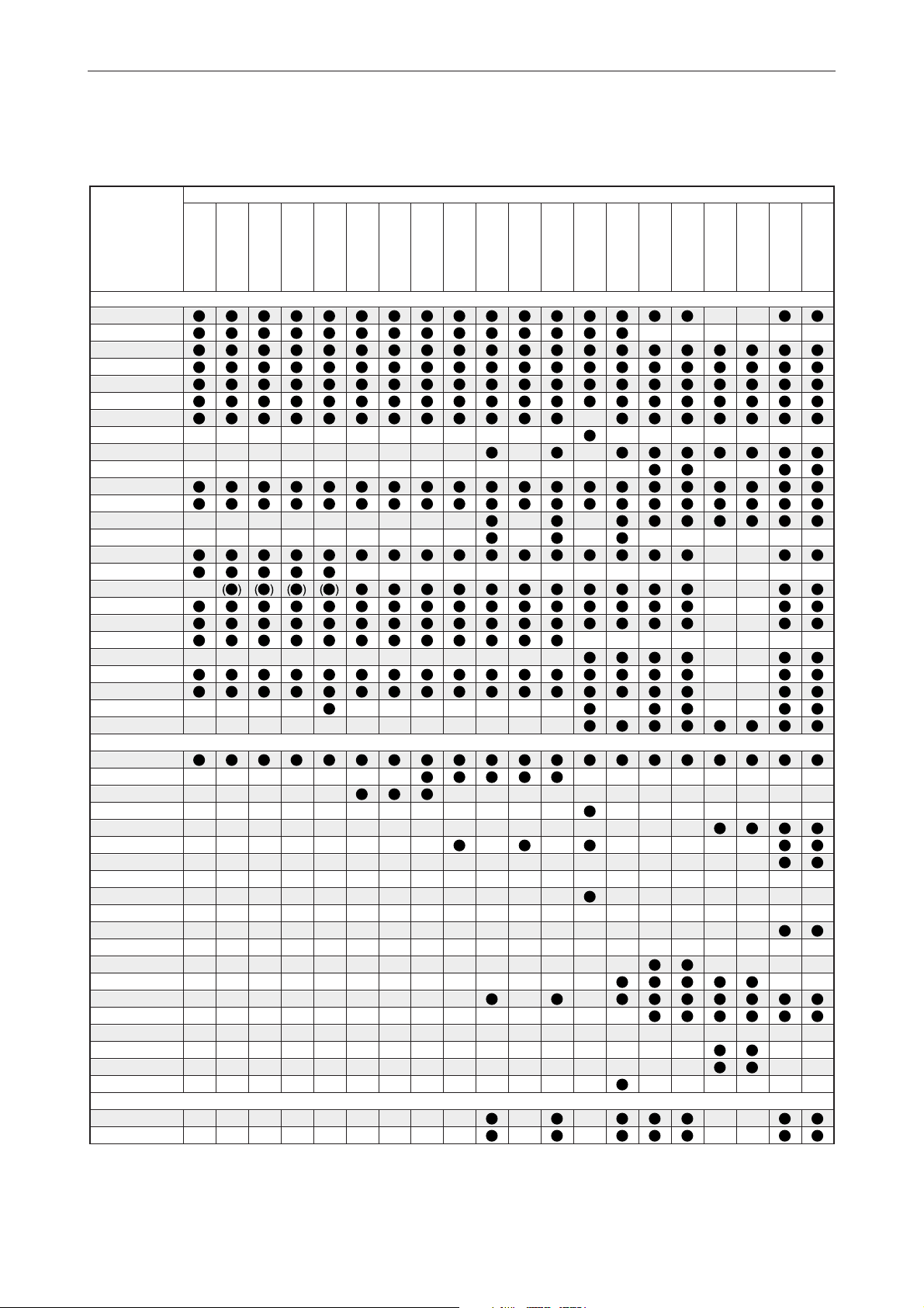
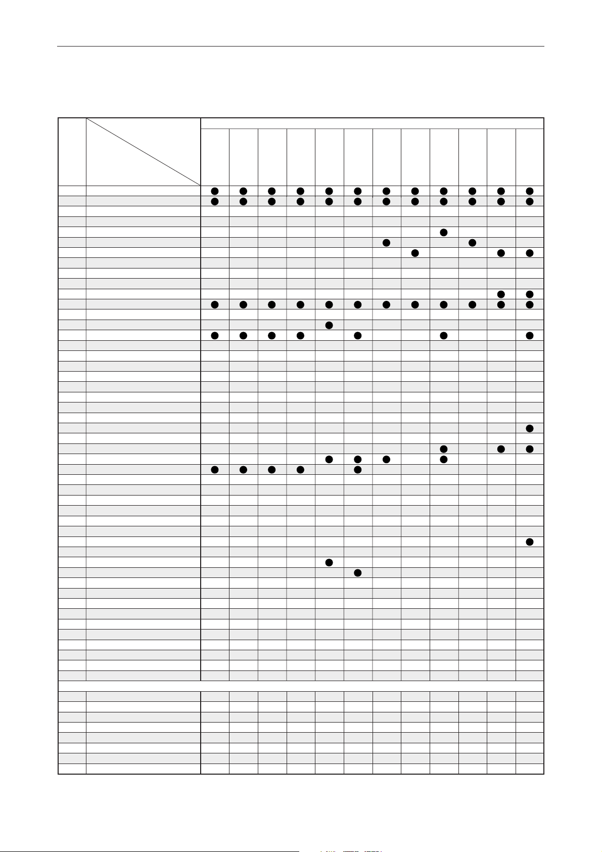
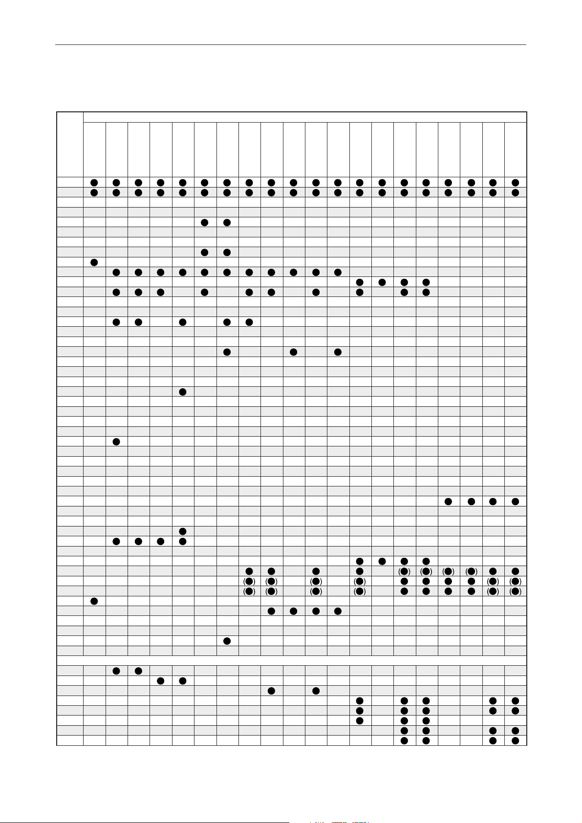
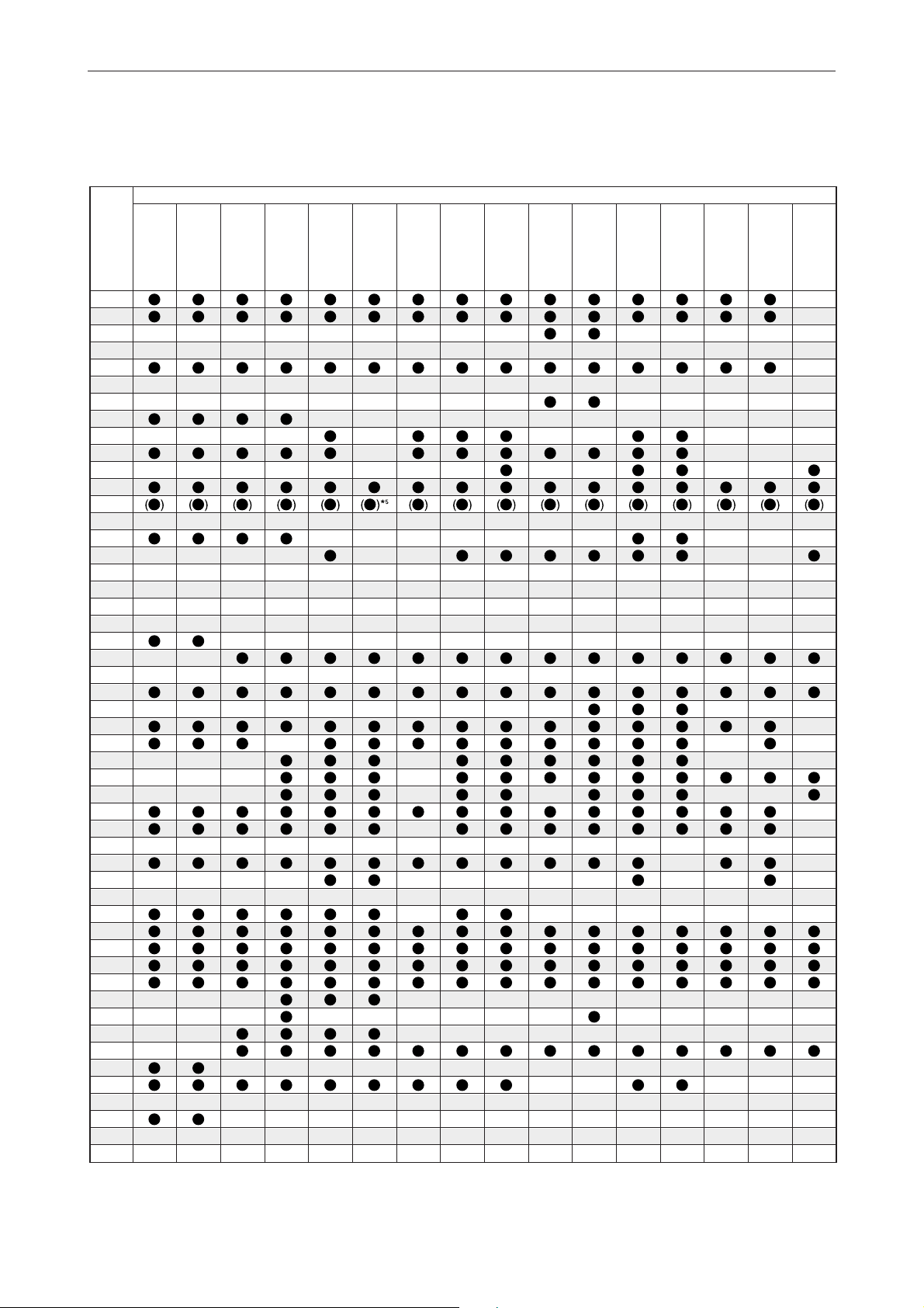
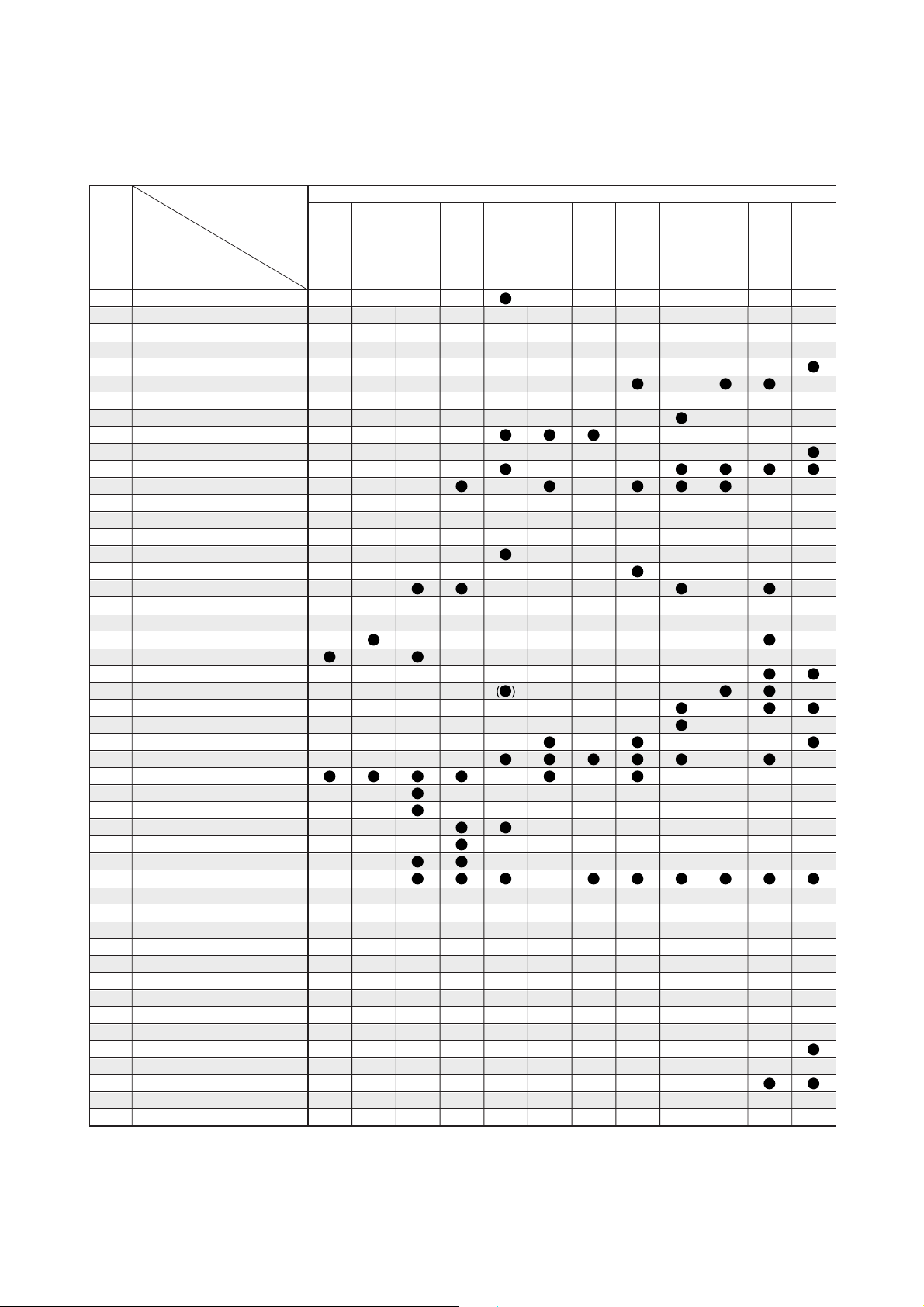
OUTBOARDS MOTOR TOOL
MEASURING TOOL/PEAK VOLTAGE MEASUREMENT
(2 stroke model)
APPLICATION CHART
Tool
No.
90890-
MEASURING TOOL
01252
03112
03141
03160
03174
06754
06756
06757
06865
06864
06760
06840
06786
06942
06704
03016
06759
03006
03007
03008
03009
03010
03180
03107
06563
PEAK VOLTAGE MEASUREMENT
03172
06867 (06767)
06868 (06768)
06857 (06757)
06869 (06769)
06870 (06770)
06871 (06771)
06875 (06775)
06872 (06772)
06879 (06779)
06887 (06787)
06888 (06788)
06790
06791
06792
06793
06861
06846
06847
06848
YAMAHA DIAGNOSTIC SYSTEM
60V-85300-02
60V-WS853-02
Dial gauge set
Pocket tester
Timing light
Compression gauge
Digital circuit tester
Ignition tester
Vacuum/pressure pump gauge set
Throttle sensor adjusting lead FWY-3
Diagnostic flash indicator B
Diagnostic flash adapter 4
Digital tachometer
Leakage tester
Fuel pressure gauge
Fuel pressure gauge adapter B
Digital caliper
Cylinder gauge 35 - 60
Cylinder gauge 50 - 100
Outside micrometer 0 - 25
Outside micrometer 25 - 50
Outside micrometer 50 - 75
Outside micrometer 75 - 100
Inside micrometer 5 - 25
Thickness gauge
Crankshaft aligner
Compression gauge extension M14
Peak voltage adapter B
Test harness FWY-2
Test harness EJ-II-2
Throttle sensor adjusting lead FWY-3
Test harness EJ-II-3
Test harness SMT250-3
Test harness FWY-4
Test harness AMP-4
Test harness FWY-6
Test harness FWY-8
Test harness FW13613-2
Test harness FW13613-1
Test harness FSW-6
Test harness FWY-3-L
Test harness SMHW090-2
Test harness SMHW099-3
Test harness SM6195043
Test harness QLW-3
Test harness QLWD-3
Test harness FSW-6A
Yamaha Diagnostic System (KIT)
Yamaha Diagnostic System(CD-ROM) *5
MODEL
2B
2C
3A
4AC
4AS
5C
5CS
6C
8C
9.9F
13.5A
15F
2 Stroke model
20D
20C
25N
25B
25X
30H
30D
40V
40Y
50H
55B
50G
60F
70B
*1 V4 :115B, 115C, 130B, 140B, 140C
2
V6 :150F, 150G, 150J, 150L, 175D, 200F, 200G,
*
200H, 200J, 225D, 225G
3
*
Electronic fuel injectioned model only
4
2 stroke model
*
5
Up-date CD-ROM only
*
1-1
Page 11
01252
03112
03141
03160
03174
06754
06756
06757
06865
06864
06760
06840
06786
06942
06704
03016
06759
03006
03007
03008
03009
03010
03180
03107
06563
Tool
No.
90890-
55D
75A
75B
85A
75C
80A
90A
V4*
1
L130B
V6*2D150N
150A
175A
200A
2 Stroke model
L150F
L150J
L150A
L200F
L200A
L200J
225C
250A
225F
250B
APPLICATION CHART
Z150P
L225C
L250A
L225F
L250B
Z150Q
Z175G
Z175H
Z200N
Z200P
LZ150P
LZ200N
Z225H
Z250F
Z250D
Z300A
Z300B
LZ250D
LZ300A
03172
06867 (06767)
06868 (06768)
06857 (06757)
06869 (06769)
06870 (06770)
06871 (06771)
06875 (06775)
06872 (06772)
06879 (06779)
06887 (06787)
06888 (06788)
06790
06791
06792
06793
06861
06846
06847
06848
60V-85300-02
60V-WS853-02
1-2
Page 12
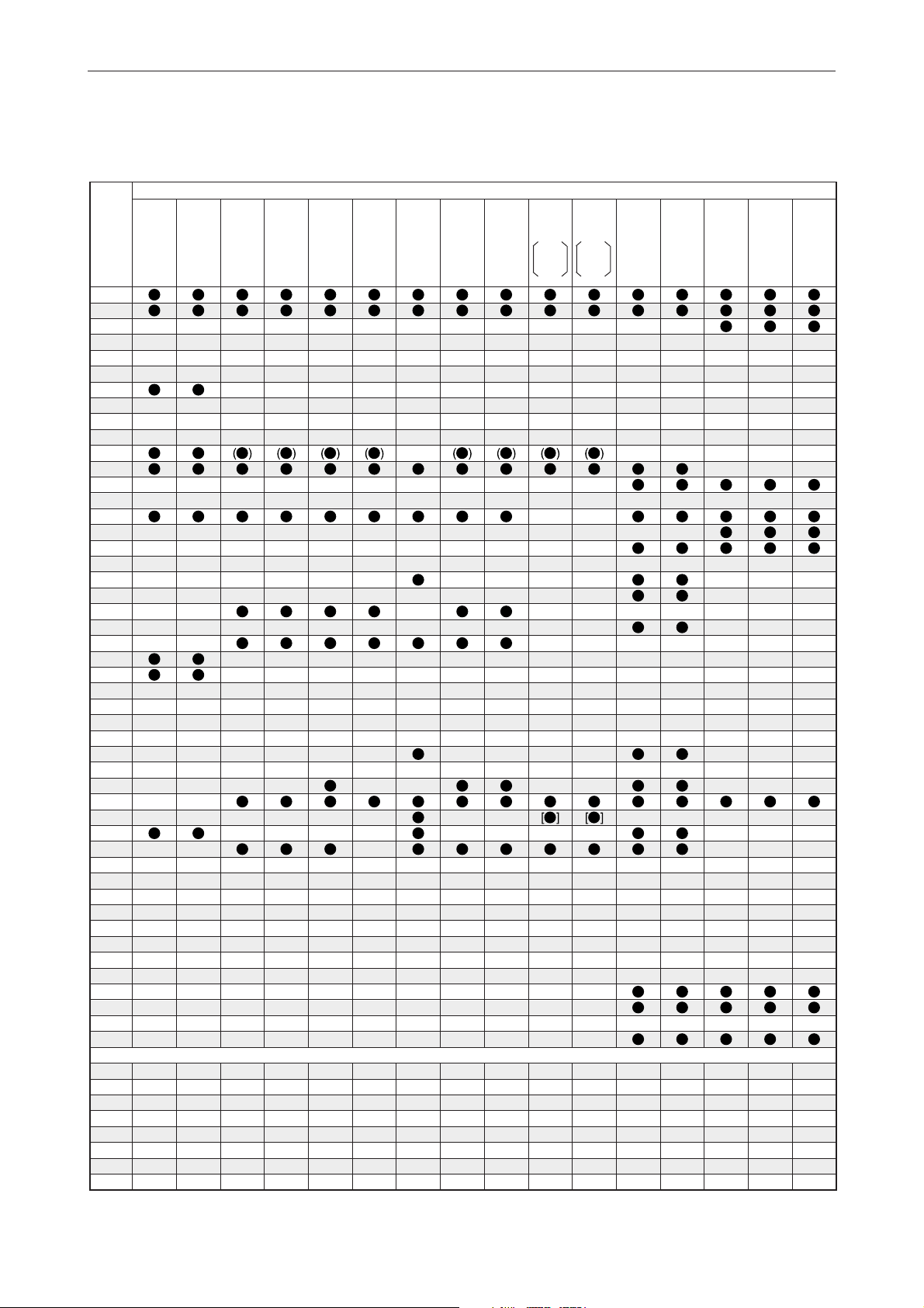
MEASURING TOOL/PEAK VOLTAGE MEASUREMENT
(Enduro/Kerosene model, 4 stroke model)
APPLICATION CHART
Tool
No.
90890-
MEASURING TOOL
01252
03112
03141
03160
03174
06754
06756
06757
06865
06864
06760
06840
06786
06942
06704
03016
06759
03006
03007
03008
03009
03010
03180
03107
06563
PEAK VOLTAGE MEASUREMENT
03172
06867 (06767)
06868 (06768)
06857 (06757)
06869 (06769)
06870 (06770)
06871 (06771)
06875 (06775)
06872 (06772)
06879 (06779)
06887 (06787)
06888 (06788)
06790
06791
06792
06793
06861
06846
06847
06848
YAMAHA DIAGNOSTIC SYSTEM
60V-85300-02
60V-WS853-02
Dial gauge set
Pocket tester
Timing light
Compression gauge
Digital circuit tester
Ignition tester
Vacuum/pressure pump gauge set
Throttle sensor adjusting lead FWY-3
Diagnostic flash indicator B
Diagnostic flash adapter 4
Digital tachometer
Leakage tester
Fuel pressure gauge
Fuel pressure gauge adapter B
Digital caliper
Cylinder gauge 35 - 60
Cylinder gauge 50 - 100
Outside micrometer 0 - 25
Outside micrometer 25 - 50
Outside micrometer 50 - 75
Outside micrometer 75 - 100
Inside micrometer 5 - 25
Thickness gauge
Crankshaft aligner
Compression gauge extension M14
Peak voltage adapter B
Test harness FWY-2
Test harness EJ-II-2
Throttle sensor adjusting lead FWY-3
Test harness EJ-II-3
Test harness SMT250-3
Test harness FWY-4
Test harness AMP-4
Test harness FWY-6
Test harness FWY-8
Test harness FW13613-2
Test harness FW13613-1
Test harness FSW-6
Test harness FWY-3-L
Test harness SMHW090-2
Test harness SMHW099-3
Test harness SM6195043
Test harness QLW-3
Test harness QLWD-3
Test harness FSW-6A
Yamaha Diagnostic System (KIT)
Yamaha Diagnostic System(CD-ROM) *5
MODEL
E8D
EK8D
E9.9D
E15D
EK9.9D
EK15D
EK9.9J
EK15P
EK9.9H
EK15N
Enduro/Kerosene model 4 Stroke model
E25B
EK25B
E30H
4
40G*
E40G
EK40G
E40X
40X*
40J*
4
K40J
4
E48C
E55C
E60H
K50E
E60J
E65A
E75B
E115A
F2.5A
F4A
F6A
F6B
F8C
*1 V4 :115B, 115C, 130B, 140B, 140C
2
V6 :150F, 150G, 150J, 150L, 175D, 200F, 200G,
*
200H, 200J, 225D, 225G
3
*
Electronic fuel injectioned model only
4
2 stroke model
*
5
Up-date CD-ROM only
*
1-3
Page 13
01252
03112
03141
03160
03174
06754
06756
06757
06865
06864
06760
06840
06786
06942
06704
03016
06759
03006
03007
03008
03009
03010
03180
03107
06563
Tool
No.
90890-
FT8D
F9.9B
FT9.9A
F9.9C
FT9.9D
F15B F25C
F13.5A
F15A
F20A
F25A
FT25B
F30A
F40B
4 Stroke model
F50A
F50F
F50D
F60C
F60A
FT50B
FT50C
FT60B
FT50G
FT60D
APPLICATION CHART
F75A
F80A
F75B
F90A
F100A
F100B
F100C
F90B
F115A
FL115A
F150A
FL150A
F200A
F225A
FL200A
FL225A
03172
06867 (06767)
06868 (06768)
06857 (06757)
06869 (06769)
06870 (06770)
06871 (06771)
06875 (06775)
06872 (06772)
06879 (06779)
06887 (06787)
06888 (06788)
06790
06791
06792
06793
06861
06846
06847
06848
60V-85300-02
60V-WS853-02
1-4
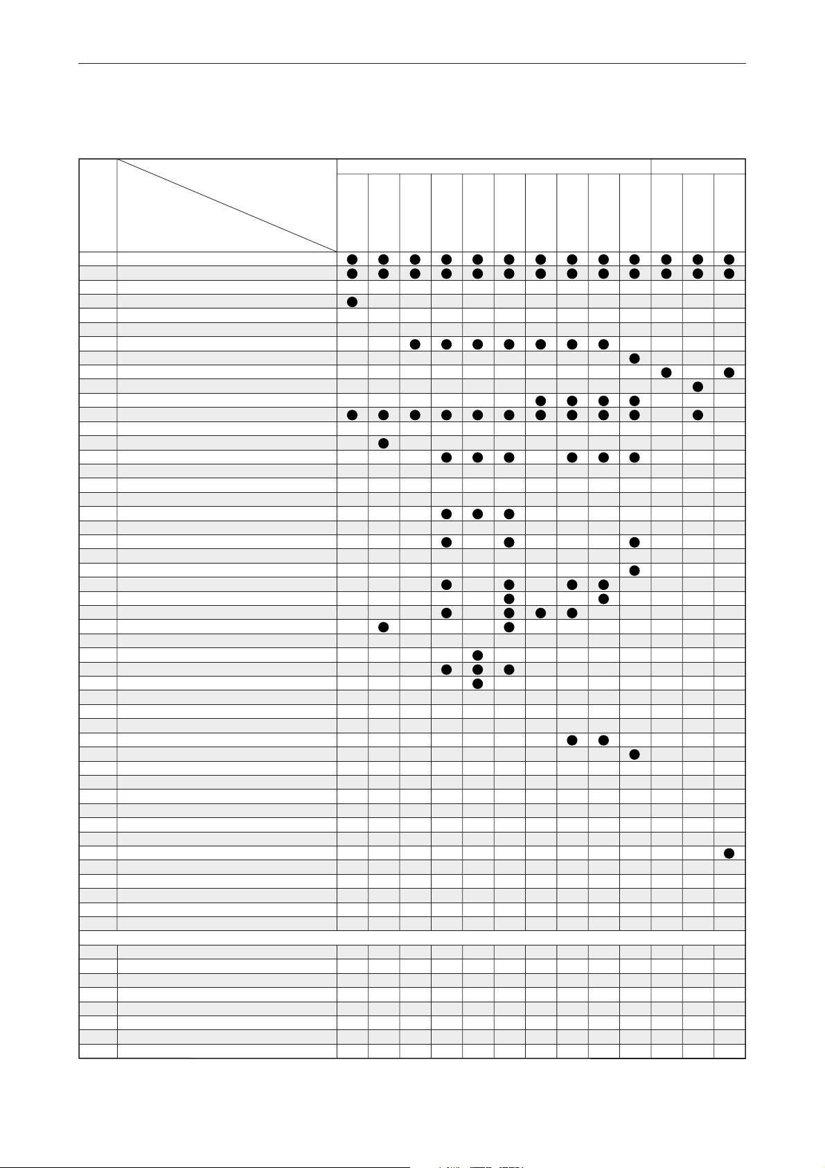
Page 14
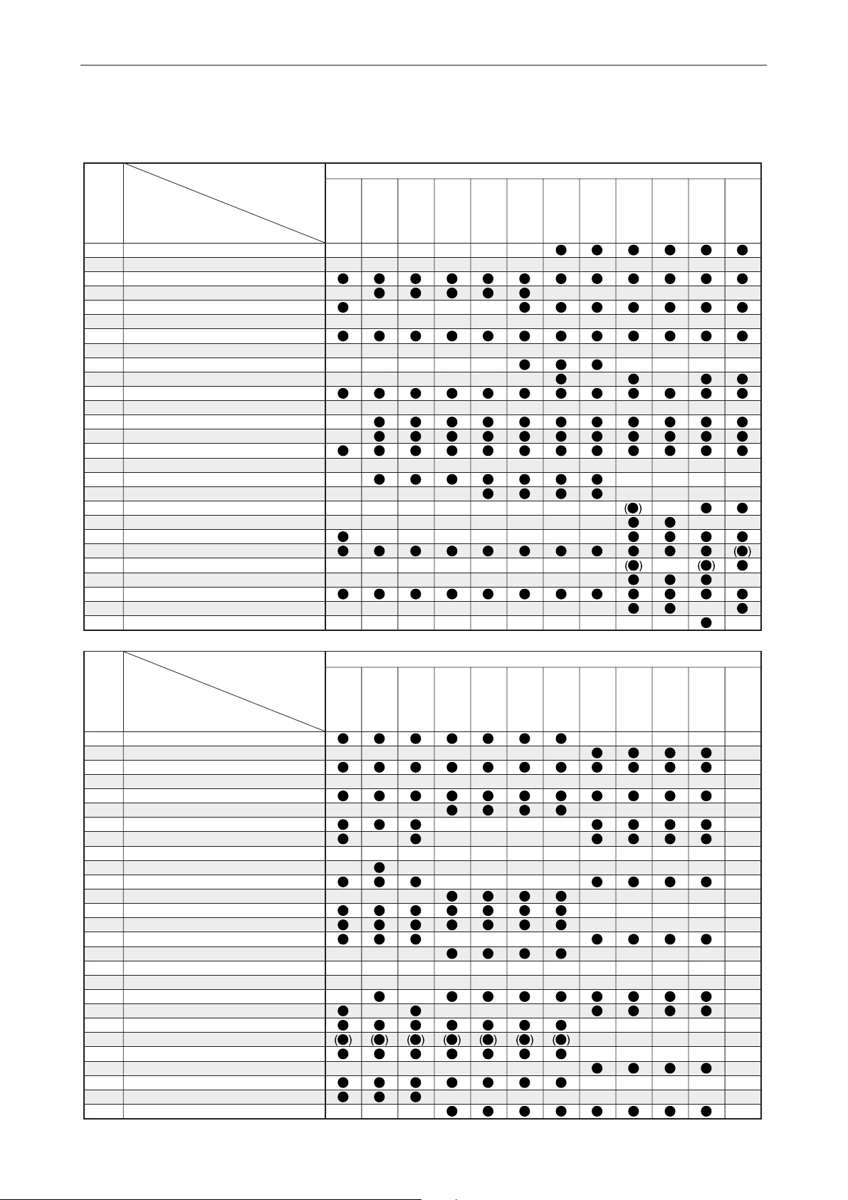
ENGINE SERVICE
(2 stroke model)
APPLICATION CHART
Tool
No.
90890-
06521
06522
06523
06524
06525
06526
06527
06528
06843
06529
06530
06534
06540
06543
06606
06623
06624
06626
06652
06630
06631
06635
06637
06639
06640
06641
06644
06645
06613
06654
06655
06660
05158
06661
06662
06663
06069
06355
06552
03159
03094
03060
06561
06562
01235
01701
04086
06991
GENERAL TOOL
Flywheel puller
Flywheel holder
Bearing outer race puller Assy
Small end bearing installer
Small end bearing installer
Small end bearing installer
Small end bearing installer
Small end bearing installer
Piston slider ø58
Piston slider ø70
Piston slider ø85
Bearing separator
Gear puller
Small end bearing installer
Driver rod LS
Bearing outer race attachment
Bearing outer race attachment
Bearing outer race attachment
Driver rod L3
Ball bearing attachment
Ball bearing attachment
Ball bearing attachment
Ball bearing attachment
Bearing inner race attachment
Bearing inner race attachment
Bearing inner race attachment
Bearing inner race attachment
Bearing inner race attachment
Needle bearing attachment
Needle bearing attachment
Ball bearing attachment
Bearing inner race attachment
Piston ring compressor
Bearing inner race attachment
Bearing inner race attachment
Ball bearing attachment
Shaft holder
Crankshaft holder 16
Crankshaft holder 20
Vacuum gauge
Vacuum gauge [Selector type]
• Attachment
Crankshaft holder 12
Crankshaft holder 18
Rotor holder
Sheave holder
Universal clutch holder
Injector grease
G1
Deep socket 1 (30
Deep socket 2 (36
G2
Deep socket 3 (41
G3
Deep socket 4 (46
G4
T-type TORX socket T55
G5
E-type TORX socket E10
G6
TORX tamper resistant driver T20
G7
TORX tamper resistant driver T25
G8
MODEL
X
100)
X
100)
X
100)
X
100)
2B
2C
3A
4AC
4AS
5C
5CS
6C
8C
9.9F
13.5A
15F
2 Stroke model
20D
20C
25N
25B
25X
30H
30D
40V
40Y
50H
55B
50G
60F
70B
*1 V4 :115B, 115C, 130B, 140B, 140C
2
V6 :150F, 150G, 150J, 150L, 175D, 200F, 200G,
*
200H, 200J, 225D, 225G
3
*
Electronic fuel injectioned model only
4
2 stroke model
*
1-5
Page 15
Tool
No.
90890-
06521
06522
06523
06524
06525
06526
06527
06528
06843
06529
06530
06534
06540
06543
06606
06623
06624
06626
06652
06630
06631
06635
06637
06639
06640
06641
06644
06645
06613
06654
06655
06660
05158
06661
06662
06663
06069
06355
06552
03159
03094
03060
06561
06562
01235
01701
04086
06991
55D
75A
75B
85A
75C
80A
90A
1
L130B V6*2D150N
V4*
150A
175A
200A
2 Stroke model
L150J
L150A
L200F
L200A
L200J
225C
250A
225F
250B
APPLICATION CHART
Z150P
L225C
L250A
L225F
L250B
Z150Q
Z175G
Z175H
Z200N
Z200P
LZ150P
LZ200N
Z225H
Z250F
Z250D
Z300A
Z300B
LZ250D
LZ300A
G1
G2
G3
G4
G5
G6
G7
G8
1-6
Page 16
ENGINE SERVICE
(Enduro/Kerosene model, 4 stroke model)
APPLICATION CHART
Tool
No.
90890-
Flywheel puller
06521
Flywheel holder
06522
Bearing outer race puller Assy
06523
Small end bearing installer
06524
Small end bearing installer
06525
Small end bearing installer
06526
Small end bearing installer
06527
Small end bearing installer
06528
Piston slider ø58
06843
Piston slider ø70
06529
Piston slider ø85
06530
Bearing separator
06534
Gear puller
06540
Small end bearing installer
06543
Driver rod LS
06606
Bearing outer race attachment
06623
Bearing outer race attachment
06624
Bearing outer race attachment
06626
Driver rod L3
06652
Ball bearing attachment
06630
Ball bearing attachment
06631
Ball bearing attachment
06635
Ball bearing attachment
06637
Bearing inner race attachment
06639
Bearing inner race attachment
06640
Bearing inner race attachment
06641
Bearing inner race attachment
06644
Bearing inner race attachment
06645
Needle bearing attachment
06613
Needle bearing attachment
06654
Ball bearing attachment
06655
Bearing inner race attachment
06660
Piston ring compressor
05158
Bearing inner race attachment
06661
Bearing inner race attachment
06662
Ball bearing attachment
06663
Shaft holder
06069
Crankshaft holder 16
06355
Crankshaft holder 20
06552
Vacuum gauge
03159
Vacuum gauge [Selector type]
03094
• Attachment
03060
Crankshaft holder 12
06561
Crankshaft holder 18
06562
Rotor holder
01235
Sheave holder
01701
Universal clutch holder
04086
Injector grease
06991
GENERAL TOOL
G1
Deep socket 1 (30
G2
Deep socket 2 (36 X 100)
G3
Deep socket 3 (41 X 100)
G4
Deep socket 4 (46 X 100)
G5
T-type TORX socket T55
G6
E-type TORX socket E10
G7
TORX tamper resistant driver T20
G8
TORX tamper resistant driver T25
X
100)
MODEL
E8D
EK8D
E9.9D
E15D
EK9.9D
EK15D
EK9.9J
EK15P
EK9.9H
EK15N
Enduro/Kerosene model
E25B
EK25B
E30H
4
40G*
E40G
EK40G
E40X
40X*
4
40J*
K40J
4
E48C
E55C
E60H
K50E
E60J
E65A
E75B
E115A
4 Stroke model
F2.5A
F4A
F6A
F6B
F8C
*1 V4 :115B, 115C, 130B, 140B, 140C
2
V6 :150F, 150G, 150J, 150L, 175D, 200F, 200G,
*
200H, 200J, 225D, 225G
3
*
Electronic fuel injectioned model only
4
2 stroke model
*
1-7
Page 17
Tool
No.
90890-
06521
06522
06523
06524
06525
06526
06527
06528
06843
06529
06530
06534
06540
06543
06606
06623
06624
06626
06652
06630
06631
06635
06637
06639
06640
06641
06644
06645
06613
06654
06655
06660
05158
06661
06662
06663
06069
06355
06552
03159
03094
03060
06561
06562
01235
01701
04086
06991
FT8D
F9.9B
FT9.9A
F9.9C
FT9.9D
F15B F25C
F13.5A
F15A
F20A
F25A
FT25B
F30A
F40B
F50A
F50D
F60A
4 Stroke model
FT50B
F50F
FT50C
F60C
FT60B
FT50G
FT60D
F75A
F80A
F90A
F100A
F100B
F100C
APPLICATION CHART
F75B
F90B
F115A
FL115A
F150A
FL150A
F200A
F225A
FL200A
FL225A
G1
G2
G3
G4
G5
G6
G7
G8
1-8
Page 18
ENGINE SERVICE
(4 stroke model)
APPLICATION CHART
Tool
No.
90890-
01426
06830
04019
04108
06320
04064
06801
06810
06802
04015
06804
04066
05041
04101
06316
06553
06313
06314
06326
06327
06328
06312
06555
06325
06315
06323
06324
MODEL
Oil filter wrench 64
Oil filter wrench 72.5
Valve spring compressor
Valve spring compressor attachment
Valve spring compressor attachment
Valve guide remover/installer 5.9
Valve guide remover/installer 5.4
Valve guide installer 5.5
Valve guide installer 5.4
Valve guide installer 5.6
Valve guide reamer 5.5
Valve guide reamer 6.02
Tap handle (5–6)
Valve lapper
Valve seat cutter holder ø5.5
Valve seat cutter holder ø6.0
Valve seat cutter 5°-25
Valve seat cutter 5°-29
Valve seat cutter 30°-32.5
Valve seat cutter 30°-35
Valve seat cutter 30°-27
Valve seat cutter 45°-27.5
Valve seat cutter 45°-30
Valve seat cutter 45°-35
Valve seat cutter 60°-26
Valve seat cutter 60°-31
Valve seat cutter 60°-36
F2.5A
F4A
F6A
F6B
F8C
4 Stroke model
F9.9C
FT8D
F9.9B F15B F25C
FT9.9A
FT9.9D
F13.5A
F15A
F20A
F25A
FT25B
F30A
F40B
F50A
F50D
F60A
Tool
No.
90890-
01426
06830
04019
04108
06320
04064
06801
06810
06802
04015
06804
04066
05041
04101
06316
06553
06313
06314
06326
06327
06328
06312
06555
06325
06315
06323
06324
MODEL
Oil filter wrench 64
Oil filter wrench 72.5
Valve spring compressor
Valve spring compressor attachment
Valve spring compressor attachment
Valve guide remover/installer 5.9
Valve guide remover/installer 5.4
Valve guide installer 5.5
Valve guide installer 5.4
Valve guide installer 5.6
Valve guide reamer 5.5
Valve guide reamer 6.02
Tap handle (5–6)
Valve lapper
Valve seat cutter holder ø5.5
Valve seat cutter holder ø6.0
Valve seat cutter 5°-25
Valve seat cutter 5°-29
Valve seat cutter 30°-32.5
Valve seat cutter 30°-35
Valve seat cutter 30°-27
Valve seat cutter 45°-27.5
Valve seat cutter 45°-30
Valve seat cutter 45°-35
Valve seat cutter 60°-26
Valve seat cutter 60°-31
Valve seat cutter 60°-36
F50F
F60C
FT50B
FT50C
FT60B
FT50G
FT60D
F75A
F80A
F90A
F100A
F100B
F100C
F75B
F90B
4 Stroke model
F115A
FL115A
F150A
FL150A
F200A
F225A
FL200A
FL225A
1-9
Page 19
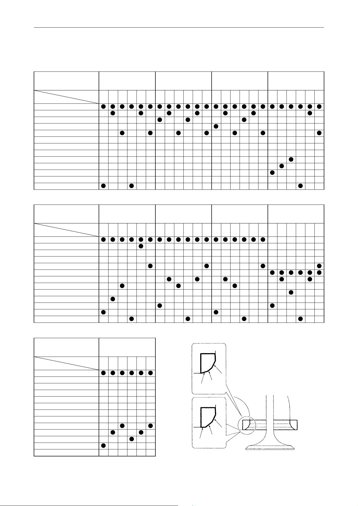
VALVE SEAT CUTTER (Refering)
APPLICATION CHART
MODEL
Part of port
TOOL No.9089006316 (ø5.5 mm holder)
06312 (45°, ø27.5 mm)
06313 (5°, ø25 mm)
06314 (5°, ø29 mm)
06315 (60°, ø26 mm)
06553 (ø6.0 mm holder)
06555 (45°, ø30 mm)
06323 (60°, ø31 mm)
06324 (60°, ø36 mm)
06325 (45°, ø35 mm)
06326 (30°, ø32.5 mm)
06327 (30°, ø35 mm) New
06328 (30°, ø27 mm)
F2.5A
In. A In. B In. C Ex. A Ex. B Ex. C In. A In. B In. C Ex. A Ex. B Ex. C In. A In. B In. C Ex. A Ex. B Ex. C In. A In. B In. C Ex. A Ex. B Ex. C
F25C
In. A In. B In. C Ex. A Ex. B Ex. C In. A In. B In. C Ex. A Ex. B Ex. C In. A In. B In. C Ex. A Ex. B Ex. C In. A In. B In. C Ex. A Ex. B Ex. C
F4A/F6A
F6B
F8C/FT8D
F50A/F60A/FT60B
FT50B/FT50C/F50D
F9.9A/F9.9B
F9.9C/F9.9D
F13.5A/F15A/F15B
F50F/FT50G/F60C/FT60D
F20A/F25A/FT25B
F30A/F40B
F75A/F75B/F80A/F90A
F90B/F100A/F100B
F100C/F115A/FL115A
MODEL
Part of port
TOOL No.9089006316 (ø5.5 mm holder)
06312 (45°, ø27.5 mm)
06313 (5°, ø25 mm)
06314 (5°, ø29 mm)
06315 (60°, ø26 mm)
06553 (ø6.0 mm holder)
06555 (45°, ø30 mm)
06323 (60°, ø31 mm)
06324 (60°, ø36 mm)
06325 (45°, ø35 mm)
06326 (30°, ø32.5 mm)
06327 (30°, ø35 mm) New
06328 (30°, ø27 mm)
F150A/F200A/FL200A
FL150A/F225A/FL225A
In. A In. B In. C Ex. A Ex. B Ex. C
1-10
C
B
A
C
B
A
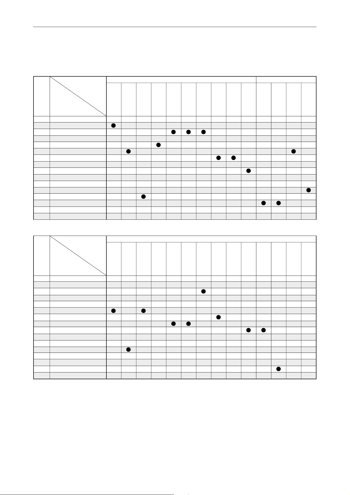
Page 20
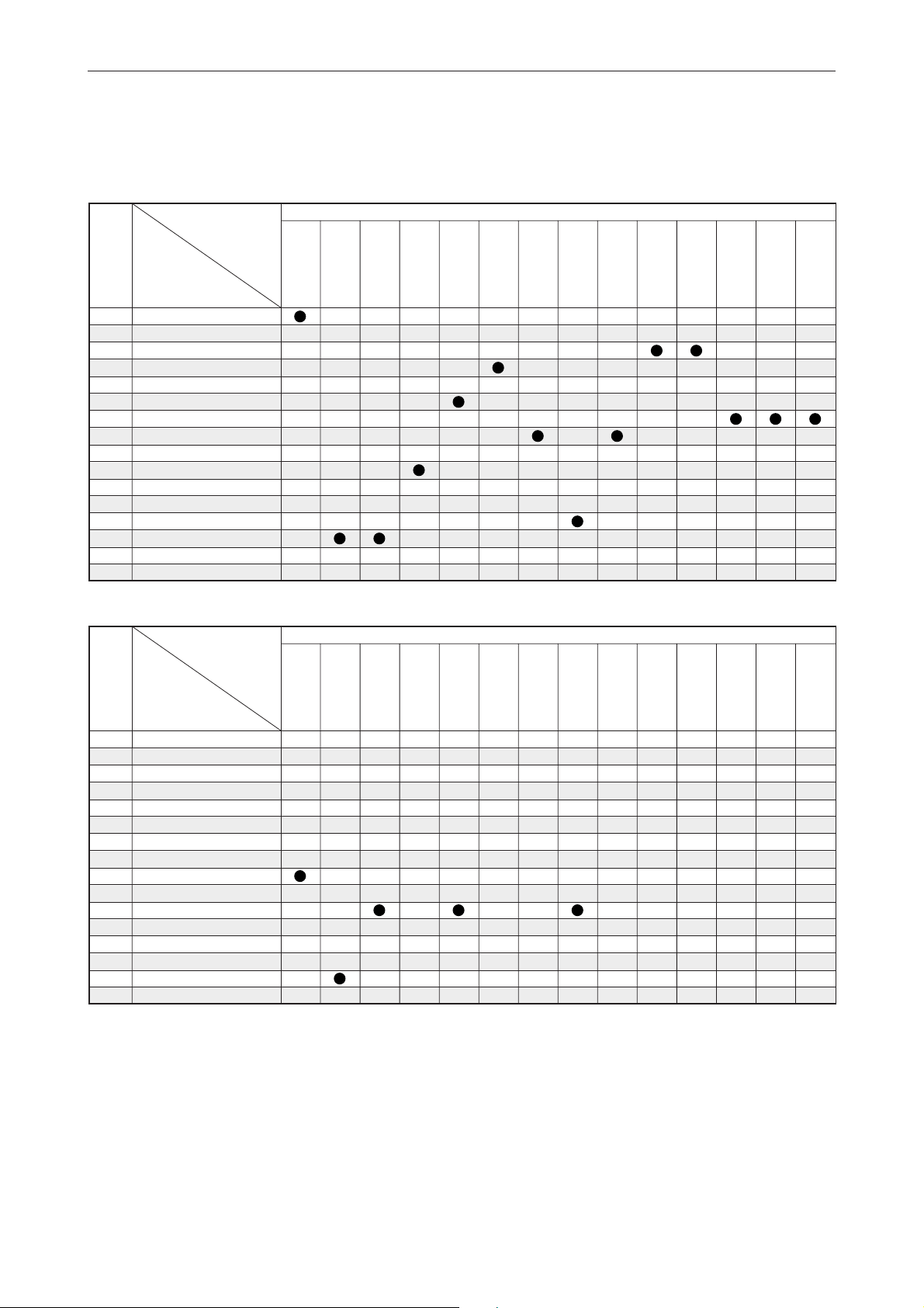
ENGINE SERVICE
(Test propeller)
(2 stroke model)
APPLICATION CHART
Tool
No.
90890-
01601
Test propeller (646)
01609
Test propeller (647)
01611
Test propeller (663)
01613
Test propeller (664)
01618
Test propeller (676)
01619
Test propeller (683)
01620
Test propeller (688)
01621
Test propeller (689)
01624
Test propeller (6E5)
01625
Test propeller (6G1)
01626
Test propeller (6G5)
01627
Test propeller (6G8)
01629
Test propeller (61N)
01630
Test propeller (6L5)
01631
Test propeller (6L6)
MODEL
MODEL
2B
3A
2C
1
L130B V6*2D150N
V4*
2 Stroke model
4AS
5C
5CS
9.9F
6C
8C
L200A
NA NA NA NA NA NA NA NA NA
13.5A
15F
150A
175A
200A
20C
2 Stroke model
L150F
L150J
L200F
L200J
20D
25N
L150A
L200A
25B
25X
30H
225C
250A
225F
250B
30D
L225C
L250A
L225F
L250B
40V
40Y
50H
Z150P
Z150Q
Z175G
Z175H
Z200N
Z200P
55B
LZ150P
LZ200N
50G
60F
70B
Z225H
Z250F
55D
75A
75B
85A
Z250D
Z300A
Z300B
75C
80A
90A
LZ250D
LZ300A
*1 V4 :115B, 115C, 130B, 140B, 140C
2
V6 :150F, 150G, 150J, 150L, 175D, 200F, 200G, 200H, 200J, 225D, 225G
*
3
Electronic fuel injectioned model only
*
4
2 stroke model
*
NA : Not availables
1-11
Page 21
(Test propeller)
(Enduro/Kerosene model, 4 stroke model)
Enduro/Kerosene model 4 Stroke model
4
40G*
E25B
E30H
E40G
EK40G
E40X
40X*
Tool
No.
90890-
01601
Test propeller (646)
01609
Test propeller (647)
01611
Test propeller (663)
01613
Test propeller (664)
01618
Test propeller (676)
01619
Test propeller (683)
01620
Test propeller (688)
01621
Test propeller (689)
01624
Test propeller (6E5)
01625
Test propeller (6G1)
01626
Test propeller (6G5)
01627
Test propeller (6G8)
01629
Test propeller (61N)
01630
Test propeller (6L5)
01631
Test propeller (6L6)
MODEL
E8D
EK8D
E9.9D
E15D
EK9.9D
EK15D
EK9.9J
EK15P
EK9.9H
EK15N
EK25B
4
40J*
K40J
4
E48C
E55C
APPLICATION CHART
E60J
E60H
K50E
E65A
E75B
E115A
F2.5A F4A
F6A
F6B
F8C
FT8D
Tool
No.
90890-
01601
Test propeller (646)
01609
Test propeller (647)
01611
Test propeller (663)
01613
Test propeller (664)
01618
Test propeller (676)
01619
Test propeller (683)
01620
Test propeller (688)
01621
Test propeller (689)
01624
Test propeller (6E5)
01625
Test propeller (6G1)
01626
Test propeller (6G5)
01627
Test propeller (6G8)
01629
Test propeller (61N)
01630
Test propeller (6L5)
01631
Test propeller (6L6)
MODEL
F9.9B FT9.9A
F9.9C
FT9.9D
F13.5A
F15A
F15B
F25C
NA
F20A
F25A
FT25B
4 Stroke model
F50A
F30A
F50D
F40B
F60A
FT50B
FT50C
FT60B
F50F
FT50G
F60C
FT60D
F75B
F90B
NA
F75A
F80A
F90A
F100A
F100B
F100C
F115A
FL115A
F150A
FL150A
NA NA
F200A
FL200A
F225A
FL225A
1-12
Page 22
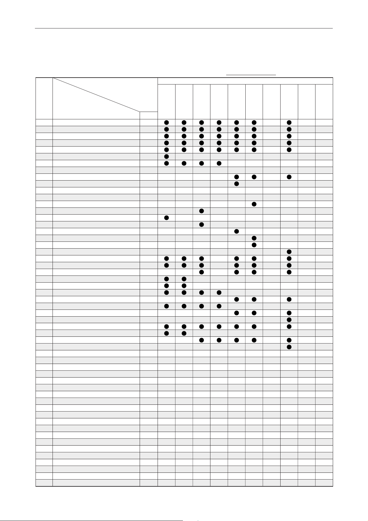
ENGINE SERVICE
(Crankshaft disassembly and reassembly)
(2 stroke model)
MODEL
Tool
No.
90890-
02422
02351
02352
02353
02354
02355
02357
02358
02359
02361
02363
02365
02366
02399
02367
02369
02371
02376
02377
02379
02384
02385
02386
02387
02388
02389
02390
02391
02392
02393
02394
02395
02396
02419
02401
02402
02403
02404
06590
Q’ty
Crank shaft jig set
• Flange
• Body
• Bolt
• Washer
• Bushing-1 (D15)
• Bushing-3 (D20)
• Bushing-4 (D22)
• Bushing-5 (D25)
• Bushing-7 (D29)
• Bushing-9 (D30)
• Bushing-1 (B11)
• Bushing-12 (D35)
• Bushing-13 (D20)
• Height ring-1 (H28)
• Height-ring-3 (H40)
• Height ring-5 (H47)
• Height ring-10 (H53)
• Height ring-5 (H54)
• Height ring-13 (H57)
• Pressure plate
• Press body
• Plate A
• Plate B
• Bolt
• Pressure pin A
• Pressure pin B
• Bearing pressure A
• Bearing pressure B
• Bearing pressure C
• Support
• Spacer A
• Spacer B
• Bushing 14 (E25A/25V)
• Height ring (E40G/J)
• Plate C
• Pressure pin C
• Spacer C
• Height ring 640 (H-19)
2B
2C
1
1
1
4
4
1
2
1
2
1
1
1
1
2
1
1
1
1
1
1
1
1
1
2
2
1
1
1
1
1
2
1
1
1
1
2
1
1
1
3A
APPLICATION CHART
The tools on these pages (1-13 and 1-14) can be ordered from
the Marine Service Division of Yamaha Motor Co., Ltd.
2 stroke model
4AC
4AS
5C
5CS
6C
8C
9.9F
13.5A
15F
20C
20D
25N
25B
25X
30H
02416
02407
02408
02409
02410
02411
02417
02412
02413
02414
02415
02418
Q’ty : The figure for this part indicates the quantity of the parts ordered in a set or a kit.
Disassembling kit
• Nut
• Pressure plate
• Pole
• Plate A
• Plate B
Assembling kit
• Guide
• Guide plate
• Guide pole
• Base
Crank separater kit (set 02416 + 02417)
1
6
1
3
1
1
1
3
1
1
1
–
1-13
Page 23
(Crankshaft disassembly and reassembly)
(Enduro/Kerosene model)
MODEL
Tool
No.
90890-
02422
02351
02352
02353
02354
02355
02357
02358
02359
02361
02363
02365
02366
02399
02367
02369
02371
02376
02377
02379
02384
02385
02386
02387
02388
02389
02390
02391
02392
02393
02394
02395
02396
02419
02401
02402
02403
02404
06590
Crank shaft jig set
• Flange
• Body
• Bolt
• Washer
• Bushing-1 (D15)
• Bushing-3 (D20)
• Bushing-4 (D22)
• Bushing-5 (D25)
• Bushing-7 (D29)
• Bushing-9 (D30)
• Bushing-1 (B11)
• Bushing-12 (D35)
• Bushing-13 (D20)
• Height ring-1 (H28)
• Height-ring-3 (H40)
• Height ring-5 (H47)
• Height ring-10 (H53)
• Height ring-5 (H54)
• Height ring-13 (H57)
• Pressure plate
• Press body
• Plate A
• Plate B
• Bolt
• Pressure pin A
• Pressure pin B
• Bearing pressure A
• Bearing pressure B
• Bearing pressure C
• Support
• Spacer A
• Spacer B
• Bushing 14 (E25A/25V)
• Height ring (E40G/J)
• Plate C
• Pressure pin C
• Spacer C
• Height ring 640 (H-19)
Q’ty
1
1
1
4
4
1
2
1
2
1
1
1
1
2
1
1
1
1
1
1
1
1
1
2
2
1
1
1
1
1
2
1
1
1
1
2
1
1
1
E8D
EK8D
EK9.9D
EK15D
EK9.9J
EK15P
EK9.9H
EK15N
E9.9D
E15D
E25B
EK25B
E30H
APPLICATION CHART
Enduro/Kerosene model
1
40G*
E40X
40X*
40J*
1
K40J
E40G
EK40G
1
E48C
E55C
E60H
K50E
02416
02407
02408
02409
02410
02411
02417
02412
02413
02414
02415
02418
*
Disassembling kit
• Nut
• Pressure plate
• Pole
• Plate A
• Plate B
Assembling kit
• Guide
• Guide plate
• Guide pole
• Base
Crank separater kit (set 02416 + 02417)
1
2 stroke model
1
6
1
3
1
1
1
3
1
1
1
–
1-14
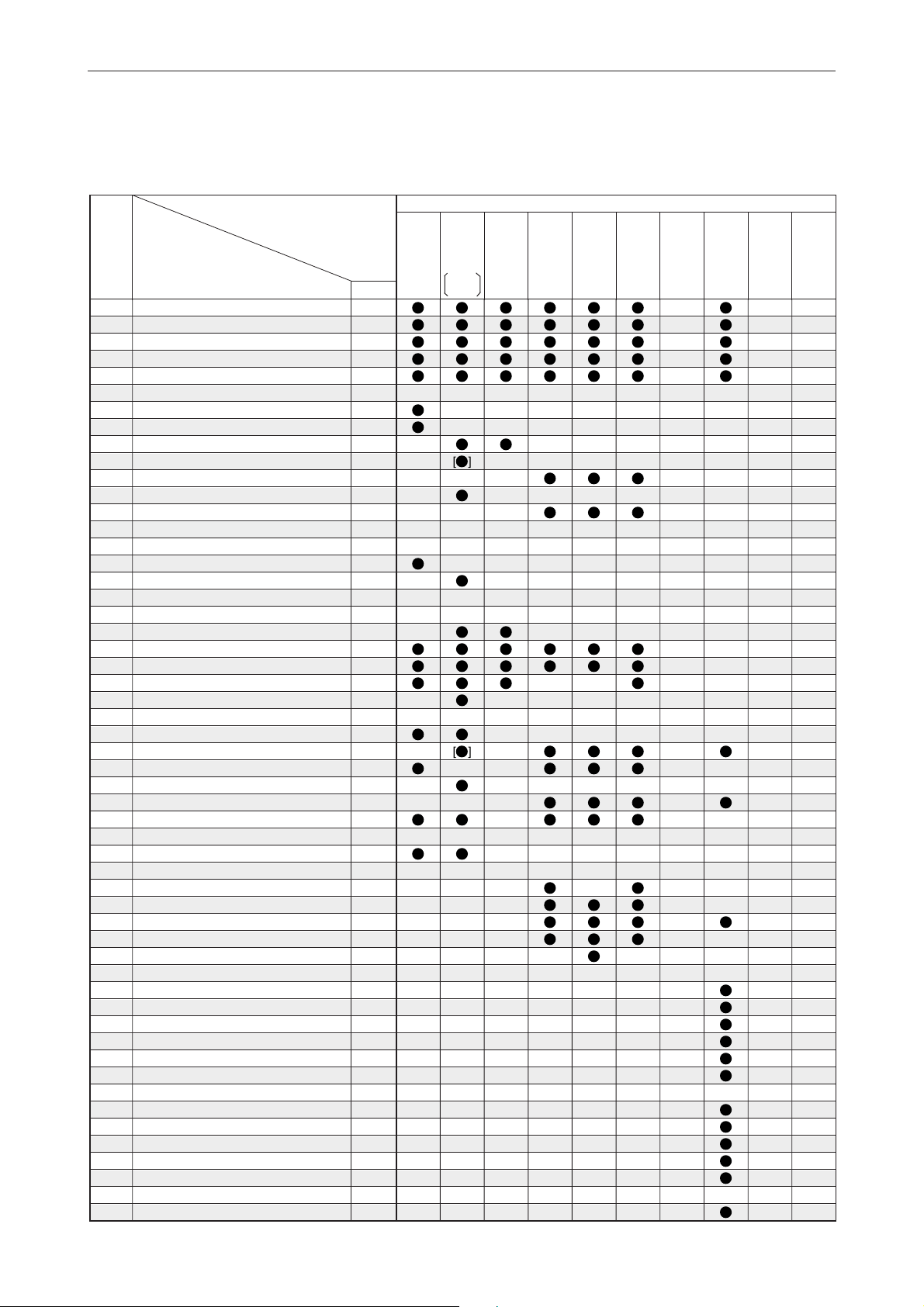
Page 24
LOWER UNIT SERVICE
(2 stroke model)
APPLICATION CHART
Tool
No.
90890-
06501
06502
06503
06564
06504
06509
06510
06511
06512
06513
06578
06715
06505
06506
06507
06508
06515
06516
06517
06518
06519
06520
06565
06534
06521
06523
06532
06533
06531
06514
06535
06536
06537
06538
06540
06601
06602
06603
06604
06605
06606
06607
06608
06609
06610
06611
06612
06613
06614
06615
06616
MODEL
Stopper guide plate
Bearing housing puller claw L
Bearing housing puller claw M
Bearing housing puller claw S
Center bolt
Ring nut wrench 1
Ring nut wrench 2
Ring nut wrench 3
Ring nut wrench 4
Ring nut wrench extension
Ring nut wrench
Pinion nut holder
Pinion nut holder
• Socket adapter 1
• Socket adapter 2
• Socket adapter 3
Drive shaft holder 1
Drive shaft holder 2
Drive shaft holder 3
Drive shaft holder 4
Drive shaft holder 5
Drive shaft holder 6
Drive shaft holder 7
Bearing separator
Flywheel puller
Bearing outer race puller assembly
• Outer race puller claw A
Outer race puller claw B
Slide hammer handle
Puller head
Bearing puller assembly
• Bearing puller claw 1
• Bearing puller claw 2
Stopper guide stand
Gear puller
Bushing installer center bolt
Driver rod SL
Bearing depth plate
Driver rod SS
Driver rod LL
Driver rod LS
Needle bearing attachment
Needle bearing attachment
Needle bearing attachment
Needle bearing attachment
Needle bearing attachment
Needle bearing attachment
Needle bearing attachment
Needle bearing attachment
Needle bearing attachment
Needle bearing attachment
2B
2C
3A
4AC
4AS
5C
5CS
6C
8C
9.9F
13.5A
15F
2 Stroke model
20D
20C
25N
25B
25X
30H
30D
40V
40Y
50H
55B
50G
60F
70B
1
*
V4 :115B, 115C, 130B, 140B, 140C
2
*
V6 :150F, 150G, 150J, 150L, 175D, 200F,
200G, 200H, 200J, 225D, 225G
1-15
3
Electronic fuel injectioned model only
*
4
*
2 stroke model
5
Apply pressure to outer propeller shaft
*
Page 25
55D
75A
75B
85A
75C
80A
90A
V4*
1
L130B
V6*2D150N
150A
175A
200A
L150F
L150J
L200F
L200J
225C
250A
225F
250B
L225C
L250A
L225F
L250B
Z150P
Z150Q
Z175G
Z175H
Z200N
Z200P
LZ150P
LZ200N
Z225H
Z250F
Z250D
Z300A
Z300B
LZ250D
LZ300A
L150A
L200A
2 Stroke model
Tool
No.
90890-
06501
06502
06503
06564
06504
06509
06510
06511
06512
06513
06578
06715
06505
06506
06507
06508
06515
06516
06517
06518
06519
06520
06565
06534
06521
06523
06532
06533
06531
06514
06535
06536
06537
06538
06540
06601
06602
06603
06604
06605
06606
06607
06608
06609
06610
06611
06612
06613
06614
06615
06616
1-16
APPLICATION CHART
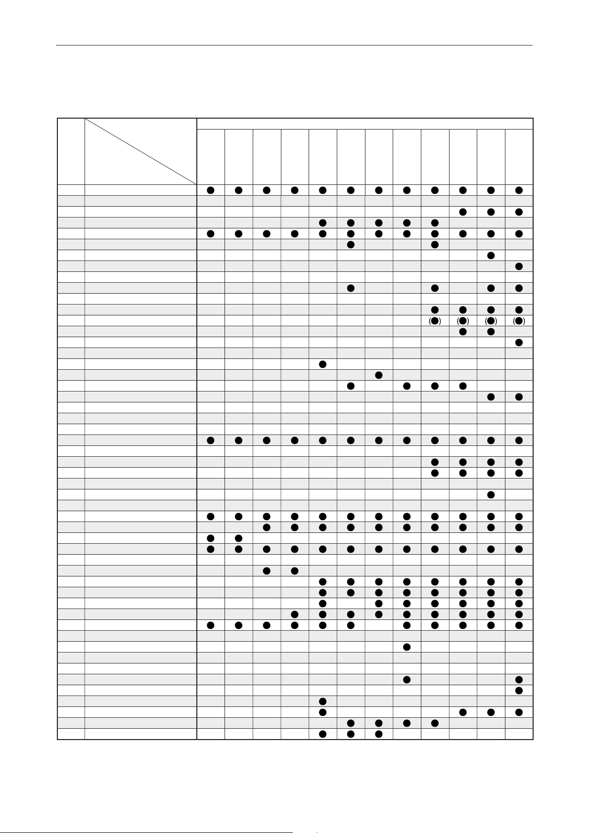
Page 26
APPLICATION CHART
Tool
No.
90890-
06617
Needle bearing attachment
06618
Needle bearing attachment
06619
Bearing outer race attachment
06620
Bearing outer race attachment
06621
Bearing outer race attachment
06622
Bearing outer race attachment
06623
Bearing outer race attachment
06624
Bearing outer race attachment
06625
Bearing outer race attachment
06626
Bearing outer race attachment
06627
Bearing outer race attachment
06628
Bearing outer race attachment
06629
Ball bearing attachment
06630
Ball bearing attachment
06631
Ball bearing attachment
06632
Ball bearing attachment
06633
Ball bearing attachment
06634
Ball bearing attachment
06635
Ball bearing attachment
06636
Ball bearing attachment
06637
Ball bearing attachment
06638
Ball bearing attachment
06639
Bearing inner race attachment
06640
Bearing inner race attachment
06641
Bearing inner race attachment
06642
Bearing inner race attachment
06643
Bearing inner race attachment
06644
Bearing inner race attachment
06645
Bearing inner race attachment
06646
Bushing puller center bolt
06648
Bushing puller spacer
06649
Bushing attachment
06650
Bushing attachment
06651
Bushing attachment
06652
Driver rod L3
06653
Needle bearing attachment
06654
Needle bearing attachment
06655
Ball bearing attachment
06656
Ball bearing attachment
06657
Ball bearing attachment
06658
Bearing outer race attachment
06659
Bearing inner race attachment
06660
Bearing inner race attachment
06661
Bearing inner race attachment
06662
Bearing inner race attachment
MODEL
2B
2C
3A
4AC
4AS
5C
5CS
6C
8C
9.9F
13.5A
15F
2 Stroke model
20D
20C
25N
25B
25X
30H
30D
40V
40Y
50H
55B
50G
60F
70B
06052
Shift rod push arm
YB-42223
Gland nut wrench
YB-42224
Pinion nut wrench
1
*
V4 :115B, 115C, 130B, 140B, 140C
2
*
V6 :150F, 150G, 150J, 150L, 175D, 200F, 200G, 200H, 200J, 225D, 225G
3
*
Electronic fuel injectioned model only
4
*
2 stroke model
5
*
Apply pressure to outer propeller shaft
1-17
Page 27

Tool
No.
90890-
06617
06618
06619
06620
06621
06622
06623
06624
06625
06626
06627
06628
06629
06630
06631
06632
06633
06634
06635
06636
06637
06638
06639
06640
06641
06642
06643
06644
06645
06646
06648
06649
06650
06651
06652
06653
06654
06655
06656
06657
06658
06659
06660
06661
06662
55D
75A
75B
85A
75C
80A
90A
V4*
1
L130B
V6*2D150N
150A
175A
200A
2 Stroke model
L150F
L150J
L150A
L200F
L200A
L200J
225C
250A
225F
250B
APPLICATION CHART
Z150P
L225C
L250A
L225F
L250B
Z150Q
Z175G
Z175H
Z200N
Z200P
LZ150P
LZ200N
Z250F
Z225H
Z250D
Z300A
Z300B
LZ250D
LZ300A
06052
YB-42223
YB-42224
1-18
Page 28

LOWER UNIT SERVICE
(Enduro/Kerosene model, 4 stroke model)
APPLICATION CHART
Tool
No.
90890-
06501
Stopper guide plate
06502
Bearing housing puller claw L
06503
Bearing housing puller claw M
06564
Bearing housing puller claw S
06504
Center bolt
06509
Ring nut wrench 1
06510
Ring nut wrench 2
06511
Ring nut wrench 3
06512
Ring nut wrench 4
06513
Ring nut wrench extension
06578
Ring nut wrench
06715
Pinion nut holder
06505
Pinion nut holder
06506
• Socket adapter 1
06507
• Socket adapter 2
06508
• Socket adapter 3
06515
Drive shaft holder 1
06516
Drive shaft holder 2
06517
Drive shaft holder 3
06518
Drive shaft holder 4
06519
Drive shaft holder 5
06520
Drive shaft holder 6
06565
Drive shaft holder 7
06534
Bearing separator
06521
Flywheel puller
06523
Bearing outer race puller assembly
06532
• Outer race puller claw A
06533
Outer race puller claw B
06531
Slide hammer handle
06514
Puller head
06535
Bearing puller assembly
06536
• Bearing puller claw 1
06537
• Bearing puller claw 2
06538
Stopper guide stand
06540
Gear puller
06601
Bushing installer center bolt
06602
Driver rod SL
06603
Bearing depth plate
06604
Driver rod SS
06605
Driver rod LL
06606
Driver rod LS
06607
Needle bearing attachment
06608
Needle bearing attachment
06609
Needle bearing attachment
06610
Needle bearing attachment
06611
Needle bearing attachment
06612
Needle bearing attachment
06613
Needle bearing attachment
06614
Needle bearing attachment
06615
Needle bearing attachment
06616
Needle bearing attachment
MODEL
E8D
E8DK
E9.9D
E15D
EK9.9D
EK15D
EK9.9J
EK15P
EK9.9H
EK15N
Enduro/Kerosene model 4 Stroke model
4
E25B
EK25B
E30H
40G*
E40G
EK40G
E40X
40X*
4
40J*
K40J
4
E48C
E55C
E60H
K50E
E60J
E65A
E75B
E115A
F2.5A
F4A
F6A
F6B
F8C
1
*
V4 :115B, 115C, 130B, 140B, 140C
2
*
V6 :150F, 150G, 150J, 150L, 175D, 200F,
200G, 200H, 200J, 225D, 225G
1-19
3
*
Electronic fuel injectioned model only
4
*
2 stroke model
5
*
Apply pressure to outer propeller shaft
Page 29

Tool
No.
FT8D F9.9B F15B F25C
90890-
06501
06502
06503
06564
06504
06509
06510
06511
06512
06513
06578
06715
06505
06506
06507
06508
06515
06516
06517
06518
06519
06520
06565
06534
06521
06523
06532
06533
06531
06514
06535
06536
06537
06538
06540
06601
06602
06603
06604
06605
06606
06607
06608
06609
06610
06611
06612
06613
06614
06615
06616
FT9.9A
F9.9C
FT9.9D
F13.5A
F15A
F20A
F25A
[FT25B]
F30A
F40B
4 Stroke model
F50A
F50F
F50D
F60C
F60A
FT50B
FT50C
[FT60B]
FT50G
[FT60D]
F75A
F80A
F90A
F100A
F100B
F100C
APPLICATION CHART
F75B
F90B
F115A
FL115A
F150A
FL150A
F200A
F225A
FL200A
FL225A
1-20
Page 30

APPLICATION CHART
Tool
No.
90890-
06617
Needle bearing attachment
06618
Needle bearing attachment
06619
Bearing outer race attachment
06620
Bearing outer race attachment
06621
Bearing outer race attachment
06622
Bearing outer race attachment
06623
Bearing outer race attachment
06624
Bearing outer race attachment
06625
Bearing outer race attachment
06626
Bearing outer race attachment
06627
Bearing outer race attachment
06628
Bearing outer race attachment
06629
Ball bearing attachment
06630
Ball bearing attachment
06631
Ball bearing attachment
06632
Ball bearing attachment
06633
Ball bearing attachment
06634
Ball bearing attachment
06635
Ball bearing attachment
06636
Ball bearing attachment
06637
Ball bearing attachment
06638
Ball bearing attachment
06639
Bearing inner race attachment
06640
Bearing inner race attachment
06641
Bearing inner race attachment
06642
Bearing inner race attachment
06643
Bearing inner race attachment
06644
Bearing inner race attachment
06645
Bearing inner race attachment
06646
Bushing puller center bolt
06648
Bushing puller spacer
06649
Bushing attachment
06650
Bushing attachment
06651
Bushing attachment
06652
Driver rod L3
06653
Needle bearing attachment
06654
Needle bearing attachment
06655
Ball bearing attachment
06656
Ball bearing attachment
06657
Ball bearing attachment
06658
Bearing outer race attachment
06659
Bearing inner race attachment
06660
Bearing inner race attachment
06661
Bearing inner race attachment
06662
Bearing inner race attachment
MODEL
E8D
E8DK
E9.9D
E15D
EK9.9D
EK15D
EK9.9J
EK15P
EK9.9H
EK15N
Enduro/Kerosene model 4 Stroke model
4
40G*
E25B
EK25B
E30H
E40G
EK40G
E40X
40X*
4
40J*
K40J
4
E48C
E55C
E60H
K50E
E60J
E65A
E75B
E115A
F2.5A
F4A
F6A
F6B
F8C
06052
Shift rod push arm
Gland nut wrench
YB-42223
Pinion nut wrench
YB-42224
1
*
V4 :115B, 115C, 130B, 140B, 140C
2
*
V6 :150F, 150G, 150J, 150L, 175D, 200F, 200G, 200H, 200J, 225D, 225G
3
Electronic fuel injectioned model only
*
4
2 stroke model
*
5
*
Apply pressure to outer propeller shaft
1-21
Page 31

4 Stroke model
Tool
No.
90890-
FT8D F15B F25CF9.9B
FT9.9A
F9.9C
FT9.9D
F13.5A
F15A
F20A
F25A
F50F
F60C
F75B
F90B
FT50G
FT60D
F50A
F50D
F60A
FT50B
FT50C
FT60B
F75A
F80A
F90A
F100A
F100B
F100C
F115A
FL115A
F150A
FL150A
FT25B
F30A
F40B
F200A
F225A
FL200A
FL225A
06617
06618
06619
06620
06621
06622
06623
06624
06625
06626
06627
06628
06629
06630
06631
06632
06633
06634
06635
06636
06637
06638
06639
06640
06641
06642
06643
06644
06645
06646
06648
06649
06650
06651
06652
06653
06654
06655
06656
06657
06658
06659
06660
06661
06662
06052
YB-42223
YB-42224
APPLICATION CHART
1-22
Page 32

SHIM SELECTION / PTT TOOL
(2 stroke model)
APPLICATION CHART
Tool
No.
90890-
SHIM SELECTION
06701
06710
06711
06712
06703
06704
06844
06706
07003
01252
PTT TOOL
06568
(06544)
06587
(06548)
06588
06773
06774
06776
06560
06580
06581
06569
06572
Shimming plate
Pinion height gauge
• Pinion height gauge plate A
Pinion height gauge plate B
Pinion height plate
Digital caliper
Magnet base
Backlash indicator
Magnet base plate
Dial gauge set
Cylinder-end screw wrench
Cylinder-end screw wrench
Trim & tilt wrench
Trim & tilt wrench
PTT wrench 46
Up relief fitting
Down relief fitting
Hydraulic pressure gauge
Power tilt wrench
PTT oil pressure gauge assembly
PTT oil pressure gauge adapter
Title rod wrench
PTT piston vice attachment
MODEL
2B
2C
3A
4AC
4AS
5C
5CS
6C
8C
9.9F
13.5A
15F
2 Stroke model
20D
20C
25N
25B
25X
30H
30D
40V
40Y
50H
55B
50G
60F
70B
1
*
V4 :115B, 115C, 130B, 140B, 140C
2
V6 :150F, 150G, 150J, 150L, 175D, 200F, 200G, 200H, 200J, 225D, 225G
*
1-23
Page 33

Tool
No.
90890-
06701
06710
06711
06712
06703
06704
06844
06706
07003
01252
06568
(06544)
06587
(06548)
06588
06773
06774
06776
06560
06580
06581
06569
06572
55D
75A
75B
85A
75C
80A
90A
V4*
1
L130B
V6*2D150N
150A
175A
200A
2 Stroke model
L150F
L150A
L150J
L200A
L200F
L200J
225C
250A
225F
250B
APPLICATION CHART
Z150P
L225C
L250A
L225F
L250B
Z150Q
Z175G
Z175H
Z200N
Z200P
LZ150P
LZ200N
Z225H
Z250F
Z250D
Z300A
Z300B
LZ250D
LZ300A
1-24
Page 34

SHIM SELECTION / PTT TOOL
(Enduro/Kerosene model, 4 stroke model)
APPLICATION CHART
Tool
No.
90890-
SHIM SELECTION
06701
06710
06711
06712
06703
06704
06844
06706
07003
01252
Shimming plate
Pinion height gauge
• Pinion height gauge plate A
Pinion height gauge plate B
Pinion height plate
Digital caliper
Magnet base
Backlash indicator
Magnet base plate
Dial gauge set
PTT TOOL
06568
(06544)
06587
(06548)
06588
06773
06774
06776
06560
06580
06581
06569
06572
Cylinder-end screw wrench
Cylinder-end screw wrench
Trim & tilt wrench
Trim & tilt wrench
PTT wrench 46
Up relief fitting
Down relief fitting
Hydraulic pressure gauge
Power tilt wrench
PTT oil pressure gauge assembly
PTT oil pressure gauge adapter
Title rod wrench
PTT piston vice attachment
MODEL
E8D
E8DK
E9.9D
E15D
EK9.9D
EK15D
EK9.9J
EK15P
EK9.9H
EK15N
Enduro/Kerosene model 4 Stroke model
1
40G*
E25B
EK25B
E30H
E40G
EK40G
E40X
40X*
1
40J*
K40J
1
E48C
E55C
E60H
K50E
E60J
E65A
E75B
E115A
F2.5A
F4A
F6A
F6B
F8C
1
*
2 stroke model
1-25
Page 35

Tool
No.
90890-
06701
06710
06711
06712
06703
06704
06844
06706
07003
01252
06568
(06544)
06587
(06548)
06588
06773
06774
06776
06560
06580
06581
06569
06572
FT8D F25CF15BF9.9B
FT9.9A
F9.9C
FT9.9D
F13.5A
F15A
F20A
F25A
FT25B
F30A
F40B
4 Stroke model
F50A
F50F
F50D
F60C
F60A
FT50B
FT50C
[FT60B]
FT50G
[FT60D]
F75A
F80A
F90A
F100A
F100B
F100C
APPLICATION CHART
F75B
F90B
F115A
FL115A
F150A
FL150A
F200A
F225A
FL200A
FL225A
1-26
Page 36

WATERCRAFT TOOL
MEASURING TOOL/PEAK VOLTAGE MEASUREMENT
ENGINE SERVICE
APPLICATION CHART
Tool
No.
90890-
MEASURING TOOL/PEAK VOLTAGE MEASUREMENT
01252
06585
06584
06583
03006
03007
03008
03009
03010
06759
03180
03112
03174
03160
06582
06786
06842
06754
06756
06760
03172
06769
06867 (06767)
06871 (06771)
06877 (06777)
06878 (06778)
06879 (06779)
06880 (06780)
06870 (06770)
06790
06791
06792
06793
06848
06849
06862
01080
60V-85300-02
60V-WS853-02
ENGINE SERVICE
06521
06522
06550
06534
06425
06546
06551
06606
06624
06626
Tool name
Dial gauge set
Dial gauge stand set
• Dial gauge needle 173
• Dial gauge stand 173
Outside micrometer 0 - 25
Outside micrometer 25 - 50
Outside micrometer 50 - 75
Outside micrometer 75 - 100
Inside micrometer 5 - 25
Cylinder gauge 50 - 100
Thickness gauge
Pocket tester
Digital circuit tester
Compression gauge
Compression gauge extension M10
Fuel pressure gauge
Fuel pressure gauge adapter
Ignition tester
Vacuum/ presure pump gauge set
Digital tachometer
Peak voltage adapter B
Test harness EJ-II-3
Test harness FWY-2
Test harness FWY-4
Test harness HM090-3
Test harness 090-4
Test harness FWY-8
Test harness SMT618-6
Test harness SMT250-3
Test harness FSW-6
Test harness FWY-3-L
Test harness SMHW090-2
Test harness SMHW090-3
Test harness FSW-6A
Test harness SM6195021-6
Test connector FMY-8
Rotor puller
Yamaha Diagnostic System (KIT)
Yamaha Diagnostic System (CD-ROM) *2
Flywheel puller
Flywheel holder
Flywheel holder
Bearing separator
Coupler wrench
Coupler wrench
Coupler wrench
Driver rod LS
Bearing outer race attachment
Bearing outer race attachment
MODEL
FX700
SJ700A
WB700A
WB760 WB800
WVT700B
XL700 XL760 XL800
XL800A
*1 Available separately (set 06585=06584+06583)
2
Up-date CD-ROM only
*
1-27
Page 37

APPLICATION CHART
Tool
No.
90890-
01252
06585
06584
06583
03006
03007
03008
03009
03010
06759
03180
03112
03174
03160
06582
06786
06842
06754
06756
06760
03172
06769
06867 (06767)
06871 (06771)
06877 (06777)
06878 (06778)
06879 (06779)
06880 (06780)
06870 (06770)
06790
06791
06792
06793
06848
06849
06862
01080
60V-85300-02
60V-WS853-02
XLT800
XL1200
XL1200Ltd
XLT1200
GP760
GP800
GP800R GP1200
GP1200R
GP1300R
EXT1200
EXS1200
SUV1200
SUV1200Z
FX140/
Cruiser
FX160/
Cruiser
06521
06522
06550
06534
06425
06546
06551
06606
06624
06626
1-28
Page 38

ENGINE SERVICE/JET PUMP SERVICE
APPLICATION CHART
Tool
No.
90890-
Tool name
ENGINE SERVICE
01426
Oil filter wrench 64
01701
Sheave holder
01235
Rotor holder
03094
Vacuum gauge [Selector type]
03060
• Attachment
06586
Shaft holder
06756
Vacuum/pressure pump gauge set
04019
Valve spring compressor
04108
Valve spring compressor attachment
04114
Valve spring compressor attachment
04111
Valve guide remover 4.0
04116
Valve guide remover 4.5
04112
Valve guide installer 4.0
04117
Valve guide installer 4.5
04113
Valve guide reamer 4.0
04118
Valve guide reamer 4.5
06811
Valve seat cutter holder ø 4.0
06812
Valve seat cutter holder ø 4.5
06328
Valve seat cutter 30°-27
06815
Valve seat cutter 30°-24
06312
Valve seat cutter 45°-27.5
06814
Valve seat cutter 45°-24
06315
Valve seat cutter 60°-26
06813
Valve seat cutter 60°-22
05158
Piston ring compressor
JET PUMP SERVICE
06069
Shaft holder
06552
Crankshaft holder 20
06518
Drive shaft holder 4
06519
Drive shaft holder 5
06425
Coupler wrench
06546
Coupler wrench
06551
Coupler wrench
06523
Bearing outer race puller assembly
06531
Slide hammer handle
06602
Driver rod SL
06605
Driver rod LL
06606
Driver rod LS
06652
Driver rod L3
06653
Needle bearing attachment
06611
Needle bearing attachment
06613
Needle bearing attachment
06614
Needle bearing attachment
06631
Ball bearing attachment
06634
Ball bearing attachment
06638
Ball bearing attachment
06636
Ball bearing attachment
06657
Ball bearing attachment
06625
Bearing outer race attachment
06626
Bearing outer race attachment
06662
Bearing inner race attachment
06501
Stopper guide plate
06535
Bearing puller assembly
06538
Stopper guide stand
06536
Bearing puller crow 1
06704
Digital caliper
MODEL
FX700
SJ700A
WB700A
WB760 WB800
WVT700B
XL700 XL760 XL800
XL800A
1-29
Page 39

APPLICATION CHART
Tool
No.
90890-
01426
01701
01235
03094
03060
06586
06756
04019
04108
04114
04111
04116
04112
04117
04113
04118
06811
06812
06328
06815
06312
06814
06315
06813
05158
XLT800
XL1200
XL1200Ltd
XLT1200
GP760 GP800
GP800R GP1200
GP1200R
GP1300R
EXT1200
EXS1200 SUV1200
SUV1200Z
FX140/
Cruiser
FX160/
Cruiser
06069
06552
06518
06519
06425
06546
06551
06523
06531
06602
06605
06606
06652
06653
06611
06613
06614
06631
06634
06638
06636
06657
06625
06626
06662
06501
06535
06538
06536
06704
1-30
Page 40

MEASURING TOOL
TOOL DESCRIPTION
Tool No.
90890-
Tool name Usage Note
06760 Digital tachometer
03141 Timing light
06754 Ignition tester
(Spark gap tester)
03160 Compression gauge Plug type:
B, C & D
0—1500 kPa
06563 Compression gauge
extension M14
06582 Compression gauge
extension M10
06563
d1:M14S
d2:19
L1:135
06582
d1:M10S
d2:14
d2
L1
d1
L1:165
2-1
Page 41

TOOL DESCRIPTION
Tool No.
90890-
Tool name Usage Note
06840 Leakage tester
06786 Fuel pressure gauge
06785 • Mouth feel rubber
06942 Fuel pressure gauge
adapter B
0—250 kPa
0—600 kPa
06785
Q ty=3pcs/pack
use with 06786
06942
06842 Fuel pressure gauge
adapter
06756 Vacuum/pressure
pump gauge set
use with 06786
06786
Vacuum
0—(-100) kPa
Pressure
0—50 kPa
2-2
Page 42

TOOL DESCRIPTION
Tool No.
90890-
Tool name Usage Note
03159 Vacuum gauge
03094 Vacuum gauge
[Selector type]
03060
• Attachment
d1
0—760 mmHg
0—(-100) kPa
Selector type
03060 (1 pc)
d1: M6
L
d2
d2: 4
L: 42
0—150 mm06704 Digital caliper
01252 Dial gauge set
06585 Dial gauge stand set
06583 • Dial gauge stand 173
06584 • Dial gauge needle 173
A
L: 173
L: 173
2-3
Page 43

TOOL DESCRIPTION
Tool No.
90890-
06844 Magnet base B
03107 Crankshaft aligner
03016
06759
Tool name Usage Note
Cylinder gauge 35 - 60
Cylinder gauge 50 - 100
03016
35—60 mm
03006
03007
03008
03009
03010 Inside micrometer
Outside micrometer 0-25
Outside micrometer 25-50
Outside micrometer 50-75
Outside micrometer 75-100
5 - 25
06759
50—100 mm
Use with
dial gauge
01252
03006
0—25 mm
03007
25—50 mm
03008
50—75 mm
03009
75—100 mm
5—25 mm
2-4
Page 44

TOOL DESCRIPTION
Tool No.
90890-
Tool name Usage Note
03180 Thickness gauge
(Feeler gauge)
B1
B2
L
01399 Special thickness
gauge
0.20
0.15
0.05
0.02
0.03
0.10
0.25
03112 Pocket tester
0.03, 0.05, 0.10
0.15, 0.20, 0.25
0.30, 0.35, 0.40
0.50
L: 75
B1: 6.0
B2: 12.7
03174 Digital circuit tester
03172 Peak voltage
adapter B
Connector
Test harness
2-5
03174
03172
Page 45

TOOL DESCRIPTION
Tool No.
90890-
Tool name Usage Note
06862 Test connector FMY-8
06757 Throttle sensor
adjusting lead FWY-3
06865 Diagnostic flash
indicator B
250A
225C
ROPROP
250B
225F
L:150
ROP
L:3 m
for 2 & 4 stroke
Replaces 06765
(previous tool
for 2 stroke)
06765 06865
06864 Diagnostic flash adap-
ter
60V-85300-02
Yamaha Diagnostic System (KIT)
60V-WS853-02
Yamaha Diagnostic System (CD-ROM)
1
*
Up-date CD-ROM only
1
*
06765
2-6
L/W
L
for 4 stroke
model with
06765 (previous
tool for 2 stroke)
L
Y
L
G/Y
R/B,W/B,B
G/Y
G
Contents
1. Software
2. Adapter
Communication
3.
cable (USB)
4. Instruction
Manual
Page 46

Tool No.
Tool name
9089006846 Test harness
QLW-3
06847 Test harness
QLWD-3
06848 Test harness
FSW-6A
03174
03172
Connector
06857 Throttle sensor
adjusting lead
FWY-3
(06757)
06867
(06767)
Test harness
FWY-2
06868
(06768)
Test harness
EJ-II-2
06869
(06769)
Test harness
EJ-II-3
06870
(06770)
Test harness
SMT250-3
06871
(06771)
Test harness
FWY-4
06872
(06772)
Test harness
FWY-6
06875
(06775)
Test harness
AMP-4
06877
(06777)
Test harness
HM090-3
06878
(06778)
Test harness
090-4
06879
(06779)
Test harness
FWY-8
06880
(06780)
Test harness
SMT618-6
06887
(06787)
Test harness
FW13613-2
06888
(06788)
Test harness
FW13613-1
06790 Test harness
FSW-6
06791 Test harness
FWY-3-L
06792 Test harness
SMHW090-2
06793 Test harness
SMHW099-3
06861 Test harness
SM6195043
06849 Test harness
SM6195021-6
Usage
PEAK VOLTAGE MEASUREMENT
TOOL DESCRIPTION
2-7
Page 47

ENGINE SERVICE
TOOL DESCRIPTION
Tool No.
90890-
Tool name Usage Note
06521 Flywheel puller
06901 • Bolt M8
06902 • Bolt M6
06522 Flywheel holder
Small end bearing
installer
06524
06525
06526
06527
06528
06543
Bolt
5/8-18UNF
06901
X
1.25
M8
L: 34.0
: 12
06902
X
1.0
X
34
X
24
D1
12.0
16.0
18.0
20.0
21.5
14.0
L1
13.0
13.0
13.0
17.0
19.0
13.0
M6
L: 24.0
: 12
06529
06530
06843
Piston slider ø70
Piston slider ø85
Piston slider ø58
ø: Standard set diameter
05158 Piston ring
compressor
06529
ø: 70 (min ø59)
06530
ø: 85 (min ø75)
06843
ø: 58 (min ø49)
ø: 60—115
2-8
Page 48

TOOL DESCRIPTION
Tool No.
90890-
06534 Bearing separator
06606 Driver rod LS
06663 Ball bearing
Tool name Usage Note
attachment
(Roller bearing installer)
W: 25 X 107
d1: M10
L1: 101.0
d1: 5/8-18UNF
D1: 51.8
D2: 40
d1: 5/8-18UNF
L1: 13
L2: 5
X
1.25
01235 Rotor holder
04086
Universal clutch holder
2-9
Page 49

TOOL DESCRIPTION
Tool No.
90890-
Tool name Usage Note
01701 Sheave holder
01080 Rotor puller
M16xP1.5
06069 Shaft holder Double shaft
06355
06552
06561
06562
Crankshaft holder 16
Crankshaft holder 20
Crankshaft holder 12
Crankshaft holder 18
Sprine
X
n: 18 X 16
D
X
n: 13 X 11
D
Sprine
06355
X
n: 16 X 14
D
06552
X
n: 20 X 18
D
06561
D
X
n: 12 X 10
06562
X
n: 18 X 16
D
2-10
Page 50

TOOL DESCRIPTION
Tool No. Tool name Usage Note
G1—G4 *1Deep socket 1—4
LS
1
G5 *
T-type TORX socket
T55
1
G6 *
E-type TORX socket
E10
G1, S X L: 30 X 100
G2, S
X
L: 36 X 100
G3, S
X
G1
-
G4
G4, S
L: 41 X 100
X
L: 46 X 100
T55
A: 11.22
G5
G5
A
E10
A: 9.42
1
G7 *
G8 *
1
TORX tamper resistant driver T20
TORX tamper resistant driver T25
A
06991 Injector grease
A
G6
T20
A: 3.86
T20
T25
A: 4.43
T25
for H.P.D.I. model
1
*
G1-G8: General tool
2-11
Page 51

TOOL DESCRIPTION
Tool No.
90890-
06639
06640
06641
06642
06643
06644
06645
06659
06660
06661
06662
Tool name Usage Note
Bearing inner race
attachment
D1
48.5
44.5
43.0
41.0
40.0
38.0
32.5
70.0
64.0
61.0
58.0
D2
42.5
38.5
37.0
34.5
33.5
31.5
26.5
65.0
60.0
55.0
52.0
D3
36.5
32.5
30.5
28.5
27.5
25.5
20.5
55.0
50.5
45.0
42.5
L1
27.0
24.0
24.0
22.0
22.0
21.0
18.0
37.0
37.0
35.0
33.0
L2
21.0
19.0
19.0
17.0
17.0
16.0
13.0
30.0
30.0
28.0
26.0
2-12
Page 52

4 stroke
Tool No.
Tool name Usage Note
90890-
01426
06830
Oil filter wrench 64
Oil filter wrench 72.5
04019 Valve spring
compressor
01426
W: 64
06830
W: 72.5
L1: 45
L2: 22
D1: 31.0
D2: 28.4
L3: 5
D3: 32.1
D4: 16
04108
L1: 45
L2: 26
D1: 19.8
D2: 14
04114
L1: 43
L2: 26
D1: 19
D2: 17
Valve spring
compressor
attachment
06320
L1: 45
L2: 26
D1: 23.3
D2: 17
04108
04114
06320
L1
L2
D2
D1
L1
L2
L3
D2
D3
D4
D1
TOOL DESCRIPTION
2-13
Page 53

TOOL DESCRIPTION
Tool No.
90890-
06801
04064
04111
04116
06802
04015
06810
04112
04117
06804
04066
04113
04118
Tool name Usage Note
Valve guide
remover/installer 5.4
Valve guide
remover/installer 5.9
Valve guide remover 4.0
Valve guide remover 4.5
Valve guide installer 5.4
Valve guide installer 5.6
Valve guide installer 5.5
Valve guide installer 4.0
Valve guide installer 4.5
Valve guide reamer 5.5
Valve guide reamer 6.0
Valve guide reamer 4.0
Valve guide reamer 4.5
06802
L2: 13
D3: 5.4
D4: 9.2
D5: 12.0
H: 8.1
04015
L2: 25
D3: 5.6
D4: 12.5
D5: 15.1
H: —
06801
L1: 40.0
D1: 9.0
D2: 5.4
04064
L1: 45
D1: 10
D2: 5.9
06810
L2: 22
D3: 5.5
D4: 9.9
D5: 12.0
H: —
04112
L2: 25
D3: 4.0
D4: 7.35
D5: 9.1
H: 7.35
06804
L3: 65
D6: 5.5
04066
L3: 65
D6: 6.0
04111
L1: 30.0
D1: 9.0
D2: 4.0
04116
L1: 30.0
D1: 9.0
D2: 4.5
04117
L2: 22
D3: 4.5
D4: 8.3
D5: 10.0
H: 7.0
04113
L3: 53
D6: 4.0
04118
L3: 45
D6: 4.5
05041 Tap handle (5–6)
04101 Valve lapper
05041
for 5–6 mm
L: 145
D: 14
2-14
Page 54

TOOL DESCRIPTION
Tool No.
90890-
Tool name Usage Note
06316 Valve seat cutter
holder ø5.5
06553 Valve seat cutter
holder ø6.0
06811 Valve seat cutter
holder ø4.0
06812 Valve seat cutter
holder ø4.5
Valve seat cutter
Tool No. Tool name (a1-d2)
06315
06323
06324
06312
06555
06325
06313
06314
06326
06327
06328
06813
06814
06815
Valve seat cutter 60°-26
Valve seat cutter 60°-31
Valve seat cutter 60°-36
Valve seat cutter 45°-27.5
Valve seat cutter 45°-30
Valve seat cutter 45°-35
Valve seat cutter 5°-25
Valve seat cutter 5°-29
Valve seat cutter 30°-32.5
Valve seat cutter 30°-35
Valve seat cutter 30°-27
Valve seat cutter 60°-22
Valve seat cutter 45°-24
Valve seat cutter 30°-24
a2
d2
d1
a1a1
Dimension
Cutter angle
(a2)
60°
60°
60°
90°
90°
90°
170°
170°
120°
120°
120°
60°
90°
120°
Inside
diameter (d1)
ø18.0
ø18.0
ø22.0
ø19.5
ø24.0
ø24.0
ø16.0
ø16.0
ø22.0
ø24.0
ø19.0
ø10.0
ø10.0
ø10.0
06316
D: ø5.5
L: 60
06553
D: ø6
L: 80
06811
D: ø4.0
L: 60
06812
D: ø4.5
L: 60
Outside
diameter (d2)
ø26.0
ø34.0
ø36.0
ø27.5
ø30.0
ø35.0
ø25.0
ø29.0
ø32.5
ø35.0
ø27.0
ø22.0
ø24.0
ø24.0
2-15
Page 55

Watercraft
TOOL DESCRIPTION
Tool No.
90890-
06550 Flywheel holder
06425 Coupler wrench
06546 Coupler wrench
06551 Coupler wrench
Tool name Usage Note
3 petals
D1: 55
D2: 99.6
5 petals
06546
D1: 58
D2: 96
06586 Shaft holder
L1
d
06551
D1: 52
D2: 96
W: 38
N: 13
(Number of teeth)
L1: 100
d: 25
W
(Shaft)
2-16
Page 56

TOOL DESCRIPTION
Crankshaft disassembly and reassembly
the Marine Service Division of Yamaha Motor Co., Ltd.
The tools on this page can be ordered from
Tool No.
90890-02422 Crank shaft jig set
02351 02352 02353 02354
1
4 pc-set
*
4 pc-set
02355 02357 02359
1
*
2 pc-set
1
*
2 pc-set
02361 02363 02366 02367 02369 02371 02376
02379 02384 02385 02386 02387 02388 02389
2 pc-set
1
*
2 pc-set
1
*
02390 02391 02392 02393 02394 02395 02396
1
*
2 pc-set
1
*
02399 02401 02402 02403 02404 02419 06590
2 pc-set
1
*
2 pc-set
1
*
02358 02365 02377
B-4
90890-02418 Crank separater kit (set 02416 + 02417)
90890-02416 Disassembling kit
02407 0240902408 02410 02411
6 pc-set
1
*
90890-02417
3 pc-set
Assembling kit
1
*
02412 0241402413 02415
3 pc-set
*1 The figure for this part indicates the quantity of the parts ordered in a set or a kit.
1
*
2-17
Page 57

Test propeller
TOOL DESCRIPTION
Tool No.
90890-
Tool name
01601 Test propeller
(646)
01613 Test propeller
(664)
01620 Test propeller
(688)
01609 Test propeller
(647)
01618 Test propeller
(676)
01621 Test propeller
(689)
17mm
01611 Test propeller
(663)
01619 Test propeller
(683)
01624 Test propeller
(6E5)
01625 Test propeller
(6G1)
01629 Test propeller
(61N)
19mm
19mm
17mm
01626 Test propeller
(6G5)
01630 Test propeller
(6L5)
01627 Test propeller
(6G8)
01631 Test propeller
(6L6)
2-18
Page 58

LOWER UNIT SERVICE/JET PUMP SERVICE
TOOL DESCRIPTION
Tool No.
90890-
06509
06510
06511
06512
Tool name Usage Note
Ring nut wrench 1-4 06509
D1: 67 : 32
06507
D1: 70 : 32
06511
D1: 86 : 32
06512
D1: 94 : 32
06513 Ring nut wrench
extension
L: 172
: 32
06578 Ring nut wrench 06578
D1: 75
D2: 86
L1: 147
L2: 25
06501 Stopper guide
plate
L1: 170
L2: 60
W1: 8
d1: M14
D2: 24.5
06502
06503
06564
1
*
Bearing housing
puller claw L
1
*
Bearing housing
puller claw M
1
*
Bearing housing
puller claw S
06502
L1: 290
L2: 10
d: 12
06503
L1: 220
W1: 8
d: 8
Use with
06501
06504 Center bolt L: 113.5
d1: M14
: 19
Use with
06501
X
1.5
06564
L1: 220
W1: 8
d: 6
X
1.5
*1 2 pc-set
2-19
Page 59

TOOL DESCRIPTION
Tool No.
90890-
06715
(06505)
06506
06507
06508
Tool name Usage Note
Pinion nut holder
• Socket adapter 1
• Socket adapter 2
• Socket adapter 3
06506
: 17 L: 17.0
06507
: 22 L: 27.0
06508
: 22 L: 40.0
Use with
06715
(06505)
L1
W
d
Tool name W Number of teeth L1
06515
06516
06517
06518
06519
06520
06565
Drive shaft holder 1
Drive shaft holder 2
Drive shaft holder 3
Drive shaft holder 4
Drive shaft holder 5
Drive shaft holder 6
Drive shaft holder 7
06534 Bearing separator
22
22
22
30
30
30
22
11
12
14
16
18
20
10
30
33
33
35
35
35
30
d (Shaft)
13
14
16
18
20
22
12
W: 25—107
d1: M10
X
1.25
2-20
Page 60

TOOL DESCRIPTION
Tool No.
90890-
Tool name Usage Note
06523 Bearing outer race
puller assembly
d1
1
*
06532
• Outer race
puller claw A
1
*
06533
Outer race puller
claw B
06523
d1: 5/8-18UNF
06532
L1: 122.0
L2: 53.0
W: 10.0
06533
L1: 124.0
L2: 55.0
W: 14.0
Use with
06523
06531 Slide hammer
handle
d1: 5/8-18UNF
L: 590
06514 Puller head For counter
rotation model
L: 60.0
d1: M18
X
d2: 5/8-18UNF
Use with
06531
1.5
*1 2 pc-set
2-21
Page 61

TOOL DESCRIPTION
Tool No.
90890-
06535
06536
06537
06538
Tool name Usage Note
Bearing puller assembly
1
*
• Bearing puller
claw 1
1
*
• Bearing puller
claw 2
1
*
Stopper guide
stand
06535
L: 185.0
d1: M14 X 1.5
06536
L1: 86.0
L2: 48.0
T: 10.0
06537
L1: 71.5
L2: 27.5
T: 6.0
L1: 100.0
d1: M8 X 1.25
d2: M8 X 1.25
06646 Bushing puller
center bolt
06648 Bushing puller
spacer
Use with
06501
L: 170.0
d1: M14
06648
L: 44.0
D: 15.0
T: 4.6
X
1.5
*1 2 pc-set
2-22
Page 62

TOOL DESCRIPTION
Tool No.
90890-
Tool name Usage Note
06602 Driver rod SL L1: 311
L2: 221
d1: M10
X
1.25
06605 Driver rod LL L1: 381
L2: 291
d1: 5/8-18UNF
06606 Driver rod LS L1: 101
d1: 5/8-18UNF
06652 Driver rod L3 L1: 281
L2: 191
d1: M10
X
1.25
06604 Driver rod SS L1: 101
d1: M10
X
1.25
2-23
Page 63

TOOL DESCRIPTION
Tool No.
90890-
06601 Bushing installer
06603 Bearing depth plate L1: 100.0
06052 Shift rod push arm
Tool name Usage Note
L1: 280
center bolt
d1: M10
L2: 30.0
t: 5
X
1.25
06540 Gear puller W: 50—100
H: Max 150
2-24
Page 64

TOOL DESCRIPTION
Tool No.
90890-
Tool name Usage Note
Bushing
attachment
A type D1 D2 L1 L2 d1
06649 18.0 14.0 12.0 5.0 M10
B type D1 D2 L1 L2 d1
06650
06651
15.0
14.0
11.8
10.8
20.0
20.0
5.0
5.0
M10
M10
X
P1.25
X
P1.25
X
P1.25
A
Through hole
B
Closed hole
Needle bearing
attachment
A
Through hole
A type D1 D2 L1 L2 d1 Note
X
06607
06608
06609
06610
06611
06612
06613
06614
06615
06616
06653
06654
52.0
47.0
37.5
37.0
33.0
32.0
30.0
28.0
26.0
23.0
35.0
60.3
45.0
40.0
28.5
30.0
25.4
25.0
23.8
22.0
20.0
17.0
28.0
50.7
17.0
17.0
17.0
17.0
16.5
16.5
16.5
16.5
16.5
16.5
17.0
17.0
12.0
12.0
12.0
12.0
11.5
11.5
11.5
11.5
11.5
11.5
12.0
12.0
M10
M10
M10
M10
M10
M10
M10
M10
M10
M10
M10
M10
P1.25
X
P1.25
X
P1.25
X
P1.25
X
P1.25
X
P1.25
X
P1.25
X
P1.25
X
P1.25
X
P1.25
X
P1.25
X
P1.25
Without O-ring
With O-ring
2-25
Page 65

TOOL DESCRIPTION
Tool No.
90890-
Tool name Usage Note
Needle bearing
attachment
B
Closed hole
B
B type D1 D2 L1 L2 d1 Note
06617
06618
20.0
17.5
14.0
12.7
19.0
16.5
14.0
13.5
M10
M10
X
P1.25
X
P1.25
With O-ring
Ball bearing
attachment
A
Closed hole
A
B
B
Through hole
A type D1 D2 L1 L2 d1 Note
06631
06632
06633
06636
06655
48.9
46.5
40.5
38.0
40.0
30.0
25.0
25.0
28.5
32.0
15.5
15.0
15.0
15.0
17.0
10.5
10.0
10.0
10.0
12.0
5/8-18UNF
5/8-18UNF
5/8-18UNF
5/8-18UNF
5/8-18UNF
With O-ring
B type D1 D2 L1 L2 d1 Note
06634
06635
06637
06638
41.5
39.5
34.5
25.5
20.0
17.0
17.0
10.0
23.0
23.0
23.0
23.0
8.0
8.0
8.0
8.0
5/8-18UNF
5/8-18UNF
5/8-18UNF
5/8-18UNF
With O-ring
2-26
Page 66

TOOL DESCRIPTION
Tool No.
90890-
Tool name Usage Note
Ball bearing
attachment
Bearing inner race
attachment
D1
89.0
59.5
89.0
70.0
D2
59.0
45.0
49.5
50.8
D3
—
33.0
38.0
38.0
L1
21.5
21.5
21.5
21.5
L2
13.5
13.5
13.5
13.5
d1
5/8-18UNF
5/8-18UNF
5/8-18UNF
5/8-18UNF
Note
With O-ring06629
06630
06656
06657
D1
48.5
44.5
43.0
41.0
40.0
38.0
32.5
70.0
64.0
61.0
58.0
D2
42.5
38.5
37.0
34.5
33.5
31.5
26.5
65.0
60.0
55.0
52.0
D3
36.5
32.5
30.5
28.5
27.5
25.5
20.5
55.0
50.5
45.0
42.5
L2
21.0
19.0
19.0
17.0
17.0
16.0
13.0
30.0
30.0
28.0
26.0
06639
06640
06641
06642
06643
06644
06645
06659
06660
06661
06662
L1
27.0
24.0
24.0
22.0
22.0
21.0
18.0
37.0
37.0
35.0
33.0
2-27
Page 67

TOOL DESCRIPTION
Tool No.
90890-
06619
06620
06621
06622
06623
06624
06625
06626
06627
06628
06658
Tool name Usage Note
Bearing outer race
attachment
D1
90.0
82.5
79.0
65.0
58.0
52.0
52.0
50.0
47.0
42.0
95.0
D2
85.0
76.0
72.5
61.0
55.0
49.0
48.0
47.0
44.0
38.8
90.1
L1
12.0
12.0
12.0
12.0
11.0
11.0
11.0
11.0
11.0
11.0
12.0
L2
5.0
5.0
5.0
5.0
5.0
5.0
5.0
5.0
5.0
5.0
5.0
d1
5/8-18UNF
5/8-18UNF
5/8-18UNF
5/8-18UNF
5/8-18UNF
5/8-18UNF
5/8-18UNF
5/8-18UNF
5/8-18UNF
5/8-18UNF
5/8-18UNF
Taper roller
bearing
Dual propeller model SUPPLIER : K & L Supply Company
Tool No.
90890-
YB-42223 Grand nut wrench
YB-42224 Pinion nut wrench
Tool name Usage Note
Order or Reference Mr. Chris Campbell K & L supply (USA)
Tel : +1-408-727-6767, Fax : +1-408-727-4842
( )
E-mail : christophere399@klsupply.com
2-28
Page 68

SHIM SELECTION
TOOL DESCRIPTION
Tool No.
90890-
06704 Digital caliper 0—150 mm
06701 Shimming plate L1: 100.0
06710 Pinion height
Tool name Usage Note
L2: 20.0
t: 10.0
H: 150
gauge
06711
•
Pinion height
gauge plate A
06712
06703 Pinion height plate D1: 35.0
Pinion height gauge
plate B
D2: 19.0
t: 10.0
t
2-29
Page 69

TOOL DESCRIPTION
Tool No.
90890-
Tool name Usage Note
01252 Dial gauge set
06844 Magnet base B
07003
01252
06844
06706 Backlash indicator L1: 26.8
06706
L2: 9.0
07003 Magnet base plate L1: 200
L2: 80
t: 12
d1: 11.5
d2: 8
2-30
Page 70

PTT TOOL
TOOL DESCRIPTION
Tool No.
90890-
06568
(06544) *
06587
(06548) *
92A0806312
92A0804312
Tool name Usage Note
Cylinder-end screw
1
wrench (Tilt cylinder
wrench-
III
)
PCD:
1) 28.0
2) 38.0
3) 47.0
Trim &tilt wrench
1
PCD
M4: 32.0
M6: 35.0
Set screw
for 06548
Set screw
for 06544 & 06548
Trim cyl.
Face the hole inside
06548 06544
Tilt cyl.
M6
Use with
06548
M4
Use with
06544 &
06548
X
12 mm
X
12 mm
06569 Tilt rod wrench A: 38
06572 PTT piston vice
attachment
D: 45.0
L: 80.0
W: 60.0
W
d1
L
1
*
Refer to NOTICE page
2-31
Page 71

TOOL DESCRIPTION
Tool No.
90890-
06560 Power tilt wrench
06588 PTT wrench 46
06776
06773
06774
Tool name Usage Note
Hydraulic pressure gauge
[PTToil pressure]
Up relief fitting
Down relief fitting
[PTToil pressure]
Up
A: 35
B: 25.4
A: 46
0-16 Mpa
06773:
Down
06774:
06580 PTT oil pressure
gauge assembly
06581 PTT oil pressure
gauge adapter
Use with 06776
0-16 Mpa
d1: N10 x 1.0
W: 19
d2: 9.5
2-32
Page 72

RECONDITION TOOL
HELI-SERT KIT
(90890-05155)
No.
Heli-sert M5 X 0.8 X 1.5D
1
Heli-sert M5 X 0.8 X 2D
2
Heli-sert M6 X 1.0 X 1.5D
3
Heli-sert M6 X 1.0 X 2D
4
Heli-sert M8 X 1.25 X 1.5D
5
Heli-sert M8 X 1.25 X 2D
6
Heli-sert M10 X 1.25 X 1.5D
7
Heli-sert M10 X 1.25 X 2D
8
Tap M5 X 0.8 No.2
9
Description
Q’ty
20
20
20
20
20
20
20
20
1
No.
Tap M5 X 0.8 No.3
10
Tap M6 X 1.0 No.2
11
Tap M6 X 1.0 No.3
12
Tap M8 X 1.25 No.2
13
Tap M8 X 1.25 No.3
14
Tap M10 X 1.25 No.2
15
Tap M10 X 1.25 No.3
16
Inserting tool (P-type)
17
Inserting tool (S-type)
18
Description
3-1
Q’ty
1
1
1
1
1
1
1
1
1
No.
Inserting tool (S-type)
19
Inserting tool (S-type)
20
Tang break tool M5
21
Tang break tool M6
22
Tang break tool M8
23
Tang break tool M10
24
Extracting tool M3–5
25
Extracting tool M6–10
26
Tool box
27
Description
Q’ty
1
1
1
1
1
1
1
1
1
Page 73

RECONDITION TOOL
MARINE TERMINAL KIT
(90890-05354)
No.
1
Crimper
2
Sleeve, plug
3
Sleeve, socket
4
Sleeve, socket
5
Round plug
6
Round socket
7
Eye terminal
8
Eye terminal
REPLENISHMENTS
No.
1
Crimper
2
Sleeve, plug
3
Sleeve, socket
4
Sleeve, socket
5
Round plug
6
Round socket
7
Eye terminal
8
Eye terminal
Name
Name
for round plug
for round socket
for 2 wires
Galvanized
Galvanized
for 5 mm screw
for 4 mm screw
P/No.
90890-05357
9E312-00617
9E312-10735
9E312-20735
9E212-10400
9E212-11400
9E110-10510
90890-05207
3-2
Note
Order Q’ty
1
1
1
1
1
1
1
1
Q’ty
1
20
20
20
20
20
20
20
Piece(s)
1
100
100
20
100
100
100
100
Page 74

RECONDITION TOOL
COUPLER KIT A(61A)
(90890-05353)
No.
1
Crimper
2
Te r minal pick
3
Coupler housing
4
Coupler housing
5
Te r minal, male
6
Te r minal, female
7
Grommet
8
Coupler housing
9
Coupler housing
10
Coupler housing
11
Coupler housing
12
Coupler housing
13
Coupler housing
14
Te r minal, male
15
Te r minal, female
16
Grommet
17
Plug
Name
Note
2 types in 1 set
2P, Male (Water craft, Start SW)
2P, Female (Water craft, Start SW)
for Watercraft
for Watercraft
for Watercraft
2P, Male (Outboard Motor)
2P, Female (Outboard Motor)
3P, Male (Outboard Motor)
3P, Female (Outboard Motor)
4P, Male (Outboard Motor)
4P, Female (Outboard Motor)
for Outboard Motor
for Outboard Motor
for Outboard Motor
for Outboard Motor
3-3
Q’ty
1
1
1
1
20
20
40
1
1
1
1
1
1
20
20
40
20
Page 75

OPTIONAL PARTS
Common use
RECONDITION TOOL
No.
1
Crimper coupler (61A)
2
Te r minal pick (61A)
Watercraft
Name
Specification P/No.
90890-05356
90890-05361
Order Q’ty
1
1
Piece(s)
1
1
2 types in 1 set
Note
No.
3
Coupler housing
4
Coupler housing
5
Coupler housing
6
Coupler housing
7
Coupler housing
8
Coupler housing
9
Coupler housing
10
Coupler housing
11
Coupler housing
12
Coupler housing
13
Coupler housing
14
Coupler housing
15
Coupler housing
16
Coupler housing
17
Te r minal, male
18
Te r minal, female
19
Grommet
Name
Specification
2P, Male, White
2P, Male, Black
2P, Female, White
2P, Female, Black
2P, Male, White
2P, Female, White
3P, Male, White
3P, Male, Black
3P, Female, White
3P, Female, Black
3P, Male, White
3P, Female, White
4P, Male, White
4P, Female, White
4P, Male, White
4P, Female, White
6P, Male, White
6P, Female, White
P/No.
9E450-02433
9E451-02433
9E450-02533
9E451-02533
9E470-02413
9E470-02513
9E450-03433
9E451-03433
9E450-03533
9E451-03533
9E470-03413
9E470-03513
9E450-04433
9E450-04533
9E470-04413
9E470-04513
9E450-06433
9E450-06523
9E212-10303
9E212-11303
9E322-90606
Order Q’ty
1
1
1
1
1
1
1
1
1
1
1
1
1
1
1
1
1
1
1
1
1
Piece(s)
10
10
10
10
10
10
10
10
10
50
50
50
Note
Start sw.-harness
Stop sw.-harness
Start sw.-harness
Stop sw.-harness
Oil level gauge
5
Oil level gauge
Charge coil-CDI
Pulser coil-CDI
Charge coil-CDI
Pulser coil-CDI
5
Speed sensor
5
Speed sensor
5
Oil level gauge, trim gauge
and remote oil tank
5
5
Meter unit-harness
5
Meter unit-harness
5
(64T)
5
(64T)
for above #3 –#16
3-4
Page 76

Outboard motor
RECONDITION TOOL
No.
11
Coupler housing
12
Coupler housing
17
Te r minal, male
18
Te r minal, female
19
Grommet
20
Coupler housing
21
Coupler housing
22
Coupler housing
23
Coupler housing
24
Coupler housing
25
Coupler housing
26
Coupler housing
27
Coupler housing
28
Coupler housing
29
Coupler housing
30
Coupler housing
31
Coupler housing
32
Coupler housing
33
Coupler housing
34
Te r minal, male
35
Te r minal, female
36
Grommet
37
Plug
Name
Specification
4P, Male, White
4P, Female, White
2P, Male, White
2P, Male, Black
2P, Female, White
2P, Female, Black
3P, Male, Black
3P, Female, Black
4P, Male, Black
4P, Female, Black
6P, Male, Black
6P, Female, Black
9P, Male, Black
9P, Female, Black
12P, Male, Black
12P, Female, Black
16P, Male, Black
16P, Female, Black
P/No.
9E450-04433
9E450-04533
9E212-10303
9E212-11303
9E322-90606
9E470-02205
9E471-02205
9E470-02305
9E471-02305
9E471-03205
9E471-03305
9E471-04205
9E471-04305
9E471-06205
9E471-06305
9E471-09205
9E471-09305
9E471-12205
9E471-12305
9E471-16205
9E471-16305
9E212-12005
9E212-13005
9E322-E0506
9E322-F0607
Order Q’ty
1
1
1
1
1
1
1
1
1
1
1
1
1
1
1
1
1
1
1
1
1
1
1
1
1
Piece(s)
50
50
50
10
10
10
10
10
10
50
50
50
50
Note
5
Oil level gauge, trim gauge
and remote oil tank
5
for above #11 & #12
5
5
5
5
5
5
5
5
5
5
for above #20–#33
for empty terminal
3-5
Page 77

INDEX
N:New tool
Tool No. Tool name Table page No. Illust page No.
90890-01080
90890-01235
90890-01252
90890-01399
90890-01426
90890-01601
90890-01609
90890-01611
90890-01613
90890-01618
90890-01619
90890-01620
90890-01621
90890-01624
90890-01625
90890-01626
90890-01627
90890-01629
90890-01630
90890-01631
90890-01701
90890-02351
90890-02352
90890-02353
90890-02354
90890-02355
90890-02357
90890-02358
90890-02359
90890-02361
90890-02363
90890-02365
90890-02366
90890-02367
90890-02369
90890-02371
90890-02376
90890-02377
90890-02379
90890-02384
90890-02385
90890-02386
90890-02387
90890-02388
90890-02389
90890-02390
90890-02391
90890-02392
90890-02393
Rotor puller
Rotor holder
Dial gauge set
Special thickness gauge
Oil filter wrench 64
Test propeller (646)
Test propeller (647)
Test propeller (663)
Test propeller (664)
Test propeller (676)
Test propeller (683)
Test propeller (688)
Test propeller (689)
Test propeller (6E5)
Test propeller (6G1)
Test propeller (6G5)
Test propeller (6G8)
Test propeller (61N)
Test propeller (6L5)
Test propeller (6L6)
Sheave holder
• Flange
• Body
• Bolt
• Washer
• Bushing-1 (D15)
• Bushing-3 (D20)
• Bushing-4 (D22)
• Bushing-5 (D25)
• Bushing-7 (D29)
• Bushing-9 (D30)
• Bushing-11(B11)
• Bushing-12 (D35)
• Height ring-1 (H28)
• Height-ring-3 (H40)
• Height ring-5 (H47)
• Height ring-10 (H53)
• Height ring(H54)
• Height ring-13 (H57)
• Pressure plate
• Press body
• Plate A
• Plate B
• Bolt
• Pressure pin A
• Pressure pin B
• Bearing pressure A
• Bearing pressure B
• Bearing pressure C
4-1
1-27, 28
1-5 ~ 8, 29, 30
1-1 ~ 4, 23 ~ 28
-
1-9, 29, 30
1-11, 12
1-11, 12
1-11, 12
1-11, 12
1-11, 12
1-11, 12
1-11, 12
1-11, 12
1-11, 12
1-11, 12
1-11, 12
1-11, 12
1-11, 12
1-11, 12
1-11, 12
1-5 ~ 8, 29, 30
1-13, 14
1-13, 14
1-13, 14
1-13, 14
1-13, 14
1-13, 14
1-13, 14
1-13, 14
1-13, 14
1-13, 14
1-13, 14
1-13, 14
1-13, 14
1-13, 14
1-13, 14
1-13, 14
1-13, 14
1-13, 14
1-13, 14
1-13, 14
1-13, 14
1-13, 14
1-13, 14
1-13, 14
1-13, 14
1-13, 14
1-13, 14
1-13, 14
2-3, 2-30
2-10
2-9
2-5
2-13
2-18
2-18
2-18
2-18
2-18
2-18
2-18
2-18
2-18
2-18
2-18
2-18
2-18
2-18
2-18
2-10
2-17
2-17
2-17
2-17
2-17
2-17
2-17
2-17
2-17
2-17
2-17
2-17
2-17
2-17
2-17
2-17
2-17
2-17
2-17
2-17
2-17
2-17
2-17
2-17
2-17
2-17
2-17
2-17
INDEX
*
*
*
*
*
*
*
*
*
*
*
*
*
*
*
*
*
*
*
*
*
*
*
*
*
*
*
*
*
*
Page 78

Tool No. Tool name Table page No. Illust page No.
90890-02394
90890-02395
90890-02396
90890-02399
90890-02401
90890-02402
90890-02403
90890-02404
90890-02407
90890-02408
90890-02409
90890-02410
90890-02411
90890-02412
90890-02413
90890-02414
90890-02415
90890-02416
90890-02417
90890-02418
90890-02419
90890-02422
90890-03006
90890-03007
90890-03008
90890-03009
90890-03010
90890-03016
90890-03060
90890-03094
90890-03107
90890-03112
90890-03141
90890-03159
90890-03160
90890-03172
90890-03174
90890-03180
90890-04015
90890-04019
90890-04064
90890-04066
90890-04086
90890-04101
90890-04108
90890-04111
90890-04112
90890-04113
90890-04114
90890-04116
90890-04117
• Support
• Spacer A
• Spacer B
• Bushing-13 (D20)
• Height ring (E40G/J)
• Plate C
• Pressure pin C
• Spacer C
• Nut
• Pressure plate
• Pole
• Plate A
• Plate B
• Guide
• Guide plate
• Guide pole
• Base
Disassembling kit
Assembling kit
Crank separater kit (set 02416 + 02417)
• Bushing 14 (E25A/25V)
Crank shaft jig set
Outside micrometer 0 - 25
Outside micrometer 25 - 50
Outside micrometer 50 - 75
Outside micrometer 75 - 100
Inside micrometer 5 - 25
Cylinder gauge 35 - 60
• Attachment
Vacuum gauge [Selector type]
Crankshaft alingner
Pocket tester
Timing light
Vacuum gauge
Compression gauge
Peak voltage adapter B
Digital circuit tester
Thickness gauge
Valve guide installer 5.6
Valve spring compressor
Valve guide remover/installer 5.9
Valve guide reamer 6.0
Universal clutch holder
Valve lapper
Valve spring compressor attachment
Valve guide remover 4.0
Valve guide installer 4.0
Valve guide reamer 4.0
Valve spring compressor attachment
Valve guide remover 4.5
Valve guide installer 4.5
1-13, 14
1-13, 14
1-13, 14
1-13, 14
1-13, 14
1-13, 14
1-13, 14
1-13, 14
1-13, 14
1-13, 14
1-13, 14
1-13, 14
1-13, 14
1-13, 14
1-13, 14
1-13, 14
1-13, 14
1-13, 14
1-13, 14
1-13, 14
1-13, 14
1-13, 14
1-1 ~ 4, 27, 28
1-1 ~ 4, 27, 28
1-1 ~ 4, 27, 28
1-1 ~ 4, 27, 28
1-1 ~ 4, 27, 28
1-1 ~ 4
1-5 ~ 8, 29, 30
1-5 ~ 8, 29, 30
1-1 ~ 4
1-1 ~ 4, 27, 28
1-1 ~ 4
1-5 ~ 8
1-1 ~ 4, 27, 28
1-1 ~ 4, 27, 28
1-1 ~ 4, 27, 28
1-1 ~ 4, 27, 28
1-9
1-9, 29, 30
1-9
1-9
1-5 ~ 8
1-9
1-9, 29, 30
1-29, 30
1-29, 30
1-29, 30
1-29, 30
1-29, 30
1-29, 30
2-17
2-17
2-17
2-17
2-17
2-17
2-17
2-17
2-17
2-17
2-17
2-17
2-17
2-17
2-17
2-17
2-17
2-17
2-17
2-17
2-17
2-17
2-4
2-4
2-4
2-4
2-4
2-4
2-3
2-3
2-4
2-5
2-1
2-3
2-1
2-5, 2-7
2-5, 2-7
2-5
2-14
2-13
2-14
2-14
2-9
2-14
2-13
2-14
2-14
2-14
2-13
2-14
2-14
INDEX
*
*
*
*
*
*
*
*
*
*
*
*
*
*
*
*
*
*
*
*
*
*
*
*
*
*
*
*
*
4-2
Page 79

Tool No. Tool name Table page No. Illust page No.
90890-04118
90890-05041
90890-05155
90890-05158
90890-05353
90890-05354
90890-05356
90890-05357
90890-05361
90890-06052
90890-06069
90890-06312
90890-06313
90890-06314
90890-06315
90890-06316
90890-06320
90890-06323
90890-06324
90890-06325
90890-06326
90890-06327
90890-06328
90890-06355
90890-06425
90890-06501
90890-06502
90890-06503
90890-06504
90890-06505
90890-06506
90890-06507
90890-06508
90890-06509
90890-06510
90890-06511
90890-06512
90890-06513
90890-06514
90890-06515
90890-06516
90890-06517
90890-06518
90890-06519
90890-06520
90890-06521
90890-06522
90890-06523
90890-06524
90890-06525
90890-06526
Valve guide reamer 4.5
Tap handle (5–6)
Heli-sert kit A
Piston ring compressor
Coupler kit A (61A)
Marine terminal kit
Crimper coupler (61A)
Crimper
Te r minal pick (61A)
Shift rod push arm
Shaft holder
Valve seat cutter 45°-27.5
Valve seat cutter 5°-25
Valve seat cutter 5°-29
Valve seat cutter 60°-26
Valve seat cutter holder ø5.5
Valve spring compressor attachment
Valve seat cutter 60°-31
Valve seat cutter 60°-36
Valve seat cutter 45°-35
Valve seat cutter 30°-32.5
Valve seat cutter 30°-35
Valve seat cutter 30°-27
Crankshaft holder 16
Coupler wrench
Stopper guide plate
Bearing housing puller claw L
Bearing housing puller claw M
Center bolt
Pinion nut holder
• Socket adapter 1
• Socket adapter 2
• Socket adapter 3
Ring nut wrench 1
Ring nut wrench 2
Ring nut wrench 3
Ring nut wrench 4
Ring nut wrench extension
Puller head
Drive shaft holder 1
Drive shaft holder 2
Drive shaft holder 3
Drive shaft holder 4
Drive shaft holder 5
Drive shaft holder 6
Flywheel puller
Flywheel holder
Bearing outer race puller assembly
Small end bearing installer
Small end bearing installer
Small end bearing installer
1-29, 30
1-9
3-1
1-5 ~ 8, 29, 30
3-3
3-2
3-4
3-2
3-4
1-17, 18, 21, 22
1-5 ~ 8, 29, 30
1-9, 10, 29, 30
1-9, 10
1-9, 10, 29, 30
1-9, 10, 29, 30
1-9, 10
1-9
1-9, 10
1-9, 10
1-9, 10
1-9, 10
1-9, 10
1-9, 10, 29, 30
1-5 ~ 8
1-27 ~ 30
1-15, 16, 19, 20, 29, 30
1-15, 16, 19, 20
1-15, 16, 19, 20
1-15, 16, 19, 20
1-15, 16, 19, 20
1-15, 16, 19, 20
1-15, 16, 19, 20
1-15, 16, 19, 20
1-15, 16, 19, 20
1-15, 16, 19, 20
1-15, 16, 19, 20
1-15, 16, 19, 20
1-15, 16, 19, 20
1-15, 16, 19, 20
1-15, 16, 19, 20
1-15, 16, 19, 20
1-15, 16, 19, 20
1-15, 16, 19, 20, 29, 30
1-15, 16, 19, 20, 29, 30
1-15, 16, 19, 20
1-5 ~ 8, 15, 16, 19, 20, 27, 28
1-5 ~ 8, 27, 28
1-5 ~ 8, 15, 16, 19, 20, 29, 30
1-5 ~ 8
1-5 ~ 8
1-5 ~ 8
2-14
2-14
3-1
2-8
3-3
3-2
3-4
3-2
3-4
2-24
2-10
2-15
2-15
2-15
2-15
2-15
2-13
2-15
2-15
2-15
2-15
2-15
2-15
2-10
2-16
2-19
2-19
2-19
2-19
2-20
2-20
2-20
2-20
2-19
2-19
2-19
2-19
2-19
2-21
2-20
2-20
2-20
2-20
2-20
2-20
2-8
2-8
2-21
2-8
2-8
2-8
INDEX
*
*
*
*
*
4-3
Page 80

Tool No. Tool name Table page No. Illust page No.
90890-06527
90890-06528
90890-06529
90890-06530
90890-06531
90890-06532
90890-06533
90890-06534
90890-06535
90890-06536
90890-06537
90890-06538
90890-06540
90890-06543
90890-06544
90890-06546
90890-06548
90890-06550
90890-06551
90890-06552
90890-06553
90890-06555
90890-06560
90890-06561
90890-06562
90890-06563
90890-06564
90890-06565
90890-06568
90890-06569
90890-06572
90890-06578
90890-06580
90890-06581
90890-06582
90890-06583
90890-06584
90890-06585
90890-06586
90890-06587
90890-06588
90890-06590
90890-06601
90890-06602
90890-06603
90890-06604
90890-06605
90890-06606
90890-06607
90890-06608
Small end bearing installer
Small end bearing installer
Piston slider ø70
Piston slider ø85
Slide hammer handle
• Outer race puller claw A
Outer race puller claw B
Bearing separator
Bearing puller assembly
• Bearing puller claw 1
• Bearing puller claw 2
Stopper guide stand
Gear puller
Small end bearing installer
Cylinder-end screw wrench
Coupler wrench
Tr im & tilt wrench
Flywheel holder
Coupler wrench
Crankshaft holder 20
Valve seat cutter holder ø6.0
Valve seat cutter 45°-30
Power tilt wrench
Crankshaft holder 12
Crankshaft holder 18
Compression gauge extension M14
Bearing housing puller claw S
Drive shaft holder 7
Cylinder-end screw wrench
Tilt rod wrench
PTT piston vice attachment
Ring nut wrench
PTT oil pressure gauge assembly
PTT oil pressure gauge adapter
Compression gauge extension M10
• Dial gauge stand 173
• Dial gauge needle 173
Dial gauge stand set
Shaft holder
Tr im & tilt wrench
PTT wrench 46
• Height ring 640 (H-19)
Bushing installer center bolt
Driver rod SL
Bearing depth plate
Driver rod SS
Driver rod LL
Driver rod LS
Needle bearing attachment
Needle bearing attachment
1-5 ~ 8
1-5 ~ 8
1-5 ~ 8
1-5 ~ 8
1-15, 16, 19, 20, 29, 30
1-15, 16, 19, 20
1-15, 16, 19, 20
1-5 ~ 8, 15, 16, 19, 20, 27, 28
1-15, 16, 19, 20, 29, 30
1-15, 16, 19, 20, 29, 30
1-15, 16, 19, 20
1-15, 16, 19, 20, 29, 30
1-5, ~ 8, 15, 16, 19, 20
1-5 ~ 8
1-23 ~ 26
1-27 ~ 30
1-24 ~ 26
1-27, 28
1-27 ~ 30
1-5 ~ 8, 29, 30
1-9, 10
1-9, 10
1-23 ~ 26
1-5 ~ 8
1-5 ~ 8
1-1 ~ 4
1-15, 16, 19, 20
1-15, 16, 19, 20
1-23 ~ 26
1-23 ~ 26
1-23 ~ 26
1-15, 16, 19, 20
1-23 ~ 26
1-23 ~ 26
1-27, 28
1-27, 28
1-27, 28
1-27, 28
1-29, 30
1-23 ~ 26
1-23 ~ 26
1-13, 14
1-15, 16, 19, 20
1-15, 16, 19, 20, 29, 30
1-15, 16, 19, 20
1-15, 16, 19, 20
1-15, 16, 19, 20, 29, 30
1-5 ~ 8, 15, 16, 19, 20, 27 ~ 30
1-15, 16, 19, 20
1-15, 16, 19, 20
2-8
2-8
2-8
2-8
2-21
2-21
2-21
2-9, 2-20
2-22
2-22
2-22
2-22
2-24
2-8
2-31
2-16
2-31
2-16
2-16
2-10
2-15
2-15
2-32
2-10
2-10
2-1
2-19
2-20
2-31
2-31
2-31
2-19
2-32
2-32
2-1
2-3
2-3
2-3
2-16
2-31
2-32
2-17
2-24
2-23
2-24
2-23
2-23
2-9, 23
2-25
2-25
INDEX
4-4
Page 81

Tool No. Tool name Table page No. Illust page No.
90890-06609
90890-06610
90890-06611
90890-06612
90890-06613
90890-06614
90890-06615
90890-06616
90890-06617
90890-06618
90890-06619
90890-06620
90890-06621
90890-06622
90890-06623
90890-06624
90890-06625
90890-06626
90890-06627
90890-06628
90890-06629
90890-06630
90890-06631
90890-06632
90890-06633
90890-06634
90890-06635
90890-06636
90890-06637
90890-06638
90890-06639
90890-06640
90890-06641
90890-06642
90890-06643
90890-06644
90890-06645
90890-06646
90890-06648
90890-06649
90890-06650
90890-06651
90890-06652
90890-06653
90890-06654
90890-06655
90890-06656
90890-06657
90890-06658
90890-06659
Needle bearing attachment
Needle bearing attachment
Needle bearing attachment
Needle bearing attachment
Needle bearing attachment
Needle bearing attachment
Needle bearing attachment
Needle bearing attachment
Needle bearing attachment
Needle bearing attachment
Bearing outer race attachment
Bearing outer race attachment
Bearing outer race attachment
Bearing outer race attachment
Bearing outer race attachment
Bearing outer race attachment
Bearing outer race attachment
Bearing outer race attachment
Bearing outer race attachment
Bearing outer race attachment
Ball bearing attachment
Ball bearing attachment
Ball bearing attachment
Ball bearing attachment
Ball bearing attachment
Ball bearing attachment
Ball bearing attachment
Ball bearing attachment
Ball bearing attachment
Ball bearing attachment
Bearing inner race attachment
Bearing inner race attachment
Bearing inner race attachment
Bearing inner race attachment
Bearing inner race attachment
Bearing inner race attachment
Bearing inner race attachment
Bushing puller center bolt
Bushing puller spacer
Bushing attachment
Bushing attachment
Bushing attachment
Driver rod L3
Needle bearing attachment
Needle bearing attachment
Ball bearing attachment
Ball bearing attachment
Ball bearing attachment
Bearing outer race attachment
Bearing inner race attachment
1-15, 16, 19, 20
1-15, 16, 19, 20
1-15, 16, 19, 20, 29, 30
1-15, 16, 19, 20
1-5 ~ 8,15, 16, 19, 20, 29, 30
1-15, 16, 19, 20, 29, 30
1-15, 16, 19, 20
1-15, 16, 19, 20
1-17, 18, 21, 22
1-17, 18, 21, 22
1-17, 18, 21, 22
1-17, 18, 21, 22
1-17, 18, 21, 22
1-17, 18, 21, 22
1-5 ~ 8, 17, 18, 21, 22
1-5 ~ 8, 17, 18, 21, 22, 27, 28
1-17, 18, 21, 22, 29, 30
1-5 ~ 8, 17, 18, 21, 22, 27 ~ 30
1-17, 18, 21, 22
1-17, 18, 21, 22
1-17, 18, 21, 22
1-5 ~ 8, 17, 18, 21, 22
1-5 ~ 8, 17, 18, 21, 22, 29, 30
1-17, 18, 21, 22
1-17, 18, 21, 22
1-17, 18, 21, 22, 29, 30
1-5 ~ 8, 17, 18, 21, 22
1-17, 18, 21, 22, 29, 30
1-5 ~ 8, 17, 18, 21, 22
1-17, 18, 21, 22, 29, 30
1-5 ~ 8, 17, 18, 21, 22
1-5 ~ 8, 17, 18, 21, 22
1-5 ~ 8, 17, 18, 21, 22
1-17, 18, 21, 22
1-17, 18, 21, 22
1-5 ~ 8, 17, 18, 21, 22
1-5 ~ 8, 17, 18, 21, 22
1-17, 18, 21, 22
1-17, 18, 21, 22
1-17, 18, 21, 22
1-17, 18, 21, 22
1-17, 18, 21, 22
1-5 ~ 8, 17, 18, 21, 22, 29, 30
1-17, 18, 21, 22, 29, 30
1-5 ~ 8, 17, 18, 21, 22
1-5 ~ 8, 17, 18, 21, 22
1-17, 18, 21, 22
1-17, 18, 21, 22, 29, 30
1-17, 18, 21, 22
1-17, 18, 21, 22
2-25
2-25
2-25
2-25
2-25
2-25
2-25
2-25
2-26
2-26
2-28
2-28
2-28
2-28
2-28
2-28
2-28
2-28
2-28
2-28
2-27
2-27
2-26
2-26
2-26
2-26
2-26
2-26
2-26
2-26
2-12, 2-27
2-12, 2-27
2-12, 2-27
2-12, 2-27
2-12, 2-27
2-12, 2-27
2-12, 2-27
2-22
2-22
2-25
2-25
2-25
2-23
2-25
2-25
2-26
2-27
2-27
2-28
2-12, 2-27
INDEX
*
4-5
Page 82

Tool No. Tool name Table page No. Illust page No.
90890-06660
90890-06661
90890-06662
90890-06663
90890-06701
90890-06703
90890-06704
90890-06706
90890-06710
90890-06711
90890-06712
90890-06715
90890-06754
90890-06756
90890-06757
90890-06759
90890-06760
90890-06767
90890-06768
90890-06769
90890-06770
90890-06771
90890-06772
90890-06773
90890-06774
90890-06775
90890-06776
90890-06777
90890-06778
90890-06779
90890-06780
90890-06785
90890-06786
90890-06787
90890-06788
90890-06790
90890-06791
90890-06792
90890-06793
90890-06801
90890-06802
90890-06804
90890-06810
90890-06811
90890-06812
90890-06813
90890-06814
90890-06815
90890-06830
Bearing inner race attachment
Bearing inner race attachment
Bearing inner race attachment
Ball bearing attachment
Shimming plate
Pinion height plate
Digital caliper
Backlash indicator
Pinion height gauge
•Pinion height gauge plate A
Pinion height gauge plate B
Pinion nut holder
Ignition tester
Vacuum/pressure pump gauge set
Throttle sensor adjusting lead FWY-3
Cylinder gauge 50 - 100
Digital tachometer
Test harness FWY-2
Test harness EJ-II-2
Test harness EJ-II-3
Test harness SMT250-3
Test harness FWY-4
Test harness FWY-6
Up relief fitting
Down relief fitting
Test harness AMP-4
Hydraulic pressure gauge
Test harness HM090-3
Test harness 090-4
Test harness FWY-8
Test harness SMT618-6
Mouth feel rubber
Fuel pressure gauge
Test harness FW13613-2
Test harness FW13613-1
Test harness FSW-6
Test harness FWY-3-L
Test harness SMHW090-2
Test harness SMHW099-3
Valve guide remover/installer 5.4
Valve guide installer 5.4
Valve guide reamer 5.5
Valve guide installer 5.5
Valve seat cutter holder ø4.0
Valve seat cutter holder ø4.5
Valve seat cutter 60°-22
Valve seat cutter 45°-24
Valve seat cutter 30°-26
Oil filter wrench 72.5
1-5 ~ 8, 17, 18, 21, 22
1-5 ~ 8, 17, 18, 21, 22
1-5 ~ 8, 17, 18, 21, 22, 29, 30
1-5 ~ 8
1-23 ~ 26
1-23 ~ 26
1-1 ~ 4, 23 ~ 30
1-23 ~ 26
1-23 ~ 26
1-23 ~ 26
1-23 ~ 26
1-15, 16, 19, 20
1-1 ~ 4, 27, 28
1-1 ~ 4, 27 ~ 30
1-1 ~ 4
1-1 ~ 4, 27, 28
1-1 ~ 4, 27, 28
1-1 ~ 4, 27, 28
1-1 ~ 4
1-1 ~ 4, 27, 28
1-1 ~ 4, 27, 28
1-1 ~ 4, 27 ~ 30
1-1 ~ 4
1-23 ~ 26
1-23 ~ 26
1-1 ~ 4
1-23 ~ 26
1-27, 28
1-27, 28
1-1 ~ 4, 27, 28
1-27, 28
-
1-1 ~ 4, 27, 28
1-1 ~ 4
1-1 ~ 4
1-1 ~ 4, 27, 28
1-1 ~ 4, 27, 28
1-1 ~ 4, 27, 28
1-1 ~ 4, 27, 28
1-9
1-9
1-9
1-9
1-29, 30
1-29, 30
1-29, 30
1-29, 30
1-29, 30
1-9
2-12, 2-27
2-12, 2-27
2-12, 2-27
2-9
2-29
2-29
2-3, 2-29
2-30
2-29
2-29
2-29
2-20
2-1
2-2
2-6, 2-7
2-4
2-1
2-7
2-7
2-7
2-7
2-7
2-7
2-32
2-32
2-7
2-32
2-7
2-7
2-7
2-7
2-2
2-2
2-7
2-7
2-7
2-7
2-7
2-7
2-14
2-14
2-14
2-14
2-15
2-15
2-15
2-15
2-15
2-13
INDEX
*
*
4-6
Page 83

Tool No. Tool name Table page No. Illust page No.
90890-06840
90890-06842
90890-06843
90890-06844
90890-06846
90890-06847
90890-06848
90890-06849
90890-06857
90890-06861
90890-06862
90890-06864
90890-06865
90890-06867
90890-06868
90890-06869
90890-06870
90890-06871
90890-06872
90890-06875
90890-06877
90890-06878
90890-06879
90890-06880
90890-06887
90890-06888
90890-06901
90890-06902
90890-06942
N
90890-07003
G1
G2
G3
G4
G5
G6
G7
G8
YB-42223
YB-42224
60V-85300-02
60V-WS853-02
06991
Leakage tester
Fuel pressure gauge adapter
Piston slider ø58
Magnet base B
Test harness QLW-3
Test harness QLWD-3
Test harness FSW-6A
Test harness SM6195021-6
Throttle sensor adjusting lead FWY-3
Test harness SM6195043
Test connector FMY-8
Diagnostic flash adapter 4
Diagnostic flash indicator B
Test harness FWY-2
Test harness EJ-II-2
Test harness EJ-II-3
Test harness SMT250-3
Test harness FWY-4
Test harness FWY-6
Test harness AMP-4
Test harness HM090-3
Test harness 090-4
Test harness FWY-8
Test harness SMT618-6
Test harness FW13613-2
Test harness FW13613-1
•Bolt M8 x 34
•Bolt M6 x 24
Fuel pressure gauge adapter B
Injector grease
Magnet base plate
Deep socket 1 (30 x 100)
Deep socket 2 (36 x 100)
Deep socket 3 (41 x 100)
Deep socket 4 (46 x 100)
T-type TORX socket T55
E-type TORX socket T10
TORX tamper resistant driver T20
TORX tamper resistant driver T25
Gland nut wrench
Pinion nut wrench
Ya maha Diagnostic System (KIT)
Ya maha Diagnostic System (CD-ROM)
1-1 ~ 4
1-27, 28
1-5 ~ 8
1-23 ~ 26
1-1 ~ 4
1-1 ~ 4
1-1 ~ 4, 27, 28
1-27, 28
1-1 ~ 4
1-1 ~ 4
1-27, 28
1-1 ~ 4
1-1 ~ 4
1-1 ~ 4, 27, 28
1-1 ~ 4
1-1 ~ 4
1-1 ~ 4, 27, 28
1-1 ~ 4, 27, 28
1-1 ~ 4
1-1 ~ 4
1-27, 28
1-27, 28
1-27, 28
1-27, 28
1-1 ~ 4
1-1 ~ 4
-
-
1-1 ~ 4
1-5 ~ 8
1-23 ~ 26
1-5 ~ 8
1-5 ~ 8
1-5 ~ 8
1-5 ~ 8
1-5 ~ 8
1-5 ~ 8
1-5 ~ 8
1-5 ~ 8
1-17, 18, 21, 22
1-17, 18, 21, 22
1-1 ~ 4, 1-27, 28
1-1 ~ 4, 1-27, 28
2-2
2-2
2-8
2-4, 2-30
2-7
2-7
2-7
2-7
2-7
2-7
2-6
2-6
2-6
2-7
2-7
2-7
2-7
2-7
2-7
2-7
2-7
2-7
2-7
2-7
2-7
2-7
2-8
2-8
2-2
2-11
2-30
2-11
2-11
2-11
2-11
2-11
2-11
2-11
2-11
2-28
2-28
2-6
2-6
INDEX
*
*
*
*
*
*
*
*
*
*
*
*
4-7
Page 84

-MEMO-
Page 85

Page 86

 Loading...