

Page 1

OWNER’S MANUAL
SNOWMOBILE
PZ500D
PZ500MLD
VT500XLD
8DJ-28199-11LIT-12628-02-08
Page 2
ESS03100
A
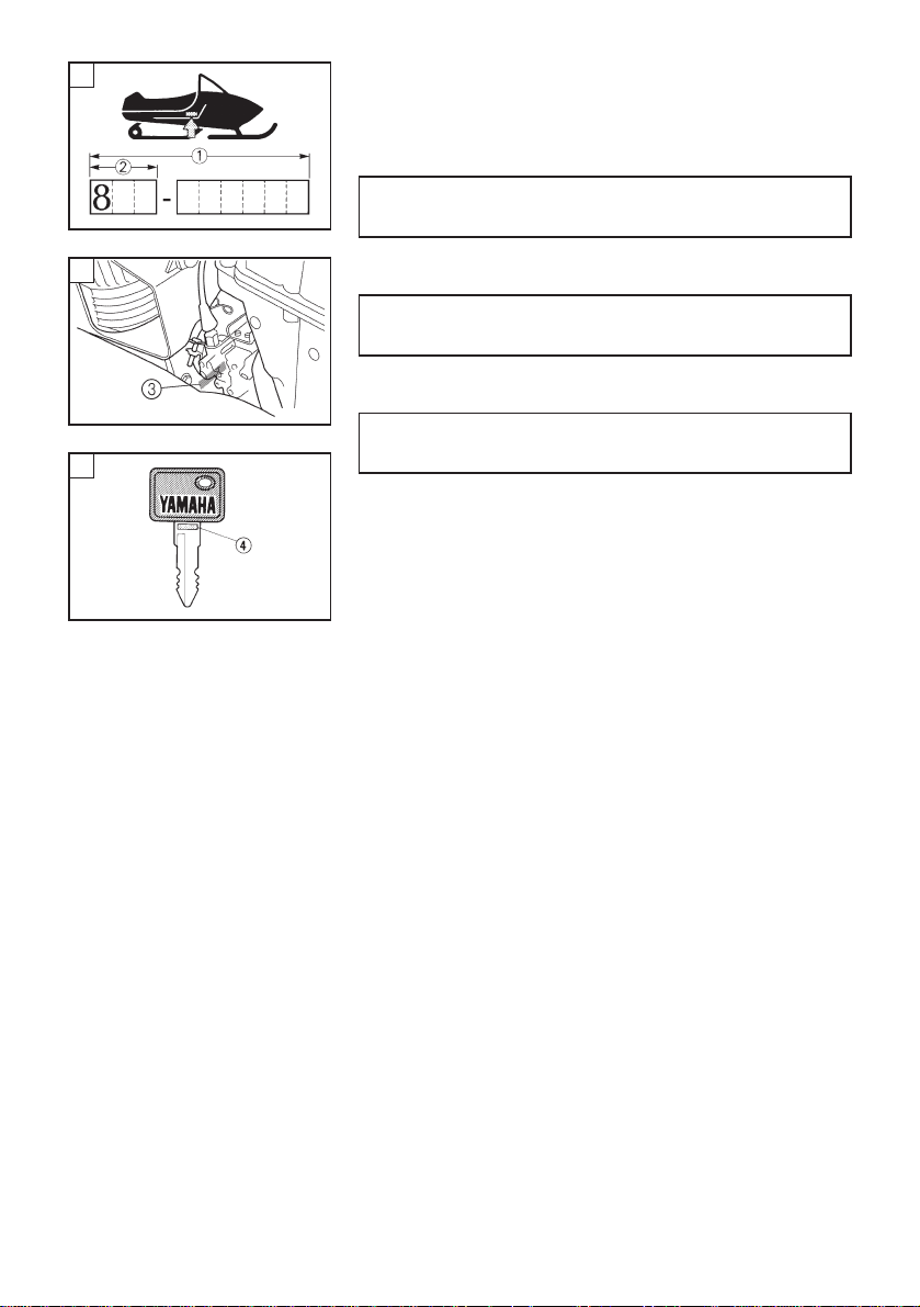
MACHINE IDENTIFICATION
Identification numbers record
A. FRAME NUMBER:
861-001
B
B. ENGINE NUMBER (PRIMARY I.D.):
C. KEY NUMBER:
861-015
C
Record your frame number, engine number (Primary I.D.)
and key number in the spaces provided, to assist you in
ordering spare parts from your Yamaha dealer.
860-002
1 The frame number is the nine-digit number stamped
on the frame of the machine. (See Fig. Å)
2 The model code number is the first three digits of the
frame number. (See Fig. Å)
3 The engine number is stamped in the location as
shown. (See Fig. ı)
4 Key number (See Fig. Ç)
Also, record and keep these I.D. numbers in a separate
place in case your machine is stolen.
Page 3

ESS00000
INTRODUCTION
Congratulations! Your choice of a Yamaha snowmobile
assures you of the highest quality and dependability. Your
Yamaha snowmobile is manufactured by a company wellknown for excellence in the field of snowmobiles. The most
advanced production equipment and technology have
made Yamaha one of the best machine manufacturers.
We are confident that this snowmobile will meet the greatest expectations of our customers. This manual is designed to acquaint you with the operation of this snowmobile and minor maintenance required for satisfactory service.
Should major repairs ever be required, you are advised to
consult a nearby Yamaha dealer who has the techniques,
tools and parts to ensure your satisfaction. We hope that
the information within this booklet will help you enjoy many
hours of pleasure with your Yamaha snowmobile.
PZ500D
PZ500MLD
VT500XLD
OWNER’S MANUAL
©1999 by Yamaha Motor
Corporation, U.S.A.
1st Edition, April 1999
All rights reserved.
Any reprinting or
unauthorized use without
the written permission of
Yamaha Motor Corporation,
U.S.A. is expressly prohibited.
Printed in Japan
P/N LIT-12628-02-08
Page 4
WARNING
PLEASE READ AND UNDERSTAND THIS MANUAL
COMPLETELY BEFORE OPERATING THE MACHINE.
851-005
NOTE:
• Yamaha continually seeks advancements in product
design and quality. Therefore, while this manual contains the most current product information available at
the time of printing, there may be minor discrepancies
between your machine and this manual. If there is any
question concerning this manual, please consult your
Yamaha dealer.
• This manual should be considered a permanent part of
this machine and should remain with this machine when
resold.
Particularly important information is distinguished in this
manual by the following notations.
The Safety Alert Symbol means ATTENTION! BECOME
ALERT! YOUR SAFETY IS INVOLVED!
WARNING
Failure to follow WARNING instructions could result in
severe injury or death to the machine operator, a bystander, or a person inspecting or repairing the machine.
CAUTION
A CAUTION indicates special precautions that must be
taken to avoid damage to the machine.
:
NOTE:
A NOTE provides key information to make procedures
easier or clearer.
Page 5

ESS01300
CONTENTS
YAMAHA MOTOR CORPORATION,
U.S.A. SNOWMOBILE LIMITED
WARRANTY ........................................ 1-1
YAMAHA EXTENDED SERVICE
(Y.E.S.).................................................1-4
LOCATION OF THE IMPORTANT
LABELS............................................... 2-1
SAFETY INFORMATION.....................3-1
DESCRIPTION.....................................4-1
CONTROL FUNCTIONS .....................5-1
MAIN SWITCH...................................5-1
STARTER LEVER (CHOKE) .............5-2
THROTTLE LEVER ...........................5-2
THROTTLE OVERRIDE SYSTEM
(T.O.R.S.) ..........................................5-3
OIL LEVEL WARNING LIGHT........... 5-3
ENGINE STOP SWITCH ...................5-4
BRAKE LEVER.................................. 5-4
PARKING BRAKE LEVER................. 5-5
V-BELT GUARD ................................ 5-5
V-BELT HOLDER .............................. 5-5
SHROUD LATCH ..............................5-6
HEADLIGHT BEAM SWITCH............ 5-6
GRIP WARMER CONTROL KNOB... 5-7
PASSENGER GRIP WARMER
SWITCH (VT500XL) .......................... 5-7
TRIP ODOMETER RESET KNOB..... 5-7
DRIVE SELECT LEVER
(SHIFT LEVER) (VT500XL)............... 5-8
SPARK PLUG HOLDER.................... 5-8
LUGGAGE BOX ................................5-8
BACKREST (VT500XL) .....................5-9
PRE-OPERATION CHECKS ...............6-1
FUEL..................................................6-1
ENGINE OIL ...................................... 6-2
THROTTLE LEVER ...........................6-2
MANUAL STARTER ..........................6-2
THROTTLE OVERRIDE SYSTEM
(T.O.R.S.) CHECK............................. 6-2
BRAKE...............................................6-3
BRAKE FLUID LEAKAGE ................. 6-4
V-BELT .............................................. 6-4
DRIVE V-BELT GUARD .................... 6-4
DRIVE TRACK...................................6-5
38-mm (1.5-in) HIGH-PROFILE PAT-
TERN DRIVE TRACK (PZ500ML)..... 6-5
SLIDE RUNNERS..............................6-6
STEERING SYSTEM.........................6-6
SKI/SKI RUNNER.............................. 6-7
LIGHTS.............................................. 6-7
BATTERY (VT500XL)........................ 6-7
FITTINGS/FASTENERS.................... 6-8
SERVICE TOOLS AND SPARE
PARTS............................................... 6-8
OPERATION........................................ 7-1
STARTING THE ENGINE..................7-1
EMERGENCY ENGINE STARTING.. 7-2
BREAK-IN.......................................... 7-3
RIDING YOUR SNOWMOBILE .........7-4
GETTING TO KNOW YOUR
SNOWMOBILE ..................................7-4
LEARNING TO RIDE YOUR
SNOWMOBILE ..................................7-4
TO START OUT AND
ACCELERATE................................... 7-5
BRAKING...........................................7-5
TURNING ..........................................7-5
RIDING UPHILL.................................7-6
RIDING DOWNHILL .......................... 7-7
CROSSING A SLOPE (SIDE HILL)... 7-7
ICE OR ICY SURFACE ..................... 7-8
HARD-PACKED SNOW .................... 7-8
OPERATION ON SURFACES
OTHER THAN SNOW OR ICE.......... 7-8
STRAP (PZ500ML)............................ 7-9
DRIVING.......................................... 7-10
STOPPING THE ENGINE ............... 7-11
TRANSPORTING ............................ 7-12
Page 6

PERIODIC MAINTENANCE ................ 8-1
MAINTENANCE CHART ................... 8-1
TOOL KIT ..........................................8-4
SPARK PLUG INSPECTION............. 8-4
ENGINE IDLE SPEED
ADJUSTMENT...................................8-5
THROTTLE CABLE ADJUSTMENT.. 8-6
OIL PUMP CABLE ADJUSTMENT.... 8-6
CARBURETOR ADJUSTMENT ........ 8-7
HIGH ALTITUDE ADJUSTMENTS.... 8-9
FAN BELT........................................8-10
DRIVE V-BELT REPLACEMENT .... 8-10
DRIVE CHAIN HOUSING................ 8-13
BRAKE.............................................8-14
BRAKE FLUID REPLACEMENT ..... 8-15
PARKING BRAKE ...........................8-15
SUSPENSION ................................. 8-16
FULL RATE ADJUSTER .................8-18
TRACK ADJUSTMENT ...................8-19
SKI ALIGNMENT .............................8-21
HANDLEBAR ADJUSTMENT
(PZ500/VT500XL)............................ 8-21
HANDLEBAR ADJUSTMENT
(PZ500ML)....................................... 8-22
LUBRICATION.................................8-23
HEADLIGHT .................................... 8-24
BATTERY (VT500XL)...................... 8-25
FUSE REPLACEMENT (VT500XL). 8-26
TROUBLESHOOTING.........................9-1
STORAGE .........................................10-1
RETURN TO SERVICE AFTER
STORAGE ....................................... 10-2
SPECIFICATIONS .............................11-1
DIMENSIONS ..................................11-1
ENGINE ...........................................11-1
CHASSIS .........................................11-2
ELECTRIC .......................................11-3
WIRING DIAGRAM............................12-1
Page 7

ESS79001
YAMAHA MOTOR CORPORATION, U.S.A.
SNOWMOBILE LIMITED WARRANTY
Yamaha Motor Corporation, U.S.A. hereby warrants that
new Yamaha snowmobiles purchased from an authorized Yamaha snowmobile dealer in the continental
United States will be free from defects in material and
workmanship for the period of time stated herein, subject
to certain stated limitations.
WARRANTY PERIOD:
1. All Yamaha snowmobiles shall be warranted for a
term of one (1) year from the date of purchase, plus
a special early-season extension (if applicable).
2. All Yamaha snowmobile clutch components are warranted against abnormal wear for one (1) year from
the date of purchase, plus a special early-season
extension (if applicable).
DURING THE PERIOD OF WARRANTY any au-
thorized Yamaha snowmobile dealer will, free of charge,
repair or replace, at Yamaha’s option, any part adjudged
defective by Yamaha due to faulty workmanship or
material from the factory. Parts used in warranty repairs
will be warranted for the balance of the snowmobile’s
warranty period. All parts replaced under warranty become the property of Yamaha Motor Corporation, U.S.A.
GENERAL EXCLUSIONS from this warranty shall
include any failures to the machine caused by:
1. Competition, racing, or non-Yamaha authorized
rental use.
2. Operation on surfaces other than snow or ice.
3. Installation of parts or accessories that are not qualitatively equivalent to genuine Yamaha parts.
4. Abnormal strain, neglect, or abuse.
5. Lack of proper maintenance.
6. Accident or collision damage.
7. Modification to original parts.
SPECIFIC EXCLUSIONS from this warranty shall
include parts replaced due to normal wear or routine
maintenance including oil, spark plugs, clutch drive belts,
slide runners, and track.
THE CUSTOMER’S RESPONSIBILITY under this
warranty shall be to:
1. Operate and maintain the snowmobile as specified in
the appropriate Owner’s Manual.
2. Give notice to an authorized Yamaha snowmobile
dealer of any and all apparent defects within ten (10)
days after discovery, and make the machine available at that time for inspection and repairs at such
dealer’s place of business. You may locate your
nearest authorized Yamaha dealer through your
local telephone directory.
WARRANTY TRANSFER: To transfer any remain-
ing warranty from the original purchaser to any subsequent purchaser, it is imperative that the machine be
inspected and registered for warranty by an authorized
Yamaha snowmobile dealer. In order for this warranty to
remain in effect, this inspection and registration must
take place within ten (10) days after ownership transfer.
An inspection and registration fee will be charged for this
service.
YAMAHA MOTOR CORPORATION, U.S.A.
MAKES NO OTHER WARRANTY OF ANY
KIND, EXPRESSED OR IMPLIED. ALL IMPLIED WARRANTIES OF MERCHANTABILITY
AND FITNESS FOR A PARTICULAR PURPOSE WHICH EXCEED THE OBLIGATIONS
AND TIME LIMITS STATED IN THIS WARRANTY ARE HEREBY DISCLAIMED BY
YAMAHA MOTOR CORPORATION, U.S.A.
AND EXCLUDED FROM THIS WARRANTY.
SOME STATES DO NOT ALLOW LIMITATIONS
ON HOW LONG AN IMPLIED WARRANTY
LASTS, SO THE ABOVE LIMITATION MAY
NOT APPLY TO YOU. ALSO EXCLUDED
FROM THIS WARRANTY ARE ANY INCIDENTAL OR CONSEQUENTIAL DAMAGES INCLUDING LOSS OF USE. SOME STATES DO
NOT ALLOW THE EXCLUSION OR LIMITATION OF INCIDENTAL OR CONSEQUENTIAL
DAMAGES, SO THE ABOVE EXCLUSION MAY
NOT APPLY TO YOU.
THIS WARRANTY GIVES YOU SPECIFIC LEGAL RIGHTS, AND YOU MAY ALSO HAVE
OTHER RIGHTS WHICH VARY FROM STATE
TO STATE.
1-1
Page 8

SPECIAL EARLY-SEASON WARRANTY EXTENSION
A special warranty extension is available for all new
Yamaha snowmobiles purchased between June 1 and
December 1.
All new Yamaha snowmobiles purchased between June
1 and December 1 will have the warranty extended to
November 30 of the following year.
YAMAHA MOTOR CORPORATION, U.S.A.
Post Office Box 6555
Cypress, California 90630
WARRANTY QUESTIONS AND
ANSWERS
Q. Will the warranty be void or cancelled if I do not
operate or maintain my new Yamaha exactly as
specified in the Owner’s Manual?
A. No. The warranty on a new Yamaha cannot be
“voided” or “cancelled.” However, if a particular failure is caused by operation or maintenance other than
as shown in the Owner’s Manual, that failure may not
be covered under warranty.
Q. What responsibility does my dealer have under this
warranty?
A. Each Yamaha snowmobile dealer is expected to:
1. Completely set up every new machine before sale.
2. Explain the operation, maintenance, and warranty
requirements to your satisfaction at the time of sale,
and upon your request at any later date.
3. In addition, each Yamaha snowmobile dealer is held
responsible for his setup, service and warranty repair
work.
Q. What costs are my responsibility during the warranty
period?
A. The customer’s responsibility includes all costs of
normal maintenance services, non-warranty repairs,
accident and collision damages, as well as oil, spark
plugs, clutch drive belts, and slide runners.
Q. What are some examples of “abnormal” strain, ne-
glect, or abuse?
A. These terms are general and overlap each other in
areas. Specific examples include: Running the machine out of oil, hitting an object submerged under
snow, operation on surfaces other than snow or ice,
operating the machine with a broken or damaged
part which causes another part to fail, and so on. If
you have any specific questions on operation or
maintenence, please contact your dealer for advice.
Q. May I perform any or all of the recommended main-
tenance shown in the Owner’s Manual instead of
having the dealer do them?
A. Yes, if you are a qualified snowmobile mechanic and
follow the procedures specified in the Owner’s and
Service Manual. We do recommend, however, that
items requiring special tools or equipment be done by
a Yamaha snowmobile dealer.
Q. Under what conditions is the clutch not covered by
warranty?
A. Clutches as well as clutch components wear with
use. Normal wear is not covered under warranty such
service is the customer’s responsibility. Abnormal
wear is, however, covered for one (1) year from the
date of purchase. Your Yamaha snowmobile dealer
possesses criteria as to what constitutes abnormal
wear.
Q. Whom should I contact if I have further questions
about this warranty?
A. Your Yamaha snowmobile dealer has the informa-
tion and experience necessary to answer almost any
questions about this warranty. If the dealer is not able
to do so, he is expected to contact Yamaha Motor
Corporation, U.S.A., for clarification or assistance.
CUSTOMER SERVICE
If your machine requires warranty service, you must take
it to any authorized Yamaha snowmobile dealer within
the continental United States. Be sure to bring your
warranty identification card or other valid proof of the
original date of purchase. If a question or problem arises
regarding warranty, first contact the owner of the dealership. Since all warranty matters are handled at the dealer
level, this person is in the best position to help you. If you
are still not satisfied and require additional assistance,
please write:
YAMAHA MOTOR CORPORATION
U.S.A.
CUSTOMER RELATIONS DEPART-
MENT
P.O. Box 6555
Cypress, California 90630
1-2
Page 9

When contacting Yamaha Motor Corporation, U.S.A. be sure to include the model,
serial number, names, dates, and receipts.
CHANGE OF ADDRESS
The federal government requires each manufacturer of a
motor vehicle to maintain a complete, up-to-date list of all
first purchasers against the possibility of a safety-related
defect and recall. This list is compiled from the purchase
registrations sent to Yamaha Motor Corporation, U.S.A.
by the selling dealer at the time of your purchase.
If you should move after you have purchased your new
snowmobile, please advise us of your new address by
sending a postcard listing your snowmobile model name,
engine serial number, dealer number (or dealer’s name)
as it is shown on your warranty registration identification,
your name and new mailing address. Mail to:
YAMAHA MOTOR CORPORATION,
U.S.A.
WARRANTY DEPARTMENT
P.O. Box 6555
Cypress, California 90630
This will ensure that Yamaha Motor Corporation, U.S.A.
has an up-to-date registration record in accordance with
federal law.
1-3
Page 10

ESS79500
YAMAHA EXTENDED SERVICE (Y.E.S.)
Keep your Yamaha protected even after your
warranty expires with genuine Yamaha Extended Service (Y.E.S.).
• Y.E.S. is designed and administered by
Yamaha Motor Corporation to provide
maximum owner satisfaction. You get uninterrupted factory-backed coverage for
extra peace of mind.
• Y.E.S. is flexible. You choose the plan that’s
right for you: 12 months, 24 months, or 36
months beyond your warranty period.
• Y.E.S. is designed and administered by the
same Yamaha people who handle your
warranty — and it shows in the comprehensive coverage benefits. There are no
mileage limitations. Coverage isn’t limited
to “moving parts” or the “drive train” like
many other plans. And Y.E.S. covers manufacturing defects just like the warranty. See
the sample contract at your Yamaha dealer
to see how comforting uninterrupted factory-backed protection can be.
• You don’t have to pay anything for covered
repairs.
There’s no deductible to pay, and repairs
aren’t “pro-rated.” You don’t have any
“out-of pocket” expenses for covered repairs.
• In addition, Travel and Recreation Inter-
ruption Protection (TRIP) is included at no
extra cost. TRIP gives you up to $150 reimbursement per occurrence for any reasonable expenses you incur because your
Yamaha needs covered service: replacement vehicle rental, emergency towing,
phone calls, even food and lodging when
you are away from home. This superb
coverage goes into effect when you purchase Y.E.S., so it applies to any warranty
repairs as well as covered repairs during
your entire Y.E.S. plan period.
• Y.E.S. coverage is honored at any author-
ized Yamaha dealer nationwide.
• Y.E.S. coverage is transferrable to a new
owner if you sell or trade-in. That can make
your Yamaha much more valuable!
This excellent Y.E.S. plan coverage is only
available to Yamaha owners like you, and only
while your Yamaha is still within the Yamaha
Limited Warranty period. So visit your authorized Yamaha dealer to get all the facts. He can
show you how easy it is to protect your investment with Yamaha Extended Service.
We urge you to act now. You’ll get the excellent benefits of TRIP coverage right away, and
you’ll rest easy knowing you’ll have strong
factory-backed protection even after your
Yamaha Limited Warranty expires. You can
also save money: Y.E.S. costs less within the
first 90 days after you buy your Yamaha. See
your dealer today!
A special note:
If visiting your dealer isn’t convenient, contact
Yamaha with your Primary ID number (your
engine number). We’ll be happy to help you
get the Y.E.S. coverage you need.
Yamaha Service Marketing P.O.Box 6555
Cypress, CA 90630
(714) 761-7631
1-4
Page 11
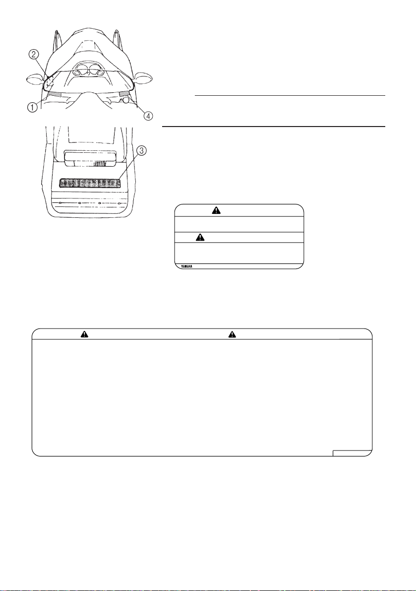
ESB01500
LOCATION OF THE
IMPORTANT LABELS
Please read the following labels carefully before operating
this machine.
NOTE:
Maintain or replace safety and instruction labels, as necessary.
2
DO NOT OPERATE ENGINE WITHOUT
V-BELT OR DRIVE GUARD.
NE PAS FAIRE FONCTIONNER LE
MOTEUR SANS COURROIE EN V
OU PROTECTEUR D’EMBRAYAGE.
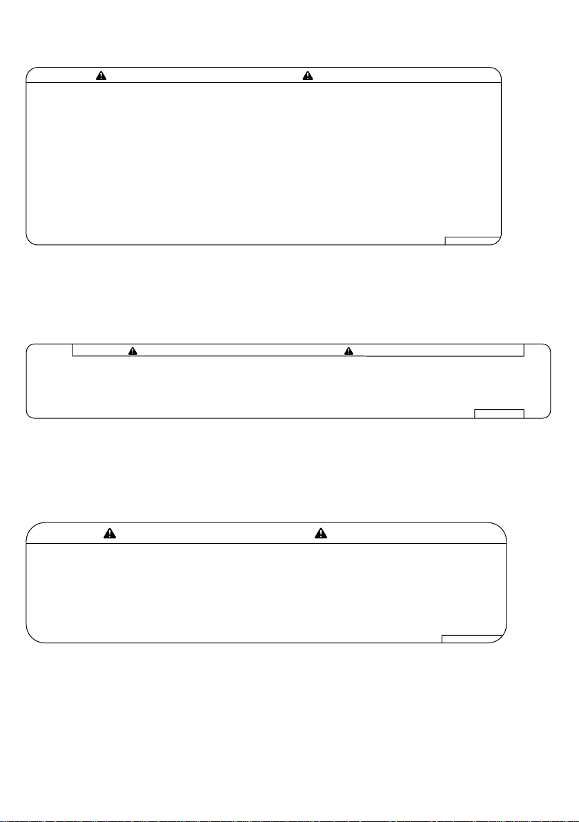
1 PZ500/PZ500ML
SEVERE INJURY OR DEATH MAY RESULT IF YOU IGNORE ANY OF
THE FOLLOWING:
•
Read the Owner’s Manual and all labels before operating this vehicle.
• This vehicle is a high performance machine.
It should be operated by an experienced operator.
•
Check throttle, brake, and steering for proper operation before starting engine.
• Set parking brake before attempting to start engine.
Never run this vehicle with the parking brake applied.
•
To stop engine in an emergency, push the engine stop switch down.
• Do not operate engine without drive belt or drive guard.
• Make sure the fuel tank cap is closed securely after refueling.
• Do not operate this vehicle on public roads.
You could collide with another vehicle.
• This vehicle is designed for operator only - no passengers.
•
Wear an approved helmet, eye protection, and adequate clothing for
snowmobiling.
WARNING
WARNING
AVERTISSEMENT
8BD-77762-00
AVERTISSEMENT
AFIN D’ÉVITER TOUT RISQUE DE BLESSURE SÉRIEUSE OU MÊME MORTELLE,
VEUILLEZ SUIVRE LES RECOMMANDATIONS SUIVANTES:
•
Avant d’utiliser ce véhicule, lire le manuel du propriétaire et toutes les étiquettes.
• Ce véhicule est une machine à haute perfomance.
Elle doit être conduite par un conducteur expérimenté.
•
Avant de démarrer le moteur, vérifier l’opération du frein, de l’accélérateur
et de la direction.
•
Le frein de sécurité doit être appliqué lors du démarrage.
Ne pas rouler avec le frein de sécurité actionné.
•
En cas d’urgence, utiliser l’interrupteur d’arrêt du moteur.
•
Ne pas laisser tourner le moteur sans la courroie ou sans son garde.
• S’assurer que le bouchon du réservoir soit bien refermé après le remplissage.
•
Afin d’éviter tout risque de collision, ne pas rouler sur un chemin public.
• Ce véhicule est conçu pour un conducteur seul - aucun passager.
•
Toujours porter un casque approuvé et un habillement de motoneigiste.
Prévoir une protection pour les yeux.
8DS-77761-00
2-1
Page 12
1 VT500XL
SEVERE INJURY OR DEATH MAY RESULT IF YOU IGNORE ANY OF
THE FOLLOWING:
•
Read the Owner’s Manual and all labels before operating this vehicle.
• This vehicle is a high performance machine.
It should be operated by an experienced operator.
Check throttle, brake, and steering for proper operation before starting engine.
•
• Set parking brake before attempting to start engine.
Never run this vehicle with the parking brake applied.
To stop engine in an emergency, push the engine stop switch down.
•
• Do not operate engine without drive belt or drive guard.
• Make sure the fuel tank cap is closed securely after refueling.
• Do not operate this vehicle on public roads.
You could collide with another vehicle.
Wear an approved helmet, eye protection, and adequate clothing for
•
snowmobiling.
• Check lever position (Forward or Reverse) before moving.
AFIN D’ÉVITER TOUT RISQUE DE BLESSURE SÉRIEUSE OU MÊME MORTELLE,
VEUILLEZ SUIVRE LES RECOMMANDATIONS SUIVANTES:
•
Avant d’utiliser ce véhicule, lire le manuel du propriétaire et toutes les étiquettes.
• Ce véhicule est une machine à haute perfomance.
Elle doit être conduite par un conducteur expérimenté.
• Avant de démarrer le moteur, vérifier l’opération du frein, de l’accélérateur
et de la direction.
• Le frein de sécurité doit être appliqué lors du démarrage.
Ne pas rouler avec le frein de sécurité actionné.
• En cas d’urgence, utiliser l’interrupteur d’arrêt du moteur.
• Ne pas laisser tourner le moteur sans la courroie ou sans son garde.
• S’assurer que le bouchon du réservoir soit bien refermé après le remplissage.
Afin d’éviter tout risque de collision, ne pas rouler sur un chemin public.
•
• Toujours porter un casque approuvé et un habillement de motoneigiste.
Prévoir une protection pour les yeux.
Vérifier la position du levier (marche avant ou arrière) avant d’être en marche.
•
3 PZ500ML/VT500XL
WARNING
NO PASSENGER OR CARGO ON THIS TRACK COVER.
If was not designed to carry weight. It could bend or break under
load.
Anything placed here could block the view of the break/tail light
which could cause an accident.
WARNING
AVERTISSEMENT
8DM-77761-00
AUCUN PASSAGER OU MARCHANDISE SUR LE PROTECTEUR DE
CHENILLE.
Ce protecteur n’a pas été conçu pour supporter un poids. Il pourrait
s’incurver ou se briser sous la charge.
Tout objet ou personne placé à cet endroit pourrait bloquer la vue
des feux d’arrêt/amére et ainsi causer un accident.
AVERTISSEMENT
8CY-77762-00
4 PZ500ML
WARNING
Improper use of STRAP on the handlebar can result in
SEVERE INJURY or DEATH.
• Use strap only as an operator grip point to shift weight
uphill to maintain balance during traverse ( sidehill ) riding.
• Keep one hand on handlebar. Do not change speed or
direction abruptly.
• Only experienced operators should traverse slopes steep
enough to require strap use.
AVERTISSEMENT
L’utilisation incorrecte de la POIGNÉE SOUPLE du guidon peut
causer des BLESSURES GRAVES voire MORTELLES.
• S’agripper à la poignée seulement lors de la traversée latérale
de pentes pour garder l’équilibre lorsque l’on déplace son poids
du côté amont.
• Garder une main sur le guidon. Éviter toute accélération ou
freinage brusques.
• La traversée de pentes dont la raideur requiert l’utilisation de la
poignée est réservée aux pilotes expérimentés.
2-2
8ED-77761-00
Page 13
851-005
851-004
ESS39203
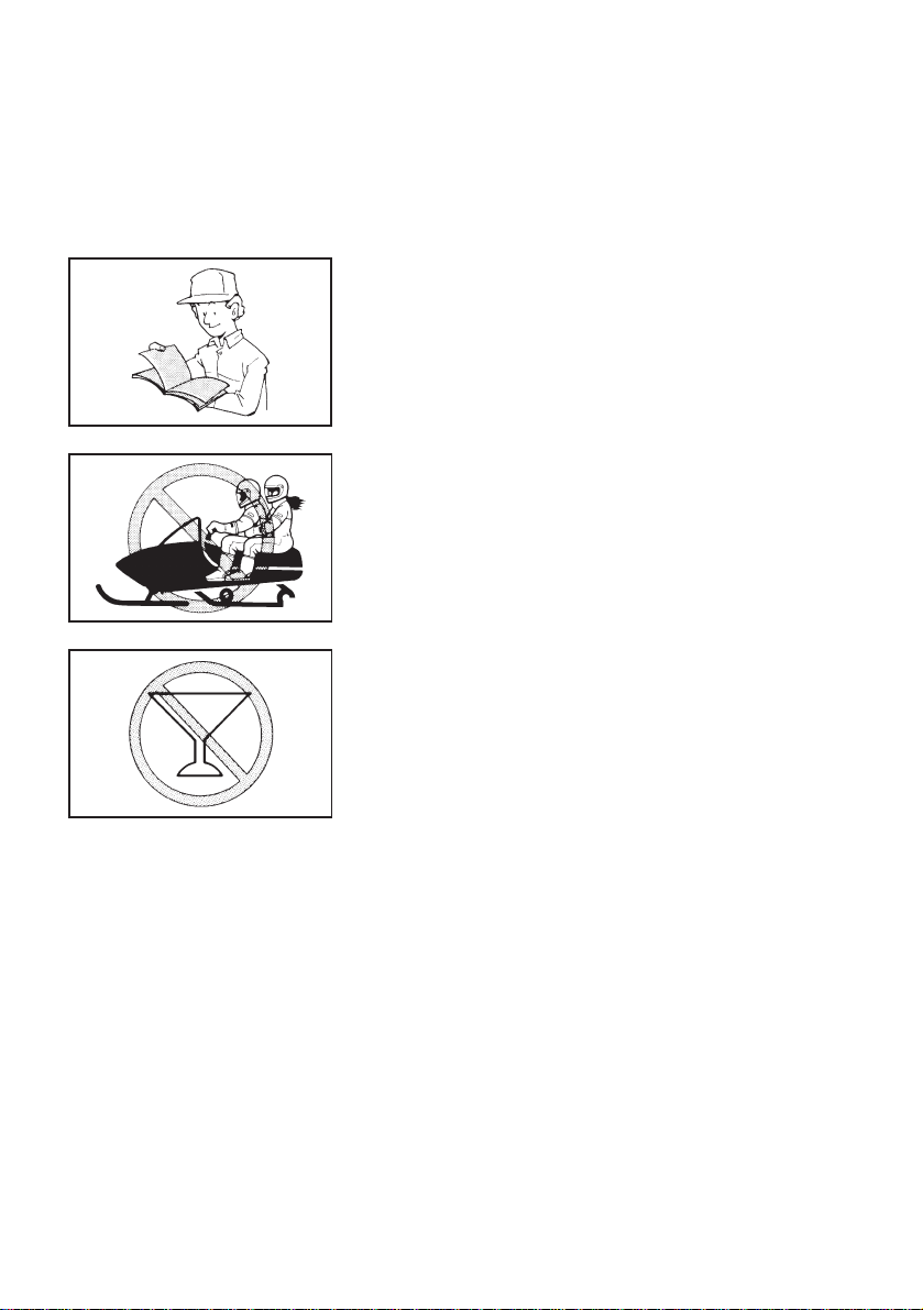
SAFETY INFORMATION
When you ride your snowmobile, you must know and use
the following for your safety. Severe injury or death may
result if you ignore any of the following.
Before Operating
1. Read the Owner’s Manual and all labels before operating this machine. Become familiar with all of the operating controls and their function. Consult a Yamaha
dealer about any control or function you do not understand.
2. This machine was not manufactured for use on public
streets, roads, or highways. Such use is prohibited by
law, and you could collide with another vehicle.
3. PZ500 and PZ500ML are designed to carry the OPERATOR ONLY.
Passengers are prohibited. Carrying a passenger can
cause loss of control.
851-006
4. Do not operate the machine after drinking alcohol or
taking drugs. Your ability to operate the machine is
reduced by the influence of alcohol or drugs.
5. For safety and proper care of the machine, always
perform the pre-operation checks on pages 6-1 ~
6-8 before starting the engine. Check the throttle,
steering and brake operation every time before starting
the engine. Be sure the throttle lever moves freely and
it returns to the idle position when it is released.
6. Apply the parking brake before starting the engine.
Never drive the machine with the parking brake applied. This may overheat the brake disc and reduce
braking ability.
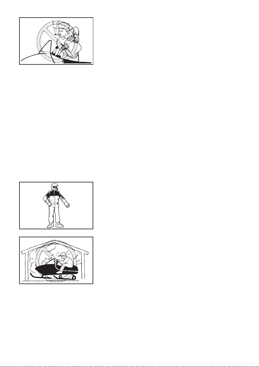
7. Do not allow anyone to stand behind the machine when
starting, inspecting or adjusting the machine. A broken
track, track fittings or debris thrown by the track could
be dangerous to the operator or bystanders.
3-1
Page 14
851-003
8. Handle fuel with care; it is highly flammable.
• Never add fuel when the engine is running or hot.
Allow the engine to cool for several minutes after
running.
• Use an approved fuel container.
• Fill the fuel tank outdoors with extreme care. Never
remove the fuel cap indoors. Never fill the fuel tank
indoors.
• Never refuel while smoking or in the vicinity of an
open flame.
• Make sure the fuel tank cap is closed securely after
refueling. Wipe up any spilled fuel immediately.
9. If you swallow some gasoline, inhale a lot of gasoline
vapor, or get some gasoline into your eye(s), see your
doctor immediately. If any gasoline spills on your skin
or clothing, immediately wash your skin with soap and
water, and change your clothes.
10.Wear protective clothing. Wear an approved helmet,
and a face shield or goggles. Also, wear a good quality
snowmobile suit, boots, and a pair of snowmobile
gloves or mittens that will permit use of your thumbs
and fingers for operation of the controls.
851-001
851-002
Operation
1. Do not run the engine indoors, except when starting the
engine to transport the machine in or out of the building.
Open the outside doors; exhaust fumes are dangerous.
2. Be careful where you ride. There may be obstacles
hidden beneath the snow. Stay on established trails to
minimize your exposure to hazards. Ride slowly and
cautiously when you ride off of established trails. Hitting
a rock or stump, or running into wires could cause an
accident and injury.
3-2
Page 15

3. This machine is not designed for use on surfaces other
than snow or ice. Use on dirt, sand, grass, rocks, or bare
pavement may cause loss of control and may damage
the machine.
4. Avoid operating on glare ice, or on snow which has a lot
of dirt or sand mixed in. Operation under such conditions will damage or result in rapid wear of ski runners,
drive track, slide runners and drive sprockets.
5. Always have other snowmobilers with you when going
on a ride. You may need help if you run out of fuel, have
an accident, or damage your snowmobile.
6. Many surfaces such as ice and hard-packed snow
require much longer stopping distances. Be alert, plan
ahead and begin decelerating early. The best braking
method on most surfaces is to release the throttle and
apply the brake gently – not suddenly.
Maintenance and Storage
1. Do not leave the machine on its left side for an extended
period of time. Fuel may leak out from the fuel breather
hose.
2. Modifications made to the machine not approved by
Yamaha, or the removal of original equipment may
render your machine unsafe for use and may cause
severe personal injury. Modifications may also make
your machine illegal to use.
3. Never store the machine with fuel in the fuel tank inside
a building where ignition sources are present such as
hot water and space heaters, open flame, spark, clothes
dryers, and the like. Allow the engine to cool before
storing in any enclosure.
4. Always refer to “STORAGE” for important details if the
machine is to be stored for an extended period.
5. Maintain or replace safety and instruction labels, as
necessary.
3-3
Page 16

–MEMO–
Page 17
PZ500
PZ500ML
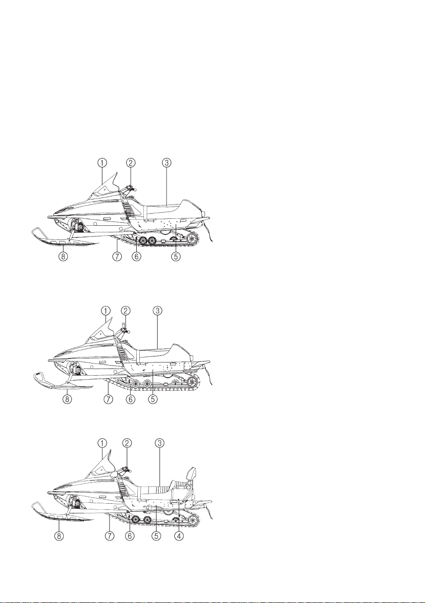
ESG05100
DESCRIPTION
1 Windshield
2 Steering handlebar
3 Seat
4 Passenger grip warmer switch
(VT500XL)
5 Frame
6 Slide rail suspension
7 Drive track
8 Steering ski
VT500XL
4-1
Page 18
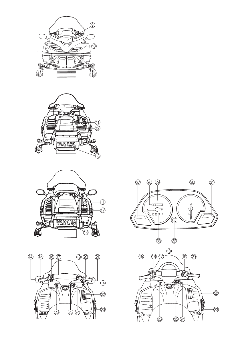
VT500XL
9 Headlight
0 Shroud
A Luggage box
B Taillight
C Flap
D Side mirror (VT500XL)
E Brake lever
F Headlight beam switch
G Parking brake lever
H Strap (PZ500ML)
I Engine stop switch
J Throttle lever
K Drive select lever (VT500XL)
L Starter handle
M Shroud latch
N Main switch
O Starter lever
P Grip warmer control knob
Q “HIGH BEAM” indicator light
R Odometer
S Speedometer
T Tachometer
U “OIL LEVEL” warning indicator light
V Trip odometer reset knob
W Trip odometer
PZ500ML
4-2
Page 19
AB
831-027
ESG05000
CONTROL FUNCTIONS
ESS08802
MAIN SWITCH
The main switch controls the following items.
1 OFF:
The ignition circuit is switched off.
The key can be removed only in this position.
2 ON:
The ignition circuit is switched on.
The engine can be started.
3 WARMER:
The grip and thumb warmer circuit is switched on.
Also, the ignition circuit is switched on and the engine can
be started.
NOTE:
The handlebar grips and throttle lever will heat electrically
after the engine starts.
4 START (VT500XL):
The starting circuit is switched on.
The starter motor starts.
NOTE:
The lights will come on after the engine starts.
CAUTION
:
Release the switch immediately after the engine starts.
Å PZ500/PZ500ML
ı VT500XL
5-1
Page 20
815-001
816-001
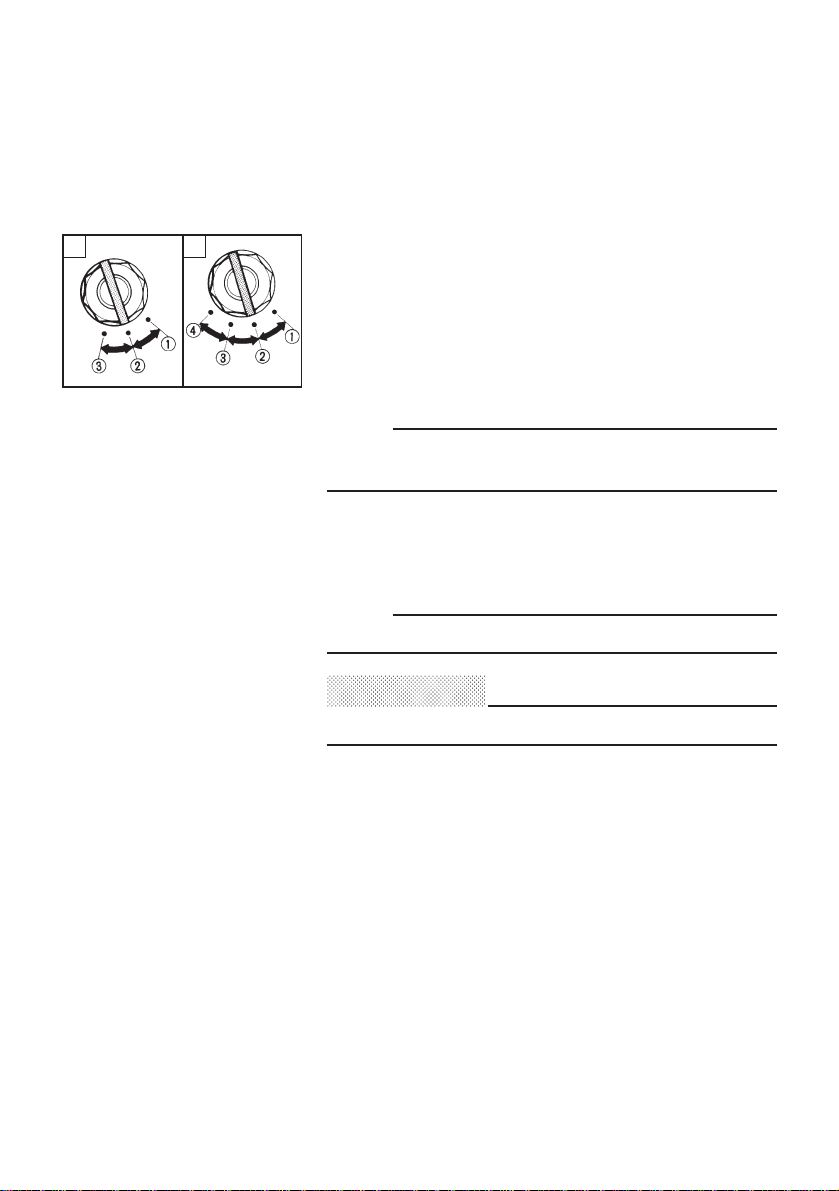
ESS22200
STARTER LEVER (CHOKE)
Use this lever when starting and warming up a cold engine.
1 Starter lever (choke)
2 When starting a cold engine.
3 Warming up
4 When the engine is warm.
NOTE:
Refer to STARTING THE ENGINE for proper operation.
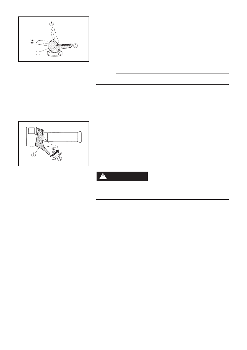
ESS21600
THROTTLE LEVER
Once the engine is running cleanly, squeezing 2 the throttle
lever 1 will increase the engine speed and cause engagement of the drive system. Regulate the speed of the machine
by varying the throttle position. Because the throttle is
spring-loaded, the machine will decelerate, and the engine
will return to an idle when the thumb is released 3.
WARNING
Check the throttle, brake, and steering for proper
operation before starting engine.
5-2
Page 21
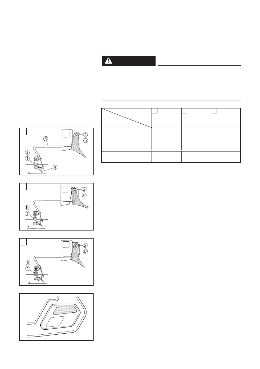
ESS22301
THROTTLE OVERRIDE SYSTEM (T.O.R.S.)
If the carburetor or throttle cable should malfunction during
operation, release the throttle lever. The T.O.R.S. is designed to interrupt the ignition and stop the engine if the
carburetor fails to return to idle when the lever is released.
WARNING
If T.O.R.S. stops the engine, make sure that the cause
of the malfunction has been corrected and that the
engine can be operated without a problem before
restarting the engine.
A B C
MODE
SWITCH
A
Throttle switch
Idle
or
starting
OFF
Run Trouble
ON
OFF
816-003
Carburetor switch
Engine
Å Idle or starting
ON
RUN
OFF
RUN
OFF
STOP
ı Run
B
Ç Trouble
1 Carburetor switch
2 Throttle switch
3 Throttle cable
4 Throttle valve
816-004
a “ON”
b “OFF”
C
816-005
ESS21900
OIL LEVEL WARNING LIGHT
If the oil level falls below the lower level, this light comes on.
If the light comes on, add engine oil to the oil tank at the first
opportunity.
833-010
5-3
Page 22
831-008
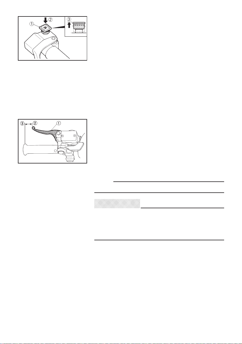
ESS20800
ENGINE STOP SWITCH
The engine stop switch 1 is used to stall the engine in an
emergency. Simply push 2 the engine stop switch, and
the engine will stop. To start the engine, pull 3 the engine
stop switch and see page 7-1 for more details. During the
first few rides, you should practice using the switch while
driving so that you can react quickly in an emergency.
ESS28100
BRAKE LEVER
The machine is stopped by braking the entire drive system.
Squeeze the brake lever towards the handlebar to stop the
machine.
818-035
1 Brake lever
2 Brake lever end
3 Handlebar end
NOTE:
When the brake is operated, the brake light will illuminate.
CAUTION
Be sure the brake lever end does not project out over
the handlebar end. This will help prevent brake lever
damage when the machine is placed on its side for
service.
:
5-4
Page 23
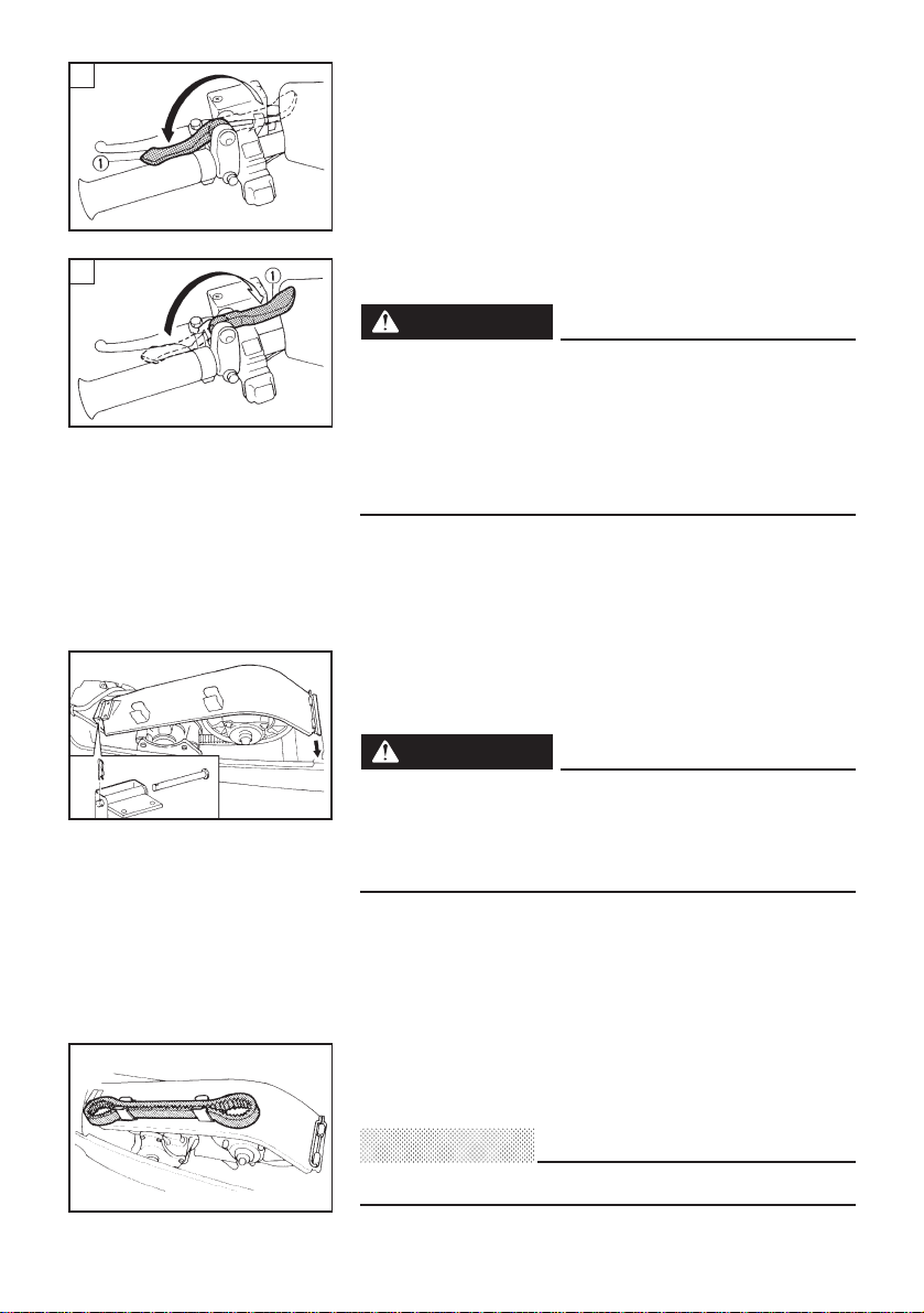
ESS27100
A
PARKING BRAKE LEVER
When parking the machine or starting the engine, apply the
parking brake by moving the parking brake lever 1 to the
left.
To release the parking brake, move the parking brake
818-036
lever 1 to the right.
B
Å To apply the parking brake
ı To release the parking brake
WARNING
• Always set the parking brake before attempting to
start the engine.
818-037
• Never run the machine with the parking brake ap-
plied.
This may overheat the brake disc and reduce braking ability.
ESS28700
V-BELT GUARD
The V-belt guard is designed to cover the clutch and V-belt
in case parts break or come loose.
WARNING
845-062
• Be sure the V-belt guard is tightened securely
before operating the machine.
• Never run the engine without the V-belt or with the
V-belt guard removed.
845-061
ESS08100
V-BELT HOLDER
Keep a spare V-belt for emergency use by putting it into the
holder provided.
CAUTION
:
Be sure the V-belt is installed securely in the holder.
5-5
Page 24
ESS29100
SHROUD LATCH
To open the shroud, unhook the latch, then slowly raise the
shroud forward until it stops. When closing the shroud,
slowly lower it to its home position, then hook the shroud
latches.
845-023
831-045
1 Latch
2 Shroud
CAUTION
:
Be sure all cables and wires are in place when closing
the shroud.
WARNING
• Do not drive the machine with the shroud open or
unlatched or with the shroud removed.
• Keep your body and clothing away from rotating
parts when servicing with the shroud open.
• Do not touch the hot muffler and engine during or
immediately after operation.
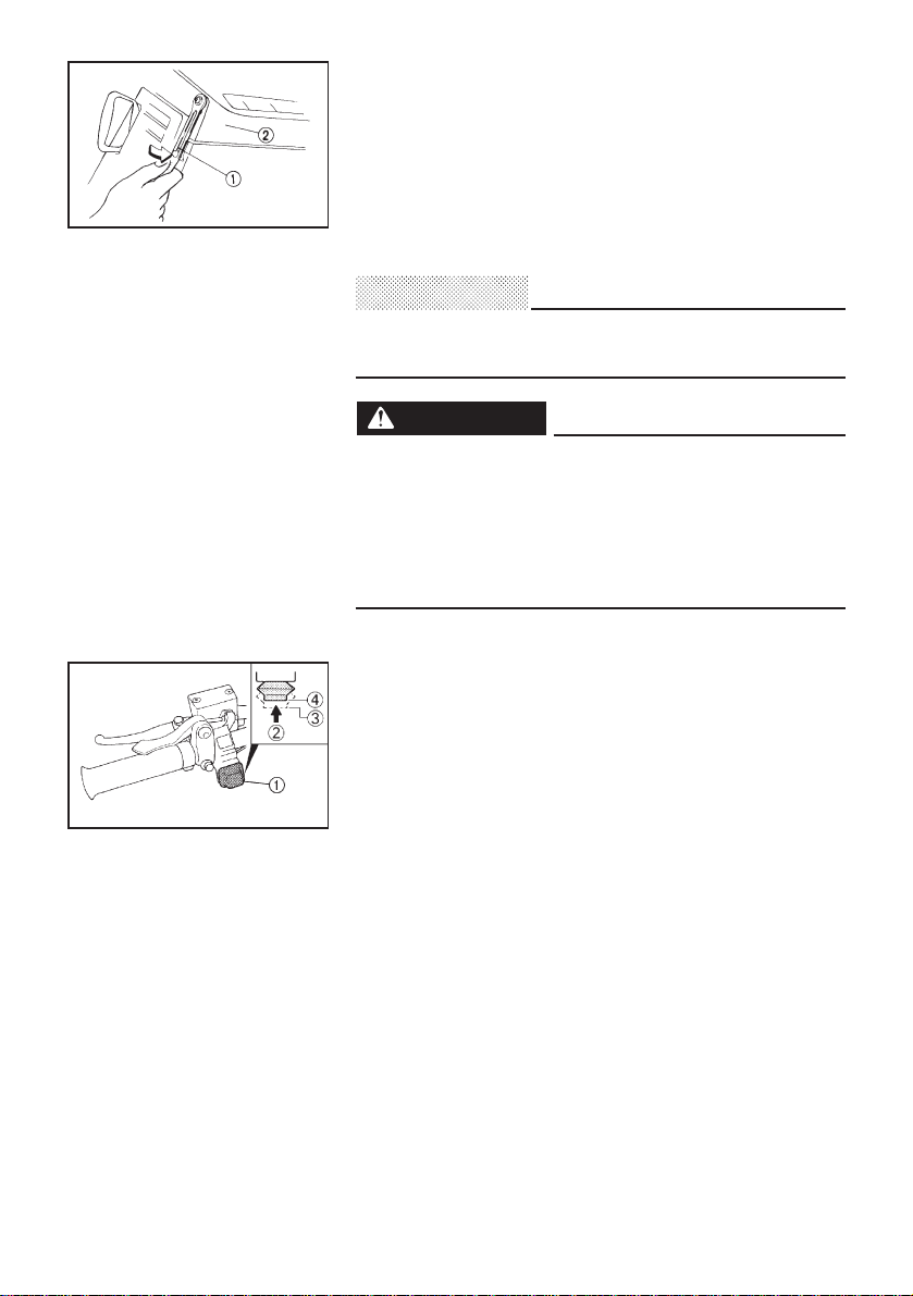
ESS28300
HEADLIGHT BEAM SWITCH
Push the switch to change the head light beam alternately
to high or low.
1 Headlight beam switch
2 Push
3 High beam
4 Low beam
5-6
Page 25
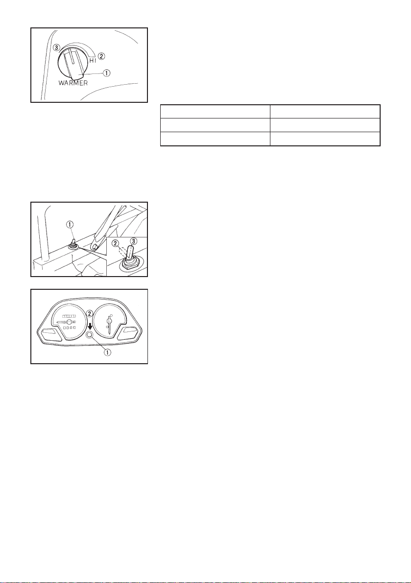
ESS09000
GRIP WARMER CONTROL KNOB
This knob controls the electrically heated handlebar grips
and throttle lever when the main switch is in the “WARMER”
position.
831-039
831-036
833-019
1 Grip warmer control knob
Knob position Warmer temperature
2 Turn clockwise Higher
3 Turn counterclockwise Lower
ESS08900
PASSENGER GRIP WARMER SWITCH (VT500XL)
This switch controls the electrically heated passenger
grips.
1 Passenger grip warmer switch
2 ON
3 OFF
ESS29900
TRIP ODOMETER RESET KNOB
Use the knob to reset the trip odometer.
1 Reset knob
2 Push
5-7
Page 26

ESS23701
DRIVE SELECT LEVER (SHIFT LEVER) (VT500XL)
The drive select lever is used to shift your machine into
forward or reverse. After coming to a complete stop, move
the lever to the desired direction.
817-006
817-007
834-043
AB
1 Drive select lever (shift lever)
2 Push down
3 Move to forward
4 Move to reverse
Machine movement
FWD Forward
REV Reverse
CAUTION
:
Do not shift from “Forward” to “Reverse” or “Reverse”
to “Forward” while the machine is moving. Otherwise
the drive system could be damaged.
ESS28401
SPARK PLUG HOLDER
Keep spare spark plugs for emergency use by placing
them into the holder provided.
ESS24200
LUGGAGE BOX
Open the box to store the service tools, spare parts, or
other small items.
846-034
Å PZ500/PZ500ML
ı VT500XL
5-8
Page 27

849-002
849-003
ESS09500
BACKREST (VT500XL)
This backrest is adjustable.
Remove the mount bolts 1 and adjust the backrest position.
WARNING
Make sure that the mount bolts are tightened securely
after adjusting.
Backrest position:
2 Front position 1
3 Front position 2
4 Rear position 1
5 Rear position 2
6 Rear position 3
7 Rear position 4
5-9
Page 28

801-022
ESB30000
PRE-OPERATION CHECKS
NOTE:
Pre-operation checks should be made each time the
machine is used.
WARNING
The engine and muffler will be very hot after the engine
has been run.
Avoid touching the engine and muffler while they are
still hot with any part of your body or clothing during
inspection or repair.
ESS30303
FUEL
Make sure that there is sufficient fuel in the tank.
Recommended fuel:
Unleaded gasoline
Pump octane
Fuel tank capacity:
Total: 44.3 L (9.7 Imp gal, 11.7 US gal)
R+M
2
; 88 or higher
801-023
801-024
801-025
WARNING
• Fuel is highly flammable and poisonous. Check
“SAFETY INFORMATION” (see page 3-2) carefully
before refueling.
• Do not fill the fuel tank above the bottom of the filler
tube 1. The fuel could overflow if the machine is
tilted or if the ambient temperature rises, causing
the fuel to warm up and expand.
• Make sure that the fuel tank cap is closed securely
after refueling. Leaking fuel can catch fire.
2 Fuel level
CAUTION
:
• Oxygenated fuels (“gasohol”) containing max. 5%
of ethanol can be used, although richer jetting may
be required to prevent engine damage. Consult a
Yamaha dealer. Gasohol containing methanol is
not recommended.
6-1
Page 29

800-032
816-037
• Be sure that snow and /or ice does not enter into the
fuel tank when refueling.
• Do not use alcohol deicers or water absorbing
additives with oxygenated fuel.
• The tank should be filled with straight gasoline as
specified.
ESS33100
ENGINE OIL
Make sure that there is sufficient oil in the oil tank.
Oil tank capacity: 3.3 L (2.9 Imp qt, 3.5 US qt)
Recommended oil: YAMALUBE 2-cycle oil
ESS31500
THROTTLE LEVER
Check the throttle lever operation before starting the engine.
It must open smoothly and spring back to idle when
released.
ESS31200
MANUAL STARTER
Check for proper operation. Check the rope for damage.
815-005
818-044
ESS31301
THROTTLE OVERRIDE SYSTEM (T.O.R.S.) CHECK
WARNING
When checking T.O.R.S.:
• Be sure the parking brake is applied.
• Be sure the throttle lever moves smoothly.
• Do not run the engine up to clutch engagement
r/min. Otherwise, the machine could start moving
forward unexpectedly, which could cause an accident.
1. Start the engine.
NOTE:
Refer to STARTING THE ENGINE.
6-2
Page 30

2
3
1
816-040
2. Hold the pivot point of the throttle lever away from the
throttle switch by putting your thumb (above) and forefinger (below) between the throttle lever pivot 1 and
stop switch housing 2.
While holding as described above, press the throttle
lever 3 gradually.
The engine should stop immediately.
WARNING
If the engine does not stop, stop the engine by turning
the main switch to the “OFF” position and consult a
Yamaha dealer.
ESS37000
BRAKE
(See page 8-14 ~ 8-15 for more details.)
1. Brake lever
Test the brake at slow speed when starting out to make
sure it is working properly. If the brake does not provide
proper braking performance, inspect the brake for wear
or brake fluid leakage.
WARNING
A soft, spongy feeling in the brake lever indicates a
failure in the brake system.
Do not operate the machine if you find any problems in
the brake system. Consult a Yamaha dealer for immediate repairs. You could lose braking ability, which
could lead to an accident.
818-038
CAUTION
Make sure that the brake lever end does not project out
over the handlebar end. This is to prevent brake lever
damage when the machine is placed on its side.
2. Brake fluid
Check the brake fluid level.
Add fluid if necessary.
1 Lower level
(See page 8-14.)
Recommended brake fluid: DOT 4
:
6-3
Page 31

ESS37100
BRAKE FLUID LEAKAGE
Apply the brake for a few minutes. Check to see if any brake
fluid leaks out from the pipe joints or the master cylinder.
WARNING
If brake fluid leakage is found, consult a Yamaha
dealer for immediate repairs.
805-106
CAUTION
:
Brake fluid may deteriorate painted surfaces or plastic
parts. Never spill any fluid. If any is spilled, clean it up
immediately.
ESS31800
V-BELT
Open the shroud and remove the V-belt guard.
Check the V-belt for wear and damage. Replace if necessary.
Wear limit 1: 33 mm (1.30 in)
WARNING
• Be sure the V-belt guard is tightened securely
before operating the machine.
• Never run the engine without the V-belt or with the
V-belt guard removed.
ESS32700
DRIVE V-BELT GUARD
Check the drive belt guard mounts for damage. Make sure
that the drive belt guard is firmly in place.
845-062
6-4
Page 32

820-107
820-026
ESS34000
DRIVE TRACK
(See page 8-19 ~ 8-21 for more details.)
Check the drive track for deflection, wear and damage.
Adjust/replace if necessary.
WARNING
Do not operate the machine if you find damage to the
drive track, or misadjustment. Drive track damage
and/or failure could result in loss of braking ability and
machine control, which could cause an accident.
ESU00235*
38-mm (1.5-in) HIGH-PROFILE PATTERN DRIVE
TRACK (PZ500ML)
PZ500ML is originally equipped with a 38-mm (1.5-in)
high-profile pattern drive track specifically for use in deep
snow riding conditions.
Therefore, avoid prolonged operation on hard surfaces
such as ice, hard-packed snow, dirt, etc., to extend the life
of the track and slide runners.
CAUTION
:
• Only use in deep snow riding conditions.
• Operation on areas with light snowfall, ice, hard-
packed snow, dirt, or grass will result in rapid wear
or damage to the track and slide runners from lack
of snow which serves as a lubricant.
6-5
Page 33

ESS32200
SLIDE RUNNERS
Check wear and damage.
If the slide runners reach the wear limit, they should be
replaced.
820-078
819-003
1 Slide runners
2 Wear limit
Wear limit height: 10 mm (0.4 in)
CAUTION
:
Ride on fresh snow frequently. Operating on ice or
hard packed snow will rapidly wear the slide runners.
ESS34800
STEERING SYSTEM
1. Check the following for excessive free play:
1) Push the handlebar up and down and back and forth.
2) Turn the handlebar slightly to the right and left.
2. If excessive free play is noticed, consult a Yamaha
dealer.
6-6
Page 34

ESS32301
A
SKI/SKI RUNNER
Check wear and damage.
Replace if necessary.
Ski runner wear limit 1: 8 mm (0.31 in)
B
819-078
B
819-052
819-076
832-032
Å PZ500/VT500XL
ı PZ500ML
Plastic ski wear limit 2: 8 mm (0.31 in)
CAUTION
:
Avoid scratching the plastic skis when loading and
unloading the snowmobile, when riding in areas with
little or no snow and on sharp edges such as concrete,
curbs, etc.
This will wear or damage the plastic skis.
ESS36500
LIGHTS
Check the lights.
Replace any burned out bulbs.
CAUTION
:
Avoid using the scraper or hot water for cleaning to
protect the plastics lens 1.
830-004
ESS36000
BATTERY (VT500XL)
(See page 8-25 for more details.)
Check the fluid level and fill if necessary.
Use only distilled water if refilling is necessary.
6-7
Page 35

ESL34600
FITTINGS/FASTENERS
Check the tightness of the fittings/fasteners.
Tighten in proper sequence and torque if necessary.
ESS36600
SERVICE TOOLS AND SPARE PARTS
It is a good practice to carry service tools and spare parts
with your machine so that minor repairs can be done by
yourself. The following should be carried in the luggage
box.
• Tool kit
• Flashlight
• Roll of plastic tape
• Steel wire
• Tow rope
• Emergency starter rope
In addition to these, it is advisable to have the following
spare parts:
• Drive belt
• Light bulbs
• Spark plugs
When you start out for a long distance trip, extra fuel and
oil should be carried.
6-8
Page 36

818-044
ESG40100
OPERATION
ESS40201
STARTING THE ENGINE
WARNING
• Be sure to check “SAFETY INFORMATION” care-
fully before starting the engine.
• Be sure the parking brake is applied.
NOTE:
Be sure the engine stop switch is in the “ON” position.
831-018
815-002
831-030
815-005
1. Fully open the starter lever (choke).
1 Starter lever (choke)
2 Fully open (cold engine starting)
3 Half-open (warm engine up)
4 Close (warm engine starting)
NOTE:
The starter lever (choke) is not required when the engine
is warm. Put the starter lever in the “Close” position.
Manual Starting Model (PZ500/PZ500ML)
2. Turn the main switch to the “ON” or “WARMER” position.
1 “ON”
2 “WARMER”
3. Pull slowly on the recoil starter until it is engaged, then
pull it briskly. After the engine starts, put the starter lever
(choke) in the “Half-open” position. Warm up the engine
until it does not run roughly or begin to stall when the
starter lever is returned to the “Close” position.
831-031
Electric Starting Model (VT500XL)
2. Turn the main switch to the “START” position.
After the engine starts, put the starter lever (choke) in
the “Half-open” position. Warm up the engine until it
does not run roughly or begin to stall when the starter
lever is returned to the “Close” position.
1 “START”
7-1
Page 37

846-033
CAUTION
:
• Release the switch immediately after the engine
starts.
• If the engine fails to start, release the switch, wait a
few seconds, then try again. Each attempt should
be as short as possible to preserve the battery.
Do not crank the engine more than 10 seconds on
any one attempt.
ESS41602
EMERGENCY ENGINE STARTING
Manual Starting Model (PZ500/PZ500ML)
If the recoil starter system should fail, take the emergency
starter rope out of the tool kit box and proceed as follows.
NOTE:
The emergency starter rope is supplied in the tool kit box
at the factory.
1. Proceed with item 1. for the “STARTING THE ENGINE”
and item 2. for the “Manual Starting Model”.
850-008
850-001
850-006
2. Tighten the emergency starter rope on the screwdriver
handle.
1 Screwdriver handle
3. Mesh the rope stopper with the primary sheave edge.
1 Rope stopper
2 Primary sheave edge
7-2
Page 38

850-003
850-007
850-005
4. Wind the rope 3-counterclockwise turns on the primary
sheave.
5. Grasp the screwdriver handle and pull briskly.
WARNING
Do not wind the emergency starter rope around your
hand.
6. After the engine starts, put the starter lever (choke) in
the “Half-open” position. Warm up the engine until it
does not run roughly or begin to stall when the starter
lever is returned to the “Close” position.
7. Install the drive guard and shroud.
WARNING
Avoid contact with the moving primary sheave.
Electric Starting Model (VT500XL)
Follow the “STARTING THE ENGINE” procedures for the
“Manual Starting Model”.
801-026
801-023
ESS41501
BREAK-IN
There is never a more important period in the life of your
machine than the Break-In period. For the first 10 hours,
approximately 200 km (125 mi), do not put an excessive
load on the engine. Avoid prolonged full throttle operation.
Also avoid lugging the engine, such as laborious operation
in wet snow. If any abnormal condition is noticed, such as
excessive vibration or noise, consult a Yamaha dealer.
NOTE:
To ensure proper engine break-in, use a 50 : 1 fuel/oil
mixture when filling the fuel tank of a new machine for the
first time.
For EX:
0.2 L of oil per 10 L of gas (or 2.6 ounces of oil per one gallon
of gas) equals a 50 : 1 mixing ratio.
See page 6-1 ~ 6-2 for the recommended fuel and oil.
7-3
Page 39

ESS41301
RIDING YOUR SNOWMOBILE
GETTING TO KNOW YOUR SNOWMOBILE
A snowmobile is a rider active vehicle, and your riding
position and your balance are the two basic factors of
maneuvering your snowmobile.
Riding your snowmobile requires skills acquired through
practice over a period of time. Take the time to learn the
basic techniques well before attempting more difficult
maneuvers.
Riding your new snowmobile can be a very enjoyable
activity, providing you with hours of pleasure. But it is
essential to familiarize yourself with the operation of the
snowmobile to achieve the skill necessary to enjoy riding
safely. Before you begin to ride, be sure you have read this
Owner’s Manual completely and understand the operation
of the controls.
Pay particular attention to the safety information on page
3-1 ~ 3-3.
Please read all warning and caution labels on your snowmobile. Also read the Snowmobiler’s Safety Handbook
originally supplied with your machine.
LEARNING TO RIDE YOUR SNOWMOBILE
Before you ride, always perform the pre-operation checks
listed on page 8-1 ~ 8-3. The short time spent checking the
condition of the machine will be rewarded with added
safety and a more reliable snowmobile. Always wear the
proper clothing for both warmth and to help protect you
from injury if an accident occurs.
Become familiar with this snowmobile at slow speeds,
even if you are an experienced operator. Do not attempt to
operate at maximum performance until you are totally
familiar with the machine’s handling and performance
characteristics.
Set the parking brake and follow the instructions on page
7-1 ~ 7-2 to start the engine. Once it has warmed up, you
are ready to begin riding your snowmobile.
7-4
Page 40

TO START OUT AND ACCELERATE
1. With the engine idling, release the parking brake.
2.Apply the throttle slowly and smoothly. The centrifugal clutch will engage and you will start to accelerate.
WARNING
The operator should always keep both hands on the
handlebars. Never put your feet outside the running
boards. Avoid high speeds until you have become
thoroughly familiar with your snowmobile and all of its
controls.
BRAKING
When slowing down or stopping, release the throttle and
apply the brake gently-not suddenly.
WARNING
Many surfaces such as ice and hard packed snow
require much longer stopping distances. Be alert, plan
ahead and begin decelerating early.
Improper use of the brake can cause the drive track to
lose traction, reducing control and increasing the
possibility of an accident.
852-001
TURNING
For most snow surfaces, “body English” is the key to
turning.
As you approach a curve, slow down and begin to turn the
handlebars in the desired direction. As you do so, put your
weight on the running board to the inside of the turn and
lean your upper body into the turn.
This procedure should be practiced at slow speed many
times in a large flat area with no obstacles. Once you have
learned this technique, you should be able to perform it at
higher speeds or in tighter curves. Lean more as the turn
gets sharper or is made at higher speeds.
7-5
Page 41

852-002
Improper riding procedures such as abrupt throttle changes,
excessive braking, incorrect body movements, or too much
speed for the sharpness of the turn may cause the snowmobile to tip.
If your snowmobile begins to tip while turning, lean more
into the turn to regain balance. If necessary, gradually let
off on the throttle and/or steer to the outside of the turn.
Remember:
Avoid higher speeds until you are thoroughly familiar with
the operation of your snowmobile.
RIDING UPHILL
You should practice first on gentle slopes. Try more difficult climbs only after you have developed your skill. As you
approach a hill, accelerate before you start the climb, and
then reduce the throttle opening to prevent track slippage.
It is also important to keep your weight on the uphill side at
all times. On climbs straight up the hill this can be accomplished by leaning forward and, on steeper inclines, standing on the running boards and leaning forward over the
handlebars. (Also see “CROSSING A SLOPE.”)
Slow down as you reach the crest of the hill, and be
prepared to react to obstacles, sharp drops, or other
people or vehicles which may be on the other side.
If you are unable to continue up a hill, do not spin the track.
Stop the engine and set the parking brake. Then pull the
rear of the snowmobile around to point the machine back
down the hill. Do not get on the downhill side of the
machine. When the snowmobile is pointed downhill, restart the engine, release the parking brake, and descend
the hill.
WARNING
Side hills and steep slopes are not recommended for
a beginner or novice snowmobiler.
7-6
Page 42

852-003
RIDING DOWNHILL
When riding downhill, keep speed to a minimum. It is
important to apply just enough throttle to keep the clutch
engaged while descending the hill. This will allow you to
use engine compression to help slow the machine, and to
keep the snowmobile from rolling freely down the hill. Also
apply the brake frequently, with light pressure.
WARNING
Use extra caution when applying the brake during a
descent. Excessive braking will cause the track to lock
and will cause a loss of control.
CROSSING A SLOPE (SIDE HILL)
WARNING
Side hills are not recommended for a beginner or
novice snowmobiler.
852-004
Crossing the face of a slope (side hill) requires you to
properly position your weight to maintain proper balance.
As you travel across the slope, lean your body to position
your weight towards the uphill side. A recommended riding
position is to kneel with the knee of the downhill leg on the
seat and the foot of the uphill leg on the running board. This
position will make it easier for you to shift your body weight
as needed.
Snow and ice are slippery, so be prepared for the possibility that your snowmobile could begin to slip sideways on
the slope. If this happens, steer in the direction of the slide
if there are no obstacles in your path. As you regain proper
balance, gradually steer again in the direction you wish to
travel.
If your snowmobile starts to tip, steer down the hill to regain
balance.
WARNING
If you are unable to maintain correct balance, and your
snowmobile is going to tip over, dismount your snowmobile immediately on the uphill side.
7-7
Page 43

ICE OR ICY SURFACE
Operating on ice or icy surfaces can be very dangerous.
Traction for turning, stopping or starting is much less than
that on snow.
WARNING
When you have to operate on ice or icy surfaces, drive
slowly and cautiously. Avoid rapid acceleration, turning or braking. Steering is minimal and uncontrolled
spins are an ever-present danger.
HARD-PACKED SNOW
It can be more difficult to negotiate on hard-packed snow
as both skis and track do not have as much traction. Avoid
rapid acceleration, turning or braking.
OPERATION ON SURFACES OTHER THAN SNOW OR
ICE
Operation of your snowmobile on surfaces other than ice
or snow should be avoided. Operation under such conditions will damage or result in rapid wear of the ski runners,
drive track, slide runners and drive sprockets. Operation of
the machine under the following conditions should be
avoided at all costs:
1. Dirt
2. Sand
3. Rocks
4. Grass
5. Bare pavement
Other conditions that should be avoided for the sake of
drive track and slide runner life are:
1. Glare ice surfaces
2. Snow mixed with a lot of dirt and sand
All the above conditions have one thing in common in
regard to drive track and slide runners; little or no lubricating ability. Drive track and all slide rail systems require
lubrication (snow or water) between the plastic runners
and the metal track inserts. In the absence of lubrication,
the plastic runners will rapidly wear and in severe cases,
literally melt away, and the drive track will be subjected to
damage and/or failure.
Also, traction aids such as studs, cleats etc., may cause
further track damage and/or failure.
7-8
Page 44

WARNING
Drive track damage and/or failure could result in loss
of braking ability and machine control, which could
cause an accident.
• Always check the drive track for damage or
misadjustment before operating the machine.
• Do not operate the machine if you find damage to
the drive track.
845-064
CAUTION
Ride on fresh snow frequently. Operating on ice or
hard packed snow will rapidly wear the slide runners.
ESU00234*
STRAP (PZ500ML)
The strap 1 is only for experienced operator to assist in
traverse (side-hill) riding.
:
WARNING
Improper use of the strap on the handlebar can result
in severe injury or death.
• Use the strap only as an operator grip point when
needed to shift weight uphill to maintain balance
during traverse (side-hill) riding. Only experienced
operators should traverse slopes steep enough to
require strap use.
• Keep the right hand on the right handlebar grip for
steering, and grip the strap with the left hand to shift
weight uphill for balance during traverse riding.
• Ride cautiously while using the strap. Do not accel-
erate or decelerate abruptly while holding onto the
strap.
• Do not use the strap to lift the snowmobile.
• Do not use the strap as a mounting point for cargo
or accessories.
7-9
Page 45

818-043
ESS42910
DRIVING
WARNING
Be sure to read “SAFETY INFORMATION” and “RIDING
YOUR SNOWMOBILE” carefully before operating the
machine.
NOTE:
Be sure the engine is warmed up enough before riding.
PZ500/PZ500ML
1. Release the parking brake by moving the parking brake
lever to the right.
2. Press the throttle lever slowly to move the machine.
3. Turn the handlebar in the desired direction.
4. Squeeze the brake lever to stop the machine.
5. Apply the parking brake – move the parking brake lever
to the left.
VT500XL
1. Select the desirable shifting position by moving the shift
lever.
817-008
817-009
1 Push down
2 “FWD” Forward
3 “REV” Reverse
WARNING
• Be sure the throttle lever is fully released and the
machine is at a full stop before shifting.
• Be sure to move the shift lever to forward or reverse
until it stops completely while the engine is idling.
• Be sure the area behind is clear before reversing.
Watch behind.
• Reduce speed and avoid sharp turning when re-
versing.
NOTE:
The back buzzer beeps while the shift lever is in reverse.
7-10
Page 46

2. Release the parking brake by moving the parking brake
lever to the right.
3. Press the throttle lever slowly to move the machine.
4. Turn the handlebar in the desired direction.
5. Squeeze the brake lever to stop the machine.
818-043
A
B
6. Apply the parking brake – move the parking brake lever
to the left.
ESS48200
STOPPING THE ENGINE
1. Turn the main switch to the “OFF” position to stop the
engine.
1 “OFF”
831-032
831-021
Å PZ500/PZ500ML
ı VT500XL
WARNING
• Push down the engine stop switch to stop the
engine in an emergency.
• Be sure the key is removed from the switch when-
ever the operator leaves the machine, to prevent
accidental starting.
7-11
Page 47

ESS45400
TRANSPORTING
When transporting your machine on a trailer or in a truck,
observe the following recommendations to help protect
your machine from damage:
• Make sure that the fuel level in the fuel tank is lower than
the carburetors. Otherwise, the vibration and bumps
from the road surface could make it possible for fuel to
flow through the carburetor into the crankcase. This can
result in “hydrostatic lock,” a condition where the engine
cannot rotate because of fuel accumulated in the engine. Severe engine damage can result from hydrostatic lock. When possible, the fuel tank should be
empty during transportation, especially if the trip will be
30 minutes or longer.
• If transporting the machine in an open trailer or truck,
put a tight fitting cover on the machine. A cover specifically designed for your snowmobile is best. This will
help keep foreign objects out of the cooling vents in the
shroud, and also help protect the machine against
damage from debris on the road.
• If transporting the machine in an open trailer or truck in
areas where road salt is used, coat metal suspension
surfaces lightly with oil or other protectant. This will help
protect against corrosion. Be sure to clean the machine
when you get to your destination to remove any corrosive salts.
7-12
Page 48

ESG50000
PERIODIC MAINTENANCE
ESS50103
MAINTENANCE CHART
Regular maintenance is most important for best performance and safe operation.
Spark plug
Engine oil
Fuel
✽ Fuel filter
✽ Fuel line
✽ Oil line
Carburetor
✽ Fan belt
Manual starter
Engine stop switch
Throttle override
system (T.O.R.S.)
Throttle lever
RemarksItem
Check condition. Adjust gap
and clean.
Replace if necessary.
Check oil level.
✽ Air bleed the oil pump if
necessary.
Check fuel level.
Check condition.
Replace if necessary.
Check fuel hose for cracks
or damage.
Replace if necessary.
Check oil hose for cracks or
damage.
Replace if necessary.
Check throttle lever
operation.
✽ Adjust the jets.
Check wear and damage.
Replace if necessary.
Adjust fan belt if necessary.
Check operation and rope
damage.
✽ Replace if necessary.
Check operation.
✽ Repair if necessary.
Check operation.
✽ Repair if necessary.
Check operation.
✽ Repair if necessary.
Every
Seasonally
or
3,200 km
(2,000 mi)
(160 hr)
Pre-
operation
check
(Daily)
Initial
1 month
or
800 km
(500 mi)
(40 hr)
Whenever operating condition
(elevation/temperature) is changed.
Page
8-4 ~ 8-5
6-2
6-1 ~ 6-2
6-2, 8-6
8-10
6-2
5-4
5-3,
6-2 ~ 6-3
5-2, 6-2
✽ It is recommended that these items be serviced by a Yamaha dealer.
8-1
Page 49

✽ Exhaust system
RemarksItem
Check for leakage.
Retighten or replace gasket
if necessary.
Pre-
operation
check
(Daily)
Initial
1 month
or
800 km
(500 mi)
(40 hr)
Every
Seasonally
or
3,200 km
(2,000 mi)
(160 hr)
Page
✽ Decarbonization
Drive V-belt guard
Drive V-belt
Drive track/Idler
wheels
Slide runners
Brake/
Parking brake
Drive chain oil
Drive chain
Ski/
Ski runner
Steering system
Strap
Lights
More frequently if necessary.
Check cracks, bends or
damage.
✽ Replace if necessary.
Check wear and damage.
Replace if necessary.
Check deflection, wear and
damage.
✽ Adjust/replace if neces-
sary.
Check wear and damage.
✽ Replace if necessary.
Check operation and fluid
leakage.
✽ Adjust free play and/or
replace pads if necessary.
✽ Replace brake fluid.
Check oil level.
✽ Replace.
Check deflection.
✽ Adjust if necessary.
Check wear and damage.
✽ Replace if necessary.
Check operation.
✽ Adjust toe-out if necessary.
Check damage.
✽ Replace if necessary.
Check operation.
Replace bulbs if necessary.
See NOTE on page 8-3.
Initial at 80 km (50 mi) and every
800 km (500 mi) thereafter.
5-5, 6-4
6-4,
8-10 ~ 8-12
6-5,
8-19 ~ 8-21
6-6
5-5,
6-3 ~ 6-4,
8-14 ~ 8-15
8-15
8-13
8-14
6-7
6-6
6-6, 8-24
✽ It is recommended that these items be serviced by a Yamaha dealer.
8-2
Page 50

Battery
✽ Primary sheave
✽ Secondary sheave
✽ Steering column
bearing
✽ Ski and front
suspension
✽ Suspension
component
✽ Parking brake
cable end and lever
end/throttle cable
end
Shroud latches
Fittings/Fasteners
Service tools/Spare
parts
RemarksItem
Check fluid level.
✽ Check specific gravity and
breather pipe operation.
Charge/Correct if neces-
sary.
Check engagement and shift
speed.
Adjust if necessary.
Check wear and damage.
Replace if necessary.
Lubricate with specified
grease.
Lubricate with specified
grease.
Adjust if necessary.
Lubricate with specified
grease.
Lubricate with specified
grease.
Lubricate with specified
grease.
Lubricate with specified
grease.
Check cable damage.
Replace if necessary.
Make sure the shroud
latches are hooked.
Check tightness.
✽ Repair if necessary.
Check proper placement.
Every
Seasonally
or
3,200 km
(2,000 mi)
(160 hr)
Page
Pre-
operation
check
(Daily)
Initial
1 month
or
800 km
(500 mi)
(40 hr)
6-7, 8-25
Whenever operating elevation is changed.
Whenever operating elevation is changed.
8-23
8-23
8-23
5-6
6-8
6-8
✽ It is recommended that these items be serviced by a Yamaha dealer.
NOTE:
Brake fluid replacement:
1. When disassembling the master cylinder or caliper cylinder, replace the brake fluid. Normally
check the brake fluid level and add the fluid as required.
2. On the inner parts of the master cylinder and caliper cylinder, replace the oil seals every two years.
3. Replace the brake hoses every four years, or if cracked or damaged.
8-3
Page 51

ESS51101
A
TOOL KIT
The owner’s tool kit has the tools which are sufficient for
most periodic maintenance and minor repair. A torque
wrench is also necessary to properly tighten nuts and bolts.
846-032
B
1 Tool kit
Å PZ500/PZ500ML
ı VT500XL
CAUTION
:
Before starting the engine, make sure that the tool kit
box is firmly seated in the holder and is secured with
846-028
the holding band.
NOTE:
If you do not have a torque wrench available during a
service operation which requires one, take your machine to
a Yamaha dealer to check the torque settings and adjust
them if necessary.
ESS52000
SPARK PLUG INSPECTION
The spark plug is an important engine component and is
easy to inspect. The condition of the spark plug can
indicate the condition of the engine. Check the coloration
on the white porcelain insulator around the center electrode. The ideal coloration at this point is a medium to a light
tan color for a machine that is being ridden normally. If a
spark plug shows a distinctly different color, there could be
something wrong with the engine. For example, a very
white center electrode porcelain color could indicate an
intake track air leak or carburetion problem for that cylinder. Do not attempt to diagnose such problems yourself.
Instead, take the machine to your Yamaha dealer. You
should periodically remove and inspect the spark plug
because heat and deposits will cause a spark plug to slowly
break down and erode. Consult your dealer before changing to a different type of spark plug.
Standard spark plug: BR9ES (NGK)
8-4
Page 52

834-001
Spark plugs are produced in several different thread lengths.
The thread length (reach) is the distance from the spark
plug gasket seat to the end of the threaded portion. If the
reach is too long, overheating and engine damage may
result. If the reach is too short, spark plug fouling and poor
performance may result. Also, if too short, carbon will form
on the exposed threads resulting in combustion chamber
hot spots and thread damage. Always use a spark plug with
the proper reach.
Spark plug reach 1: 19.0 mm (0.75 in)
Before installing any spark plug, measure the electrode
gap with a wire thickness gauge and adjust to specification.
Spark plug gap 2: 0.7 ~ 0.8 mm (0.028 ~ 0.031 in)
When installing the plug, always clean the gasket surface.
Wipe off any grime from the threads and torque the spark
plug properly.
Spark plug torque: 20 Nm (2.0 m·kg, 14 ft·lb)
804-055
ESS52400
ENGINE IDLE SPEED ADJUSTMENT
CAUTION
:
• Be sure this adjustment is serviced by a Yamaha
dealer.
• Be sure the throttle lever moves smoothly.
• Be sure the carburetor is synchronized first.
1. Start the engine.
NOTE:
Refer to STARTING THE ENGINE.
2. Turn the throttle stop screw 1 in or out to adjust the
engine idle speed.
Standard engine idle speed: 1300 ± 100 r/min
8-5
Page 53

ESS54500
THROTTLE CABLE ADJUSTMENT
816-017
CAUTION
:
Be sure the engine idle speed is adjusted first.
1. Loosen the adjuster locknut.
2. Turn the adjuster in or out until proper throttle lever free
play is achieved.
Throttle lever free play 1:
1.0 ~ 2.0 mm (0.04 ~ 0.08 in)
2 Locknut
3 Adjuster
3. Tighten the locknut.
ESS54600
OIL PUMP CABLE ADJUSTMENT
CAUTION
:
Be sure the throttle cable is adjusted first.
800-033
1. Loosen the adjuster locknut.
2. Pull the oil pump outer cable and adjust the free play
between the adjuster and outer cable by turning the
adjuster in or out.
Pump cable free play 1: 19 ± 1 mm (0.75 ± 0.04 in)
2 Locknut
3 Adjuster
3. Tighten the locknut.
8-6
Page 54

ESS55402
CARBURETOR ADJUSTMENT
CAUTION
:
• Be sure this adjustment is serviced by a Yamaha
dealer.
• Be sure the carburetor silencer is installed during
running to prevent engine damage.
Under some operating conditions the carburator setting
may have to be changed due to air temperature changes,
elevation changes, use of alcohol oxygenated fuels, etc.
and should be done by an authorized Yamaha dealer.
CAUTION
The drive chain gears and V-belt clutch should be
adjusted when operating over 900 m (3000 ft) high
altitude. Consult a Yamaha dealer.
Pilot Screw Adjustment
Turn the pilot screw in or out to adjust low speed tuning.
Standard pilot screw position:
1.0 turn out from the seated position
:
804-056
Pilot screw Mixture Condition
Warm weather
Turn in
Turn out
8-7
Leaner
Richer
High altitude
Cold weather
Low altitude
Page 55

804-057
Main Jet Replacement
Replace the main jet according to the setting chart which
is available at an authorized Yamaha dealer.
WARNING
• Never remove the drain plug or the float chamber
while the engine is hot.
Fuel will flow out from the float chamber which
could ignite and cause injury.
• Place a rag under the carburetor before removing
the drain plug or float chamber to catch any spilled
fuel.
• Handle fuel with care: it is highly flammable.
Standard main jet:
1 Left-side carburetor (P.T.O. side)
#143.8
2 Right-side carburetor (Magneto side)
#142.5
803-013
804-027
804-035
804-022
Main jet Mixture Condition
Warm weather
Smaller No.
Leaner
High altitude
Cold weather
Larger No.
Richer
Low altitude
1. Remove the air chamber.
2. Loosen the carburetor clamps and remove the carburetor.
3. Pinch the fuel hose to prevent fuel flowing.
4. Remove the drain plug and install the proper main jet.
5. Assemble by reversing removal steps.
1 Main jet
2 Drain plug
WARNING
Be sure the throttle outer cable is firmly seated in the
holder and throttle operates smoothly after assembling the carburetor.
8-8
Page 56

ESS58401
HIGH ALTITUDE ADJUSTMENTS
Operating at high altitude reduces the performance of a
gasoline engine, about 3% for every 305 m (1000 ft) of
elevation. This is because there is less air as altitude
increases. Less air means less oxygen available for combustion.
Your snowmobile can be adjusted to overcome most of the
problems found in high altitude riding. Carburetor adjustments are the most important. Less air at high altitude
makes the fuel/air ratio too rich, which can cause poor
performance. Common problems are hard starting, bogging, and plug fouling. Follow the Main Jet Setting chart
which is available at an authorized Yamaha dealer carefully. Proper carburetion adjustments will correct the fuel/
air ratio.
Remember: less air at higher altitude means there is less
horsepower available, even with proper carburetion. Expect acceleration and top speed to be reduced at higher
altitudes.
To overcome operating with less power at high altitudes,
your snowmobile may also require different clutch and
driveline settings to avoid poor performance and rapid
wear. If you plan to operate your snowmobile at an altitude
different from the area where you bought your machine, be
sure to consult your Yamaha dealer. He can tell you if there
are any changes necessary for the altitude where you plan
to ride.
CAUTION
The drive chain gears and V-belt clutch should be
adjusted when operating over 900 m (3000 ft) high
altitude. Consult a Yamaha dealer.
:
8-9
Page 57

ESS63200
FAN BELT
Deflection check
1. Remove the fan cover.
2. Measure the fan belt deflection by applying 50 N {5 kg
(11 lb)} of force at the center of belt.
805-074
805-072
805-090
1 Deflection
2 50 N {5 kg (11 lb)}
Standard belt deflection:
8 mm (0.31 in)/50 N {5 kg (11 lb)}
If the deflection exceeds the specification, consult a Yamaha
dealer.
ESS66502
DRIVE V-BELT REPLACEMENT
WARNING
When installing the new belt, be sure the V-belt is
positioned 0 ~ 2 mm (0 ~ 0.08 in) below the secondary
sheave edge 1.
If not, the clutch engagement speed will be changed.
The machine may move unexpectedly when the engine is started.
Adjust the V-belt position by removing or adding a
spacer 2 on each adjusting bolt.
For this adjustment, consult a Yamaha dealer.
CAUTION
As the V-belt wears, adjustment may be necessary. To
ensure proper clutch performance, the V-belt position
should be adjusted by adding a spacer on each adjusting bolt when the V-belt position reaches 3 mm
(0.12 in).
For this adjustment, consult a Yamaha dealer.
:
New belt width 35 mm (1.38 in)
Belt wear limit width 33 mm (1.30 in)
8-10
Page 58
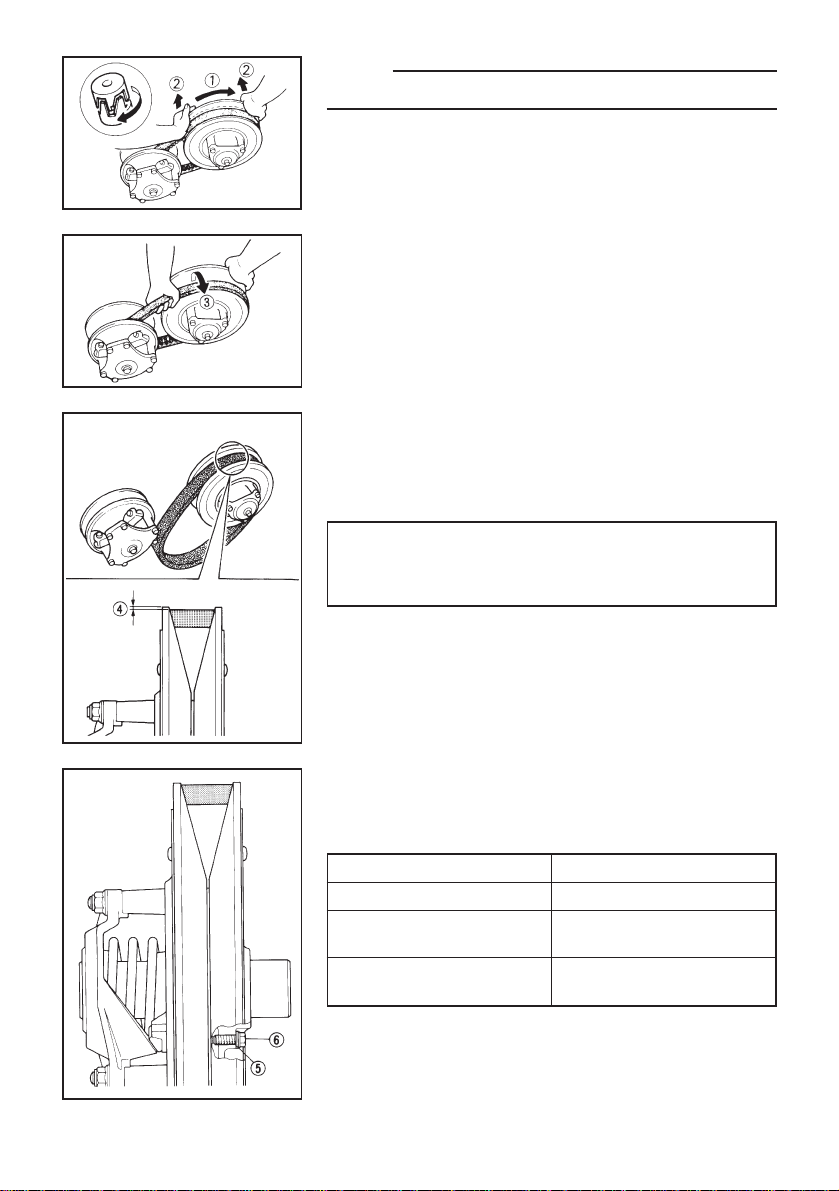
NOTE:
Apply the parking brake before replacement.
1. Remove the drive V-belt guard.
805-099
805-100
805-107
2. Rotate the secondary sliding sheave clockwise 1 and
push 2 it so that it separates from the fixed sheave.
3. Pull 3 the belt up over the secondary fixed sheave.
4. Remove the belt from the secondary sheave and
primary sheave.
5. Put the new V-belt back on the secondary sheave only.
Do not force the V-belt between the sheaves; the
sliding and fixed sheave must touch each other. Measure the V-belt position.
Standard V-belt position 4:
Below the sheave edge
0 ~ 2 mm (0 ~ 0.08 in)
805-092
6. If the position is incorrect, adjust the V-belt position by
removing or adding a spacer 5 on each adjusting
bolt 6.
V-belt position
Above the edge
Below the edge
0 ~ 2 mm (0~ 0.08 in)
Below the edge more
than 2 mm (0.08 in)
8-11
Adjustment
Remove spacer
Not necessary
(It is correct.)
Add spacer
Page 59

805-108
805-109
7. Tighten each adjusting bolt.
Adjusting bolts tightening torque:
10 Nm (1.0 m·kg, 7.2 ft·lb)
8. Install the V-belt over the primary sheave.
9. Rotate the secondary sliding sheave clockwise 7 and
push 8 it so that it separates from the fixed sheave.
10.Install the belt 9 between the secondary sliding and
fixed sheaves.
11. Install the drive V-belt guard.
WARNING
Never run the engine without the drive V-belt or with
the drive V-belt guard removed.
8-12
Page 60

ESS66901
DRIVE CHAIN HOUSING
Oil level checking
WARNING
The engine and muffler will be very hot after the engine
has been run.
Avoid touching the engine and muffler while they are
still hot with any part of your body or clothing during
inspection or repair.
1. Place the machine on a level surface.
2. Remove the dipstick 1 and wipe it off with a clean rag.
Then put the dipstick in the hole.
807-041
CAUTION
:
There is a magnet attached to the end of the dipstick. It
is used to remove any metal particles that may accumulate in the drive chain housing. When removing the
dipstick be sure to:
• Pull it out slowly and gently so the metal particles
do not fall off the magnet back into the drive chain
housing.
A
B
• Wipe off the magnet before reinserting the dipstick
into the drive chain housing.
807-036
807-044
807-043
3. Pull up the dipstick and check that the oil is between the
upper and lower levels. If not, add oil to the upper level.
1 Upper level
2 Lower level
Drive chain oil: API GL-3
SAE 75 or 80
Å For models without reverse transmissions
(PZ500/PZ500ML)
ı For models with reverse transmissions (VT500XL)
CAUTION
:
Be sure no foreign material enters the gear case.
4. Reinstall the dipstick and fit the loop 2 of the dipstick
handle onto the projection 1 of the gear case.
8-13
Page 61

Chain Tension Adjustment
1. Loosen the locknut.
2. Turn the adjuster bolt clockwise until it is finger-tight.
3. Hold the adjuster bolt in place while tightening the chain
adjuster locknut.
807-042
818-045
818-038
1 Locknut
2 Adjuster bolt
ESS61000
BRAKE
Checking Pad Wear
Check the brake pads for wear.
If the pads reach the wear limit, consult a Yamaha dealer
for replacement.
1 Wear indicator
Wear limit 2: 1.5 mm (0.06 in)
ESS61100
Checking the brake fluid level
Place the machine on a level surface. Check that the brake
fluid is above the lower level and replenish when necessary.
1 Lower level
Recommended brake fluid: DOT 4
WARNING
Be careful that water does not enter the master cylinder when refilling. Water will significantly lower the
boiling point of the fluid and may result in vapor lock.
If the brake fluid level goes down, consult a Yamaha
dealer.
CAUTION
Brake fluid may deteriorate painted surfaces or plastic
parts. Never spill any fluid. If any is spilled, clean it up
immediately.
:
8-14
Page 62

818-040
ESS61200
BRAKE FLUID REPLACEMENT
Brake fluid replacement is necessary when the following
components are replaced during the periodic maintenance
or if they are damaged or leaking.
a. All rubber seals of the master cylinder and caliper
cylinder
b. The brake system hose
WARNING
Be sure the brake fluid and the above parts are replaced by a Yamaha dealer.
ESS61400
PARKING BRAKE
Checking Pad Wear
Check the parking brake pads for wear by measuring the
thickness of the pads.
If the pads reach the wear limit, consult a Yamaha dealer
for replacement.
Wear limit 1: 1.0 mm (0.04 in)
818-070
818-071
Adjustment
As the pads wear, adjustment may be necessary to ensure
proper brake performance.
WARNING
Be sure this adjustment is made by a Yamaha dealer.
1. Loosen the locknut 1.
2. Turn the pad adjuster 2 in or out to adjust the clearance
between the pad 3 and disc 4.
Clearance 5: 1.2 ~ 1.3 mm (0.047 ~ 0.051 in)
3. Turn the cable adjuster 6 in or out to adjust the
clearance between the pad 7 and disc 4.
Clearance 8: 1.2 ~ 1.3 mm (0.047 ~ 0.051 in)
4. Tighten the locknut.
8-15
Page 63

ESS67000
SUSPENSION
The suspension can be adjusted to suit rider preference. A
softer setting, for example, may provide greater rider
comfort, while a stiffer setting may allow more precise
handling and control over certain types of terrain or riding
conditions.
WARNING
Be sure this adjustment is made by a Yamaha dealer.
ESS67510
Ski Spring Preload
The spring preload can be adjusted by turning the
adjuster 1.
PZ500/VT500XL
819-067
819-062
Spring adjuster position
Preload
Standard
54321
2 Harder Softer 3
2
PZ500ML
Spring adjuster position
Preload
Standard
CAUTION
:
54321
2 Harder Softer 3
1
Be sure the left and right spring preload is the same.
8-16
Page 64

ESS68010
Rear Suspension Spring Preload
The spring preload can be adjusted by turning the
adjuster 1.
WARNING
Be sure this adjustment is made by a Yamaha dealer.
A
820-061
B
820-097
C
820-071
D
PZ500
Spring adjuster position
Preload
Å Standard (Front)
PZ500ML
Spring adjuster position
Preload
ı Standard (Front)
VT500XL
Spring adjuster position
Preload
Ç Standard (Front)
PZ500/PZ500ML/VT500XL
Spring adjuster position
12345
Softer Harder
2
12345
Softer Harder
1
12345
Softer Harder
3
1234567
820-062a
Preload
Î Standard (Rear)
8-17
Softer Harder
4
Page 65

ESS68510
FULL RATE ADJUSTER
The total suspension spring rate and damping characteristics can be adjusted by changing the installed position of
the shock-absorber assembly.
WARNING
Be sure this adjustment is made by a Yamaha dealer.
820-065
820-088
820-087
Installation position
Spring rate and damping
Standard
CBA
Hard Medium Soft
B
NOTE:
Be sure to make this adjustment when there is no load
(rider or cargo) on the snowmobile.
1. Loosen the nut 1 1/2 or 3/4 turns, while holding the
adjusting bolt 2 securely with a wrench so it does not
move.
CAUTION
Never allow the adjusting bolt 2 to move while loosening the nut.
2. Turn the adjusting bolt 2 to the desired position.
CAUTION
Be sure the adjusting bolt ends are set at the same
position on each side.
3. While holding the adjusting bolt securely, tighten the
nut 1.
:
:
Nut tightening torque: 49 Nm (4.9 m·kg, 35.4 ft·lb)
CAUTION
Never allow the adjusting bolt to move while tightening the nut.
:
8-18
Page 66

ESS59801
TRACK ADJUSTMENT
WARNING
A broken track, track fittings, or debris thrown by the
track could be dangerous to an operator or bystanders.
Observe the following precautions:
• Do not allow anyone to stand behind the machine
when the engine is running.
• When the rear of the machine is raised to allow the
track to spin, a suitable stand must be used to
support the rear of the machine. Never allow anyone to hold the rear of the machine off the ground
to allow the track to spin. Never allow anyone near
a rotating track.
• Inspect the track condition frequently. Replace
damaged track guide clips. Replace the track if it is
damaged to the depth where fabric reinforcement
material is visible or support rods are broken. Otherwise, track damage and/or failure could result in
loss of braking ability and machine control, which
could cause an accident.
• Never install studs (cleats) closer than three inches
from the edge of the track.
820-003
Track Deflection Measurement
1. Lay the machine on its side.
2. Measure the track deflection with a spring scale. Pull at
the center of the track with a force of 100 N {10 kg
(22 lb)}.
NOTE:
Measure the gap between the slide runner and the edge of
the track window. Measure both sides.
1 Deflection
2 100 N {10 kg (22 lb)}
Standard track deflection:
PZ500/VT500XL
25 ~ 30 mm (0.98 ~ 1.18 in)/100 N {10 kg (22 lb)}
PZ500ML
20 ~ 25 mm (0.79 ~ 0.98 in)/100 N {10 kg (22 lb)}
3. If the deflection is incorrect, adjust the track.
8-19
Page 67

Track Adjustment
WARNING
• Be sure this adjustment is made by a Yamaha
dealer.
• Support the machine securely on a suitable stand
before working underneath the machine.
• Operate the engine in a well-ventilated area.
1. Lift the rear of the machine onto a suitable stand to raise
the track off the ground.
2. Loosen the rear axle nut 1.
6 7
820-076
820-008
820-005
820-009
NOTE:
It is not necessary to remove the cotter pin 2.
3. Start the engine and rotate the track one or two turns.
Stop the engine.
4. Check the track alignment with the slide runner 3.
If the alignment is incorrect, turn the left and right adjusters
to adjust.
Track alignment
4 Left adjuster
5 Right adjuster
8 Slide runner
9 Track
0 Track metal
A Gap
B Forward
6 Shifted to
right
Turn out
Turn in
7 Shifted to
left
Turn in
Turn out
5. Adjust track deflection to the specified amount.
Track deflection
4 Left adjuster
5 Right adjuster
8-20
More than
specified
Turn in
Turn in
Less than
specified
Turn out
Turn out
Page 68

CAUTION
:
The adjusters should be turned an equal amount.
6. Recheck alignment and deflection. If necessary, repeat
steps 3 to 5 until the proper adjustment is achieved.
7. Tighten the rear axle nut.
Rear axle tightening torque:
75 Nm (7.5 m·kg, 54.2 ft·lb)
ESS62900
SKI ALIGNMENT
1. Turn the handlebars so the skis face straight ahead.
2. Check the following for ski alignment:
1) Ski is facing forward.
2) Ski toe-out (1 - 2) is within specification.
819-001
845-024
819-072
Ski toe-out (1 - 2): 0 ~ 15 mm (0 ~ 0.59 in)
3. If the alignment is not correct, consult a Yamaha dealer.
ESS63000
HANDLEBAR ADJUSTMENT (PZ500/VT500XL)
1. Remove the handlebar cover 1.
2. Loosen the handlebar bolts. Move the handlebar assembly up or down to adjust the handlebar height to the
desired position.
3. Tighten the handlebar bolts and install the handlebar
cover.
Handlebar bolt tightening torque:
14.5 Nm (1.45 m·kg, 10.5 ft·lb)
8-21
Page 69

819-040
845-063
819-070
CAUTION
:
Be sure the small gap 1 side of the holder faces
forward 2.
ESU00236
HANDLEBAR ADJUSTMENT (PZ500ML)
1. Remove the handlebar cover 1.
2. Loosen the handlebar bolts.
3. Move the handlebar up or down (± 7°) to adjust the
handlebar height to the desired position.
819-082
819-086
819-083
CAUTION
:
Be sure the projection on the handlebar is not installed
into the area a shown.
8-22
Page 70

819-081
4. Tighten the handlebar bolts and install the handlebar
cover.
Handlebar bolt tightening torque:
23 Nm (2.3 m·kg, 17 ft·lb)
CAUTION
:
Be sure the small gap b side of the handlebar holders
faces forward c.
ESS66601
LUBRICATION
Lubricate the following points.
Lubricant: Low-temperature grease
2
2
3
820-095
820-067
1 Throttle cable ends
WARNING
Apply a dab of grease onto the cable end only.
Do not grease the brake/throttle cables themselves
because they could become frozen, which could cause
loss of control.
2 Front suspension
3 Rear suspention
820-082
820-093
8-23
Page 71

832-034
832-008
ESS64501
HEADLIGHT
Bulb Replacement
1. Lift up the shroud.
2. Disconnect the lead coupler.
3. Remove the bulb cover.
4. Remove the bulb holder by depressing and turning it
counterclockwise.
1 Bulb cover
5. Remove the bulb.
WARNING
Keep flammable products or your hands away from
the hot bulb until it cools down.
6. Install the new bulb.
Bulb type: 12 V, 60/55 W
832-007
832-033
CAUTION
:
Keep oil or your hands away from the glass part of bulb
or its life and illumination will be affected.
If the glass is oil stained, thoroughly clean it with a
cloth moistened with alcohol or lacquer thinner.
Beam Adjustment
1. Turn the adjuster 1 in or out to adjust the headlight
beam.
Beam moves:
2 Down and to the left
3 Up and to the right
4 Down and to the right
5 Up and to the left
8-24
Page 72

830-002
ESS65800
BATTERY (VT500XL)
Replenishing the battery fluid
1. Check the fluid level. The level should be between the
upper and lower level marks.
1 Upper level
2 Lower level
2. Add only distilled water if necessary.
CAUTION
:
Normal tap water contains minerals which are harmful
to a battery; refill only with distilled water.
WARNING
Battery electrolyte is poisonous and dangerous. If
contains sulfuric (sulphuric) acid and can cause severe burns. Avoid contact with the skin, eyes or clothing.
Antidote:
EXTERNAL-Flush with water.
INTERNAL-Drink large quantities of water or milk.
Follow with milk of magnesia, beaten egg or vegetable
oil. Call physician immediately.
Eyes:
Flush with water for 15 minutes and get prompt medical attention.
Batteries produce explosive gases. Keep sparks, flame,
cigarettes, etc. away. Ventilate when charging or using in closed space. Always cover eyes when working
near batteries. KEEP OUT OF REACH OF CHILDREN.
8-25
Page 73

ESS65900
FUSE REPLACEMENT (VT500XL)
WARNING
Be sure to use the specified fuse. A wrong fuse will
cause electrical system damage and can be A FIRE
HAZARD.
835-007
CAUTION
Be sure the main switch is turned off to prevent
accidental short circuiting.
1. Lift up the shroud.
2. Replace the blown fuse with a fuse of the proper
amperage.
:
NOTE:
If the fuse immediately blows again, consult a Yamaha
dealer.
Fuse type: 10 A
8-26
Page 74

ESS65300
TROUBLESHOOTING
A. Engine turns over but doesn’t start
1. Fuel System
No fuel supplied to combustion chamber
• No fuel in tank ... Supply fuel.
• Clogged fuel line ... Clean fuel line.
• Clogged carburetor ... Clean carburetor.
Fuel supplied to combustion chamber.
• Flooded engine (too much choke) ... Crank
engine with throttle open or wipe spark
plug dry.
2. Electrical System
Poor or no spark
• Spark plug dirty with carbon/wet ... Re-
move carbon/wipe spark plug dry, or replace spark plug.
• Faulty ignition system ... Consult dealer.
• T.O.R.S. system malfunction ... Discon-
nect the carburetor switch connectors
and connect the wire harness connectors
together to bypass T.O.R.S.
3. Compression
Insufficient
• Loose cylinder head nuts ... Tighten nuts
properly.
• Damaged gasket ... Replace gasket.
• Worn out piston and cylinder ... Consult
dealer.
B. Engine does not turn over with
manual starter
1. Seized engine ... Seizure is caused by
poor lubrication, inadequate fuel, or an
air leak –– Consult dealer.
2. “Hydrolock” (fuel has filled crankcase
when vehicle was transported) ... Remove spark plug(s), turn engine over
several times with ignition off to expel
excess fuel. Consult dealer.
C. Electric starter does not operate or
operates slowly (VT500XL)
1. Faulty wire connections ... Check connections or consult dealer.
2. Battery discharged ... Check battery fluid
and charge battery.
3. Engine trouble ... Check B above.
816-022
WARNING
• Before bypassing the T.O.R.S., be sure
the throttle returns properly to the
fully-closed position.
• The T.O.R.S. is an important safety
device; in the case of a malfunction,
take the machine to a Yamaha dealer
immediately for repair.
D. Engine power is low
1. Faulty spark plug(s) ... Clean or replace
spark plug(s).
2. Jetting incorrect for altitude or temperature ... carburetor. Consult dealer.
3. Improper fuel flow ... See A.1. above.
4. Clutch settings not correct for altitude
and/or conditions ... Consult dealer.
E. Engine constantly backfires or mis-
fires
1. Faulty spark plug(s) ... Replace spark
plug(s).
2. Fuel system clogged ... See A.1. above.
3. T.O.R.S. malfunction ... See T.O.R.S. in
A.2. above.
9-1
Page 75

F. Machine does not move
1. Clutch malfunction ... Consult dealer.
2. Drive track does not move ... Foreign
object is caught in track, or slide runner
has melted to track metal due to lack of
lubrication.
3. Drive chain too tight, too loose, or broken
... Consult dealer.
G. Drive belt twists
1. Improper belt ... Replace with correct
belt.
2. Clutch offset incorrect ... Consult dealer.
3. Engine mount loose or broken ... Consult
dealer.
H. Drive belt slips or burns
1. Belt or sheave surface oily or dirty ...
clean.
2. Problem with drive line ... See F above.
I. Engine does not upshift or downshift
properly/engages harshly
1. Drive belt worn ... replace belt or consult
dealer.
2. Clutch settings incorrect for altitude/conditions ... Consult dealer.
3. Primary clutch worn or sticking ... Consult
dealer.
4. Secondary clutch worn or sticking ... Consult dealer.
J. Noise or excessive vibration in drive
line
1. Broken clutch components ... Consult
dealer.
2. Worn or damaged bearings ... Consult
dealer.
3. Drive belt damaged or worn with flat
spots ...Replace.
4.Idler wheel/shaft damage ... Consult
dealer.
5. Track damaged ... Consult dealer.
9-2
Page 76

ESS70303
STORAGE
Long term storage, requires some preventive procedures to guard against deterioration.
1. Cleaning
Thoroughly clean the machine, inside
and out, to remove the corrosive salts
and acids that can accumulate. Use
Yamaha Mud and Grease Release, or an
equivalent, to loosen mud, grease and
grime. Wash with mild soap, then rinse
and dry completely.
shaft from corrosion. An alternate method
is to remove the airbox and squirt oil into
the carburetor throats while the engine is
running.
CAUTION
Do not attempt to store the machine by
simply starting the engine occasionally
during the storage period. This can cause
more harm than good! Moisture and acids form during combustion which can
actually increase the chance for corrosion damage during the storage period.
:
2. Lubrication
Lubricate moving parts, suspension linkage and pivot points. Use the grease or
lubricant specified in the MAINTENANCE
section, or Yamaha Lube-Zall general
purpose lubricant. Proper lubrication fights
corrosion while it reduces friction.
3. Fuel System Preparation
Add Yamaha Fuel Conditioner/Stabilizer,
or an equivalent, to the fuel tank to help
prevent fuel oxidation, gum and varnish
deposits, and to inhibit corrosion in the
fuel system and carburetor. In areas
where oxygenated fuel (“gasohol”) is
used, completely drain the fuel system.
Consult your Yamaha dealer.
4. Engine
Proper storage of the engine is essential
to prevent costly rust and corrosion damage to internal engine components. This
is more important than ever in those
areas where oxygenated fuel (“gasohol”)
is used, because the alcohol content in
the fuel increases the chance for water to
enter the engine. Use Yamaha Stor-Rite
Fogging Oil, or an equivalent, to protect
both combustion chamber and crank-
5. Protection
Apply a coat of wax, such as Yamaha
Silicone Wax, to painted surfaces. Spray
Yamaha Silicone Spray, or an equivalent
protectant, on the exterior of the engine,
on the track, and on other metal, plastic
and rubber parts.
6. Battery (VT500XL)
Remove the battery from the machine
and check the fluid level. Charge the
battery. Store it in a cool, dry place that is
above 0°C (32°F), but less than 30°C
(90°F). Check battery condition with a
hydrometer monthly, and charge as necessary.
WARNING
• Never smoke or make and break con-
nections at the battery while charging.
Sparks may ignite the battery gas.
• Be sure the battery terminals are tight
and that the battery vent tube is properly routed and is securely attached to
the battery.
10-1
Page 77

CAUTION
Do not charge battery quickly. Charge for
10 hours at 1.6 amperes.
7. Track
Loosen the track, and block up the
chassis so that the track is suspended
above the ground.
8. Drive Belt
Remove the drive belt and store separately.
9. Storage
Store the machine in a dry, well-ventilated place out of direct sunlight. Put a
fabric (breathable) cover over it, preferably one designed for your machine. Do
not use a plastic or vinyl cover — condensation could be trapped underneath which
could increase the chance of rusting.
RETURN TO SERVICE AFTER STORAGE
:
When returning your machine to service,
reinstall the drive belt and adjust the track.
Reinstall the battery, and make sure that the
battery vent tube is properly reinstalled and
is not kinked.
Remove the spark plugs and clean them or
replace them. Perform all other pre-operation and seasonal maintenance listed in the
Periodic Maintenance chart.
For peak performance, it is recommended
that you have your machine checked and
tuned by your Yamaha dealer. He has the
experience and training to help you get the
maximum performance and use from your
Yamaha.
10-2
Page 78

ESG73000
ESS73200
DIMENSIONS
Overall length
Overall width
Overall height
Dry weight
Ski tread
ESS75100
ENGINE
Type
Cylinder arrangement
Displacement
Bore × Stroke
Idle speed
Engine oil pype
Carburetor pype
Fuel
Starting system
SPECIFICATIONS
PZ500/PZ500ML/VT500XL
2760 mm (108.7 in): PZ500
2970 mm (116.9 in): PZ500ML/VT500XL
1200 mm ( 47.2 in): PZ500/VT500XL
1120 mm ( 44.1 in): PZ500ML
1230 mm ( 48.4 in): PZ500/PZ500ML
1330 mm ( 52.4 in): VT500XL
211 kg ( 465 lb): PZ500
220 kg ( 485 lb): PZ500ML
244 kg ( 538 lb): VT500XL
1070 mm ( 42.1 in): PZ500/VT500XL
980 mm ( 38.6 in): PZ500ML
PZ500/PZ500ML/VT500XL
Axial fan cooled 2-stroke, 7-port
Parallel 2-cylinder
3
485 cm
72.0 × 59.6 mm (2.83 × 2.35 in)
1300 ± 100 r/min
YAMALUBE 2-cycle oil
MIKUNI, B38-32 × 2
Unleaded gasoline
Pump octane
Manual with recoil starter:
PZ500/PZ500ML
Electric and manual with recoil starter:
VT500XL
R + M
2
; 88 or higher
11-1
Page 79

ESS77200
CHASSIS
Drive track and suspension:
Track
Width
Track deflection
Molded rubber, fiber glass rod reinforced
381 mm (15.0 in)
25 ~ 30 mm (0.98 ~ 1.18 in)/
100 N {10 kg (22 lb)}: PZ500/VT500XL
20 ~ 25 mm (0.79 ~ 0.98 in)/
100 N {10 kg (22 lb)}: PZ500ML
Length on ground
752 mm (29.6 in): PZ500
944 mm (37.2 in): PZ500ML/VT500XL
Suspension type
Drive sprocket
Slide rail suspension
Double polyethylene, 9 teeth: PZ500
Quadruple polyethylene, 8 teeth:
PZ500ML/VT500XL
Transmission:
Type
Automatic centrifugal engagement,
infinitely variable 3.8:1 ~ 1:1
Sheave distance
Sheave offset
Engagement speed
✽
Approx. 268.5 mm (10.57 in)
Approx. 15 mm (0.59 in): PZ500/PZ500ML
Approx. 20 mm (0.78 in): VT500XL
Approx. 3800 r/min: PZ500
Approx. 4100 r/min: PZ500ML
Shift speed
✽
Drive chain
Reduction ratio
Approx. 3700 r/min: VT500XL
Approx. 7250 r/min
Silent chain enclosed in oil bath
39/21 (1.86): PZ500/VT500XL
39/18 (2.17): PZ500ML
Fuel tank:
Tank capacity
44.3 L (9.7 lmp gal, 11.7 US gal)
Oil tank:
Tank capacity
3.3 L (2.9 lmp qt, 3.5 US qt)
Brake:
Type
Operation
Hydraulic disc type
Handle lever, left hand operated
Throttle:
Operation
✽
Subject to change according to elevation settings.
Handle lever, right hand operated
PZ500/PZ500ML/VT500XL
11-2
Page 80

ESS78100
ELECTRIC
Ignition system
Spark plug Type
Gap
Battery Capacity
Maximum charge rate
Headlight Bulb × Quantity
Tail/brake light Bulb × Quantity
Meter light Bulb × Quantity
Indicator light Bulb × Quantity
PZ500/PZ500ML/VT500XL
CDI
BR9ES (NGK)
0.7 ~ 0.8 mm (0.028 ~ 0.031 in)
YB16AL-A2/12 V 16A·h: VT500XL
1.6 Amperes/hr for 10 hrs: VT500XL
12 V, 60/55 W × 1
12 V, 8/23 W × 1
12 V, 1.7 W × 2
12 V, 3.4 W × 2
11-3
Page 81

A
MAIN HARNESS HEAD LIGHT
B
MAIN HARNESS SUB HARNESS
C
SUB HARNESS
CORD TAIL LIGHT
D
MAIN HARNESS WIRE SUB LEAD
LGY
BR/B
YGL
R/BB
Br W
BLY/B
W
Y/B
Br
YB
W/G
W/RW/R
W/G
L
G/Y
B
L
G/Y
B
L
G/Y
B
B
R/B
Gy
Br
Y/W
B/R
Y/W
B/R
L
G/Y
B
Y/R
Y/B
G/R
L
B
RR/W
B
R/WR
Ch
B/YB/W
B
B/WB/Y
OFF
ON 1
ON 2
START
HI
LO
RUN
OFF
OFF
OPEN
OFF
ON
RUN
IDLE
B
R
Y/B
Br
B/W
R/W
Y/R
B/W
R/W
Y/R
Br
B
R
Y/B
B
R/B
L
Y
G
L
Y
G
B
R/B
R
R/W
B
WB
RL
B/RBY/R
Y/W
R
B
R
B
B
Y/R
B
W
G/Y
L
G/Y
L
YG
L
GY
L
G/R
R
G/R
R
O
B/WW/G
Br B/YB
(BLACK)
(BLUE)
(L)
(L)
(R)
(R)
YB
G
Br
P
Br
P
L
G/Y
B
L
G/Y
B
OFF
ON
1
4
3
5
6
7
89
0
F
E
G
HH
I
J
K
L
M
N
O
P
Q
R
S
T
U
V
W
L
A
B
C
D
2
W/G
Br
B LW
RL
B
L
Y G
L L L
W
Y/B
R/B
B/R
Y/R
Y/R
W/R
R/W
R/W
R/W
W/G
Br
B/W
B/Y
Y/W
B/R
B/Y
Y/R
Y/W
L L
G/Y
G/Y
G G G
Y Y Y
B
B
B
L
L
L
L
L
G/R
G/Y
G/R
R
R
B
G/Y
G/Y
G/Y
BBBBB
R/B
G
Y
Y
B
G
B
R/B
R/B
B
B
P
P
Br
B
Y/R
B
Br
B
Ch
B/Y
O O
B
B
Ch
B
BB
B/W
Y/B
R B/WR/W
B
B
B
B
B
R
R
R
R
R
B
D
D
D
B
C
B
C
C
B
A
A
A
A
A
12-1
WIRING DIAGRAM
Page 82

COLOR CODE
B............... Black
Br.............. Brown
Ch............. Chocolate
G .............. Green
Gy............. Gray
L ............... Blue
O .............. Orange
P............... Pink
R............... Red
(VT500XL)
K Passenger warmer switch
L Passenger warmer (VT500XL)
M DC back buzzer (VT500XL)
N Gear position switch (VT500XL)
O Headlight
P Oil level switch
Q Meter assembly
R Oil level light
S High beam light
W.............. White
Y............... Yellow
B/R ........... Black/Red
B/W .......... Black/White
B/Y ........... Black/Yellow
G/R........... Green/Red
G/Y ........... Green/Yellow
T Speedometer light
U Tachometer light
V Tachometer
W Headlight beam switch
R/B ........... Red/Black
R/W .......... Red/White
W/G .......... White/Green
W/R .......... White/Red
Y/B ........... Yellow/Black
Y/R ........... Yellow/Red
Y/W .......... Yellow/White
1 CDI magneto
2 Rectifier/regulator
3 Fuse (VT500XL)
4 Starter relay (VT500XL)
5 Battery (VT500XL)
6 Starter motor (VT500XL)
7 Main switch
8 Engine stop switch
9 Accel switch
0 Carburetor switch
A CDI unit
B Ignition coil
C Spark plug
D Ground
E Voltage regulator
F Variable resistor
G Thumb warmer
H Grip warmer
I Brake light switch
J Tail/brake light
12-2
Page 83

PRINTED ON RECYCLED PAPER
PRINTED IN JAPAN
99 · 4 - 1.8 × 4 CR
 Loading...