

Page 1

YAMAHA
AUTHORIZED
PRODUCT MANUAL
P-2200/2201
SYSTEM AMPLIFIER
Page 2

P-2200/2201
OPERATING MANUAL
Page 3

ABOUT THIS MANUAL
SCOPE
The P-2200 is a system oriented amplifier, made to be
used in conjunction with mixers, consoles, frequency
dividing networks and speakers — those made by
Yamaha or by other manufacturers. Like any power
amplifier, the P-2200's performance depends on system
design and installation, in addition to its own capabilities.
Thus, the P-2200 Operating Manual is system oriented,
describing system design parameters and installation
techniques, as well as the operation and performance of
the P-2200.
Additionally, this manual reviews a few of the basic
mathematic tools used in system design, from dB to
Ohm's law.
ORGANIZATION
We recommend that you read the entire Operating
Manual. However, if you are using the P-2200 in an
existing system, and you are familiar with high power
amplifiers, the BRIEF OPERATING INSTRUCTIONS,
Pages
One 1 &
basic connections and operation.
The SPECIFICATION sections, (Sections THREE
and FOUR) are highly detailed, including oscilloscope
photos, and discussions of the P-2200's excellent
performance specifications. The last part of the
SPECIFICATIONS section is a discussion of the
advantages of professional equipment, like the P-2200,
compared to hi-fi or semi-pro equipment.
The INSTALLATION AND DETAILED
OPERATION section, which begins on Page SIX 1,
includes more complete instructions, special considerations for using the P-2200 "on the road," as well as in
permanent commercial and studio installations. This
section also covers grounding and shielding concepts,
cabling considerations, and several other topics.
The APPLICATIONS section, which begins on Page
SEVEN 1, discusses the use of the P-2200 in several
typical setups, and includes wiring diagrams. This section
also covers other devices that are normally associated
with a power amplifier, from graphic equalizers to
compressor/limiters.
The APPENDIX, on Page EIGHT 1, discusses
definitions of a number of the terms used in the manual,
and reviews some of the basic mathematic tools used in
system design, such as the dB, Ohm's law, voltage
division, and power formulas.
2,
contain all the
information
necessary
for
NOTE: The P2201 is identical to the P-2200 except
there are no Peak Reading Meters.
Page 4

THE P-2200/2201 BRIEF OPERATING INSTRUCTIONS SECTION ONE
INTRODUCTION SECTION TWO
GENERAL SPECIFICATIONS SECTION THREE
PERFORMANCE GRAPHS & A DISCUSSION OF SPECIFICATIONS SECTION FOUR
THE DISTINCTION BETWEEN PROFESSIONAL AND HI-FI EQUIPMENT SECTION FIVE
IMPEDANCE
OPERATING LEVELS
DYNAMIC RANGE
GAIN OVERLAP AND HEADROOM
INPUT SENSITIVITY RATINGS
PROFESSIONAL EQUIPMENT ADVANTAGES
INSTALLATION AND DETAILED OPERATION
SECTION SIX
PHYSICAL MOUNTING
CABLING AND IMPEDANCE MATCHING
ACTIONS OF THE P-2200 PROTECTION CIRCUITS
GROUNDING AND SHIELDING
AC: POWER, FUSES, ACCESSORY OUTLETS, WIRING, SAFETY
MONO OPERATION
APPLICATIONS
SECTION SEVEN
13
13
16
17
BIAMPLIFICATION AND TRIAMPLIFICATION
ECHO, REVERB AND DELAY
COMPRESSION AND LIMITING
EQUALIZATION, HIGH AND LOW PASS FILTERS
SPEAKER PROTECTION
SPECIFIC APPLICATIONS
APPENDIX
SECTION EIGHT
DEFINITION OF TERMS: dB, dBV, dBm and dB SPL
SPECIAL USE OF dB (VOLTS) IN THIS MANUAL
OHM'S LAW
POWER
IMPEDANCE
SERIES AND PARALLEL IMPEDANCE CONNECTIONS
VOLTAGE AND CURRENT DIVISION
BALANCED, UNBALANCED, AND FLOATING CIRCUITS
TRANSFORMERS
1
2
2
4
4
4
1
2
1
3
3
4
6
7
1
1
2
2
3
3
4
5
5
Page 5
THE P-2200/2201 BRIEF OPERATING INSTRUCTIONS
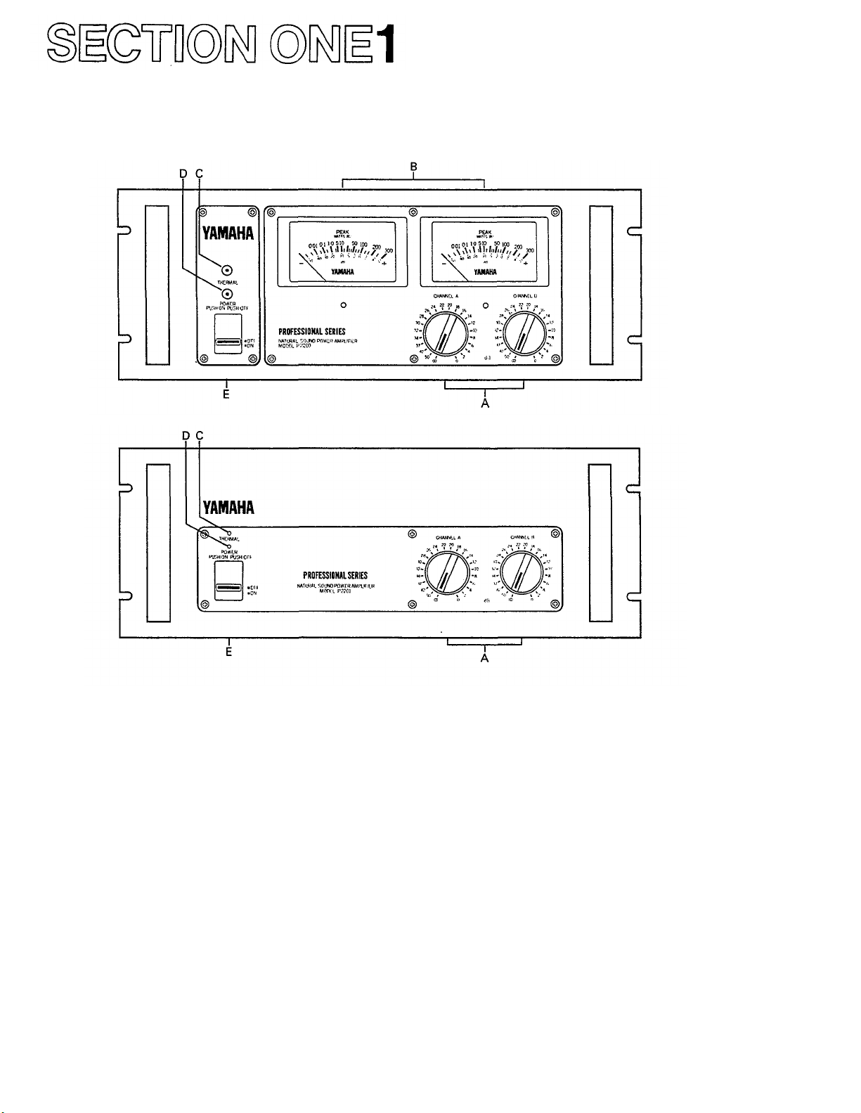
Fig. 1A - P-2200 Front Panel
Fig. 1B - P2201 Front Panel
A. Input Attenuators
Calibrated, stepped input attenuators lower input
signal levels ahead of amplification stages.
B. Peak Reading Meters (P-2200 only)
Meters display instantaneous (peak) power output
into
an
8-ohm load
over a full
50dB range;
"0dB"
=
100 Watts into 8 ohms.
C. Thermal Warning Indicator
Warns of overheating before thermal protection
circuit turns off the AC power.
D. Power Indicator
Glows when the power switch is "on."
E. On-Off Switch
Controls AC power to the P-2200 or P2201.
NOTE: The P2201 is identical to the P-2200 except
there are no Peak Reading Meters. Both are made to be
mounted in a standard 19" wide electronic equipment
rack. Each of them takes up 7" (17.6cm) of vertical
space, and extends 13" (33.0cm ) behind its front panel.
For portable racks, we recommend bracing the rear of
the amplifiers.
Page 6
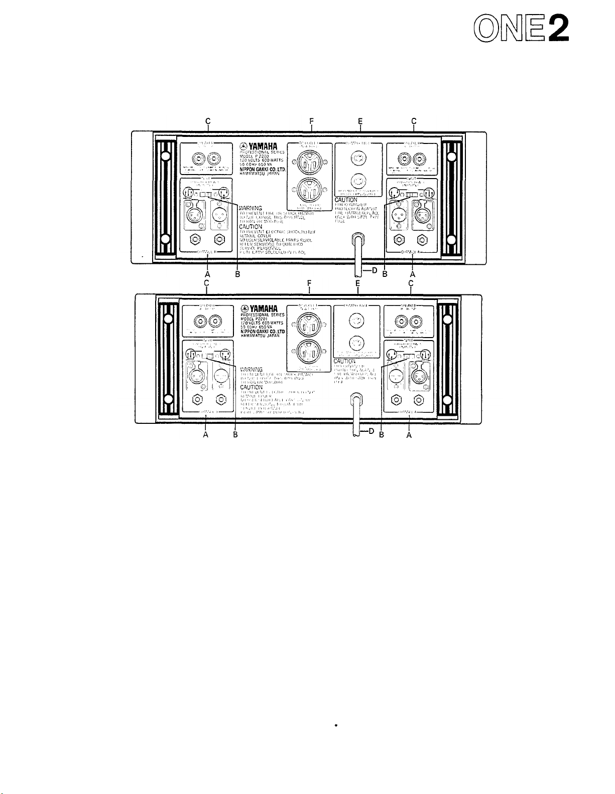
Fig. 2A - P-2200 Rear Panel*
Fig. 2B - P2201 Rear Panel*
A. Input Connectors
The two XLR input connectors on each channel are
unbalanced and are wired in parallel with each other
and with the two phone jacks (tip/sleeve type).
B. Input Polarity Switch
Determines the polarity of the two XLR input
connectors (Pin 2 or Pin 3 "
hot
");
does
not
affect
the
two phone jacks. See diagram on the rear panel.
NOTES:
1. Input impedance is 25k-ohms minimum; +4dB
(1.23V) produces 230 watts output into 8 ohms
(44.7V).
2. Input channels may be parallelled by connecting
them together with phone to phone or XLR to XLR
cables as shown on Page SIX 7.
3. Input transformers for matching or isolation,
should be located several inches from the P-2200 or
P2201's power transformer
C. Output Connectors
Standard 5-way binding posts (3/4" spacing) accept
banana plugs or direct-wired connections.
NOTES:
1. Maximum power output into 8 ohms is 230 watts;
power output rises at lower impedances.
2. Protection circuitry towers power output when
load impedance falls below 2.5 ohms.
for
maximum
hum
rejection.
D. AC Power Cord
For the U.S. and Canadian models, the P-2200/2201
require 117 VAC 50 or 60 Hz line (105 V min., 135 V
max.; 8 amps max. at 120 volts).
For the Australian model: 240V AC 50 or 60 Hz.
For other territories' models, an internal voltage
selector (220 V/240 V switchable) is provided near the
rear panel. In this case 220 V is factory-preset. If you
want
to
change
into
240 V line,
consult
your
nearest
Yamaha dealer.
E. Fuses
7 amp, 125 volt (x 2), type AGC (3AG); U.S. and
Canadian models only. 4 amp, 250 volt (x 2); other
territories models. Fuses should always be replaced
with
same
size
and
type.
If
the
fuses
blow
consistently,
the amplifier should be checked by a qualified Yamaha
service technician.
F. AC Accessory Outlets
These convenience outlets are made for low power
cooling fans. Not provided in certain areas.
The rear panels shown here are subject to U.S. specifications.
Page 7

INTRODUCTION
The P-2200 is not just "another big amplifier;" it is
an exciting new approach to high power sound. Yamaha's
leadership is clearly demonstrated by the P-2200's professional features, sophisticated design, and uncompromising performance.
PEAK READING METERS*
Instead of the more common and slow responding
VU meters, the P-2200 has PEAK READING METERS
that
accurately display a full
output level. The peak meters have large, illuminated
faces marked with dB and with watts into 8 ohms. The
fast responding meters provide a better way to see the
program dynamics, the transient power demands placed
on the system, and the available headroom. By indicating
headroom, the meters help the operator avoid overdriving the system, thereby preventing the "clipped"
waveforms so dangerous to drivers and loudspeakers.
CALIBRATED INPUT ATTENUATORS
The P-2200 has log-linear INPUT ATTENUATORS to
complement its peak reading meters. The input attenuators are marked in 22dB-calibrated steps, detented for
extra accuracy. The attenuators provide a smooth, noise
free transition from the highest to the lowest audio level.
dB-calibrated
advantages: on the road, they allow predictable and
repeatable setups; in commercial sound applications,
they allow easy, accurate input sensitivity adjustments;
in studios or discos, they let operators simultaneously
adjust the level of two channels (or two programs on
separate amplifiers) with precise tracking.
INPUT AND OUTPUT CONNECTIONS
INPUT CONNECTORS for each channel include one
"male" and one "female" XLR connector (unbalanced)
plus two parallel phone jacks. This provides the flexi-
bility
necessary
amplifier, as well as for adapter-free connection to
almost any mixer. A POLARITY switch allows either
pin 2 or pin 3 of the XLR to be chosen as the "hot"
lead, satisfying DIN/JIS or USA standards. Outputs are
standard five way binding posts, usable with high current
"banana" plugs or direct wired connections.
MONAURAL OPERATION
The P-2200 may be converted to a monaural "super
amplifier" by inserting two matched transformers
ahead of the inputs, feeding the same signal to both,
and reversing the POLARITY switch on one input. This
creates a transformerless balanced output, the speaker
load "bridged" across the "hot" terminals of both
channels. In this mode, the P-2200 is suitable for
driving almost any load, including highly reactive 70-volt
commercial speaker lines. With a full 400 watts into
16 ohms, the P-2200 in mono mode eliminates the need
for several smaller 70-volt amplifiers.
input
attenuators
for
convenient bridging
five
have
decades
numerous
to
(50dB)
another
of
PERFORMANCE
The P-2200's performance is as impressive as its
features. At a sustained output of 230 watts into 8 ohms
(for each channel), there is plenty of punch to reproduce
the powerful peaks essential to clean studio monitoring.
High power handling also makes the P-2200 an unbeatable choice for live rock or disco sound systems, where
an amplifier can really "cook" all night long. Power alone
is
no
virtue;
the P-2200
0.05% THD at full rated power - the kind of low
distortion that is undetectable by even the most critical
listeners.
A high damping factor of better than 300 at
frequencies below 1kHz reduces the tendency for
speaker cone overshoot, giving tighter and better defined
bass response. On the other end, the P-2200's frequency
response extends well beyond 100kHz, enabling it to
accurately reproduce the most complex musical waveforms — even the tortuous output of today's synthesizers. However, high frequency response has not been
achieved at the expense of stability; in fact, the P-2200
is rock steady. Even when connected to highly reactive
multi-speaker loads, there is no tendency to shut down
or "take off" into spurious oscillation.
MECHANICAL CONSIDERATIONS
The P-2200 is constructed to withstand the high "G"
forces encountered on the road. Its solid front panel
mounts in any standard 19-inch rack, and, for a large
amplifier, the P-2200 weighs a modest 44 pounds
(20kg)** Front panel controls and meters are recessed to
avoid damage or accidental setting changes, and are
further protected by a pair of sturdy carrying handles.
Inside
and
out,
the P-2200
should
service
ever
easy access. Massive side-mounted heat sinks are
designed for efficient cooling, making fans unnecessary
in all but the most severe thermal operating conditions.
Four non-conductive feet ensure proper air flow when
the amplifier is shelf mounted, and avoid inadvertent
ground loops. Multiple protection circuits make the
amplifier nearly abuse proof and eliminate the need for
troublesome DC power supply fuses.
* The P2201 does not have the Peak Reading Meters.
* * The P2201 weighs 42 pounds (19kg)
has
be
required, the
ultra-low
is
extremely reliable.
distortion,
unit
is
designed
less
Still,
for
than
Page 8

GENERAL SPECIFICATIONS
Power Output Per Channel: (Refer to Figure 3. Ambient
room temperature for tests: 25-degrees Centigrade.)
200 Watts continuous average sine wave power into
8
ohms
with
less
than
0.05%
THD,
(Total
Harmonic
Distortion), over a bandwidth of 20Hz to 20kHz,
both channels driven.
230 Watts continuous average sine wave power into
8
ohms
with
less
than
0.05%
THD,
channels driven.
at 1 kHz,
Frequency Response: (Refer to Figure 5.)
+0dB, -0.5dB, 20Hz to 50kHz.
Total Harmonic Distortion: (Refer to Figure 6.)
Less than 0.005% @ 50 Watts, 8 ohms, 1kHz.
Less than 0.01% @ 150 Watts, 8 ohms, 20Hz to
20kHz.
Intermodulation Distortion: (Refer to Figure 7.)
Less than 0.01% using frequencies of 70Hz and
7kHz, mixed in a ratio of 4:1, single channel power
output of 150 Watts into 8 ohms.
Input Sensitivity:
An input of +4dB* (1.23V), ±0.5dB, produces an
output of 230 Watts into 8 ohms (maximum output
power), INPUT attenuator set for maximum level.
Input Impedance:
25k-ohms, minimum (unbalanced).
Damping Factor: (@ 8 ohms / (Refer to Figure 8.)
Greater than 300 at any frequency from 20Hz to
1kHz; greater than 70 at any frequency from 20Hz
to 20kHz.
Actual Output Impedance: (Refer to Figure 9.)
Less than 0.04 ohms, from 20Hz to 10kHz.
Hum and Noise:
At least 110dB signal-to-noise ratio (l.H.F./A.S.A.
No. Z24.3-1944).
Rise Time:
3.8 microseconds, or better (10%-90% of 1 volt @
1kHz square wave output).
Slew Rate:
45 volts per microsecond, or better (at 175 Watts into
8 ohms, 200kHz square-wave input).
Channel Separation: (Refer to Figure 10.)
At least 82dB at 1kHz, at least 75dB at 20kHz.
*In these specifications, when dB represents a specific voltage,
0dB is referenced to 0.775V. "dB" is a voltage level, whereas
"dBm" is a power level. 0dBm is referenced to 1mW (0.775V
driving a 600-ohm termination). For example, when 12.3V is
fed to a high impedance, the level is designated "+24dB." When
+24dB (12.3 volts) drives a 600-ohm termination, the level is
designated "+24dBm." The level in "dB" is specified, wherever
applicable, to avoid confusion when the input is fed by various
low and high impedance sources. See the APPENDIX beginning
on Page EIGHT 1 for a further discussion of dB.
both
Phase Shift: (Refer to Figure 11.)
20Hz to 20kHz, ±10 degrees.
Offset Voltage:
Less than ±10mV DC.
Unit Step Function Response: (Refer to Figure 27.)
See scope photo (Page FOUR 4) and discussion,
Page FOUR 6.
Thermal Specifications:
Massive black anodized heat sinks are thermally
joined with the chassis, thereby utilizing the entire
amplifier as a heat sink.
Protection Circuits:
Thermal warning light turns on when heat sink
temperature reaches 100-degrees Centigrade.
A self-resetting thermal switch shuts down the AC
power if the power transformer winding temperature
reaches 130-degrees Centigrade. See Page SIX 13 for
power overload circuit specs.
Turn On/Turn Off Specs:
There is no turn off transient; the turn on transient
is
minimal
(see
Page
SIX
13).
Warm
up
time
is
less
than 0.2 seconds.
Power Requirements:
For the U.S. and Canadian models: AC, 120 Volts
nominal, 50-60Hz (105V min., 135V max.); 8
amperes maximum at 120V AC; 960 volt-amperes
maximum at 120 Volts; approximately 57 voltamperes at idle.
For other territories models: 1,300 Watts, 220 or 240
Volts AC nominal, 50-60Hz.
Efficiency: (Refer to Figure 12.)
As high as 63%; see Page FOUR 2.
NOTE: All performance specifications are made on U.S.
and Canadian models at an AC line voltage of 120 Volts
±1%, using a ±1% nonreactive load resistor at an
ambient room temperature of 25-degrees Centigrade.
Also effective for other territories' models.
Input Connectors:
One "male" and one "female" XLR connector in
parallel,
(shield); switchable
pin 2 "hot,"
pin 3 connected
for
pin 3 "hot."
to
pin
1
XLR's are unbalanced and in parallel with two tip-sleeve
(standard) phone jacks.
Output Connectors:
Standard 3/4-inch spacing, "5-way" binding posts.
Meters and Indicators:
Two peak reading meters (one per channel) indicate
the instantaneous power output, over a 5-decade
(50dB) range. "0dB" represents 100 Watts into
8 ohms. (P-2200 only)
One "power ON" indicator LED; one "Thermal
Overload" indicator LED.
Meter Rise Time (P-2200 only):
Less
than
10
milliseconds;
(-40dB
to
0dB
on the scale).
Meter Release Time (P-2200 only):
Less
than
0.8
seconds; (0dB
to
-20dB
on
the
meter scale).
Meter Accuracy (P-2200 only):
See graph, Figure 13, Page FOUR 2.
Page 9

Controls:
22-position, log-linear, detented, and dB-calibrated
INPUT ATTENUATORS (one per channel)
attenuate input signal in 2dB steps from 0dB
attenuation to -34dB, then steps of -37dB, -42dB,
-50dB, infinity; Power (ON-OFF) switch; INPUT
POLARITY switches.
Fuses:
AGC (3AG) type, 7-amps x 2 parallel fuses for the
AC line input (U.S. and Canadian models).
4-amps x 2 parallel fuses for the AC line input
(other territories' models).
Dimensions:
Mounts in a standard 19-inch (48cm) rack. 7" high
(17.6cm); maximum depth behind front panel is
13" (33.0cm); maximum depth including front
handles 14-1/2" (37.9cm).
Weight:
P-2200; 44 pounds (20kg), P2201; 42 pounds (19kg).
Color:
Semi-gloss black.
MONAURAL MODE SPECIFICATIONS
Power Output: (Refer to Figures 14 and 15.)
400
Watts
16
ohms
continuous
with
less
than
average
0.05%
sine
THD,
wave
20Hz
power
to
into
20kHz.
Frequency Response: (Refer to Figure 16)
+0dB, -1dB, 20Hz to 50kHz.
Total Harmonic Distortion: (Refer to Figures 17 and 18.)
Less
than
0.01% @ 300
Watts
into
16
ohms at 1kHz.
Intermodulation Distortion:
Less than 0.05% using frequencies of 70Hz and 7kHz,
mixed in a ratio of 4:1, at a power output of 200
Watts into 16 ohms.
Input Sensitivity:
An input of 0dB (0.775 Volts), ±0.5dB, produces an
output of 200 Watts into 16 ohms (INPUT attenuator
set for minimum attenuation, maximum level).
Input Impedance:
25K-ohms minimum (unbalanced).
Damping Factor: (@ 16 ohms) (Refer to Figures 19
and20).
Greater than 220 at any frequency from 20Hz to
1kHz; greater than 100 at any frequency from 20Hz
to 20kHz.
Hum and Noise:
At least 110dB signal-to-noise ratio (I.H.F./A.S.A.
No. Z24.3-1944).
Slew Rate:
35 volts per microsecond, or better, at 100 Watts into
16 ohms, 200kHz square wave input.
Specifications subject to change without notice.
Page 10

PERFORMANCE GRAPHS &
A DISCUSSION OF SPECIFICATIONS
NOTE: In the discussion beginning on Page FOUR 5,
references to specific specifications assume normal stereo
operation (not mono operation) unless otherwise indicated.
Normal (Stereo) Graphs
Fig. 3 - Power Bandwidth vs Load Impedance Fig. 4 - Load Impedance vs Output Power
Fig. 5 - Frequency Response vs Load
Fig. 6A - T.H.D. vs Output Power at 8 Load Impedance
(both channels driven)
Fig.
6B - T.H.D.
(both channels driven)
vs
Output
Power at
16
Load Impedance
Fig. 7 - Intermodulation Distortion vs Power Output at
8 and 16 Load Impedance
Fig. 8 - Damping Factor vs Frequency at 8 Load
Impedance
Page 11

Fig. 9 - Actual Output Impedance vs Frequency Fig. 10 - Crosstalk (Channel Separation)
Fig. 11 - Phase Response vs Frequency Fig. 12 - Power Consumption
Fig. 13 - Peak Program Meter Accuracy (P-2200 only)
Page 12

Mono Mode Graphs
Fig. 14 - Power Bandwidth vs Frequency (Mono Mode)
at 16 Load Impedance
Fig. 16 - Frequency Response (Mono Mode) at 16 Load
Impedance
Fig. 15 - Load Impedance vs Output Power (Mono Mode)
at 0.1%
T.H.D.,
1kHz
Fig. 17 - T.H.D. vs Power Output (Mono Mode) at 16
Load Impedance
Fig. 18 - T.H.D. vs Frequency (Mono Mode) at 16 Load
Impedance
Fig. 20 - Actual Output Impedance (Mono Mode) vs
Frequency
Fig. 19 - Damping Factor vs Frequency (Mono Mode) at
16 Load Impedance
Page 13

The following are actual oscilloscope photographs
made by an independent testing laboratory. The close
vertical
through
will
not
alignment
23
alter
Fig. 21 - 10Hz Square-Wave Response
The output waveform displays very respectable
low frequency
a
DC
speakers in the event any DC offset is fed to the
amplifier input.
depicts
musical
gain
of
of
input
very
wave
response.
unity,
and
output
low
phase
shift,
shapes.
The slight "tilt" shows
which
prevents
traces
so
damage
the
in
Fig.
amplifier
to
21
Fig. 24 - 1,000Hz Sine Wave, shown with HighlyMagnified Noise and Distortion Components
Even
at
full
P-2200's distortion is so low that it is almost
burried in the noise, which is at least 110dB
below the
clean and symmetrical.
230 watt
sine
wave
output
output.
(8-ohms), the
The
sine
wave
is
Fig. 22 - 1,000Hz Square-Wave Response
Near-perfect response is evident in the duplica-
tion
of the
input
form. There are no "squiggles" or spikes, meaning there Is no ringing or overshoot.
waveform
by
the
output
wave-
Fig.
25-20,000Hz
Magnified Noise and Distortion Components
While no amplifier should ever have to pro-
duce 230 watts continuous output at 20kHz,
P-2200
the
symmetrical reproduction. As In Fig. 11, the
noise (magnified here) is actually better than
110dB below the sine wave.
Fig. 26 - Square-Wave Response into a HighlyInductive Load (at 1kHz)
The ability of the P-2200 to maintain a
sharply defined square wave output into a
reactive load demonstrates stability under the
worst conditions. There is still a complete lack
of unwanted ringing, as well as low phase shift.
does it
Sine
with
Wave,
low
shown
distortion,
with
and
Highly-
Fig. 23 - 20,000Hz Square-Wave Response
The extremely fast and symmetrical rise and
fall times of the amplifier are evident, demonstrating the ability to accurately reproduce
musical waveforms and harmonics well beyond
the range of human hearing.
Fig. 27 - Unit-step Function Response
Page 14

POWER OUTPUT
Types of Power Ratings
Peak power refers to the maximum undistorted power
output of an amplifier. Most amplifiers cannot sustain
their peak power ratings for long periods of time without
external cooling fans. Because there are many different
methods of rating an amplifier's peak power, it is hard to
objectively compare the peak power ratings of two
amplifiers. The peak power rating is primarily useful
for determining an amplifier's ability to reproduce the
peaks and transients in a musical program, peaks which
may be 20dB or more above the average power level.
The ability to accurately reproduce these high power
peaks in a musical program is one of the most important
advantages of the P-2200 as compared to a smaller
power amplifier.
"RMS"power is actually a misnomer for average
power. Average power is usually measured with a sine
wave input signal, and is equal to the amplifier's RMS
output voltage squared and then divided by the load
impedance (see Appendix). Because RMS voltage is used
in the formula, the resulting power rating is commonly
called "RMS power." While it means the same as "RMS
power," to be more accurate, the P-2200 is rated in watts
of "continuous average sine wave power."
Since the P-2200 is a professional power amplifier,
not sold for home hi-fi use, it is not required to meet the
power rating standard set by the FTC (Federal Trade
Commission), a standard meant for consumer power
amplifiers. However, the P-2200 is measured under
severe conditions which simulate the most demanding
professional usage. Thus, the P-2200 would easily meet
the FTC ratings for consumer amplifiers. In addition,
the P-2200 user has the benefits of professional features
and reliability.
Reasons for a High Power Amplifier
An interesting characteristic of the human ear is
described by the "Weber-Fechner" law. In its general
form, the law applies to all our senses:
The amount of additional stimulus needed to
produce a perceptible change is dependent on the
amount of stimulus already present.
In mathematical terms, the Weber-Fechner law
suggests that the human ear responds to changes in
sound level in a logarithmic manner. More simply this
means that for a sound to seem twice as loud, it requires
approximately ten times as much acoustic power (and
therefore ten times as much amplifier power). Thus, the
P-2200's high power output capabilities are extremely
valuable.
One of the other benefits of high power output is the
ability of the amplifier to easily reproduce high peak
power transients (which may be 100 times the average
program power, or even more). This subject is discussed
further
on
Pages
FIVE 2 and
Power Output versus Load
FIVE
4.
Within its maximum limits, the P-2200 acts like a
perfect voltage source (see Appendix), that is, its power
output
rises
with
decreasing
load impedance.
When
the
load impedance drops below 2.5 ohms, the P-2200's
protection circuits begin to limit the power, resulting
in the curve shown in Figure 4 (normal operation) and
Figure 15 (mono operation).
DISTORTION (Refer to Figures 6A-B, 7, 17, 18)
The P-2200 is designed to have the lowest possible
distortion. There are many different forms of distortion,
however, and comprehensive distortion ratings offer a
means to compare the performance of different
amplifiers.
Harmonic Distortion, is characterized by the appearance at the amplifier output of harmonics of the input
waveform which were not present in the original input
waveform. Total Harmonic Distortion, or T.H.D. is the
sum total of all of these unwanted harmonics expressed
as a percentage of the total signal.
Harmonic distortion, in an amplifier, can be created
in any of several ways. The T.H.D. rating of a power
amplifier refers to creation of unwanted harmonics by
the amplifier during "linear" operation (normal input
and output levels, impedances, etc.). Harmonic distortion
is
also
created by
"clipping," a form
of
"non-linear"
operation, which occurs when the signal level at an
amplifier's input is high enough to drive the amplifier
beyond its rated maximum output. The amplifier, in
attempting to reproduce this signal, reaches its maximum
output voltage swing before it reproduces the top of the
signal waveforms. Since the output voltage cannot rise
any farther, the tops of the waveform are "squared off,"
or clipped, as that shown in Figure 65. Clipping distortion adds odd upper harmonics (3rd harmonic,
5th, etc.) to the original signal. (Input clipping would
be similar, where the input stage of the amplifier is
overdriven by a high level input signal.) The P-2200 has
wide input headroom and extremely high peak power
output capabilities (headroom) to help avoid the problems of clipping distortion.
Another form of harmonic distortion that occurs in
some power amplifiers is called crossover distortion. *
Crossover distortion can be caused by improper bias in the
output transistors of an amplifier. The amount of crossover distortion stays the same whether the signal is large
or small, so the percentage of distortion goes down as
the
signal
level
goes
up.
Thus,
an
amplifier with
crossover
distortion may sound relatively distortion free at high
output
levels,
yet sound "fuzzy" at low
levels.
Some
amplifiers have internal adjustments which enable a
service technician to control the amount of output
transistor bias, and therefore control the distortion. The
P-2200 has automatic biasing circuitry which needs no
adjustment and avoids crossover distortion under all
operating conditions.
Fig. 28A - Large Amplitude Sine Wave with Crossover
(notch) Distortion.
Fig. 28B - Smaller Amplitude Sine Wave with same amount
(higher %) of Crossover (notch) Distortion.
"Crossover," in this case. refers to the transition between the
positive half and the negative half of the output voltage wave-
form in a "push-pull" class B or AB power amplifier: it has
nothing to do with the crossover used to divide frequencies in
a speaker system. See Figure 28.
Page 15

Intermodulation Distortion, or I.M. is characterized
by the appearance in the output waveform of fre-
quencies that are equal to sums and differences of
integral multiples of two or more of the frequencies
present in the input signal. The difference between intermodulation distortion and harmonic distortion is that
two or more different frequencies must be present to
produce intermodulation distortion (only one frequency
is needed for harmonic distortion to appear), and that
intermodulation distortion products may not be
harmonically related to the original frequencies. Like its
harmonic distortion figure, the intermodulation dis-
tortion in the P-2200 is low enough to be virtually
inaudible even in the most critical situations.
Dynamic Frequency Response Shift is related to both
harmonic and intermodulation distortion. When high-level
low and high frequency signals are present in the same
waveform,
the
high
frequency
signals
"ride"
on
top
of
the
low frequency waveforms (see Figure 65, Page SEVEN 1).
If
amplifier
may
"push"
headroom
the
high
is
inadequate,
the
low frequencies
frequencies above the
output
limits
of the amplifier, clipping them off the waveform (Figure
65C). The low frequencies may remain unaltered, but the
high frequencies are severely reduced. At the same time,
harmonics of the high frequencies are produced which
add to the super high frequency content of the signal.
Thus, along with the distortion created by the clipping,
the frequency response of the original signal is drastically
altered. This type of distortion can be reduced by in-
creasing system headroom (using a more powerful
amplifier like the P-2200), and by biamplifying the
system as discussed on Page SEVEN 1.
The extremely low distortion figures of the P-2200
indicate its overall quality and mean that its sound will
be precise and natural.
FREQUENCY RESPONSE (Refer to Figures 5 & 16)
The frequency response of the P-2200 describes the
variation in its output signal level with frequency when
the
input
signal
is
held constant. The extremely "flat
"
frequency response curve of the P-2200 is an indication
of its overall quality and its ability to respond to upper
and lower harmonics of signals all the way to the
extremes of the audio spectrum.
Because extreme stability is necessary for some types
of commercial sound applications, notably 70-volt lines
(see Page SEVEN 11), some manufacturers restrict frequency response or allow relatively high distortion in
return for increased amplifier stability. The P-2200, on
the other hand, has excellent frequency response and
ultra-low distortion, yet is inherently stable under the
most difficult loads, even in the "mono" mode.
The frequency response of the P-2200 has been
intentionally limited, however, at very low frequencies
(sub-audio). Because of this, severe low frequency
transients, or DC offset, appearing at the input to the
P-2200 are unlikely to damage a speaker load. Other
amplifiers which are DC coupled throughout may have a
"flatter"
them capable of amplifying dangerous DC input voltage
or sub-audio transients and delivering them (at high
power) to a speaker.
OFFSET VOLTAGE
naturally present at the output of the amplifier. A high
DC voltage could damage the loudspeaker load; the
±10mV (10 one-thousandths of a volt) level from the
P-2200 is insignificant.
sub-audio frequency
response,
but
this
makes
This specification indicates the amount of DC voltage
UNIT STEP FUNCTION RESPONSE (Refer to Figure 27)
A unit step function is like the leading edge of a
square wave; it goes up, but never comes down. The
response to this input indicates the output of the P-2200
for a DC input signal which might come from a faulty
direct coupled preamplifier or mixer. Note that the
P-2200 will not reproduce a DC voltage fed to its input,
thus adding an extra measure of loudspeaker protection.
POWER BANDWIDTH (Refer to Figures 3 & 14)
The power bandwidth of the P-2200 is a measure of
its ability to produce high power output over a wide
frequency range. The limits of the power bandwidth are
those points where the P-2200 can only produce 1/2 the
power that it can produce at 1000Hz. While the
frequency response is measured at relatively low power
output (1 watt), the power bandwidth is measured at the
P-2200's full power output (before clipping). The power
bandwidth
of
the
P-2200
is
quite "flat," and extends
to
200kHz, well beyond the limits of the audio spectrum.
The wide power bandwidth of the P-2200 means that
it can reproduce high level upper harmonics of a signal
as easily as it can reproduce mid-range fundamentals. It
means
that
you
get
full
power performance
from
the
P-2200 over the entire audio frequency spectrum. This is
especially important when the amplifier is called upon
to reproduce musical material with high energy over a
wide frequency range, such as rock and roll.
PHASE RESPONSE (Refer to Figure
11
)
The phase response of the P-2200 is a measure of the
amount of time delay it adds to different frequencies.
An amplifier with perfect phase response would introduce
equal time delay at all frequencies reproduced. The
P-2200's worst case phase shift of -10 degrees at 20kHz
corresponds to a 1.4 microsecond (1.4 millionths of a
second) delay period which is insignificant in even the
most critical audio applications.
Fig. 29 - Waveform of Amplifier with Poor Phase Response.
An amplifier with poor phase response would change
the shape of a waveform that was made up of a fundamental frequency and several harmonics by delaying
each harmonic differently. The effect might be similar
to that shown in Figure 29.
CHANNEL SEPARATION (Refer to Figure 10)
This specification indicates the output from one
channel when a signal is fed to the other channel. The
P-2200's channel separation is very good, which means
that
even
critical
stereo programs
will
be unaffected by
crosstalk between channels.
Page 16

HUM AND NOISE
Hum or noise from a power amplifier disrupts a
program, and is irritating to a listener. Hum and noise
could be considered a form of distortion. The P-2200's
hum and noise are so low that they are completely
inaudible under any normal listening circumstances.
RISE TIME
Rise time is a measurement of the amount of time an
amplifier requires to respond to a square wave at a
specified frequency. The rise time of an amplifier is an
indication of its frequency response. A fast rise time
corresponds to a wide frequency response. The P-2200's
rise
time
specification
is
measured
with a 1000Hz
square
wave output signal of one volt peak-to-peak amplitude.
The rise time is the time the amplifier requires to change
from 10% (0.1 volt) to 90% (0.9 volt) of its output. To
improve measurement accuracy, the first and last 10%
are normally not included in the test (any slight nonlinearities that occur in the test signal or the amplifier
could lead to measurement error).
SLEW RATE
Slew rate is a measure of a power amplifier's ability
to follow a fast rising waveform at higher frequencies
and higher power outputs than the rise time measurement. The P-2200's slew rate is measured with a 200kHz
square wave input signal, at 175 Watts output power
into 8 ohms.
It might seem reasonable to assume that the fastest
slew rate for an audio waveform occurs at 20kHz.
However, this is not the case. When one frequency is
superimposed upon another, the combined waveform
has a slew rate that is greater than the slew rate of
either signal by itself. The actual value of the slew rate
of one of these waveforms (or any waveform) depends
not only on the frequency, but on the amplitude of the
waveform as well. Thus, the criteria for a good slew rate
specification, which indicates that an amplifier can
reproduce these combination waveforms, varies with
the maximum power output capability of the amplifier.
The higher the power, the higher the required slew rate.
With a 45 volts/microsecond slew rate, the P-2200 can
easily reproduce even the most extreme audio wave-
forms at its full power output.
INPUT IMPEDANCE
The input impedance of the P-2200 is high enough
to allow it to be used with most semi-pro devices, or to
be
used
as a "bridging"
load
for a 600-ohm source.
Page SIX 2 details input impedance and level matching
for the P-2200.
INPUT SENSITIVITY
The P-2200's input sensitivity indicates the input
drive voltage needed for the P-2200 to produce its
rated output of 230 watts into 8 ohms (input attenua-
tors are adjusted to maximum clockwise rotation for
minimum attenuation).
PROTECTION CIRCUITS AND
THERMAL SPECIFICATIONS
See the discussions under INSTALLATION, on
Page SIX 13.
GAIN
Gain is the ratio of the P-2200's output voltage to its
input voltage. Maximum gain occurs when the input
attenuators are set for minimum attenuation. If the input
and output voltage are specified in dB, the voltage gain is
equal to the difference of the two dB numbers. As stated
under INPUT SENSITIVITY, an input voltage of +4dB
(1.23 volts) produces an output power of 230 watts into
an 8-ohm load. 230 watts into 8 ohms implies an
output voltage of 43 volts which corresponds to +35dB
(referenced to 0.775 volts, as used in this manual). The
voltage gain of the P-2200, with its input attenuators set
for minimum attenuation, then, is 31dB [(+35dB)-(+4dB)].
OUTPUT IMPEDANCE (Refer to Figures 9 & 20)
The output impedance of the P-2200 is extremely
low. Thus, within its operating limits, the P-2200 is a
good approximation of a perfect voltage source and will
deliver increasing power levels into lower impedance
loads in a linear fashion according to Ohm's law. The
Appendix discusses Ohm's law and the concept of a
perfect voltage source.
DAMPING FACTOR
Damping factor is a term that is derived by
dividing the load impedance (speaker or other load) by
the amplifier's output impedance. Thus, a high damping
factor indicates a low output impedance at a specified
load.
The cone/voice-coil assembly of a loudspeaker gains
inertia during its back and forth movements. This
inertia can cause it to "overshoot," that is, to continue
movement in one direction, even when the amplifier
is trying to pull it back in the other direction. An
amplifier with a low output impedance can "damp"
(reduce) unwanted loudspeaker motions, as explained
below.
Fig. 30A - Speaker Cone at Rest
Fig. 30B - Speaker Cone moved outward by Postive-Going
Voltage from Amplifier.
Fig. 30C -
Speaker Cone has moved back PAST its rest position (overshoot)
and is producing a voltage of its own: "Back EMF"
Voltage from Amplifier has dropped to Zero but
Page 17

During the "overshoot" movement, the voice coil of
the loudspeaker interacts with the loudspeaker's magnetic
assembly to produce a voltage called "back E.M.F."
(electro-motive force). This action is similar to the
operation of a dynamic microphone. If the amplifier's
output impedance is low, this "back E.M.F." voltage is
shunted through the amplifier's output circuits to
ground, and back to the voice coil. Since the path from
the voice coil, through the amplifier's output circuits,
and back to the voice coil is a complete circuit, a
current flows in the voice coil. This current, causes
the voice coil to act like an electro-magnet; the electromagnet (voice coil) interacts with the magnetic assembly
of the loudspeaker, and the unwanted overshoot is
reduced (a magnetic braking action).
Fig. 31 - Current produced by "Back EMF" follows path
through Amplifier's Output Impedance to speaker-coil.
If the amplifier's output impedance is low (considerably less than the impedance of the loudspeaker
voice coil), this damping action is limited only by the
resistance of the voice coil combined with the resistance
of the speaker lead wires. While the value of a high
damping factor in reducing cone overshoot is disputed,
the P-2200's high damping factor is evidence of good
overall engineering design.
Page 18

THE DISTINCTION BETWEEN
PROFESSIONAL AND HI-FI
EQUIPMENT
In most applications, a variety of auxiliary equipment
will be connected to the P-2200, including: mixers, tape
machines, compressors, graphic equalizers, echo, time
delay, and reverb units, and just about any other audio
electronics imaginable. Regardless of the function of
auxiliary equipment, it will undoubtedly fall into one of
two general categories, professional type or hi-fi type.
The following criteria place most "semi-pro" equipment
in the hi-fi classification.
The distinction between professional and hi-fi equip-
ment is important primarily because it affects the way it
will be used with the P-2200. Brand name, size, panel
colors, durability and subtleties in function are not the
significant differences. What matters is that professional
equipment and hi-fi equipment usually operate at
different input and output levels, and require different
source and load impedances to function properly. The
P-2200 is designed to function well with other professional equipment, although it has high enough input
impedance and sensitivity to yield excellent results with
hi-fi type equipment if a few precautions are observed.
(These precautions are outlined in the Installation section of the manual.) The following paragraphs explain
how the specific requirements differ for professional and
hi-fi (or semi-pro) equipment.
IMPEDANCE
The inputs of a piece of professional audio equipment
are usually designed to be driven from a low impedance
source,
nominally
drive low impedance (600 ohm or higher) loads. (Power
amplifier outputs are not considered in this discussion.)
Professional input and output circuits may be
unbalanced, but they are often transformer isolated
(balanced or floating), and use dual conductor shielded
cables, with 3-pin XLR type connectors or Tip/Ring/
Sleeve phone plugs.
The P-2200's inputs are unbalanced due to cost and
adaptability factors. To internally balance the inputs of
the P-2200 would require two matched input transfor-
mers with heavy shielding (to avoid hum pickup from
the P-2200's power transformer). Induced hum in low
level circuits, especially in low level transformers, can
be a problem with any power amplifier, or other high
current device (such as a DC power supply). High quality
external
same
the user can choose the optimum impedance ratio for
a given situation, increasing the P-2200's adaptability.
Either the "matching transformer box" or "step up
transformer box" described on Pages SIX 3, and SIX 4
are suitable, so long as they are kept several inches
away from the P-2200.
to be driven from a 5,000-ohm (or lower impedance)
source, and its output will drive 10,000-ohm (or higher
impedance) loads. Hi-fi input and output circuits are
transformers
results
Hi-fi (and semi-pro) equipment generally is designed
150
to
600 ohms, and its
with
less
with a substantial cost
shielding can achieve
savings.
outputs
In
addition,
will
the
usually unbalanced, and use single conductor shielded
cables with 2-conductor connectors, either standard
phone plugs or phono plugs (also called RCA or pin
plugs). Occasionally, the inputs of a piece of hi-fi or
semi-pro equipment are professional XLR connectors
which have been converted to a 2-wire, unbalanced
circuit by internally connecting either pin 2 or pin 3
to
pin
1.
The nature of unbalanced, balanced, and floating
circuitry is discussed further in the Appendix of this
manual. For the purpose of this discussion, the most
significant point is that an unbalanced circuit is somewhat more susceptible to hum and noise, especially if
there is any irregularity in the grounding system.
NOTE: THERE IS NO CORRELATION BETWEEN
"BALANCED" OR "FLOATING" AND CIRCUIT
IMPEDANCE.
Low impedance and high impedance are relative
terms. A 150- to 250-ohm microphone is considered low
impedance, whereas a 10,000-ohm mic is considered
high impedance. A 600-ohm line is considered low
impedance, whereas 10,000-ohm, 50,000-ohm or
250,000-ohm lines are all considered high impedance.
Sometimes, mics and lines with an impedance of 600
ohms to about 2000 ohms are considered "medium"
impedance. NOTE: THE IMPEDANCE OF A CIRCUIT
SAYS NOTHING ABOUT ITS LEVEL.
While the exact transition between low and high
impedance is not clearly defined, the distinction is still
important, primarily because the output impedance of a
source determines the length of cable that can be
connected between it and a load before a serious loss
of high frequencies occurs. The losses occur because all
cables, and especially shielded cables, have some
capacitance between their conductors. Some guitar
coil cords may measure as high as 1000 picofarads total
capacitance! A source impedance (such as a high
impedance mixer output) and the capacitance of a
cable form a type of low-pass filter a filter that attenuates high frequencies. This filtering effect, can be
reduced by using low capacitance cable, by shortening
the length of the cable, by using a low impedance source
or by some combination of these methods.
Fig. 32 - The Source's Output Impedance and the Cable
Capacitance act as an "RC Lowpass" Filter which Attenuates
High Frequencies.
Page 19

Cables from high impedance sources (5000 ohms and
up), should not be any longer than 25', even if low
capacitance cable is used; shorten the cables if the
impedance is higher. For low impedance sources of 600
ohms or less, cable lengths to 100' are relatively effective.
For very low impedance sources of 50-ohms or less,
cable lengths of up to 1000 feet are possible with
minimal loss. However, the frequency response of the
source, the desired frequency response of the system,
and the amount of capacitance and resistance in the
cable all play a role in any potential high frequency
losses. Thus, these values are meant as guide lines, and
should not be considered fixed rules.
For short runs and in smaller systems with fewer
components, the performance of an unbalanced circuit
may be adequate. In a long cable run, a balanced or
floating circuit tends to reject hum and noise pickup
better than an unbalanced circuit, and in complex
systems, with several components separated by some
distance and running on different AC outlets, balanced
or floating circuits make proper grounding much easier.
In any given situation, the decision to use a hi-fi
(semi-pro) device or a professional one should be based
on the specifications of the inputs and outputs of that
device and on the requirements of the application.
OPERATING LEVELS
Nominal professional line level is usually +4dBm or
+8dBm; that is, the average program level is approximately 1.23V rms (+4dBm), or 1.95V rms (+8dBm)
terminated by a 600-ohm line. The peak level may
extend to about +24dBm (12.3V rms). The line (high
level) input of professional audio equipment is
designed to accept levels on this order of magnitude
without overdrive (clipping distortion); most professional equipment can be driven to full output by
nominal +4dBm input (source) levels, although a few
units require +8dBm (1.95V rms) at their input to
yield full output. See the discussion of "Gain Overlap"
on Page FIVE 4.
Hi-fi type equipment operates at considerably lower
line levels than professional equipment (with exceptions),
usually at -16dB (0.123 volts) nominal levels. Notice we
use
the
expression "dB," not "dBm." This
"dBm" denotes a power level (relative to 1mW, or
0.775V rms across a 600-ohm impedance), whereas "dB"
denotes a voltage level (as defined in this manual) rela-
tive to 0.775V rms. This is a subtle distinction, and is
explained in greater detail in the Appendix on Page
EIGHT 1, and on Page THREE 1 of the specifications.
The nominal -16dB (0.123 volts) level of hi-fi
equipment is equal to 123mV rms (123 one-thousandths
of a volt) across a 10,000-ohm or higher impedance line.
Peak program levels may reach or slightly exceed +4dB
(1.23V rms across a high impedance line). Note that a
hi-fi unit capable of +4dB (1.23 volts) maximum output
into a high impedance,
for 600-ohm circuits with nominal +4dBm level requirements. Thus, hi-fi equipment is usually incapable of
driving professional equipment to its full rated output,
at least not without first reaching a high level of
distortion. Moreover, when the output of hi-fi equip-
ment (which is almost always meant to be operated
into a high impedance) is connected directly to the low
impedance input of professional equipment, the hi-fi
unit "sees" a partial short circuit. This may overload the
hi-fi output, or it may simply drop the output level by a
few dB, depending on the circuitry. The P-2200's input
sensitivity and input impedance are high enough to allow
does
not
possess
is
because
adequate drive
its use with some hi-fi or semi-pro equipment, however
it's a good idea to check the specifications for each
situation. The point of this discussion, is that impedance
and level are extremely important considerations when
connecting audio equipment.
DYNAMIC RANGE
Every sound system has an inherent noise floor
which is the residual electronic noise in the system
equipment (or acoustic noise in a room). The effective
dynamic range of a system is equal to the difference
between the peak output level of the system and its
noise floor.
A concert with sound levels ranging from 30dB SPL
to 120dB SPL has a 90dB dynamic range. The electrical
signal level in the sound system (given in dB of voltage)
is proportional to the original sound pressure level (given
in dB SPL) at the microphone. Thus, when the program
sound levels reach 120dB SPL, maximum electrical
levels (at the mixer's output) might reach +24dB (12.3
volts), and maximum power output levels (at the
P-2200's
load. Similarly, where sound levels drop to 30dB SPL,
minimum electrical levels will drop to -66dB (0.388
milli-volts) and power levels will drop to 230 nano-watts
(230 billionths of a watt; these levels are not uncommon). The program still has an electrical dynamic range
of 90dB: [+24dB (12.3 volts)] - [-66dBm (0.388
micro-volts)] = 90dB. This dB to dB correspondence is
maintained throughout the sound system, from the
original source at the microphone, through the
electrical portion of the sound system, to the speaker
system output. A similar correspondence holds for any
other type of sound system, a recording studio system,
disco system or a broadcast system.
above sound system is +4dB (1.23 volts) corresponding
to an average sound level of 100dB SPL. This average
level is usually called the nominal program level. The
difference between the nominal and the highest (peak)
levels in a program is the headroom. In the above
example, the headroom is 120dB SPL -100dB SPL =
20dB (not 20dB SPL). Similarly, the electrical head-
room is [+24dB (12.3 volts)] - [+4dB (1.23 volts)] =
20dB (not 20dBm, see Appendix). This corresponds to a
power headroom which is also 20dB.
electronic noise floor of -56dB (1.23 millivolts), and
a peak output level of +18dB (6.16 volts), its dynamic
range would only be 74dB. If the original program has
a dynamic range of 90dB, then 16dB of the program is
lost in the sound system. There may be extreme clipping
of program peaks, some of the low levels may be buried
in the noise, or some of the program may be lost in both
ways. Thus, it is extremely important to use wide
dynamic range equipment, like the P-2200 and Yamaha
PM-Mixers, in a professional sound reinforcement system.
dynamic range is limited by the noise floor and
distortion levels of the tape itself, one way to avoid
these program losses due to clipping and noise is to
"compress" the program's dynamic range (see Page
SEVEN 3). A better way is to apply special "noise
reduction equipment" which allows the original program
dynamics to be maintained throughout the recording
and playback process. This improvement in the dynamic
range of recorded material again demands wide dynamic
range from every piece of equipment in the recording/
playback chain, including the power amplifier.
output)
Generally, the average electrical line level in the
In the above example, if the system had an
In the special case of a tape recorder, where the
might
reach
230
watts
into
an 8-ohm
Page 20

NOTE: The P-2200 actually has a maximum signal to noise ratio of 110dB
(which is its dynamic range!. The SYSTEM'S Dynamic Range is limited by
acoustic noise at the mic input, for the system shown, and by the maximum
signal to noise ratio of the PM-700 Mixer (93dB), a very respectable figure for
a high gain device.
Fig. 33 - Dynamic Range in an Audio System
Page 21

The P-2200 is designed for these wide dynamic range
applications. It has exceptionally low noise figures, and
high headroom capabilities (high power output). In
addition, its operating levels and impedances correspond
with professional requirements.
GAIN OVERLAP AND HEADROOM
Yamaha PM-Mixers have +24dB (12.3 volts) maximum
output levels. This high output level is advantageous in
many situations. One reason is that it assures adequate
headroom for driving the input of any professional
device. High headroom is also important for a mixer that
feeds a professional tape recorder, and in a concert
sound reinforcement system.
Occasionally a "passive" device (no transistors or
tubes) is inserted between the Mixer and the power
amplifier in a sound reinforcement system, or in a
studio monitoring system. Examples of passive devices
are passive graphic equalizers, passive low level crossovers
(frequency dividing networks), pads and resistive isola-
tion
networks.
Passive
devices
always attenuate the
signal
level somewhat. For example, a passive low level cross-
over, when properly terminated, creates a 6dB loss
between the mixer and the power amplifier. Passive
graphic equalizers can create more than 6dB loss at
some frequencies. A mixer with +24dB output drive,
such as a Yamaha PM-Mixer, has considerably more out-
put level than is needed to drive the inputs of most
amplifiers so that passive devices may be used as desired.
This extra output capability (above that needed to drive
the power amplifier) is known as "gain overlap," and is
one of the most important advantages of a Yamaha
PM-Mixer over other mixers, especially non-professional
mixers.
INPUT SENSITIVITY RATINGS
Some auxiliary devices have input sensitivities rated
like this: "nominal input sensitivity: +4dB." Others may
be
rated like
this:
"input
sensitivity: +4dB
for
rated
output." This later rating is typical of many power
amplifiers, including the P-2200. The difference between
these ratings is subtle, but very important. The first
device, has a nominal input sensitivity of +4dB (1.23
volts), and may be capable of peak levels far above +4dB
(1.23 volts); the actual headroom may be stated in
another specification. The second device (the P-2200 is
an example), has a peak input sensitivity of +4dB
(1.23 volts). A +4dB input signal to the P-2200 drives
it
to
full
output.
Thus, the
user
must
be
sure
to
care-
fully select the system's operating levels.
The gain overlap in mixer output drive capability and
power amp input sensitivity let the user choose a head-
room figure for the P-2200; this will be typically 10dB
for speech or concert reinforcement, 15 to 20dB for
high quality music reproduction or recording. The discussion on Page SIX 5 illustrates the headroom adjustment process.
PROFESSIONAL EQUIPMENT ADVANTAGES
The many advantages of professional equipment
include: balanced lines for hum and noise rejection, low
impedance circuits for long cable runs, high operating
levels for maximum signal to noise ratio, high operating
headroom for low distortion and low noise, and reliable
XL-type connectors that are unlikely to be disconnected
accidentally and that tend not to hum or pop when
being attached. In addition, levels and impedances for
professional equipment are relatively standardized,
which, in many cases, eliminates the need for special
adapters, pads, transformers, or preamplifiers. For these
reasons,
professional
equipment,
even
though its
initial
cost may be higher, will almost always benefit the user
on a long term cost/performance basis.
The P-2200 user realizes all of these professional
benefits. In addition the P-2200 can be used with many
hi-fi or semi-pro devices, such as guitar preamps, semipro or hi-fi tape machines.
Fig. 34 - Typical Gains and Losses in a System
Page 22

INSTALLATION AND DETAILED
OPERATION
PHYSICAL MOUNTING
Shelf Mounting
The P-2200 can be used on any surface, so long as
there is adequate ventilation. Do not remove the
P-2200's feet, since this would prevent air flow below
the amplifier.
Permanent Installation Rack Mounting
Mount the P-2200 in any standard 19" electronic
equipment rack as shown to the right. Leave adequate
space between the P-2200 and other devices in the rack
for ventilation, and for expected cabling. Cooling fans
may be required when the P-2200 must produce
extremely high average power output, or when it is
located in a high temperature environment, such as a
closed outdoor building in direct sunlight.
Rack Mounting for Portable Usage
Road cases must be durable enough to survive heavy
cartage, and airline travel. Brace the rear of the P-2200,
and if the road case is small and ventilation is constricted, install cooling fans. One possible design is
shown in Figure 35.
Front fan panel view before folding.
Rear fan air containment panel front view, before folding.
Fig. 35 - P-2200 with Cooling Fans
P-2200 mounted in rack showing support brackets
made from bent pieces of 1/8" steel rod with nuts
welded to their ends.
Page 23

Regarding Input Impedance and Terminations
There is sometimes a misunderstanding regarding the
nature of matching or bridging inputs, the use of terminating resistors, and the relationship between actual
input impedance and nominal source impedance. Most
electronic outputs work well when "terminated" by an
input (connected to an input) having the same or a
higher actual impedance. Outputs are usually overloaded
when terminated by an impedance that is lower than the
source impedance. When the actual input impedance of
the following device is nearly the same impedance as the
source, it is known as a "matching" input. When the
input of the following device is ten times the source
impedance, or more, the input is considered to be a
"
bridging"
input.
There
is
hardly
any
loss
of signal
level when an input bridges the source device, but a
matching input may cause a loss of 3 to 6dB in level.
Such losses, however, are normal and usually present
no problem.
It seldom is necessary to place a 600 ohm "termin-
ating resistor" across any high impedance input (the
P-2200's input can be considered to be high impedance).
In fact, most 600-ohm outputs operate normally when
bridged by a high impedance; it is as though no load
were connected to the source device.
The only instance where a terminating resistor may
be required is when the manufacturer of the source
device specifically states that a terminating resistor is
necessary. In such cases, there is usually a special type
of output transformer in the source device, or the device
is constructed primarily of precision, passive components (no transistors or tubes), such as a passive
equalizer. In these cases, the terminating resistor assures
optimum frequency response in that device. Input
terminating resistors are not needed for the P-2200 to
operate correctly. If a 150 ohm or 600 ohm resistor is
specified for the source device, it should be installed at
the end of the cable nearest the P-2200 in order to
minimize possible hum, noise or signal losses in the cable.
Fig. 36A - The Actual Voltage reaching the Load Device
is given by the Formula: (also see Appendix)
Fig. 36B - Where to Insert a Termination Resistor when one
is required.
CABLING AND IMPEDANCE MATCHING
Attenuation Pads
A "pad" is a resistive network that lowers the level in
an audio circuit. The most common professionally used
pads are "T-pads" and "H-pads." T-pads unbalance true
balanced lines (and floating lines), but work well in
unbalanced circuits. H-pads are best for balanced or
floating lines, but should not be used in an unbalanced
circuit since they will insert a resistance in the return
lead (ground). For a discussion of other types of pads,
refer to the AUDIO CYCLOPEDIA by Howard M.
Tremain (Pub. Howard W. Sams).
Fig. 37 - Where to Install a Pad when one is required.
Always install a T-pad near the input of the device it
feeds, with as short a length of cable as possible on the
low level side of the pad. This maintains a high signal
level in the longer transmission cable, minimizing any
induced hum and noise.
The low impedance pad values illustrated in Figure 38
are designed for 600-ohm lines. Commercially manufactured pads are available; consult your Yamaha dealer.
When connected between a 600-ohm or lower source
and a 600-ohm or higher termination, pad attenuation
values
will
remain
fairly
accurate. For higher impedance
circuits, resistor values must be changed. A 600-ohm pad
inserted in a high impedance circuit may overload the
device feeding the pad (the source device). Multiply the
given values by the output impedance of the source
device, and divide that answer by 600 to achieve the
desired value. The high impedance values listed for the
T-pads in Figure 38 are close approximations of average
hi-fi pads, based on 10,000-ohm nominal impedances.
For low level circuits, use 1/4 watt resistors. For outputs with continuous sine wave levels above +24dBm,
use 1/2 watt resistors; for continuous sine wave levels
180k
82k
43k
27k
22k
16k
13k
11k
9100
8200
6800
5100
4300
3300
2700
2000
1500
1300
1000
820
620
510
390
330
240
200
62
R2
10k
5.1k
2.7k
1.6k
1.2k
1k
820
680
560
470
430
360
240
200
150
120
91
75
62
47
36
30
22
18
15
12
3.6
dB Loss
0.5
1.0
2.0
3.0
4.0
5.0
6.0
7.0
8.0
9.0
10
12
14
16
18
20
22
24
26
28
30
32
34
36
38
40
50
R1 T (ohms)
300
16
560
33
1100
68
1710
100
2200
130
2700
160
3300
200
3900
220
4300
270
4700
270
5100
300
6200
360
6800
390
7500
430
7500
470
8200
510
510
8200
9100
510
9100
560
9100
560
9100
560
9100
560
560
10k
10k
560
10k
560
560
10k
10k
620
R1 H (ohms)
150
8.2
300
18
560
33
820
51
1100
68
1500
82
1600
100
2000
110
2200
130
2400
150
2700
150
3000
180
3300
200
3600
220
3900
220
3900
240
4300
240
4300
270
4700
270
4700
270
270
4700
300
4700
4700
300
300
4700
4700
300
5100
300
5100
300
Fig. 38 - Attenuation Pad Construction and Resistor Values
for High Impedance (10K-ohm) and Low Impedance (600 ohm)
[shaded area) circuits.
Page 24

Fig. 39A - Pads Constructed in Mini-Boxes.
Transformers
Audio transformers (as distinguished from power
supply transformers, RF transformers or other transformers) are primarily used for ground isolation,
impedance matching and level matching. The following
paragraphs detail several applications of audio transformers at low signal levels. Speaker-level transformers
are discussed on Page SEVEN 6; the Appendix gives
further details on transformer operation.
Matching Transformer Box:
Impedance matching transformers can be used to
connect a high impedance source to a low impedance
load, or vice-versa (see Page SIX 5 for a discussion of
matching versus bridging inputs). The box shown below
may be used to run a 600-ohm balanced or floating line
to the P-2200 input, or it may be used between any
600-ohm source and high impedance input. Use a transformer capable of handling nominal +4dB (1.23V)
inputs with at least +24dB (12.3V) peak capability.
The transformer should be mounted in a mini-box,
wired to the XLR connectors with stranded wire, and
connected to the auxiliary equipment with one of the
cables previously illustrated. In line transformers, such
as those manufactured by Shure Brothers, Sescom, and
others may be used, with suitable adapters.
above +30dBm, use 1 watt, low inductance resistors.
10% tolerance is acceptable for most pads.
Fig. 39B - Pad Constructed in Switchcraft Model S3FM
It is possible to construct a pad within an XLR con-
nector, but the extremely tight fit can adversely affect
reliability. The Switchcraft model S3FM is a tube with a
male A3M (XLR) at one end, and a female A3F (XLR)
at the other end. Pads using 1/4 watt resistors can be
constructed inside this device. Cover the entire pad with
insulation tubing before final assembly into the S3FM.
A "mini-box" fitted with male and female XLR connectors is an easy to build, rugged housing for a pad.
Use stranded wire for best results.
Illustrated are three typical pad construction tech-
niques. For most applications, it will be sufficient to
construct only a few types of pads: 20dB, 24dB, and
40dB pads cover almost any requirement. Consult
Figures 37, 38 and 39 for schematic, construction and
resistor value information.
Fig. 40 - Matching Transformer Box
Step Up Transformer Box
The step up transformer box illustrated here is
similar to a pair of matching transformer boxes. This
configuration provides voltage step-up for optimum
drive levels when connecting the output of a low
impedance, low level source, such as the headphone
output of a mixer, to the two inputs of the P-2200. It
Page 25

has a stereo phone jack input, but if the input source is
monaural, the transformer lead to the ring of the T.R.S.
input jack may be moved to the jack's tip so that a
standard T.S. phone plug input will feed both transformers.
Alternately,
T.S. phone jack inputs, or with XLR inputs. Two
standard (2-wire) phone jacks outputs are provided for
connection
P-2200. Construct two cables from dual conductor,
shielded cable and T.S. phone plugs to connect the
transformer box output to the P-2200's input. Locate
the step up transformer box at least 5 feet from the
P-2200 to avoid hum pickup from the amplifier's power
transformer. However, the cables from the transformer
box to the amplifier should be no longer than 10 feet,
since this is a high impedance circuit. Use low
capacitance, coaxial, hi-fi type cable between the box
to
the box may
the "left"
be
and "right"
built
inputs
with
of
separate
the
and the amplifier. Since the inputs of the P-2200 are
unbalanced, connecting two cables to its input forms
a short ground loop as shown in Figure 60 (see discussion of grounding on Page SIX 13). To keep hum
pickup at a minimum, run the two cables close
together; this minimizes the area (and therefore the
hum) enclosed by the loop.
The two diagrams show circuits using a Triad A-65J
transformer, and a UTC A-24 transformer. Similar 600
ohm to 15K-ohm transformers are acceptable. The 1/4
watt, 10%, 15K-ohm resistors are used to terminate the
transformers, for lower distortion, and improved
frequency response.
Bridging Transformer Box
When a single, low impedance, balanced source which
must remain balanced feeds several P-2200 inputs, the
TRANSFORMER AVAILABILITY
The matching and step-up transformers mentioned
in the preceding subsections are available from many
electronic parts dealers. Yamaha does not endorse
specific products by citing them herein; rather, these
transformers are mentioned for convenience only. If
you are unable to locate the transformers from your
local electronic parts dealer, contact the manufacturer
at the address shown below.
Sescom, Inc.
P. 0. Box 590, Gardena, CA 90247
Phone (800) 421- 1828 (213) 770-3510
Shure Brothers, Inc.
222 Hartrey Ave., Evanston, Illinois 60204
Phone 1312) 323-9000 Cable: SHUREMICRO
Triad
305 N. Briant St., Huntington, Indiana 46750
Phone (219) 356-6500 TWX: 816-333-1532
UTC
150 Varick St., New York. NY 10013
Phone (212) 255-3500 TWX: 710-581-2722
A line of very high quality transformers, suitable for the
most critical applications, is available directly from:
Jensen Transformer Company
10735 Burbank Blvd., North Hollywood, CA91601
Phone (213) 876-0059
Fig. 41 - Step-Up Transformer Box
Page 26

bridging transformer box should be used. While matching
or step up transformers like those just described would
maintain a balanced feed, several such boxes could overload the source device. By using a transformer which has
a high impedance primary and a high impedance
secondary, the source can feed several P-2200 inputs
without being overloaded. Use one box for each
P-2200 input, paralleling the primaries (the primaries
are then fed from the single, balanced source; the
secondaries are connected to the P-2200 inputs). Construct the box in a similar manner to the Step Up
Transformer Box, or the Matching Transformer Box.
Fig. 42 - Bridging Transformer Box Schematic. Construction
is similar to Photos in Figures 40 or 41.
Input Impedance Matching for the P-2200
While the input impedance of the P-2200 varies
somewhat with the setting of the input attenuator, for
practical purposes, it is fixed at 25K-ohms. This means
that any source device feeding the P-2200 must be
capable of driving a 25K-ohm load without overload,
distortion, or failure. Any professional device, most
semi-pro equipment, and most hi-fi devices meet this
requirement.
When a single source device feeds the inputs of
several P-2200 amplifier sides, the effective load on the
source is equal to the parallel combination of all the
P-2200 input impedances. To avoid overloading a high
impedance source, use a resistor matching network, an
impedance matching transformer, or insert a line
amplifier with a lower output impedance between the
source and the P-2200's input.
Figure 43 shows the voltage division diagrams for
the output impedance of a source device and the input
impedance of the P-2200, when various impedance
matching devices are used.
Level Matching and Headroom (also see Page FIVE 2)
Headroom is the amount of level available above the
average (nominal) signal for peaks in the program. Noise
floor is the average noise level at any point in the
system. The difference in level between the peak output
of the system and its noise floor is the system dynamic
range.
Careful level matching can optimize the dynamic range
of the system (minimize the noise) and maximize the
headroom.
First choose a headroom figure. For maximum fidelity
when reproducing music, it is desirable to allow 20dB of
headroom
above
the
average
system
output.
While
some
extreme musical peaks exceed 20dB, the 20dB figure is
adequate for most programs. A 20dB headroom figure
represents a peak level that is one hundred times as
powerful as the average program level. This means that
for an 8-ohm load, and a 20dB headroom figure, even an
amplifier as powerful as the P-2200 has to operate at an
average 2.3 watts output power. In some systems such as
studio monitoring, where fidelity and full dynamic range
are of utmost importance, this low average power may
be adequate. In other situations, such as 70-volt back-
ground music systems, a 20dB headroom figure is
undesirable and costly.
The choice of a headroom figure, then. depends on
the type of program material, the application, and the
available budget for amplifiers. For a musical applica-
tion where high fidelity is the uppermost consideration,
15 to 20dB of headroom is desirable. For most sound
reinforcement applications, especially with large
numbers of amplifiers, economics play an important
role, and a 10dB headroom figure is usually adequate.
For
these
applications, a limiter
will
help
hold
program
peaks within the chosen headroom level, and thus avoid
clipping problems. For the extreme situation where
background music and paging must be heard over high
continuous noise levels, such as a factory, yet dangerously high sound pressure levels must be avoided, a head-
room figure of as low as 5 or 6dB is not unusual. With
this low headroom figure, and the extreme amount of
compression and
limiting
necessary
to
achieve
it
without
distorting, the program may sound unnatural, but the
message
will
get
through.
Fig. 43 - Voltage Division Diagrams
Fig. 44 - Headroom Adjustments
After choosing a headroom figure, next adjust the
incoming and outgoing signal levels at the various
devices in the system to achieve that figure. For the
simple system in Figure 44, the adjustments for a 20dB
headroom figure would be made as follows:
1. Initially, set the attenuators on the P-2200 at
maximum attenuation (maximum counter clockwise
rotation). Feed a sine wave signal at 1000Hz to the
mixer input at an expected average input level
Page 27

approximately -50dB (2.45mV) for a microphone,
+4dB (1.23 volts) for a line level signal. The exact voltage is not critical, and 1000Hz is a standard reference
frequency, but any other appropriate frequency can
be used.
2. Set the input channel level control on the mixer
at its rated "nominal" setting, and adjust the master
level control so that the output level is 20dB below the
rated maximum output level for the mixer. For the
Yamaha PM-180 Mixer used in the example, the
maximum rated output level is +24dB (12.3 volts), so
the output level should be adjusted to +4dB (1.23
volts), as indicated either on an external voltmeter, or
on the mixer's VU meter (0VU).
3. Assume that the rated maximum input level for
the graphic equalizer in the example is +14dB (3.88
volts). Subtracting +4dB from +14dB leaves only 10dB
of headroom, so a 10dB resistive pad must be inserted
between the mixer output and equalizer input. Now, the
signal
level
at the
input
to
the equalizer should
be
-6dB
(388mV), which can be confirmed with a voltmeter.
4. Assume that the maximum rated output level of
the equalizer in this example is +18dB (6.16 volts).
Adjust the master level control on the equalizer so that
the output level is 20dB below this rated maximum, or
-2dB (616mV). Since the equalizer has no VU meter,
you need an external voltmeter to confirm this level.
5. Finally, starting with the attenuators on the
P-2200 at maximum attenuation (maximum counter
clockwise rotation), slowly rotate them clockwise,
watching the peak reading meters. When the peak
reading meters indicate 2.3 watts output from the
P-2200, there is 20dB headroom left before clipping.
To operate this system, use only the controls on the
mixer, and avoid levels that consistantly peak the mixer's
VU
meter
above
the
"zero"
mark on its
scale,
or
that
peak the P-2200's meters above a safe power level for
the speaker system. Any adjustments of the other devices
in the system will upset the headroom balance. However,
the P-2200's calibrated attenuators allow easy setups
and quick changes, if you decide to change the headroom
figure. They also allow you to momentarily fade the
entire program or a single channel and to later bring it
back up to exactly the same level.
To use this technique with any system, first design
the required speaker system, and calculate the number
of power amplifiers needed to safely operate the
speaker system with adequate headroom. Then, choose
the mixer, and other devices that feed the power
amplifiers, and set up the system according to the above
instructions.
In some cases, it may be useful to set up different
headroom figures in different parts of a complex
system. For example, background music and paging
should be severely compressed in a noisy lobby area,
but the same program material would sound more
natural in less noisy office and auditorium areas of the
same installation if the headroom figure were increased.
By placing a compressor/limiter in the circuit just before
the P-2200 that feeds the lobby areas, the headroom
figure can be lowered for that section only, without
affecting other parts of the system.
Cabling the System
Audio circuits may be divided into the following
classifications (by signal level):
1. Low level circuits: any circuit carrying signals of
-80dB (77.5 microvolts) to -20dB (77.5 millivolts),
example: microphone lines.
2. Medium or line level circuits carrying signals of
-20dB (77.5mV) to +30dB (24.5 volts), example:
mixer outputs.
3. High level circuits carrying signals above +30dB
(24.5 volts), example: speaker lines.
4. AC power circuits, including lighting circuits.
5. DC control (or supply) cables to relays, from
batteries, etc.
Generally, each of these categories should be
physically separated from the others to avoid crosstalk,
oscillation, and noise spikes. One possible exception is
that DC control or supply cables and line level signal
cables can be routed together if the DC signal is
adequately filtered. Figure 45 shows the undesirable
results that can occur if line or speaker cables are placed
near microphone cables. This situation occurs in concert
sound when mixer outputs and mic inputs feed through
the same "snake" cable.
Fig. 45 - Example of Crosstalk
Figure 46 shows an equipment rack with a good
cable layout. Note that the different categories of cable
are carefully separated, and that where it is necessary
to cross two categories, they cross perpendicular to each
other. These suggestions apply to all types of systems,
portable as well as permanent.
Fig. 46 - Cable Routing in Equipment Rack. (Reprinted
from Sound System Engineering by Don & Carolyn Davis
published by H. W. Sams Co.)
Figure 47 shows the rear of a P-2200 amplifier with
its two inputs "chained" using a phone-to-phone cable.
In this mode, the signal fed to the first side is also fed to
the second side of the amplifier. This could also be
accomplished with an XLR-to-XLR cable.
For low and medium level balanced signal cables, use
good quality twisted pair shielded cable. For portable
Page 28

use, a cable with rubberized insulation and braided
shield
(such
as
Belden #8413 or #8412) will handle
easily and survive road abuse; for permanent wiring,
a vinyl insulated cable with a foil shield (such as
Belden #8451) is easier to strip for terminations, and
it
pulls through conduits
Fig. 47 - "Chaining" of Inputs
with
less
drag.
For unbalanced, signal level cables, use low capacitance shielded cable with a good quality (high percentage
density) shield. Again, rubberized types work best for
portable use, vinyl types with foil shields are acceptable
for permanent installations (the foil shield may crack
and split under the constant flexing of portable usage).
Many single conductor shielded cables have an extremely
fragile center conductor. To avoid this problem, use a
higher quality dual conductor cable and ground one
center conductor.
For high level speaker cables and DC control cables,
use heavier gauge cable. The chart in Figure 48 shows
the effects of different sized wired gauge on power
losses in speaker cable. Except in extreme RF fields
(radio frequency interference), speaker and control
cables will not need shields; when they do, use heavy-
gauge shielded cable, or place the cables in steel or
aluminum conduit.
*Approximate. depends on wire type.
Fig. 48 - Chart showing the effects of different Sized
Wired Gauge on Power Losses in Speaker Cable.
Connectors
In
many
cases,
connectors
will
be
dictated by the
types of equipment in the system. When you can make
choices, the following guidelines may help.
Phone Connectors are an audio industry standard connector used for signal and speaker lines. T.S. (tip/sleeve)
types, like those used as inputs on the P-2200, are used
for unbalanced signals; T.R.S. (tip/ring/sleeve) types are
used for balanced signals, or for stereo unbalanced
signals such as stereo headphones. Phone connectors are
generally easy to wire, and the metal types provide good
shielding. However, for high power applications, such as
the output of the P-2200, many phone plugs do not
have rated current capacities high enough to avoid some
power loss. Also, some phone plugs have a brittle
insulator between the tip and sleeve which can break if
the connector is dropped, resulting in a tip to sleeve
connection which is a direct speaker line short circuit.
For this reason, phone jacks have not been used for the
P-2200 output. If you have an amplifier with a phone
jack
output,
military
grade
phone connectors,
while
more expensive and somewhat harder to wire, are the
best choice for avoiding these problems.
Phono Connectors are not usually considered professional, and are not included on the P-2200. If phono
connectors are part of a system, they should be the
higher quality types with a separate cover such as
Switchcraft#3502.
XLR Connectors are another audio industry standard.
They come in several configurations for different types
of cabling, and can be used for either balanced or un-
balanced connections. Three wire types, like those used
as inputs on the P-2200, are the most common. XLR
connectors are generally very durable, and are well
shielded. The three wire types have the added
advantage that pin#1 always connects before pin
#2 or #3 so that the ground or shield wire connects
before the signal carrying wires. This allows any static
charges built
up on the shields
to
equalize before
the
signals meet, reducing pops in the system.
Banana jacks are common in the audio industry, and are
a standard connector for test equipment. They do not
provide any shield, and can be reversed in their socket.
However, banana jacks, like those used as output
connectors on the P-2200, have high current ratings,
and are good speaker connectors, especially inside an
equipment rack where occasional disconnections must
be made.
Other Connectors are occasionally used in audio work.
Standard, electrical twist-lock types have been used for
speaker connections, although there is always the
dangerous possibility of a mistaken connection to an
AC power line. Multi-pin "snake" connectors are
common for low level signals, but may be fragile and
need careful handling. For permanent installations, and
for permanent connections in portable equipment racks,
crimp type (as opposed to solder type) spade lugs and
terminal strips may actually provide the best type of
connection since a properly crimped connection is more
reliable, and lower impedance than a solder connection.
A "hard wire" or direct connection is also reliable and
low impedance if properly made.
Page 29

The preparation of complete cables, with connectors
properly installed, is the key to reliable and trouble-free
operation of any sound system. For this reason, the following illustrations are included. Experienced audio
technicians may wish to review these illustrations, even
if they already know how to wire connectors. A few
moments of extra care here can save hours of troubleshooting later on.
As a rule, the amount of insulation removed and the
length of exposed cable should be minimized. This
reduces the likelihood of short circuits and improves the
ability of the clamp to grip the cable firmly. Enough
heat should be used to obtain a free flow of solder, but
allow leads to cool quickly after solder flows to avoid
melting insulation. After each connector has been com-
pletely wired, the cable should be tested with an ohmmeter or a cable tester. Continuity between the various
conductors and their associated connector pins must be
established, and there should
open
circuit)
between all
be infinite
connector
resistance
pins.
In
most
(an
cases,
especially in portable installations, XLR connectors
should not conduct at all between the shell and pin 1.
This avoids grounding problems from inadvertent touch-
ing of the shell to other devices.
Cables to be connected to terminal strips should be
prepared by stripping the ends and installing crimp-on
or preferably, solder type lugs. If there is any chance
the cable will be strained, use a cable that is constructed
with internal strain relief cord, such as Belden No. 8412.
Crimp a lug onto the cord, and secure the lug to an un-
used terminal. (The cord should be drawn slightly
tighter than the wire leads in order to take the strain
first.)
WIRING AN RCA-TYPE PIN PLUG*
Parts identification and cable preparation.
Strip approximately 1/2" of outer insulation. Unwrap
or unbraid the shield and form a lead. Strip approximately 5/16" of insulation from the center conductor.
Tin both leads.
Solder the shield to the outer surface of the shell
connection, allowing enough free shield to wrap the
cable around to the center of the connector. Cool
the connection immediately with pliers.
Insert the center conductor in the hollow pin, and
fill
that
end
with
solder. Cool the connection immedi-
with
pliers.
Clean
ately
any solder
splashes
and
inspect
for burned insulation. Pinch the clamp around the outer
insulation with pliers, firmly, but not so tight as to cut
the insulation.
Slide the shell forward and screw it tightly to the
threaded plug.
*Switchcraft No. 3502 connector illustrated. Many large
diameter cables are more easily wired to "simple" RCA
type
pin
plugs
equivalent). The braid can then be soldered directly to the
without a shell
shell of the plug.
(Switchcraft
No. 3501M,
or
 Loading...