

Page 1
MULTITRACK CASSETTE RECORDER
Owner’s Manual
INSERT I/O
1
GAIN
LINE MIC
HIGH
–12 +12
MID
–12 +12
LOW
–12 +12
AUX
1
010
AUX
2
010
MIX CUE
010
MIC/LINE
to L
TAPE
INPUT-FLIP
PAN
LR
10
9
8
7
6
5
4
3
2
1
0
IC/LINE INPUT
M
INSERT I/O
2
1
GAIN
LINE MIC
HIGH
–12 +12
MID
–12 +12
LOW
–12 +12
AUX
1
010
AUX
2
010
MIX CUE MIX CUE MIX CUE
010
TAPE
MIC/LINE
to R
MIC/
TAPE
LINE
INPUT-FLIP
PAN
LR
10
9
8
7
6
5
4
3
2
1
0
2
TAPE
MIC/
LINE
3
GAIN
LINE MIC
HIGH
–12 +12
MID
–12 +12
LOW
–12 +12
AUX
1
010
AUX
2
010
010
MIC/LINE
to L
TAPE
INPUT-FLIP
PAN
LR
10
9
8
7
6
5
4
3
2
1
0
3
TAPE
MIC/
LINE
4
GAIN
LINE MIC
HIGH
–12 +12
MID
–12 +12
LOW
–12 +12
AUX
1
010
AUX
2
010
010
MIC/LINE
to R
TAPE
INPUT-FLIP
PAN
LR
10
9
8
7
6
5
4
3
2
1
0
4
TAPE
MIC/
LINE
5
LEVEL
010
LEVEL
MIN MAX
STEREO INPUT
L 6R 8R7L
7
R
LEVEL
PITCH
ON
OFF
SYNC
MONITOR/PHONES
STEREO
ST+CUE
CUE
STEREO
10
9
8
7
6
5
4
3
2
1
0
L–8R
010
TAPE SPEED CONTROL
–
ZERO STOP
ON
OFF
5L–6
MULTITRACK CASSETTE RECORDER
+
AUX SEND
1
2
+6
+3
0
–5
–10
REC
4.8/ 9.5
NOISE REDUCTION SYSTEM
REC PLAY REW FF STOP PAUSE
RL
2
1
OFF
OFF
R
L
+6
POWER
+3
0
–5
–10
4
321
METER SELECTREC SELECT
3
OFF
L
4TR4
STEREO
OFF
R
E
Page 2

1
Important
Read the Following Before Operating MT400
Warnings
• Do not locate MT400 in a place subject to excessive heat or in direct sunlight. This could be a
fire hazard.
• Do not place MT400 in a place subject to excessive humidity or dust. This could be a fire and
electrical shock hazard.
• Do not place heavy objects on the power cord. A damaged power cord is a potential fire and
electrical shock hazard.
• Do not place small metal objects on top of MT400. Metal objects inside MT400 are a fire and
electrical shock hazard.
• Do not try to modify MT400. This could be a fire and electrical shock hazard.
Cautions
• Turn off all audio devices and speakers when connecting to MT400. Refer to the owner’s
manual for each device. Use the correct cables and connect as specified.
• MT400 is a precision device. Handle it with care.
• If you notice any abnormality—such as smoke, odor, or noise—turn off MT400 immediately.
Remove the AC adapter from the AC outlet. Confirm that the abnormality is no longer
present. Consult your dealer for repair. Using MT400 in this condition is a fire and shock
hazard.
• If a foreign object or water gets inside MT400, turn it off immediately. Remove the AC adapter
from the AC outlet. Consult your dealer for repair. Using MT400 in this condition is a fire and
electrical shock hazard.
• If you plan not to use MT400 for a long period of time (such as when you are on vacation),
remove the AC adapter from the AC outlet. Leaving MT400 connected is a fire hazard.
• Do not use benzene, thinner, cleaning detergent, or a chemical cloth to clean MT400.
• Use only a soft, dry cloth to clean MT400.
Interference
MT400 uses high-frequency digital circuits that may cause interference on radios and
televisions placed close to it. If interference does occur, relocate the affected equipment.
Copyright
© 1998 Yamaha Corporation. All rights reserved.
No part of the MT400 software or this Owner’s Manual may be reproduced or distributed in
any form or by any means without the prior written authorization of Yamaha Corporation.
Trademarks
The dbx noise reduction system is manufactured based on a patent license from THAT
Corporation.
dbx is a trademark of Carillon Electronics Corporation.
All other trademarks are the property of their respective holders.
Keep This Manual For Future Reference
—Owner’s Manual
Page 3

2
Contents
Welcome to the MT400.......................... 3
MT400 Features.............................................. 3
Mixer.................................................................3
Recorder ...........................................................3
Buying Cassette Tapes for the MT400 ..........4
MT400 Recording Format.............................4
About dbx Noise Reduction .......................... 5
Glossary...........................................................5
Touring the MT400........................................ 6
Input Channels.................................................6
Stereo Inputs ....................................................8
Monitor/Master Section ..................................8
Recorder Section ..............................................9
Transport Section...........................................10
Meter Section .................................................11
Input/Output Section ....................................11
Front Panel .....................................................12
Rear Panel.......................................................12
The First Session ................................... 13
Preparation...................................................13
Quick-Start System ........................................13
Turning On the MT400 .................................14
Loading a Cassette Tape ................................14
Recording the First Track ............................14
Preparation Before Recording.......................14
The First Take.................................................16
Overdubbing.................................................18
Mixdown....................................................... 20
Advanced Recording Techniques......... 22
Simultaneous Multi-Channel Recording ....22
Ping-Pong Recording ...................................24
Multi-Source Mixing....................................26
Using Effects .................................................28
Using INSERT I/O......................................... 28
Using AUX SENDs ........................................29
Applying Effects to Multiple Channels
When Recording............................................ 30
Applying Effects to Only a Monitor Signal .. 32
Applying Effects at Mixdown........................ 33
Punch In/Out Recording..............................34
Using the REC SELECT switch..................... 34
Using a Footswitch ........................................ 35
MIDI Synchronization .................................37
Synchronizing the MT400 with a MIDI Se-
quencer........................................................... 37
Connecting the MT400 to a MIDI System... 38
Recording a SYNC Signal on the Tape......... 40
Synchronized Recording ............................... 41
Synchronized Mixdown ................................ 43
Appendix............................................... 44
Troubleshooting ...........................................44
Maintaining the MT400 ...............................45
Cleaning the Record-Play Head, Erase Head,
Capstan, and Pinch Roller............................. 45
Demagnetizing the Record-Play Head ......... 45
Specifications ................................................46
Dimensions ...................................................47
—Owner’s Manual
Block Diagram ..............................................48
Page 4

3
Welcome to the MT400
MT400 Features
The MT400 consists of three major sections: a Mixer section that enables you to mix sounds
(with eight inputs and one stereo output): a Recorder section that records and plays sound
(with four tracks and four channels): and utility sections including meters, power switch, etc.
Mixer
• Continuously variable GAIN controls on Input Channels 1 through 4 allow the MT400 to
handle any type of input source with ease, including microphone and line-level signals such as
synthesizers.
• Musical three-band EQ on each input channel, and INSERT I/O jacks on Input Channels 1
and 2 for external processor patching enable high-quality recording.
• Two auxiliary sends for external reverb and other effects processor patching.
• Two stereo input jacks for connecting a synthesizer and other line-level instruments that have
stereo outputs. These jacks can be also used to return processed signals from external signal
processors.
• In-line configuration that allows you to control input signals and tape playback signals
simultaneously. You can monitor track signals adjusted by the CUE controls, while making a
recording on all four input channels. During mixdown, you can play back four-track signals
via the input channels, while mixing input signals via the CUE controls.
Recorder
• dbx™ noise reduction system provides a signal-to-noise ratio in excess of 80 dB.
• Punch in/out functions using a footswitch or the switch on the panel.
• SYNC OUT outputs a sync track (Track 4) signal, providing synchronous operation between
the MT400 and a MIDI sequencer. In SYNC mode, the dbx noise reduction can be turned off
for Track 4, ensuring reliable synchronization.
• Tape speed is switchable between 9.5 cm/second and 4.8 cm/second. The MT400 standard
tape speed is 9.5 cm/second for greater sonic performance. A speed of 4.8 cm/second is the
same speed as a normal cassette recorder, doubling the recording time relative to the MT400
standard speed. Pitch control enables you to fine-adjust the pitch in the range between –10%
and +10%.
—Owner’s Manual
Page 5
4
Buying Cassette Tapes for the MT400
It is important that you buy the correct type of cassette tape for use with your MT400. You
should buy high-quality Type II (High Bias, 70
such as TDK SA or MAXELL CDXL II.
At normal speed, a 60-minute cassette provides about 15 minutes of recording time. That is
because the tape runs at twice the speed of a normal cassette recorder and you can use only
one side of the tape.
The following table shows the available recording times with three standard tape sizes:
µ
s EQ) chrome cassettes of 90 minutes or less,
Cassette Tape
C90 Approx. 22.5 minutes
C60 Approx. 15 minutes
C46 Approx. 11.5 minutes
MT400 Recording Time
(with the standard speed)
Note: We recommend that you use a brand new cassette tape for important recording. If you
record on a used tape repeatedly, the recorded sound may skip or sound quality may
deteriorate.
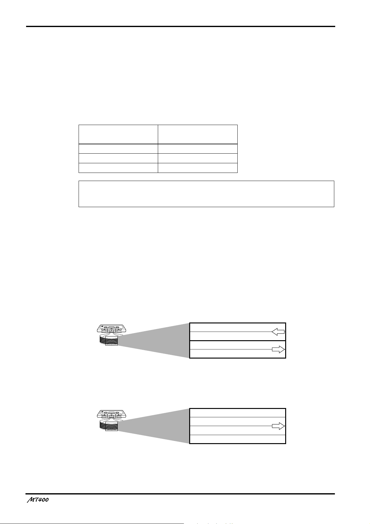
MT400 Recording Format
A normal cassette recorder uses only two tracks (i.e., left and right stereo channels) for each
side (A and B). The transport direction of the A side is opposite that of the B side. The MT400
uses only one side of the cassette, and records and plays up to four tracks simultaneously or
one at a time. Therefore, tapes with all four tracks recorded on the MT400 cannot be played
on normal cassette players. If you try to play back a tape recorded with normal cassette
recorders on the MT400, you will hear Tracks 3 and 4 play backwards.
Normal cassette recorder tracks
MT400 tracks
The tape speed of normal cassette recorders is 4.8 cm/second. On the other hand, the MT400
uses 9.5 cm/second as its standard speed to achieve high-quality sound.
—Owner’s Manual
Side B (left channel)
Side B (right channel)
Side A (right channel)
Side A (left channel)
Track 1
Track 2
Track 3
Track 4
transport
direction
transport
direction
transport
direction
Page 6

5
About dbx Noise Reduction
The MT400 uses the dbx noise reduction system to reduce tape hiss and keep your recordings
clean and crisp. For the best performance, it is recommended that you use the dbx noise
reduction for all your recordings. You should always use the dbx noise reduction system to
correctly play back tapes that were recorded with the dbx system on.
Glossary
This section describes basic terminology used in this manual.
■
Input channel
A path (channel) for audio signal between a mixer input jack and the bus (see below). Signal
input at an input jack is adjusted for the volume level and tonal quality here before being sent
to the bus.
■
Track
The MT400 can record four individual sound sources simultaneously on the four sections of a
cassette tape. This does not mean that the tape is cut into four pieces. The tape forms four
magnetic bands along the length of the tape. Each magnetic recording band is called a “track”.
The MT400 can use up to four tracks (Tracks 1–4).
■
Bus
A path where multiple audio signals are mixed into one signal. The MT400 offers the
following buses that can be used depending on the purpose.
Stereo L/R bus — This bus is used to create a stereo signal. Stereo bus signal is output
from the STEREO OUT L/R jacks. You can record stereo L bus signal to both Track 1
and 3 of the recorder section, and stereo R bus signal to both Track 2 and 4. To monitor
stereo bus signals, use the MONITOR OUT L/R jacks. You can also monitor them via
headphones.
Cue bus — This bus is used to create a monaural signal for monitoring, which is
output from the MONITOR OUT L/R jacks. You can also monitor the signal via
headphones.
AUX 1 and 2 buses — These buses are used to send out signals to connected effects
processors from the AUX SEND 1 and 2 jacks in monaural. You can monitor the signals
via headphones.
■
Overdubbing
Overdubbing is a technique used to record new sounds to empty tracks while listening to the
sounds already recorded on other tracks.
■
Ping-pong recording
Ping-pong recording is a technique used to free up tracks by mixing one or two existing tracks
to an unused track.
■
Mixdown
Mixdown is a technique used to mix the sounds into a balanced stereo mix and record it to a
stereo master recorder. It is also called “tracking down”.
—Owner’s Manual
Page 7
6
.
Touring the MT400
This section takes you on a tour of the MT400, identifying the various parts to familiarize you
with your new recorder.
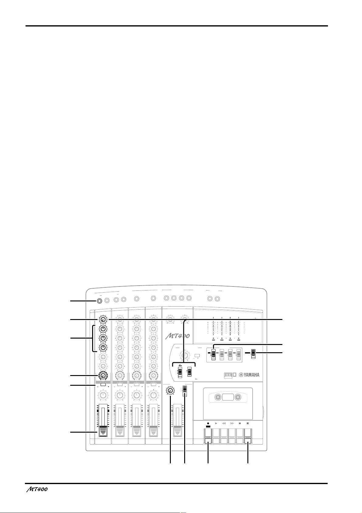
Input Channels
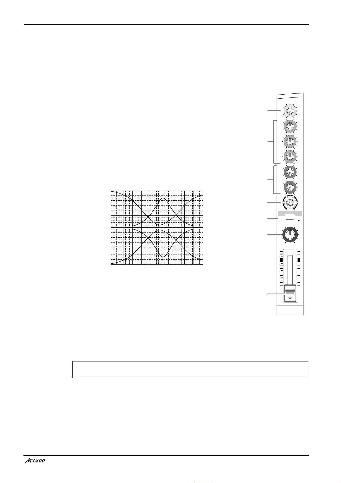
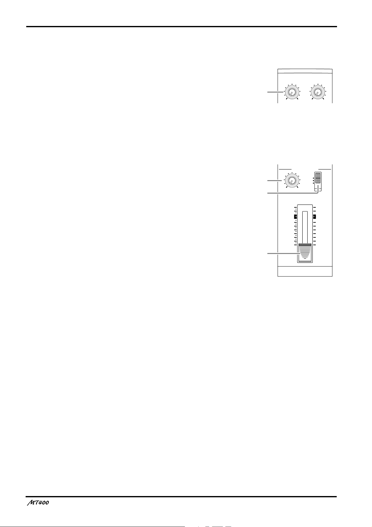
A
GAIN control
This rotary control adjusts the sensitivity of the MIC/LINE
INPUT jack
so that both microphone and line-level (such
d
as a synthesizer) signals can be handled with ease.
B
EQ control
These rotary controls are used to adjust a tonal quality of the
high, middle, and low frequency bands independently. They
boost (amplify) and cut (attenuate) the corresponding basic
frequency in the range of
±
12 dB. A flat setting (i.e., no boost
or cut) can be set quickly using the control’s center detentes.
15
10
5
0
–5
Response (dB)
–10
–15
50
Frequency (Hz)
10k 20k1k10020
5k2k500200
HIGH: Basic frequency 12 kHz (shelving type)
MID: Basic frequency 1 kHz (peaking type)
LOW: Basic frequency 80 Hz (shelving type)
1
2
3
4
5
6
7
GAIN
LINE MIC
HIGH
–12 +12
MID
–12 +12
LOW
–12 +12
AUX
1
010
AUX
2
010
MIX CUE
010
MIC/LINE
to L
TAPE
PAN
10
9
8
7
6
5
4
3
2
1
0
TAPE
MIC/
LINE
INPUT-FLIP
LR
1
C
AUX controls
These rotary controls are used to send the input channel (1–4) signal to the AUX SEND 1 and
2 outputs. They are commonly used to adjust the level of signal sent to external effects
processors.
Note: The AUX controls handle post-fader signals (signals that have passed through the
faders
CUE control
D
This control is used to adjust the level of Track (1–4) input signal and playback signal that will
be sent to the cue bus. The CUE bus signals are output from the PHONES jack or the
MONITOR OUT jack for monitoring.The CUE signal source depends on the [INPUT-FLIP]
switch
—Owner’s Manual
7
). If the faders are lowered all the way, the AUX control settings will not be effective.
5
Page 8
INPUT-FLIP
TAPE
MIC/
LINE
GAIN
HIGH
LINE MIC
–12 +12
MID
–12 +12
LOW
–12 +12
MIX CUE
010
INPUT-FLIP
TAPE
MIC/
LINE
GAIN
HIGH
LINE MIC
–12 +12
MID
–12 +12
LOW
–12 +12
MIX CUE
010
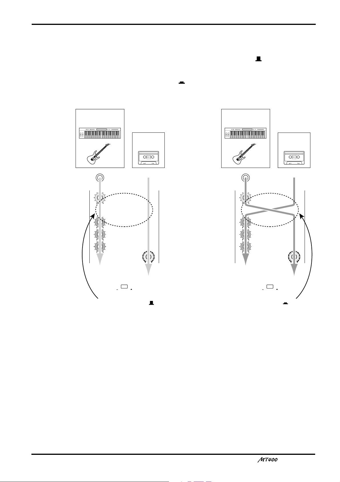
To CUE bus To ST bus
To ST bus
and tape
To ST bus
and tape
MT400 tape
signal
Musical instrument
signal input from
MIC/LINE INPUT jack
Musical instrument
signal input from
MIC/LINE INPUT jack
MT400 tape
signal
When INPUT-FLIP
switch is MIC/LINE ( )
When INPUT-FLIP
switch is TAPE ( )
E
INPUT-FLIP switch
This switch is used to select the destination of the signal input from the MIC/LINE INPUT
jacks and the tape signal. With the switch in the MIC/LINE position ( ), the MIC/LINE
input signal is fed to the ST bus via the input channel and the tape signal is fed to the CUE
bus.
With the switch in the TAPE position ( ), the MIC/LINE input 1, 3 (2, 4) signal is fed to the
ST L (ST R) bus and the tape signal is fed to the ST bus via the input channel.
7
F
PAN control
This rotary control is used to adjust the stereo position (left or right) of input channel signal
that will be sent to the Stereo bus. For recording via the Stereo bus (See page 22), turn this
control all the way to the left to assign the signal to odd tracks (1, 3), and all the way to the
right to assign the signal to even tracks (2, 4). For mixdown you can use it to pan the playback
signal in the stereo mix.
Fader
G
For recording ([INPUT-FLIP] switch: MIC/LINE), use the fader to adjust the level of the
input channel signal that is recorded to a track. For mixdown ([INPUT-FLIP] switch: TAPE),
use it to adjust the playback level of each track. Unity gain is obtained when the fader is
positioned about the 7–8 mark.
Unity gain : The condition where the output signal and input signal are at the same level,
with signal-to-noise ratio and distortion set to optimum.
—Owner’s Manual
Page 9
8
Stereo Inputs
LEVEL controls
H
These rotary controls are used to adjust the level of the
stereo input signals that are input at the STEREO
INPUT jacks 5 and 6 or 7 and 8. These signals are
usually sent to the Stereo bus for mixing with Input
Channel 1–4 signals and tape signals.
Monitor/Master Section
MONITOR LEVEL control
I
This rotary control adjusts the level of the monitor
h
m
and
.
signal that is sent to the MONITOR OUT
PHONES
J
Monitor select switch
h
jacks.
This switch is used to select the signal source for the
MONITOR OUT
STEREO
... This position selects the Stereo bus and
and PHONES
m
allows you to monitor the STEREO
OUT signal.
ST+CUE
.... This position selects the Stereo bus and
the CUE bus as the monitor source.
CUE
........... This position selects the CUE bus as the
monitor source.
LEVEL
5L–6R
LEVEL
7L–8R
8
010
MONITOR/PHONES
STEREO
ST+CUE
CUE
9
010
LEVEL
MIN MAX
J
STEREO
10
9
8
7
6
5
4
3
2
1
0
K
K
STEREO fader
Use this fader to adjust the level of the stereo signal
that is sent to the STEREO OUT jacks. Unity gain is
obtained when the fader is positioned about the 7–8
mark.
Unity gain : See
7
Fader.
—Owner’s Manual
Page 10
Recorder Section
4TR4
STEREO
METER SELECTREC SELECT
ZERO STOP
PITCH
NOISE REDUCTION SYSTEM
TAPE SPEED CONTROL
OFF
R
3
OFF
L
2
OFF
R
1
OFF
L
ON
OFF
ON
OFF
SYNC
4.8/ 9.5
– +
ONLM
QP
R
S
T
9
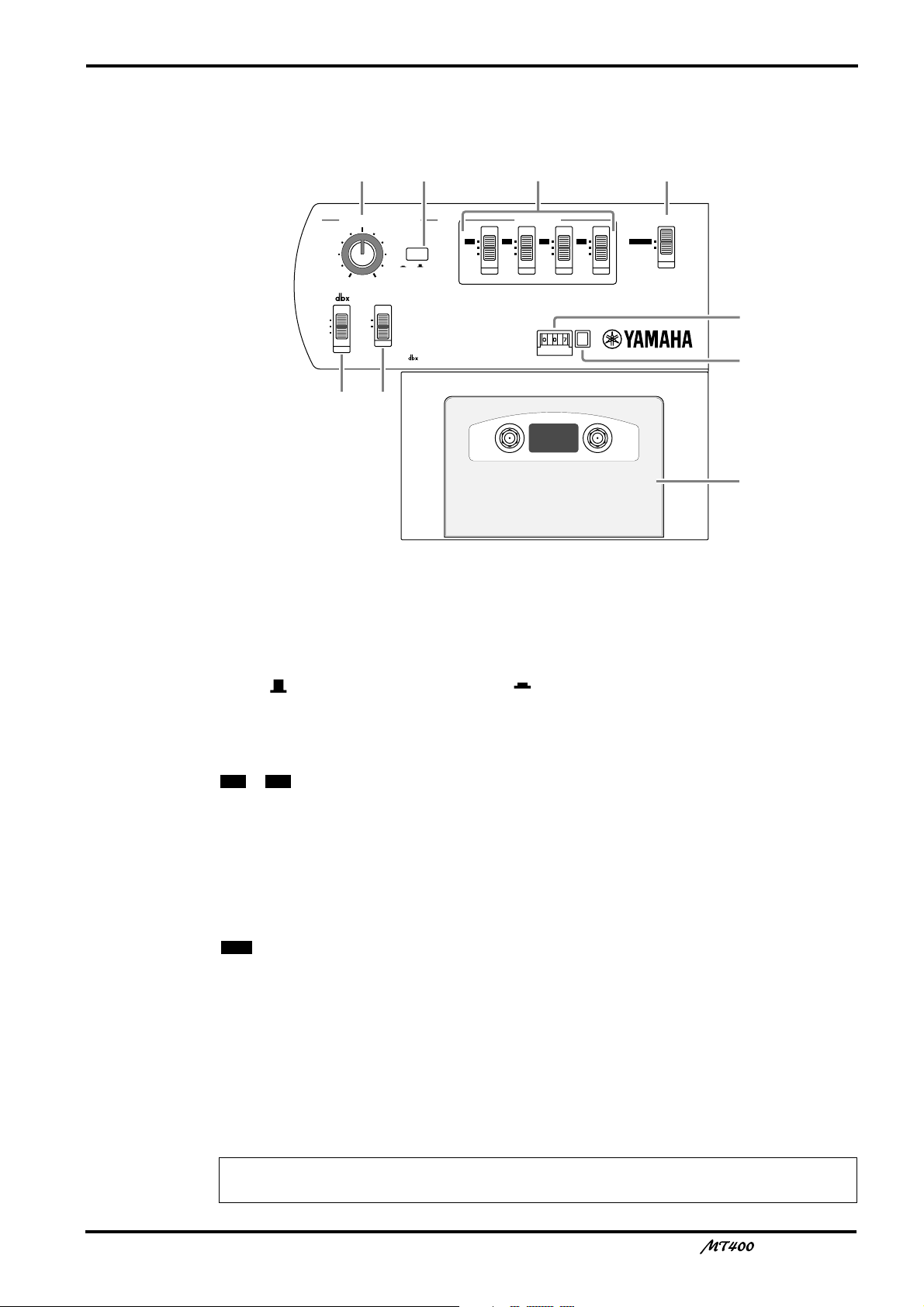
PITCH control
L
This rotary control adjusts the tape speed in the range of
M
Tape speed switch
±
10%.
This switch is used to select 4.8 cm/second or 9.5 cm/second for the tape speed. Set the switch
to 9.5 ( ) for normal recording, and 4.8 ( ) for playback of a tape recorded with a normal
cassette tape recorder.
N
REC SELECT switches
These switches are used to select recording sources for tracks.
– ...Input channel (1–4) signals are routed directly to the corresponding tracks for
1 4
recording (direct recording).
OFF
.............The corresponding tracks are disabled for recording.
L/R
..............The corresponding tracks are ready for recording and receive L channel (Tracks 1
and 3) or R channel (Tracks 2 and 4) signals.
O
METER SELECT switch
This switch selects the signal level to be displayed on the level meters
............The level meters display the track input signal levels during recording and the
4TR
track output signal levels during playback.
STEREO
....The level meters display the Stereo bus signal levels (signal output from the
a
.
STEREO OUT jacks).
dbx switch
P
Use this switch to turn on and off the dbx noise reduction system.
ON...............The dbx noise reduction system is turned on for all tracks.
OFF.............The dbx noise reduction system is turned off for all tracks.
SYNC .........The dbx noise reduction system is turned off only for Track 4.
Note: The SYNC setting is used for a special application in which Track 4 is used for
synchronization. See page 41 for more information.
—Owner’s Manual
Page 11
10
Q ZERO STOP switch
Use this switch to turn on and off the Zero Stop function. With this switch set to on (ON), the
tape rewind automatically stops when the tape counter returns to just before “000”.
R Tape counter
This 3-digit tape counter indicates the tape position.
S Counter reset button
This button resets the tape counter value to “000”.
T Cassette compartment
Insert a cassette tape here.
Transport Section
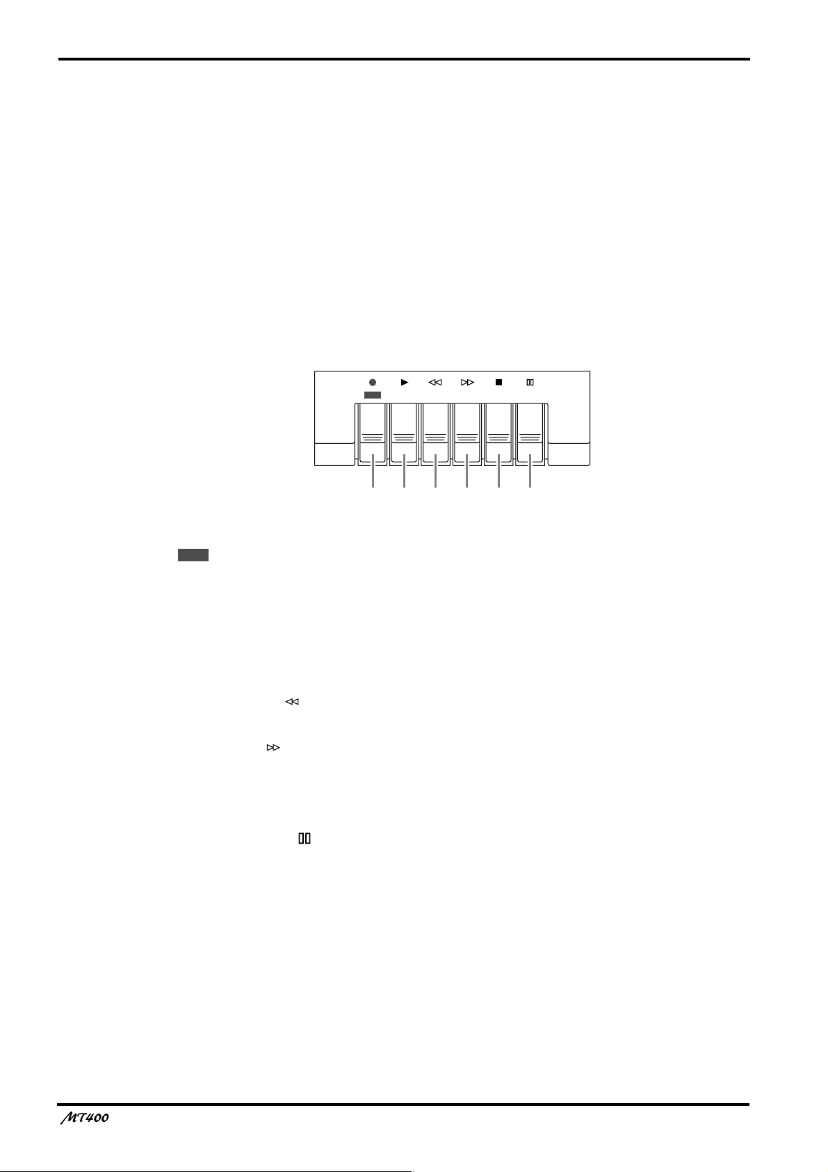
REC PLAY REW FF STOP PAUSE
UVWXYZ
REC
U button (●)
Pressing this button turns the PLAY button V on and starts recording on the currently
available tracks. When you press this button during playback, recording starts from the point
you press the button. This button is disabled if a tape is not set or write-protect tubs on the
tape are broken.
V PLAY button (®®
Use this button to start playback of the tracks.
®®
)
W REW button ( )
Use this button to rewind the tape.
X FF button ( )
Use this button to fast forward the tape.
Y STOP button (■)
Use this button to stop the tape transport.
Z PAUSE button ( )
Use this button to pause recording or playback. Pressing this button to stop recording or
playback and pressing it again will resume recording or playback.
—Owner’s Manual
Page 12
Meter Section
4
+6
+3
0
–5
–10
+6
+3
0
–5
–10
POWER
321
RL
REC
a
b
c
A
U
X
S
E
N
D
STEREO INPUT
M
IC
/L
IN
E
IN
P
U
T
IN
S
E
R
T
I/O
IN
S
E
R
T
I/O
1
2
1
2
3
4
5
L 6R 8R7L
ge
d
f
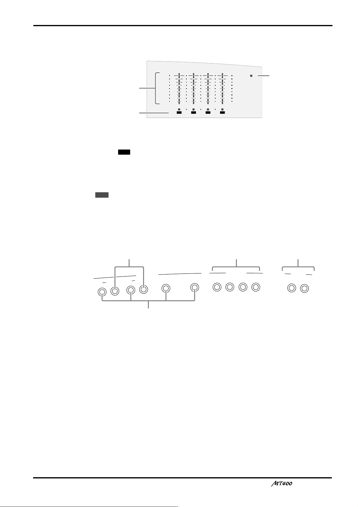
a Level meters
These meters show the signal levels from –10 dB to +6 dB. When the METER SELECT switch
O is set to “ ”, they show the track signal levels during recording and playback. When the
METER SELECT switch is set to “STEREO”, they show the STEREO OUT signal levels.
b REC SELECT indicator
These indicators show which tracks are selected for recording. They flash when you select
recording sources by the REC SELECT switches
REC
the button to start recording.
4TR
N, and light up continuously when you press
11
c POWER indicator
This indicator lights up when you turn on the power to the unit.
Input/Output Section
d MIC/LINE INPUTs 1–4
Use these 1/4" TRS phone jacks to connect microphones and electronic musical instruments
such as a synthesizer to the MT400.
e INSERT I/O
Use these TRS phone jacks to output, then input channels 1 and 2 signals. Typically, signal
processors, such as compressors, limiters, and noise gates are connected to these jacks. Signals
output from the mixer section are processed on the effects processor and returned to the
mixer via these jacks. (See page 28)
f STEREO INPUTs
Use these 1/4" phone jacks to connect line-level sound sources that have stereo outputs, such
as a synthesizer and a CD player. They can also be used to return the processed stereo signals
from external effects processors, such as a reverb unit. (See page 29)
g AUX SEND
Use these 1/4" phone jacks to output the channel signals adjusted by the AUX controls 3. You
can use these as effect sends by connecting to the effects processors’ inputs. (See page 29)
—Owner’s Manual
Page 13
12
Front Panel
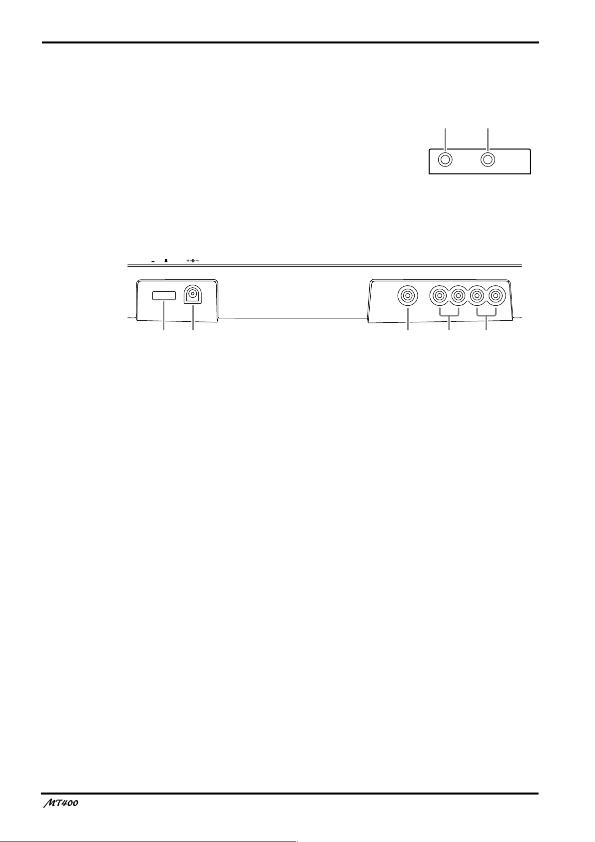
h PHONES
A pair of stereo headphones can be connected here for
monitoring. The headphone signal is the same as the
MONITOR OUT signal.
hi
i PUNCH I/O
An optional footswitch, such as the Yamaha FC5, can be
connected here for foot-controlled punch in/out.
Rear Panel
DC 12VPOWER
ON/ OFF
j POWER ON/OFF switch
Use this switch to turn on and off the MT400.
k DC 12V
Connect the AC adapter here.
Use a 12 V AC adapter of at least 650 mA.
PHONES PUNCH I/O
SYNC OUT MONITOR OUT STEREO OUT
lkj
RLRL
nm
l SYNC OUT
Use this phono jack to individually output FSK and SMPTE synchronization signals recorded
on the sync track (Track 4).
m MONITOR OUTs
Use these phono jacks to send the monitor signals. Connect your hi-fi system or powered
speakers.
n STEREO OUTs
Use these phono jacks to output Stereo bus signal adjusted by the STEREO fader. Connect
them to your master recorder’s stereo inputs for mixdown.
—Owner’s Manual
Page 14
The First Session
4
4TR4
STEREO
+6
+3
0
–5
–10
+6
+3
0
–5
–10
POWER
A
U
X
S
E
N
D
STEREO INPUT
METER SELECTREC SELECT
MONITOR/PHONES
ZERO STOP
PITCH
NOISE REDUCTION SYSTEM
TAPE SPEED CONTROL
321
RL
REC
REC PLAY REW FF STOP PAUSE
OFF
R
3
OFF
L
2
OFF
R
1
OFF
L
ON
OFFONOFF
SYNC
STEREO
ST+CUE
CUE
MULTITRACK CASSETTE RECORDER
M
IC
/L
IN
E
IN
P
U
T
IN
S
E
R
T
I/O
IN
S
E
R
T
I/O
1
2
1
2
3
4
5
L 6R 8R7L
4.8/ 9.5
– +
LEVEL
STEREO
7
L–8R
010
LEVEL
5L–6R
010
LEVEL
MIN MAX
10
9
8
7
6
5
4
3
2
1
0
GAIN
HIGH
10
9
8
7
6
5
4
3
2
1
0
LINE MIC
–12 +12
MID
–12 +12
LOW
–12 +12
AUX
1
010
AUX
2
MIX CUE
MIX CUE MIX CUE MIX CUE
010
010
PAN
INPUT-FLIP
TAPE
TAPE
MIC/
LINE
MIC/LINE
to L
LR
1
GAIN
HIGH
10
9
8
7
6
5
4
3
2
1
0
LINE MIC
–12 +12
MID
–12 +12
LOW
–12 +12
AUX
1
010
AUX
2
010
010
PAN
INPUT-FLIP
TAPE
TAPE
MIC/
LINE
MIC/LINE
to R
LR
2
GAIN
HIGH
10
9
8
7
6
5
4
3
2
1
0
LINE MIC
–12 +12
MID
–12 +12
LOW
–12 +12
AUX
1
010
AUX
2
010
010
PAN
INPUT-FLIP
TAPE
TAPE
MIC/
LINE
MIC/LINE
to L
LR
3
GAIN
HIGH
10
9
8
7
6
5
4
3
2
1
0
LINE MIC
–12 +12
MID
–12 +12
LOW
–12 +12
AUX
1
010
AUX
2
010
010
PAN
INPUT-FLIP
TAPE
TAPE
MIC/
LINE
MIC/LINE
to R
LR
4
PHONES PUNCH I/O
SYNC OUT MONITOR OUT STEREO OUT
RLRL
DC 12VPOWER
ON/ OFF
YAMAHA YAMAHA
YAMAHA
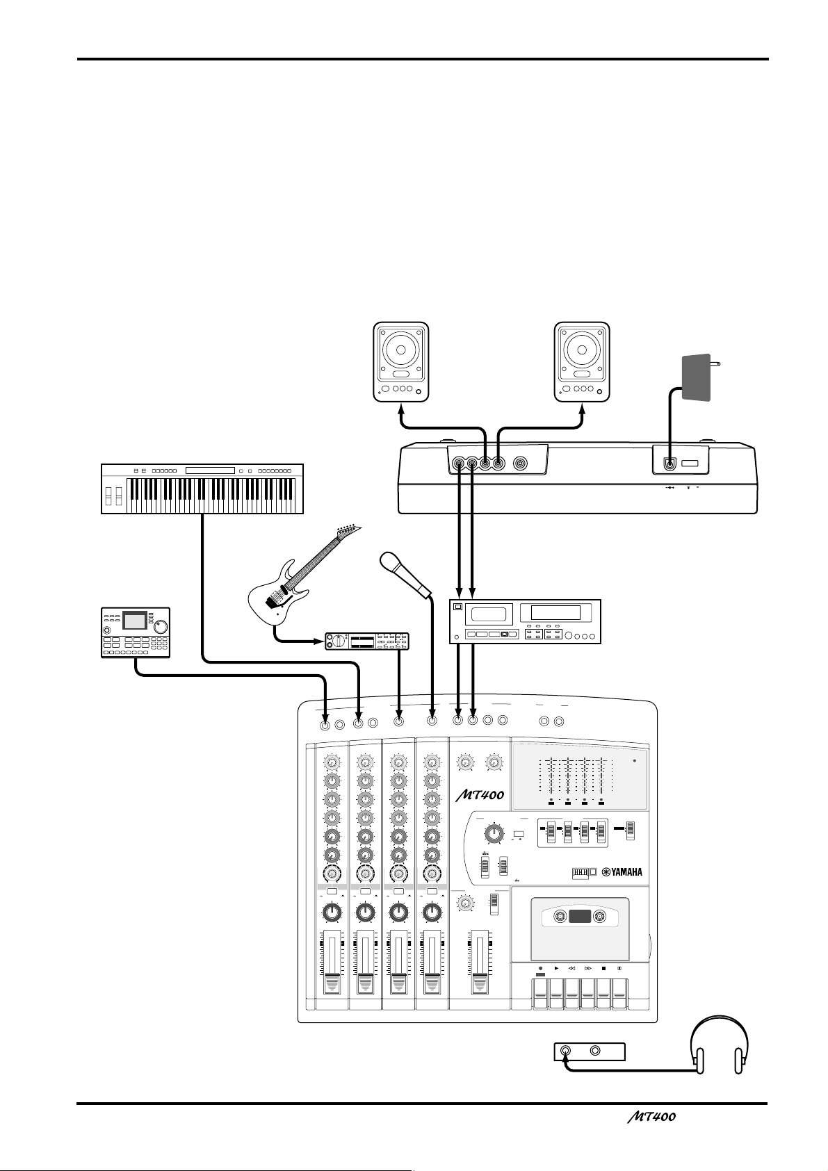
AC adapter
Master recorder
Powered speakers /
Hi-fi stereo system
Headphones
Rhythm machine
Microphone
Guitar
Keyboard
Guitar effects
processor
This chapter explains how to record four tracks individually and mix your first MT400 session
onto a master recorder.
Preparation
Quick-Start System
13
—Owner’s Manual
Page 15
14
Turning On the MT400
1. Make sure that the plug of the supplied AC
adapter is securely connected to the DC12V
jack on the rear of the MT400.
2. Plug the other end of the AC adapter into a
suitable AC outlet.
3. Press the POWER switch on the rear panel of
the MT400. The POWER indicator in the
meter section lights up.
Loading a Cassette Tape
Before loading a cassette tape, make sure the tape is
not slack inside the cassette. Also, make sure the write-
Recording the First Track
The MT400 allows signals input at MIC/LINE INPUT 1–4 to be directly recorded on Tracks
1–4 respectively (this is called “direct recording”). Connecting a sound source to MIC/LINE
INPUT 1 will automatically select Track 1 for recording, and connecting another sound
source to MIC/LINE INPUT 3 will automatically select Track 3 for recording. This is
convenient for recording one sound source at a time.
This section explains how to record the first sound source in Track 1.
protect tabs are not broken. If they are broken, you
cannot record on the tape.
1. Open the cassette compartment cover.
2. Load the cassette into the compartment with
the A side facing up.
3. Close the cassette compartment cover.
If it is a new tape, fast forward and rewind it once to
prevent binding, which may occur due to the tape
being tightly wound during manufacturing.
4. Press the [PLAY] button to start playback, and
stop after about 20 seconds.
It is best not to use the first and last 20 seconds of a
tape, as the splice between the leader and tape can
cause distortion.
Preparation Before Recording
T
U
P
IN
E
IN
/L
IC
1
7
C
A
2
8
M
INSERT I/O
2
INSERT I/O
1
1
GAIN
GAIN
LINE MIC
LINE MIC
HIGH
HIGH
–12 +12
MID
LOW
AUX
1
AUX
2
MIX CUE
PAN
10
9
8
7
6
5
4
3
2
1
0
–12 +12
MID
–12 +12
–12 +12
LOW
–12 +12
–12 +12
AUX
1
010
010
AUX
2
010
010
MIX CUE MIX CUE MIX CUE
010
010
TAPE
MIC/LINE
MIC/LINE
to L
to R
MIC/
TAPE
TAPE
LINE
INPUT-FLIP
INPUT-FLIP
PAN
LR
LR
10
9
8
7
6
5
4
3
2
1
0
2
TAPE
MIC/
LINE
GAIN
LINE MIC
HIGH
–12 +12
MID
–12 +12
LOW
–12 +12
AUX
1
010
AUX
2
010
010
MIC/LINE
to L
TAPE
INPUT-FLIP
PAN
LR
10
9
8
7
6
5
4
3
2
1
0
4
3
3
GAIN
LINE MIC
HIGH
–12 +12
MID
–12 +12
LOW
–12 +12
AUX
1
010
AUX
2
010
010
TAPE
MIC/LINE
to R
MIC/
TAPE
LINE
INPUT-FLIP
PAN
LR
10
9
8
7
6
5
4
3
2
1
0
TAPE
MIC/
LINE
4
5
LEVEL
LEVEL
MIN MAX
STEREO INPUT
L 6R 8R7L
7
5L–6R
LEVEL
010
010
MULTITRACK CASSETTE RECORDER
TAPE SPEED CONTROL
PITCH
– +
SYNC
MONITOR/PHONES
STEREO
ST+CUE
CUE
STEREO
10
9
8
7
6
5
4
3
2
1
0
L–8R
ZERO STOP
ON
OFFONOFF
4.8/ 9.5
NOISE REDUCTION SYSTEM
A
U
X
S
E
N
D
1
2
+6
+3
0
–5
–10
REC
RL
L
REC
PLAY REW FF STOP PAUSE
+6
POWER
+3
0
–5
–10
4321
METER SELECTREC SELECT
431 4TR2
STEREO
OFFROFFLOFFROFF
9
3
4
—Owner’s Manual
B 0
6
5
Page 16

15
Selecting a recording track
Connect a sound source to MIC/LINE INPUT
1
1.
It is best to record a rhythm instrument, such as a
rhythm machine, drums, or a rhythm guitar, first.
2 Set the [INPUT-FLIP] switch on Input Channel
1 to “MIC/LINE ( )”.
This switch setting sends the MIC/LINE INPUT signal
to the corresponding input channel.
3 Set Track 1 [REC SELECT] switch to “ ”.
The [REC SELECT] switches enable you to select a
recording source for each track. With Track 1 [REC
SELECT] switch set to “ ”, Track 1 is ready for
recording, and the signal on Input Channel 1 is sent to
Track 1. Also, the Track 1 REC SELECT indicator
flashes.
1
1
Checking the recording level
It is essential to set an appropriate recording level to
achieve the best sound quality. Be sure to adjust the
recording level before each recording session.
4 Set the [METER SELECT] switch to “ ”.
The [METER SELECT] switch is used to select a signal
monitored on the level meters. With the “ ”
setting, you can monitor the input level of the
recording source on the recording/recording-pause
tracks, and the tape signal level on the playback tracks.
4TR
4TR
Monitoring a track recording signal
Set the monitor select switch to “CUE”.
0
The monitor select switch enables you to select a
monitoring source. The “CUE” setting sends the CUE
bus signal (monaural) to the connected audio system
or headphones for monitoring via the PHONES and
MONITOR OUT jacks.
A Set the CUE control on Input Channel 1
midway around noon.
The CUE controls on Input Channels 1–4 adjust the
level of the signals (recording source signals on the
recording/recording-pause tracks, and tape signals on
the playback tracks) that are sent from Tracks 1–4 to
the CUE bus.
B While monitoring the signal through the
headphones or the audio system, use the
MONITOR LEVEL control to adjust the
monitoring sound to the desired level.
C If necessary, use the EQ controls to adjust
tonal quality.
Adjusting the EQ controls will change the recording
level as well. After you adjust the EQ controls, adjust
the GAIN control for the recording level again, if
necessary.
5 Press the [PAUSE] button.
6 Press the button.
The Track 1 REC SELECT indicator stops flashing and
lights up continuously, and the MT400 enters
recording pause mode. Since you pressed the [PAUSE]
button, recording does not start.
REC
7 Turn the GAIN control on Input Channel 1 all
the way to LINE.
8 Raise the fader on Input Channel 1 up to
between marks 7 and 8.
9 Play the sound source, and turn the GAIN
control while checking the level meter to
adjust the recording level. Set the [dbx]
switch and the [ZERO STOP] switch to “ON”.
Adjust the GAIN control so that the +3 segment of the
level meter lights up momentarily on the loudest
sounds if dbx has been turned off, and the +6 segment
of the level meter lights up momentarily if dbx has
been turned on.
If the recording level is very high even when the GAIN
control is turned all the way to LINE, lower the output
level on the sound source.
—Owner’s Manual
Page 17

16
The First Take
IC
M
INSERT I/O
2
INSERT I/O
1
1
GAIN
GAIN
LINE MIC
LINE MIC
HIGH
HIGH
–12 +12
MID
LOW
AUX
1
AUX
2
MIX CUE
MIC/LINE
to L
TAPE
PAN
10
9
8
7
6
5
4
3
2
1
0
–12 +12
MID
–12 +12
–12 +12
LOW
–12 +12
–12 +12
AUX
1
010
010
AUX
2
010
010
MIX CUE MIX CUE MIX CUE
010
010
TAPE
MIC/LINE
to R
MIC/
TAPE
LINE
INPUT-FLIP
INPUT-FLIP
PAN
LR
LR
10
9
8
7
6
5
4
3
2
1
0
IN
/L
TAPE
MIC/
LINE
IN
E
2
T
U
P
GAIN
LINE MIC
HIGH
–12 +12
MID
–12 +12
LOW
–12 +12
AUX
1
010
AUX
2
010
010
MIC/LINE
to L
TAPE
INPUT-FLIP
PAN
LR
10
9
8
7
6
5
4
3
2
1
0
4
TAPE
MIC/
LINE
5
LEVEL
010
LEVEL
MIN MAX
STEREO INPUT
L 6R 8R7L
L–8R
5L–6R
7
LEVEL
010
MULTITRACK CASSETTE RECORDER
TAPE SPEED CONTROL
PITCH
– +
ZERO STOP
ON
OFFONOFF
SYNC
MONITOR/PHONES
STEREO
ST+CUE
CUE
STEREO
10
9
8
7
6
5
4
3
2
1
0
4
3
3
GAIN
LINE MIC
HIGH
–12 +12
MID
–12 +12
LOW
–12 +12
AUX
1
010
AUX
2
010
010
TAPE
MIC/LINE
to R
MIC/
TAPE
LINE
INPUT-FLIP
PAN
LR
10
9
8
7
6
5
4
3
2
1
0
4.8/ 9.5
NOISE REDUCTION SYSTEM
A
U
X
S
E
N
D
1
2
+6
+3
0
–5
–10
REC
RL
L
REC
PLAY REW FF STOP PAUSE
+6
POWER
+3
0
–5
–10
4321
METER SELECTREC SELECT
431 4TR2
STEREO
OFFROFFLOFFROFF
6
1
Starting recording
Press the counter reset button to set the tape
1
counter to “000”.
2 Press the [PAUSE] button to cancel pause
mode.
This starts recording. Play the sound source for
recording.
3 Press the [STOP] button to stop recording.
The Track 1 REC SELECT indicator flashes.
2
354
Listening to the first track
Press the [REW] button to rewind the tape.
4
If the [ZERO STOP] switch is set to ON, the tape
rewinds until the tape counter shows “000” and stops
automatically.
5 Press the [PLAY] button to start playback.
If the [INPUT-FLIP] switch on Input Channel 1 is set
to “MIC/LINE ( )”, you can monitor the Track 1
playback sound (sent via the CUE bus) through the
PHONES or MONITOR OUT jack.
To record again, rewind the tape to the beginning and
press the button. If you wish to re-record part
REC
of the recording, perform punch in/out recording. See
page 34 for more information.
6 If you are satisfied with your first take on
Track 1, set the [REC SELECT] switch on Track
1 to “OFF”.
The Track 1 REC SELECT indicator turns off.
—Owner’s Manual
Page 18

17
Note: Be sure to turn the [REC SELECT] switch on Track 1 to “OFF”. Otherwise, recording
on Track 1 will be erased when you record the next track.
MIC/LINE INPUT 1
1
GAIN
LINE MIC
HIGH
–12 +12
MID
–12 +12
LOW
–12 +12
AUX
1
010
AUX
2
010
MIX CUE
010
MIC/LINE
to L
TAPE
INPUT-FLIP
PAN
CUE bus (monaural)
TAPE
MIC/
LINE
PHONES
MONITOR OUT
LR
10
9
8
7
6
5
4
3
2
1
0
Track 1
Track 2
Track 3
Track 4
Signal flow during track recording
—Owner’s Manual
Page 19

18
Overdubbing
You may record a different sound source to another track while listening to the sound
recorded on Track 1. The basic procedure for overdubbing is the same as the first take.
1
5
6
2
IC
M
INSERT I/O
2
INSERT I/O
1
1
GAIN
GAIN
LINE MIC
LINE MIC
HIGH
HIGH
–12 +12
MID
LOW
AUX
1
AUX
2
MIX CUE
PAN
10
9
8
7
6
5
4
3
2
1
0
–12 +12
MID
–12 +12
–12 +12
LOW
–12 +12
–12 +12
AUX
1
010
010
AUX
2
010
010
MIX CUE MIX CUE MIX CUE
010
010
TAPE
MIC/LINE
MIC/LINE
to L
to R
MIC/
TAPE
TAPE
LINE
INPUT-FLIP
INPUT-FLIP
PAN
LR
LR
10
9
8
7
6
5
4
3
2
1
0
/L
TAPE
LINE
IN
E
IN
2
MIC/
T
U
P
GAIN
LINE MIC
HIGH
–12 +12
MID
–12 +12
LOW
–12 +12
AUX
1
010
AUX
2
010
010
MIC/LINE
to L
TAPE
INPUT-FLIP
PAN
LR
10
9
8
7
6
5
4
3
2
1
0
TAPE
MIC/
LINE
4
LEVEL
LEVEL
MIN MAX
STEREO INPUT
L 6R 8R7L
5
5L–6R
7
LEVEL
010
010
MULTITRACK CASSETTE RECORDER
TAPE SPEED CONTROL
PITCH
– +
SYNC
MONITOR/PHONES
STEREO
ST+CUE
CUE
STEREO
10
9
8
7
6
5
4
3
2
1
0
L–8R
ZERO STOP
ON
OFFONOFF
4
3
3
GAIN
LINE MIC
HIGH
–12 +12
MID
–12 +12
LOW
–12 +12
AUX
1
010
AUX
2
010
010
TAPE
MIC/LINE
to R
MIC/
TAPE
LINE
INPUT-FLIP
PAN
LR
10
9
8
7
6
5
4
3
2
1
0
4.8/ 9.5
NOISE REDUCTION SYSTEM
A
U
X
S
E
N
D
1
2
+6
+3
0
–5
–10
REC
RL
L
REC
PLAY REW FF STOP PAUSE
+6
POWER
+3
0
–5
–10
4321
METER SELECTREC SELECT
431 4TR2
STEREO
OFFROFFLOFFROFF
3,9
Selecting a recording track
Connect a sound source to MIC/LINE INPUT
1
2.
2 Set the [INPUT-FLIP] switch on Input Channel
2 to “MIC/LINE ( )”.
Leave the [INPUT-FLIP] switch on Input Channel 1
to “MIC/LINE ( )”.
3 Set Track 2 [REC SELECT] switch to “ ”.
2
The Track 2 REC SELECT indicator flashes and Track
1 is ready for recording.
Note: Make sure that the [REC SELECT] switch on
Track 1 is set to “OFF”.
4 Press the [PAUSE] button, then the
REC
button.
5 While checking the level meter, use the GAIN
control and fader on Input Channel 2 to set
the optimum recording level.
784
Monitoring the recording source and tape
playback sound simultaneously
While playing the recording source, turn up
6
the CUE control on Input Channel 2.
CUE control 2 adjusts the monitoring level of the
signal recorded on Track 2. Adjust to a desired level
while listening to the sound through headphones or
monitor speakers. When you start recording, Track 1
playback sound and Track 2 recording source will be
mixed into a monaural signal and sent to the CUE bus
for monitoring.
—Owner’s Manual
Page 20

19
Start recording
Press the [PAUSE] button to start recording.
7
Press the [STOP] button to stop recording.
1
GAIN
LINE MIC
HIGH
–12 +12
MID
–12 +12
LOW
–12 +12
AUX
1
010
AUX
2
010
MIX CUE
010
TAPE
MIC/LINE
to L
MIC/
TAPE
LINE
INPUT-FLIP
PAN
LR
10
9
8
7
6
5
4
3
2
1
0
MIC/LINE INPUT 1
GAIN
LINE MIC
HIGH
–12 +12
MID
–12 +12
LOW
–12 +12
AUX
1
010
AUX
2
010
MIX CUE
010
TAPE
MIC/LINE
to R
MIC/
TAPE
LINE
INPUT-FLIP
PAN
LR
10
9
8
7
6
5
4
3
2
1
0
Listening to the recording
Press the [REW] button to rewind the tape to
8
the beginning and press the [PLAY] button to
start playback.
9 If you are satisfied with your recording, set
the [REC SELECT] switch on Track 2 to “OFF”.
Repeat this procedure until you have recorded all
tracks.
2
PHONES
CUE bus (monaural)
Track 1
Track 2
Track 3
Track 4
MONITOR OUT
Signal flow during overdubbing
—Owner’s Manual
Page 21

20
Mixdown
After you have recorded all tracks, you are ready to mix them into a stereo mix, which you will
record to a stereo master recorder.
0
7
2
ON/ OFF
/L
IC
M
INSERT I/O
2
INSERT I/O
1
1
GAIN
GAIN
LINE MIC
LINE MIC
HIGH
HIGH
–12 +12
MID
LOW
AUX
1
AUX
2
MIX CUE
MIC/LINE
to L
TAPE
PAN
10
9
8
7
6
5
4
3
2
1
0
–12 +12
MID
–12 +12
–12 +12
LOW
–12 +12
–12 +12
AUX
1
010
010
AUX
2
010
010
MIX CUE MIX CUE MIX CUE
010
010
TAPE
MIC/LINE
to R
MIC/
TAPE
LINE
INPUT-FLIP
INPUT-FLIP
PAN
LR
LR
10
9
8
7
6
5
4
3
2
1
0
E
IN
2
TAPE
MIC/
LINE
DC 12VPOWER
U
P
IN
GAIN
HIGH
MID
LOW
AUX
1
AUX
2
MIC/LINE
to L
TAPE
PAN
10
9
8
7
6
5
4
3
2
1
0
T
LINE MIC
–12 +12
–12 +12
–12 +12
3
3
010
010
010
TAPE
MIC/
LINE
INPUT-FLIP
LR
GAIN
LINE MIC
HIGH
–12 +12
MID
–12 +12
LOW
–12 +12
AUX
1
010
AUX
2
010
010
MIC/LINE
to R
TAPE
INPUT-FLIP
PAN
LR
10
9
8
7
6
5
4
3
2
1
0
4
TAPE
MIC/
LINE
4
LEVEL
LEVEL
MIN MAX
STEREO INPUT
L 6R 8R7L
5
7
5L–6R
LEVEL
010
010
MULTITRACK CASSETTE RECORDER
TAPE SPEED CONTROL
PITCH
– +
ON
OFF
SYNC
MONITOR/PHONES
STEREO
ST+CUE
CUE
STEREO
10
9
8
7
6
5
4
3
2
1
0
L–8R
ZERO STOP
ON
OFF
4.8/ 9.5
SYNC OUT MONITOR OUT STEREO OUT
RLRL
A
U
X
S
E
N
D
1
2
+6
+3
0
–5
–10
REC
RL
L
NOISE REDUCTION SYSTEM
REC
PLAY REW FF STOP PAUSE
11
+6
POWER
+3
0
–5
–10
4321
METER SELECTREC SELECT
431 4TR2
STEREO
OFFROFFLOFFROFF
4
3
Connecting a master recorder
Connect the STEREO OUT jacks on the rear
1
panel of the MT400 to the input jacks of a
master recorder, and connect the output
jacks of the master recorder to the STEREO
INPUT 5L/6R jacks on the top panel of the
MT400.
Sending the tape playback sound to the
input channels
Set the [INPUT-FLIP] switches on Input
2
Channels 1–4 to “TAPE ( )”.
When the [INPUT-FLIP] switches are set to “TAPE
( )”, the playback sound of the corresponding tracks
—Owner’s Manual
65
are sent to the input channels, where you can adjust
tonal quality with the EQ controls and stereo position
with the PAN control. The playback sound sent to
Input Channels 1–4 are routed to the STEREO bus for
stereo mix and output from the SETEREO OUT jacks.
3 Set the monitor select switch to “STEREO”.
The stereo bus is selected as a monitoring source, and
you can listen to the STEREO OUT signals via
headphones or an audio system connected to the
PHONES or MONITOR OUT jacks.
4 Set the [METER SELECT] switch to “STEREO”.
The level meters L and R on the left indicate the level
of the Stereo bus signal output from the STEREO
OUT jacks.
Page 22

21
5 Raise the STEREO fader to the 7–8 mark.
6 Press the [REW] button to rewind the tape,
and press the [PLAY] button to start playback.
7 While listening to the headphones or the
monitor speakers, adjust the faders, PAN
controls, and EQ controls on Input Channel
1–4.
First use the faders to adjust level balance between
tracks, so that the +3 segments of the level meters light
up momentarily at the loudest peaks. Use the STEREO
fader, if necessary, for fine adjustments. Then use the
PAN controls to set the stereo position. Finally, use the
EQ controls to adjust the tonal quality to refine your
music, and re-adjust the volume level, if necessary.
GAIN
1
GAIN
2
GAIN
Recording to a master recorder
Record the final mix to a stereo master recorder.
8 Start recording on the master recorder and
start playback from the top of the song on
the MT400.
9 When you finish mixdown, stop the MT400
and the master recorder.
0 Play the master recorder from the beginning
and turn the LEVEL control 5–6 for STEREO
INPUTs to listen to the mix.
To listen to the mix recorded on the master recorder,
you need to connect the output jacks of the master
recorder to STEREO INPUTs 5 and 6 of the MT400 to
monitor via the Stereo bus. To adjust the monitoring
level, use the LEVEL control 5–6 for STEREO INPUTs
and the STEREO fader.
Track 1
Track 2
Track 3
3
GAIN
4
Track 4
LINE MIC
HIGH
–12 +12
MID
–12 +12
LOW
–12 +12
AUX
1
010
AUX
2
010
MIX CUE
010
TAPE
MIC/LINE
to L
MIC/
TAPE
LINE
INPUT-FLIP
PAN
LR
10
9
8
7
6
5
4
3
2
1
0
LINE MIC
HIGH
–12 +12
MID
–12 +12
LOW
–12 +12
AUX
1
010
AUX
2
010
MIX CUE MIX CUE MIX CUE
010
TAPE
MIC/LINE
to R
MIC/
TAPE
LINE
INPUT-FLIP
PAN
LR
10
9
8
7
6
5
4
3
2
1
0
LINE MIC
HIGH
–12 +12
MID
–12 +12
LOW
–12 +12
AUX
1
010
AUX
2
010
010
MIC/LINE
to L
TAPE
INPUT-FLIP
PAN
LR
10
9
8
7
6
5
4
3
2
1
0
LINE MIC
HIGH
–12 +12
MID
–12 +12
LOW
–12 +12
AUX
1
010
AUX
2
010
TAPE
MIC/
LINE
010
MIC/LINE
to R
TAPE
INPUT-FLIP
PAN
LR
10
9
8
7
6
5
4
3
2
1
0
TAPE
LINE
PHONES
MONITOR OUT
STEREO OUT
MIC/
STEREO
10
9
8
7
6
5
4
3
2
1
0
Stereo bus L, R
Signal flow during mixdown
—Owner’s Manual
Page 23

22
Advanced Recording Techniques
This chapter introduces you to various advanced recording techniques using the MT400.
Simultaneous Multi-Channel Recording
In addition to recording four tracks individually as explained earlier, you may sometimes wish
to record multiple sound sources to a track or two. (For example, you may wish to record
drum, bass, and rhythm guitar sounds to two tracks in stereo.) To do this, you can mix input
channel signals into a stereo mix via the Stereo bus, and record the mix to two tracks. The
following procedure explains how to mix four sound sources connected to MIC/LINE
INPUTS 1–4 into stereo and record the mix to Tracks 1 and 2.
1
7
9
2
IC
M
ER
INS
2
INSERT I/O
1
1
GAIN
GAIN
LINE MIC
HIGH
MID
LOW
AUX
1
AUX
2
MIX CUE
PAN
10
9
8
7
6
5
4
3
2
1
0
LINE MIC
HIGH
–12 +12
–12 +12
MID
–12 +12
–12 +12
LOW
–12 +12
–12 +12
AUX
1
010
010
AUX
2
010
010
MIX CUE MIX CUE MIX CUE
010
010
TAPE
MIC/LINE
MIC/LINE
to L
to R
MIC/
TAPE
TAPE
LINE
INPUT-FLIP
INPUT-FLIP
PAN
LR
LR
10
9
8
7
6
5
4
3
2
1
0
/L
T I/O
TAPE
E
IN
2
MIC/
LINE
T
U
P
IN
GAIN
LINE MIC
HIGH
–12 +12
MID
–12 +12
LOW
–12 +12
AUX
1
AUX
2
MIC/LINE
to L
TAPE
INPUT-FLIP
PAN
LR
10
9
8
7
6
5
4
3
2
1
0
3
3
010
010
010
TAPE
MIC/
LINE
4
GAIN
LINE MIC
HIGH
–12 +12
MID
–12 +12
LOW
–12 +12
AUX
1
010
AUX
2
010
010
MIC/LINE
to R
TAPE
INPUT-FLIP
PAN
LR
10
9
8
7
6
5
4
3
2
1
0
TAPE
MIC/
LINE
4
LEVEL
LEVEL
MIN MAX
STEREO INPUT
L 6R 8R7L
5
5L–6R
LEVEL
010
010
MULTITRACK CASSETTE RECORDER
TAPE SPEED CONTROL
PITCH
– +
SYNC
MONITOR/PHONES
STEREO
ST+CUE
CUE
STEREO
10
9
8
7
6
5
4
3
2
1
0
7L–8R
ZERO STOP
ON
OFFONOFF
4.8/ 9.5
NOISE REDUCTION SYSTEM
A
U
X
S
E
N
D
1
2
+6
+3
0
–5
–10
REC
RL
L
REC
PLAY REW FF STOP PAUSE
+6
POWER
+3
0
–5
–10
4321
METER SELECTREC SELECT
431 4TR2
STEREO
OFFROFFLOFFROFF
3,B
4
8
6
1 Connect sound sources to MIC/LINE INPUTS
1–4.
You can also mix the sound of a line-level instrument,
such as a synthesizer, connected to STEREO INPUTS
5L/6R or 7L/8R.
2 Set the [INPUT–FLIP] switches on Input
Channels 1–4 to “MIC/LINE ( )”.
3 Set the [REC SELECT] switches on Tracks 1–2
to “L” and “R” respectively.
—Owner’s Manual
05 A
Tracks 1 and 2 REC SELECT indicators flash.
With the [INPUT-FLIP] switches set to “MIC/LINE
( )”, Input Channels 1–4 signals are sent to the
Stereo bus. Setting the [REC SELECT] switches to “L”
and “R” selects the L channel and the R channel of the
Stereo bus signal respectively as recording sources. In
this example, the L channel signal is selected for Track
1, and the R channel signal is selected for Track 2.
4 Set the [METER SELECT] switch to “ ”.
4TR
Page 24

5 Press the [PAUSE] button, then the
REC
button.
Tracks 1 and 2 REC SELECT indicators light up continuously and the MT400 enters recording pause mode.
6 Set the fader on each input channel and the
STEREO fader to the 7–8 mark.
7 While checking the level meters, adjust the
recording level using the GAIN controls and
faders on Input Channels 1–4, and the
STEREO fader. Also adjust the stereo position
of the sound sources using the PAN controls
on Input Channels 1–4.
It is best to first play each source while adjusting the
GAIN controls, then use the input channel faders and
the STEREO fader to obtain a good balance between
the sounds.
8 Set the monitor select switch to “CUE” and
use the CUE controls to adjust the
monitoring level on Tracks 1 and 2.
You can monitor the recording sources for Tracks 1
and 2 (in this example, Input Channel 1–4 signals) via
the CUE bus.
23
Note: The CUE bus monitoring signal is monaural.
If you wish to monitor a stereo signal, set the
monitor select switch to “STEREO” to select the
Stereo bus instead of the CUE bus. (This is
convenient if you wish to check the stereo position of
each channel.)
9 Adjust the level and pan of each channel
signal while monitoring the sound through
the headphones or the audio system. Adjust
tonal quality, if necessary, with the EQ
controls.
0 Press the [PAUSE] button to cancel pause
mode and start recording.
A Press the [STOP] button to stop recording.
Tracks 1 and 2 REC SELECT indicators flash.
B Rewind the tape to the beginning and listen
to the recording.
If you are satisfied with the recording, set the [REC
SELECT] switches on Tracks 1 and 2 to “OFF”.
MIC/LINE INPUT 1
GAIN
LINE MIC
HIGH
–12 +12
MID
–12 +12
LOW
–12 +12
AUX
1
010
AUX
2
010
MIX CUE
010
TAPE
MIC/LINE
to L
MIC/
TAPE
LINE
INPUT-FLIP
PAN
LR
10
9
8
7
6
5
4
3
2
1
0
MIC/LINE INPUT 2 MIC/LINE INPUT 3 MIC/LINE INPUT 4
1
2
GAIN
LINE MIC
HIGH
–12 +12
MID
–12 +12
LOW
–12 +12
AUX
1
010
AUX
2
010
MIX CUE MIX CUE MIX CUE
010
TAPE
MIC/LINE
to R
MIC/
TAPE
LINE
INPUT-FLIP
PAN
LR
10
9
8
7
6
5
4
3
2
1
0
GAIN
LINE MIC
HIGH
–12 +12
MID
–12 +12
LOW
–12 +12
AUX
1
010
AUX
2
010
010
MIC/LINE
to L
TAPE
INPUT-FLIP
PAN
LR
10
9
8
7
6
5
4
3
2
1
0
3
TAPE
MIC/
LINE
GAIN
LINE MIC
HIGH
–12 +12
MID
–12 +12
LOW
–12 +12
AUX
1
010
AUX
2
010
010
MIC/LINE
to R
TAPE
INPUT-FLIP
PAN
LR
10
9
8
7
6
5
4
3
2
1
0
4
TAPE
MIC/
LINE
Stereo bus
PHONES
MONITOR OUT
STEREO OUT
STEREO
10
9
8
7
6
5
4
3
2
1
0
L
Track 1
Track 2
R
Track 3
Track 4
Signal flow during multi-channel mixing
—Owner’s Manual
Page 25

24
Ping-Pong Recording
The ping-pong recording technique allows you to mix and record several tracks onto another
empty track. This is often used to free up tracks for more recording, since those original tracks
are then used for further recording. This technique is useful when you wish to record many
different instruments or sound sources individually. The following illustration shows that the
ping-pong technique and overdubbing allows you to record seven sound sources.
Track 1
Track 2
Track 3
Track 4
The first recording,
( + Overdubbing)
A
B
C
A
B
C
A+B+C
Ping-pong
recording
D
E
C
A+B+C
Overdubbing Overdubbing
D
E
D+E
A+B+C
Ping-pong
recording
This section explains how to mix and record existing Tracks 1–3 data onto Track 4 as an
example.
1
6
/L
IC
M
INSERT I/O
2
INSERT I/O
1
1
GAIN
GAIN
LINE MIC
LINE MIC
HIGH
HIGH
–12 +12
MID
LOW
AUX
1
AUX
2
MIX CUE
MIC/LINE
to L
TAPE
PAN
10
9
8
7
6
5
4
3
2
1
0
–12 +12
MID
–12 +12
–12 +12
LOW
–12 +12
–12 +12
AUX
1
010
010
AUX
2
010
010
MIX CUE MIX CUE MIX CUE
010
010
TAPE
MIC/LINE
to R
MIC/
TAPE
LINE
INPUT-FLIP
INPUT-FLIP
PAN
LR
LR
10
9
8
7
6
5
4
3
2
1
0
E
IN
2
TAPE
MIC/
LINE
U
P
IN
GAIN
HIGH
MID
LOW
AUX
1
AUX
2
MIC/LINE
to L
TAPE
PAN
10
9
8
7
6
5
4
3
2
1
0
T
LINE MIC
–12 +12
–12 +12
–12 +12
3
3
010
010
010
TAPE
MIC/
LINE
INPUT-FLIP
LR
GAIN
LINE MIC
HIGH
–12 +12
MID
–12 +12
LOW
–12 +12
AUX
1
010
AUX
2
010
010
MIC/LINE
to R
TAPE
INPUT-FLIP
PAN
LR
10
9
8
7
6
5
4
3
2
1
0
4
4
TAPE
MIC/
LINE
5
LEVEL
010
LEVEL
MIN MAX
STEREO INPUT
L 6R 8R7L
7
L–8R
5L–6R
LEVEL
010
MULTITRACK CASSETTE RECORDER
TAPE SPEED CONTROL
PITCH
– +
ON
ON
OFF
OFF
SYNC
MONITOR/PHONES
STEREO
ST+CUE
CUE
STEREO
10
9
8
7
6
5
4
3
2
1
0
ZERO STOP
4.8/ 9.5
NOISE REDUCTION SYSTEM
A
U
X
S
E
N
D
1
2
+6
+3
0
–5
–10
REC
RL
L
REC
PLAY REW FF STOP PAUSE
+6
POWER
+3
0
–5
–10
4321
METER SELECTREC SELECT
431 4TR2
STEREO
OFFROFFLOFFROFF
8
F
G
D+E
A+B+C
2
4
B
A
3
1 Set the [INPUT–FLIP] switches on Input
Channels 1–3 to “TAPE ( )”, and the
[INPUT-FLIP] switch on Input Channel 4 to
“MIC/LINE ( )”.
Playback sound on Tracks 1–3 is sent via Input
Channels 1–3 to the Stereo bus.
—Owner’s Manual
5
09 7
2 Set the [REC SELECT] switch on Track 4 to
“R”.
The Track 4 REC SELECT indicator flashes, and the R
channel of the Stereo bus signal is selected as a
recording source for Track 4. Set the [REC SELECT]
switches on Tracks 1–3 to “OFF”.
Page 26

25
3 Set the monitor select switch to “STEREO”.
The Stereo bus signal is selected as a monitoring
source, which enables you to listen to the playback on
Tracks 1–3 through the headphones or the audio
system.
4 Set the [METER SELECT] switch to “STEREO”.
5 Set the STEREO fader to the 7–8 mark.
6 Turn the PAN controls on Input Channels 1–3
all the way to the right (R).
7 Press the [REW] button to rewind the tape,
and press the [PLAY] button to start playback.
8 While listening to the headphones or the
monitor speakers, adjust the faders on Input
Channels 1–3 to set the track balance. Use
the EQ controls, if necessary, to adjust tonal
quality.
Note: Use caution when you set the ping-pong
recording level. If the output level is too high, Track
4 may sometimes generate an oscillating noise.
9 After you set the optimum recording level,
press the button to start ping-pong
recording.
REC
0 Press the [STOP] button to stop ping-pong
recording, and rewind the tape to the
beginning.
A Set the monitor select switch to “CUE” and
set the CUE control on Input Channel 4
midway (around “noon”).
At this time, turn the CUE controls on Input Channels
1–3 all the way to 0.
B Play the tape from the beginning and listen
to the playback on Track 4 while adjusting
the monitoring level with the MONITOR
LEVEL control.
GAIN
LINE MIC
HIGH
–12 +12
MID
–12 +12
LOW
–12 +12
AUX
1
010
AUX
2
010
MIX CUE
010
MIC/LINE
to L
TAPE
INPUT-FLIP
PAN
LR
10
9
8
7
6
5
4
3
2
1
0
Track 1
Track 2
Track 3
1
TAPE
MIC/
LINE
2
GAIN
LINE MIC
HIGH
–12 +12
MID
–12 +12
LOW
–12 +12
AUX
1
010
AUX
2
010
MIX CUE MIX CUE MIX CUE
010
TAPE
MIC/LINE
to R
MIC/
TAPE
LINE
INPUT-FLIP
PAN
LR
10
9
8
7
6
5
4
3
2
1
0
GAIN
LINE MIC
HIGH
–12 +12
MID
–12 +12
LOW
–12 +12
AUX
1
010
AUX
2
010
010
MIC/LINE
to L
TAPE
INPUT-FLIP
PAN
LR
10
9
8
7
6
5
4
3
2
1
0
3
TAPE
MIC/
LINE
GAIN
LINE MIC
HIGH
–12 +12
MID
–12 +12
LOW
–12 +12
AUX
1
010
AUX
2
010
010
MIC/LINE
to R
TAPE
INPUT-FLIP
PAN
LR
10
9
8
7
6
5
4
3
2
1
0
TAPE
4
MIC/
LINE
Track 4
PHONES
MONITOR OUT
CUE bus
R
STEREO
10
9
8
7
6
5
4
3
2
1
0
Signal flow during ping-pong recording
Stereo bus R
—Owner’s Manual
Page 27

26
Multi-Source Mixing
The mixer section of the MT400 enables you to control input signals and tape playback signals
simultaneously. For example, you can mix external sound sources with tape tracks. This
technique is useful when you wish to add pad or decorative notes to the introductory part of a
completed song. This section explains how to mix the sound sources connected to MIC/LINE
INPUTs 1 and 2 in addition to the tape tracks.
1
5
2
7
/L
IC
M
INSERT I/O
2
T I/O
INSER
1
1
GAIN
GAIN
LINE MIC
LINE MIC
HIGH
HIGH
–12 +12
MID
LOW
AUX
1
AUX
2
MIX CUE
MIC/LINE
to L
TAPE
PAN
10
9
8
7
6
5
4
3
2
1
0
–12 +12
MID
–12 +12
–12 +12
LOW
–12 +12
–12 +12
AUX
1
010
010
AUX
2
010
010
MIX CUE MIX CUE MIX CUE
010
010
TAPE
MIC/LINE
to R
MIC/
TAPE
LINE
INPUT-FLIP
INPUT-FLIP
PAN
LR
LR
10
9
8
7
6
5
4
3
2
1
0
E
IN
2
TAPE
MIC/
LINE
U
P
IN
GAIN
HIGH
MID
LOW
AUX
1
AUX
2
MIC/LINE
to L
TAPE
PAN
10
9
8
7
6
5
4
3
2
1
0
T
LINE MIC
–12 +12
–12 +12
–12 +12
3
3
010
010
010
TAPE
MIC/
LINE
INPUT-FLIP
LR
GAIN
LINE MIC
HIGH
–12 +12
MID
–12 +12
LOW
–12 +12
AUX
1
010
AUX
2
010
010
MIC/LINE
to R
TAPE
INPUT-FLIP
PAN
LR
10
9
8
7
6
5
4
3
2
1
0
4
TAPE
MIC/
LINE
4
LEVEL
LEVEL
MIN MAX
STEREO INPUT
L 6R 8R7L
5
5L–6R
7
LEVEL
010
010
MULTITRACK CASSETTE RECORDER
TAPE SPEED CONTROL
PITCH
– +
ON
OFF
SYNC
MONITOR/PHONES
STEREO
ST+CUE
CUE
STEREO
10
9
8
7
6
5
4
3
2
1
0
L–8R
ZERO STOP
ON
OFF
4.8/ 9.5
NOISE REDUCTION SYSTEM
A
U
X
S
E
N
D
1
2
+6
+3
0
–5
–10
REC
RL
L
PLAY REW FF STOP PAUSE
REC
+6
POWER
+3
0
–5
–10
4321
METER SELECTREC SELECT
431 4TR2
STEREO
OFFROFFLOFFROFF
4
3
1 Connect the sound sources to MIC/LINE
INPUTs 1 and 2.
2 Set the [INPUT-FLIP] switches on Input
Channel 1–4 to “TAPE ( )”.
With the [INPUT-FLIP] switches set to “TAPE ( )”,
the MIC/LINE INPUT signals are sent to the Stereo
bus as follows.
MIC/LINE INPUTs 1 and 3
Sent to the L channel of the Stereo bus.
MIC/LINE INPUTs 2 and 4
Sent to the R channel of the Stereo bus.
6
Note: You can also mix the STEREO INPUT signals
for mixdown. In this case, signals at STEREO INPUT
5L/7L are sent to the L channel, and signals at
STEREO INPUT 6R/8R are sent to the R channel.
3 Set the monitor select switch to “STEREO”.
4 Set the [METER SELECT] switch to “STEREO”.
5 Play the sound sources connected to MIC/
LINE INPUTS 1 and 2, and adjust the input
levels with the CUE controls on Input
Channels 1 and 2.
When the [INPUT-FLIP] switch is set to “TAPE ( )”,
use the corresponding CUE controls to adjust the level
of the signals input at MIC/LINE INPUTs.
—Owner’s Manual
Page 28

27
6 Press the [REW] button to rewind the tape,
and press the [PLAY] button to start playback.
7 While listening to the headphones or the
monitor speakers, adjust the faders, PAN
controls, and EQ controls on Input Channel
1–4. Also, use the CUE controls on Input
Channels 1 and 2 to adjust the level of signals
from MIC/LINE INPUTs 1 and 2.
–12 +12
–12 +12
–12 +12
010
010
MIC/LINE INPUT 2
GAIN
LINE MIC
MIX CUE
2
HIGH
–12 +12
MID
–12 +12
LOW
–12 +12
AUX
1
010
AUX
2
010
MIC/LINE INPUT 1
GAIN
LINE MIC
MIX CUE
1
HIGH
MID
LOW
AUX
1
AUX
2
8 Start recording on the master recorder and
start playing from the top of the song on the
MT400.
After recording, play the master recorder to listen to
the mixdown.
You can add external signals during ping-pong
recording using the same procedure. For example, if
you mix and record Tracks 1–3 sounds onto Track 4
via the R channel of the Stereo bus, you can connect
external sound sources to MIC/LINE INPUTs 2 and 4
or STEREO INPUTs 6R and 8R.
Track 1
Track 2
Track 3
Track 4
3
GAIN
LINE MIC
HIGH
–12 +12
MID
–12 +12
LOW
–12 +12
AUX
1
010
AUX
2
010
MIX CUE MIX CUE
GAIN
LINE MIC
HIGH
–12 +12
MID
–12 +12
LOW
–12 +12
AUX
1
010
AUX
2
010
4
STEREO OUT
LR
PAN
LR
10
9
8
7
6
5
4
3
2
1
0
TAPE
INPUT-FLIP
010
MIC/
LINE
010
MIC/LINE
to L
TAPE
INPUT-FLIP
PAN
LR
10
9
8
7
6
5
4
3
2
1
0
TAPE
MIC/
LINE
TAPE
PAN
LR
10
9
8
7
6
5
4
3
2
1
0
INPUT-FLIP
010
MIC/
LINE
Signal flow during multi-source mixing
010
MIC/LINE
to R
TAPE
INPUT-FLIP
PAN
LR
10
9
8
7
6
5
4
3
2
1
0
TAPE
MIC/
LINE
Stereo bus
—Owner’s Manual
Page 29

28
Using Effects
This section explains how to connect external effects processors and apply effects to MT400
signals during recording or mixdown. You may use either the INSERT I/O jacks or the AUX
SEND jacks to apply effects to input channel signals and tape tracks.
Using INSERT I/O
Input Channels 1 and 2 of the MT400 feature INSERT I/O jacks to connect external effects
processors. These make it easy to apply effects to certain channels and tracks during track
recording and mixdown. Typically, you can use compressors, limiters, noise gates, equalizers,
and other effect units that process dynamics and the tonal color of sound.
The INSERT I/O connections, which use TRS (Tip, Ring, Sleeve) phone jacks are two-way
connections, with the tip carrying the input channel signals from the MT400 to the external
processor and the ring carrying the processed signal from the external processor back to the
input channels of the MT400.
HIGH
–12 +12
MID
–12 +12
LOW
–12 +12
AUX
1
010
SleeveRingTip
INSERT I/O
To processor’s input
Sleeve Tip
To processor’s output
To fader
Signal path through the TRS phone jack
You will need a special insert cable as shown above to connect external effects processors to
the INSERT I/O jacks. Optional insert cables YIC025/050/070 are available from Yamaha.
Refer to the following diagram of the effects processor connection.
—Owner’s Manual
Page 30

Effects processor
29
OutputInput
Insert cable
1
GAIN
LINE MIC
HIGH
–12 +12
MID
–12 +12
LOW
–12 +12
AUX
1
T
U
P
IN
E
IN
/L
IC
M
3
T I/O
R
E
S
IN
2
I/O
T
R
E
S
IN
1
2
GAIN
LINE MIC
HIGH
–12 +12
MID
–12 +12
LOW
–12 +12
AUX
1
3
GAIN
LINE MIC
HIGH
–12 +12
MID
–12 +12
LOW
–12 +12
AUX
1
GAIN
LINE MIC
HIGH
–12 +12
MID
–12 +12
LOW
–12 +12
AUX
1
4
L 6R 8R7L
5
5L–6R
4
LEVEL
010
MULTITRACK CASSETTE RECORDER
STEREO INPUT
LEVEL
PITCH
7L–8R
010
TAPE SPEED CONTROL
–
4.8/ 9.5
A
U
X
S
E
N
D
1
2
+6
+3
0
–5
–10
REC
RL
3
2
1
OFF
OFF
OFF
R
L
+6
POWER
+3
0
–5
–10
4
321
METER SELECTREC SELECT
4TR4
STEREO
OFF
R
L
Effects processor connection with an insert cable
Once connected, operation is the same as normal recording and mixdown. Effects are applied
to the MIC/LINE INPUT 1 or 2 signal with the [INPUT-FLIP] switch set to “MIC/LINE
( )”. If the [INPUT-FLIP] switch is set to “TAPE ( )”, effects are applied to the Track 1 or 2
signal.
Using AUX SENDs
The AUX SENDs allow you to connect external effects processors and apply effects to MT400
signals. This means that input channels on the MT400 can share the same effects processors.
For example, delay and reverb type effects with different intensity settings for each channel (or
track) can be applied to several sounds when mixing and recording them onto two tracks or at
mixdown.
To use external effects processors with the AUX SENDs jacks, connect AUX SENDs 1 and 2 to
the inputs of effects processors and connect the outputs of effects processors to STEREO
INPUTs 5L/6R or 7L/8R.
1
GAIN
LINE MIC
HIGH
–12 +12
MID
–12 +12
LOW
–12 +12
AUX
1
Effects processor 1 Effects processor 2
Outputs OutputsInput Input
T
U
P
IN
E
IN
/L
IC
M
3
I/O
T
R
E
S
IN
2
I/O
T
R
E
S
IN
1
2
GAIN
LINE MIC
HIGH
–12 +12
MID
–12 +12
LOW
–12 +12
AUX
1
3
GAIN
LINE MIC
HIGH
–12 +12
MID
–12 +12
LOW
–12 +12
AUX
1
GAIN
LINE MIC
HIGH
–12 +12
MID
–12 +12
LOW
–12 +12
AUX
1
4
L 6R 8R7L
5
5L–6R
4
LEVEL
010
MULTITRACK CASSETTE RECORDER
STEREO INPUT
LEVEL
PITCH
7L–8R
010
TAPE SPEED CONTROL
–
4.8/ 9.5
A
U
X
S
E
N
D
1
2
+6
+3
0
–5
–10
REC
RL
2
1
OFF
OFF
OFF
R
L
+6
+3
–5
–10
4
321
4TR4
3
STEREO
OFF
R
L
Connecting external effects processors to AUX SENDs
POWER
0
METER SELECTREC SELECT
—Owner’s Manual
Page 31

30
As you turn up the AUX 1/2 controls on the input channels with this configuration, channel
signals are mixed into monaural and output from AUX SENDs 1 and 2 to the connected
external effects processors. Processed signals output from the effects processors are returned
to the Stereo bus via STEREO INPUTs 5L/6R or 7L/8R. Typically, delay, reverb, and chorus
type effects, which are applied to an unprocessed signal, are used. With this type of
connection, the effects processors should be set so that only the processed signal is returned
from the effects processors to the MT400 (through the stereo inputs to the Stereo bus) and
mixed with the original, dry signal (which is routed from the input channels to the Stereo
bus).
Applying Effects to Multiple Channels When Recording
You may sometimes want to apply reverb or delay effects when you mix multiple channels and
record them onto a track or two. In this case, use the AUX SEND connection to apply two
types of effects to Input Channel 1–4 signals.
9
A
5
0
IC
M
INSERT I/O
2
INSERT I/O
1
1
GAIN
GAIN
LINE MIC
LINE MIC
HIGH
HIGH
–12 +12
MID
LOW
AUX
1
AUX
2
MIX CUE
MIC/LINE
to L
TAPE
PAN
10
9
8
7
6
5
4
3
2
1
0
–12 +12
MID
–12 +12
–12 +12
LOW
–12 +12
–12 +12
AUX
1
010
010
AUX
2
010
010
MIX CUE MIX CUE MIX CUE
010
010
TAPE
MIC/LINE
to R
MIC/
TAPE
LINE
INPUT-FLIP
INPUT-FLIP
PAN
LR
LR
10
9
8
7
6
5
4
3
2
1
0
4
IN
/L
2
TAPE
MIC/
LINE
P
IN
E
GAIN
HIGH
MID
LOW
AUX
1
AUX
2
MIC/LINE
to L
TAPE
PAN
10
9
8
7
6
5
4
3
2
1
0
T
U
3
LINE MIC
–12 +12
–12 +12
–12 +12
010
010
010
INPUT-FLIP
LR
TAPE
MIC/
LINE
3
4
GAIN
LINE MIC
HIGH
–12 +12
MID
–12 +12
LOW
–12 +12
AUX
1
010
AUX
2
010
010
MIC/LINE
to R
TAPE
INPUT-FLIP
PAN
LR
10
9
8
7
6
5
4
3
2
1
0
TAPE
MIC/
LINE
4
LEVEL
LEVEL
MIN MAX
STEREO INPUT
L 6R 8R7L
5
5L–6R
7
LEVEL
010
010
MULTITRACK CASSETTE RECORDER
TAPE SPEED CONTROL
PITCH
– +
SYNC
MONITOR/PHONES
STEREO
ST+CUE
CUE
STEREO
10
9
8
7
6
5
4
3
2
1
0
L–8R
ZERO STOP
ON
OFFONOFF
4.8/ 9.5
NOISE REDUCTION SYSTEM
12
A
U
X
S
E
N
D
1
2
+6
+3
0
–5
–10
REC
RL
L
REC
PLAY REW FF STOP PAUSE
C
+6
POWER
+3
0
–5
–10
4321
METER SELECTREC SELECT
431 4TR2
STEREO
OFFROFFLOFFROFF
6
7
—Owner’s Manual
8
Page 32

31
1 Connect AUX SENDs 1 and 2 to the inputs of
external effects processors.
2 Connect the outputs of the effects processors
to STEREO INPUTs 5L/6R or 7L/8R.
3 Set the effects processors so that they will
output only processed signals.
4 Connect sound sources to MIC/LINE INPUTs
1–4.
5 Set the [INPUT-FLIP] switches on Input
Channels 1–4 to “MIC/LINE ( )”.
6 Set the [REC SELECT] switch of a recording
track to “L” or “R”.
When you are using AUX SENDs to apply effects
during track recording, the Stereo bus is used for
recording. With a direct recording setting, the
processed signal returned from the effects units to the
Stereo bus cannot be recorded.
7 Set the monitor select switch to “CUE”.
A monaural CUE bus signal is used for monitoring
during normal recording. However, if you wish to
check the stereo effects sound, set the monitor select
switch to “STEREO” to listen to the Stereo bus signal.
B Adjust the input level on the effects
processors, if necessary.
C Turn up the LEVEL control of stereo inputs 5L/
6R or 7L/8R.
The processed sound from the effects processor is
mixed into the Stereo bus signal. The more you turn
up the LEVEL control, the more the effects sound is
mixed, and the greater is the degree of effects.
8 Press the [PAUSE] button, then the
REC
button.
9 While playing the sound sources, use the
GAIN controls and faders on Input Channels
1–4, and the STEREO fader to adjust the
recording level.
0 Use the faders and PAN controls on Input
Channels 1–4 to achieve a mix balance
between sound sources.
A While playing the sound sources, turn up the
AUX 1 and 2 controls of the input channels to
which you wish to apply effects.
As you turn up the AUX 1 control, the corresponding
channel signal is sent to the Stereo bus and the effects
processor connected to AUX SEND 1. Similarly, as you
turn up the AUX 2 control, the corresponding channel
signal is sent to the Stereo bus and the effects
processor connected to AUX SEND 2.
Note: The signals for the AUX 1 and 2 controls are
sourced post-fader. So, as you change the channel
faders, the degree of effects changes.
—Owner’s Manual
Page 33

32
Applying Effects to Only a Monitor Signal
Using a direct recording and the monitor select switch enables you to apply effects to only a
monitoring signal while recording the unprocessed sound on a track. For example, you can
record a dry vocal on a track, while monitoring the vocalist with reverb effects applied. This
section explains how to record a vocal to Track 4 while monitoring Tracks 1–3 as an example.
2 1
7
6
3
IC
M
INSERT I/O
2
INSERT I/O
1
1
GAIN
GAIN
LINE MIC
LINE MIC
HIGH
HIGH
–12 +12
MID
LOW
AUX
1
AUX
2
MIX CUE
MIC/LINE
to L
TAPE
PAN
10
9
8
7
6
5
4
3
2
1
0
–12 +12
MID
–12 +12
–12 +12
LOW
–12 +12
–12 +12
AUX
1
010
010
AUX
2
010
010
MIX CUE MIX CUE MIX CUE
010
010
TAPE
MIC/LINE
to R
MIC/
TAPE
LINE
INPUT-FLIP
INPUT-FLIP
PAN
LR
LR
10
9
8
7
6
5
4
3
2
1
0
/L
TAPE
MIC/
LINE
IN
E
IN
2
T
U
P
3
GAIN
LINE MIC
HIGH
–12 +12
MID
–12 +12
LOW
–12 +12
AUX
1
010
AUX
2
010
010
MIC/LINE
to L
TAPE
INPUT-FLIP
PAN
LR
10
9
8
7
6
5
4
3
2
1
0
TAPE
MIC/
LINE
3
4
GAIN
LINE MIC
HIGH
–12 +12
MID
–12 +12
LOW
–12 +12
AUX
1
010
AUX
2
010
010
MIC/LINE
to R
TAPE
INPUT-FLIP
PAN
LR
10
9
8
7
6
5
4
3
2
1
0
TAPE
MIC/
LINE
4
LEVEL
LEVEL
MIN MAX
STEREO INPUT
L 6R 8R7L
5
7
5L–6R
LEVEL
010
010
MULTITRACK CASSETTE RECORDER
TAPE SPEED CONTROL
PITCH
– +
ON
OFF
SYNC
MONITOR/PHONES
STEREO
ST+CUE
CUE
STEREO
10
9
8
7
6
5
4
3
2
1
0
L–8R
ZERO STOP
ON
OFF
4.8/ 9.5
NOISE REDUCTION SYSTEM
A
U
X
S
E
N
D
1
2
+6
+3
0
–5
–10
REC
RL
L
REC
PLAY REW FF STOP PAUSE
+6
POWER
+3
0
–5
–10
4321
METER SELECTREC SELECT
431 4TR2
STEREO
OFFROFFLOFFROFF
8
4
5
9
1 Connect AUX SEND 1 to the input of the
effects processor, and connect the outputs of
the effects processor to STEREO INPUTs 5L
and 6R. Set the effects processor so that it will
output only the processed signal.
2 Connect a vocal microphone to MIC/LINE
INPUT 4.
3 Set the [INPUT-FLIP] switches on Input
Channels 1–4 to “MIC/LINE ( )”.
4 Set the [REC SELECT] switches on Tracks 1–3
to “OFF”.
5 Set the [REC SELECT] switch on Track 4 to
“”.
4
The vocal will be directly recorded on Track 4.
—Owner’s Manual
6 Turn up the CUE controls on Input Channels
1–4.
You can monitor playback on Track 1–3 and record
the source (the vocal without effects) to Track 4 via
the CUE bus.
7 Turn up the AUX 1 control on Input Channel
4.
The vocal signal is sent to the effects processor
connected to the AUX SEND 1 jack.
8 Turn up the LEVEL control for stereo inputs
5L/6R.
The processed vocal signal is sent to the Stereo bus.
9 Set the monitor select switch to “ST+CUE”.
Now you can monitor the CUE bus signals (tape
Tracks 1–3 and the dry vocal) mixed with the Stereo
bus signal (processed vocal).
Page 34

Applying Effects at Mixdown
One of the typical uses of external effects processors connected to AUX SENDs is to apply
reverb effects to track signals during mixdown. In this case, you can adjust the amount of
effects for each track individually using the AUX 1 and AUX 2 controls.
1
33
4
5
2
IC
M
INSERT I/O
2
INSERT I/O
1
1
GAIN
GAIN
LINE MIC
LINE MIC
HIGH
HIGH
–12 +12
MID
LOW
AUX
1
AUX
2
MIX CUE
MIC/LINE
to L
TAPE
PAN
10
9
8
7
6
5
4
3
2
1
0
–12 +12
MID
–12 +12
–12 +12
LOW
–12 +12
–12 +12
AUX
1
010
010
AUX
2
010
010
MIX CUE MIX CUE MIX CUE
010
010
TAPE
MIC/LINE
to R
MIC/
TAPE
LINE
INPUT-FLIP
INPUT-FLIP
PAN
LR
LR
10
9
8
7
6
5
4
3
2
1
0
/L
TAPE
LINE
IN
E
IN
2
MIC/
T
U
P
3
GAIN
LINE MIC
HIGH
–12 +12
MID
–12 +12
LOW
–12 +12
AUX
1
010
AUX
2
010
010
MIC/LINE
to L
TAPE
INPUT-FLIP
PAN
LR
10
9
8
7
6
5
4
3
2
1
0
3
TAPE
MIC/
LINE
GAIN
LINE MIC
HIGH
–12 +12
MID
–12 +12
LOW
–12 +12
AUX
1
010
AUX
2
010
010
MIC/LINE
to R
TAPE
INPUT-FLIP
PAN
LR
10
9
8
7
6
5
4
3
2
1
0
4
4
TAPE
MIC/
LINE
5
LEVEL
LEVEL
MIN MAX
STEREO INPUT
L 6R 8R7L
L–8R
5L–6R
7
LEVEL
010
010
MULTITRACK CASSETTE RECORDER
TAPE SPEED CONTROL
PITCH
– +
SYNC
MONITOR/PHONES
STEREO
ST+CUE
CUE
STEREO
10
9
8
7
6
5
4
3
2
1
0
ZERO STOP
ON
OFFONOFF
4.8/ 9.5
NOISE REDUCTION SYSTEM
A
U
X
S
E
N
D
1
2
+6
+3
0
–5
–10
REC
RL
L
PLAY REW FF STOP PAUSE
REC
+6
POWER
+3
0
–5
–10
4321
METER SELECTREC SELECT
431 4TR2
STEREO
OFFROFFLOFFROFF
6
3
1 Connect AUX SEND 1 to the input of an
effects processor, and connect the outputs of
the effects processor to STEREO INPUT 5L/6R.
Set the effects processor so that it will output
only the processed signal.
2 Set the [INPUT-FLIP] switches on Input
Channels 1–4 to “TAPE ( )”.
Tracks 1–4 signals are sent to Input Channels 1–4.
3 Set the monitor select switch to “STEREO”.
4 While playing the tape, use the faders, PAN
controls and EQ controls on Input Channels
1–4 to adjust the volume balance, stereo
image, and tonal quality of each track.
5 Turn up the AUX 1 control of the input
channel to which you wish to apply effects.
Channel signals (playback sound of Tracks 1–4) are
sent to the effects processor connected to AUX SEND
1. Adjust the input level on the effects processor, if
necessary.
6 Turn up the LEVEL control for STEREO INPUT
5L and 6R.
The processed signal is returned from the effects
processor and added to the Stereo bus of the MT400.
The more you turn up the LEVEL control, the more
effects you can obtain.
—Owner’s Manual
Page 35

34
Punch In/Out Recording
This section explains MT400 punch in/out recording techniques. The punch in/out function
allows you to re-record specific sections of a track. You can correct mistakes by starting to
record your performance at a certain point (punch in) and stopping the recording (punch
out). The MT400 allows you to perform punch in/outs using the [REC SELECT] switch or an
optional footswitch, the FC5.
Mistakes
Using the REC SELECT switch
Using the [REC SELECT] switch on the MT400 is the simplest way to punch in/out record.
This section explains how to punch record a sound source connected to MIC/LINE INPUT 4
in Track 4.
Re-record
Punch in Punch out
Punch in/out
1
T
U
P
IN
E
IN
/L
IC
M
INSERT I/O
2
INSERT I/O
1
4
3
STEREO INPUT
L 6R 8R7L
5
A
U
X
S
E
N
D
1
2
7
9
2
1
GAIN
GAIN
LINE MIC
HIGH
MID
LOW
AUX
1
AUX
2
PAN
10
LINE MIC
HIGH
–12 +12
–12 +12
MID
–12 +12
–12 +12
LOW
–12 +12
–12 +12
AUX
1
010
010
AUX
2
010
010
MIX CUE MIX CUE MIX CUE
MIX CUE
010
010
TAPE
MIC/LINE
MIC/LINE
to L
to R
MIC/
TAPE
TAPE
LINE
INPUT-FLIP
INPUT-FLIP
PAN
LR
LR
10
9
9
8
8
7
7
6
6
5
5
4
4
3
3
2
2
1
1
0
0
2
TAPE
MIC/
LINE
GAIN
LINE MIC
HIGH
–12 +12
MID
–12 +12
LOW
–12 +12
AUX
1
010
AUX
2
010
010
MIC/LINE
to L
TAPE
INPUT-FLIP
PAN
LR
10
9
8
7
6
5
4
3
2
1
0
3
TAPE
MIC/
LINE
GAIN
LINE MIC
HIGH
–12 +12
MID
–12 +12
LOW
–12 +12
AUX
1
010
AUX
2
010
010
MIC/LINE
to R
TAPE
INPUT-FLIP
PAN
LR
10
9
8
7
6
5
4
3
2
1
0
TAPE
MIC/
LINE
4
LEVEL
LEVEL
MIN MAX
5L–6R
7
LEVEL
010
010
MULTITRACK CASSETTE RECORDER
TAPE SPEED CONTROL
PITCH
– +
SYNC
MONITOR/PHONES
STEREO
ST+CUE
CUE
STEREO
10
9
8
7
6
5
4
3
2
1
0
4
L–8R
ZERO STOP
ON
OFFONOFF
4.8/ 9.5
NOISE REDUCTION SYSTEM
+6
+3
0
–5
–10
REC
RL
L
REC
PLAY REW FF STOP PAUSE
+6
POWER
+3
0
–5
–10
4321
METER SELECTREC SELECT
431 4TR2
STEREO
OFFROFFLOFFROFF
3
5
8,A,B
60
—Owner’s Manual
Page 36

35
1 Connect a sound source to MIC/LINE 4.
2 Set the [INPUT-FLIP] switches on Input
Channels 1–4 to “MIC/LINE ( )”.
3 Set the [REC SELECT] switches on Tracks 1–3
to “OFF”, and set the [REC SELECT] switch on
Track 4 to “”.
4
4 Set the monitor select switch to “CUE”.
The monitor select switch should be set to “CUE” so
that you will hear the existing sound playback until
punch in, after which you will hear the new sound that
is being recorded.
5 Set the [METER SELECT] switch to “”.
4TR
6 Press the [PAUSE] button, then the
REC
button.
You can now check the recording level of the signal
sent from MIC/LINE INPUT 4 to Track 4 on the level
meter.
7 While watching the level meter, use the GAIN
control and the fader on Input Channel 4 to
adjust the input level of the sound source.
8 Press the [STOP] button to cancel pause
mode. Also, set the [REC SELECT] switch on
Track 4 to “OFF”.
0 Locate a position before the point at which
you want to punch in, and press the
REC
button.
Playback starts but recording does not start since all
the [REC SELECT] switches are set to “OFF”.
A At the point where you want to punch in, set
the [REC SELECT] switch to “” and start
playing the sound source.
Recording starts as soon as you set the [REC SELECT]
switch to “ ”. You will hear the new sound play
4
back, instead of the existing sound.
4
B At the point where you want to punch out,
set the [REC SELECT] switch on Track 4 to
“OFF”, and press the [STOP] button.
Recording stops as soon as you set the [REC SELECT]
switch on Track 4 to “OFF”. You will hear the existing
sound playback via the CUE control on Input Channel
4.
Note: Pressing the [STOP] button to stop recording
instead of setting the [REC SELECT] switch to
“OFF” may introduce noise into the recording. Be
sure to use the [REC SELECT] switch to stop
recording first, then press the [STOP] button.
9 Start playing the tape and use the CUE
controls on Input Channels 1–4 and the
MONITOR LEVEL control to adjust the
monitoring level.
Using a Footswitch
Punch in/out can be performed by connecting an optional footswitch, the FC5, to the
PUNCH IN/OUT jack on the front panel of the MT400. This technique leaves your hands
free, and is useful if you play an instrument and operate the MT400 at the same time for
punch in/out recording. This section explains how to punch in a sound source connected to
MIC/LINE 4 onto Track 4.
PHONES PUNCH I/O
Footswitch
Connecting a footswitch
—Owner’s Manual
Page 37

36
REC
1
6
8
3
IC
M
INSERT
2
INSERT I/O
1
1
GAIN
GAIN
LINE MIC
LINE MIC
HIGH
HIGH
–12 +12
MID
LOW
AUX
1
AUX
2
MIX CUE
MIC/LINE
to L
TAPE
PAN
10
9
8
7
6
5
4
3
2
1
0
–12 +12
MID
–12 +12
–12 +12
LOW
–12 +12
–12 +12
AUX
1
010
010
AUX
2
010
010
MIX CUE MIX CUE MIX CUE
010
010
TAPE
MIC/LINE
to R
MIC/
TAPE
LINE
INPUT-FLIP
INPUT-FLIP
PAN
LR
LR
10
9
8
7
6
5
4
3
2
1
0
/L
I/O
TAPE
MIC/
LINE
IN
E
IN
2
T
U
P
GAIN
LINE MIC
HIGH
–12 +12
MID
–12 +12
LOW
–12 +12
AUX
1
010
AUX
2
010
010
MIC/LINE
to L
TAPE
INPUT-FLIP
PAN
LR
10
9
8
7
6
5
4
3
2
1
0
4
TAPE
MIC/
LINE
5
LEVEL
010
LEVEL
MIN MAX
STEREO INPUT
L 6R 8R7L
L–8R
5L–6R
7
LEVEL
010
MULTITRACK CASSETTE RECORDER
TAPE SPEED CONTROL
PITCH
– +
ON
OFFONOFF
SYNC
MONITOR/PHONES
STEREO
ST+CUE
CUE
STEREO
10
9
8
7
6
5
4
3
2
1
0
ZERO STOP
4
3
3
GAIN
LINE MIC
HIGH
–12 +12
MID
–12 +12
LOW
–12 +12
AUX
1
010
AUX
2
010
010
TAPE
MIC/LINE
to R
MIC/
TAPE
LINE
INPUT-FLIP
PAN
LR
10
9
8
7
6
5
4
3
2
1
0
4.8/ 9.5
NOISE REDUCTION SYSTEM
A
U
X
S
E
N
D
1
2
+6
+3
0
–5
–10
REC
RL
L
PLAY REW FF STOP PAUSE
REC
+6
POWER
+3
0
–5
–10
4321
METER SELECTREC SELECT
431 4TR2
STEREO
OFFROFFLOFFROFF
4
5
7
0,A
9
B
PHONES PUNCH I/O
1 Connect a sound source to punch in to MIC/
LINE 4.
2 Connect a footswitch to the PUNCH IN/OUT
jack.
3 Set the [INPUT-FLIP] switches on Input
Channels 1–4 to “MIC/LINE ( )”.
4 Set the [REC SELECT] switch on Tracks 4 to
“”.
4
The Track 4 REC SELECT indicator flashes.
5 Set the [METER SELECT] switch to “”.
4TR
6 While watching the level meter, use the GAIN
control and the fader on Input Channel 4 to
adjust the input level of the sound source.
7 Set the monitor select switch to “CUE”.
8 Start playing the tape and use the CUE
controls on Input Channels 1–4 and the
MONITOR LEVEL control to adjust the
monitoring level.
2
9 Locate a position before the point at which
you want to punch in, and press the [PLAY]
button.
Playback on Tracks 1–4 starts.
Note: Punch in/out recording with a footswitch does
not use the button. If you press the
REC
button at this point accidentally, recording
will start immediately.
0 At the point where you want to punch in,
press the footswitch once and start playing
the sound source.
Recording starts as soon as you step on the footswitch.
You will hear the new sound play back instead of the
existing sound.
A At the point where you want to punch out,
press the footswitch again.
Recording stops as soon as you step on the footswitch,
and you will hear the existing sound playback via the
CUE control on Input Channel 4.
B Press the [STOP] button to stop playback.
—Owner’s Manual
Page 38

MIDI Synchronization
The MT400 is ideal for recording vocal, guitar, and other acoustic sounds and can easily be
integrated into a MIDI system that includes a MIDI sequencer or sequencer software on a
computer. This section describes how to synchronize the MT400 to a MIDI sequencer.
Synchronizing the MT400 with a MIDI Sequencer
To use the MT400 in a synchronized MIDI system, you must record a “SYNC” signal onto
Track 4 of the MT400 before recording anything else. (Always use Track 4 to record a SYNC
signal.) A SYNC signal is timing information in the form of an audio signal, which is
referenced by a MIDI sequencer for operation. You only need to record this SYNC signal once
on Track 4 of the MT400. During playback, the SYNC signal is output from the MT400 and
sent to a MIDI sequencer, which reads the SYNC signal and plays back in synchronization
with the MT400. When the MT400 is stopped, the MIDI sequencer stops, too. In this way, the
MT400 works as the master control device in a synchronized MIDI system.
Note: You can still use the transport controls on the MIDI sequencer, but only the MIDI
sequencer will respond.
37
There are many applications in the synchronization system using the MT400 and a MIDI
sequencer. A typical application is to record acoustic sounds, such as vocal and guitar, to the
MT400 tracks, and record other part by playing MIDI performance data on the connected
MIDI sequencer. More precisely, you may record vocal or guitar on the MT400 tracks while
listening to the MIDI performance data, then mix down Tracks 1–3 sounds with MIDI sound
sources. (You cannot use Track 4 for recording since it is dedicated to the SYNC signal.)
SYNC Signal Formats
There are two major formats of SYNC signal: SMPTE timecode and FSK. The main difference
between these two formats is that FSK contains only clock information based on the song
tempo whereas SMPTE timecode contains both clock and position information that
represents absolute time. This means that with SMPTE timecode you can start playback on
the MT400 at any point and the MIDI sequencer will play back in synchronization. With FSK,
however, you must always rewind the tape and start playback on the MT400 at the beginning
of the SYNC signal for the MIDI sequencer to synchronize correctly. Although, these days
something called “smart FSK”, which contains both clock and position information, is
available, allowing playback to start from any position within a song.
To use SMPTE timecode, you need a device called an “MTC/SMPTE converter”. This device
converts MTC output from a MIDI sequencer (MIDI timecode; absolute time information of
the sequencer) into SMPTE timecode (audio signal). Some MIDI interfaces for computers
have this feature built-in.
To use FSK, you need a device called a “MIDI/FSK converter”. This device converts MIDI
Clock output from a sequencer (clock information of the sequencer) into FSK (audio signal).
Some MIDI/FSK converters support “smart FSK”.
These devices convert MTC or MIDI Clock signals into signals that can be recorded onto a
tape. During playback, the same device is used to convert the SMPTE timecode or FSK signal
(audio signal) back into MTC or MIDI Clock signals.
—Owner’s Manual
Page 39

38
Connecting the MT400 to a MIDI System
FSK/MIDI system
In this system, an FSK/MIDI converter is used to generate the FSK signal that is recorded onto
Track 4 of the MT400. During playback, the FSK signal is output from SYNC OUT (dedicated
Track 4 output) and converted to a MIDI Clock signal. When the rhythm machine and the
synthesizer workstation with onboard sequencer receive the MIDI Clock signal, they both
playback in synchronization.
Synthesizer (workstation type)
MIDI OUT
MIDI IN
Rhythm machine
M
S
IN
2
I/O
T
R
E
S
IN
1
1
GAIN
GAIN
LINE MIC
LINE MIC
HIGH
HIGH
–12 +12
–12 +12
MID
MID
–12 +12
–12 +12
LOW
LOW
–12 +12
–12 +12
AUX
AUX
1
1
010
010
AUX
AUX
2
2
010
010
MIX CUE
MIX CUE MIX CUE MIX CUE
010
010
TAPE
MIC/LINE
MIC/LINE
to L
to R
MIC/
TAPE
TAPE
LINE
INPUT-FLIP
INPUT-FLIP
PAN
PAN
LR
LR
10
10
9
9
8
8
7
7
6
6
5
5
4
4
3
3
2
2
1
1
0
0
MIDI IN
MIDI OUT
MIDI OUT
FSK/MIDI
Converter
SYNC OUT
T
U
P
IN
E
IN
/L
IC
3
I/O
T
R
E
2
3
GAIN
GAIN
LINE MIC
LINE MIC
HIGH
HIGH
–12 +12
–12 +12
MID
MID
–12 +12
–12 +12
LOW
LOW
–12 +12
–12 +12
AUX
AUX
1
1
010
010
AUX
AUX
2
2
010
010
010
MIC/LINE
to L
TAPE
INPUT-FLIP
PAN
LR
9
8
7
6
5
4
3
2
1
0
TAPE
MIC/
LINE
010
MIC/LINE
to R
TAPE
INPUT-FLIP
PAN
LR
10
9
8
7
6
5
4
3
2
1
0
TAPE
MIC/
LINE
10
4
TAPE
4
MIC/
LINE
LEVEL
LEVEL
MIN MAX
STEREO INPUT
L 6R 8R7L
5
5L–6R
LEVEL
010
010
MULTITRACK CASSETTE RECORDER
TAPE SPEED CONTROL
PITCH
– +
SYNC
MONITOR/PHONES
STEREO
ST+CUE
CUE
STEREO
10
9
8
7
6
5
4
3
2
1
0
7
L–8R
ON
OFFONOFF
–10
4.8/ 9.5
ZERO STOP
NOISE REDUCTION SYSTEM
MIDI IN
FSK INFSK OUT
A
U
X
S
E
N
D
1
2
+6
+3
0
–5
REC
2
1
OFF
OFF
L
REC PLAY REW FF STOP PAUSE
4
321
RL
3
OFF
OFF
R
L
R
+6
POWER
+3
0
–5
–10
METER SELECTREC SELECT
4TR4
STEREO
—Owner’s Manual
Page 40

39
SMPTE/MTC system
In this system, a SMPTE/MIDI converter is used to generate the SMPTE timecode that is
recorded onto Track 4 of the MT400. During playback, the SMPTE timecode is output from
SYNC OUT (dedicated Track 4 output) and converted to a MIDI timecode.
An example below uses a MIDI interface that has two MIDI IN/OUT jacks. If you have only
one pair of MIDI IN/OUT jacks, change the connection as described below.
• Creating sequence data
Connect MIDI IN of the MIDI interface to MIDI OUT of the MIDI keyboard.
Connect MIDI OUT of the MIDI interface to MIDI IN of the MIDI tone generator or
synthesizer.
• Recording a SYNC signal
Connect MIDI OUT of the MIDI interface to MIDI IN of the SMPTE/MTC converter.
• Operating in synchronization
Connect MIDI IN of the MIDI interface to MIDI OUT of the SMPTE/MTC converter.
Connect MIDI OUT of the MIDI interface to MIDI IN of the MIDI tone generator or
synthesizer.
Synthesizer
MIDI OUT
MIDI tone generator
LR
I/O
T
R
E
S
IN
1
1
GAIN
LINE MIC
HIGH
–12 +12
MID
–12 +12
LOW
–12 +12
AUX
1
010
AUX
2
010
MIX CUE
010
TAPE
MIC/LINE
to L
MIC/
TAPE
LINE
INPUT-FLIP
PAN
LR
10
9
8
7
6
5
4
3
2
1
0
MIDI IN
T
U
P
IN
E
IN
/L
IC
M
I/O
T
R
E
S
IN
2
2
GAIN
GAIN
LINE MIC
LINE MIC
HIGH
HIGH
–12 +12
MID
MID
–12 +12
LOW
LOW
–12 +12
AUX
AUX
1
1
010
AUX
AUX
2
2
010
MIX CUE MIX CUE MIX CUE
010
TAPE
MIC/LINE
MIC/LINE
to R
to L
MIC/
TAPE
TAPE
LINE
INPUT-FLIP
PAN
PAN
LR
10
10
9
9
8
8
7
7
6
6
5
5
4
4
3
3
2
2
1
1
0
0
3
–12 +12
–12 +12
–12 +12
010
010
010
INPUT-FLIP
LR
3
TAPE
MIC/
LINE
GAIN
LINE MIC
HIGH
–12 +12
MID
–12 +12
LOW
–12 +12
AUX
1
010
AUX
2
010
010
MIC/LINE
to R
TAPE
INPUT-FLIP
PAN
LR
10
9
8
7
6
5
4
3
2
1
0
MIDI IN 2
MIDI OUT 2
MIDI OUT 1
STEREO INPUT
4
L 6R 8R7L
5
5L–6R
4
LEVEL
010
MULTITRACK CASSETTE RECORDER
TAPE
MONITOR/PHONES
MIC/
LINE
LEVEL
MIN MAX
STEREO
10
9
8
7
6
5
4
3
2
1
0
MIDI IN
SMPTE/MTC
Converter
SYNC OUT
L–8R
7
LEVEL
010
TAPE SPEED CONTROL
PITCH
4.8/ 9.5
– +
ZERO STOP
ON
OFFONOFF
SYNC
STEREO
ST+CUE
CUE
MIDI IN 1
MIDI OUT
SMPTE INSMPTE OUT
A
U
X
S
E
N
D
1
2
+6
+3
0
–5
–10
REC
RL
3
2
1
OFF
OFF
OFF
L
R
L
NOISE REDUCTION SYSTEM
REC PLAY REW FF STOP PAUSE
+6
POWER
+3
0
–5
–10
4
321
METER SELECTREC SELECT
4TR4
STEREO
OFF
R
—Owner’s Manual
Page 41

40
Recording a SYNC Signal on the Tape
8
2
IC
M
INSERT I/O
2
INSERT I/O
1
1
GAIN
GAIN
LINE MIC
HIGH
MID
LOW
AUX
1
AUX
2
PAN
10
LINE MIC
HIGH
–12 +12
–12 +12
MID
–12 +12
–12 +12
LOW
–12 +12
–12 +12
AUX
1
010
010
AUX
2
010
010
MIX CUE MIX CUE MIX CUE
MIX CUE
010
010
TAPE
MIC/LINE
MIC/LINE
to L
to R
MIC/
TAPE
TAPE
LINE
INPUT-FLIP
INPUT-FLIP
PAN
LR
LR
10
9
9
8
8
7
7
6
6
5
5
4
4
3
3
2
2
1
1
0
0
/L
TAPE
MIC/
LINE
IN
E
IN
2
T
U
P
3
GAIN
LINE MIC
HIGH
–12 +12
MID
–12 +12
LOW
–12 +12
AUX
1
010
AUX
2
010
010
MIC/LINE
to L
TAPE
INPUT-FLIP
PAN
LR
10
9
8
7
6
5
4
3
2
1
0
TAPE
MIC/
LINE
3
4
GAIN
LINE MIC
HIGH
–12 +12
MID
–12 +12
LOW
–12 +12
AUX
1
010
AUX
2
010
010
MIC/LINE
to R
TAPE
INPUT-FLIP
PAN
LR
10
9
8
7
6
5
4
3
2
1
0
TAPE
MIC/
LINE
4
5
LEVEL
LEVEL
MIN MAX
STEREO INPUT
L 6R 8R7L
7
L–8R
5L–6R
LEVEL
010
010
MULTITRACK CASSETTE RECORDER
TAPE SPEED CONTROL
PITCH
– +
ON
OFF
SYNC
MONITOR/PHONES
STEREO
ST+CUE
CUE
STEREO
10
9
8
7
6
5
4
3
2
1
0
ZERO STOP
ON
OFF
4.8/ 9.5
NOISE REDUCTION SYSTEM
A
U
X S
EN
D
1
2
+6
+3
0
–5
–10
REC
RL
L
PLAY REW FF STOP PAUSE
REC
+6
POWER
+3
0
–5
–10
4321
METER SELECTREC SELECT
431 4TR2
STEREO
OFFROFFLOFFROFF
3
4
0
1 Connect the MT400 to the FSK/MIDI
converter or the SMPTE/MTC converter as
shown in the diagrams on pages 38 and 39.
2 Set the [INPUT-FLIP] switch on Input Channel
4 to “MIC/LINE ( )”.
3 Set the [REC SELECT] switch on Track 4 to
“”.
4
The Track 4 REC SELECT indicator flashes. A signal
output from the converter is routed to Track 4 via the
MIC/LINE INPUT 4 of the MT400.
4 Set the [METER SELECT] switch to “”.
4TR
5 Press the [PAUSE] button, then the
REC
button.
6 Prepare the MIDI sequencer and FSK/MIDI or
SMPTE/MIDI converter for SYNC signal
output.
C5A
7 Start the MIDI sequencer, or SMPTE/MTC
converter.
A SYNC signal is sent from the converter to Track 4
via Input Channel 4.
8 While checking the level meter, use the GAIN
control and the fader on Input Channel 4 to
set the level of the SYNC signal.
At this time, set all the EQ controls to midway around
noon (flat).
Note: If the level of the SYNC signal is too high, the
signal may sometimes leak to an adjacent track. If the
level is too low, you may not be able to achieve
correct synchronization. Set the level so that the 0 dB
segment of the level meter lights up.
—Owner’s Manual
Page 42

41
9 Stop the MIDI sequencer, or the SMPTE/MTC
converter.
0 Set the [dbx] switch to “SYNC”.
The dbx reduction system is cancelled only on the
sync track (Track 4).
A Press the [PAUSE] button to start recording.
The Track 4 REC SELECT indicator lights up
continuously.
Synchronized Recording
With the SYNC signal recorded on Track 4 of the MT400, you can record vocal, guitar, and
other instruments on Track 1–3 while listening to the MIDI sequencer. This section explains
how to record your performance on Track 1 while listening to the MIDI sound source
connected to STEREO INPUTs 5 and 6.
2
B After about five seconds, start the MIDI
sequencer from the beginning.
The SYNC signal is recorded onto Track 4.
C Wait a while after the MIDI sequencer reaches
the end of song, then stop the MIDI
sequencer. Press the [STOP] button on
theMT400 to stop recording.
It is good idea to record the SYNC signal beyond the
end of the song. This enables you to easily extend the
song. You cannot extend the SYNC signal once it has
been recorded.
7
3
0
IC
M
INSERT I/O
2
INSERT I/O
1
1
GAIN
GAIN
LINE MIC
LINE MIC
HIGH
HIGH
–12 +12
MID
LOW
AUX
1
AUX
2
MIX CUE
MIC/LINE
to L
TAPE
PAN
10
9
8
7
6
5
4
3
2
1
0
–12 +12
MID
–12 +12
–12 +12
LOW
–12 +12
–12 +12
AUX
1
010
010
AUX
2
010
010
MIX CUE MIX CUE MIX CUE
010
010
TAPE
MIC/LINE
to R
MIC/
TAPE
LINE
INPUT-FLIP
INPUT-FLIP
PAN
LR
LR
10
9
8
7
6
5
4
3
2
1
0
/L
TAPE
LINE
IN
E
IN
2
MIC/
T
U
P
3
GAIN
LINE MIC
HIGH
–12 +12
MID
–12 +12
LOW
–12 +12
AUX
1
010
AUX
2
010
010
MIC/LINE
to L
TAPE
INPUT-FLIP
PAN
LR
10
9
8
7
6
5
4
3
2
1
0
3
TAPE
MIC/
LINE
GAIN
LINE MIC
HIGH
–12 +12
MID
–12 +12
LOW
–12 +12
AUX
1
010
AUX
2
010
010
MIC/LINE
to R
TAPE
INPUT-FLIP
PAN
LR
10
9
8
7
6
5
4
3
2
1
0
4
4
TAPE
MIC/
LINE
5
LEVEL
LEVEL
MIN MAX
STEREO INPUT
L 6R 8R7L
7
L–8R
5L–6R
LEVEL
010
010
MULTITRACK CASSETTE RECORDER
TAPE SPEED CONTROL
PITCH
– +
SYNC
MONITOR/PHONES
STEREO
ST+CUE
CUE
STEREO
10
9
8
7
6
5
4
3
2
1
0
ZERO STOP
ON
OFFONOFF
4.8/ 9.5
NOISE REDUCTION SYSTEM
A
U
X
S
E
N
D
1
2
+6
+3
0
–5
–10
REC
RL
L
REC
PLAY REW FF STOP PAUSE
+6
POWER
+3
0
–5
–10
4321
METER SELECTREC SELECT
431 4TR2
STEREO
OFFROFFLOFFROFF
4
6
9 8
C5B
—Owner’s Manual
Page 43

42
1 Connect the MT400 to the FSK/MIDI
converter or the SMPTE/MTC converter as
shown in the diagrams on pages 38 and 39.
2 Connect the sound source you wish to record
on Track 1 to MIC/LINE INPUT 1, and
connect the MIDI sound source to STEREO
INPUTs 5L and 6R.
3 Set the [INPUT-FLIP] switch on Input Channel
1 to “MIC/LINE ( )”. Make sure that the
[dbx] switch is set to “SYNC”.
Note: The SYNC OUT jack always outputs Track 4
signal, regardless of the settings for Input Channel 4.
4 Set the [REC SELECT] switch on Track 1 to
“”.
1
The Track 1 REC SELECT indicator flashes.
5 Press the [PAUSE] button, then the
REC
button.
6 Set the [METER SELECT] switch to “”.
The level meter shows the input level of the recording
source for Track 1.
4TR
B Press the [PAUSE] button to start recording.
The MIDI sequencer should synchronize and play
along with the MT400. You can now record sound to
Track 1, while monitoring the MIDI performance data
(in the Stereo bus) and recording sound on Track 1 (in
the CUE bus).
C Press the [STOP] button to stop recording.
Record Tracks 2 and 3 in the same way.
7 While checking the level meter, use the GAIN
control and the fader on Input Channel 1 to
set the recording level.
8 Set the monitor select switch to “ST+CUE”.
To make a recording while synchronizing the MIDI
sequencer, you need to monitor both the MIDI sound
source signals (routed from STEREO INPUTs 5 and 6
to the Stereo bus) and the track recording signal
(routed from Track 1 to the CUE bus). To do this, set
the monitor select switch to “ST+CUE”.
9 While playing the MIDI sequencer, use the
STEREO fader and the volume control of the
MIDI tone generator to adjust the monitoring
level of the MIDI sound source.
Note: MIDI sound source signal sent to the Stereo
bus is not recorded on the tracks.
0 Use the CUE control on Input Channel 1 to
adjust the monitoring level of the sound
recorded on Track 1.
A Set up the MIDI sequencer so that it will lock
to external MTC or MIDI Clock.
—Owner’s Manual
Page 44

43
Synchronized Mixdown
After synchronized recording with the MT400 and the MIDI sequencer, you can mix the tape
tracks with the MIDI performance data and record them onto the master recorder. This
section explains how to mix tape Tracks 1–3 with the MIDI sound sources connected at MIC/
LINE INPUTs 1–4.
1
2
9
IC
M
INSER
2
INSERT I/O
1
1
GAIN
GAIN
LINE MIC
LINE MIC
HIGH
HIGH
–12 +12
MID
LOW
AUX
1
AUX
2
MIX CUE
MIC/LINE
to L
TAPE
PAN
10
9
8
7
6
5
4
3
2
1
0
–12 +12
MID
–12 +12
–12 +12
LOW
–12 +12
–12 +12
AUX
1
010
010
AUX
2
010
010
MIX CUE MIX CUE MIX CUE
010
010
TAPE
MIC/LINE
to R
MIC/
TAPE
LINE
INPUT-FLIP
INPUT-FLIP
PAN
LR
LR
10
9
8
7
6
5
4
3
2
1
0
/L
T I/O
TAPE
LINE
IN
E
IN
2
MIC/
T
U
P
3
GAIN
LINE MIC
HIGH
–12 +12
MID
–12 +12
LOW
–12 +12
AUX
1
010
AUX
2
010
010
MIC/LINE
to L
TAPE
INPUT-FLIP
PAN
LR
10
9
8
7
6
5
4
3
2
1
0
3
TAPE
MIC/
LINE
GAIN
LINE MIC
HIGH
–12 +12
MID
–12 +12
LOW
–12 +12
AUX
1
010
AUX
2
010
010
MIC/LINE
to R
TAPE
INPUT-FLIP
PAN
LR
10
9
8
7
6
5
4
3
2
1
0
4
4
TAPE
MIC/
LINE
5
LEVEL
LEVEL
MIN MAX
STEREO INPUT
L 6R 8R7L
L–8R
5L–6R
7
LEVEL
010
010
MULTITRACK CASSETTE RECORDER
TAPE SPEED CONTROL
PITCH
– +
SYNC
MONITOR/PHONES
STEREO
ST+CUE
CUE
STEREO
10
9
8
7
6
5
4
3
2
1
0
7
ZERO STOP
ON
OFFONOFF
4.8/ 9.5
NOISE REDUCTION SYSTEM
A
U
X
S
E
N
D
1
2
+6
+3
0
–5
–10
REC
RL
L
PLAY REW FF STOP PAUSE
REC
8
+6
POWER
+3
0
–5
–10
4321
METER SELECTREC SELECT
431 4TR2
STEREO
OFFROFFLOFFROFF
4
5
3
1 Connect the MIDI sound sources to MIC/
LINE INPUTs 1–4.
You may use STEREO INPUTs 5L/6R or 7L/8R, if
necessary.
2 Set the [INPUT-FLIP] switch on Input
Channels 1–4 to “TAPE ( )”.
Tape Tracks 1–4 are sent to the STEREO bus via the
input channels. Input signals at MIC/LINE INPUTs 1
and 3 and STEREO INPUT 5L or 7L are routed to the
L channel of the Stereo bus, and input signals at MIC/
LINE INPUTs 2 and 4 and STEREO INPUT 6R or 8R
are routed to the R channel of the Stereo bus.
3 Set the monitor select switch to “STEREO”.
4 Set the [METER SELECT] switch to “STEREO”.
5 Make sure that the [dbx] switch is set to
“SYNC”.
6 Set up the MIDI sequencer so that it will lock
to external MTC or MIDI Clock.
7 Raise the STEREO fader to the 7–8 mark.
8 Press the [PLAY] button to play back the tape.
The MIDI sequencer should synchronize and the
MIDI performance data should start playing along
with the MT400.
9 Use the faders, PAN controls, and EQ controls
on Input Channels 1–3 to adjust the volume
level, pan, and tonal quality of Tracks 1–3.
Use the CUE controls on Input Channels 1–4
to adjust the volume level of the MIDI
performance data.
At this time, make sure that the fader on Input
Channel 4 is lowered to the 0 mark.
0 Start recording on the master recorder, and
start playback from the beginning of the
song on the MT400.
After recording, play the master recorder to listen to
the mixdown.
—Owner’s Manual
Page 45

44
Appendix
Troubleshooting
If you are having difficulty operating the MT400 or it does not seem to work as expected, look
up the symptoms in the following table and note the offered advice.
MT400 cannot be turned on.
Cannot listen to a connected music
source.
Symptom Advice
Make sure the AC adapter is connected to a suitable AC wall outlet
securely and plugged into the DC 12V connector at the rear of the
MT400.
Make sure that a correct AC adapter is being used.
Make sure that the MT400 POWER switch is set to the ON position.
Make sure that the [INPUT-FLIP] switches and the monitor select
switch are set to the appropriate positions. When an [INPUT-FLIP]
switch is set to “MIC/LINE ( )”, raise the corresponding input
channel fader and the STEREO fader, and set the monitor select
switch to “STEREO” or “ST+CUE”. When an [INPUT-FLIP] switch is
set to “TAPE ( )”, raise the corresponding channel CUE control
and the STEREO fader, and set the monitor select switch to “STEREO” or “ST+CUE”.
Cannot push in the button.
Cannot record.
The level meters do not indicate signal levels.
Recordings are noisy.
Recordings are distorted.
Recordings sound dull.
Abnormal tape hiss.
Wow and flutter.
Fluctuating output level.
Recordings play back at a lower (or
higher) pitch by one octave.
Cannot send a channel signal to the
AUX SEND.
MIDI sequencer does not synchronize
to the MT400.
REC
Make sure that tape’s write-protect tabs are intact.
Make sure that the [REC SELECT] switch is not set to “OFF”.
Make sure that you have assigned the signal that you want to record
to the track. Use the CUE control to see if the signal is actually being
sent to the track.
Make sure that the [METER SELECT] switch is set correctly.
Make sure that the recording track is in recording pause mode.
Use the dbx noise reduction.
Make sure that the recording level is set correctly. Too low a signal
level will cause the tape hiss to be more noticeable.
Make sure that the recording level is set correctly. Too high a signal
level will cause distortion.
Clean the record-play head and other parts of the tape transport.
Demagnetize the record-play head.
Use the same tape speed as for recording.
In addition to turning up the AUX control, you must also raise the
channel fader. This is because the AUX SEND signal is source postfader (i.e., after the fader).
Make sure that the FSK/MIDI or SMPTE/MIDI converter is set to convert the recorded SYNC signal into MIDI Clock or MTC.
Make sure that your MIDI sequencer is set to synchronize to an
external MIDI Clock or MTC. Refer to the MIDI sequencer’s user
manual.
—Owner’s Manual
Page 46

Maintaining the MT400
The MT400 requires regular maintenance to remain in top working condition for a long
period of time.
Cleaning the Record-Play Head, Erase Head, Capstan, and
Pinch Roller
As the tape passes over the record-play head, a tiny amount of magnetized particles and dust is
left on the head. If you don’t clean the head, these particles can build up to the point where the
tape surface may be scratched or high-range sounds may become dull. Therefore, you should
clean the record-play head at regular intervals. Also, magnetic particles and dust left on the
capstan, pinch roller, and other parts may cause wow & flutter characteristics to deteriorate,
resulting in skipped sounds.
To clean the record-play head, erase head, and capstan, use a commercial head-cleaning kit.
These kits usually contain specially-made cotton swabs and an isopropyl alcohol-based
cleaning solution, and are available at audio and electronics shops. Follow the directions on
the kit, carefully wiping the record-play head, capstan, and erase head with a swab soaked in
cleaning solution.
It is best to clean the pinch roller with a non-alcohol based rubber cleaning solution. Alcohol
tends to dry out and corrode the rubber part of the roller.
It is recommended that you clean the record-play head, capstan, pinch roller, and erase head
before each new recording session or after every 10 hours of use for optimum recording. Dirty
heads may distort the sound or induce noise. In the worst case, you may not be able to play or
record.
45
Pinch roller
Record/play head
Capstan
Clean the shaded areas.
Erase head
Demagnetizing the Record-Play Head
As the tape passes over the record-play head, it imparts a tiny amount of magnetism to the
head. You should demagnetize the record-play head at regular intervals using a commercial
tape head demagnetizer, which are available at most audio and electronics shops. Follow the
directions for the demagnetizer carefully. Misuse can damage the record-play head. Also, do
not place audio tapes close to the demagnetizer while you are using it. The demagnetizer emits
a strong magnetic field and can erase all information stored on the tapes. Be sure to store the
tapes far from the demagnetizer.
It is recommended that you demagnetize the record-play head after 10 hours of use. Clean the
heads and other parts and demagnetize the record-play head optimize conditions before an
important recording session.
—Owner’s Manual
Page 47

46
Specifications
Tape Transport
Tape Type C46–90 cassette tapes (Type II)
Track Configuration 4-track/4-channel, One-way Record-Play
Tape Heads 4-track Record-Play, Hard Permalloy x 1, 4-track Erase, Ferrite x1
Motor DC servo motor x1
Tape Speed 4.8 cm/s, 9.5 cm/s
Pitch Control Approximately ±10%
Wow & Flutter 0.12% WRMS (9.5 cm/s)
Rewind Time Approximately 120 seconds for a C60 tape
Mixer
Frequency Response
S/N Ratio (at rated input &
output levels)
EQ
20 Hz–20 kHz, +1/–4 dB, MIC IN—STEREO OUT
LINE IN—MONITOR OUT
65 dB/IHF-A, MIC IN—STEREO OUT (GAIN TRIM MAX)
70 dB/IHF-A, LINE IN—STEREO OUT (GAIN TRIM MIN)
LOW/Shelving Basic frequency: 80 Hz, Range: ±12 dB
MID/Peaking Basic frequency: 1 kHz, Range: ±12 dB
HIGH/Shelving Basic frequency: 12 kHz, Range: ±12 dB
Recorder
Overall Frequency Response 50 Hz–14 kHz, +3/–5 dB (9.5 cm/s, NR OUT)
Overall S/N Ratio 80 dB/IHF-A (NR IN) [at 3% distortion level]
Overall Distortion 2.0% (400 Hz, –10 dB)
Erasure Rate 55 dB (1 kHz, 0 dB, BPF)
Noise Reduction dbx TYPE II
Connections
MIC/LINE x4
INSERT I/O x2
STEREO IN x2
# of I/Os
AUX SEND x2
STEREO OUT L, R x1
MONITOR OUT L, R x1
SYNC OUT x1
PHONES L, R x1
I/O Specifications
MIC/LINE
INSERT IN CH 1, 2
STEREO IN
INSERT OUT CH 1, 2
—Owner’s Manual
Input Impedance: 10 kΩ
Rated Input Level: –10 to –50 dB (CH fader at rated levels)
Minimum Input Level: –56 dB (Gain trim max. CH fader max)
Input Impedance: 10 kΩ
Rated Input Level: –10 dB (CH fader at rated levels)
Minimum Input Level: –16 dB (CH fader max)
Input Impedance: 10 kΩ
Rated Input Level: –10 dB (CH fader at rated levels)
Minimum Input Level: –16 dB (Volume max)
Output Impedance: 100Ω
Rated Load Impedance: 10 kΩ or higher
Rated Output Level: –10 dB (10 kΩ load)
Page 48

Output Impedance: 1 kΩ
STEREO OUT L, R
AUX SEND
MONITOR OUT
SYNC OUT
PHONES (STEREO)
Rated Load Impedance: 10 kΩ or higher
Rated Output Level: –10 dB (10 kΩ load)
Output Impedance: 1 kΩ
Rated Load Impedance: 10 kΩ or higher
Rated Output Level: –10 dB (10 kΩ load)
Output Impedance: 1 kΩ
Rated Load Impedance: 10 kΩ or higher
Rated Output Level: –10 dB (10 kΩ load)
Output Impedance: 1 kΩ
Rated Load Impedance: 10 kΩ or higher
Rated Output Level: –10 dB (10 kΩ load)
Rated Load Impedance: 8 to 40Ω
Rated Output Level: 30 mW+30 mW (40Ω load)
Control Jack
PUNCH I/O Foot switch: FC5 (optional)
General
47
Power Requirement DC 12V (650 mA or higher)
Dimensions (WxHxD) 388 x 102 x 354 mm
Weight 2.8 kg
Option for UK model AC adapter KPA4N, KPA6N
0 dB=0.775 Vrms.
Dimensions
H:102
D:354
W:388
Specifications and appearance are subject to change without notice.
Unit: mm
—Owner’s Manual
Page 49

48
Block Diagram
AUX
ST
CUE
RL
INSERT I/O
MIC/
GAIN
LINE
TAPE
INPUT
FLIP
3 Band EQ
MID
LOW
HIGH
CUE (/ MIX)
PAN
AUX 1
AUX 2
1
HA
21
Tr3
Rec
4TR
Tr4
STEREO
METER SELECT
PB
to Meter
REC SELECT
1
OFF
L
Tr1
Recorder
REC
Tr2
from
Tr1
PB
MIC/LINE
INPUT
2
Ch2 : Same as Ch1
to R
3
Ch3 : Same as Ch1
except without INSERT I/O
to L
4
Ch4 : Same as Ch1
except without INSERT I/O
to R
STEREO
REC SELECT
2
OFF
R
REC SELECT
3
OFF
L
REC SELECT
4
OFF
R
STEREO
ST+CUE
CUE
Recorder Tr2
Same as Tr1
Recorder Tr3
Same as Tr1
Recorder Tr4
Same as Tr1
except SYNC OUT
LEVEL
SYNC OUT
L
STEREO
OUT
R
L
MONITOR
OUT
R
PHONES
5L, 7L
STEREO
INPUT
6R, 8R
—Owner’s Manual
LEVEL
1
AUX SEND
2
Page 50

Input Source: Input Source: Input Source: Input Source: Input Source: Input Source:
1234
Tracking Sheet
Title:
Start
Stop
Effect Effect
Session Info
Position
Track List
Mixer Setup
Date:
Step:
Process:
Notes:
dbx
Tape speed control
MONITOR/PHONES
LEVEL
STEREO
7
L
–8
R
010
LEVEL
5
L
–6
R
010
LEVEL
MIN MAX
10
9
8
7
6
5
4
3
2
1
0
GAIN
HIGH
10
9
8
7
6
5
4
3
2
1
0
LINE MIC
–12 +12
MID
–12 +12
LOW
–12 +12
AUX
1
010
AUX
2
MIX CUE
MIX CUE
MIX CUE
MIX CUE
010
010
PAN
INPUT-FLIP
TAPE
TAPE
MIC/
LINE
MIC/LINE
to L
LR
1
GAIN
HIGH
10
9
8
7
6
5
4
3
2
1
0
LINE MIC
–12 +12
MID
–12 +12
LOW
–12 +12
AUX
1
010
AUX
2
010
010
PAN
INPUT-FLIP
TAPE
TAPE
MIC/
LINE
MIC/LINE
to R
LR
2
GAIN
HIGH
10
9
8
7
6
5
4
3
2
1
0
LINE MIC
–12 +12
MID
–12 +12
LOW
–12 +12
AUX
1
010
AUX
2
010
010
PAN
INPUT-FLIP
TAPE
TAPE
MIC/
LINE
MIC/LINE
to L
LR
3
GAIN
HIGH
10
9
8
7
6
5
4
3
2
1
0
LINE MIC
–12 +12
MID
–12 +12
LOW
–12 +12
AUX
1
010
AUX
2
010
010
PAN
INPUT-FLIP
TAPE
TAPE
MIC/
LINE
MIC/LINE
to R
LR
4
PITCH
4.8
–
+
AUX 1 AUX 2
9.5
ON
OFF
SYNC
STEREO
ST+CUE
CUE
MT400-710 R2 1 IP 52 Pro Audio Division, #18/3
YAMAHA CORPORATION
P.O. Box 3, Hamamatsu, 430-8651, Japan
Printed in China
 Loading...