

Yamaha MSR-800-W Service manual
POWERED SUBWOOFER
MSR800W
SERVICE MANUAL
このサービ スマニ ュア ルはエ コパルプ
(ECF : 無塩素系漂白パルプ) を使用 し ていま す。
This document is printed on chlorine free (ECF) paper.
011778
PA
200505-115500
■ CONTENTS(目次)
SPECIFICATIONS(総合仕様)............................................................3
PERFORMANCE GRAPH
PANEL LAYOUT
CIRCUIT BOARD LAYOUT
DIMENSIONS
WIRING DIAGRAM
IC BLOCK DIAGRAM
DISASSEMBLY PROCEDURES
CIRCUIT BOARDS
INSPECTIONS
PARTS LIST
BLOCK DIAGRAM
OVERALL CIRCUIT DIAGRAM(回路図)
(パネルレイアウト)..................................................4
(寸法図)......................................................................5
(シート基板図)...................................................12
(検査)......................................................................15
(ブロックダイアグラム)
Copyright (c) Yamaha Corporation. All rights reserved. PDF-K126 ’05.06
(特性図)...................................................4
(ユニットレイアウト)..............................5
(結線図)..............................................................6
(ICブロック図)................................................8
(分解手順)......................................9
HAMAMATSU, JAPAN
MSR800W
IMPORTANT NOTICE
This manual has been provided for the use of authorized Yamaha Retailers and their service personnel. It has been assumed that basic
service procedures inherent to the industry, and more specifically Yamaha Products, are already known and understood by the users, and
have therefore not been restated.
WARNING: Failure to follow appropriate service and safety procedures when servicing this product may result in personal injury,
destruction of expensive components and failure of the product to perform as specified. For these reasons, we advise
all Yamaha product owners that all service required should be performed by an authorized Yamaha Retailer or the
appointed service representative.
IMPORTANT: This presentation or sale of this manual to any individual or firm does not constitute authorization certification,
recognition of any applicable technical capabilities, or establish a principal-agent relationship of any form.
The data provided is believed to be accurate and applicable to the unit(s) indicated on the cover. The research engineering, and service
departments of Yamaha are continually striving to improve Yamaha products. Modifications are, therefore, inevitable and changes in
specification are subject to change without notice or obligation to retrofit. Should any discrepancy appear to exist, please contact the
distributor’s Service Division.
WARNING: Static discharges can destroy expensive components. Discharge any static electricity your body may have
accumulated by grounding yourself to the ground bus in the unit (heavy gauge black wires connect to this bus).
IMPORTANT: Turn the unit OFF during disassembly and parts replacement. Recheck all work before you apply power to the unit.
WARNING: CHEMICAL CONTENT NOTICE!
The solder used in the production of this product contains LEAD. In addition, other electrical/electronic and/or plastic (Where applicable)
components may also contain traces of chemicals found by the California Health and Welfare Agency (and possibly other entities) to
cause cancer and/or birth defects or other reproductive harm.
DO NOT PLACE SOLDER, ELECTRICAL/ELECTRONIC OR PLASTIC COMPONENTS IN YOUR MOUTH FOR ANY REASON WHAT
SO EVER!
Avoid prolonged, unprotected contact between solder and your skin! When soldering, do not inhale solder fumes or expose eyes to
solder/flux vapor!
If you come in contact with solder or components located inside the enclosure of this product, wash your hands before handling food.
IMPORTANT NOTICE FOR THE UNITED KINGDOM
Connecting the Plug and Cord
IMPORTANT. The wires in this main lead are coloured in accordance with the following code:
GREEN-AND-YELLOW: EARTH
BLUE: NEUTRAL
BROWN: LIVE
As the colours of the wires in the mains lead of this apparatus may not correspond with the coloured markings identifying the terminals in
your plug proceed as follows:
The wire which is coloured GREEN-and-YELLOW must be connected to the terminal in the plug which is marked by the letter E or by the
safety earth symbol or colored GREEN or GREEN-and-YELLOW.
The wire which is coloured BLUE must be connected to the terminal which is marked with the letter N or coloured BLACK.
The wire which is coloured BROWN must be connected to the terminal which is marked with the letter L or coloured RED.
■ WARNING
Components having special characteristics are marked and must be replaced with parts having specification equal to
those originally installed.
印の商品は、安全を維持す る ため に重要 な部品です。交換す る 場合は、安全のために必ず指定の部品を ご使用 く だ さい。
2

■ SPECIFICATIONS(総合仕様)
MSR800W
• General specifications
Type
Powered Subwoofer
Speaker unit........................................... 38 cm cone (8 Ω)
Frequency range .................................... 40 Hz-120 Hz (–10 dB)
Maximum output level .......................... 122 dB (1 m on axis)
Dimensions (W x H x D)....................... 600 x 521 x 590 mm
Weight ................................................... 45 kg
Installation pole diameter ...................... 35 mm (1.375”)
Accessories............................................ Power cord
(AC inlet type, 2.5 m)
Owner’s manual
• Amp. unit
Maximum output power
L
500 W at 100 Hz, THD=1%, R
800 W at 100 Hz, 20 ms nonclip, R
Input sensitivity ..................................... +4 dB*
Input impedance .................................... 30 kΩ
Controls
LEVEL control
CUTOFF FREQ. control ................... 80 Hz-100 Hz (variable)
PHASE switch................................... NORMAL/REVERSE
POWER switch.................................. ON/OFF
Connectors (all balanced)
INPUT A/B........................................ XLR-3-31
THRU A/B ........................................ XLR-3-32
OUTPUT HIGH PASS A/B .............. XLR-3-32
Indicators
POWER ............................................. Green LED
PEAK/LIMIT .................................... Red LED
Power requirement
U ........................................................ 120 V, 60 Hz
H, B, O............................................... 230 V, 50 Hz
A ........................................................ 240 V, 50 Hz
Power consumption ............................... 200 W
=8 Ω
L
=8 Ω
(100 Hz, 18 dB/oct)
• 一般仕様
形式
パワードサブウーファー
スピーカーユニッ ト............................38cm コーン (8Ω)
再生周波数帯域....................................40Hz ~120Hz (- 10dB)
最大出力音圧レベル............................122dB (軸上 1m)
最大外形寸法 (W × H × D)..............600 ×521 × 590mm
重量........................................................45kg
適合ポール径........................................35mm
付属品 ..........................................電源コー ド
(ACインレッ ト型、
取扱説明書
2.5m
• アンプユニット
定格最大出力
500W at 100Hz、 THD=1%、 R
800W at 100Hz、 20ms nonclip、 R
入力感度................................................+4dB*
入力イ ン ピーダン ス............................30kΩ
コント ロール
LEVEL コン ト ロール
CUTOFF FREQ. コント ロール .......80Hz ~ 100Hz (可変)
PHASE スイッチ..............................NORMAL/REVERSE
POWER スイッチ.............................ON/OFF
コ ネ ク タ ー (すべてバ ラ ン ス型)
INPUT A/B ........................................XLR-3-31
THRU A/B .........................................XLR-3-32
OUTPUT HIGH PASS A/B...............XLR-3-32
インジケーター
POWER .....................................緑色発光 LED
PEAK/LIMIT ..............................赤色発光 LED
電源........................................................AC100V、 50/60Hz
消費電力................................................200W
*0dB=0.775V
L
=8Ω
L
=8Ω
(100Hz、 18dB/oct)
)
*0 dB=0.775 V
3
MSR800W
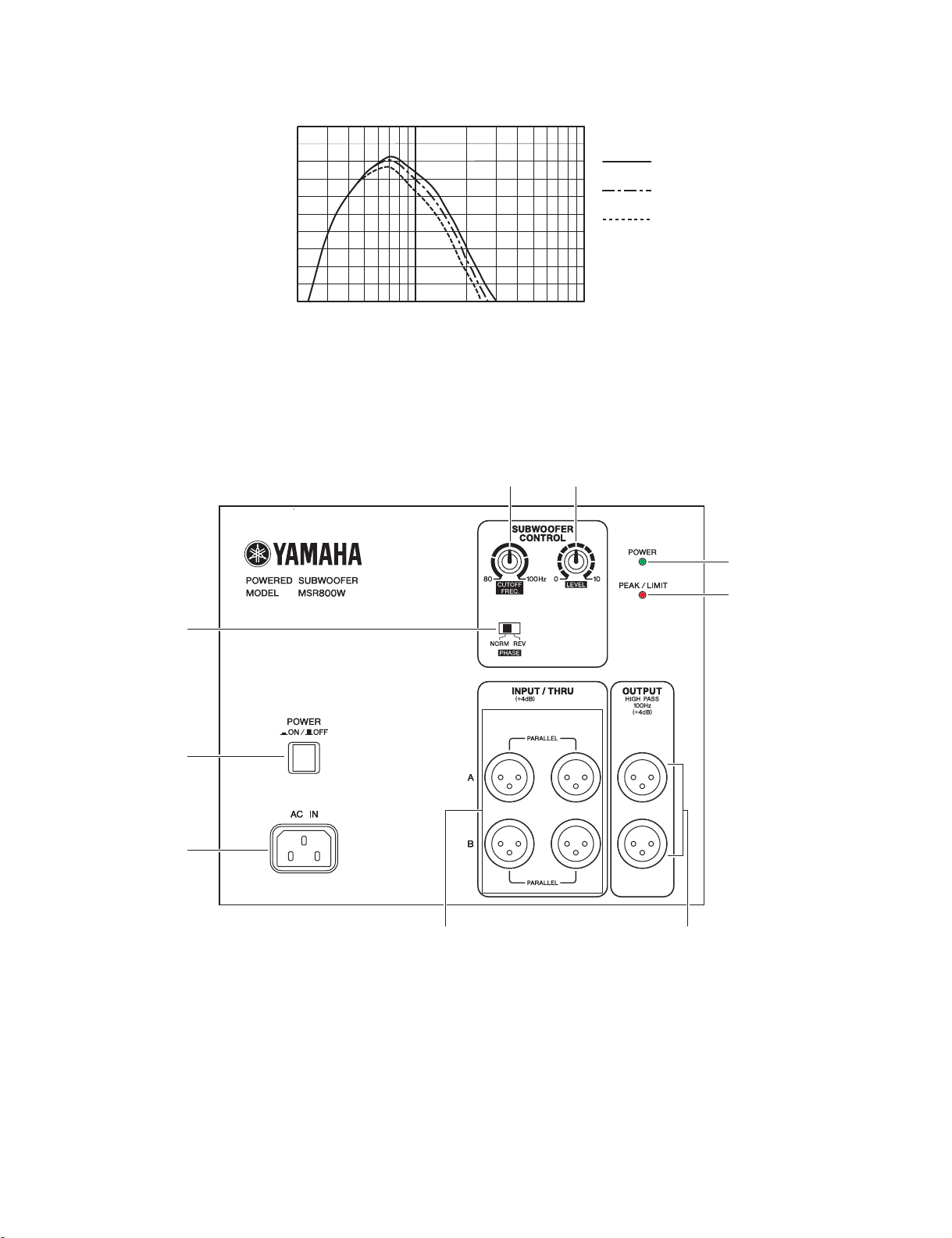
■ PERFORMANCE GRAPH(特性図)
+10
0
–10
–20
RESPONSE (dB)
–30
–40
20
FREQUENCY (Hz)
■ PANEL LAYOUT(パネルレイアウト)
• Rear Panel(リアパネル)
Cutoff Frequency
100Hz
90Hz
80Hz
<SPL>
1k100
98
7
1
2
3
1 PHASE switch
2 POWER switch
3 AC IN connector
4 INPUT/THRU A/B connectors
5 OUTPUT HIGH PASS A/B connectors
6 PEAK/LIMIT indicator
7 POWER indicator
8 LEVEL control
9 CUTOFF FREQ. control
6
54
1 PHASE スイッチ
2 POWER スイッチ
3 AC IN 端子
4 INPUT/THRU A/B 端子
5 OUTPUT HIGH PASS A/B 端子
6 PEAK/LIMIT インジケーター
7 POWER インジケーター
8 LEVEL コントロール
9 CUTOFF FREQ. コントロール
4
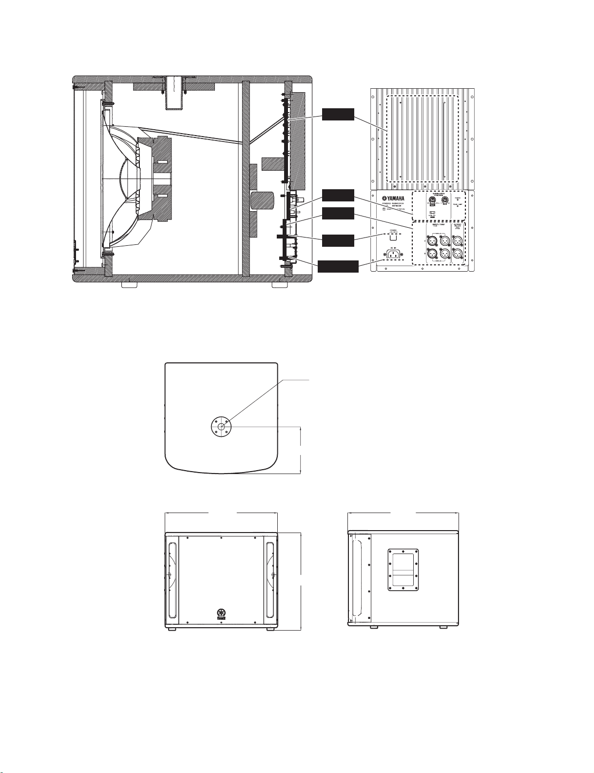
■ CIRCUIT BOARD LAYOUT(ユニットレイアウト)
AMP
MIX
INPUT
SW
AC INLET
MSR800W
■ DIMENSIONS(寸法図)
600.0
φ35.0
250.0
590.0
521.0
Unit: mm
(単位)
5
MSR800W
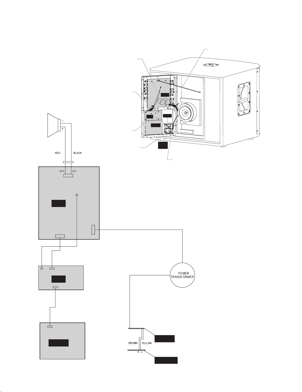
■ WIRING DIAGRAM(結線図)
• VERSION: U, H, B, A, O
Connector Assembly
Connector Assembly
WOOFER
Connector 4P (2P)
Connector Assembly
Connector Assembly
2P L=250
(束線)
6P L=80
(束線)
4P L=100
(束線)
1P GND
(束線)
CN106
MIX
CN201
CN105
INPUT
CN203
CN204
AMP
CN102
AC
INLET
CN202
SW
CN101
L
N
Connector Assembly 6P L=100
(束線)
Connector Assembly 4P L=800
(束線)
BB
CN106-2P
4321
CN203-4P
CN204-2P
AMP
CN202-6P
CN201-6P
CN105-6P
MIX
CN104-4P
B
CN103-4P
CN102-3P (2P)
CN101-3P (2P)
SW
INPUT
B
AC INLET
6
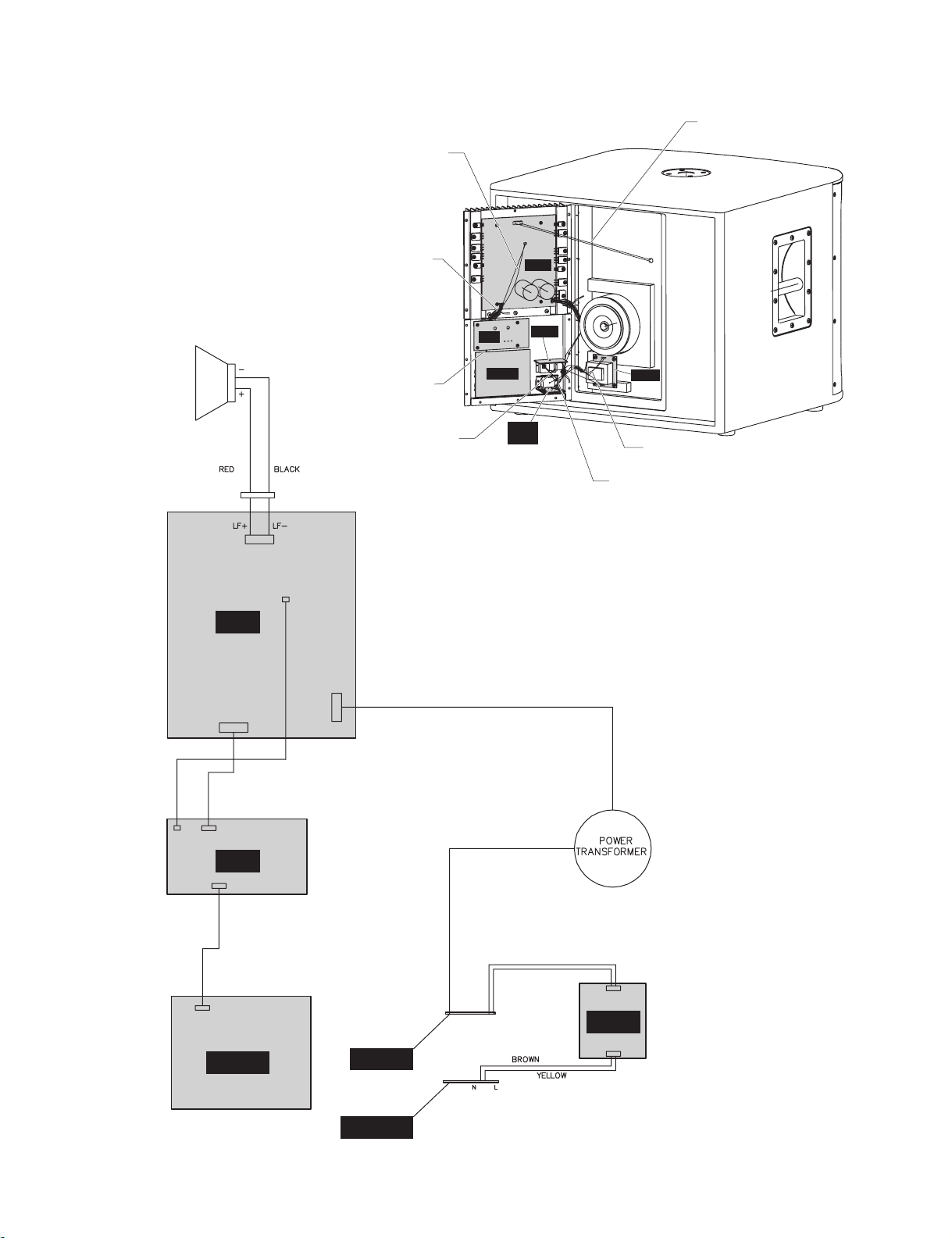
• VERSION: J
WOOFER
Connector Assembly
Connector Assembly
Connector Assembly
Connector Assembly
Connector 4P (2P)
2P L=250
(束線)
6P L=80
(束線)
4P L=100
(束線)
1P GND
(束線)
CN106
CN201
MIX
INPUT
CN105
CN203
INLET
AC
CN204
AMP
CN102
CN202
SW
CN101
N
MSR800W
Connector Assembly 4P L=800
(束線)
CN302
HARM
CN301
L
Connector Assembly 3P L=150
(束線)
Connector Assembly 3P L=180
(束線)
BB
CN106-2P
B
CN103-4P
CN203-4P
AMP
CN201-6P
CN105-6P
MIX
CN104-4P
INPUT
4321
CN204-2P
CN202-6P
CN102-3P (2P)
SW
CN101-3P (2P)
B
CN302-3P (2P)
HARM
CN301-3P (2P)
AC INLET
7
MSR800W
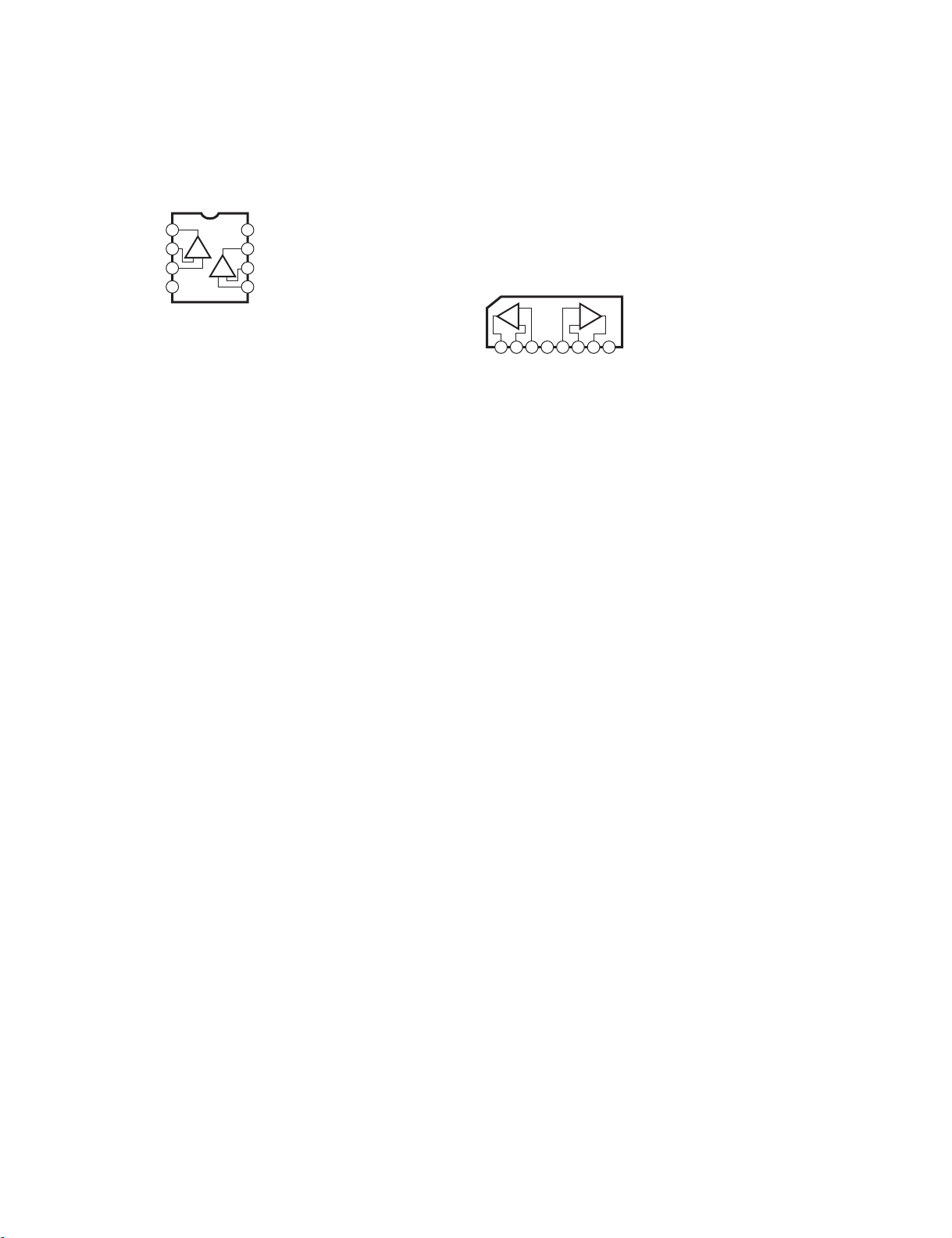
■ IC BLOCK DIAGRAM(IC ブロック図)
• TL072CP (AAX67450)
INPUT: IC103
Dual Operational Amplifier
+DC Voltage
Output A
Inverting
Input A
Non-Inverting
Input A
-DC Voltage Supply
1
2
3
4–V
8
+V
Supply
7
+–
Output B
Inverting
6
Input B
Non-Inverting
5
Input B
+ –
• NJM2068L-D (AAX64880)
MIX: IC106, IC107, IC108, IC109
INPUT: IC102, IC104
• NJM4580L (AAX67460)
INPUT: IC101, IC105
Dual Operational Amplifier
+
-
1A2 3 4 5 6 7 8
OUTA-INA+INA+INB-INBOUT
+
B
-
-V +V
B
8
MSR800W
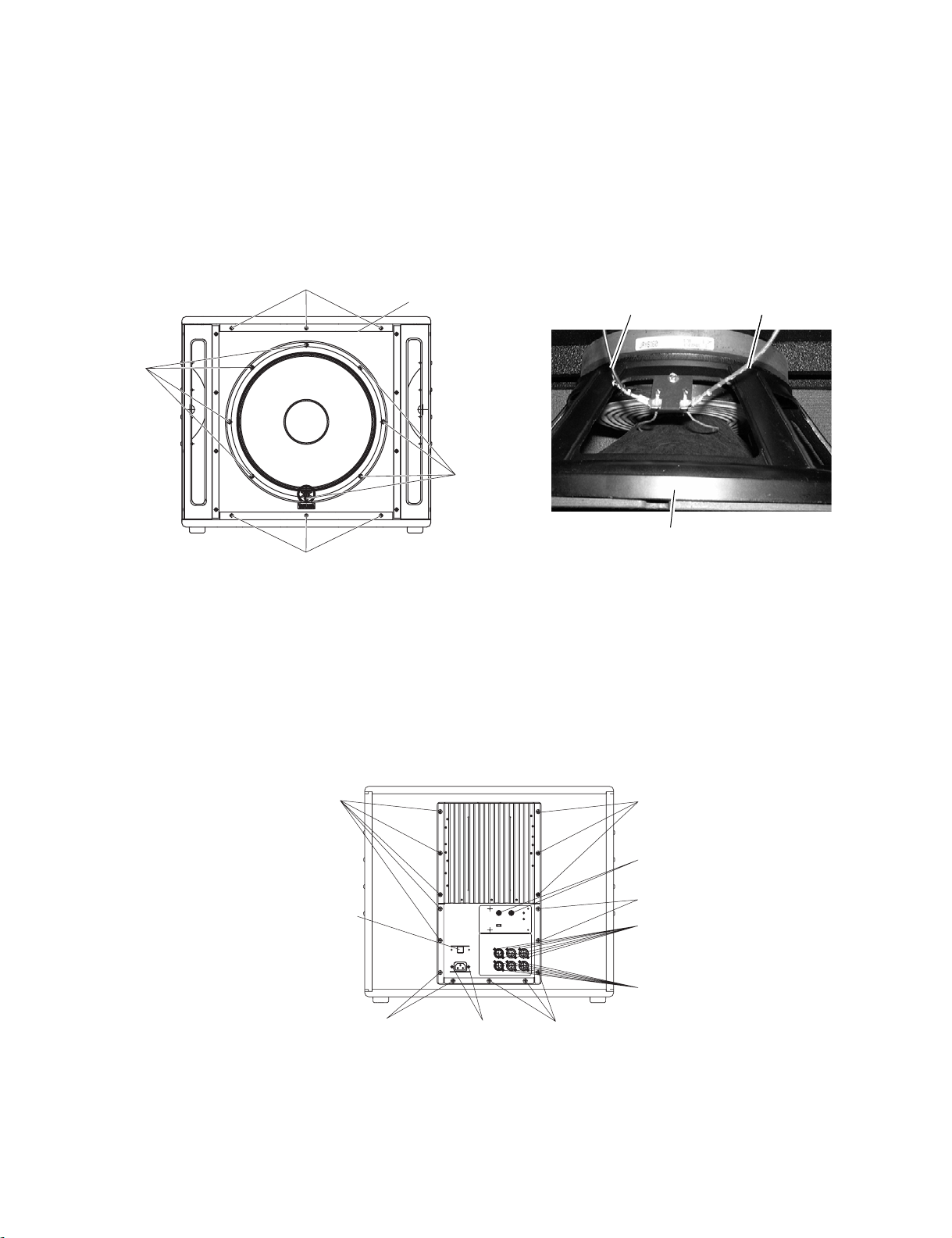
■ DISASSEMBLY PROCEDURES
1. Woofer (Time required: about 10 minutes)
1-1. Remove the six (6) screws marked [1]. The speaker grille
■ 分解手順
1. ウーファー(所要時間:10 分)
1-1. [1] のネジ 6 本を外し、 ス ピーカーグリルを外します。
can be removed. (Fig.1)
1-2. Remove the eight (8) screws marked [3]. The woofer can
then be removed. (Fig.1)
1-2. [3] のネジ 8 本を外 し 、 ウーフ ァ ー を 外 し ま す。 (図 1)
1-3. SP 束線 (黒 /赤) を ウーフ ァ ーか ら取 り 外 し ます。 (写
1-3. Remove the SP connector assembly (red/black) installed to
the woofer. (Photo.1)
[1] Speaker grille
[3]
[1]
[1]: Bind Head Wood Screw 4x14 MFZN2BL (AAX67400) +バインド木ネジ
[3]: Bind Head Screw 5x25 MFZN2BL (AAX67390) +バインド小ネジ
(スピーカーグリル)
[3]
(図 1)
真 1)
SP Connector
Assembly (Black)
(SP 束線黒)
Woofer
(ウーファー)
Photo.1 (写真 1)
SP Connector
SP Connector
Assembly (Red)
Assembly (Red)
(SP 束線赤)
(SP 束線赤)
Fig.1 (図 1)
2. Amplifier Assembly
(Time reguired: about 5 minutes)
2-1. Remove the fifteen (15) screws marked [3].
The amplifier assembly can be removed. (Fig.2)
[3]
Power switch knob
(パワースイッチノブ)
[3]
[3]: Bind Head Screw 5x25 MFZN2BL (AAX67390) +バインド小ネジ
[A4]: Bind Head Screw 3x10 MFZN2BL (AAX64750) +バインド小ネジ
[A6]: Bonding Tapping Screw-B 3x8 MFZN2BL (AAX64840) ボンディングB タイト
2. アンプ Ass’y (所要時間:5 分)
2-1. [3] のネジ 15 本を外し、アンプAss’y を外し ます。(図 2)
[3]
Rotation knob
(ローテーションノブ)
[3]
[A6]
[A6]
[3][A4]
Fig.2 (図 2)
9
MSR800W
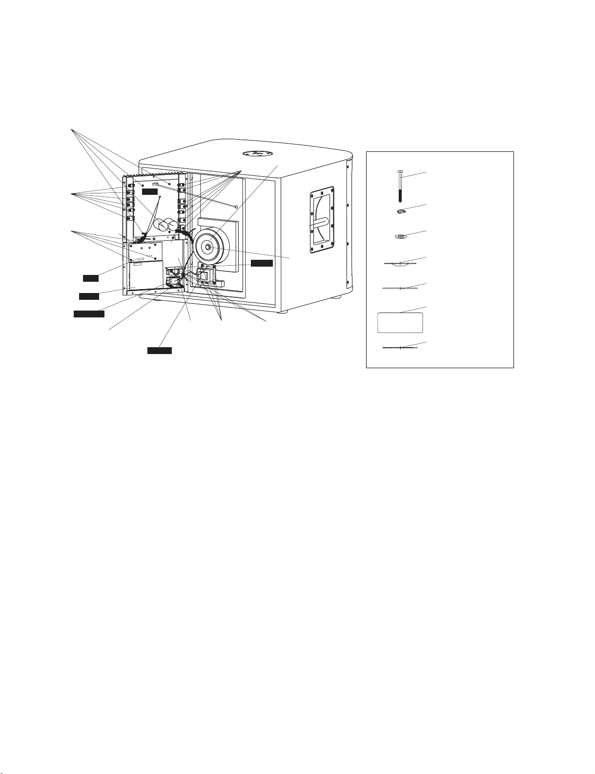
3. Power Transformer
(Time required: about 10 minutes)
3-1. Remove the amplifier assembly. (See procedure 2.)
3-2. Remove the hexagonal bolt of the power transformer. The
power transformer can then be removed. (Fig.3 & Fig.4)
[A1]
[A5]
CN203
CN105
CN104
CN103
AMP
CN201
HARM
CN204
CN202
CN102
CN101
(J model)
CN302
[A3]
CN301
[1]
L
N
SW
[A1]
[A5]
[A1]
INPUT
AC INLET
CN106
MIX
Bracket AC jack support
(ブラケット/ACジャック)
3. 電源トランス (所要時間:10 分)
3-1. アンプAss’y を外し ま す。 (2 項参照)
3-2. 電源 ト ラ ン ス の六角ボル ト を 外 し、 電源 ト ラ ン ス を外
し ます。 (図 3、図4)
• Power Transformer Installation
(電源トランスの取り付け詳細)
Power transformer
(電源トランス)
Hexagonal bolt
(六角ボルト)
Hexagonal bolt
(六角ボルト)
Spring washer
(バネ座金)
Flat washer
(平座金)
Transformer holder
(トランスホルダー)
Rubber pad
(ゴムパッド)
Power transformer
(電源トランス)
Rubber pad
(ゴムパッド)
[1]: Bind Head Wood Screw 4x14 MFZN2BL (AAX67400) +バインド木ネジ
[A1]: Bind Head Screw 3x6 MFZN2BL (AAX64740) +バインド小ネジ
[A3]: Bind Head Tapping Screw-B 4x8 MFZN2BL (AAX64730) +バインドB タイト
[A5]: Bind Head Sems Screw 3x12 MFZN2BL (AAX64760) +バインドセムス小ネジ
Fig.3 (図 3)
4. AMP Circuit Board
(Time required: about 15 minutes)
4-1. Remove the amplifier assembly. (See procedure 2.)
4-2. Disconnect the connectors (CN201, CN202, CN203,
CN204). (Fig.3)
4-3. Remove the thirteen (13) screws marked [A5]. (Fig.3)
4-4. Remove the four (4) screws marked [A1] on the AMP
4. AMP シート (所要時間:15 分)
4-1. アンプAss’y を外し ま す。 (2 項参照)
4-2. コネク ター (CN201、 CN202、 CN203、 CN204)の接
続を外し ます。 (図3)
4-3. [A5] のネジ 13 本を外します。 (図3)
4-4. [A1] のネジ 4 本を外し、AMP シー ト を外し ます。(図3)
circuit board. The AMP circuit board can then be removed.
(Fig.3)
5. INPUT Circuit Board
(Time required: about 10 minutes)
5-1. Remove the amplifier assembly. (See procedure 2.)
5-2. Remove the twelve (12) screws marked [A6]. The INPUT
circuit board can then be removed. (Fig.2)
5-3. Disconnect the connectors (CN103). (Fig.3)
5. INPUT シート
(所要時間:10 分)
5-1. アンプAss’y を外し ま す。 (2 項参照)
5-2. [A6] のネジ 12 本を外し、 INPUT シー ト を外 し ます。
(図 2)
5-3. コネクター (CN103) の接続を外 し ま す。 (図 3)
Fig.4
(図 4)
10
MSR800W
6. MIX Circuit Board
(Time required: about 10 minutes)
6-1. Remove the two (2) rotation knobs from the rear panel
side. (Fig.2)
6-2. Remove the amplifier assembly. (See produre 2.)
6-3. Remove the four (4) screws marked [A1] on the MIX
circuit board. The MIX circuit board can then be removed.
(Fig.3)
6-4. Disconnect the connectors (CN105, CN106). (Fig.3)
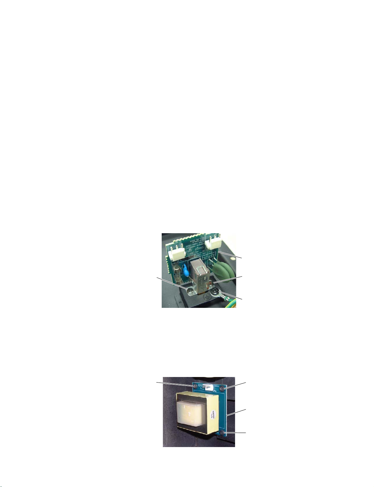
7. SW Circuit Board
(Time required: about 10 minutes)
7-1. Remove the power switch knob. (Fig.2)
7-2. Remove the amplifier assembly. (See procedure 2.)
7-3. Disconnect the connectors (CN101, CN102). (Fig.3)
7-4. Remove the two (2) screws marked [A1] on the SW circuit
board. The SW circuit board can then be removed. (Fig.3
& Photo.2)
8. AC INLET Circuit Board
(Time required: about 10 minutes)
8-1. Remove the amplifier assembly. (See procedure 2.)
8-2. Disconnect the connectors(CN102). (Fig.3)
8-3.
Remove two (2) screws marked [A4] and the screw marked
[A3]. The AC INLET circuit board and the Bracket AC
Jack Support can then be removed. (Fig.2, Fig.3 & Photo.2)
6. MIX シート (所要時間:10 分)
6-1. ローテーシ ョ ン ノブ2 個を外します。 (図2)
6-2. アンプAss’y を外 し ます。 (2 項参照)
6-3. [A1] のネジ 4 本を外し、MIX シー ト を外 し ます。(図 3)
6-4. コネクター(CN105、CN106) の接続を外 し ます。(図 3)
7. SW シート (所要時間:10 分)
7-1. パワース イ ッチノ ブを外します。 (図2)
7-2. アンプAss’y を外 し ます。 (2 項参照)
7-3. コネクター(CN101、CN102) の接続を外 し ます。(図 3)
7-4. [A1] のネジ 2 本を外し、 SW シー ト を外し ます。(図3、
写真 2)
8. AC INLET シート (所要時間:10 分)
8-1. アンプAss’y を外 し ます。 (2 項参照)
8-2. コネクター (CN102) の接続を 外 し ます。 (図 3)
8-3. [A4] のネジ 2 本と[A3] のネジ1 本を外し、 AC INLET
シー ト と ブラ ケ ッ ト /AC ジ ャ ッ ク を外 し ま す。 (図 2、
図 3、写真2)
Photo.2 (写真 2)
9. HARM Circuit Board
(Time required: about 10 minutes) (J model only)
9-1. Remove the amplifier assembly. (See procedure 2.)
9-2. Disconnect the connectors (CN301, CN302). (Fig.3)
9-3. Remove the four (4) screws marked [1]. The HARM circuit
board can then be removed. (Fig.3 & Photo.3)
[1]
SW Circuit Board
(SW シート)
[A1][A1]
[A3]
9. HARM シート (所要時間:10 分)(J 仕向のみ)
9-1. アンプAss’y を外 し ます。 (2 項参照)
9-2. コネクター(CN301、CN302) の接続を外 し ます。(図 3)
9-3. [1] のネジ 4 本を外し、 HARM シー ト を外し ます。
(図 3、写真3)
[1]
HARM Circuit Board
(HARM シート )
[1]
Photo.3 (写真 3)
11
 Loading...