

YAMAHA MK175K2U PARTS CATALOGUE
YAMAHA MULTI−PURPOSE ENGINE
MK175K2U
(7WC3) KOHLER
1A7WC−110E1

MK175K2U
PARTS CATALOGUE
E2002 by Yamaha Motor Co., Ltd.
1st Edition, Aug. 2002
All rights reserved.
Any reprinting or unauthorized use
without the written permission of
Yamaha Motor Co., Ltd.
is expressly prohibited.
Printed in Japan
FOREWORD
This Parts Catalogue is related to the parts for the model(s) in the below frame. When you are
ordering replacement parts, please refer to this Parts Catalogue and quote both part numbers
and part names correctly.
1. Modifications or additions which have been made after issue of the Parts Catalogue
will be announced in the Yamaha Parts News.
It is advisable that you make necessary corrections to the Parts Catalogue according
to the Yamaha Parts News.
2. Abbreviations
The following abbreviations are used in this Parts Catalogue.
“UR” Use specified parts number.
“UN” Use as many as needed.
“AP” Alternate Parts
“LM” Local Made (Parts need to be ordered locally)
“F#” Frame No. (Applicable machine No.)
3. Parts, which are to be supplied in an assembly, are listed with a dot(.) in front of the
part name as shown below.
EXAMPLE
CARBURETOR ASSY
.JET, PILOT
.NOZZLE, MAIN
5. Applicable colors of graphics are represented in the REMARKS as shown below.
PART NO. DESCRIPTION Q’TY REMARKS
7UF−24110−00−98 FUEL TANK COMP. 1 LGB
7UF−24610−00 CAP ASSY 1
6. Applicable Serial No. and Color Code
See the Serial No list on next page.
Serial No.
Color
Code
0098 LOW GLOSS BLACK LGB
7. Note that the illustraitions for reference in finding parts numbers, not be used for assembling. When assembling, please use the applicable service manual.
Color Name
Abbrevi-
ation
4. Number of component for assembly
The numeral appearing to the right of each component part indicates the quantity of
parts for each assembly unit.
EXAMPLE
PART NO. DESCRIPTION Q’TY REMARKS
2F5−83310−60 FRONT FLASHER LIGHT ASSY 2
115−83311−60 .BULB (6V−18W) 1
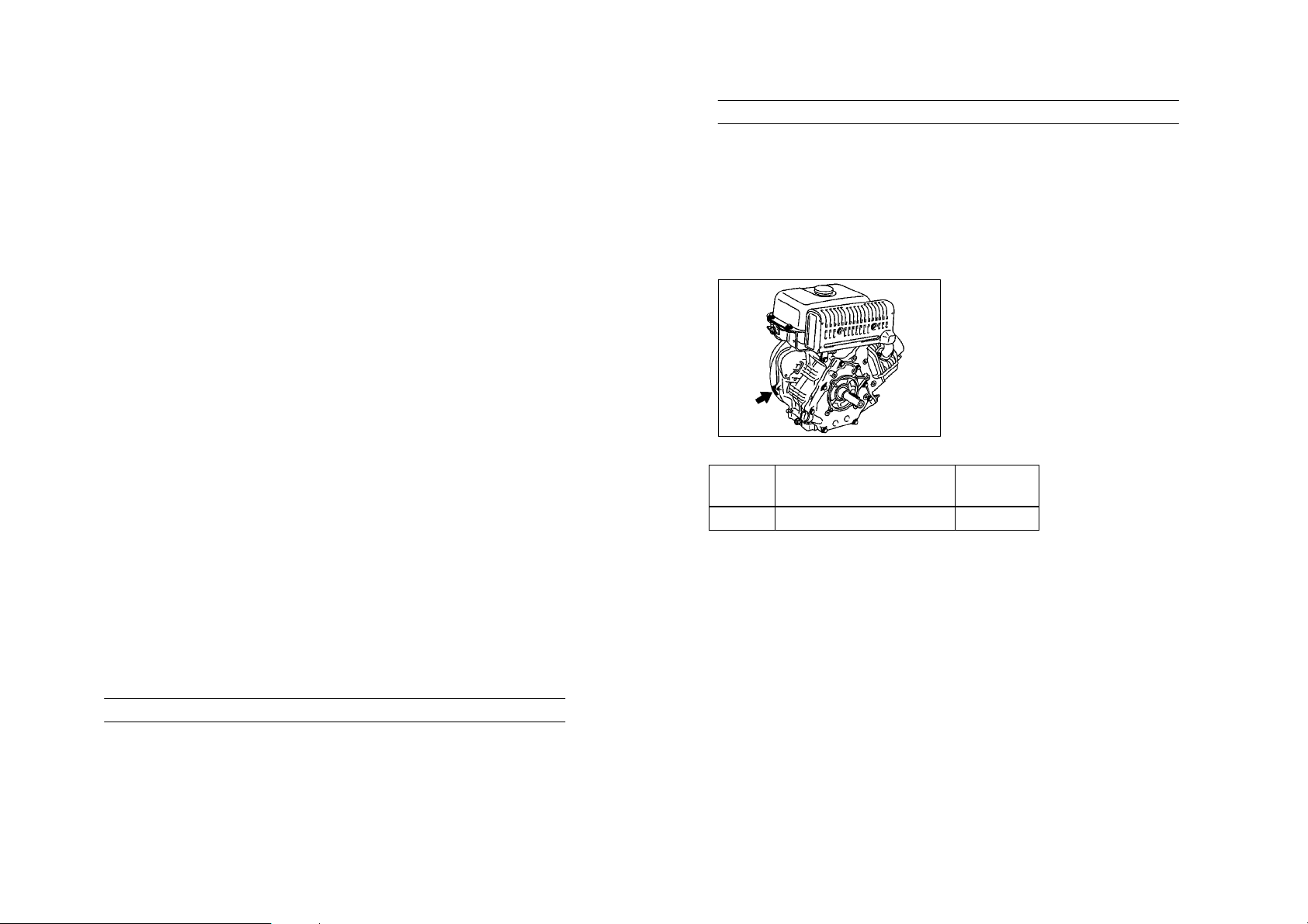
Engine Serial No.
This parts catalogue is r el ated to the par ts for the models in the list below.
MODEL CODE MODEL NAME SPECIFICATION (OUT LINE) ENGINE SERIAL NO KOHLER SPEC NO
7WC3 MK175K2U F/T LESS, A/C MZ TYPE 7WC−0360101 911517

CYLINDER 1.........................................
CRANKSHAFT 2......................................
CRANKSHAFT. PISTON 3..............................
GOVERNOR 1 4......................................
CAMSHAFT. VALVE 5.................................
AIR SHROUD. STARTER 6.............................
INTAKE 1 7...........................................
CARBURETOR 8.....................................
CRANKCASE 9.......................................
MAGNETO 10.........................................
EMBLEM. LABEL 11....................................
BODY FITTING 12.....................................
INDEX
NUMERICAL INDEX 13.................................
CONTENTS
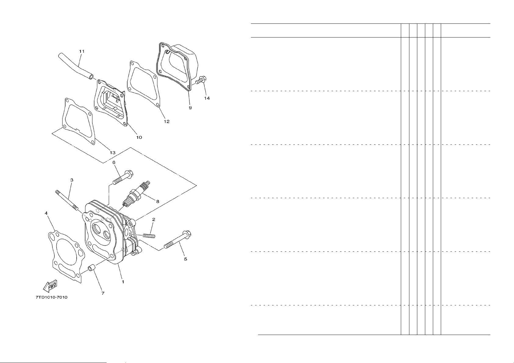
FIG. 1 CYLINDER
REF.
NO.
10 7NJ−11160−00 BREATHER ASSY 1
11 90445−131J5 HOSE (L106) 1
12 7NJ−11169−00 GASKET, BREATHER COVER 1
13 7NJ−11193−00 GASKET, HEAD COVER 1 1
14 95827−06012 BOLT, FLANGE 4
PART NO. DESCRIPTION REMARKS
1 7WC−11111−00 HEAD, CYLINDER 1 1
2 95607−06615 NUT, FLANGE 2
3 90116−06493 BOLT, STUD 2
4 7WC−11181−00 GASKET, CYLINDER HEAD 1 1
5 95827−08065 BOLT, FLANGE 2
6 95827−08045 BOLT, FLANGE 2
7 99530−10114 PIN, DOWEL 2
8 94702−00331 PLUG, SPARK (BPR4ES) 1
9 7NJ−11191−00 COVER, CYLINDER HEAD 1 1
7WC3
1
 Loading...