

Yamaha M7CL Service Manual
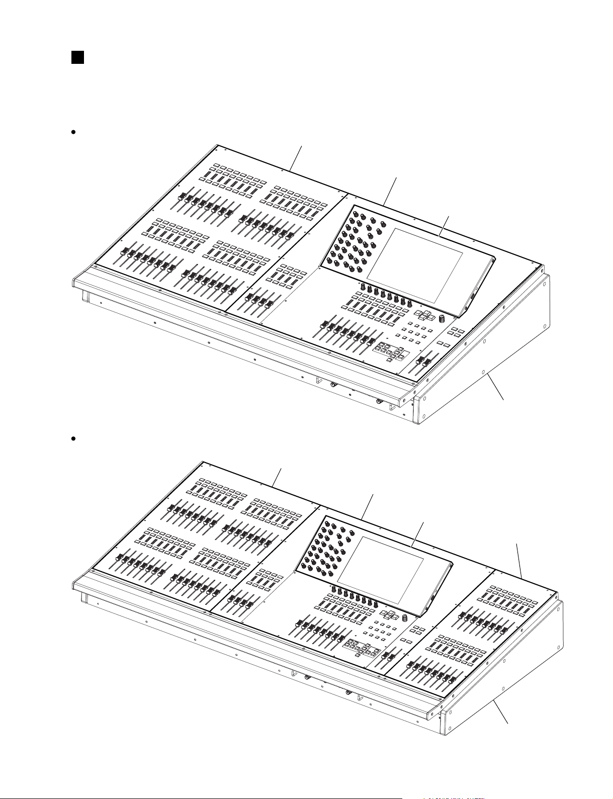
•M7CL-32
•M7CL-48
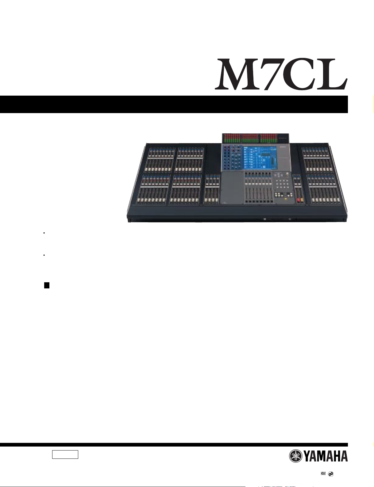
M7CL-32/M7CL-48
DIGITAL MIXING CONSOLE
SERVICE MANUAL
OPTION
METER BRIDGE
(オプション)
MBM7CL
POWER SUPPLY LINK CABLE
PSL360
CONTENTS
SPECIFICATIONS ................................... 5
CONNECTOR PIN ASSIGNMENTS
(コネクターピンアサイン表)
PANEL LAYOUT ................... 11
DIMENSIONS ......................................... 17
CIRCUIT BOARD LAYOUT
(ユニットレイアウト)
DISASSEMBLY PROCEDURE ............ 24
LSI PIN DESCRIPTION .............. 52
IC BLOCK DIAGRAM ................... 62
CIRCUIT BOARDS ........................ 67
INSPECTIONS .................................. 118/122
SERVICE CHECK PROGRAM
(サービス検査プログラム)
PROCEDURE TO CAPTURE SCREEN
(スクリーンショットの手順)
INSTALLING an OPTION CARD
(オプションカードの取り付け)
USER SETTINGS (SECURITY)
(ユーザー設定(セキュリティ))
(目次)
(
総合仕様
(パネルレイアウト)
(寸法図)
(ICブロック図)
(シート基板図)
(検査)
)
................................ 10
........................................... 19
(分解手順)
(LSI端子機能表)
......................... 126/140
............................. 154
.................. 155/156
............... 157/173
M7CL-48/MBM7CL
INITIALIZING THE M7CL’s INTERNAL MEMORY
(M7CLの内蔵メモリーを初期化する)
CALIBRATION FUNCTION
(キャリブレーション機能)
WARNING/ERROR MESSAGES
(ワ−ニング/エラーメッセージ)
MIDI IMPLEMENTATION CHART .......................201
MIDI DATA FORMAT .......................................... 202
PARTS LIST
BLOCK DIAGRAM
OVERALL CONNECTOR CIRCUIT DIAGRAM
(総コネクタ接続回路図)
CIRCUIT DIAGRAM
MBM7CL PARTS LIST
MBM7CL BLOCK DIAGRAM
MBM7CL CIRCUIT DIAGRAM
PSL360 PARTS LIST
(ブロックダイアグラム)
(回路図)
......................... 191/194
(ブロックダイアグラム)
(回路図)
........ 189/190
............... 197/199
011804
PA
M7CL-32: 20051101-2250000
M7CL-48: 20051101-2750000
MBM7CL: 20051101-130000
PSL360: 20051101-オープンプライス
HAMAMATSU, JAPAN
Copyright (c) Yamaha Corporation. All rights reserved. PDF ’05.11
1
M7CL-32/M7CL-48
IMPORTANT NOTICE
This manual has been provided for the use of authorized Yamaha Retailers and their service personnel. It has been assumed that basic
service procedures inherent to the industry, and more specifically Yamaha Products, are already known and understood by the users,
and have therefore not been restated.
WARNING : Failure to follow appropriate service and safety procedures when servicing this product may result in personal injury,
IMPORTANT : This presentation or sale of this manual to any individual or firm does not constitute authorization certification,
The data provided is belived to be accurate and applicable to the unit(s) indicated on the cover. The research engineering, and service
departments of Yamaha are continually striving to improve Yamaha products. Modifications are, therefore, inevitable and changes in
specification are subject to change without notice or obligation to retrofit. Should any discrepancy appear to exist, please contact the
distributor’s Service Division.
WARNING : Static discharges can destroy expensive components. Discharge any static electricity your body may have accumulated
destruction of expensive components and failure of the product to perform as specified. For these reasons, we advise
all Yamaha product owners that all service required should be performed by an authorized Yamaha Retailer or the
appointed service representative.
recognition of any applicable technical capabilities, or establish a principal-agent relationship of any form.
by grounding yourself to the ground bus in the unit (heavy gauge black wires connect to this bus.)
IMPORTANT : Turn the unit OFF during disassembly and parts replacement. Recheck all work before you apply power to the unit.
WARNING: CHEMICAL CONTENT NOTICE!
The solder used in the production of this product contains LEAD. In addition, other electrical/electronic and/or plastic (Where applicable)
components may also contain traces of chemicals found by the California Health and Welfare Agency (and possibly other entities) to cause
cancer and/or birth defects or other reproductive harm.
DO NOT PLACE SOLDER, ELECTRICAL/ELECTRONIC OR PLASTIC COMPONENTS IN YOUR MOUTH FOR ANY REASON WHAT SO EVER!
Avoid prolonged, unprotected contact between solder and your skin! When soldering, do not inhale solder fumes or expose eyes to solder/
flux vapor!
If you come in contact with solder or components located inside the enclosure of this product, wash your hands before handling food.
LITHIUM BATTERY HANDLING
This product uses a lithium battery for memory back-up.
WARNING : Lithium batteries are dangerous because they can be exploded by improper handling. Observe the following precautions
Leave lithium battery replacement to qualified service personnel.
Always replace with batteries of the same type.
When installing on the PC board by soldering, solder using the connection terminals provided on the battery cells.
Never solder directly to the cells. Perform the soldering as quickly as possible.
Never reverse the battery polarities when installing.
Do not short the batteries.
Do not attempt to recharge these batteries.
Do not disasemble the batteries.
Never heat batteries or throw them into fire.
ADVARSEL!
Lithiumbatteri-Eksplosionsfare ved fejlagtig håndtering. Udskiftning må kun ske med batteri af samme fabrikat og type. levér det brugte batteri tilbage
til leverandren.
VARNING
Explosionsfara vid felaktigt batteribyte.
Använd samma batterityp eller en ekvivalent typ som rekommenderas av apparattillverkaren.
Kassera använt batteri enligt fabrikantens instruktion.
VAROITUS
Paristo voi räjähtää, jos se on virheellisesti asennettu.
Vaihda paristo ainoastaan laitevalmistajan suosittelemaan tyyppiiin.
Hävitä käytetty paristo valmistajan ohjeiden mukaisesti.
The following information complies with Dutch official Gazette 1995. 45; ESSENTIALS OF ORDER ON THE COLLECTION OF BATTERIES.
• Please refer to the diassembly procedure for the removal of Back-up Battery.
• Leest u voor het verwijderen van de backup batterij deze beschrijving.
when handling or replacing lithium batteries.
リチウム電池の取り扱い
<注意>
リチウム電池を誤って交換すると爆発する危険があります。交換する場合は、サービスマニュアルで指定された部品を使用して
ください。
WARNING
Components having special characteristics are marked and must be replaced with parts having specification equal to those
originally installed.
印の商品は、安全を維持するために重要な部品です。交換する場合は、安全のために必ず指定の部品をご使用ください。
2
IMPORTANT NOTICE FOR THE UNITED KINGDOM
p
Connecting the Plug and Cord
WARNING: THIS APPARATUS MUST BE EARTHED
IMPORTANT. The wires in this mains lead are coloured in accordance
with the following code:
GREEN-AND-YELLOW : EARTH
BLUE : NEUTRAL
BROWN : LIVE
As the colours of the wires in the mains lead of this apparatus may not
correspond with the coloured markings identifying the terminals in your
plug proceed as follows:
The wire which is coloured GREEN-and-YELLOW must be connected to
the terminal in the plug which is marked by the letter E or by the safety
earth symbol or colored GREEN or GREEN-and-YELLOW.
The wire which is coloured BLUE must be connected to the terminal
which is marked with the letter N or coloured BLACK.
The wire which is coloured BROWN must be connected to the terminal
which is marked with the letter L or coloured RED.
M7CL-32/M7CL-48
Take care not to trap your fingers.
(作業中は指を挟まない様に注意してください。)
BACKUP BATTERY
This device has a built-in backup battery. When you unplug the power cord from the AC outlet, the current scene data and
library data is retained. Howe v er, if the backup battery fully discharges, this data will be lost. When the backup battery is running
low, the LCD display indicates “Low Battery!” when you start up the system. (The Battery field indicates “LOW” or “NO” in the
Be sure to
erform it
SET UP screen.) In this case, immediately save the data to a USB storage device.
この機器はバックアップバッテリーが内蔵されていますので、電源プラグがコンセントから外されても、電源を切ったとき
のカレントシーンデータやライブラリーデータは保持されます。ただし、バックアップバッテリーが消耗すると、カレント
シーンデータやライブラリーデータは消えてしまいます。バックアップバッテリーが消耗してくると、起動時にLo w
Battery!と表示されます(SETUP画面の Battery欄でもバッテリーが消耗してくると LOWまたは NOと表示されます)。
その場合は、すぐにデータを USB記憶装置に保存してください。
USER LEVEL SETTINGS
User Level settings allow you to restrict the parameters that can be operated by each user, or to change the settings of user-defined keys and
preference settings for each user. Settings for each user can be stored as a “user authentication k ey” on a USB storage device, allowing users
to be switched easily, simply by connecting this storage device to a USB connector. This is convenient in the following situations.
• Unintended or mistaken operation can be prevented.
• The range of functionality operable by an outside engineer (guest engineer) can be limited.
• In situations in which multiple operators alternate with each other , output settings etc. can be locked to prevent unintended operations.
• Preferences of each operator can easily be switched.
(バックアップバッテリー)
(ユーザーレベル設定)
User settings may be stored by users. To service the device, get the USB storage device storing the "user authentic key" from the user.
ユーザーレベルを設定することにより、操作できるパラメーターをユーザーごとに制限したり、ユーザー定義キーやプリファレンス設定を
ユーザーごとに切り替えたりすることができます。ユーザーごとの設定は「ユーザー認証キー」としてUSB記憶装置にまとめて記憶してお
いて、これを USB端子に挿入することで簡単にユーザーを切り替えることができます。たとえば、以下のような場合に便利です。
・ 不用意な誤操作を防止できます。
・ 外部のエンジニア(ゲストエンジニア)が操作できる範囲を制限できます。
・ 複数のオペレーターが交代で操作する場合などに、出力設定をロックするなどして、誤操作を防止できます。
・ オペレーターごとに好みの設定に簡単に切り替えられます。
ユーザーがユーザーレベルを設定している場合がありますので、サービス実施時には、ユーザーから「ユーザー認証キー」を記憶してある
USB 記憶装置を借りてください。
3
M7CL-32/M7CL-48
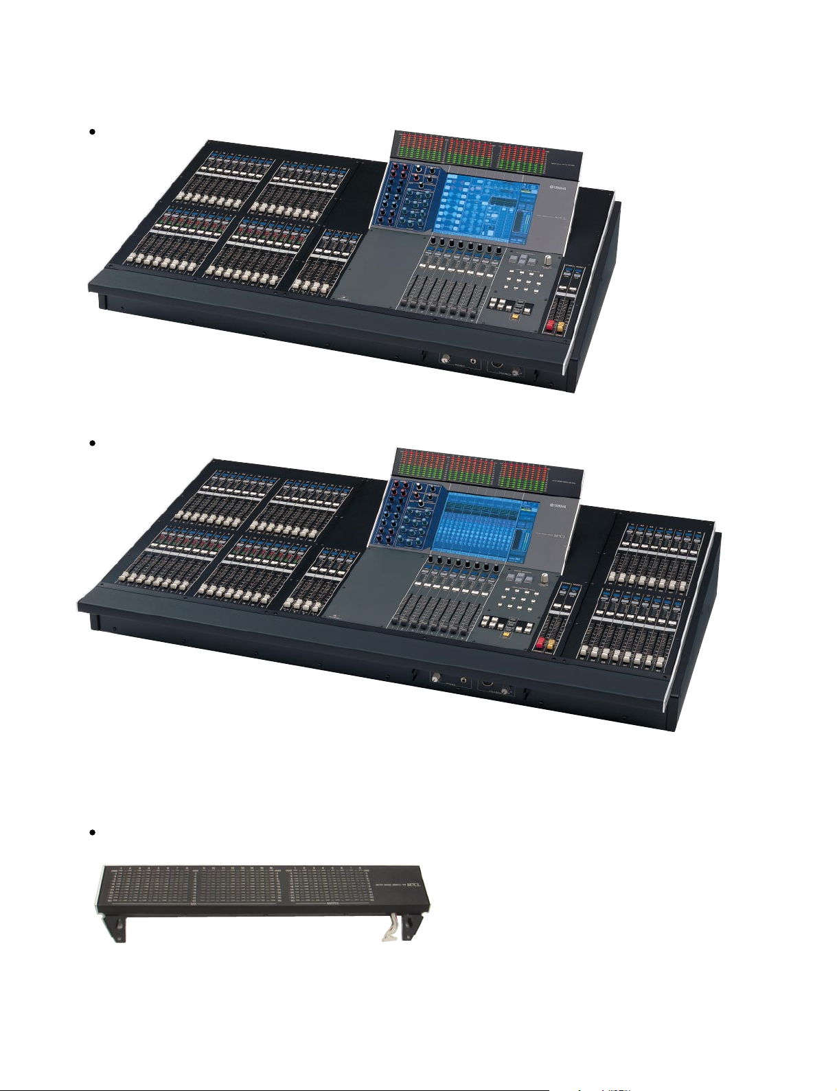
M7CL-32
M7CL-48
MBM7CL (Option)
4
M7CL-32/M7CL-48
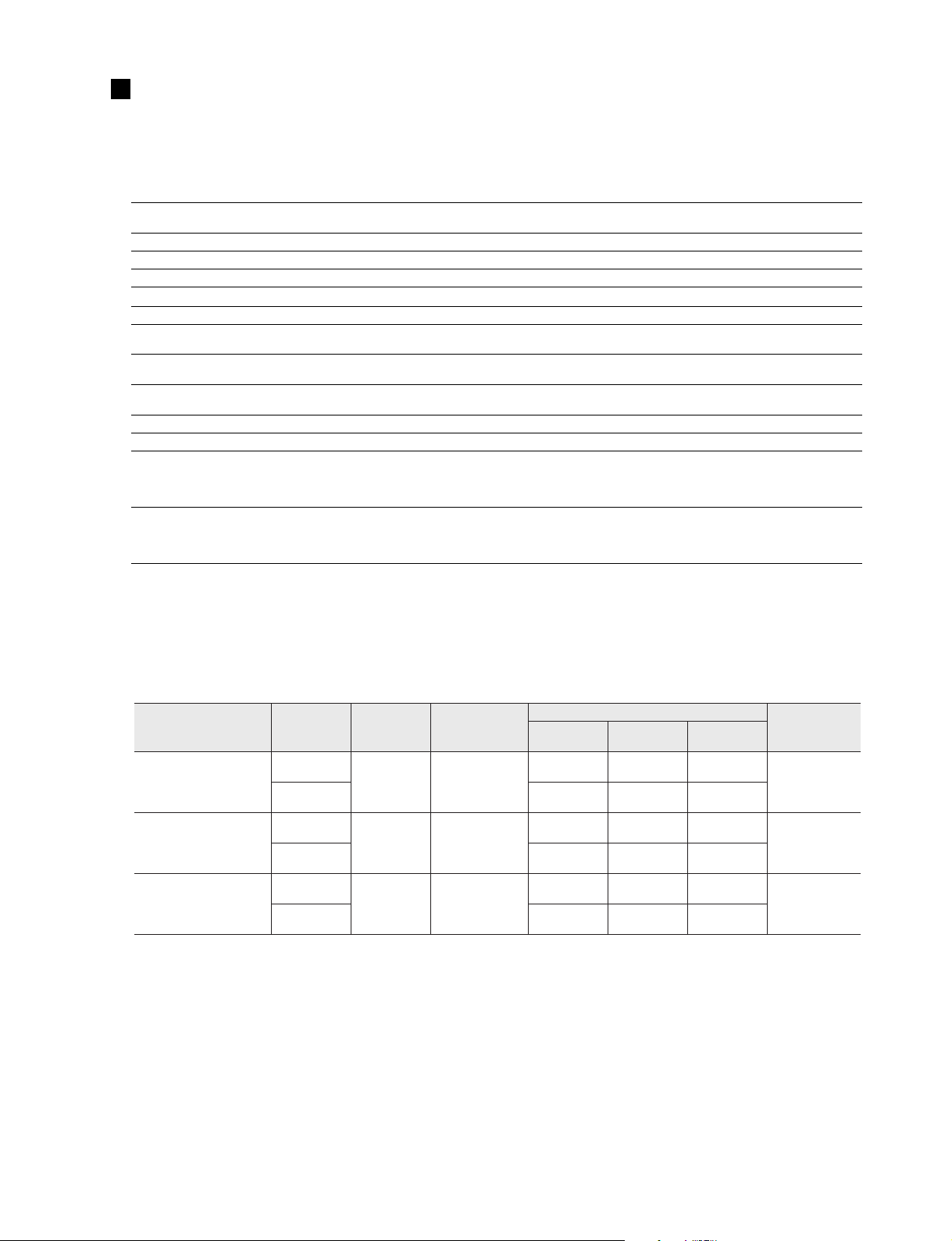
SPECIFICATIONS
(総合仕様)
• M7CL-32/M7CL-48
1. General Specifications
Sampling Frequency
Signal Delay
Fader 100mm motorized x62 (46)
Fader Resolution +10 to
Maximum Voltage Gain
Crosstalk (@1kHz)
Dimensions
Net Weight
Power Requirements
Operation free-air Temperature Range +10˚C to + 35˚C
Storage Temperature Range
Included Accessories
Optional Accessories
(一般仕様)
Internal: 44.1 kHz, 48 kHz
External: 44.1 kHz (
Less than 2.5 ms INPUT to STEREO A,B (@Fs = 48 kHz)
-
86 dB INPUT1-48 to Each Output
-
80 dB Adjacent Input Channels (INPUT1-48,ST IN 1-4 [L,R],OMNI OUT 1-16)
M7CL-32:
M7CL-48:
M7CL-32:
M7CL-48: 50 kg
M7CL-32:
M7CL-48:
-
20˚C to + 60˚C
Owner's Manual
3P/2P AC plug adaptpor (J model only)
Warranty Card (J model only)
Dust cover
mini YGDAI cards
Gooseneck Lamp LA5000
Power Supply PW800W
Power Supply Link Cable PSL360
138, -∞ dB (1024 steps/100 mm)
-
10%) to 48 kHz (+6%)
1060 x 286 x 701 mm (W x H x D)
1274 x 286 x 701 mm (W x H x D)
42 kg
250W
300W
2. Inputs/Outputs Characteristics
(入出力特性)
• Analog Input Characteristics
Input Terminals GAIN
INPUT 1-32 <M7CL-32>
INPUT 1-48 <M7CL-48>
ST IN1-4 [L,R]
TALKBACK
*1. Sensitivity is the lowest level that will produce an output of +4 dBu (1.23 V) or the nominal output level when the unit is set to maximum gain. (all
faders and level controls are maximum position.)
*2. XLR-3-3 1 type connectors with latch are balanced. (1=GND, 2=HOT, 3=COLD)
* In these specifications, 0 dBu =0.775 Vrms.
* All input AD converters are 24bit linear,128 times oversampling.
* +48V DC (phantom power) is supplied to INPUT (1-48 or 1-32), ST IN 1-4R and TALKBACK XLR type connectors via each individual
software controlled switches.
–62 dB
+10 dB
–62 dB
+10 dB
–60 dB
–16 dB
Actual Load
Impedance
3 kΩ
3 kΩ
3 kΩ
For Use With
Nominal
50-600 Ω Mics
&
600 Ω Lines
50-600 Ω Mics
&
600 Ω Lines
50-600 Ω Mics
&
600 Ω Lines
Sensitivity *1 Nominal
–82 dBu
(61.6 µV)
–10 dBu
(245 mV)
–82dBu
(61.6 µV)
–10 dBu
(245 mV)
–70 dBu
(0.245 mV)
–26 dBu
(38.8 mV)
Input Level
–62 dBu
(0.616 mV)
+10 dBu
(2.45 V)
–62 dBu
(0.616 mV)
+10 dBu
(2.45 V)
–60 dBu
(0.775 mV)
–16 dBu
(0.123 V)
Max. Before
Clip
–42 dBu
(6.16 mV)
+30 dBu
(24.5 V)
–42 dBu
(6.16 mV)
+30 dBu
(24.5 V)
–40 dBu
(7.75 mV)
+4 dBu
(1.23 V)
Connector
XLR-3-31 type
(Balanced)
XLR-3-31 type
(Balanced)
XLR-3-31 type
(Balanced)
*2
*2
*2
5

M7CL-32/M7CL-48
• Analog Output Characteristics
Output Terminals
OMNI OUT 1-16 75 Ω 600 Ω Lines
PHONES 15 Ω
*1. XLR-3-32 type connectors are balanced. (1=GND, 2=HOT, 3=COLD)
*2. PHONES stereo phone jack is unbalanced. (Tip=LEFT, Ring=RIGHT, Sleeve=GND)
*3. There are switches inside the body to preset the maximum output level.
*4. The position of the level control is 10 dB lowered from Max.
Actual Source
Impedance
For Use With
Nominal
8 Ω Phones
40 Ω Phones 65 mW
GAIN SW
+24 dB (default) +4 dBu (1.23 V) +24 dBu (12.28 V)
+18 dB –2 dBu (616 mV) +18 dBu (6.16 V)
—
*3
Output Level
Nominal Max. Before Clip
75 mW
*4
*4
150 mW
150 mW
Connector
XLR-3-32 type
(Balanced)
Stereo Phone Jack (TRS)
(Unbalanced)
*1
*2
* In these specifications, 0 dBu = 0.775 Vrms.
* All output DA converters are 24 bit, 128 times oversampling.
• Digital Output Characteristics
Terminal Format Data Length Level Connector
2TR OUT DIGITAL
*1. The channel status of 2TR OUT DIGITAL is described below.
*2. XLR-3-32 type connectors are balanced. (1=GND, 2=HOT, 3=COLD)
*1
AES/EBU
• Channel Status of 2TR OUT DIGITAL
Byte Bit Field Name Fixed/Variable Data Description
0 Block Format
1 Mode 0 audio
2-4 Emphasis 0x4 off
5 Fs Lock 0 lock
0
6-7 Sampling Frequency variable
0-3 Channel Mode
1
4-7 Users Bit Management 0x0 —
0-2 Use of AUX
2
3-7 Source 0x00 —
3 0-7 Multi Channel fixed 0x00 —
0-1 Digital Audio Reference Signal
2— 0
4
3-6 Sampling Frequency variable 0x0 others
7 Sampling Frequency Scan Flag fixed 0 —
AES/EBU
Professional Use
*1
24 bit RS422 XLR-3-32 type (Balanced)
1 professional use
fixed
0x0 others
0x3 32 kHz
0x2 44.1 kHz
0x1 48 kHz
fixed
fixed
fixed
0x1 2ch mode
0x1 24 bits Audio Data
0x0
—
*2
6
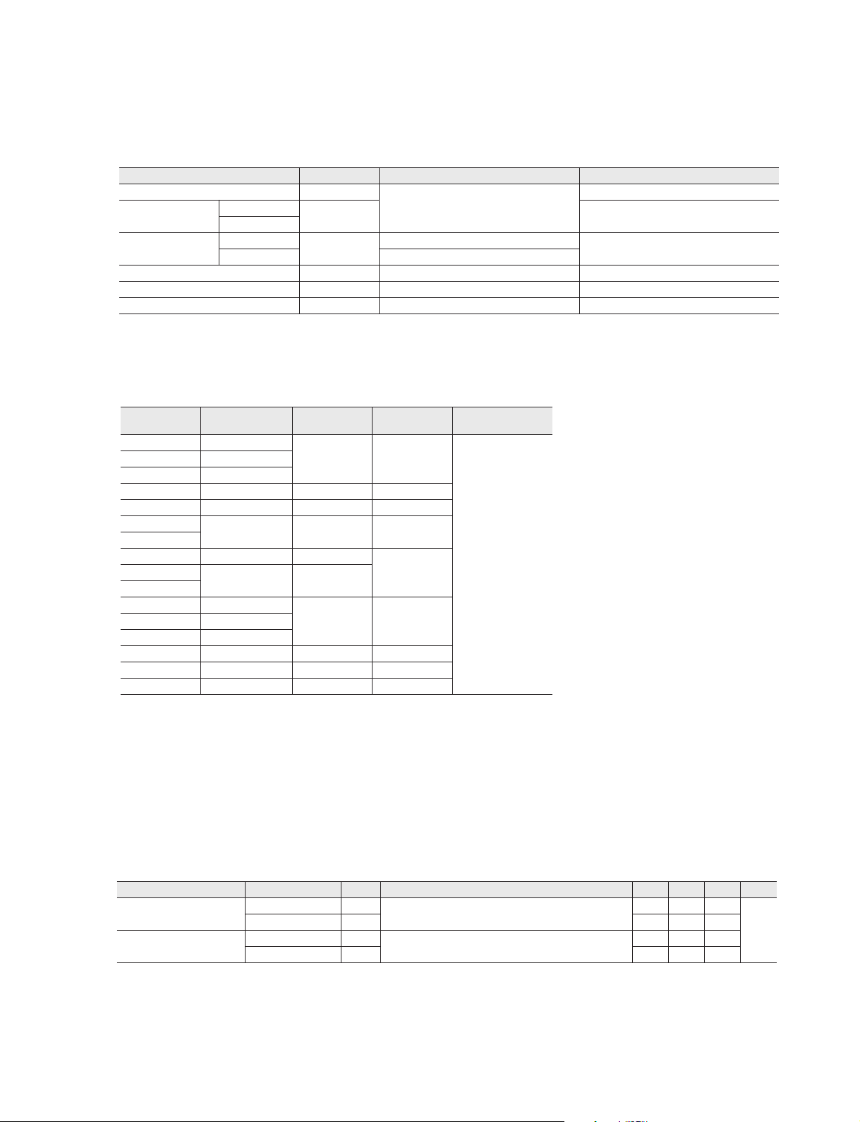
• Control I/O Characteristics
• Frequency Response
Fs= 44.1 kHz or 48 kHz @ 20 Hz–20 kHz, referenced to the nominal output level @1 kHz
Input Output RL Conditions Min. Typ. Max. Unit
INPUT 1-32 <M7CL-32>
INPUT 1-48 <M7CL-48>
OMNI OUT 1-16 600 Ω
GAIN: Max.
–1.5 0.0 0.5
dB
PHONES 8 Ω –3.0 0.0 0.5
ST IN 1-4 [L, R]
OMNI OUT 1-16 600 Ω
GAIN: Max.
–1.5 0.0 0.5
PHONES 8 Ω –3.0 0.0 0.5
All faders are nominal when measured. Output impedance of signal generator: 150ohms
Terminal
ETHERNET ETHERNET
MIDI
WORD CLOCK
REMOTE RS422 D-Sub Connector 9P (Male)
LAMP 1(32ch), 2(48ch) — 0 V – 12 V XLR-4-31 type
USB HOST USB 1.1 — A type USB Connector
*1. 4pin=HOT, 3pin=COLD, Lamp rating 5W, Voltage control by software
IN
OUT
IN
OUT TTL/75 Ω
Format Level Connector
RJ-45
MIDI DIN Connector 5P
—
—
TTL/75 Ω
BNC Connector
*1
• SLOT 1-3 Characteristics
Card Name Function Input Output
MY8-AT ADAT
MY8-TD TASCAM
MY8-AE AES/EBU
MY4-AD ANALOG IN 4 IN —
MY4-DA ANALOG OUT — 4 OUT
MY8-AD24
MY8-AD96
MY8-DA96 ANALOG OUT —
MY8-AE96
MY16-AT ADAT
MY16-TD TASCAM
MY16-C CobraNet ™ 16 IN 16 OUT
MY8-ADDA96 ANALOG I/O 8 IN 8 OUT
MY-16mLAN mLAN 16 IN 16 OUT
ANALOG IN 8 IN —
AES/EBU 8 IN
8 IN 8 OUT
8 OUTMY8-AE96S
16 IN 16 OUTMY16-AE AES/EBU
The Number Of
Usable Cards
3
M7CL-32/M7CL-48
3. Electrical Characteristics
(電気特性)
7

M7CL-32/M7CL-48
• Gain Error
INPUT 1-32 <M7CL-32>
INPUT 1-48 <M7CL-48>
ST IN 1-4 [L, R] OMNI OUT 1-16 600 Ω
Internal OSC
• Total Harmonic Distortion
INPUT 1-32 <M7CL-32>
INPUT 1-48 <M7CL-48>
ST IN 1-4 [L, R] OMNI OUT 1-16 600 Ω
Internal OSC
* Total Harmonic Distortion is measured with a 18 dB/octave filter @ 80kHz
Input Output RL Conditions Min. Typ. Max. Unit
OMNI OUT 1-16 600 Ω
OMNI OUT 1-16 600 Ω Full Scale Output 23.5 24.0 24.5
PHONES 8 Ω –30 dBFs, PHONES Level Control: Max. –0.5 0 0.5
Input
Output RL Conditions Min. Typ. Max. Unit
OMNI OUT 1-16 600 Ω
OMNI OUT 1-16 600 Ω Full Scale Output @1 kHz 0.02
PHONES 8 Ω
• Hum & Noise
Input Output RL Conditions Min. Typ. Max. Unit
INPUT 1-32 <M7CL-32>
INPUT 1-48 <M7CL-48>
All INPUTs <M7CL-32> OMNI OUT 1-16 600 Ω
All INPUTs <M7CL-48> OMNI OUT 1-16 600 Ω
— OMNI OUT 1-16 600 Ω Residual Output Noise, ST Master Off –86
— PHONES 8 Ω Residual Output Noise, PHONES Level Control Min. –86
* Hum & Noise are measured with a 6 dB/octave filter @ 12.7 kHz; equivalent to a 20 kHz filter with infinite dB/octave attenuation.
OMNI OUT 1-16 600Ω
Fs= 44.1 kHz or 48 kHz @1 kHz
Input Level : –62 dBu, GAIN: Max.
Input Level : +10 dBu, GAIN: Min.
Input Level : –62 dBu, GAIN: Max.
Input Level : +10 dBu, GAIN: Min.
2.0 4.0 6.0
2.0 4.0 6.0
Fs= 44.1 kHz or 48 kHz
+4 dBu @20 Hz–20 kHz, GAIN: Max. 0.1
+4 dBu @20 Hz–20 kHz, GAIN: Min. 0.05
+4 dBu @20 Hz–20 kHz, GAIN: Max. 0.1
+4 dBu @20 Hz–20 kHz, GAIN: Min. 0.05
Full Scale Output @1 kHz, PHONES Level Control: Max.
Fs= 44.1 kHz or 48 kHz, EIN= Equivalent Input Noise
Rs= 150 , GAIN: Max.
Master fader at nominal level and
one Ch fader at nominal level. –62
Rs= 150 , GAIN: Min.
Master fader at nominal level and
one Ch fader at nominal level.
Rs= 150 , GAIN: Min.
Master fader at nominal level and all Ch 1-32 in faders at
nominal level.
Rs= 150 , GAIN: Min.
Master fader at nominal level and all Ch 1-48 in faders at
nominal level.
–128
EIN
–84 –79
0.2
–62
–64
dBu
%
dBu
• Dynamic Range
Input Output RL Conditions Min. Typ. Max. Unit
INPUT 1-32 <M7CL-32>
INPUT 1-48 <M7CL-48>
ST IN 1-4 [L, R] OMNI OUT 1-16 600 Ω AD + DA, GAIN: Min. 108
— OMNI OUT 1-16 600 Ω DA Converter 110
* Dynamic range are measured with a 6 dB/octave filter @ 12.7 kHz; equivalent to a 20 kHz filter with infinite dB/octave attenuation.
• Sampling Frequency
External Clock Frequency Range 39.69 50.88
Internal Clock
8
OMNI OUT 1-16 600 Ω AD + DA, GAIN: Min. 108
Parameter Conditions Min. Typ. Max. Unit
Frequency
Accuracy
Jitter
Fs= 44.1 kHz or 48 kHz
Word Clock : Int 44.1 kHz 44.1
Word Clock : Int 48 kHz 48
Word Clock : Int 44.1 kHz
Word Clock : Int 48 kHz
Word Clock : Int 44.1 kHz
Word Clock : Int 48 kHz
dB
kHz
50 ppm
5ns

M7CL-32/M7CL-48
4. Other Functions
(その他機能)
• Libraries
Name Number Total
Scene Memory Preset 1 + User 300 301
Input EQ Library Preset 40 + User 159 199
Output EQ Library Preset 3 + User 196 199
Dynamics Library Preset 41 + User 158 199
Effect Library User 199 199
GEQ Library Preset 1 + User 199 200
• Input Function
Function Parameter
Phase Normal/Reverse
Attenuator –96 to +24 dB
HPF
4 Band Equalizer
Insert Insert Point: Pre EQ/Pre Fader
Direct Out Direct Out Point: Pre HPF/Pre EQ
Dynamics 1
Dynamics 2
Fader Level: 1024 steps, ∞ , –138 dB to +10 dB
On On/Off
DCA Group 8 Groups
Mute Group 8 Groups
Mix Send
Matrix Send
LCR Pan CSR= 0 % to 100 %
Slope= 12 dB/Oct
Frequency= 20 Hz to 600 Hz
Frequency= 20 Hz to 20 kHz
Gain= –18 dB to +18 dB
Q= 0.10 to 10.0
Low Shelving (Low Band)
High Shelving, LPF (High Band)
Type I/Type II
Type: Gate/Ducking/Comp/Expander
Threshold= –54 dB to 0 dB
Ratio= 1:1 to : ∞ 1
Attack= 0 msec to 120 msec
Hold= 0.02 msec to 1.96 sec
Decay= 5 msec to 42.3 sec (Release)
Releace= 5 msec to 42.3 sec
Range= –70 dB to 0 dB
Gain= –18 dB to 0 dB, 0 dB to +18 dB
Knee= Hard to 5 (soft)
Key In: Self Pre EQ/Self Post EQ/Mix Out 13-16
Ch 1-ST IN 4R (8ch block)
Key In Filter: HPF/LPF/BPF
Type: Comp/De-Esser/Compander H/Com-
pander S
Threshold= –54 dB to 0 dB
Ratio= 1:1 to : ∞ 1
Attack= 0 msec to 120 msec
Release= 5 msec to 42.3 sec
Gain= –18 dB to 0 dB, 0 dB to +18 dB
Knee= Hard to 5 (soft)
Key In: Self Pre EQ/Self Post EQ/Mix Out 13-16
Ch 1-ST IN 4R (8ch block)
16 sends
Fix/Variable can be set each two mixes
Mix Send Point: Pre EQ/Pre Fader/Post On
Level: 1024 steps, ∞ , –138 dB to +10 dB
8 Sends
Matrix Send Point: Pre EQ/Pre Fader/Post On
Level: 1024 steps, ∞ , –138 dB to +10 dB
• Output Function
Function Parameter
Attenuator –96 to +24 dB
Frequency= 20 Hz to 20 kHz
Gain= –18 dB to +18 dB
4 Band Equalizer
Insert Insert Point: Pre EQ/Post EQ/Pre Fader/Post On
Dynamics 1
Fader Level: 1024 steps, ∞ , –138 dB to +10 dB
On On/Off
Mute Group 8 Groups
Mix to Matrix
Stereo to Matrix
Oscillator
Q= 0.10 to 10.0
Low Shelving (Low Band)
High Shelving, LPF (High Band)
Type I/Type II
Type: Comp/Expander/Compander H/Compander S
Threshold= –54 dB to 0 dB
Ratio= 1:1 to ∞ :1
Attack= 0 msec to 120 msec
Release= 5 msec to 42.3 sec
Gain= –18 dB to 0 dB, 0 dB to + 18 dB
Knee= Hard to 5 (soft)
Key In: Self Pre EQ/Self Post EQ/Mix Out 13-16
MIX 1-16/MTRX 1-8/ST IN LR/MONO(C)
(8ch block)
Matrix Send Point: Pre Fader/Post On
Level: 1024 steps, ∞ , –138 dB to +10 dB
Level= 0 to –96dB (1 dB step)
On/Off= Software control
Output Port
Function Parameter
Out Port Delay 0 msec to 600 msec
Out Port Phase Normal/Reverse
Attenuator –96 to +24 dB
Processor
Function Parameter
GEQ 31 bands x 4(8) systems
Effects Stereo In/Stereo Out multi effector x 4 systems
9
M7CL-32/M7CL-48
• MBM7CL
Dimensions (W x H x D)
Weight 1.0 kg
Package Contents Cable cover, Owner's Manual
442 x 103 x 36 mm
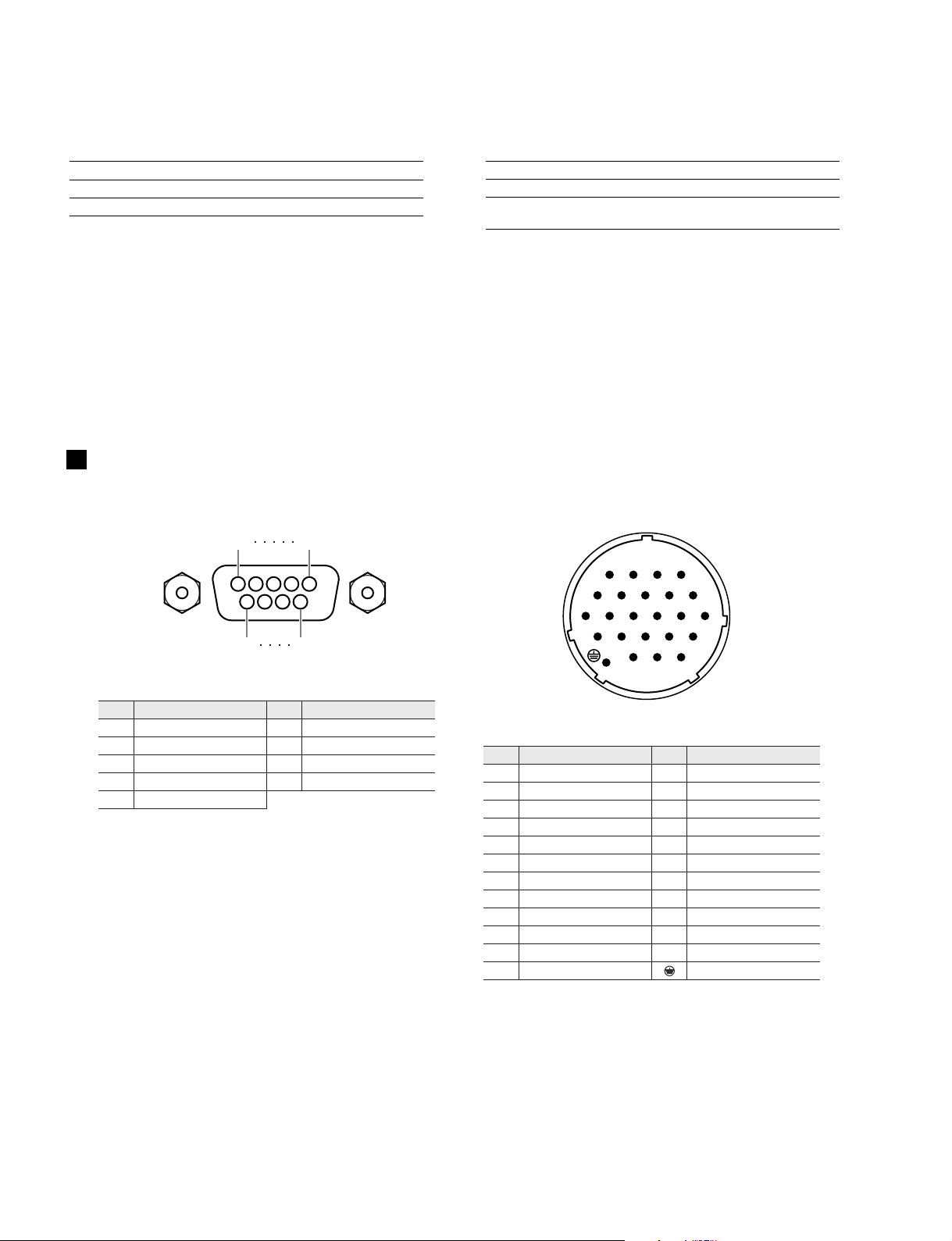
CONNECTOR PIN ASSIGNMENTS
1
6
5
9
寸法 (W x H x D)
質量 1.0 kg
同梱品
442 x 103 x 36 mm
ケーブルカバー 1個、
取扱説明書 1部、保証書 1枚
(コネクターピンアサイン表)
4
3
14
15
23
1
2
6789
5
10111213
16
17181920
21
22
• REMOTE
Pin
1 GND 6 RX+
2 RX– 7 RTS
3 TX– 8 CTS
4 TX+ 9 GND
5 N.C
Signal Name Pin Signal Name
• DC POWER INPUT
Pin Signal Name Pin Signal Name
1 +24V 13 GND
2 +24V 14 GND
3 +24V 15 GND
4 +24V 16 GND
5 +24V 17 GND
6 +24V 18 GND
7 +24V 19 CAUTION(+)
8 +24V 20 CAUTION(–)
9 +24V 21 DETECT A
10 GND 22 DETECT B
11 GND 23 DETECT GND
12 GND Frame GND
10
M7CL-32/M7CL-48
q q
w
e
r t
y
u
i
!0
o
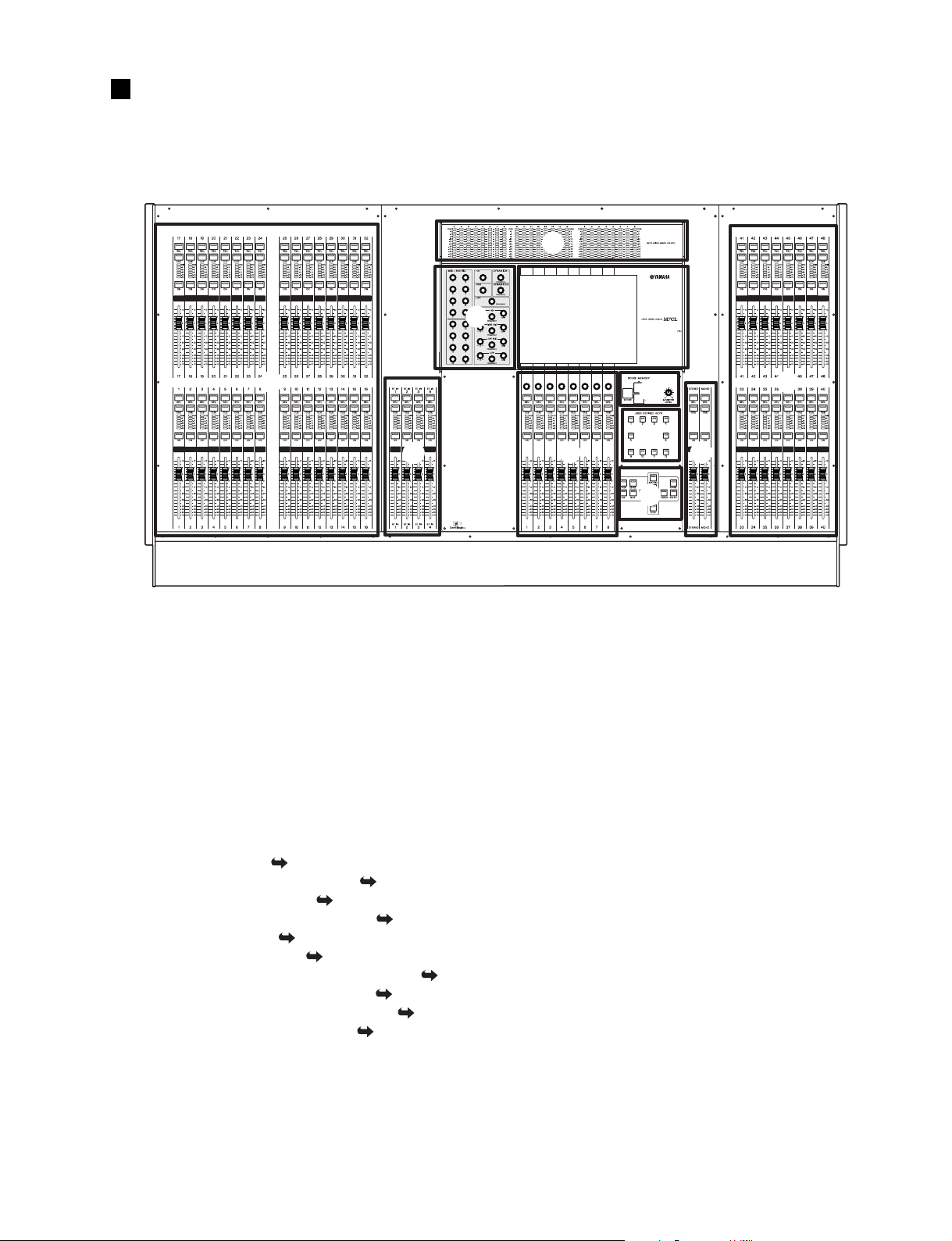
PANEL LAYOUT
1. Top Panel
(トップパネル)
(パネルレイアウト)
* This illustration shows the top panel of the M7CL-48. The M7CL-32
does not have the INPUT section at the right (channels 33–48).
※このイラストは M7CL-48のトップパネルです。M7CL-32には右側の
INPUTセクション(チャンネル 33〜48)がありません。
q INPUT section: ( P.13)
w ST IN (Stereo Input) section: (
e Meter bridge (option): (
r SELECTED CHANNEL section: (
t Display section: (
y Centralogic section: (
u SCENE MEMORY / MONITOR section: (
i USER DEFINED KEYS section: (
o STEREO/MONO MASTER section: (
!0 NAVIGATION KEYS section: (
P.14)
P.15)
P.13)
P.13)
P.16)
P.14)
P.16)
P.16)
P.15)
q インプットセクション
w ステレオインプットセクション
e メーターブリッジ(オプション)
r セレクテッドチャンネルセクション
t ディスプレイセクション
y セントラロジックセクション
u シーンメモリー / モニターセクション
i ユーザー定義キーセクション
o ステレオ / モノマスターセクション
!0 ナビゲーションキーセクション
11
M7CL-32/M7CL-48
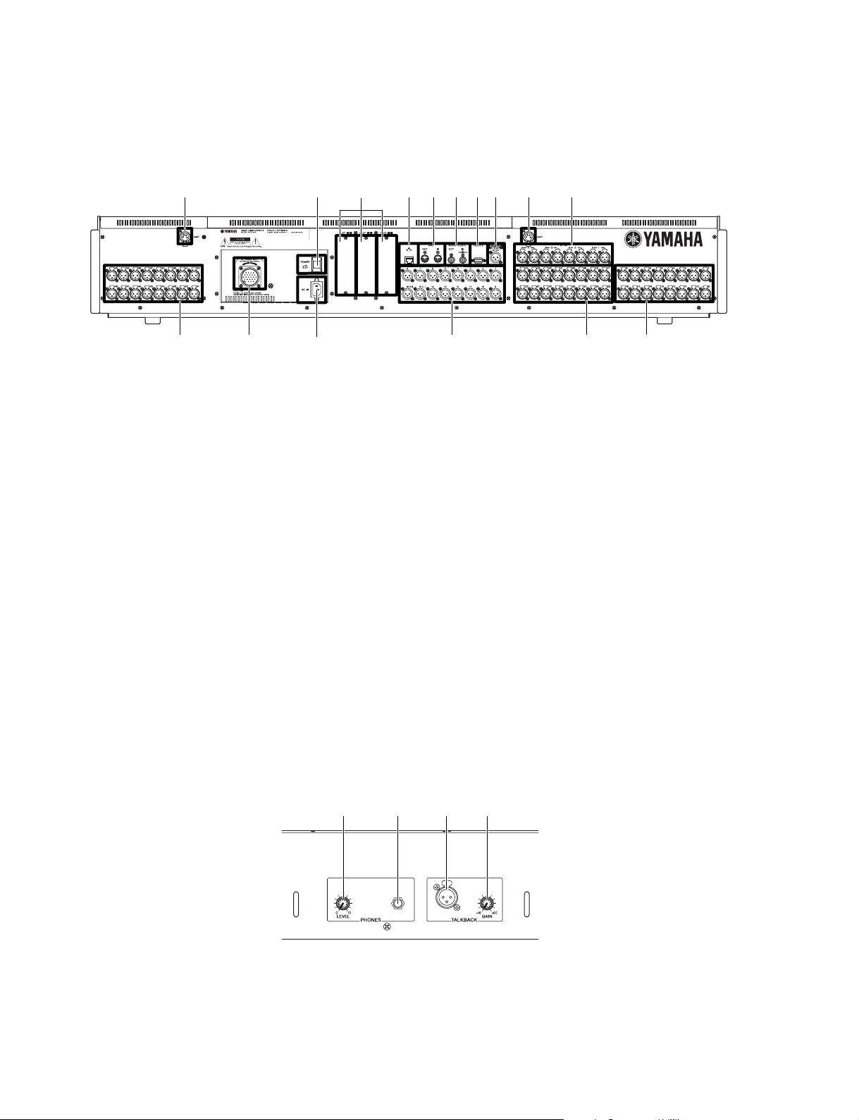
2. Rear Panel
(リアパネル)
M7CL-48 only
eoiuytew
qr
M7CL-48 only
q INPUT jacks 1-32 (M7CL-32)
INPUT jacks 1-48 (M7CL-48)
w ST IN jacks 1-4
e LAMP connector
r OMNI OUT jacks 1-16
t 2TR OUT DIGITAL jack
y REMOTE connector
u WORD CLOCK IN/OUT connectors
i MIDI IN/OUT connectors
o ETHERNET connector
!0 Slots 1-3
!1 AC IN connector
!2 POWER switch
!3 DC POWER INPUT connector
!2!3
!0!1
q
* This illustration shows the rear panel of the M7CL-48.
※このイラストは M7CL-48のリアパネルです。
q INPUT端子 1 〜32(M7CL-32)
INPUT端子1 〜 48(M7CL-48)
w STIN端子 1 〜 4
e LAMP端子
r OMNIOUT端子 1〜 16
t2TROUTDIGITAL端子
y REMOTE端子
u WORDCLOCKIN/OUT端子
i MIDIIN/OUT端子
oETHERNET端子
!0スロット 1〜 3
!1ACIN端子
!2POWERスイッチ
!3DCPOWERINPUT端子
q
3. Under the front pad
12
(フロントパッド下)
qwer
q PHONES LEVEL knob
w PHONES OUT (headphone output) jack
e TALKBACK jack
r TALKBACK GAIN knob
q PHONESLEVELノブ
w PHONESOUT(ヘッドフォン出力)端子
e TALKBACK端子
r TALKBACKGAINノブ
M7CL-32/M7CL-48
q
w
e
r
t
q
w
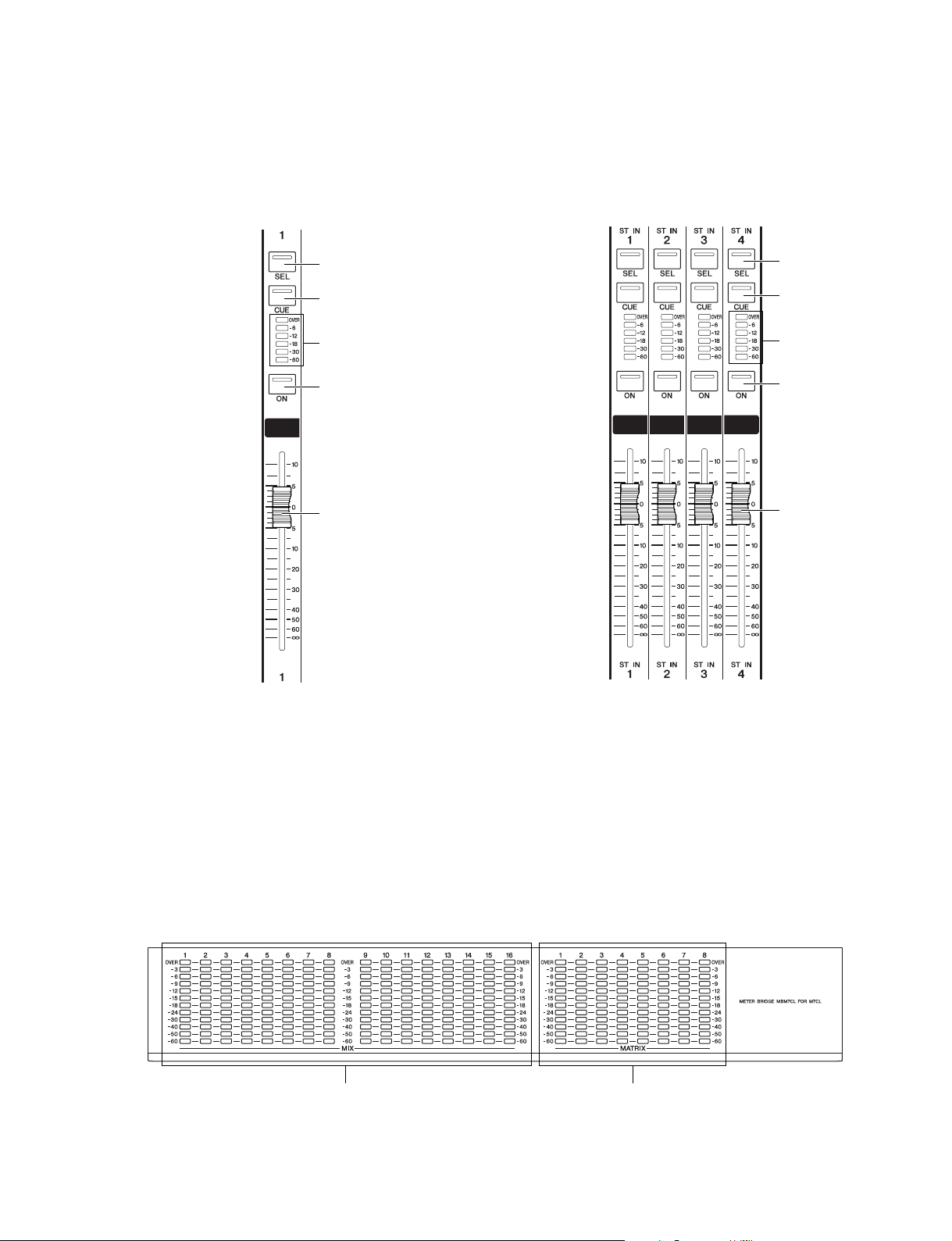
4. Top Panel Details
(トップパネル詳細)
4-1 INPUT section
(インプットセクション)
4-2 ST IN (Stereo Input) section
(ステレオインプットセクション)
q
w
e
r
t
4-3 Meter bridge (option)
q [SEL] key
w [CUE] key
e Meter LEDs
r [ON] key
t Fader
q [SEL]キー
w [CUE]キー
e メーター LED
r [ON]キー
t フェーダー
(メーターブリッジ(オプション))
q MIX meters
w MATRIX meters
q MIXメーター
w MATRIXメーター
13
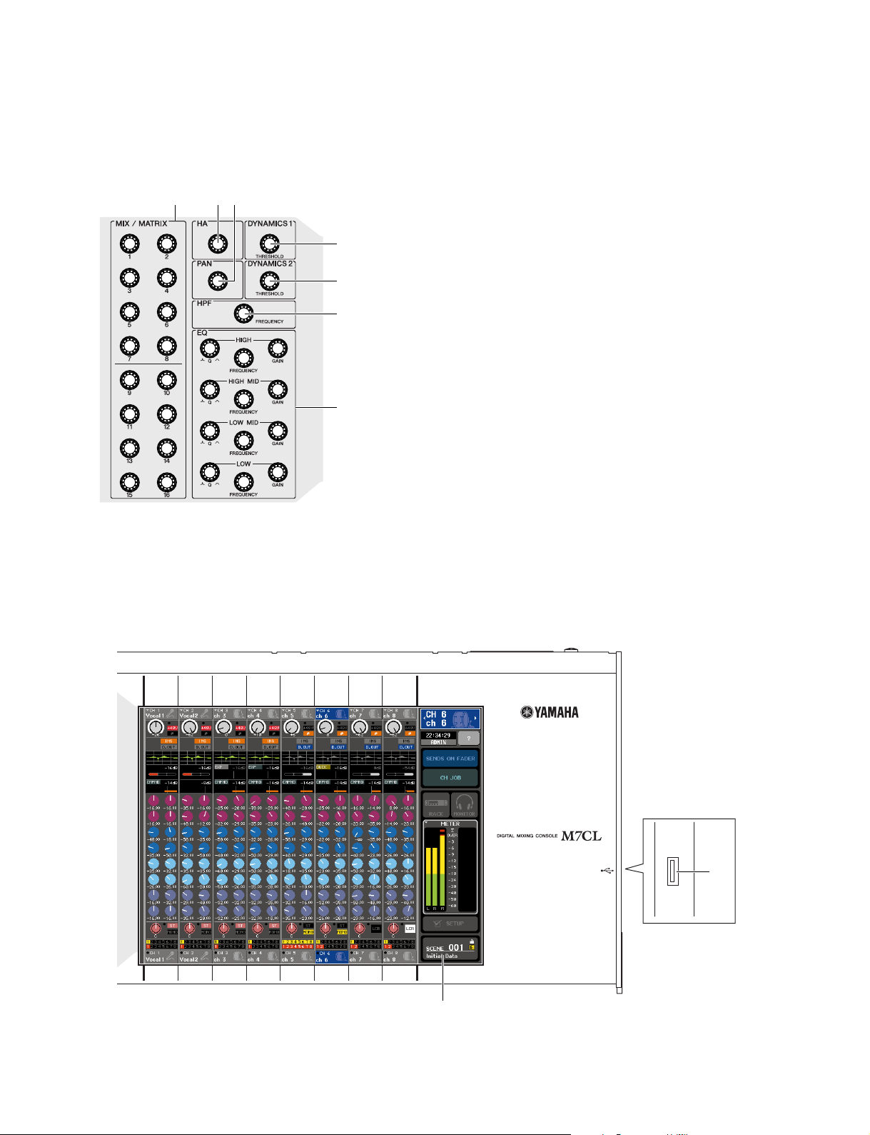
M7CL-32/M7CL-48
4-4 SELECTED CHANNEL section
qw
e
(セレクテッドチャンネルセクション)
r
t
y
u
q [MIX/MATRIX] encoders
w [HA] encoder
e [PAN] encoder
r [DYNAMICS 1] encoder
t [DYNAMICS 2] encoder
y [HPF] encoder
u EQ [Q], EQ [FREQUENCY],
EQ [GAIN] encoders
q [MIX/MATRIX]エンコーダー)
w [HA]エンコーダー)
e [PAN]エンコーダー)
r [DYNAMICS1]エンコーダー)
t [DYNAMICS2]エンコーダー)
y [HPF]エンコーダー)
u EQ[Q]、EQ[FREQUENCY]、
EQ[GAIN]エンコーダー)
4-5 Display section
(ディスプレイセクション)
q Display (touch screen)
w USB connector
q ディスプレイ(タッチスクリーン)
w USB端子
w
q
14
M7CL-32/M7CL-48
q
r
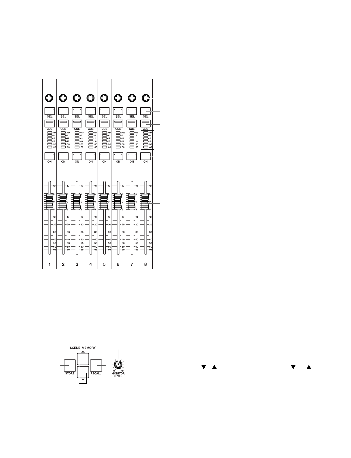
4-6 Centralogic section
(セントラロジックセクション)
q
w
e
r
t
y
q Multi-function encoders
w [SEL] key
e [CUE] key
r Meter LEDs
t [ON] key
y Fader
q マルチファンクションエンコーダー
w [SEL]キー
e [CUE]キー
r メーター LED
t [ON]キー
y フェーダー
4-7 SCENE MEMORY/MONITOR section
w
q SCENE MEMORY [STORE] key
w SCENE MEMORY [RECALL] key
e SCENE MEMORY [
r [MONITOR LEVEL] knob
e
(シーンメモリー/モニターセクション)
q SCENEMEMORY[STORE]キー
w SCENEMEMORY[RECALL]キー
]
/
e SCENEMEMORY[
keys
r [MONITORLEVEL]ノブ
]/[
]キー
15
M7CL-32/M7CL-48
u
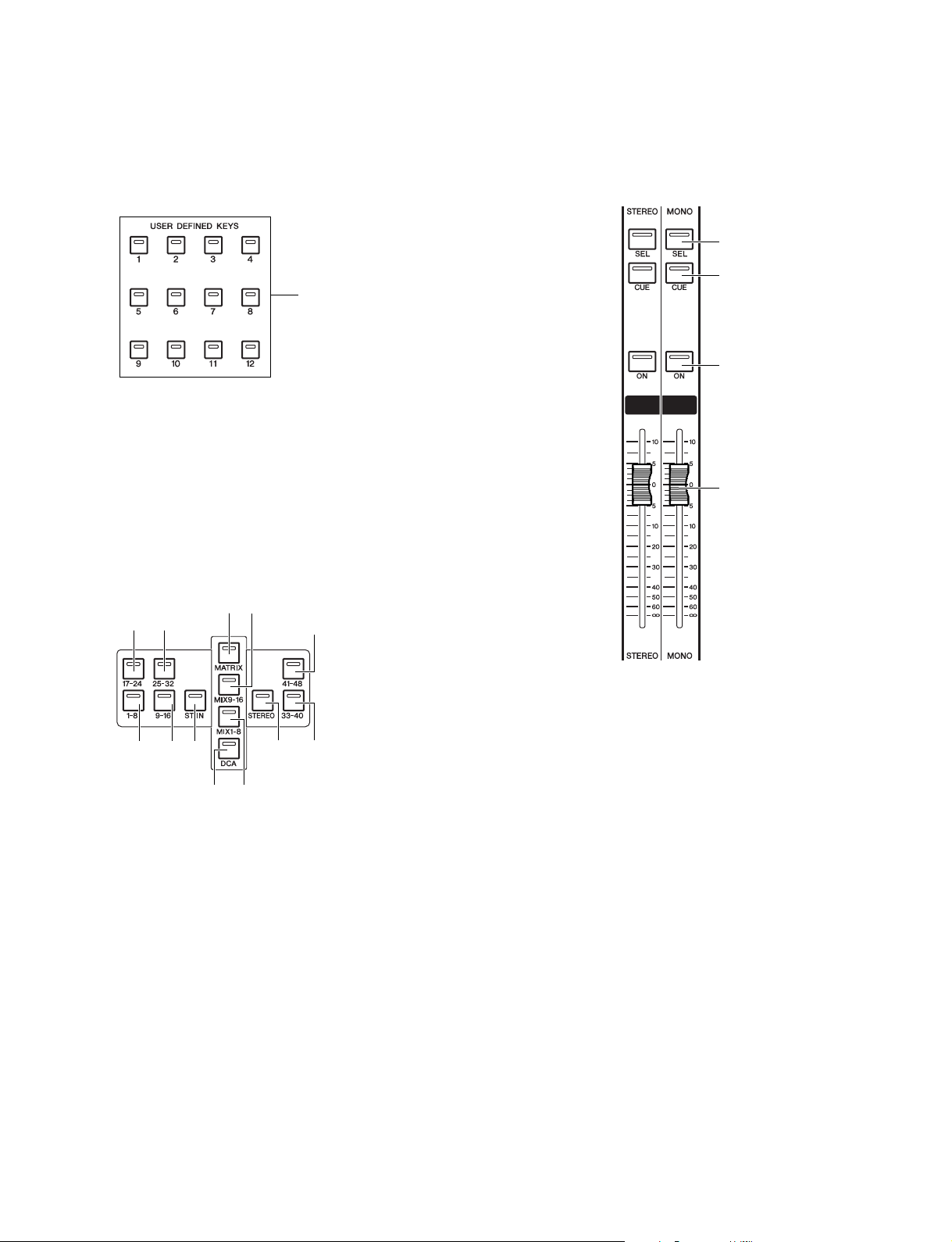
4-8 USER DEFINED KEYS section
(ユーザー定義キーセクション)
q
q User defined keys [1]-[12]
q ユーザー定義キー[1]〜[12]
4-10 NAVIGATION KEYS section
(ナビゲーションキーセクション)
o
i
r
e
!2
4-9 STEREO/MONO MASTER section
(ステレオ/ モノマスターセクション)
q
w
e
r
q
w
t
y
q [IN 1-8] key
w [IN 9-16] key
e [IN 17-24] key
r [IN 25-32] key
t [ST IN] key
y [DCA] key
u [MIX 1-8] key
i [MIX 9-16] key
o [MATRIX] key
!0 [STEREO] key
!1 [IN 33-40] key {M7CL-48 only}
!2 [IN 41-48] key {M7CL-48 only}
!0
!1
q [IN1‐8]キー
w [IN9‐16]キー
e [IN17‐24]キー
r [IN25‐32]キー
t [STIN]キー
y [DCA]キー
u [MIX1‐8]キー
i [MIX9‐16]キー
o [MATRIX]キー
!0 [STEREO]キー
!1 [IN33‐40]キー(M7CL‐48のみ)
!2 [IN41‐48]キー(M7CL‐48のみ)
q [SEL] key
w [CUE] key
e [ON] key
r Fader
q [SEL]キー
w [CUE]キー
e [ON]キー
r フェーダー
16
M7CL-32/M7CL-48
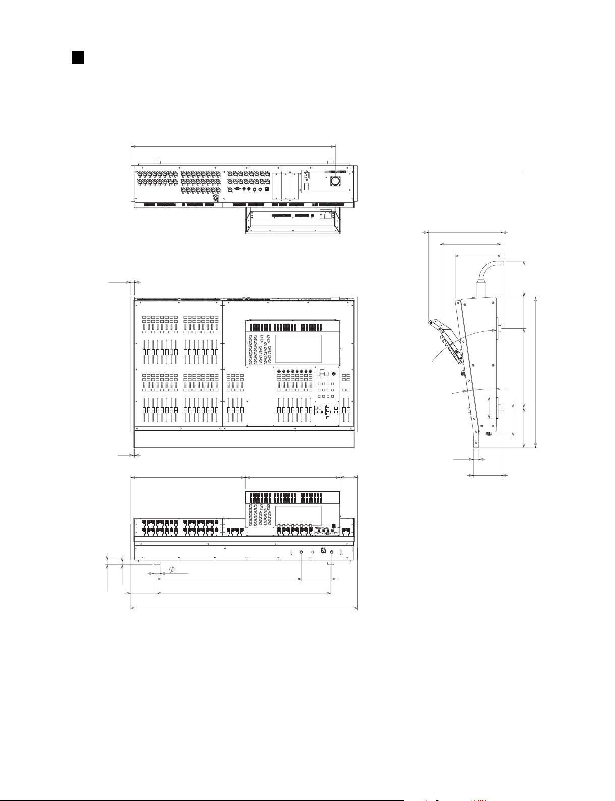
DIMENSIONS
• M7CL-32
18
(寸法図)
955: PSL360 (option)
340:MBM7CL (option)
286
216
168: PSL360 (option)
146
22
4
13
124
30
535
672
812
1060
442
144
83
35˚
8˚
25
102
130
Units: mm
(単位)
111
370
185
701
17
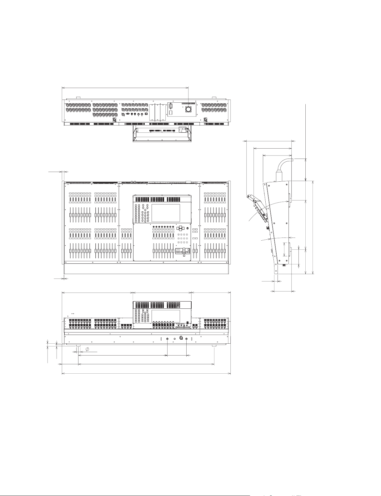
M7CL-32/M7CL-48
• M7CL-48
18
955: PSL360 (option)
340:MBM7CL (option)
286
216
168: PSL360 (option)
146
22
4
13
124
30
535
672
1026
1274
442
144
297
35˚
8˚
25
102
130
Units: mm
(単位)
111
370
185
701
18
M7CL-32/M7CL-48
Bottom assembly 32:
See page 20.
Control panel 2 assembly:
See page 22.
Control panel 1 assembly 32:
See page 22.
LCD assembly 32:
See page 23.
(コンパネ2Ass'y)
(コンパネ1Ass'y32)
(LCDAss'y32)
(ボトムAss'y32)
CIRCUIT BOARD LAYOUT
M7CL-32
(ユニットレイアウト)
M7CL-48
Control panel 2 assembly:
(コンパネ2Ass'y)
See page 22.
Control panel 1 assembly 48:
(コンパネ1Ass'y48)
See page 22.
LCD assembly 48:
(LCDAss'y48)
See page 23.
Control panel 3 assembly :
(コンパネ3Ass'y)
See page 23.
(ボトムAss'y48)
Bottom assembly 48:
See page 21.
19
M7CL-32/M7CL-48
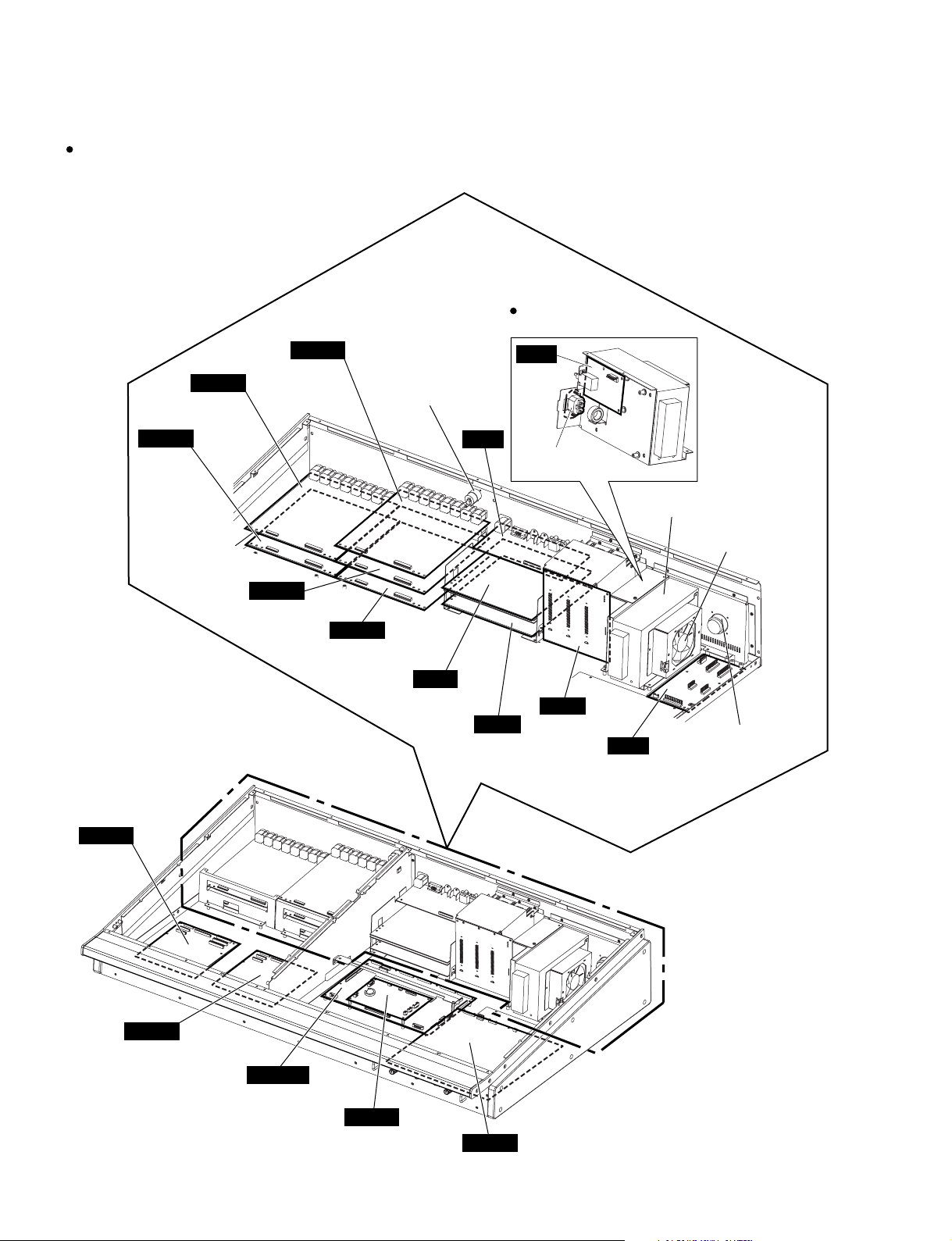
M7CL-32
Bottom assembly 32
HAAD
INPUT
CH 9-16
HAAD
INPUT
CH 1-8
(ボトムAssy32)
HAAD
ST IN
CH 1-4
Cannon connector
(キャノンコネクタ)
Power supply assembly
(電源Ass'y)
AC
JK
AC inlet
(ACインレット)
Power supply unit
(電源ユニット)
DC fan motor
(DCファンモーター)
DCIN
CH 1-8
CH 9-16
DCIN
CH 17-24
CH 25-32
HAAD
INPUT CH 17-24
INPUT CH 25-32
DSP32
HAAD
DA
OMNI OUT
CH 1-8
DA
OMNI OUT
CH 9-16
OPT
DC
Receptacle assembly
(レセプタクルAss'y)
20
CPUM
DCMS
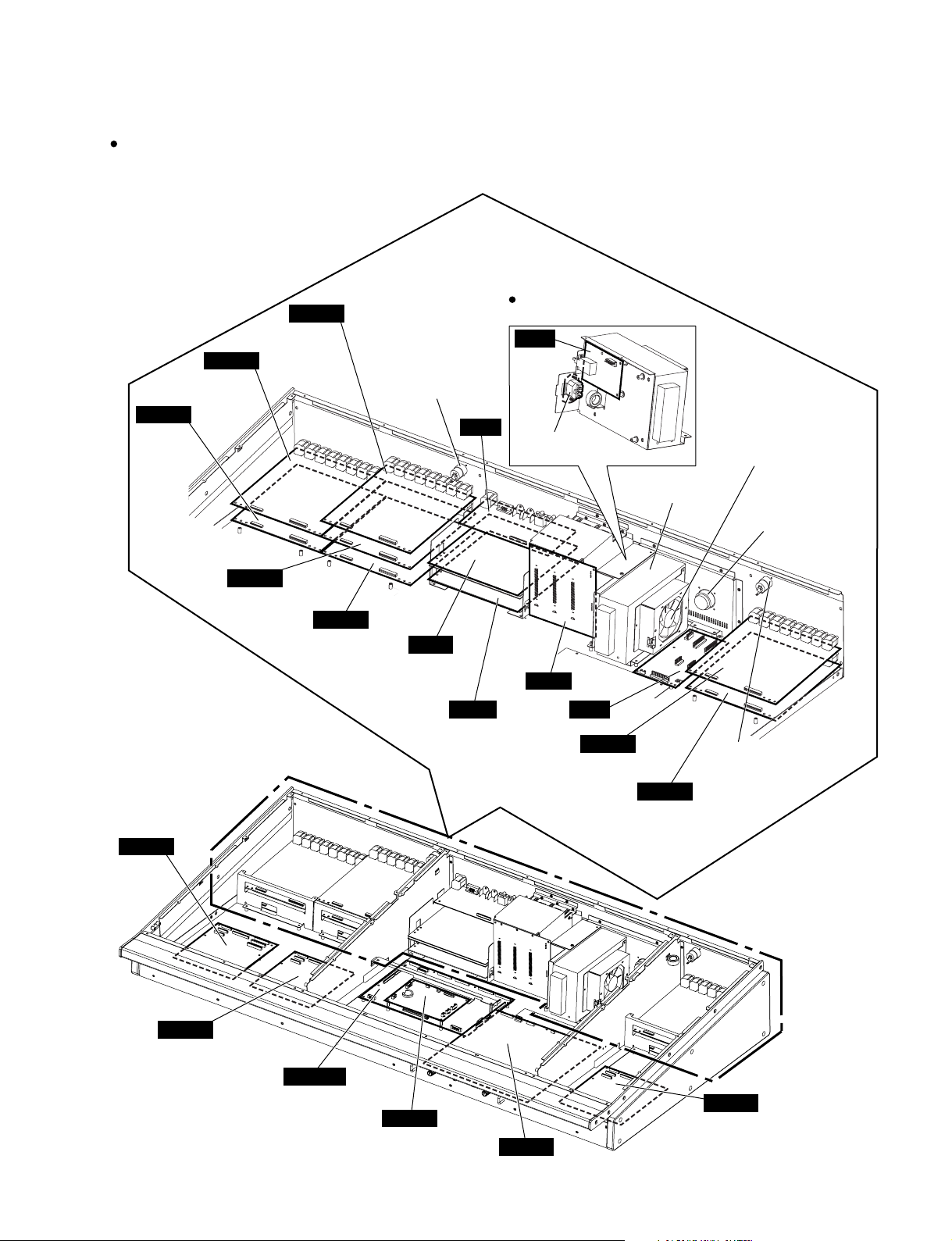
CPUM
DSP48
DCMS
(ACインレット)
AC
AC inlet
HAAD
INPUT
CH 1-8
HAAD
INPUT
CH 9-16
HAAD
INPUT CH 25-32
DA
OMNI OUT
CH 1-8
DA
OMNI OUT
CH 9-16
OPT
DC
JK
Cannon connector
(キャノンコネクタ)
Cannon connector
(キャノンコネクタ)
Power supply unit
(電源ユニット)
DC fan motor
(DCファンモーター)
Power supply assembly
(電源Ass'y)
Receptacle assembly
(レセプタクルAss'y)
DCIN
CH 17-24
CH 25-32
DCIN
CH 1-8
CH 9-16
DCIN
CH 33-40
CH 41-48
HAAD
INPUT CH 33-40
HAAD
INPUT CH 41-48
HAAD
INPUT CH 17-24
HAAD
ST IN
CH 1-4
M7CL-48
Bottom assembly 48
M7CL-32/M7CL-48
(ボトムAssy48)
21
M7CL-32/M7CL-48
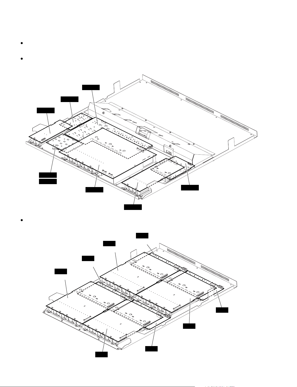
M7CL-32
Control panel 1 assembly 32
M7CL-48
Control panel 1 assembly 48
<Bottom view>
PNMS2
FDMS2
(コンパネ1Assy32)
(コンパネ1Assy48)
PNMS8
NAV32
NAV48
Control panel 2 assembly
<Bottom view>
(M7CL-32)
(M7CL-48)
PNIN
CH 9-16
FDIN
CH 9-16
FDMS8
FDMS4
(コンパネ2Assy)
FDIN
CH 25-32
PNMS4
PNIN
CH 25-32
PNIN
CH 17-24
22
FDIN
CH 1-8
FDIN
CH 17-24
PNIN
CH 1-8
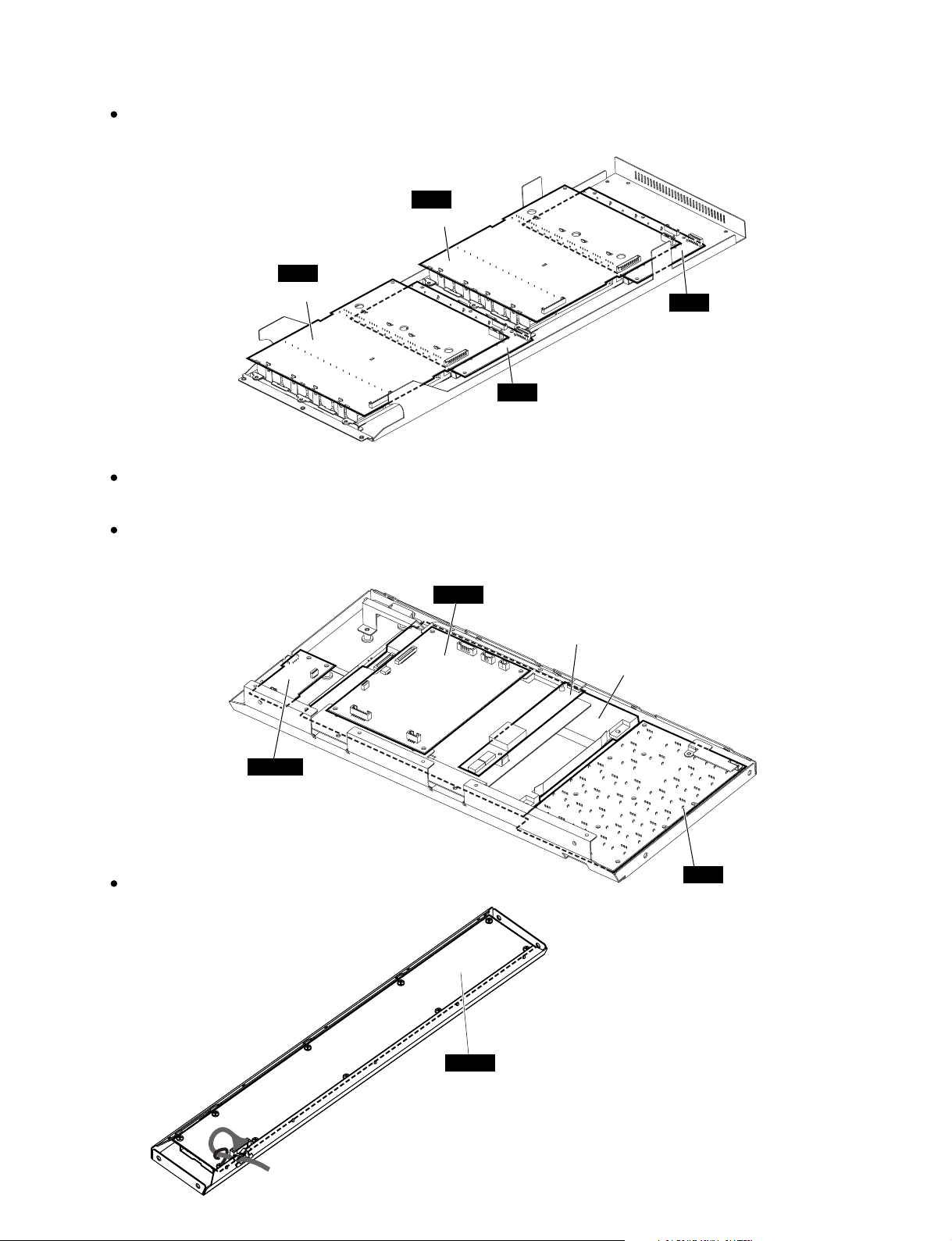
Control panel 3 assembly (M7CL-48 only)
(コンパネ 3Assy(M7CL-48のみ))
M7CL-32/M7CL-48
<Bottom view>
M7CL-32
LCD assembly 32
M7CL-48
LCD assembly 48
<Bottom view>
CH 41-48
FDIN
CH 33-40
(LCDAssy32)
(LCDAssy48)
FDIN
PNIN
CH 41-48
PNIN
CH 33-40
CPUP
DC-AC inverter
(DC-ACインバータ)
Touch panel assembly
(TPAss'y)
MBM7CL (Option)
<Bottom view>
USBIF
ENC
MB
23
M7CL-32/M7CL-48
■ DISASSEMBLY PROCEDURE
Precautions(注意事項)
Note: Take care not to trap your fingers.
* Install the filament tape and the harness clamp in the
same way as they were before removal.
* After replacing the FDMS2, FDMS4, FDMS8 and FDIN
circuit boards, be sure to calibrate the faders. (See
page 192.)
* MAC (Media Access Control) address is stored in the
CPUM circuit board assembly. If the CPUM circuit
board assembly is replaced, MAC address will be
changed.
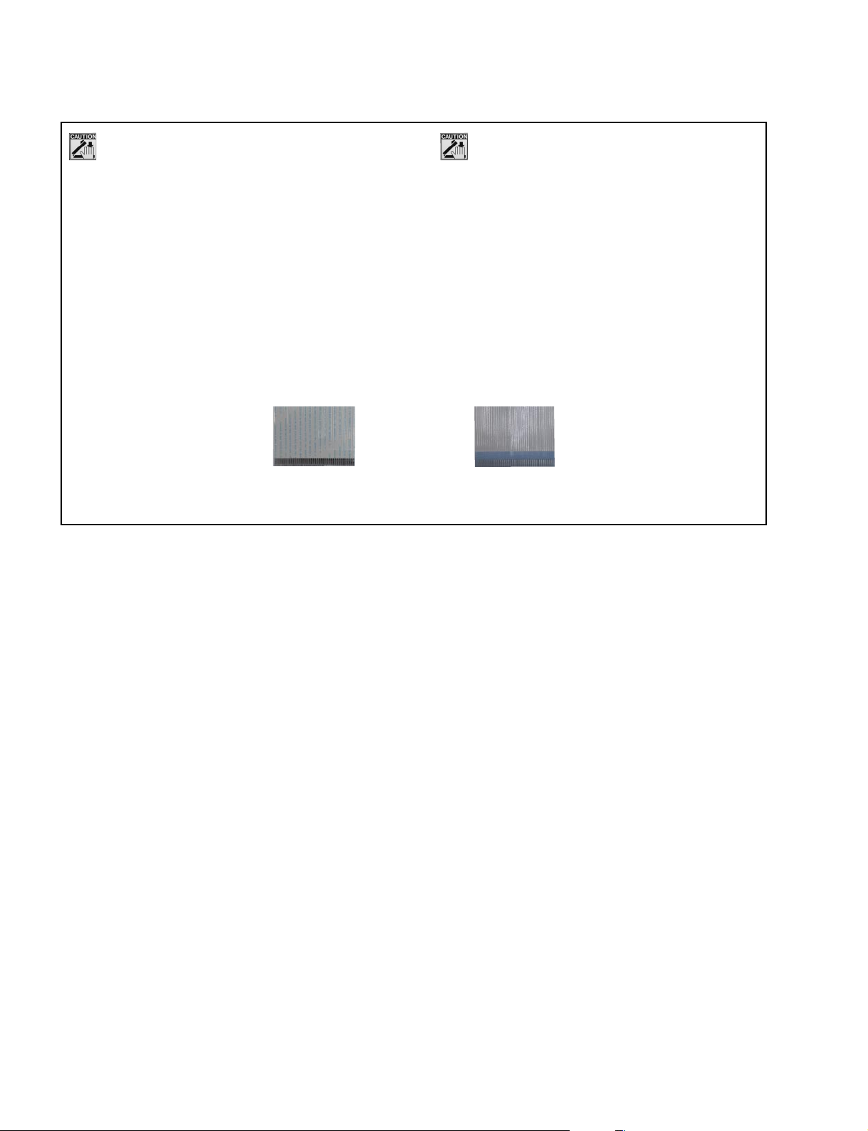
* Notes on Flat Cable
Contacts are visible from the back. Pay attention not
to insert and install the cable to the connector
inversely. (Photo 1)
Front Side (Printed Side)
(表面(印刷面))
(分解手順)
注意:作業中は指を挟 まない様に注意してください。
※ フィラメントテープ、束線止めは、取り外す前と同じよう
に取り付けてください。
※ FDMS2シート、FDMS4シート、FDMS8シート、FDINシー
トを交換後は、フェーダーのキャリブレーションを実施し
てください。(195ページ参照)
※ CPUMシートAss'yには、MAC(MediaAccessControl)アド
レスが設定されています。CPUMシートAss'yを交換する
と、MACアドレスが変更されます。
※ フラットケーブルの注意
接点が裏面から透けて見えます。コネクタにケーブルの
表・裏を逆に差込まないように注意して取り付けてくださ
い。(写真1)
Back Side(裏面)
Photo 1 (写真1)
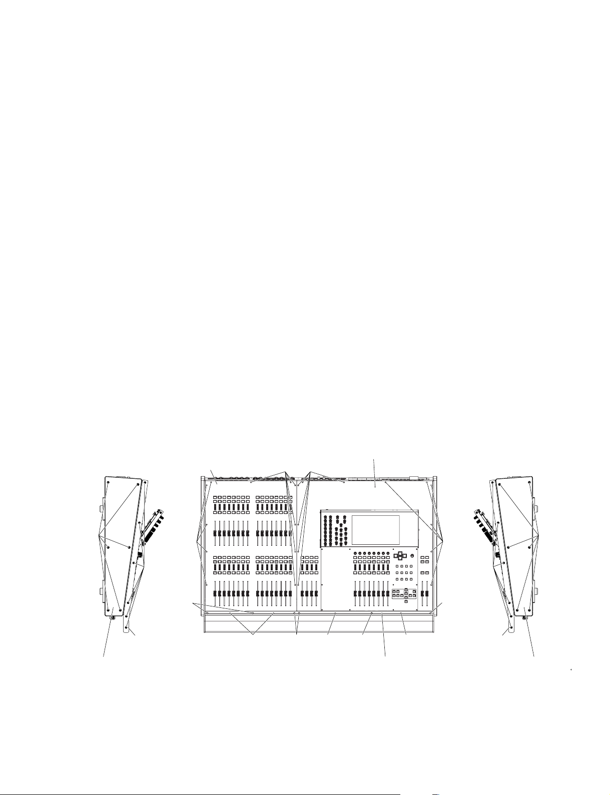
1. Front Plate 32 (M7CL-32), Front Plate 48 (M7CL-48)(フロントプレート32(M7CL-32)、フロントプレート48(M7CL-48)) . . . . . . 25
2. Control Panel 1 Assembly 32 (M7CL-32), Control Panel 1 Assembly 48 (M7CL-48)
(コンパネ1Ass'y32(M7CL-32)、コンパネ1Ass'y48(M7CL-48)) . . . . . . . . . . . . . . . . . . . . . . . . . . . . . . . . . . . . . . . . . . . . . . . . . . 27
3. Control Panel 2 Assembly(コンパネ2Ass'y) . . . . . . . . . . . . . . . . . . . . . . . . . . . . . . . . . . . . . . . . . . . . . . . . . . . . . . . . . . . . . . . . . . 27
4. Control Panel 3 Assembly (M7CL-48 only)(コンパネ3Ass'y(M7CL-48のみ)) . . . . . . . . . . . . . . . . . . . . . . . . . . . . . . . . . . . . . . . . 28
5. Side Pad L, R(サイドアルミパッドL、R) . . . . . . . . . . . . . . . . . . . . . . . . . . . . . . . . . . . . . . . . . . . . . . . . . . . . . . . . . . . . . . . . . . . . . . . 28
6. Front Pad Assembly 32 (M7CL-32), Front Pad Assembly 48 (M7CL-48)
(FパッドAss'y32(M7CL-32)、FパッドAss'y48(M7CL-48)) . . . . . . . . . . . . . . . . . . . . . . . . . . . . . . . . . . . . . . . . . . . . . . . . . . . . . . . 28
7. Wood Panel L, R(ウッドパネルL、R) . . . . . . . . . . . . . . . . . . . . . . . . . . . . . . . . . . . . . . . . . . . . . . . . . . . . . . . . . . . . . . . . . . . . . . . . . 29
A. Disassembly Procedure of Bottom Assembly section underneath Control Panel 1 Assembly
(コンパネ1Ass'y下のボトムAss'y部の分解)
A-1. CPUM Circuit Board Assembly(CPUMシートAss'y) . . . . . . . . . . . . . . . . . . . . . . . . . . . . . . . . . . . . . . . . . . . . . . . . . . . . . . . . . . . . 30
A-2. Replacing the Lithium Battery(リチウム電池の交換) . . . . . . . . . . . . . . . . . . . . . . . . . . . . . . . . . . . . . . . . . . . . . . . . . . . . . . . . . . . . 31
A-3. DSP32 Circuit Board (M7CL-32), DSP48 Circuit Board (M7CL-48)(DSP32シート(M7CL-32)、DSP48シート(M7CL-48)) . . . . . 31
A-4. JK Circuit Board(JKシート) . . . . . . . . . . . . . . . . . . . . . . . . . . . . . . . . . . . . . . . . . . . . . . . . . . . . . . . . . . . . . . . . . . . . . . . . . . . . . . . . 31
A-5. DA (1/2, 2/2) Circuit Boards(DA(1/2、2/2)シート) . . . . . . . . . . . . . . . . . . . . . . . . . . . . . . . . . . . . . . . . . . . . . . . . . . . . . . . . . . . . . . . 32
A-6. OPT Circuit Board(OPTシート) . . . . . . . . . . . . . . . . . . . . . . . . . . . . . . . . . . . . . . . . . . . . . . . . . . . . . . . . . . . . . . . . . . . . . . . . . . . . . 32
A-7. DC Circuit Board(DCシート) . . . . . . . . . . . . . . . . . . . . . . . . . . . . . . . . . . . . . . . . . . . . . . . . . . . . . . . . . . . . . . . . . . . . . . . . . . . . . . . 32
A-8. Receptacle Assembly(レセプタクルAss'y) . . . . . . . . . . . . . . . . . . . . . . . . . . . . . . . . . . . . . . . . . . . . . . . . . . . . . . . . . . . . . . . . . . . . 33
A-9. Power Supply Assembly(電源Ass'y) . . . . . . . . . . . . . . . . . . . . . . . . . . . . . . . . . . . . . . . . . . . . . . . . . . . . . . . . . . . . . . . . . . . . . . . . . 33
A-10. AC Circuit Board, AC Inlet Assembly, DC Fan Motor, Power Supply Unit
(ACシート、インレットAss'y、DCファンモーター、電源ユニット) . . . . . . . . . . . . . . . . . . . . . . . . . . . . . . . . . . . . . . . . . . . . . . . . . . . 33
A-11. DCMS Circuit Board(DCMSシート) . . . . . . . . . . . . . . . . . . . . . . . . . . . . . . . . . . . . . . . . . . . . . . . . . . . . . . . . . . . . . . . . . . . . . . . . . 35
B. Disassembly Procedure of Bottom Assembly section underneath Control Panel 2 Assembly
(コンパネ2Ass'y下のボトムAss'y部の分解)
B-1. Cannon Connector(キャノンコネクタ) . . . . . . . . . . . . . . . . . . . . . . . . . . . . . . . . . . . . . . . . . . . . . . . . . . . . . . . . . . . . . . . . . . . . . . . 36
B-2. HAAD (1/5~5/5) Circuit Boards(HAAD(1/5〜5/5)シート) . . . . . . . . . . . . . . . . . . . . . . . . . . . . . . . . . . . . . . . . . . . . . . . . . . . . . . . . 36
B-3. DCIN (1/2, 2/2) Circuit Boards(DCIN(1/2、2/2)シート) . . . . . . . . . . . . . . . . . . . . . . . . . . . . . . . . . . . . . . . . . . . . . . . . . . . . . . . . . . . 38
C. Disassembly Procedure of Bottom Assembly section underneath Control Panel 3 Assembly (M7CL-48 only)
(コンパネ3Ass'y下のボトムAss'y部の分解(M7CL-48のみ))
C-1. Cannon Connector(キャノンコネクタ) . . . . . . . . . . . . . . . . . . . . . . . . . . . . . . . . . . . . . . . . . . . . . . . . . . . . . . . . . . . . . . . . . . . . . . . 38
C-2. HAAD (1/2, 2/2) Circuit Boards(HAAD(1/2、2/2)シート) . . . . . . . . . . . . . . . . . . . . . . . . . . . . . . . . . . . . . . . . . . . . . . . . . . . . . . . . . 38
C-3. DCIN Circuit Board(DCINシート) . . . . . . . . . . . . . . . . . . . . . . . . . . . . . . . . . . . . . . . . . . . . . . . . . . . . . . . . . . . . . . . . . . . . . . . . . . . 40
D. Disassembly Procedure of Control Panel 1 Assembly(コンパネ1Ass'yの分解)
D-1. Removing the MBM7CL (Option)(MBM7CL(オプション)の取り外し) . . . . . . . . . . . . . . . . . . . . . . . . . . . . . . . . . . . . . . . . . . . . . . 40
D-2. LCD Assembly(LCDAss'y) . . . . . . . . . . . . . . . . . . . . . . . . . . . . . . . . . . . . . . . . . . . . . . . . . . . . . . . . . . . . . . . . . . . . . . . . . . . . . . . . 42
24
M7CL-32/M7CL-48
[22A] [12A]
[22A]
[52A]
[22A]
<Left side view> <Top view>
[1370A]
[1320A]
Side pad L
(サイドアルミパッドL)
Wood panel L
(ウッドパネルL)
Control panel 2 assembly
(コンパネ2 Ass'y)
Control panel 1 assembly 32
(コンパネ1 Ass'y 32)
<Right side view>
[1370B]
[1320B]
Side pad R
(サイドアルミパッドR)
Wood panel R
(ウッドパネルR)
Front plate 32
(フロントプレート32)
[12A]
[12A] [12A][52A][52A]
[52A]
D-3. FDMS2 Circuit Board, FDMS4 Circuit Board, FDMS8 Circuit Board(FDMS2シート、FDMS4シート、FDMS8シート) . . . . . . . . . 42
D-4. PNMS2 Circuit Board(PNMS2シート) . . . . . . . . . . . . . . . . . . . . . . . . . . . . . . . . . . . . . . . . . . . . . . . . . . . . . . . . . . . . . . . . . . . . . . . . 42
D-5. PNMS4 Circuit Board(PNMS4シート) . . . . . . . . . . . . . . . . . . . . . . . . . . . . . . . . . . . . . . . . . . . . . . . . . . . . . . . . . . . . . . . . . . . . . . . . 42
D-6. NAV32+PNMS8 Circuit Board (M7CL-32), NAV48+PNMS8 Circuit Board (M7CL-48)
(NAV32+PNMS8シート(M7CL-32)、NAV48+PNMS8シート(M7CL-48)) . . . . . . . . . . . . . . . . . . . . . . . . . . . . . . . . . . . . . . . . . . . . . 43
E. Disassembly Procedure of Control Panel 2 Assembly(コンパネ2Ass'yの分解)
E-1. FDIN (1/4~4/4) Circuit Boards(FDIN(1/4〜4/4)シート) . . . . . . . . . . . . . . . . . . . . . . . . . . . . . . . . . . . . . . . . . . . . . . . . . . . . . . . . . . 44
E-2. PNIN (1/4~4/4) Circuit Boards(PNIN(1/4〜4/4)シート) . . . . . . . . . . . . . . . . . . . . . . . . . . . . . . . . . . . . . . . . . . . . . . . . . . . . . . . . . . 46
F. Disassembly Procedure of Control Panel 3 Assembly (M7CL-48 only)(コンパネ3Ass'yの分解(M7CL-48のみ))
F-1. FDIN (1/2, 2/2) Circuit Boards(FDIN(1/2、2/2)シート) . . . . . . . . . . . . . . . . . . . . . . . . . . . . . . . . . . . . . . . . . . . . . . . . . . . . . . . . . . . 47
F-2. PNIN (1/2, 2/2) Circuit Boards(PNIN(1/2、2/2)シート) . . . . . . . . . . . . . . . . . . . . . . . . . . . . . . . . . . . . . . . . . . . . . . . . . . . . . . . . . . . 48
G. Disassembly Procedure of LCD Assembly(LCDAss'yの分解)
G-1. LCD Rear Case(LCDリア) . . . . . . . . . . . . . . . . . . . . . . . . . . . . . . . . . . . . . . . . . . . . . . . . . . . . . . . . . . . . . . . . . . . . . . . . . . . . . . . . . 49
G-2. CPUP Circuit Board(CPUPシート) . . . . . . . . . . . . . . . . . . . . . . . . . . . . . . . . . . . . . . . . . . . . . . . . . . . . . . . . . . . . . . . . . . . . . . . . . . 49
G-3. DC-AC Inverter(DC-ACインバータ) . . . . . . . . . . . . . . . . . . . . . . . . . . . . . . . . . . . . . . . . . . . . . . . . . . . . . . . . . . . . . . . . . . . . . . . . . . 49
G-4. USBIF Circuit Board(USBIFシート) . . . . . . . . . . . . . . . . . . . . . . . . . . . . . . . . . . . . . . . . . . . . . . . . . . . . . . . . . . . . . . . . . . . . . . . . . 49
G-5. ENC Circuit Board(ENCシート) . . . . . . . . . . . . . . . . . . . . . . . . . . . . . . . . . . . . . . . . . . . . . . . . . . . . . . . . . . . . . . . . . . . . . . . . . . . . . 49
G-6. Touch Panel Assembly(TPAss'y) . . . . . . . . . . . . . . . . . . . . . . . . . . . . . . . . . . . . . . . . . . . . . . . . . . . . . . . . . . . . . . . . . . . . . . . . . . . 51
H. Disassembly Procedure of MBM7CL(MBM7CLの分解)
H-1. MB Circuit Board(MBシート) . . . . . . . . . . . . . . . . . . . . . . . . . . . . . . . . . . . . . . . . . . . . . . . . . . . . . . . . . . . . . . . . . . . . . . . . . . . . . . 51
1. Front Plate 32 (M7CL-32), Front Plate 48 (M7CL-48)
1-1 M7CL-32: Remove the six (6) scre ws marked [52A].
The front plate 32 can then be removed.
(Fig.1-1)
M7CL-48: Remove the eight (8) screws marked
[52B]. The front plate 48 can then be
removed. (Fig.1-2)
● M7CL-32
(Time required: About 1 minute)
1. フロントプレート32(M7CL-32)、フロント
プレート48(M7CL-48)
1-1 M7CL-32: [52A]のネジ6本を外して、フロント プ
レート32を外します。(図1-1)
M7CL-48: [52B]のネジ8本を外して、フロントプ
レート48を外します。(図1-2)
(所要時間:約1分)
[12A]: Pan Head Screw (小ネジ6PAN) 3.0X8 MFZN2B3 PW (WF273900)
[22A]: Pan Head Screw (小ネジ6PAN) 3.0X8 MFZN2B3 PW (WF273900)
[52A]: Pan Head Screw (小ネジ6PAN) 3.0X8 MFZN2B3 PW (WF273900)
[1320]: Bind Head Tapping Screw-B (Bタイト+BIND) 4.0X8 MFZN2B3 (WE962000)
[1370]: Bind Head Screw (小ネジ+BIND) 4.0X16 MFZN2B3 PW (WF869600)
Fig.1-1 (図1-1)
25
M7CL-32/M7CL-48
)
● M7CL-48
<Left side view> <Top view>
Control panel 2 assembly
(コンパネ2 Ass'y)
Control panel 1 assembly 48
[22B] [12B]
(コンパネ1 Ass'y 48)
[12B] [32A]
<Right side view>
Control panel 3 assembly
(コンパネ3 Ass'y)
[1370A]
(サイドアルミパッドL)
Wood panel L
(ウッドパネルL)
[22B]
[1320A]
[52B]
Side pad L
[22B]
[12B]: Pan Head Screw (小ネジ6PAN) 3.0X8 MFZN2B3 PW (WF273900)
[22B]: Pan Head Screw (小ネジ6PAN) 3.0X8 MFZN2B3 PW (WF273900)
[32A]: Pan Head Screw (小ネジ6PAN) 3.0X8 MFZN2B3 PW (WF273900)
[52B]: Pan Head Screw (小ネジ6PAN) 3.0X8 MFZN2B3 PW (WF273900)
[1320]: Bind Head Tapping Screw-B (Bタイト+BIND) 4.0X8 MFZN2B3 (WE962000)
[1370]: Bind Head Screw (小ネジ+BIND) 4.0X16 MFZN2B3 PW (WF869600)
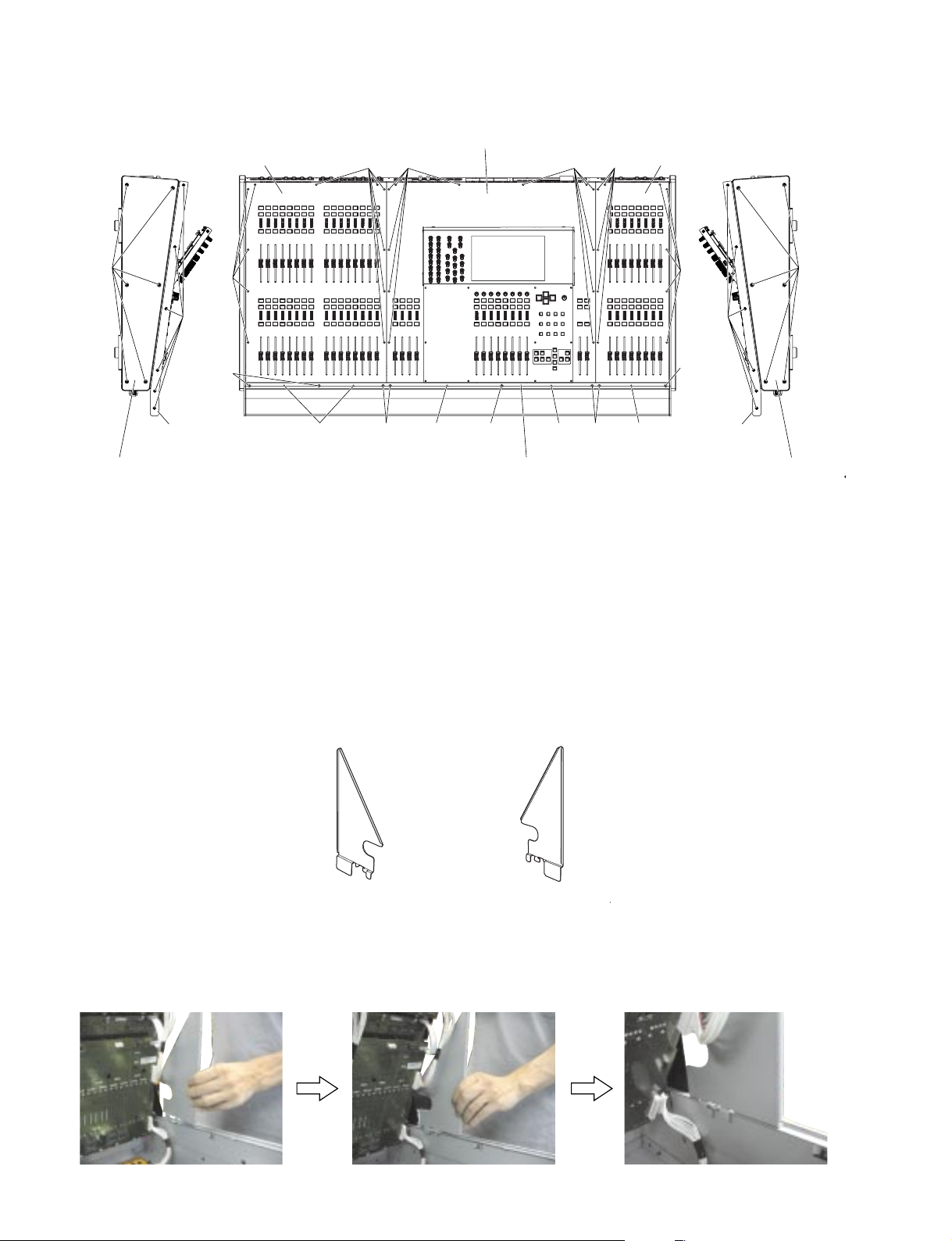
* Before proceeding to procedures 2 through 4,
prepare control panel stays L and R (tools for fixing
the control panels) in advance.
· Control panel stay L (WE758900)
· Control panel stay R (WE759000)
[12B] [12B] [32A][52B][52B] [52B]
Front plate 48
(フロントプレート48)
Fig.1-2 (図1-2)
※ 2項〜4項の作業を行う前に、コンパネステーL、R(コ
ントロールパネル固定用工具)を用意してくださ
い。(図2、写真2)
・コンパネステーL(WE758900)
・コンパネステーR(WE759000)
[32A]
[1320B]
[52B]
Side pad R
(サイドアルミパッドR)
Wood panel R
(ウッドパネルR)
[1370B]
Control panel stay L
(コンパネステーL)
Fig.2 (図2)
Control panel stay R
(コンパネステーR
● Installing the control panel stay L(コンパネステーLの取り付け方)
123
26
Photo 2 (写真2)
M7CL-32/M7CL-48
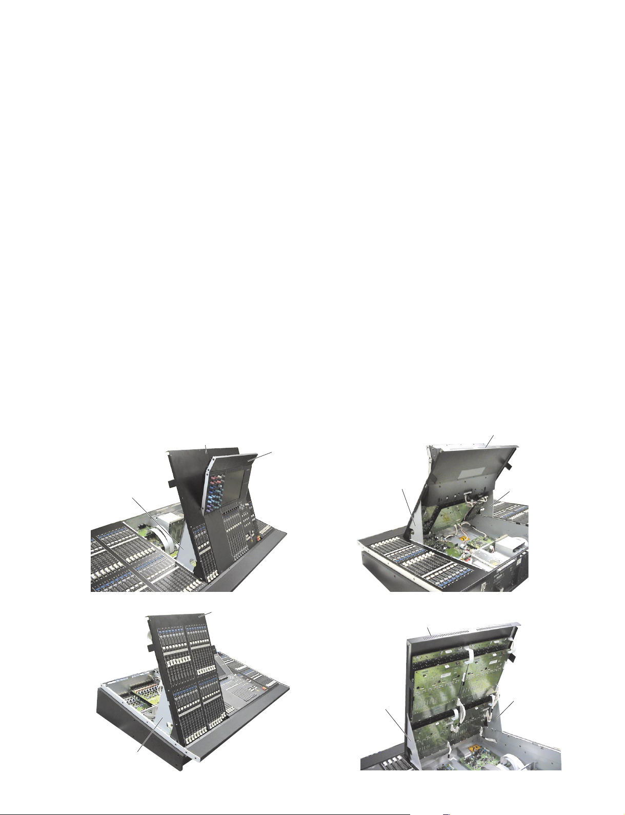
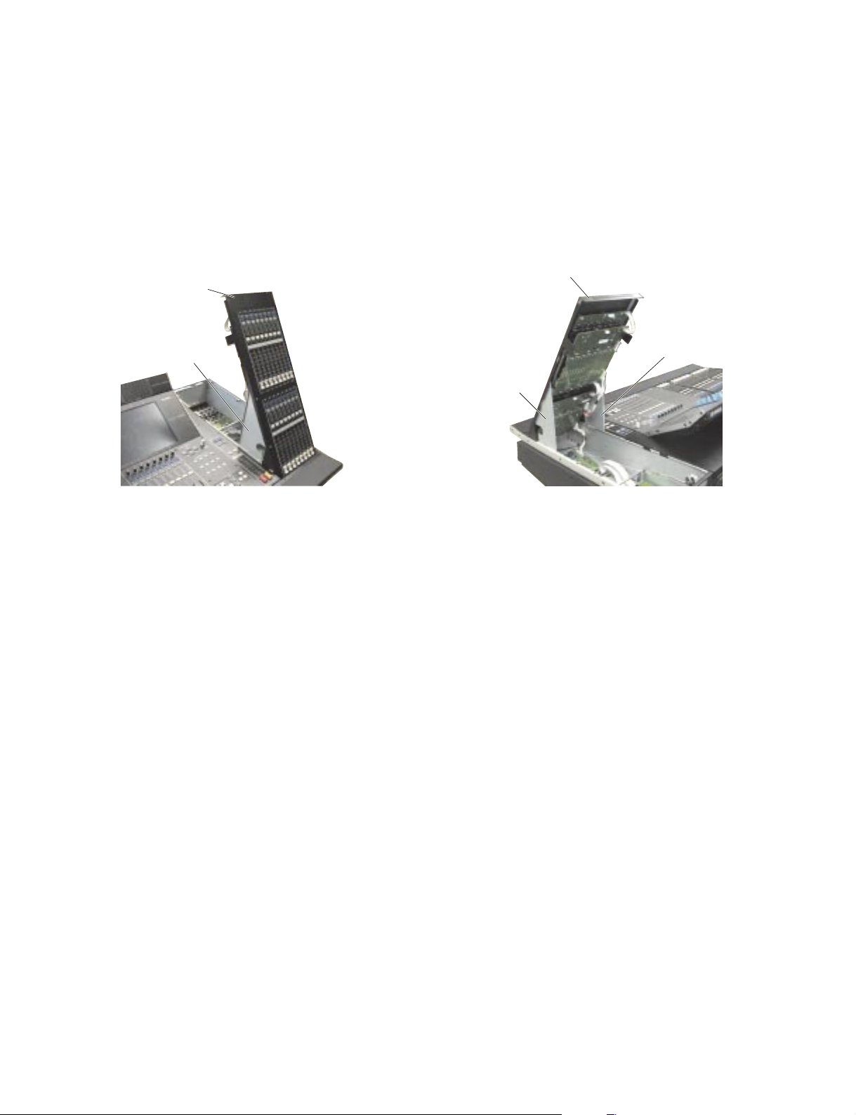
2. Control Panel 1 Assembly 32 (M7CL-32), Control Panel 1 Assembly 48 (M7CL-48)
(Time required: About 4 minutes)
2-1 Remove the front plate. (See procedure 1)
2-2 M7CL-32: Remove the fourteen (14) screws
marked [12A]. (Fig.1-1)
M7CL-48: Remove the fourteen (14) screws
marked [12B]. (Fig.1-2)
2-3 Lift the control panel 1 assembly 32 of the M7CL-
32 or the control panel 1 assembly 48 of the M7CL48 from the rear side and fix it with the control panel
stays L and R. (Photo 3)
* To remove the control panel 1 assembly,
disconnect the connector assembly first and
then lift the control panel 1 assembly.
3. Control Panel 2 Assembly
(Time required: About 4 minutes)
3-1 Remove the front plate. (See procedure 1)
3-2 M7CL-32: Remove the thirteen (13) screws marked
[22A]. (Fig.1-1)
M7CL-48: Remove the thirteen (13) screws marked
[22B]. (Fig.1-2)
3-3 Lift the control panel 2 assembly from the rear side and
fix it with the control panel stays L and R. (Photo 4)
* To remove the control panel 2 assembly,
disconnect the connector assembly first and
then lift the control panel 2 assembly.
● M7CL-48
Control panel 1 assembly
(コンパネ1 Ass'y)
MBM7CL (Option)
2. コンパネ1Ass'y32(M7CL-32)、コンパネ1
Ass'y48(M7CL-48)
2-1 フロントプレートを外します。(1項参照)
2-2 M7CL-32:[12A]のネジ14本を外します。(図1-1)
M7CL-48:[12B]のネジ14本を外します。(図1-2)
2-3 M7CL-32の場合は、コ ンパネ1Ass'y32を、M7CL-48
の場合は、コンパネ1Ass'y48をリア側から持ち上げ
て、コンパネステーL、Rで固定します。(写真3)
※ コンパネ1Ass'y本体を取り外す場合は、束線を外し
てから、持ち上げて外します。
(所要時間:約4分)
3. コンパネ2Ass'y(所要時間:約4分)
3-1 フロントプレートを外します。(1項参照)
3-2 M7CL-32:[22A]のネジ13本を外します。(図1-1)
M7CL-48:[22B]のネジ13本を外します。(図1-2)
3-3 コンパネ2Ass'yをリア側から持上げて、コンパネス
テーL、Rで固定します。(写真4)
※ コンパネ2Ass'y本体を取り外す場合は、束線を外し
てから、持ち上げて外します。
Control panel 1 assembly
(コンパネ1 Ass'y)
Control panel stay L
(コンパネステーL)
● M7CL-48
Control panel stay L
(コンパネステーL)
Photo 3 (写真3)
Control panel 2 assembly
(コンパネ2 Ass'y)
Photo 4 (写真4)
Control panel stay R
(コンパネステーR)
Control panel 2 assembly
(コンパネ2 Ass'y)
Control panel stay R
(コンパネステーR)
Control panel stay L
(コンパネステーL)
Control panel stay L
(コンパネステーL)
27
M7CL-32/M7CL-48
4. Control Panel 3 Assemb ly (M7CL-48 only)
(Time required: About 3 minutes)
4-1 Remove the front plate. (See procedure 1)
4-2 Remove the eleven (11) screws marked [32A].
(Fig.1-2)
4-3 Lift the control panel 3 assembly from the rear side and
fix it with the control panel stays L and R. (Photo 5)
* To remove the control panel 3 assembly,
disconnect the connector assembly first and
then lift the control panel 3 assembly.
● M7CL-48
Control panel 3 assembly
(コンパネ3 Ass'y)
Control panel stay L
(コンパネステーL)
Photo 5 (写真5)
4. コンパネ3Ass'y(M7CL-48のみ)
(所要時間:約3 分)
4-1 フロントプレートを外しま す。(1項参照)
4-2 [32A]のネジ11本を外します。(図1-2)
4-3 コンパネ3Ass'yをリア側から持上 げて、コンパネス
テーL、Rで固定します。(写真5)
※ コンパネ3Ass'y本体を 取り 外す場合 は、束線を外し
てから、持ち上げて外します。
Control panel 3 assembly
(コンパネ3 Ass'y)
Control panel stay L
(コンパネステーL)
Control panel stay R
(コンパネステーR)
5. Side Pad L, R
(Time required: About 1 minute each)
5-1 Side Pad L:
5-1-1 Remove the six (6) screws marked [1320A]. The
side pad L can then be removed. (Fig.1-1, Fig.1-2)
5-2 Side Pad R:
5-2-1 Remove the six (6) screws marked [1320B]. The
side pad R can then be removed. (Fig.1-1, Fig.1-2)
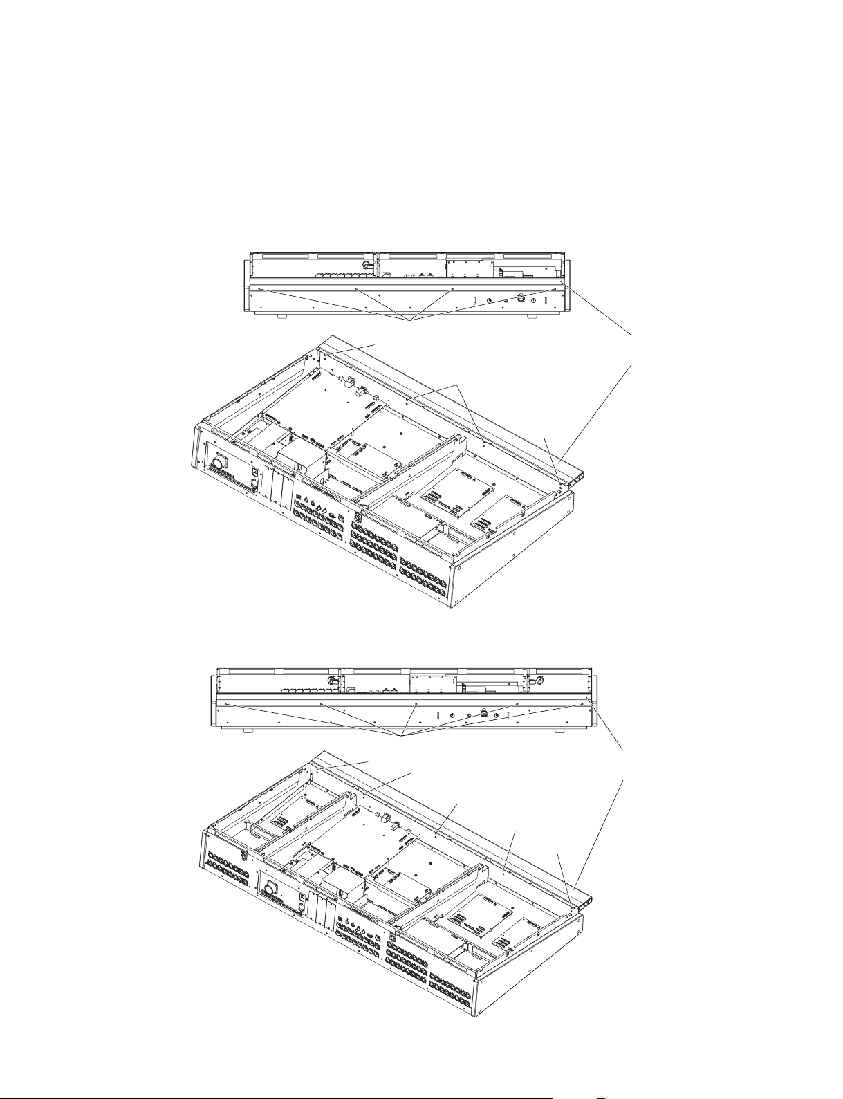
6. Front Pad Assembly 32 (M7CL-32)
(Time required: About 9 minutes),
Front Pad Assembly 48 (M7CL-48)
(Time required: About 11 minutes)
6-1 Remove the front plate. (See procedure 1)
6-2 Remove the control panel 1 assembly. (See
procedure 2)
6-3 Remove the control panel 2 assembly. (See
procedure 3)
6-4 Remove the control panel 3 assembly. (M7CL-48
only) (See procedure 4)
6-5 Remove the side pads L and R. (See procedure 5)
6-6 M7CL-32: Remove the six (6) screws marked
[960A] and loosen the two (2) screws
marked [960B]. Lift the front pad
assembly 32 a little and remove it. (Fig.3)
M7CL-48: Remove the eight (8) screws marked
[960C] and loosen the two (2) screws
marked [960D]. Lift the front pad
assembly 48 a little and remove it. (Fig.4)
5. サイドアルミパッドL、R(所要時間:各約1分)
5-1 サイドアルミパッドL:
5-1-1 [1320A]のネジ6本を外して、サイドアルミパッドL
を外します。(図1-1、図1-2)
5-2 サイドアルミパッドR:
5-2-1 [1320B]のネジ6本を外して、サイドアルミパッドR
を外します。(図1-1、図1-2)
6. FパッドAss'y32(M7CL-32)(所要時間:約9分)、
FパッドAss'y 48(M7CL-48)
6-1 フロントプレートを外します。(1項参照)
6-2 コンパネ1Ass'yを外します。(2項参照)
6-3 コンパネ2Ass'yを外します。(3項参照)
6-4 コンパネ3Ass'yを外します。(M7CL-48のみ)
(4項参照)
6-5 サイドアルミパッドL、Rを外します。(5項参照)
6-6 M7CL-32:[960A]のネジ6本を外し、[960B]のネジ
2本を緩めて、FパッドAss'y32を少し上
へ持ち上げて外します。(図3)
M7CL-48:[960C]のネジ8本を外し、[960D]のネジ
2本を緩めて、FパッドAss'y48を少し上
へ持ち上げて外します。(図4)
(所要時間:約11分)
28
M7CL-32/M7CL-48
7. Wood Panel L, R
(Time required: About 1 minute each)
7-1 Wood Panel L:
7-1-1 Remov e the six (6) screws marked [1370A]. The wood
panel L can then be removed. (Fig.1-1, Fig.1-2)
7-2 Wood Panel R:
7-2-1 Remov e the six (6) screws mark ed [1370B]. The wood
panel R can then be removed. (Fig.1-1, Fig.1-2)
● M7CL-32
<Front view>
[960A]
[960A]
7. ウッドパネルL、R(所要時間:各約1分)
7-1 ウッドパネルL:
7-1-1 [1370A]のネジ6本を外して、ウッドパネルLを外し
ます。(図1-1、図1-2)
7-2 ウッドパネルR:
7-2-1 [1370B]のネジ6本を外して、ウッドパネルRを外し
ます。(図1-1、図1-2)
Front pad assembly 32
(FパッドAss'y 32)
[960B]
[960A]
● M7CL-48
[960]: Bind Head Tapping Screw-B (Bタイト+BIND) 4.0X8 MFZN2B3 (WE962000)
Fig.3 (図3)
<Front view>
[960C]
[960C]
[960D]
[960C]
[960D]
Front pad assembly 48
(FパッドAss'y 48)
[960C]
[960]: Bind Head Tapping Screw-B (Bタイト+BIND) 4.0X8 MFZN2B3 (WE962000)
Fig.4 (図4)
29
M7CL-32/M7CL-48
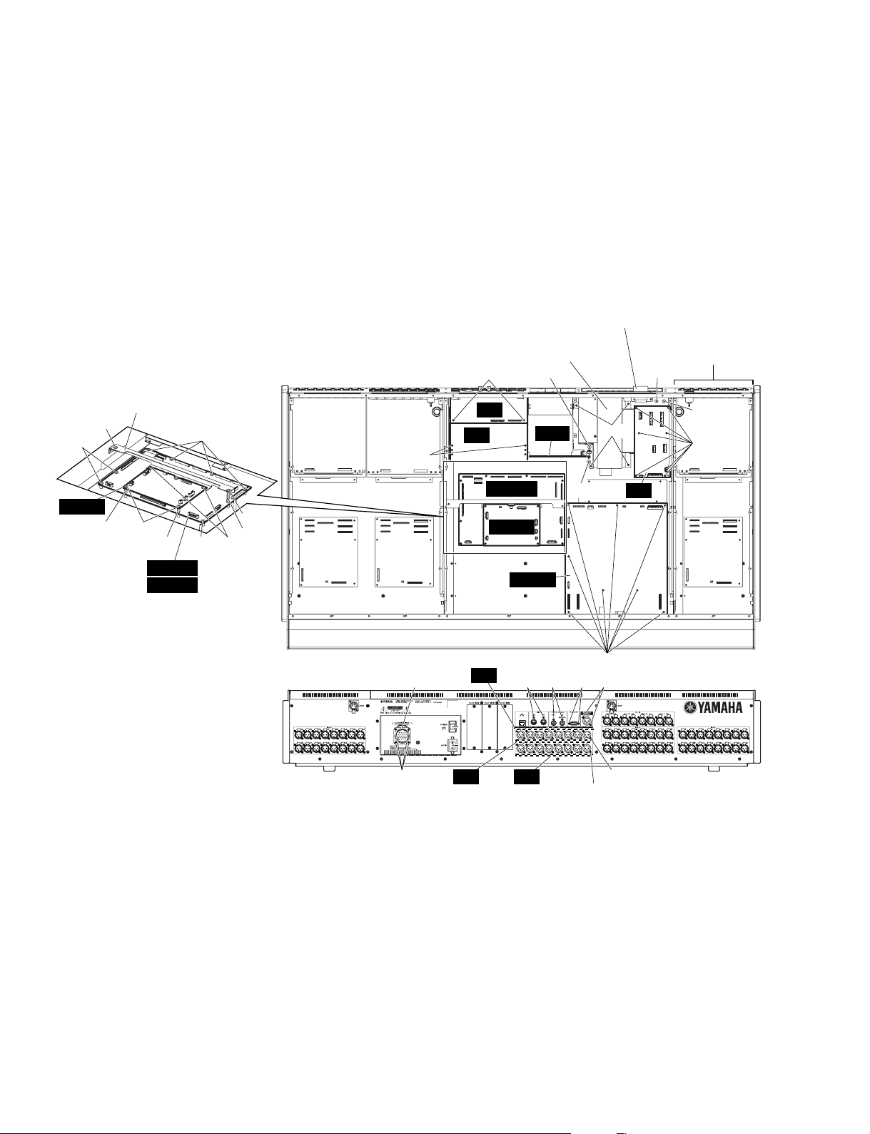
A.
Disassembly Procedure of Bottom Assemb ly section underneath Control P anel 1 Assembly
(コンパネ 1Ass'y 下のボトム Ass'y 部の分解)
A-1. CPUM Circuit Board Assembly
(Time required: About 4 minutes)
A-1-1 Remove the front plate. (See procedure 1)
A-1-2 Fix the control panel 1 assembly. (See procedure 2)
A-1-3 Remove the two (2) screws marked [1080A], and
two (2) screws marked [1080B]. The CPUM circuit
board assembly can then be removed. (Fig.5)
* MAC (Media Access Control) address is stored
in the CPUM circuit board assembly. If the CPUM
circuit board assembly is replaced, MAC
address will be changed.
● M7CL-48
<Top view>
CPU holder
(CPUアングル)
[1060]
[1010]
CPUM
[1020]
[1080A]
[1020] [1010]
DSP32
DSP48
[1010]
[1050]
[1030]
[1080B]
(M7CL-32)
(M7CL-48)
[550A]
A-1. CPUMシートAss'y(所要時間:約4分)
A-1-1 フロントプレートを外します。(1項参照)
A-1-2 コンパネ1Ass'yを固定します。(2項参照)
A-1-3 [1080A]のネジ2本と[1080B]のネジ2本を外して、
CPUMシートAss'yを外します。(図5)
※ CPUMシートAss'yには、MAC(MediaAccess
Control)アドレスが設定されています。CPUMシート
Ass'yを交換すると、MACアドレスが変更されます。
Receptacle assembly
(レセプタクルAss'y)
Power supply assembly
(電源Ass'y)
[640]
[330]
JK
DA
(1/2)
OPT
DSP48
[320]
[485]
The M7CL-32 does
∗
not have this section.
M7CL-32には、この
※
部分がありません。
[270A]
DC
[220A]
[210A]
CPUM
DCMS
30
<Rear view>
This figure shows the M7CL-48.∗
この図は、M7CL-48です。※
[210A]: Bind Head Tapping Screw-S (Sタイト+BIND) 3.0X6 MFZN2W3 (WE877900)
[220A]: Bind Head Tapping Screw-S (Sタイト+BIND) 4.0X6 MFZN2W3 (WF215300)
[260A]: Bonding T apping Screw-B (Bタイト+BOND) 3.0X8 MFZN2B3 (WE774100)
[270A]: Bind Head Tapping Screw-S (Sタイト+BIND) 4.0X6 MFZN2W3 (WF215300)
[320]: Bind Head Tapping Screw-S (Sタイト+BIND) 3.0X6 MFZN2W3 (WE877900)
[330]: Bind Head Tapping Screw-S (Sタイト+BIND) 4.0X6 MFZN2W3 (WF215300)
[485]: Bind Head Tapping Screw-S (Sタイト+BIND) 4.0X6 MFZN2W3 (WF215300)
[540]: Bonding Tapping Screw-B (Bタイト+BOND) 3.0X8 MFZN2B3 (WE774100)
[550A]: Bind Head Tapping Screw-S (Sタイト+BIND) 3.0X6 MFZN2W3 (WE877900)
[610]: Bonding Tapping Screw-B (Bタイト+BOND) 3.0X8 MFZN2B3 (WE774100)
[620]: Bind Head Screw (小ネジ+BIND) 3.0X6 MFZN2B3 (WE878300)
[630]: Lock Screw (ロックネジ) 17L-003C41 (V3768900)
[640]: Bind Head Tapping Screw-S (Sタイト+BIND) 3.0X6 MFZN2W3 (WE877900)
[1010]: Bind Head Tapping Screw-S (Sタイト+BIND) 3.0X6 MFZN2W3 (WE877900)
[1020]: Spacer (六角スペーサ) M3 L=13mm (WE955300)
[1030]: Spacer (六角スペーサ) BSB-330 (WC390400)
[1050]: Bind Head Tapping Screw-S (Sタイト+BIND) 3.0X6 MFZN2W3 (WE877900)
[1060]: Bind Head Tapping Screw-S (Sタイト+BIND) 4.0X6 MFZN2W3 (WF215300)
[1080]: Bind Head Tapping Screw-S (Sタイト+BIND) 3.0X6 MFZN2W3 (WE877900)
[1180]: Bind Head Tapping Screw-S (Sタイト+BIND) 3.0X6 MFZN2W3 (WE877900)
Receptacle assembly
(レセプタクルAss'y)
[260A] [540A] x 16
Fig.5 (図5)
DA
JK
(1/2)
[610]
DA
(2/2)
[1180]
[610][620] [630]
[540B] x 16
 Loading...