

JT1-JT2
SERIES
ASSEMBLY
MANUAL
LIT
11662-88-72
Introduction
The
individu I who
pr
p r s Y m h
motorcycl
for d liv ry ha
th
responsibility
of
b irn . n
import
nt
link b tw,
,n
th
factory
nd
th
custom
r.
Th
tI f
t1on
that
th
cu tornr:ir
will
r c
iv
from
hi
Yamaha. both
1n1ti
II
nd ov r
th
l1f
of
th"
rn
chin
, is v ry
much
dep
nd
nt
on
th
c r
with
which
th
s t-up
proc
~ctur
i p rforrn d.
As
the
on
doing
the
work
. you hould b
owur
of
this r
sponsibility
.
Th
degr
of
car
that
you
t,1k
in
doing
th \ job
will
rcfl
ct
on you .
the
deal
r.
and
th
factory
A properly s t up
Yamaha
will
give
many
miles
of
satisfaction
to
th
owner
and
1s
important
to
future
sales and
service
business On the
other
hand. a
poorly
prepared
machine
is sure
to
result
in
a dissat1sf1ed
customer
and possibly extra
work
due
to
the
need
for
subsequent
re
doing
of
portions
of
the
Job
Follow
the
procedures
in
this
manual
rn
the
order
in
which
they
are
presented
Don
't
skip around and
perform
them
out
of
sequence, and
don't
omit
any
of
them
. They are all essential
to a well
done
Job
Remember, this
initial
set
up
Is
the
most
important
servicing
the
motorcycle
will
ever
receive .
Service Department
Yamaha International Corporation
Buena
Park,
California 90620
JT
1/ JT2
SERI
ES
ASSEMBLY
MANUAL
1st
Printing
July,
1972
Copyright
©
1972
Yamaha
International
Corp.
All
Rights
Reserved
Yam oho
Int'
I.
Corp.,
Buena
Pork,
Calif.
JTt/JT2
SRS
ASSY
MNL
P N
LIT
11662-88-72
Table
of
Contents
Section
I -
Unpacking
The
Motorcycle
Page
A.
Opening
the
Carton
................................
.
B.
Checking
for
Damage
and
Shortages
.................
.
Section
II -
Assembling
The
Motorcycle
1
2
A.
Installing
the
Handlebars
. . . . . . . . . . . . . . . . . . . . . . . . . . . . 3
B.
Installing
the
Front
Fender . . . . . . . . . . . . . . . . . . . . . . . . . . 4
C.
Installing
the
Front
Wheel
. . . . . . . . . . . . . . . . . . . . . . . . . . . 5
D.
Installing
the
Footrests
. . . . . . . . . . . . . . . . . . . . . . . . . . . . . . 7
E.
Installing
the
Transmission
Change Pedal . . . . . . . . . . . . . . 7
F.
Attaching
the
Brake Cable
to
the
Front Brake . . . . . . . . . . 8
G.
Securing
Clutch
and
Brake
Cables
to
the
Levers . . . . . . . . 8
H.
Installing
the
Rear Brake Rod . . . . . . . . . . . . . . . . . . . . . . . . . 9
I.
Installing
the
Tail
Light
. . . . . . . . . . . . . . . . . . . . . . . . . . . . . . .
10
J .
Connecting
Wiring
. . . . . . . . . . . . . . . . . . . . . . . . . . . . . . . . . . . 11
K.
Connecting
the
Throttle
Control
. . . . . . . . . . . . . . . . . . . . . . .
12
Section
111 -Adjusting
Components
A.
Adjusting
the
Front Brake . . . . . . . . . . . . . . . . . . . . . . . . . . . .
13
B.
Adjusting
the
Clutch
. . . . . . . . . . . . . . . . . . . . . . . . . . . . . . . . .
14
C.
Adjusting
the
Chain . . . . . . . . . . . . . . . . . . . . . . . . . . . . . . . . . .
15
D.
Adjusting
the
Rear Brake . . . . . . . . . . . . . . . . . . . . . . . . . . . . .
16
E.
Bleeding
the
Autolube
Pump
......
...
....
.........
....
16
F.
Checking
Autolube
Pump
Minimum
Stroke . . . . . . . . . . . . . .
18
G.
Adjusting
the
Carburetor
. . . . . . . . . . . . . . . . . . . . . . . . . . . . .
18
H.
Checking
Ignition
Timing
......
..........
............
.
19
Section
IV -Making
Preliminary
Checks
A. Filling Fuel
Tank
............
......................
22
B.
Checking
Transmission
Oil Level
....
.......
....
....
.. ..
23
C.
Checking
for
Loose
Nuts
and
Bolts .............
.
.......
23
D.
Checking
Tire
Pressure
...
. .
...
...
....
.........
. .
...
• .
24
Section
V -
Making
Running Checks
A.
Starting
the
Engine
.. ..
....
• • • • • • • • · · · · · · · · · · · · · · · · · ·
25
B.
Checking
the
Transmission
Oil . . . . . . . . . . . . . . . . . . . . . . . .
25
c.
Adjusting
Carburetor
and
Autolube
Cable
....
......
....
26
D.
Checking
Lights
.......
......
· . · · · · · · · · · · · · · · · · · · · · · ·
27
E. Road
Testing
.............
. . • • • • • • • • • • • • • • • • • · • • • · • · ·
28
Section
VI
-
JT2
Supplement
A.
Miscellaneous
Section
VII
- Service Data
Page
. . . . .
31
A.
Torque Specif i co ti ons . . . . . . . . . . . . . . . . . . . . . . . . .
36
Section I - Unpacking
the
Motorcycle
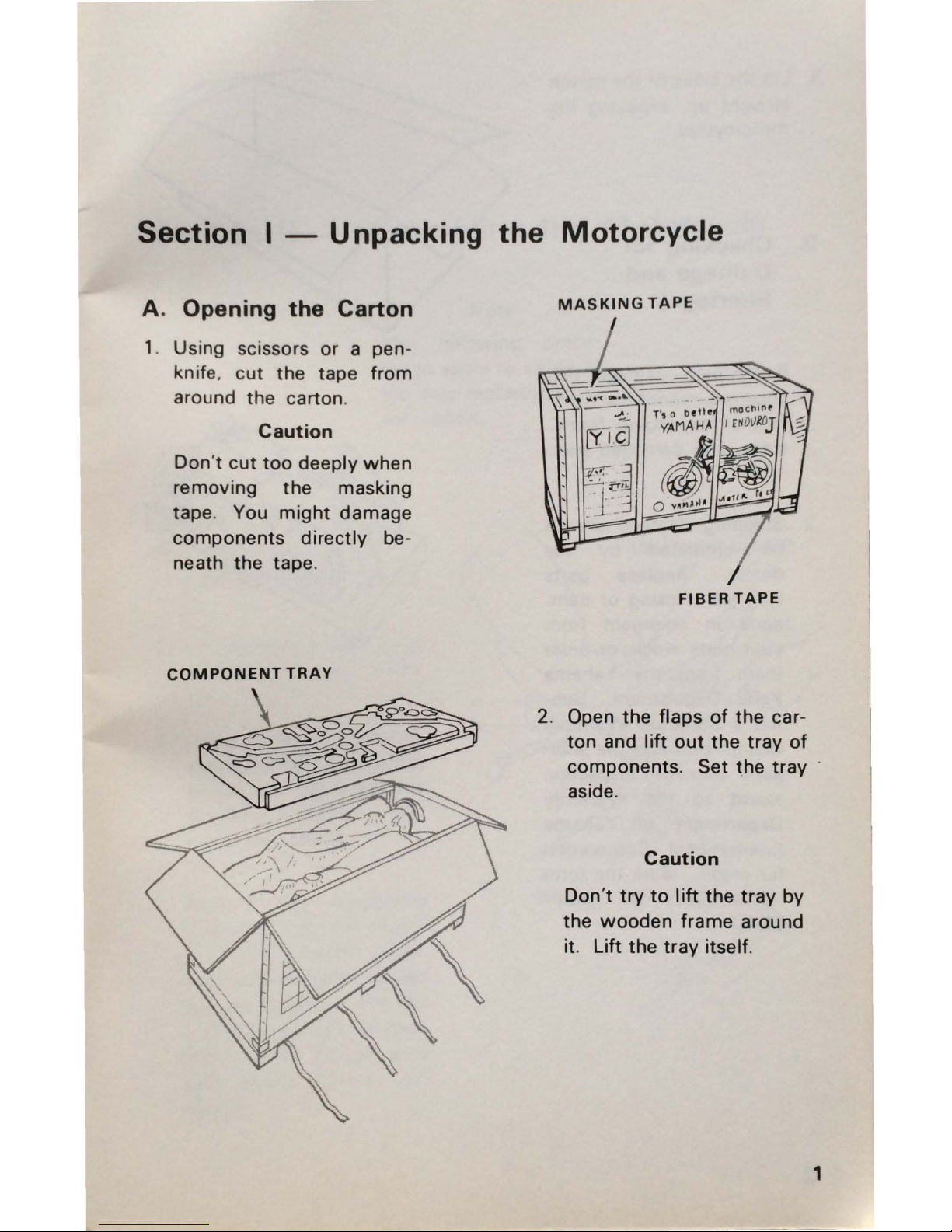
A. Opening
the
Carton
1. Using scissors
or
a pen-
knife .
cut
the
tape
from
around
the
carton.
Caution
Don't
cut
too
deeply
when
removing
the
masking
tape. You
might
damage
components
directly
be-
neath
the
tape
.
COMPONENT
TRAY
MASKING
TAPE
FIBER
TAPE
2. Open
the
flaps
of
the
car-
ton
and I
ift
out
the
tray
of
components. Set
the
tray
·
aside.
Caution
Don't
try
to
lift
the
tray
by
the
wooden
frame
around
it. Lift
the
tray
itself.
1
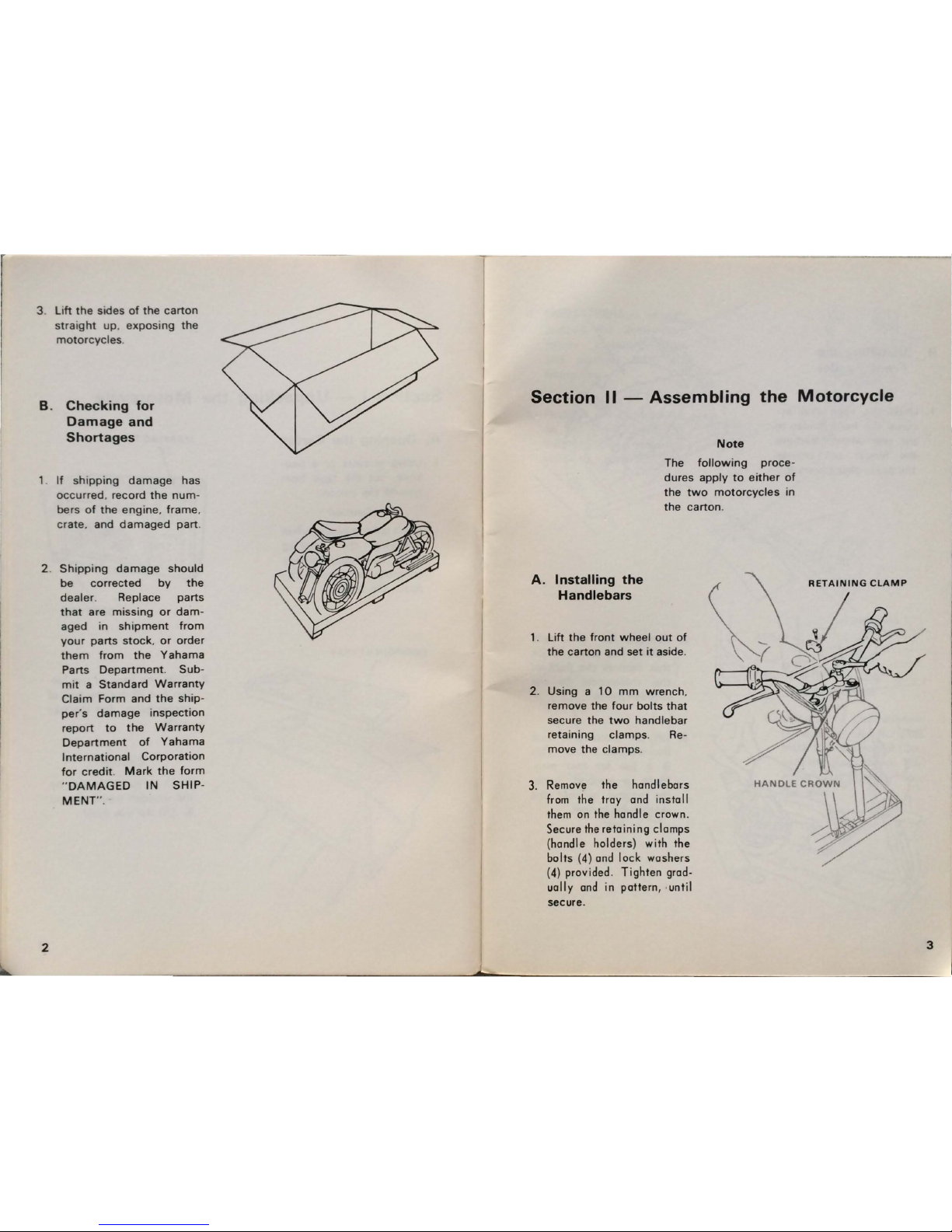
3.
Lift
the
sides
of
the
carton
straight up.
exposing
the
motorcycles
B.
Checking
for
Damage
and
Shortages
1.
If
shipping
damage
has
occurred
, record
the
num-
bers
of
the
engine. frame
,
crate
, and
damaged
part
.
2.
Shipping
damage
should
be
corrected
by
the
dealer
. Replace
parts
that
are
missing
or
dam-
aged
in
shipment
from
your
parts
stock,
or
order
them
from
the
Yahama
Parts
Department. Sub-
mit a Standard
Warranty
Claim
Form
and
the
ship-
per
's
damage
inspection
report
to
the
Warranty
Department
of
Yahama
International
Corporation
for
credit
. Mark
the
form
"DAMAGED
IN
SHIP-
MENT"
.
2
Section
11
- Assembling
the
Motorcycle
Note
The
following
proce-
dures
apply
to
either
of
the
two
motorcycles
in
the
carton
.
A.
Installing
the
Handlebars
1. L
ift
the
front
wheel
out
of
the
carton
and
set
it
aside.
2. Using a
10
mm
wrench
.
remove
the
four
bolts
that
secure the
two
handlebar
retaining
clamps
. Re-
move the
clamps
.
3.
Remove
the
handlebars
from the
tray
and
ins
ta II
them on the handle crown.
Secure the
retaining
clamps
(handle holders)
with
the
bolts
(4)
and
lock
washers
(4)
provided.
Tighten
grad-
ually
and
in
pattern, ,
until
secure.
RETAINING
CLAMP
3
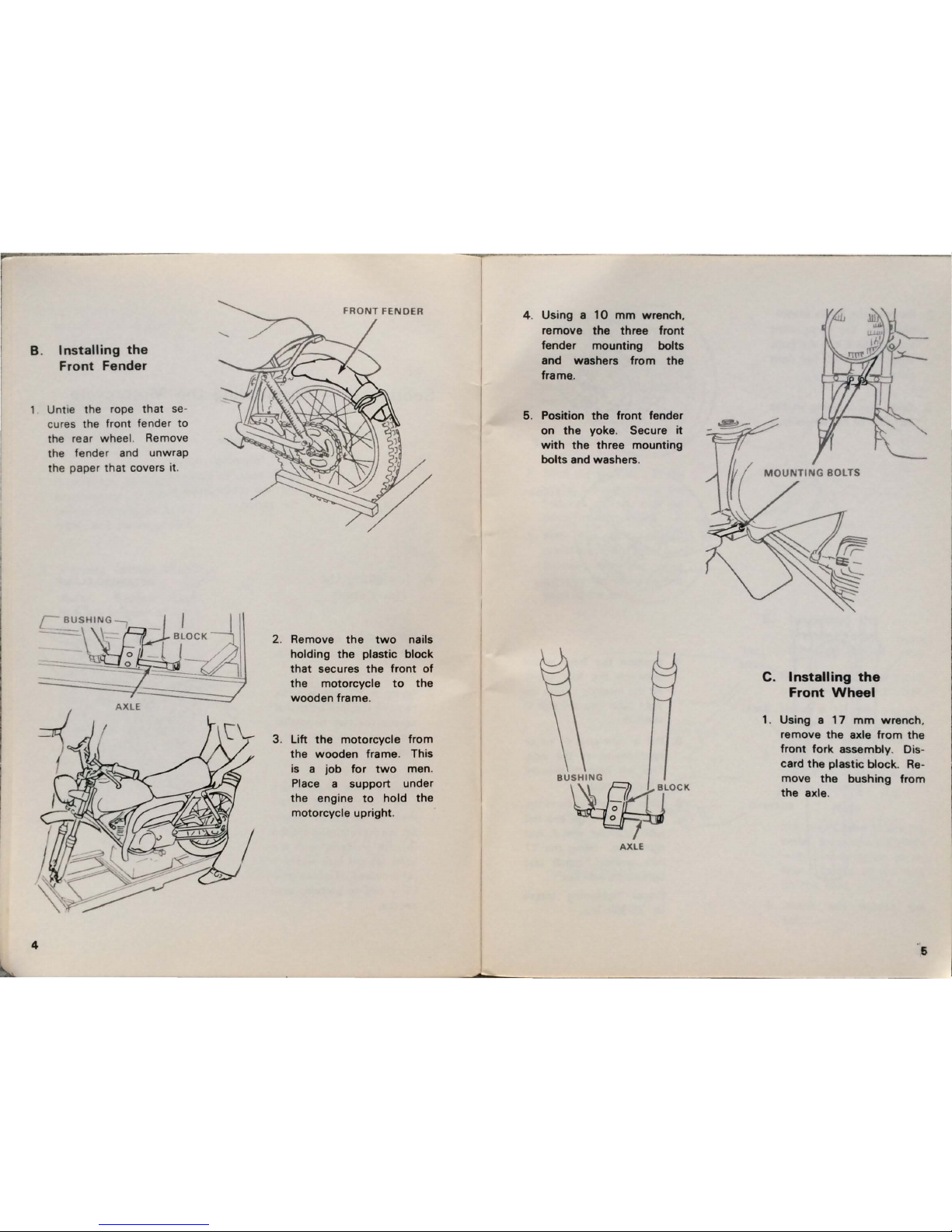
8 .
Installing
the
Front
Fender
4
Untie the rope
that se-
cures the front fender
to
the rear wheel. Remove
the fender and unwrap
the paper
that
covers it.
FRO
NT FENDER
2. Remove
the
two
nails
holding the plastic
block
that
secures
the
front
of
the
motorcycle
to
the
wooden
frame
.
3. Lift
the
motorcycle from
the
wooden
frame
. This
is a
job
for
two
men.
Place a
support
under
the
engine
to
hold
the
motorcycle
upright
.
4. Using a
10
mm
wrench
.
remove
the
three
front
fender
mounting
bolts
and washers
from
the
frame..
5. Position
the
front
fender
on
the
yoke. Secure
it
with
the
three
mounting
bolts and washers.
BUSHING
~ LOCK
AXLE
C. Installing
the
Front
Wheel
1. Using a
17
mm
wrench
.
remove
the
axle
from
the
front
fork
assembly. Dis-
card
the
plastic
block. Re
-
move
the
bushing
from
the
axle.
6

2. Remove
the
brake
assem-
'
bly
from
the
component
tray. Slide
it
into
the
front
wheel
hub
from
the
right
side
.
3.
Slide
the
bushing
in
the
left
side
of
the
wheel
hub
.
RIGHT
TUBE
6
BUSHING
BUSHING
LEFT
SIDE
4. Position
the
front
wheel
between
the
fork
tubes
.
Fit
the
locating
lug
on
the
right
tube
into
the
slot
in
the
hub.
5. Put a
light
coat
of
oil
or
light
grease
on
the
axle.
This
will
help
to
prevent
it
from
rusting.
6. Slide
the
axle in
from
the
left
side
through
the
left
tube. bushing,
wheel
, and
right
tube. Using
the
17
mm
wrench,
install
and
tighten
the
axle
nut
.
Proper
tightening
torque
is
: 25-30ft/ lbs.
D.
Installing
the
Footrests
1. Remove
the
footrest. pin
and
cotter
pin
from
the
plastic
bag
in
the
compo
-
nent
tray
.
Note
The
following
steps
apply
to
either
footrest
.
2. Slide
the
footrest
into
the
frame
bracket
. Hold
the
footrest
vertical.
with
the
cover
tread
forward
.
3. Slide
the
pin
(head
for
-
ward)
into
the
bracket and
footrest
. Slide
the
cotter
pin
into
the
pin
hole
and
bend
up
the
ends.
CHANGE
PEDAL
E.
Installing
the
Transmission
Change
Pedal
1.
Remove
the
change
pedal
from
the
component
tray
.
2.
Using
a
10
mm
wrench
.
remove
the
bolt
from
the
pedal
and
set
it aside.
3. Push
the
pedal
on
the
splined
stud
with
the
arm
facing
forward
.
Note
You
might
have
to
pry
the
pedal
jaws
apart
slightly
with a screwdriver
to
al-
low
it
to
slip
all
the
way
on
the
stud
.
4.
Install
and
tighten
the
bolt
.
7
 Loading...