


K-903
K-903
U C A
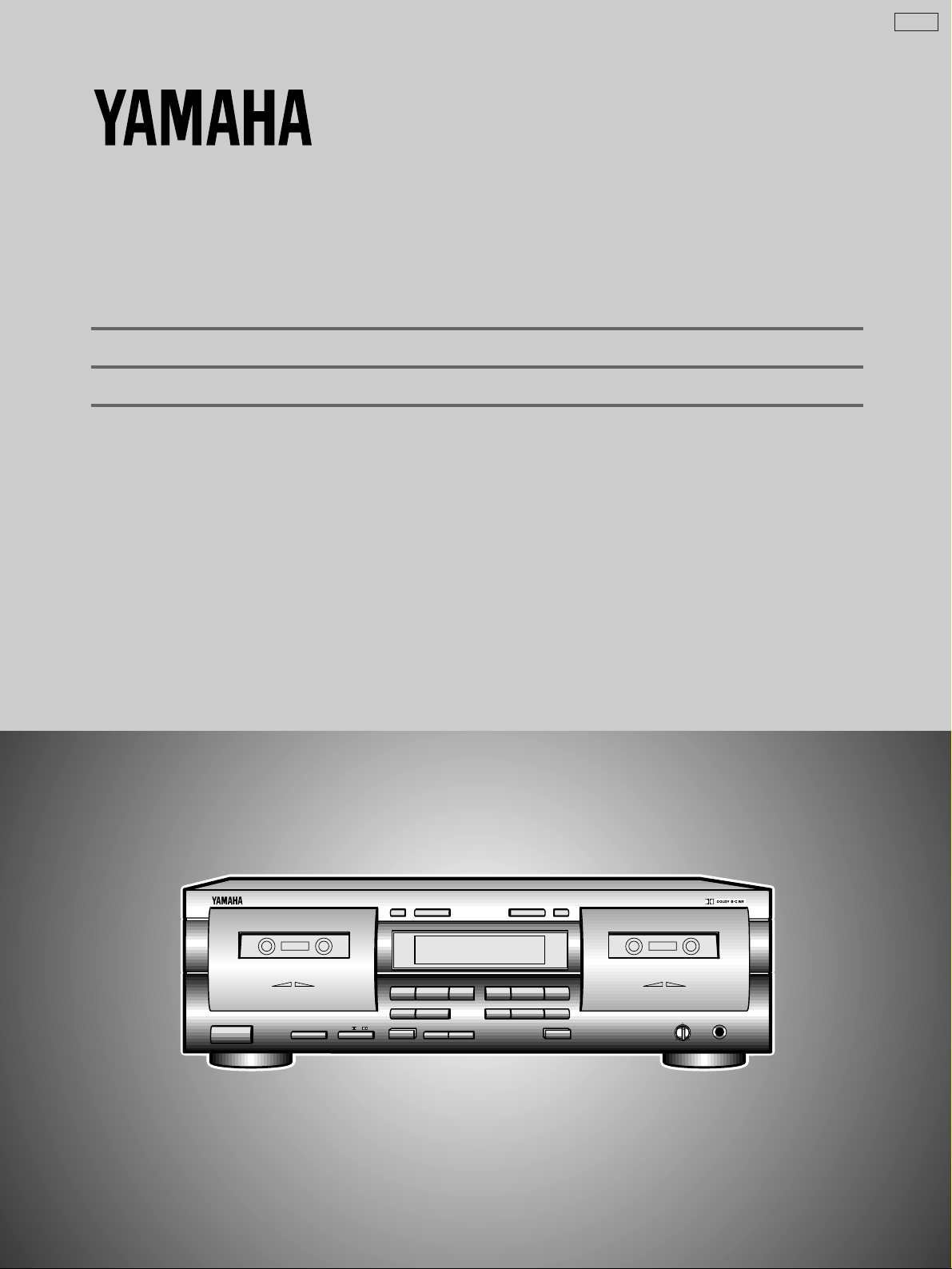
Natural Sound Stereo Cassette Deck
Platine à cassette stéréo de la série “Natural Sound”
OWNER’S MANUAL
MODE D’EMPLOI
NATURAL SOUND CASSETTE DECK K-903
PLAYBACK
STANDBY/ON
MODE
O / p / ∏ / RELAY
CLOSE % % CLOSE
! ⁄
DECK A
DOLBY NR
OFF/ B/ C
&
SEARCH
EJECT EJECT
DUBBING A # B
NORMAL HIGH
DIRECTION RESETRESET DIRECTION
!⁄
PLAYPLAY
&
MUTE/SEARCH
REC/PAUSE
RECORD/PLAYBACK
REC LEVEL
MIN MAX
DECK B
PHONES
Thank you for purchasing this YAMAHA stereo cassette deck.
SAFETY INSTRUCTIONS
CAUTION
RISK OF ELECTRIC SHOCK
DO NOT OPEN
CAUTION: TO REDUCE THE RISK OF ELECTRIC
SHOCK, DO NOT REMOVE COVER (OR BACK).
NO USER-SERVICEABLE PARTS INSIDE. REFER
SERVICING TO QUALIFIED SERVICE PERSONNEL.
÷ Explanation of Graphical Symbols
The lightning flash with arrowhead symbol,
within an equilateral triangle, is intended to
alert you to the presence of uninsulated
“dangerous voltage” within the product's
enclosure that may be of sufficient magnitude
to constitute a risk of electric shock to persons.
The exclamation point within an equilateral
triangle is intended to alert you to the presence
of important operating and maintenance
(servicing) instructions in the literature
accompanying the appliance.
WARNING
TO REDUCE THE RISK OF FIRE OR ELECTRIC
SHOCK, DO NOT EXPOSE THIS APPLIANCE TO RAIN
OR MOISTURE.
1 Read Instructions — All the safety and operating
instructions should be read before the unit is operated.
2 Retain Instructions — The safety and operating
instructions should be retained for future reference.
3 Heed Warnings — All warnings on the unit and in the
operating instructions should be adhered to.
4 Follow Instructions — All operating and other instructions
should be followed.
5 Water and Moisture — The unit should not be used near
water — for example, near a bathtub, washbowl, kitchen
sink, laundry tub, in a wet basement, or near swimming
pool, etc.
6 Carts and Stands — The unit should be used only with a
cart or stand that is recommended by the manufacturer.
6A A unit and cart combination
should be moved with care. Quick
stops, excessive force, and uneven
surfaces may cause the unit and cart
combination to overturn.
7 Wall or Ceiling Mounting — The unit should be mounted
to a wall or ceiling only as recommended by the
manufacturer.
8 Ventilation — The unit should be situated so that its
location or position does not interfere with its proper
ventilation. For example, the unit should not be situated on a
bed, sofa, rug or similar surfaces that may block the
ventilation openings: or placed in a built-in installation, such
as a bookcase or cabinet that may impede the flow of air
through the ventilation openings.
9 Heat — The unit should be situated away from heat
sources such as radiators, stoves, or other units that
produce heat.
10 Power Sources — The unit should be connected to a
power supply only of the type described in the operating
instructions or as marked on the unit.
11 Power-Cord Protection — Power-supply cords should
be routed so that they are not likely to be walked on or
pinched by items placed upon or against them, paying
attention to receptacles, and the point where they exit from
the unit.
12 Cleaning — The unit should be cleaned only as
recommended by the manufacturer.
13 No Use Periods — The power cord of the unit should be
unplugged from the outlet when left unused for a long
period of time.
14 Object and Liquid Entry — Care should be taken so
that objects do not fall into and liquids not spilled into the
inside of the unit.
15 Damage Requiring Service — The unit should be
serviced by qualified service personnel when:
A. The power-supply cord or the plug has been damaged;
or
B. Objects have fallen, or liquid has been spilled into the
unit; or
C. The unit has been exposed to rain; or
D. The unit does not appear to operate normally or exhibits
a marked change in performance; or
E. The unit has been dropped, or the cabinet damaged.
16 Servicing — The user should not attempt to service the
unit beyond those means described in the operating
instructions. All other servicing should be referred to
qualified service personnel.
17 Grounding or Polarization — The precautions should be
taken so that the grounding or polarization of the unit is not
defeated.
This unit is not disconnected from the AC power source
as long as it is connected to the wall outlet, even if the
unit itself is turned off. This state is called the standby
mode. In this state, the unit is designed to consume a
very small quantity of power.
2
CAUTION: READ THIS BEFORE OPERATING
YOUR UNIT.
FCC INFORMATION (U.S.A.)
1.IMPORTANT NOTICE: DO NOT MODIFY THIS UNIT!
This product, when installed as indicated in the
instructions contained in this manual, meets FCC
requirements. Modifications not expressly approved by
Yamaha may void your authority, granted by the FCC, to
use the product.
2.IMPORTANT: When connecting this product to
accessories and/or another product use only high quality
shielded cables. Cables supplied with this product
MUST be used. Follow all installation instructions.
Failure to follow instructions could void your FCC
authorization to use this product in the USA.
3.NOTE: This product has been tested and found to
comply with the requirements listed in FCC Regulations,
Part 15 for Class "B" digital devices. Compliance with
these requirements provides a reasonable level of
assurance that your use of this product in a residential
environment will not result in harmful interference with
other electronic devices. This equipment generates/uses
radio frequencies and, if not installed and used
according to the instructions found in the users manual,
may cause interference harmful to the operation of other
electronic devices. Compliance with FCC regulations
does not guarantee that interference will not occur in all
installations. If this product is found to be the source of
interference, which can be determined by turning the unit
"OFF" and "ON", please try to eliminate the problem by
using one of the following measures:
Relocate either this product or the device that is being
affected by the interference.
Utilize power outlets that are on different branch (circuit
breaker or fuse) circuits or install AC line filter/s.
In the case of radio or TV interference, relocate/reorient
the antenna. If the antenna lead-in is 300 ohm ribbon
lead, change the lead-in to coaxial type cable.
If these corrective measures do not produce satisfactory
results, please contact your local retailer that is
authorized to distribute this type of product. If you
cannot locate the appropriate retailer, please contact
Yamaha Electronics Corp., U.S.A.
6660 Orangethorpe Ave, Buena Park, CA 90620
The above statements apply ONLY to those products
distributed by Yamaha Corporation of America or its
subsidiaries.
1. This unit is a sophisticated stereo cassette deck. To ensure
proper operation for the best possible performance, please
read this manual carefully.
2. Choose the installation location of your unit carefully. Avoid
placing it in direct sunlight or close to source of heat. Also
avoid locations subject to vibration and excessive dust, heat,
cold or moisture. Keep it away from sources of hum such as
transformers or motors.
3. Do not open the cabinet as this may result in damage to the
deck or electrical shock. If a foreign object should get into
the deck, contact your local dealer.
4. When removing the power plug from the wall outlet, always
pull directly on the plug; never pull the cord itself.
5. Do not apply excessive force when operating switches and
knobs.
6. When moving the deck, be sure to first pull out the power
plug and remove all cords connecting the deck to other
equipment.
7. Do not attempt to clean this unit with chemical solvents as
this may damage the finish. Use a clean, dry cloth.
8. Never allow metallic items (e.g. screwdrivers, tools, etc.) to
come near the record/playback head assembly. Doing so
may not only scratch or damage the head’s mirror-smooth
finish, it may also change the magnetic characteristics of the
heads, causing a deterioration in reproduction quality.
9. Although the record/playback head used in this unit is a high
quality head with outstanding reproduction characteristics, it
can become dirty through the use of old tapes or from dust
accumulation over time. This can have a serious effect on
reproduction quality. Clean the heads regularly with one of
the commonly available head cleaners or with cleaning
solutions as explained later in this manual.
10. Be sure to read the “TROUBLESHOOTING” section of this
manual for advice on common operating errors before
concluding that your unit is faulty.
11. Keep this manual in a safe place for future reference.
12. Voltage Selector (General model only)
The voltage selector on the rear panel of this unit must
be set for your local mains voltage BEFORE plugging in
the AC mains supply. (Voltage selector adjustable
between 110/120/220/240 V AC.)
Note
Please check the copyright laws in your country to record from
records, compact discs, radio, etc. Recording of copyright
material may infringe copyright laws.
ENGLISHFRANÇAISDEUTSCHSVENSKAITALIANOESPAÑOLDUTCH
We Want You Listening For A Lifetime
YAMAHA and the Electronic Industries Association's
Consumer Electronics Group want you to get the most out of
your equipment by playing it at a safe level. One that lets the
sound come through loud and clear without annoying blaring
or distortion – and, most importantly, without affecting your
sensitive hearing.
Since hearing damage from loud sounds
is often undetectable until it is too late,
YAMAHA and the Electronic Industries
Association's Consumer Electronics
Group recommend you avoid prolonged
exposure to excessive volume levels.
We
Want You
LISTENING
For A Lifetime
FOR CANADIAN CUSTOMERS
TO PREVENT ELECTRIC SHOCK, MATCH WIDE
BLADE OF PLUG TO WIDE SLOT AND FULLY
INSERT.
THIS CLASS B DIGITAL APPARATUS MEETS ALL
REQUIREMENTS OF THE CANADIAN
INTERFERENCE-CAUSING EQUIPMENT
REGULATIONS.
3
TABLE OF CONTENTS
FEATURES ......................................................................... 4
CONNECTIONS.................................................................. 5
NOTES ON THIS MANUAL ................................................ 5
PLAYBACK (Common to DECKs A and B)......................... 6
BASIC OPERATION........................................................ 6
SELECTION SEARCH .................................................... 8
RELAY PLAYBACK ......................................................... 9
RECORDING .................................................................... 10
BASIC OPERATION...................................................... 10
REC MUTE OPERATION.............................................. 12
REC RETURN OPERATION ......................................... 12
FEATURES
÷ High Quality Hard Permalloy Recording/Playback Head in
Deck B and Playback Head in Deck A
÷ Dolby B/C Noise Reduction
÷ Auto Tape Selector
÷ Relay Playback from DECK A to DECK B
÷ Selection Search
DUBBING (From DECK A to DECK B) ............................. 13
CASSETTE TAPES .......................................................... 14
MAINTENANCE ................................................................ 15
OPTIONAL REMOTE CONTROL TRANSMITTER .......... 15
TROUBLESHOOTING ...................................................... 16
SPECIFICATIONS ............................................................ 17
÷ Recording Mute Function
÷ Rec Return Operation
÷ Easy Dubbing Operation at Selectable Speed (Normal/
High)
÷ Peak Level Meters with Peak Hold Function
÷ Remote Control Capability with Optional Remote Control
Transmitter
Dolby noise reduction manufactured under license from
Dolby Laboratories Licensing Corporation.
4
“DOLBY” and the double-D symbol are trademarks of
Dolby Laboratories Licensing Corporation.
LINE IN-LINE OUT
PLAY
REC
3
4
L
R
TAPE PBREC OUT
L
R
Amplifier or receiver
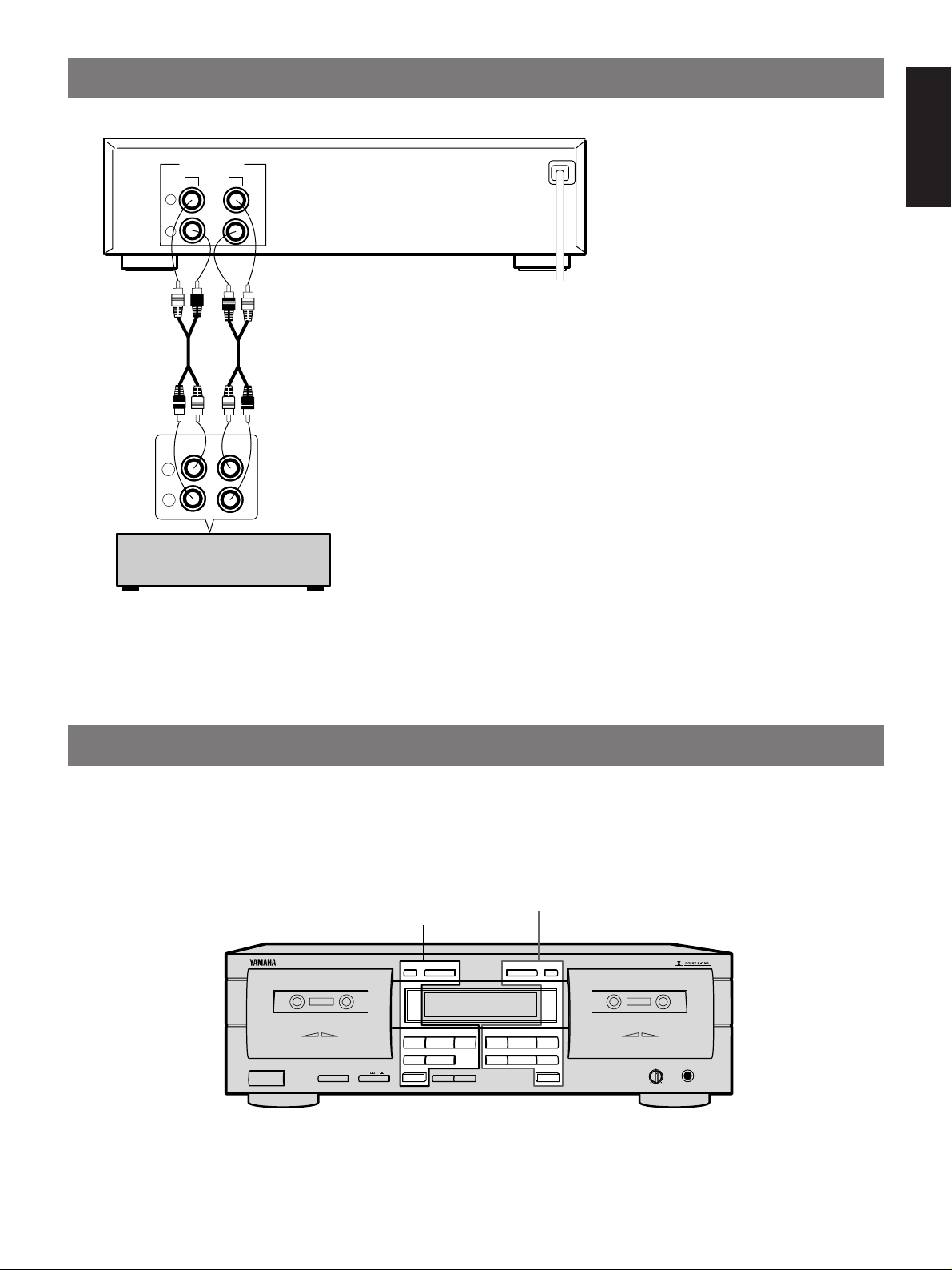
CONNECTIONS
ENGLISHFRANÇAISDEUTSCHSVENSKAITALIANOESPAÑOLDUTCH
(U.S.A. model)
To an AC outlet
REAR PANEL CONNECTIONS
Make sure that power to both the deck and your amplifier/receiver is turned off
before making any connections.
÷ The White plug on the paired connecting cables corresponds to the Left
channel and the Red plug corresponds to the Right channel. Make sure that
the left and right channel connections are properly made, and that the plugs
are inserted firmly.
÷ The LINE OUT/PLAY jacks on the deck should be connected to the TAPE PB
(Playback/Input) jacks on your amplifier/receiver, and the LINE IN/REC jacks
on the deck should be connected to the REC OUT (Recording/Output) jacks
on your amplifier/receiver.
÷ The LINE OUT terminals on this unit are numbered 3 and the LINE IN jacks
are numbered 4. When connecting this unit to a YAMAHA amplifier or
receiver whose terminals are numbered 1, 2, 3, 4 ... (etc.), connect this
unit's LINE OUT terminals to the input terminals numbered 3 and connect this
unit's LINE IN terminals to the output terminals numbered 4 on the rear panel
of the amplifier or receiver.
÷ Connect the power cord to an AC wall outlet or to an AC outlet on the rear
panel of your amplifier/receiver (if provided).
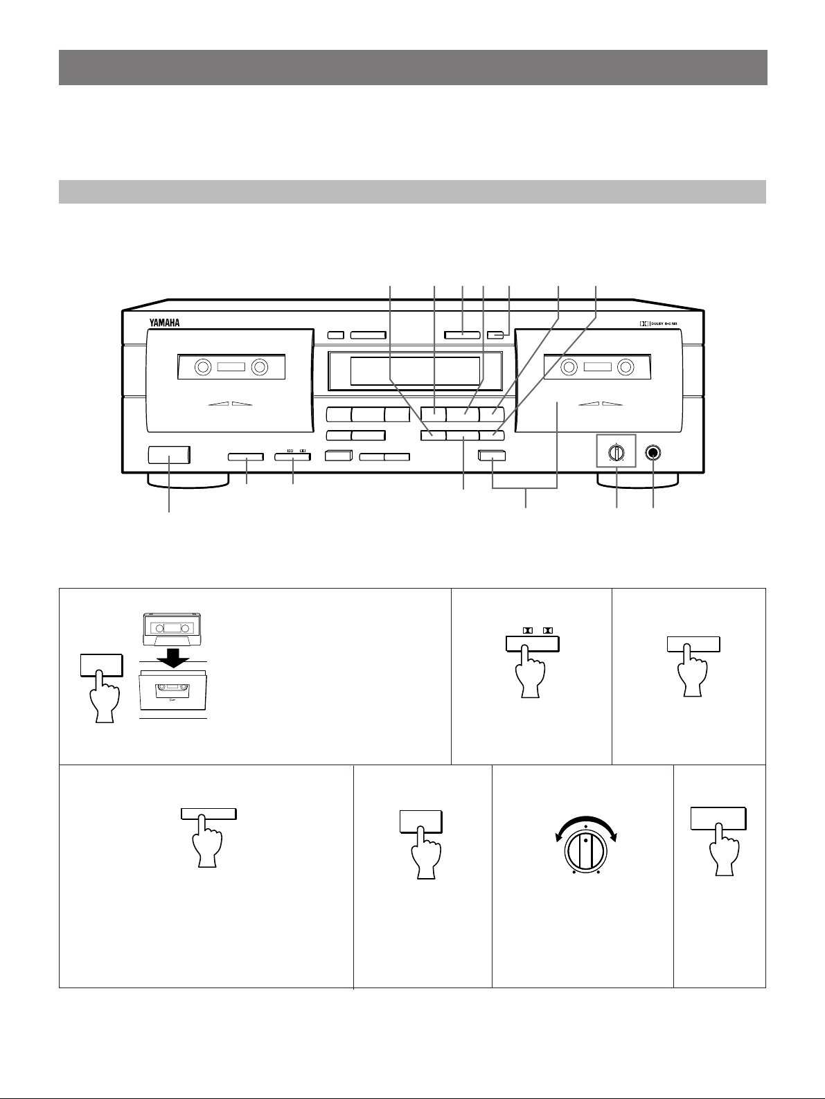
NOTES ON THIS MANUAL
In this manual, the main operation buttons of the front panel are indicated based on DECK B when the operation is common to
both DECKs A and B. Since the locations of the buttons of DECK A and DECK B are the same, you can easily find the desired
button even when operating DECK A.
Main operation buttons of DECK A
NATURAL SOUND CASSETTE DECK K-903
PLAYBACK
STANDBY/ON
O / p / ∏ / RELAY
MODE
CLOSE
DECK A
DOLBY NR
OFF/ B/ C
% %
! ⁄
&
SEARCH
EJECT EJECT
DUBBING A # B
NORMAL HIGH
Main operation buttons of DECK B
DIRECTION RESETRESET DIRECTION
PLAYPLAY
!⁄
&
MUTE/SEARCH
REC/PAUSE
CLOSE
RECORD/PLAYBACK
Stabilizer
CassetteStabilizerCassette
REC LEVEL
MIN MAX
DECK B
PHONES
5
PLAYBACK (Common to DECKs A and B)
Preparation for playback
÷ Turn on the STANDBY/ON switch.
÷ Set your amplifier or receiver to cassette deck function mode.
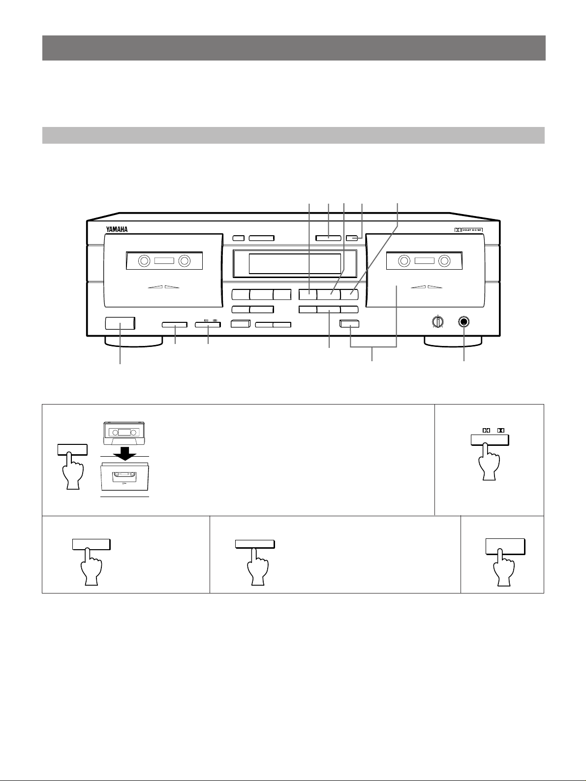
BASIC OPERATION - To play back a cassette tape
EJECT
NATURAL SOUND CASSETTE DECK K-903
PLAYBACK
STANDBY/ON
STANDBY/ON
RESET
&
EJECT
&
RESET
%
⁄
CLOSECLOSE
RECORD/PLAYBACK
StabilizerCassette
MODE
O / p / ∏ / RELAY
DECK A
DOLBY NR
OFF/ B/ C
23
%
RESET DIRECTION
SEARCH
! ⁄
PLAY PLAY
&
DUBBING A # B
EJECT
NORMAL HIGH
!
45
DIRECTION
!⁄
MUTE/SEARCH REC/PAUSE
1
Insert the cassette with the exposed tape side facing down. (The side
facing you is called the forward side and the opposite side is called the
reverse side.) To close the compartment, push the section of the
compartment door marked % CLOSE until it locks shut.
Cassette
Stabilizer
REC LEVEL
MIN MAX
21
DECK B
PHONES
PHONES
DOLBY NR
OFF/ B/ C
Refer to the following
description.
35
MODE
“/[/”/
RELAY
DIRECTION
4
Select the tape running direction for DECK A
PLAY
or B. Each time this button is pressed, the
Refer to the following
description.
tape running direction changes between
forward (#) and reverse (@), and the
corresponding indicator lights on the display.
To fast forward or rewind the tape
When the tape running indicator # is lit:
Pressing the ⁄ button fast forwards the tape while
pressing the ! button rewinds the tape.
When the tape running indicator @ is lit:
Pressing the ! button fast forwards the tape while
pressing the ⁄ button rewinds the tape.
To stop playback
Press the & button. To remove the cassette tape, press the
EJECT button. The cassette compartment door opens. To
set the unit to standby mode, press the STANDBY/ON
button.
To set the counter reading to “0000”
Press the RESET button. Use the tape counter to aid in
locating a point on a tape (0000 to 9999).
6
DOLBY NR selector setting (in step 2)
Be sure to set the DOLBY NR selector according to the
system used for recording.
OFF: For a tape recorded with DOLBY NR OFF.
B: For a tape recorded with DOLBY B NR.
C: For a tape recorded with DOLBY C NR.
:Both sides of the tape are played back. After
playing, the deck stops at the end of the tape.
(When the tape running direction is set to ¤, only
the reverse side is played.)
: Both sides of the tape are repeatedly played back
(up to 8 times).
ENGLISHFRANÇAISDEUTSCHSVENSKAITALIANOESPAÑOLDUTCH
REVERSE MODE selector setting (in step 3)
The auto reverse function allows the tape running direction
be reversed automatically. Select an auto reverse mode
(
(
, , or
).
) or manual reverse mode
RELAY
: When playback or fast forwarding (or rewinding) of
one side of a tape is finished, the deck stops at the
end of the tape.
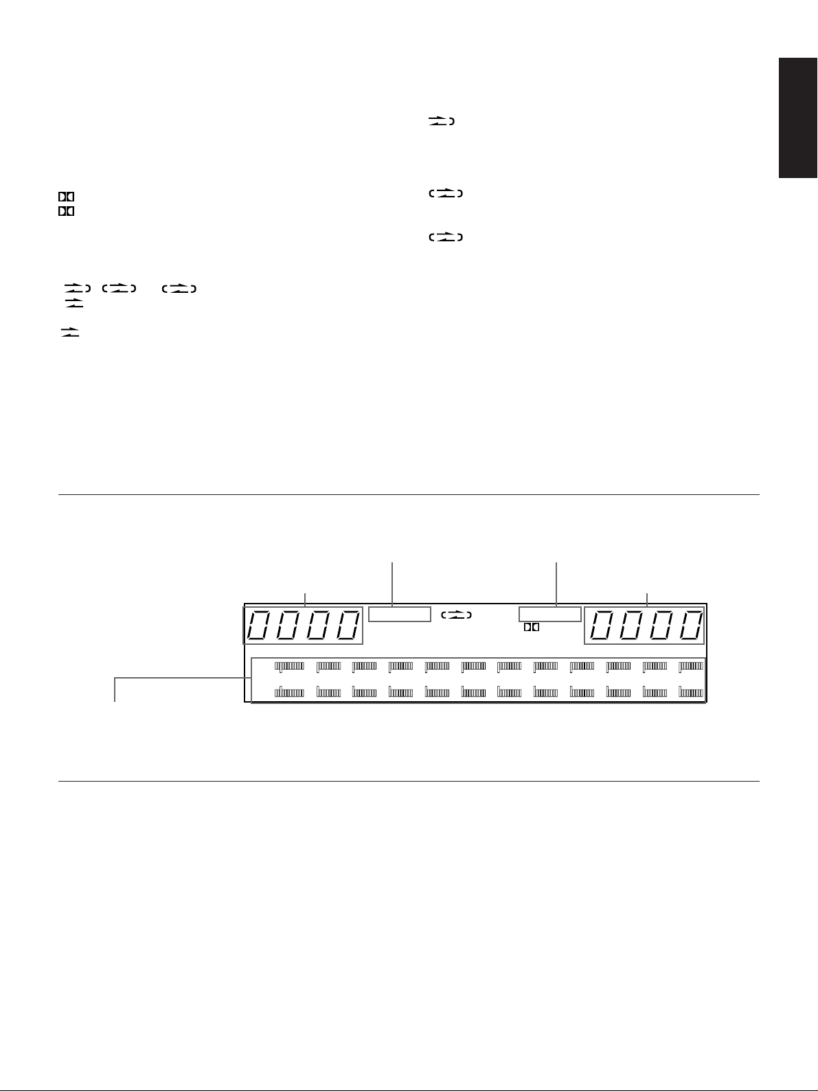
Display during playback
The A or B indicator shown in
the display represents the
last deck operated.
Tape counter
Tape running direction
indicator (DECK A)
RELAY
are played back sequentially. (See “RELAY
PLAYBACK” on page 9.)
¤
A
‹
DUB HIGH RECB C
RELAY
NORM
: Cassette tapes loaded in DECKs A and B
Tape running direction
indicator (DECK B)
Tape counter
¤
B
‹
L
—
30 dB
20 15 10 8 6 4 2 0 2 4 6
+
R
Peak level meters
Indicate the peaks of the signal levels during recording and playback over a –30 dB to +6 dB range. There are separate meters for each left
and right channel. These level meters have a peak hold function which holds the peak level for about 1.5 seconds.
To adjust the volume level
Use the volume control of the amplifier or receiver.
Note
Never press the EJECT button when the tape is in motion.
To use headphones
Insert the headphones plug into the PHONES jack. Since
the sound is also heard from the speakers, operate the
amplifier to cut off the sound from the speakers for private
listening.
7
MUTE/SEARCH
RESET
!⁄
NATURAL SOUND CASSETTE DECK K-903
PLAYBACK
STANDBY/ON
MODE
O / p / ∏ / RELAY
CLOSE
% %
DECK A
DOLBY NR
OFF/ B/ C
! ⁄
&
SEARCH
EJECT EJECT
DUBBING A # B
NORMAL HIGH
DIRECTION RESETRESET DIRECTION
!⁄
PLAYPLAY
&
MUTE/SEARCH
REC/PAUSE
CLOSE
RECORD/PLAYBACK
Stabilizer
CassetteStabilizerCassette
REC LEVEL
MIN MAX
DECK B
PHONES
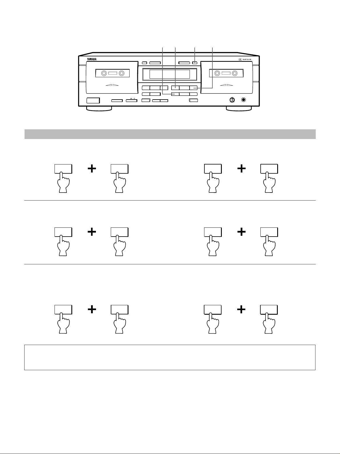
SELECTION SEARCH - To play back a desired selection by searching for the beginning of the selection
To search for the next selection
When the # tape running indicator is lit:
⁄
Press
simultaneously.
MUTE/SEARCH
To search for the beginning of the current selection
When the # tape running indicator is lit:
!
MUTE/SEARCH
When the @ tape running indicator is lit:
!
Press
simultaneously.
MUTE/SEARCH
When the @ tape running indicator is lit:
⁄
MUTE/SEARCH
Press
simultaneously.
Press
simultaneously.
To search for the selection located before the current selection
÷ Operate the following buttons when the beginning of the current selection is being played.
When the # tape running indicator is lit:
!
Press
simultaneously.
MUTE/SEARCH
When the @ tape running indicator is lit:
⁄
Press
simultaneously.
MUTE/SEARCH
Notes
÷ The blank interval between selections must be at least 4 seconds long.
÷ Selection search may not operate properly with tapes recorded at a low recording level or which have excessive noise.
8
NATURAL SOUND CASSETTE DECK K-903
CLOSE
% %
DIRECTION RESETRESET DIRECTION
CLOSE
ENGLISHFRANÇAISDEUTSCHSVENSKAITALIANOESPAÑOLDUTCH
PLAYBACK
STANDBY/ON
MODE
O / p / ∏ / RELAY
DECK A
DOLBY NR
OFF/ B/ C
! ⁄
&
SEARCH
EJECT EJECT
DUBBING A # B
NORMAL HIGH
PLAYPLAY
!⁄
&
MUTE/SEARCH
REC/PAUSE
RECORD/PLAYBACK
Stabilizer
CassetteStabilizerCassette
REC LEVEL
MIN MAX
MODE
RELAY PLAYBACK - To play DECK A and DECK B sequentially
Load the cassette tapes into DECKs A and B, start playback from DECK A.
The playback patterns differ according to the setting of the MODE button. Refer to the following.
When the MODE button is set to
RELAY
:
DECK A (forward side \ reverse side) \ DECK B (forward side \ reverse side)
5
Up to 8 times
When the MODE button is set to
DECK A (forward side \ reverse side) DECK B (forward side \ reverse side)
5
Up to 8 times
When the MODE button is set to
DECK A (forward side \ reverse side) DECK B ( forward side \ reverse side)
÷ When the tape running direction is set to ™, only the reverse side is played.
:
5
Up to 8 times
:
DECK B
PHONES
Display
RELAY
When the MODE button is set to
:
DECK A (forward side or reverse side) DECK B (forward side or reverse side)
9
RECORDING
Preparation for recording
÷ Turn on the STANDBY/ON switch.
÷ Set your amplifier or receiver to cassette deck function mode.
BASIC OPERATION - To record a program source
1
EJECT
NATURAL SOUND CASSETTE DECK K-903
PLAYBACK
STANDBY/ON
STANDBY/ON
MUTE/SEARCH
RESET DIRECTION
%
! ⁄
StabilizerCassette
MODE
O / p / ∏ / RELAY
DECK A
DOLBY NR
OFF/ B/ C
PLAY PLAY
&
SEARCH
DUBBING A # B
EJECT
NORMAL HIGH
23
Insert the cassette into DECK B with the
exposed tape side facing down. (The
side facing you is called the forward side
and the opposite side is called the
reverse side.)
To close the compartment, push the
section of the compartment door marked
% CLOSE until it locks shut.
47
RESET
&
EJECT
RESET
!
DIRECTION
!⁄
MUTE/SEARCH REC/PAUSE
&
2
Refer to the following
description.
%
CLOSECLOSE
RECORD/PLAYBACK
1
DOLBY NR
OFF/ B/ C
⁄
Cassette
5
Stabilizer
REC LEVEL
MIN MAX
6
DECK B
PHONES
PHONES
3
Refer to the following
description.
MODE
“/[/”/
RELAY
4
DIRECTION
Select the tape running direction.
(Press the DIRECTION button for DECK B.) Each
time the button is pressed, the tape running direction
changes between forward (#) and reverse (@), and
the indicator lights on the display.
10
5
REC/PAUSE
The REC indicator
lights on the display.
The deck enters the
Rec/Pause mode.
67
REC LEVEL
MIN MAX
Play the program source to be
recorded and adjust the
PLAY
Recording
starts.
recording level.
 Loading...