


.........
;""'
~
-~-tr::c';:}';.;··
..
:''= · •
YAMAHA
JT1---JT2
SERIES
· . · ·
.
SERVICE
MANUAL·
-

NOTICE
This manual has been written by Yamaha Motor Company for use by Authorized Yamaha
Dealers and their qualified mechanics.
certain basic mechanical precepts and procedures inherent to our product are a'lready
In
light of this purpose it has been assumed that
known and understood
Without such basic knowlege, repairs or service to this model may render the machine
unsafe. and for this reason
by
an
Authorized Yamaha dealer who
knowledge. Other information is produced by the
Corporation. and
The Research. Engineering. and
further improve all models manufactured by the company. Modifications are therefore
evitable and changes
Yamaha Dealers and will. where applicable. appear
by
the reader.
we
must advise that all repairs
is
in
possession of the requisite basic product
U.
is
necessary to provide total technical coverage regarding the product.
Service
in
specifications or procedures will be forwarded to all
YAMAHA
JT
1st
EDITION,
2nd
Departments of Yamaha are continually striving to
in
SERIES
EDITION,
SERVICE
DECEMBER 1973
MAY
and/or
S. distributor. Yamaha International
future editions of this manual.
service be performed
Authorized
MANUAL
1976
in-
i
f
©DECEMBER
1973
YAMAHA
BUENA
INTERNATIONAL
PARK,
CALIFORNIA
LIT-11612-88-99
CORPORATION
90620
. '
~·
.
'
FOREWORD
The new
Yamaha Endure
suspension
Its
exRerienced
This service manual
techn1c1ans
in
this goal.
YAMAHA
combine
rugged design
riders
the repair
top
cond1t1on
vein.
We
MINI
ENDURO. though small
The
60
cc engine. four. speed gearbox. tubular frame
to
provide
and
excellent performance also make it
as
well.
has
1nstruct1ons
hope that
been
an
ideal
vehicle
prepared
you
1n
order to provide all Yamaha dealers
and
technical information required
will find this manual most helpful
for
in
the
size.
younger
is
a fully functional motorcycle
and
rider.
an
intriguing
d1vers1on
to
keep
and
for older. more
and
the
valuable
MINI-ENDURO
in
the
fully functional
their service
in
carrying out
YAMAHA MOTOR CO., l TD.
ENGINEERING & SERVICE DEPARTMENT
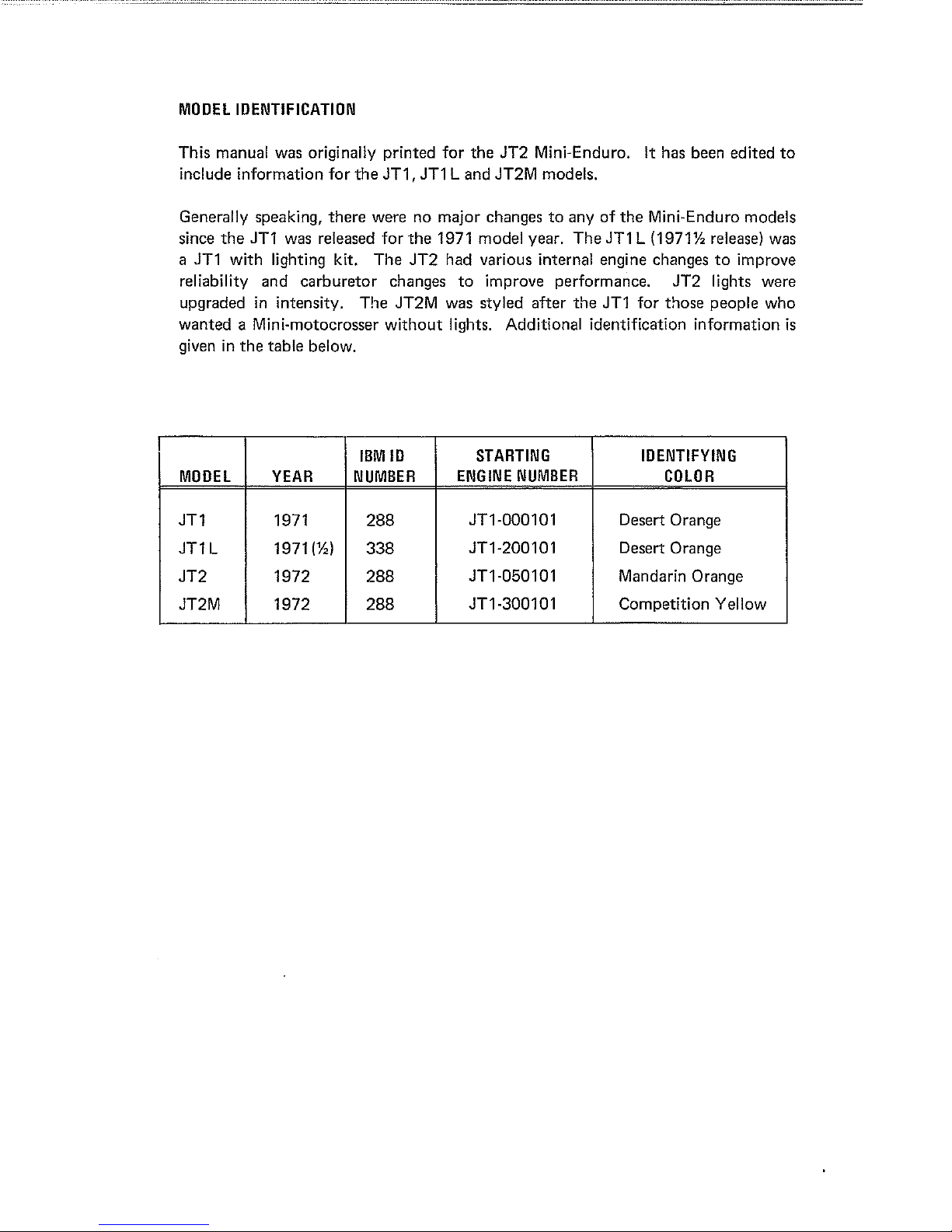
MOOEL
IDENTIFICATION
This manual was originally printed for
include information for
Generally speaking,
since
the
JT1 was released
a JT1 with lighting kit.
the
JT1,
JT1
there
were no major changes
for
the
1971 model year.
The
JT2
Land
had various internal engine changes
reliability and carburetor changes
upgraded
wanted a Mini-motocrosser
given in
MOOEL
JT1
JT1 L
JT2
JT2M
in
intensity. The JT2M was styled after
the
table below.
YEAR
1971
1971(½)
1972
1972
without
IBM
ID
NUMBER
288
338
288
288
lights. Additional identification information
ENGINE
the
JT2
Mini-Enduro. It has been edited
JT2M models.
to
any
of
the
Mini-Enduro models
The
JT1 L (1971½ release) was
to
improve
to
improve performance.
the
JT1 for those people who
STARTING
NUMBER
JT2
lights were
IDENTIFYING
COLOR
JT1-000101 Desert Orange
JT1-200101 Desert Orange
JT1-050101 Mandarin Orange
JT1-300101 Competition Yellow
to
is

CONTENTS
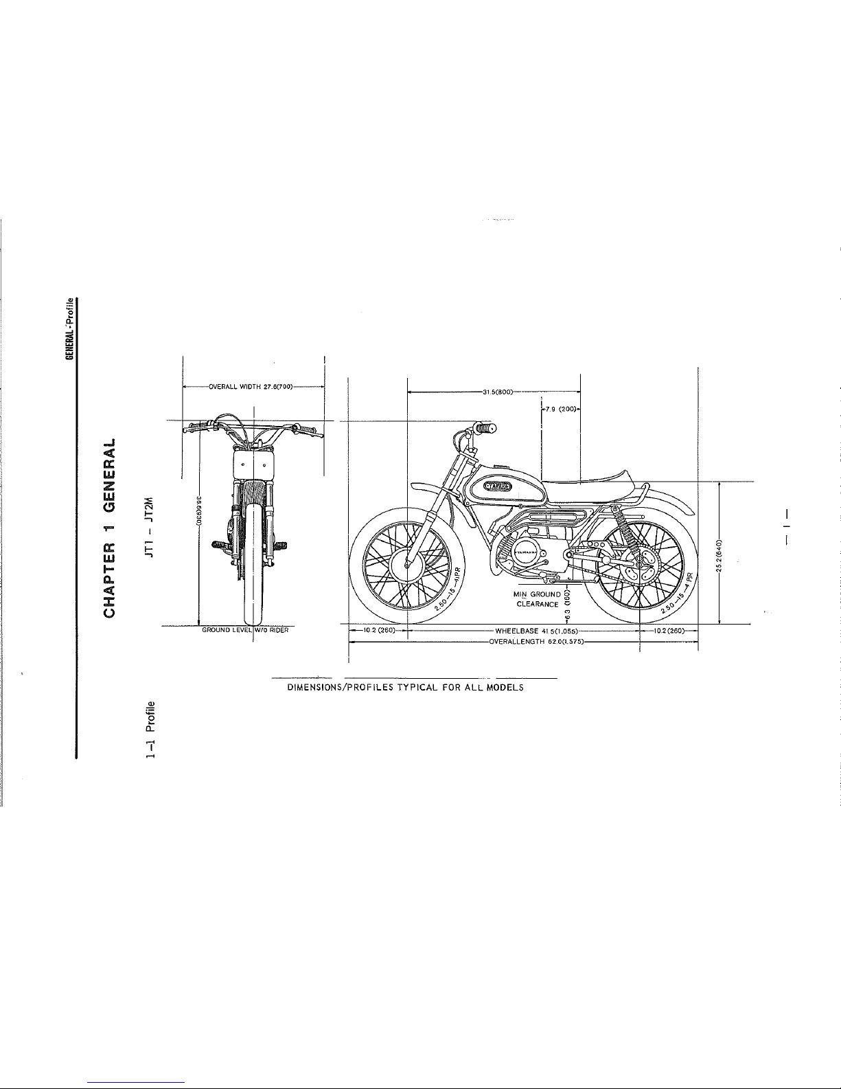
CHAPTER 1 GENERAL
1-
1 Profile ··············································································································--···--·--··
1-
2 Features ··--··--···----·--········--···--·--·················--·--·--·--·--·--················································ 2
1 - 3 Specifications and Performance ·----·--·············································--·--------·------·--··--·--· 3
1 - 4 Performance Curves ·······················--·· ··--··--······--···--····----·--·--····································· 5
1 - 5 Tools and Instruments for shop service ··································--··--·--···--··------·--·---------- 6
CHAPTER 2 YAM
2 - What
2-
2 Features of Yamaha Autolube --··----------··--···--···················--·----------------·--·--··--··----·--··· 7
2 - 3 Handling
CHAPTER 3 ENGINE
3 - Engine
3 - 2 Cylinder Head ···········································--··------------------------···----····----······················
3-
3 Cylinder ·······················--···········································--·--·----·--·--··--······················--······
3-
4 Piston
3 - 5 Piston Ring ·········--·········--·--·--································--····----------------··--···························
3 - 6 Piston ----·--·--·······--·--·--·--·······--······--··· ·········································----·--·----·········· ..........
3 - 7 Flywheel Magneto ···································--·--·----··--------··----·--·--·--··········--········----·------·
3-
8 Crankcase Cover (RH)·····························--·--·--------------·--·--···························--··--·----
.................................................................................................................... .
AHA
AUTOLU
is
Yamaha Autolube? --------------------------···························---------------------------------- 7
the
BE
·--·----·--------·----·--·----······
Oil Pump --------------··------------------··----·························----··--------------------·-- 7
·················--·--··--·--·------····--··------·--·--······ 7
·························································-------------------- ----···································· 1 I
Remova1
Pin
----------------------------------···--······································----··------------·--------·· I 1
--··········--······--··················--···--············--·--·------------·------··--··························· 17
15
16
18
19
20
21
3-
9 Clutch ············································----·--·--·--··--·······--······················--····--···--··--····--·--··· 22
3-10
3 -
3-12
3-13
3 3 3
3 - 17 Crankshaft ·--··--··--·········--········································--··----·······························--·--·----····
3-18
Primary Drive Gear··················--····--·····················--·--------------·························--·--·----· 27
11
Kick Starter Mechanism ·····································----------··--·--···················--·----------··---- 27
Shift Mechanism ----·············--···································--------------························--·------··-Rotary Valve····--·····--········································--······------····························------········ 31
14
Drive Sprocket ················································--······----------·····························--··----····
15
Crankcase --·--························--·········----------------·----------··························--------------·--·····
-16
Transmission Assembly ----·····--·--······································--------------------··················----
Bearings
and
Oil
Seals
.............................................. --·······················----········----······· 41
-3-19 Carburetor ····--·····--·························--··········--·············--·--·················------·--·····--·--········
29
33
35
36
38
42

3 - 20
Air
Cleaner ................................................................................................................ 44
CHAPTER
4
CHASSIS
4-
1 Front
4-
2 Rear
4-
3 Rear Wheel Sprocket ............................................................................................... 53
.................................................................................................................... 46
Wheel
Wheel
.............................................................................................................. 46
............................................................................................................... 49
4 - 4 Tires and Tubes ........................................................................................................ 54
4-
5 Front Forks ............................................................................................................... 54
4-
6 Rear Shocks ............................................................................................................. 57
4-
7 Gas Tank .................................................................................................................. 58
4 - 8 Rear Swing
Arm
...................................................................................................... 58
4 - 9 Steering Head ........................................................................................................... 60
4-
10
Oil
Tank and
4 -
11
Frame ........................................................................................................................
4 -
12
Handlebars ................................................................................................................
Tool
Box............................................................................................
'
4-13Miscellaneous ............................................................................................................
CHAPTER
5
ELECTRICAL
5-1 Electrical
5-
2
List
of
Electrical
5-
3 Ignition System-Function and Service .......................................................................... 63
5-
4 Ignition
5-
5 Ignition
5-
6 Condenser
5-
7
Charging
5·
8 Battery ............................................................................
5-
9 Checking the
5-
10
Spark
Plug
SYSTEM
............................................................................................... 62
Equipment..................................................................................................... 62
Components ..................................................................................... 62
Timing
Coil
..
.........................................................................................................
..... ........................................................................................................... 64
..
. .
... . .. .. ..
..
. . .
... ... ... ... ...
......
...
....
... ... ... ... ... ...
.. . ...
..
... . ... . ..
..
. . . . .....
...
..
. .
..
System...........................................................................................................
•···· • •··
• •
•· • •···
• • •
•··
•···
•·
•·····
main
Switch .............................................................................................
.......................................................................................................................
....
· · ·
...
··
..
...
····· · ·
61
61
61
61
63
. .
64
65
67
69
69
APPENDICES
..................................................................................................................
I Parts
II
Ill
IV
V
VI
and
Service
Bulletins..................................................................................
Parts Illustrations..............................................................................................
Maintenance
Pre-operation
Torque
Cleaning
Metric
Values
and
Inch
and
Lubrication
Check
for
Storage
Conversion
Intervals....................................................................
List....................................................................................
Common
Components...................................................................
Hints
.............................................. .................................
Tables..............................................................................
72
72
82
86
87
87
..
88
89
:E
0
d:
'•
m
i5
"'
..I
ct
a:
w
:z
w
w
:::.
a
"
C,
"'
<)
I-
w
..,
8
....
a:
I-
w
..,
I-
a.
ct
::c
(.)
..!!!
~
c...
7'
.....
OVERALL
WIDTH
27.6(700)---I
GROUND
LEVELIW/0
RIDER
i---------31.5(800,\------------<
'
r7-9
(200)
'
M
"'
) WHEELBASE
41
5{1.055) I
----j
>----------------<JVERALLENGTH
62.0(1.575)>------+-----4-,
DIMENSIONS/PROFILES TYPICAL
FOR
ALL
MODELS
0
~
e
N
,ri
N
I
"
I
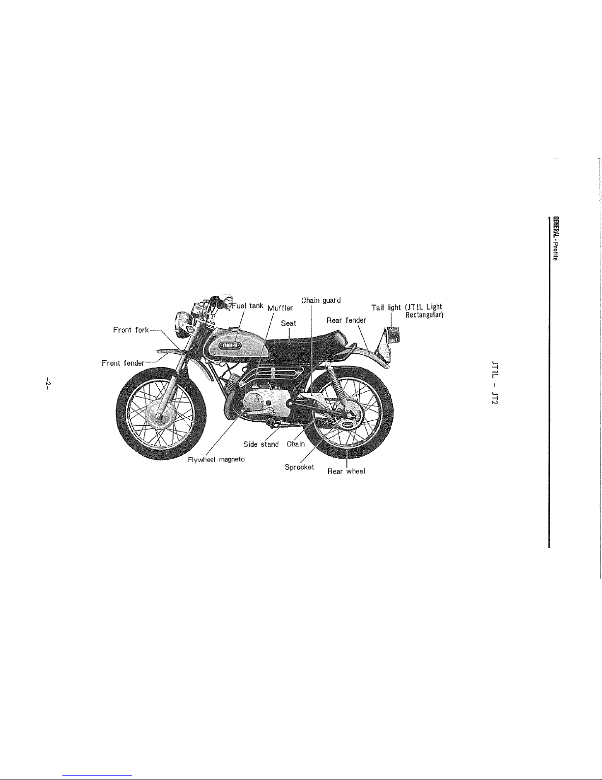
Front fork
Chain
guard
Muffler
Side stand
magneto
Sprocket
Rear
wheel
Tail light (JT!L
Light
Rectangular)
<...
-I
~
r
<...
-I
"'
"'
!1c!
i
,,
~
;,
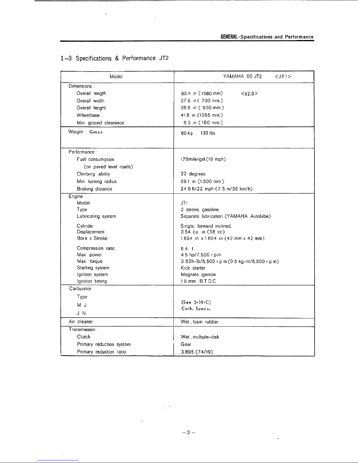
1-3
Specifications & Performance
JT2
GENERAL-Specifications
and
Performance
Model
Dimensions .
Overall length
Overall width
Overall height
Wheelbase
Mm
ground clearance
Weight,
Performance ·
Engine
Grr:iss
Fuel consumption
(on paved level roads)
Climbing ability
Min. turning radius
Braking distance
Model
Type 2 stroke,
Lubricating system Separate
Cylinder
Displacement
Bore x Stroke 1
Compression
Max
Max
Starting system
Ignition system Magneto
Ignition timing
Carburetor
ratio
power
torque
Type
M J
J N
Air cleaner
Transmission
Clutch
Primary reduction system
Primary reduction ratio 3.895
I
YAMAHA
62.4
in
( 1580 mm)
27 6 ,n (
366
41.5
60
63
kg
,n (
,n
,n
700
930
(1055
(160
1321bs
mm
mm)
mm)
mm)
)
176m1le/9al (19 mph)
22
degrees
59.1
24
in. (1,500
6
ft/22
mm)
mph
(7 5 m/35
JT1
gasoline
lubricahon
Single. forward inclined.
3,54
654
6.4
1
cu
,n
in
x 1
(58
654
(YAMAHA
cc)
in_
(42
4.5 hp/7.500 rp.m
3
62ft-lb/5.500 r p.m
Kick starter
1gmt1on
18
mm
BTD.C
(See
3-19-C)
Corb.
Specs.
Wet .
foam
rubber
. multiple-disk
Wet
Gear
(74/19)
60
JT2
<62.0>
km/h)
Autolube)
mm
x
42
mm)
(0 5 k9-m/5.500
<JTI>
rpm)
-3-

GENERAL-Specifiaations
and
Performance
Model
Gear
box
Type Constant
system.
system.
1st
2nd
3rd
4th
front
front
front
Reduction ratio
Secondary reduction system
Secondary reduction ratio
011
capacity
Chassis
Frame Tubular-Double loop
Suspension
Suspension system. rear Swmging arm
Cushion system
Cushion system. rear
Steering system
Steering angle
Caster
Tra1!
Brakmg system
Type of brake
Operation
Operation system. rear
Tire size
Front
Rear
Dynamo
Model
Manufacturer
Tanks
Gasoline tank capacity
011
tank capacity
3077(40/13)
1.889
I
1.038
Chain
3153(41/13)
0.85
T
elescop1c
Coil
Coil
4 7° both right
63
2 7 in
Internal expansion
Right
Right foot operation
2
2
F11-L46
HITACHI
11
11
mesh,
(34/18)
304 ( 30/23)
(27/26)
US
qts
sprmg. oil damper
sprmg,
5°
(68mm)
hand
50-t5-4PR
50-t5-4PR
ltd
gals(43/)
us
us
qts (1.0
YAMAHA
4-speed forward
(800-850
fork
011
damper
and
left
operation
<Fl
I)
60 JT2
cc)
1-L42>
-4-

1-4
PERFORMANCE
60
JT
5
ENGINE
I I
Maximum
Ma;ii;imum
CURVES
PERFORMANCE
4.5
3.62
I
B
1-P
Power
Torque
CURVES
I I
/7,500
rpm
ftlbs/5,S00rpm
Horse power
I
GENERAL·
Performance Curves
w
IQ
0
:i:
/
\
'
/ \
I'--..
\
',
'
\
w ~
:,
.
0
"'
3
"'
I
0
"'
...
-
2
~
I
r
I
I
Torque
------
........_
3
V
/
I
z
0
500
400
300
ii'
"
~
::,
i
~
~
8
~
J
~
~
View
I
/
'"'
2,000
----
3.000
Fuel consumption
4,000
5,000
ENGINE SPEED
6,000
7,000
8,000
(rpm)
3-port Cylinder
--
9,000
Exploded
-
10,000
(~-ti~)_
-N-/----<,----'---'--/---';-----''------\._
I I
-------
Exhaust port t ran sf er
22.0
24.0 \
---------
0
N
"'
":
~
"'
l , I
--------
- 5 -
par
19.5
0
"'
I
)
I
·~
-
'
__
Inlet port
-
,._,.
I
,_
____
1l
,~---~'---
"'
<D
~
0
~
<D

GENERAL-Tools
1-6
Tools
The
following
1
General
Tools
and Instruments for Shop Service
and
Instruments for
tools
and
instruments
1) Plug wrench 23x29
2)
A set
of
3) A set
4)
Plastic tip
5)
Steel
6)
Circlip pliers
7)
Circlip pliers
8)
Needle
9)
Pliers
10) Phiilips-head screwdriver
It)
Phillips-head
12) Phillips-head screwdriver (M)
13) Phillips-head screwdriver (S)
wrenches
of
socket wrenches
hammer
hammer
(ST
(RT
nose
pliers
screwdriver(l)
Shop
are
required to service
mm.
type)
type)
14) Slot-head screwdriver(M)
15) Slot-head screwdriver
16) T-handle socket
(S)
wrench
Service
Fig 1-6-1
the
JT2
2
Special
In
addition
3 Other
Tools
and
Instruments
I Clutch holding
2 Crankcase disassembling
3 Crankshaft
4 Flywheel
5 Flywheel
an
electro-testor, tachometer.(engine
Material
1)
Yamaha Bond (No.5)
2)
Gear
3)
Grease
4) Wiping material
5)
Yamaha Bond No.4
6)
Wood0J1
7)
Oiler
8) Oil jug
assembling
magneto
magneto
011
box
tool
tool
holding
puller
tool
tool
rpm
F,g
t-6-2
meter)
hy..drometer
,etc. should
and
available.
The
use
of a wooden
photo
will facilitate
Consumable
ment
parts
parts
must
(such
also
box
engine
as
be
as
shown
service
gaskets)
on
hand.
in
and
and
the
above
overhaul.
replace-
-6-
Fig.
1-6-3

YAMAHA
AUTOLUBE·What
is Yamaha
Autolube?
Features of Yamaha Autolube, Handling of the Oil Pump
CHAPTER
(
Automatic,
2
-1
What
is
Yamaha
Conventional 2-stroke engines are lubricated
mixed
in
gasoline. but
automatic, separate lubrication system, That
in
a separate oil tank
oil
pump
and
fed
to
speed
and
load
Autolube?
YAMAHA
is
the
·s
Autolube furnishes
automatically regulated
engine
according
2
YAMAHA
Separate
by
oil pre-
an
1s.
the oil
by
the
to
engine
AUTOLUBE
lubrication
YAMAWI
AlJTOLUBE
OIL
•.
iiij;~
Fig 2-1-1
Sys
STRAIGHT
tern)
~IN£
2-2
Features
The
oil
pump
which
in
turn
according to engine speed and throttle valve opening, thus pumping the optimum amount of oil for
under any operating condition.
This "automatic. separate lubrication" does not merely eliminate disadvantages
11
further improves the perform,,nce and efficiency of
which formerly existed
The
Autolube feeds
featuring .
1s
dnven
is
controlled
of
Yamaha
Autolube
by
the
engine
through a reduction gear
by
the
occellerotor grip The
an
optimum amount of lubricating oil to the engine under any operating condition, thus
oil
2-stroke
,and
is
connected
pump
automatically regulates
designs by eliminating certain oil-starvation conditions
to
the
in
the conventional
carburetor throttle
the
volume
* Less oil consumption
* Less carbon accumulation
* Less exhaust smoke
* Improved lubricating efficiency.
2
The
Auto[ube simplifies fuel supply. thus featuring:
* Using straight gasoline directly
in
the gas
tank
* Less fuel contamination.
3 The Auto!ube improves the reliability of lubrication. thus eliminating.
* Special care concerning oil/fuel mixing ratios.
2
-3.
Handling the
The oil pump is a precision-machined assembly.
from the engine. protect
handling will keep the pump free from trouble.
Oil
Pump
Make
no
attempt to disassemble
1t
from dust dirt. ·etc,. and after reinstalling lt. bleed and adjust the pump correctly. Proper
it.
When
you
remove the oil pump
of
engi_ne
pre-mix
cable,
lubricating oil
!ubncation
system. but
-7-
YAMAHA
AUTOLUBE·Handling
of
the
Oil
Pump
The oil pump is similar
ment
of
a
4,0
in
¢ plunger.
both construction
and
operation to other Autolube
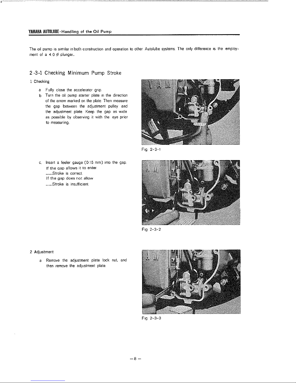
2-3-1 Checking Minimum Pump Stroke
1 Checking
a Fully close
b Turn the oil pump starter plate in
of the arrow marked
the gap between the adjustment pulley and
the adjustment plate. Keep
as
possible
to measuring,
c.
Insert a feeler gauge
If
the
...... Stroke
If
the
...... Stroke
qap
gap
the
accelerator grip.
on
by
observing lt with
(015
allows it
Is
does
is
to
correct
not allow
insufficient
the
direction
the plate. Then measure
the
gap
as
the
eye prior
mm) into
enter
the
wide
gap
Fig 2-3-1
systems.
The only difference
is
the
employ-
2 Adjustment
a Remove
then
the
remove
adJustment
the
adjustment plate
plate lock
nut.
and
-8-
Fig
Fig
2-3-2
2-3-3
YAMAHA
AUTOLUBE·Handling of the
Oil
Pump
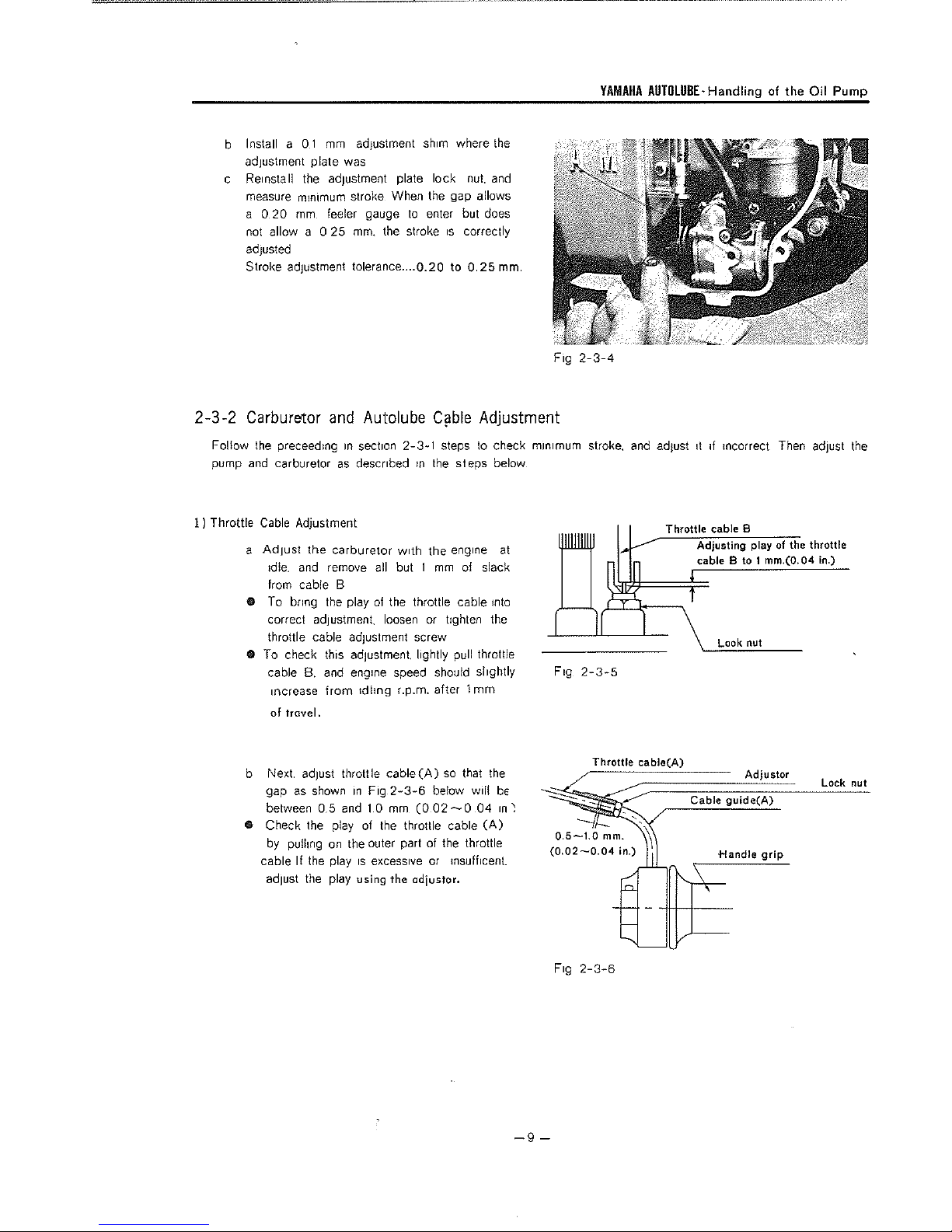
b Install a O 1
adJustment plate was
c Reinstall
measure minimum stroke When the gap allows
a O 20
not allow a O 25
adiusted
Stroke adJustment tolerance .... Q.20 to
2-3-2
Follow
pump
Carburetor
and
I I Throttle
a AdJust
9 To bring
• To check this adiustment lightly pull throttle
mm
adiustment shim where the
the
adjustment plate lock
mm,
feeler gauge
mm.
and
the
preceedmg
carburetor
Cable
Adjustment
td!e.
from
correct adJustment. loosen or tighten the
throttle cable adiustment screw
cable
increase
in
section
as
described m the
the
carburetor
and
remove all but 1
cable B
the
play
B.
and engine speed should slightly
from
1dlmg r.p.m. after 1
to
the stroke
Autolube
2-3-1
with
of
the throttle cable into
nut.
enter but does
1s
correctly
0.25
CiJble
steps
steps
the engine
mm
of slack
of travel.
and
mm.
Fig
Adjustment
to
check minimum stroke.
below
at
Fig
mm
2-3-4
2-3-5
and
adJust
Throttle
11
1f
incorrect Then
cable
8
Adjusting play
cable
B to 1 mm,(0,04 in.)
Look nut
of
the throttle
ad1ust
the
b Next.
adJust
gap
as
shown
between 0,5
throttle
in
Fig
and
1 0
cable(A)
2-3-6
mm
(0
so
be!ow
02
,..__,0
that
e Check the p!ay of the throttle cable
by
pu!hng
on
the outer part of the throttle
cable If the play
ad1ust
the play using the odiustor.
1s
excessive or
msuff1cent.
w1!!
04
the
(A)
bE
in~
-9-
Fig
Throttle
2-3-6
cable(A)
Cable
Adjustor
guide(A)
+-landle
Lock nut
grip

ENGINE·
2)
Handling
Autolube
of
the
Cable
Oil
Pump
Adjustment
With the throttle cable properly adjusted, check the pump
guide pin location. It should be no closer
(.060")
close, loosen
adjusting bolt until adjustment
to
the raised boss
the
lock
of
the pump pulley.
nut
(see Figure 2-3-7) and
is
correct.
than
If
it
turn
Tighten
lock nut.
1.5mm
is
too
the
Lock
nut
Next, turn throttle
to
full open position, the guide pin
should not strike the raised boss
position,
if
it does, loosen the adjusting bolt slightly
provide clearance.
2-3-3
Bleeding
When
the
pump
has
been removed or the Autolube oil
an
irregular flow
ular flow of oil.
I ) Remove the bleeder bolt.
of
oil
after
b'
leed the pump
the
of
the pump pulley
pump
1s
mounted again
in
the
following manner
or
in
has
the
this
to
run
01!
Fig
2-3-7
out.
air will enter the pump. The air will cause
tank
1s
refilled
In
order
to
prevent such
an
irreg-
Guide
pin
2)
Next. rotate
the arrow marked
mg
011
and
this
and
stroke becomes greater, the air can
the
starter plate
on
the
plate until
tighten the bleeder bolt To facilitate
bleeding,
rotate!
no
fully
open
the
starter plate. As
in
the
the
plate. Continue turn-
air comes out with
the
accelerator
bled.
direction of
the
grip
the
plunger
be
quickly
-10
Fig
Fig 2-3-9
-
2-3-8

ENGINE-Engine Removal
CHAPTER
This chapter
service data. However, except when overhauling
and oil seals
save a lot
Preparation
1)
All
before removal and disassembly. This will prevent
engine assembly.
2)
Before engine removal
form a clean
3)
During disassembly of the engine
assembly time faster and easier,
3
-1
c;lescribes
in
of
time
dirt.
mud,
Engine
Start the engine
then
turn off the engine and drain the transmission
oil
the disassembly and reassembly of the engine, its removal from the chassls, and the necessary
the crankcase, it
and
labor.
for
disassembly
dust.
and
·efficient job.
and
and
is
suggested that engine
of the engine :
foreign
material
disassembly,
..
clean all parts and place them
and
insure correct installation of all engine parts.
Removal
and
warm it up for a few
3 ENGINE
the
crankshaft assembly, transmission, shifter mechanism or bearings
be
should
be
sure
.minutes,
serviced without removing
be
thoroughly
any
you
have
removed
harmful foreign material from entering the interior of the
proper tools and cleaning equipment
in
trays
from
in
it
from the chassis. This will
the
exterior
of
the
engine
so
order of disassembly. This will make
you
assembly
can
per-
(Volume of o;I
2 Pull out the seat fitting
by pulling
it
800-850
YAMALUBE
SAE
lOW-30
backward.
cc
10.85
US
4-CYCLE
or
"SE"
pin
and remove the seat
qt)
Fig
Fig
3-1-1
3-1-2
-11-
ENGINE·
Engine
Removal
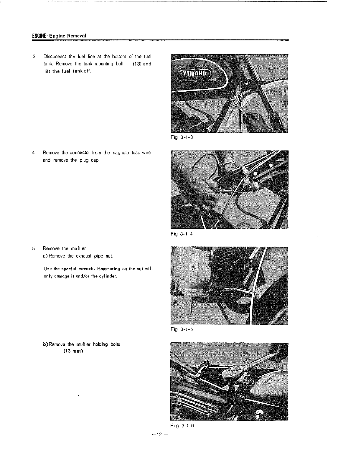
3 Disconeect
tank.
Remove
lift
the fuel
4
Remove
and remove the plug
the connector from
the
the tank
tank
fuel
off.
line
mounting
cap,
at
the
the
bottom of the
bolt (13) and
magneto
lead
fuel
wire
F,g
3-1-3
5
Remove
a)
Use
only damage
Remove
the
the muffler
special
b)Remove
(13
the
exhaust pipe
wrench. Hammering on
it
and/or
the
cylinder.
the
muffler holding bolts
mm)
nut.
the
nut will
Fig
Fig
3-1-4
3-1-5
-12-
Fig
3-1-6
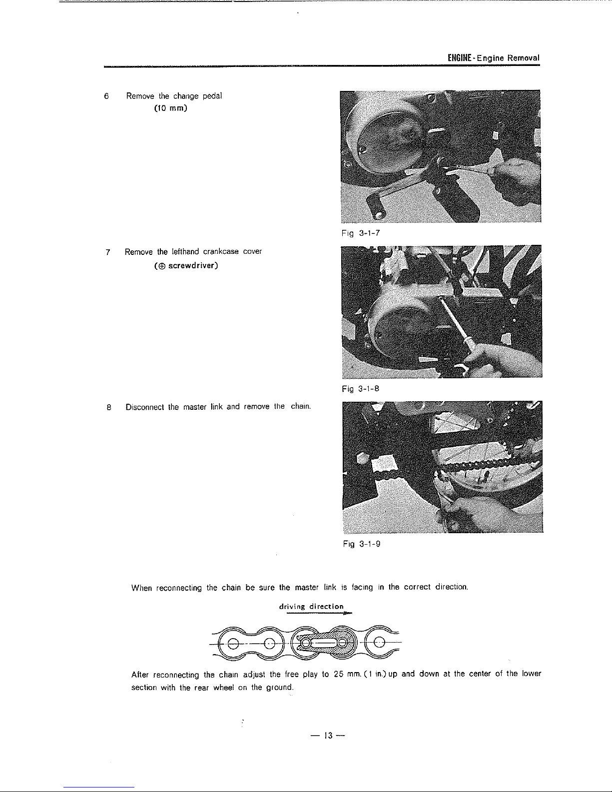
6
7
Remove
Remove
the
change pedal
(10
mm)
the
!efthand crankcase cover
($
screwdriver)
Fig
ENGINE-Engine Removal
3-1-7
8 Disconnect the master link and remove the
When reconnecting the chain be sure the master link
driving
After reconnecting the chain adjust the free play to
section
with
the rear wheel
on
the ground.
chain.
direction
Fig
3-1-8
Fig
3-1-9
is
facing
in
the correct direction.
25
mm.
( 1 in.) up and down at the center
of
the lower
-13-
ENGINE-Engine Removal
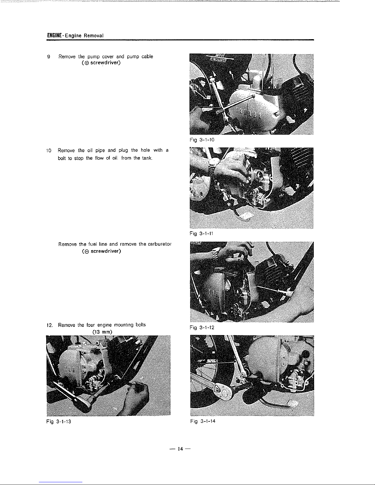
9
10
Remove
Remove
bolt
to
the
((£)
the
stop
pump cover
screY_tdriver)
oil
pipe
the
flow
and
of
and
plug
oil.
pump cable
the
from
the
hole
tank
Fig 3-1-10
with a
12.
Remove
Remove
the
fuel line
(8
the
four engine mounting bolts
and
screwdriver)
(13 mm)
remove
the
carburetor
Fig
3-1-11
Fig 3-1-12
Fig 3-1-13
Fig 3-1-14
-14-
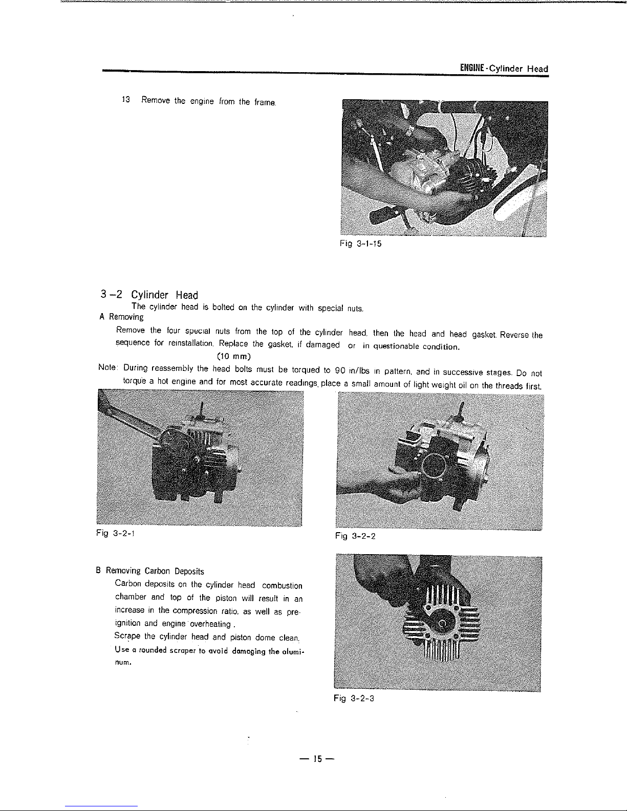
13
Remove
3
-2
Cylinder
A
Note: During reassembly the head bolts must be torqued
The cylinder
Removing
Remove
sequence for rernsta!lation, Replace
torque a
the
hot
the
Head
four
engine
engine
head
special
from
the
frame.
is
bolted
on
the
cylinder with special
nuts
from
the
top
of
the
the
gasket. if damaged or
(10
mm)
and
for
most accurate readings_ place a small amount of light we;ght oil
cylinder
to
90
Fig 3-1-15
nuts.
head,
then
in
questionable condition.
rn/lbs
rn
the
head
pattern, and
ENGINE·
Cylinder Head
and
head
gasket
Reverse
in
successive stages. Do not
on
the threads first.
the
Fig 3-2-1
8
Removing
Carbon
chamber
increase
ignition
Scr~pe
Use
o rounded
num.
Carbon
deposits
and
in
the
and
engine
the
cylinder
Deposits
on
the
top of
the
compression
overheating
head
scraper
to ovoid damaging
cylinder
piston
ratio,
and
head
will
as
.
piston
combustion
result
well
as
dome
clean.
the
in
an
pre-
olumi•
-15-
Fig
Fig
3-2-2
3-2-3
ENGINE·
Cylinder
3-3
Cylinder
A
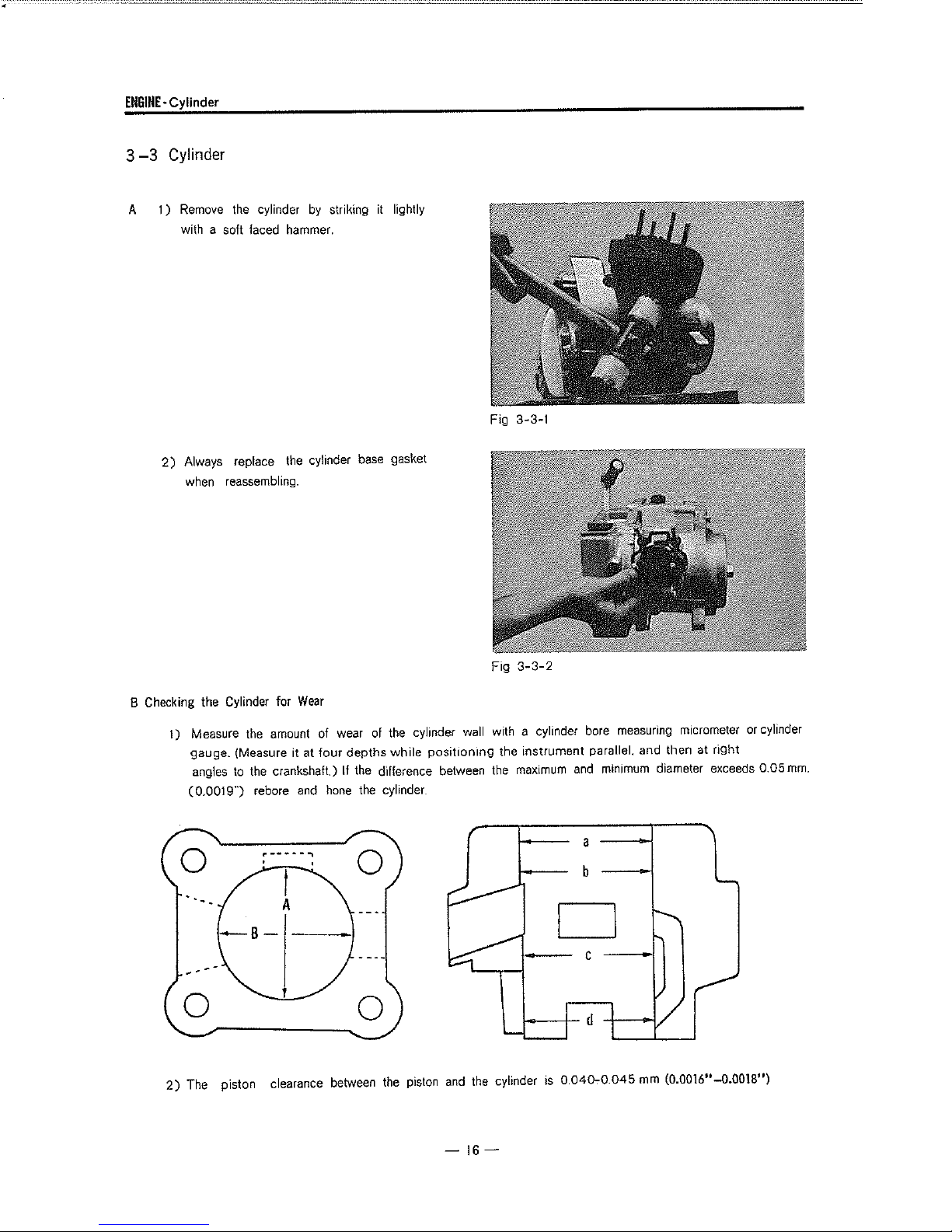
1)
2)
Remove
with a soft faced hammer.
Always replace
when reassembling.
the cylinder
the
by
cylinder
striking
base
it
gasket
lightly
Fig 3-3-1
8 Checking the Cylinder for
1) Measure
gauge. (Measure it at
angles
(0.0019")
the
amount of wear of the cylinder wall with a cylinder bore measuring micrometer
to
the
crankshaft) If the difference between the
rebore
0
-s-
--
0
---------....
2)
The piston clearance between
Wear
and
four
hone
depths
while
the cylinder
0
the
Fig
3-3-2
posit1on1ng the instrument parallel. and then at riQht
maximum
and
minimum
diameter exceeds 0.05
a
b
D
-c
piston
and
the cylinder
1------1'-
d
is
0.040-:-0.045
mm
(0.0016"-0.0018")
or
cylinder
mm.
-
16-

C
Cylinder
ENGINE-Cylinder, Piston Pin
Reconditioning
1) Pistons
2)
are
available
The cylinder should
in
be
able clearance
3)
The error between
the
(0.0015")
4) If cylinder rebore is necessary, be sure
D
Removing
Scrape off
port
of
saw
blade
E Installing
and breaking
Carbon
the
the
cylinder with
the
on
o sharp port
Deposits
carbon accumulation
the
Cylinder
dulled
0.25 and 0.50
rebored
maximum
t::dge.
in
end
and
and
the
of
a hack-
exhaust
mm.
(0.01 Q"
honed
to
the
minimum diameters after
to
chamfer
and
diameter
all
port
Fig
0.020")
of
edges
3-3-3
oversizes.
the oversize piston plus
honing
should
to
prevent
be
the
no
the
more
rings
minimum allow-
than
0.04
mm.
from
catching
Put
your
fingers at
expand the
both
ends
of
rmg groove. Next. slip the cylinder down over
the piston. Compress the rings
breakage
3
-4
A Pulling out the Piston
Remove
with needle
with a finger
Note : Before removing the piston
the crankcase with a
accidentally drop
into
during
Piston
the clips at both ends
nose
the
crankcase.
each
end
of
ring,
and
slip
it
onto
the
ring with the knock
installation.
Pin
Pin
pliers,
and
press
or
a slot-head screwdriver.
clean
rag.
the
clip
or
other foreign particles
the
piston
the
piston.Align
pin m eac:h
to
prevent ring
of
the
piston
out
the piston pin
pin
clips, cover
so
you
will
ring.
pin
not
Fig
3-3-4
Fig 3-4-1
-17-
ENGINE·
Piston
Ring
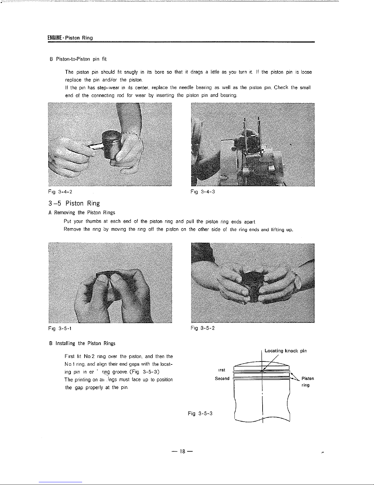
B Piston•to-Piston
The piston pin should fit snugly
replace
If
the pin
end
F,g
3-4-2
3-5
Piston
A
Removing
Put your thumbs at
Remove
pin
the
pin
has
step-wear m
of the connecting rod for wear
Ring
the Piston
the
nng
fit
in
its bore
and/or
the
piston
I1s
center, replace
by
Rings
each
end
of
the
piston ring
by
moving the ring off the piston
so
the
inserting
that it drags a
needle bearing
the
piston
pin
Fig
3-4-3
and
pull
the
on
the other
htt!e
as
as
well
and
bearing
piston ring
side
of
you
turn
as
the
ends
the ring
1t.
piston
apart
ends
If the piston
pm,
Check the
and
lifting
pin
up.
is
loose
small
F,g 3-5-1
B Installing
the
Piston
First
flt
No.2 nng
No
1 ring.
and
align their
ing pin
The printing
in
ec> · ru~'"g
on
the gap properly
Rings
over
the
end
groove.
a11
, lngs must face
at
the pin
piston.
and
gaps with
(Fig.
3-5-3)
up
then
the
to
position
the
locat-
-18-
Fig
Fig
3-5-2
3-5-3
1rst
Second
Locating
/
/
,
knock
~
pin
Piston
ring
C.
Checking the Piston
1)
Measuring piston ring wear ,Put the ring into
the
cylinder so that
cylinder bottom
end
gap with a feeler gauge(Fig
The
end
gap should
mm.
(0.006---0.014")
rings
2)
Removing carbon
Carbon
on
blow -by
Remove the rings
end
of
an
3-6
Piston
The piston
edge.
the
piston rings
old
ring'
is
made
Rings
the
ring
is
and
then
be
between
for
both
No.1
and
from
the piston. and clean the carbon from the rings and
as
a scraper.
of
a high-silicon aluminum
parallel
to
the
measure
·3-5-4)
0.t5
in
the
the
and
0.35
and
No.2
ring grooves will make
alloy.
Fig.
3-5-4
the
rings stick
in
the
piston. thus causing gas
ring
grooves.
ENGINE
-Piston
using
the
A Checking
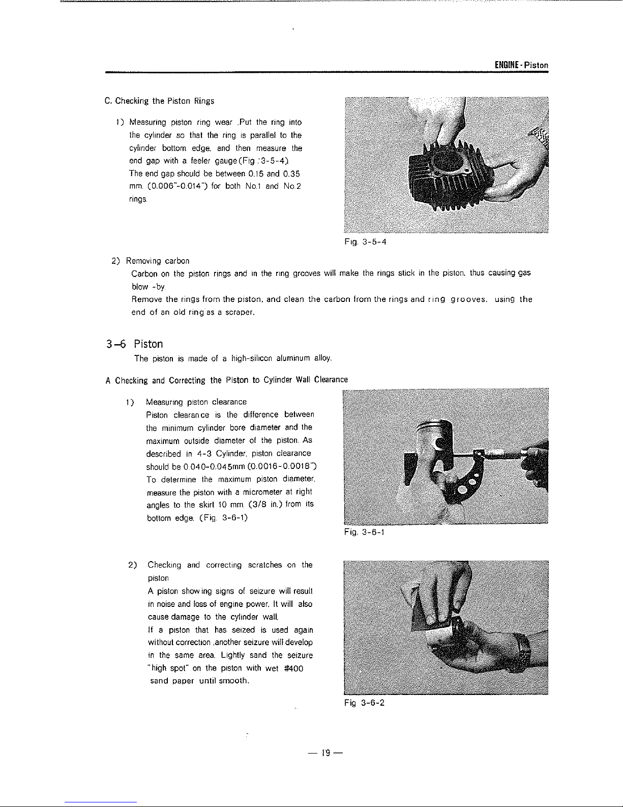
1)
2)
and
Correcting the Piston to Cylinder
Measuring piston clearance
Piston
clearance
the
minimum
maximum
described
should
To determine
measure
angles
bottom
Checking
piston
A piston showing signs
in
cause
If
without correction ,another seizure will develop
in
"high spot"
sand paper
outside diameter
be
0.040-0.04Smm
the
to
the
edge.
noise
and
damage
a piston that
the
same
is
the
difference between
cylinder bore diameter
of
the
in
4-3
Cylinder, piston clearance
(0
0016-0.0018")
the
maximum
piston with a micrometer at right
skirt
10
(Fig
3-6-1)
and
correcting scratches
loss
of engine power. It will also
to
the
has
area.
Lightly sand
on
the piston with wet #400
until
smooth.
piston diameter,
mm.
(3/8
of
seizure will result
cylinder wait
seized
is
Wall
and
the
piston As
in.) from its
on
the
used
again
the
seizure
Clearance
Fig.
3-6-1
-19-
Fig
3-6-2
ENGINE-Piston
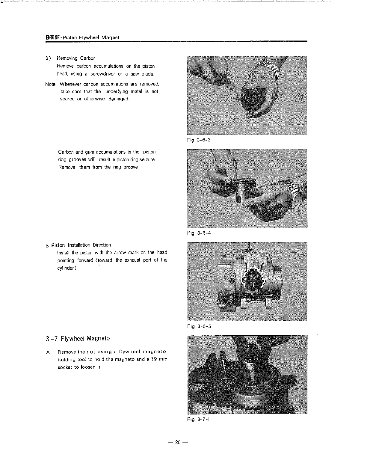
3)
Removing Carbon
Remove carbon
head,
Note Whenever carbon accumlat1ons are removed,
take care that the under lying metal
Flywheel
using a screwdriver or a saw-blade
Magnet
accumulqt1ons
on
the
piston
1s
not
scored or otherwise damaged
F,g
3-6-3
Carbon and
ring grooves will result
Remove them from the ring groove
gum
accumulations
B Piston Installation Direction
Install
the
piston with the arrow mark
pointing forward (toward
cylinder)
in
the
in
piston ring seizure
on
the
exhaust port of
piston
the
head
the
Fig
3-6-4
3
-7
Flywheel Magneto
A Remove the
ho!dmg
socket
tool
to
loosen it.
nut
using a flywheel
to
hold the magneto and a
magneto
19
mm
-20-
Fig
3-6-5
F,g 3-7-1
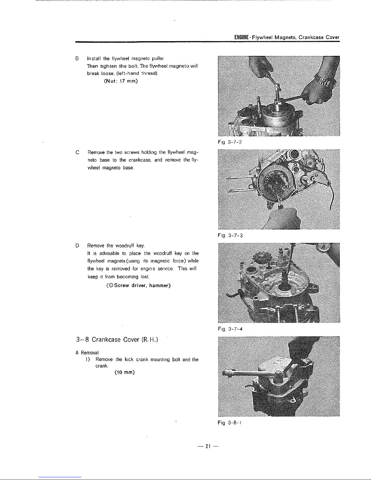
B
In
sta!l
Then
break loose.
C
Remove
neto
wheel magneto
the
flywheel magneto puller
tighten
base
the
bolt.
(left-hand
(Nut:
17
mm)
the
two screws holding
to
the crankcase,
base
The flvvvheel
thread)
the
and
magneto
flywheel mag-
remove
the
will
fly-
Fig
ENGINE·
3-7-2
Flywheel Magneto, Crankcase Cover
D
Remove
It
flywheel magnets (using its magnetic force) while
the
keep it from becoming
3-8
A
Removal
1)
the
woodruff
is
advisable to place
key
is
removed
(0Screw
Crankcase
Remove
crank.
the
(10
key,
the
woodruff key
for
engm
e service
lost
driver, hammer)
Cover
(R.H.)
kick crank mounting bolt
mm)
This
and
on
the
will
the
Fig
Fig
3-7-3
3-7-4
-21-
Fig
3-8-1
ENGINE-Crarkcase Cover,
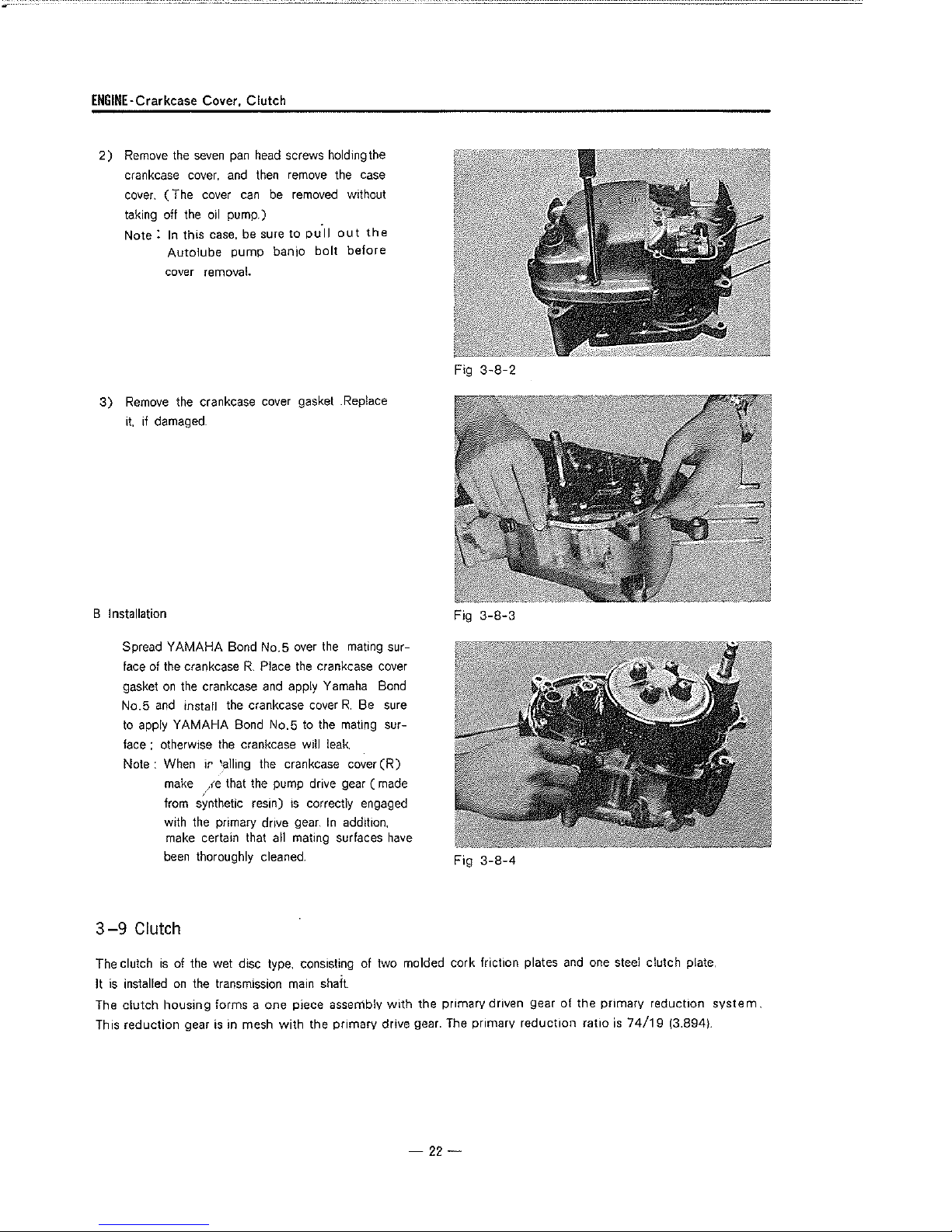
2)
Remove
crankcase
cover.
taking
Note:
the
seven
pan
cover,
and
( The cover
off
the
oil
pump.)
In
this case, be sure
Autolube
pump
cover removal.
3)
Remove
it.
the crankcase cover gasket .Replace
if
damaged.
Clutch
head
screws holding the
then
remove the case
can
be
banjo
removed
to
pull
bolt
without
out
before
the
Fig
3-8-2
B Installation Fig
Spread
YAMAHA
face of
the
gasket
on
the
No.5
and
to
apply
YAMAHA
face : otherwise
Note : When
make ,re that the pump drive gear (
from sYnthetic resin)
with the primary drive
make certain that all mating surfaces
been
3-9
Clutch
The clutch
It
is
The
This reduction gear
installed
clutch
is
of the wet disc type, consisting of two molded cork friction plates
on
housing
Bond
No.5
over
the
crankcase R Place
crankcase
install the crankcase cover
Bond
the
crankcase will leak
ir
'alling the crankcase cover
thoroughly cleaned
the transmission main shaft.
forms a
is
in mesh
the
crankcase cover
and
apply Yamaha Bond
No.5
to
the
1s
correctly engaged
gear_
In
one
piece assembly
with
the primary drive gear. The primary
mating sur-
R.
Be sure
mating
sur-
(R)
made
addition,
have
Fig
with
the primary driven gear
3-8-3
3-8-4
and
of
reduction
one steel clutch plate.
the onmarv reduction
ratio
is
74/19
(3.894).
system.
-22-
ENGINE-Clutch
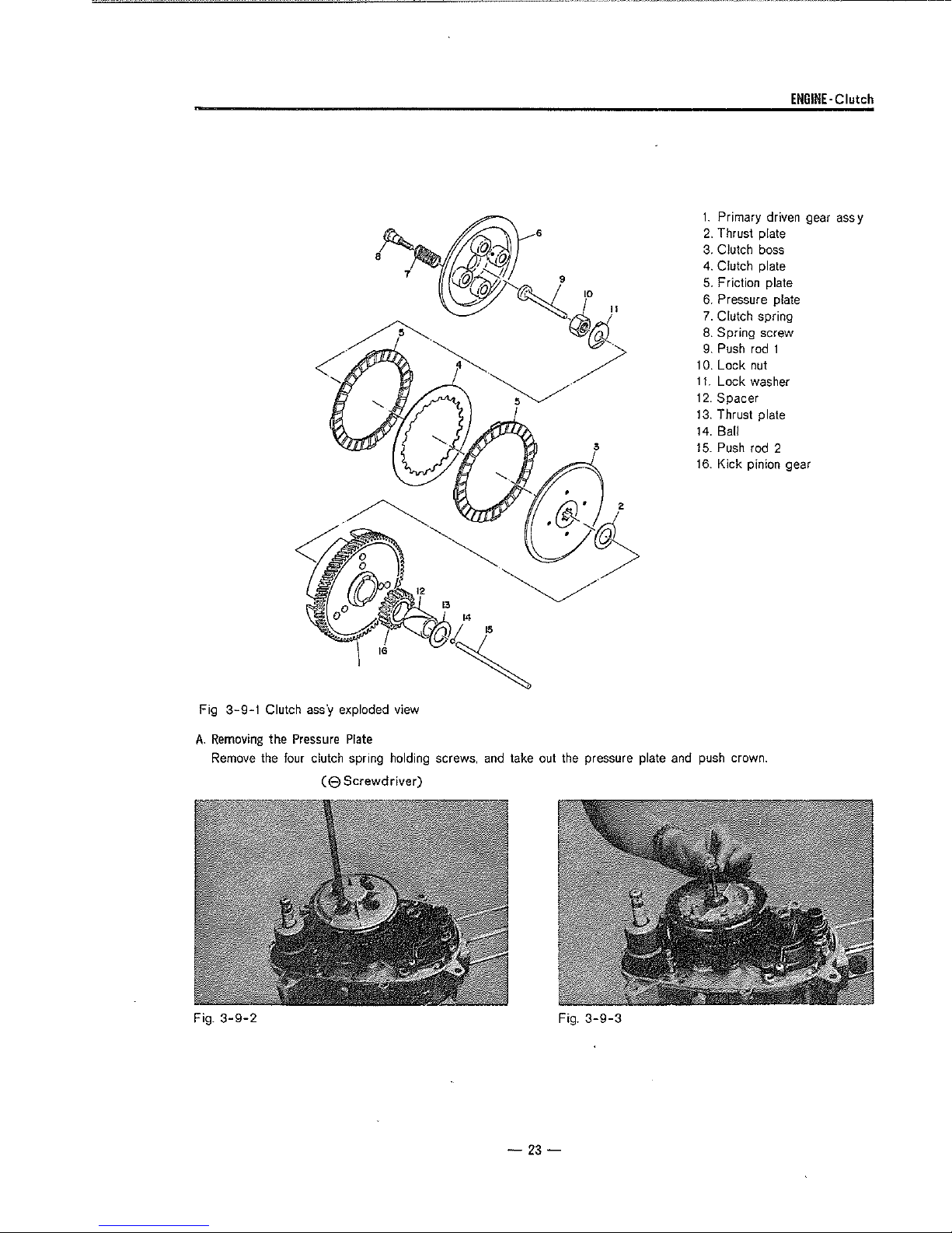
1.
Primary driven gear ass y
2.
Thrust plate
3.
Clutch boss
4. Clutch plate
5.
Friction plate
6.
Pressure plate
7.
Clutch spring
8. Spring screw
9.
Push rod t
10.
Lock
nut
11.
Lock
washer
12.
Spacer
13.
Thrust plate
14.
Ball
15.
Push rod 2
16.
Kick pinion gear
Fig
3-9-1
Clutch
ass'y
exploded view
A.
Removing
Remove the four clutch spring holding screws, and take out the pressure plate and push crown.
Fig.
3-9-2
the
Pressure
( 8
Plate
Screwdriver)
Fig.
3-9-3
-23-

ENGINE·
Clutch
B.
Removing the Clutch Boss
Install the clutch holding tool
Loosen the lock
C.
Checking the Clutch Spring
If
the
free length of the spring is 1
more shorter
nut.
and then remove the clutch
(19
mm)
than
the standard free length, replace
(Slide
calipers)
on
the dutch
mm.
boss.
(0.04
boss.
in.) or
Fig
3-9-4
it.
Free length
D.
Checking the Friction Plates
Measure the fnct1on plate at several
Replace it
or
more. Also replace
evident.
Standard thickness= 3.5 mm. (0.137 in.)
Wear
34
if
(Slide
limit=
3.15
3.5
mm(Standard
it
is
mm.
worn
mm
(1.340
more
11
calipers)
(0.124
Thickness)
m)
than
1f
uneven
in.)
points
for
wear.
0.35mm.(0.0137in.)
contact
1s
quite
(
I
Fig.
Fig.
3-9-5
3-9-6
-
24
--