

Page 1

■
OWNER’S MANUAL
Page 2

MPORTANT SAFETY INSTRUCTIONS
CAUTION
RISK OF ELECTRIC SHOCK
DO NOT OPEN
CAUTION; TO REDUCE THE RISK OF
ELECTRIC SHOCK, DO NOT REMOVE
COVER (OR BACK). NO USER-SERVICEABLE
PARTS INSIDE. REFER SERVICING TO
QUALIFIED SERVICE PERSONNEL
• Explanation of Graphical Symbols
The lightning hash with arrowhead symbol, within an
equilateral triangle, is intended to alert yttit to the
presence of uninsulated "'dangerous voltage" within
the product's enclosure that may be of sulTicient
tnagnitude to constitute a risk of electric shock to
persons.
The exclamation point within an equilateral triangle
is intended to alett yott to the presence of impttrlant
operating and maintenance (servicing) instnictions in
the literatuie accompanying the appliance.
Read Instructions - All the safety and operating inslructions
should he read before the product is operated.
Refaiti histructions - The safety and operating instruclioiis
should be retained for future reference.
Heed Warnings - All warnings on the product and in the
trperating itistruclions should be adhered to.
Follow Inslructions - All operating and use instructions
should be followed.
Cleaning - Unplug this product from the wall outlet before
cleaning. Do not use liquid cleaners or aerosol cleaners. Use
a damp cloth for cleaning.
Attachments - Do not use attachments not recommended by
the product manufacturer as they may cause hazards.
Water and Moisture - Do not use Ihis product near w'ater for example, near a hath tub, wash howl, kilcheii sink, or
laundry tub; in a w'et basement; or near a swnmming pool;
and the like.
Accessories - Do nol place this product on an unstable cart,
stand, tripod, bracket, or table. The product may fall,
causing serious injury to a child or adult, and serious
damage to the product. Use only with a cart, stand, tripod,
bracket, or table recommended by the manufacturer, or sold
with the product. Any mounting of the product should
follow' the manufacturer's instructions, and should use a
mounting accessory recommended by the manufacturer.
A product and cart combination shottld be moved wdth care.
Quick stops, excessive force, and uneven
surfaces may cause the product and cart
combination to overturn.
10 Ventilation - .Slots and openings in the cabinet are provided
for ventilation and to ensure reliable operation of the
product and to protect if from overheating, and these
openings must not be blocked or covered. The openings
should never be blocked by placing the product on a bed,
sofa, rug, or other similar surface. This product shottld nol
he placed in ahuilt-in installation such as a bookcase or rack
unless proper ventilation is provided or the manufacturer’s
instructions have been adhered to.
11 Pow'cr Sources - Tliis product should be operated only from
tile type of pow'er source indicated on the marking label. It
you arc not sure of the type of pow'er supply to your home,
consult your product dealer or local pow'er company. For
products inteiided to operate from hatlery pow'er, or other
sources, refer to the operating instructions.
12 Grounding or Polarization - This product may be equipped
with a polarized alternating current line plug (a plug having
one blade w'idcT than the other). This plug w'ill fit into the
power outlet only one w- ay. This is a satety feature. If you
are unahlc to insert the plug fully into the outlet, fry'
reversing the plug. If the plug should still fail to fit, contact
your electrician to replace your obsolete outlet. Do not
defeat the safety purpose of the polarized plug.
13 Pow'cr-Cord Protection - Pow'er-supply cords should be
routed so that they are not likely lo be walked on or pinched
by items placed upon or against them, paying particular
attcnlion lo cords at plugs, convenience receptacles, and the
point where they exit from the product.
14 Lightning - For added proteclion for this product during a
lightning storm, or when it is left unattended and unused for
long periods of time, unplug it from the w'all oullet and
disconnect the antenna or cable system. This will prevent
damage to the product due to lightning and power-line
surges.
15 Pow'er Lines - An outside antenna system should not be
located in the vicinity of overhead power lines or other
electric light or power circuits, or w.'here it can fall into such
power lines or circuits. When installing an outside antenna
system, extreme care should be taken to keep from touching
such power lines or circuits as contact with them might be
fatal.
16 Overloading - Do not overload wall outlets, extension
cords, or integral convenience receptacles as this can result
in a risk of fire or electric shock.
17 Object and Liquid Entry - Never push objects of any kind
into this product through openings as they may touch
dangerous voltage points or shorl-oul parts that could result
in a fire or electric shock. Never spill liquid of any kind on
Ihe product.
18 Servicing - Do riot attempt to service this product yourself
as opening or removing covers may expose you to
dangerous voltage or other hazards. Refer all servicing to
qualified service personnel.
19 Damage Requiring Service - Unplug this product from the
wall outlet and refer servicing lo qualified service personnel
under llie follow'ing conditions:
a) When the power-supply cord or plug is damaged.
b) If liquid lias been spilled, or objects have fallen into the
product,
c) If the product has been exposed lo rain or w'ater.
Page 3

IMPORTANT SAFETY INSTRUCTIONS
d) If the product does not operate normally by following
the operating instructions. Adjust only those controls
that are covered by the operating instructions as an
improper adjustment of other controls may result in
damage and will often require extensive work by a
qualified technician to restore the product to its normal
operation,
e) If the product has been dropped or damaged in any
way, and
f) When the product exhibits a distinct change in perfor
mance - this indicates a need for service.
20 Replacement Parts - When replacement parts are required,
be sure the service technician has used replacement parts
specified by lire manufacturer or have the same
characteristics as the original part. Unauthorized
substitutions may result in fire, electric shock, or other
hazards.
21 Safety Clieck - Upon completion of any service or repairs to
this product, ask the service technician to perform safety
checks to determine iinit the product is in proper operating
condition,
22 Wall or Ceiling Mounting - Tlie unit should he mounted
to a w'all or ceiling only its recommended hy the
manufacturer.
23 Heat - The product should be situated aw'ay from heat
sources such as radiators, heat registers, stoves, or other
products (including amplifiers) that produce heat.
Note to CATV system installer:
This reminder is provided to call the CATV system installer's
attention to Article 820-40 of the NEC that provides
guidelines for proper grounding and. in particular, specifies
that the cable ground shall be connected to the grounditig
system of the building, as close to the point of ctible entry as
practical.
24 Outdoor Antetma Groundiitg - If an outside antetma or
cable system is connected to the product, be sure the antenna
or cable system is grounded so as to provide some
protection against voltage surges and built-up static charges.
Article 8IOof the National Electrical Code. ANSI/NFPa'tO,
provides information with regard to proper grounding of the
mast and supporting structure, grounding of the lead-in wire
to an antenna discharge unit, size of grounding conductors,
location of antenna discharge tniit, connection to grounding
electrodes, ;ind requirements for the grounding electrode.
EXAMPLE OF ANTENNA GROUNDING
ANTENNA
DISCHARGE UNIT
(NEC SECTION ft10-20)
GROUNDING CONDUCTORS
(NEC SECTION B10-2Î)
GROUND CLAMPS
POWER SERVICE GROUNDING
ELECTRODE SYSTEM
(NEC ART 2S0. PARTH)
FCC INFORMATION (for US customers)
IMPORTANT NOTICE: DO NOT MODIFY THIS
UNIT!
This product, when histalled as hidicated in the
instructions contained in this manual, meets FCC
requirements. Modifications not expressly approved by
Ytimaha may void your authority, granted by the FCC, to
use the product.
IMPORTANT : When connecting this product to
accessories and/or another product use only high quality
shielded cables. Cable/s supplied with Ibis product MU.ST
be used. Follow all installation inslructions. Failure to
follow' instruclions could void your FCC authorization to
use this product, in the USA.
NOTE: This product has been tested and found to comply
with the requirements listed in FCC Regulations, Part 15
for Class "B” digital devices. Compliance w'ith these
rcqtiirernents provides a reasonable level of assurance that
your use of this product in a residential environment w'ill
not result in htiraifnl interference with other electronic
devices.
This equipment geiierates/uses radio frequencies and, if
not installed and used according to the inslructions found
in the users manual, may cause interference harmful to the
operation of other electronic devices.
Compliance with FCC regulations docs not guarantee that
interference will not occur in all installations. If this
product is found to be the source of interference, which
can be determined by turning the unit "OFF" and "ON",
please try to eliminate the problem hy using one of the
following measures:
Relocate either this product or the device that is being
affected hy the interference.
Utilize pow'er outlets that are on different branch (circuit
breaker or fuse) circuits or install AC line filter/s.
In the case of radio or TV interference, relocate/rcoricnt
the antenna. If the antenna lead-in is 300 ohm ribbon lead,
change the lead-in to coaxial type cable.
If these corrective measures do not produce satisfactory
results, please contact the local retailer authorized to
distribute this type of product. If you can not locate the
appropriate retailer, please contact Yamaha Electronics
Corp., U.S.A. 6660 Oraugelhorpe Ave, Buena Park, CA
90620.
The above statements apply ONLY lo those products
distributed hy Yamaha Corporation of America or its
subsidiaries.
Page 4

CAUTION: READ THIS BEFORE OPERATING YOUR UNIT.
1 To assure the finest performance, please read this
manual carefully. Keep it in a safe place for future
reference.
2 Install this sound system in a well ventilated, cool,
dry, clean place - away from direct sunlight, heat
sources, vibration, dust, moisture, and/or cold.
Allow ventilation space of at least 30 cm on the top,
20 cm on the left and right, and 20 cm on the back of
this unit.
3 Locate this unit away from other electrical
appliances, motors, or transformers to avoid
humming sounds.
4 Do not expose this unit to sudden temperature
changes from cold to hot, and do not locate this unit
in a environment with high humidity {i.e. a room with
a humidifier) to prevent condensation inside this
unit, which may cause an electrical shock, fire,
damage to this unit, and/or personal injury.
5 Avoid installing this unit where foreign object may
fall onto this unit and/or this unit may be exposed to
liquid dripping or splashing. On the top of this unit,
do not place:
- Other components, as they may cause damage
and/or discoloration on the surface of this unit.
- Burning objects (i.e. candles), as they may cause
fire, damage to this unit, and/or personal injury.
- Containers with liquid in them, as they may tall
and liquid may cause electrical shock to the user
and/or damage to this unit.
6 Do not cover this unit with a newspaper, tablecloth,
curtain, etc. in order not to obstruct heat radiation. If
the temperature inside this unit rises, it may cause
fire, damage to this unit, and/or personal injury.
7 Do not plug In this unit to a wall outlet until all
connections are complete.
8 Do not operate this unit upside-down. It may
overheat, possibly causing damage.
9 Do not use force on switches, knobs and/or cords.
10 When disconnecting the power cord from the wall
outlet, grasp the plug; do not pull the cord.
11 Do not clean this unit with chemical solvents; this
might damage the finish. Use a clean, dry cloth.
12 Only voltage specified on this unit must be used.
Using this unit with a higher voltage than specified
is dangerous and may cause fire, damage to this
unit, and/or personal injury. YAMAHA will not be
held responsible for any damage resulting from use
of this unit with a voltage other than specified.
13 To prevent damage by lightning, disconnect the
power cord and outdoor antenna from the wall outlet
during an electrical storm.
14 Do not attempt to modify or fix this unit. Contact
qualified YAMAHA service personnel when any
service is needed. The cabinet should never be
opened for any reasons.
15 When not planning to use this unit for long periods
of time (i.e. vacation), disconnect the AC power plug
from the wall outlet.
16 Be sure to read the “TROUBLESHOOTING” section
on common operating errors before concluding that
this unit is faulty.
17 Before moving this unit, press STANDBY/ON to set
this unit in the standby mode, and disconnect the
AC power plug from the wall outlet.
WARNING
TO REDUCE THE RISK OF FIRE OR ELECTRIC
SHOCK, DO NOT EXPOSE THIS UNIT TO RAIN
OR MOISTURE.
This unit is not disconnected from the AC power
source as long as it is connected to the wall outlet, even
if this unit itself is turned off. This .state is called the
standby mode. In this state, this unit is designed to
consume a very small quantity of power.
FOR CANADIAN CUSTOMERS
To prevent electric shock, match wide blade of plug to
wide slot and fully insert.
This Class B digital apparatus complies with Canadian
ICES-003.
IMPORTANT
Please record the serial number of this unit in the space
below.
MODEL:
Serial No.:
The .serial number is located on the rear of the unit.
Retain this Owmer’s Manual in a safe place for future
reference.
We Want You Listening For A Lifetime
YAMAHA and Ihe Electronic Industries Association’s Consumer
Electronics Group want you to get the most out of your equipment
by playing it at a safe level. One that lets the sound come through
loud and clear without annoying blaring or distortion - and, most
importantly, without affecting your sensitive hearing.
Ill
Since hearing damage from loud sounds is often
undetectable until it is too late, YAMAHA and the
Electronic Industries Association's Consumer
Electronics Group recommend you to avoid
prolonged exposure from excessive volume levels.
Page 5

CONTENTS
ODUCTION
I l ATURES..........................................................................2
GETTING STARTED..........................................................3
Supplied accessories
Installing batteries in Ihe remote control
CONTROLS AND FUNCTIONS
Front panel
Remote control.........................................................6
Using the remote control..........................................7
Front panel display...................................................8
Rear panel................................................................10
SPEAKER SETUP..............................................................11
Speaker placement................................................ 11
Speaker connections...............................................12
CONNECTIONS................................................................15
Before connecting componenls..............................13
Connecting video components
Connecting audio components
Connecting the FM and AM antennas
Connecting the power supply cord.........................22
Speaker impedance setting.....................................22
Turning on the power.............................................23
AUTO SETUP
...................................................................
Introduction............................................................24
Optimizer microphone setup
Starting the setup
PI AYBACK
.......................................................................
Basic operations
Selecting sound field programs..............................32
Selecting input modes
FM/AM TUNING
Automatic and manual tuning
Presetting stations
Selecting preset stations
Exchanging preset stations.....................................42
XM Satellite Radio TUNING............................................44
What is XM Satellite Radio?..................................44
XM Satellite Radio connections.............................44
XM Satellite Radio functions.................................45
Activating XM Satelliie Radio...............................46
Basic XM Satellite Radio operations
XM Satellite Radio search modes
Setting XM Satellite Radio preset channels
RECORDING....................................................................54
................................................
.................
........................................
...............................................................
...............................
...............................
...................
..................................
...................................................
.....................................................
............................................
.............................................................
................................
..................................................
........................................
.....................
..........................
..........
16
19
21
24
24
25
3»
30
36
38
38
39
41
47
48
51
SOUND FIELD PROGRA
SOUND FIELD PROGRAM DESCRIPTIONS 55
For rnovieA'idco sources
3
For music sources
3
4
4
ADVANCED OPERATIONS.............................................58
Selecting the OSD mode........................................58
Using the sleep iimer
Manually adjusting speaker levels
SET MENU................1
Using SET MENU
1 SOUND MENU
2 INPUT MENU....................................................68
3 OPTION MENU
ADVANCED SETUP MENU
REMOTE CONTROE FEATURES...................................74
Control area............................................................74
Setting remote control codes..................................73
Controlling other components
Sw'itching library codes.........................................77
Clearing set up remote control codes
EDITING SOUND FIELD PARAMETERS
What is a sound field..............................................78
Changing parameter settings
SOUND FIELD PARAMETER
DESCRIPTIONS..........................................................80
TROUBLESHOOTING.....................................................85
RESETTING THE FACTORY PRESETS
GLOSSARY
.......................................................................
Audio formats........................................................91
Sound field programs.............................................92
Audio information..................................................92
Video signal information
SPECIFICATIONS............................................................94
.......................................
..................................................
.............................................
.........................
.....................................................
.................................................
..................................................
.................................................
............................................
................................
.....................
.......................
..................................
..........................
.......................................
55
57
58
59
60
62
63
70
72
76
77
78
78
90
91
93
Page 6

FEATURES
Built-In 7-channel power amplifier
♦ Minitmim RMS output power
(0,06% THD, 20 Hz to 20 kHz, 8 Q)
Front: 95 W + 95 W
Center: 95 W
Surround: 95 W + 95 W
Surround back: 95 W + 95 W
Sound field features
♦ Proprietary YAMAHA technology for the creation of
sound fields
♦ Dolby Digital/Dolby Digital EX decoder
♦ DTS/DTS-ES Matrix 6.1, Discrete 6.1, DTS Neo:6,
DTS 96/24 decoder
♦ Dolby Pro Logic/Dolby Pro Logic II/
Dolby Pro Logic IIx decoder
♦ Virtual CINEMA DSP
♦ SILENT CINEMA"’
Sophisticated AM/FM tuner
♦ 40-station random and direct preset tuning
♦ Automatic preset tuning
♦ Preset station shifting capability (preset editing)
XM Satellite Radio
♦ XM Satellite Radio programming (using the “XM
Connect and Play digital antenna accessory”, sold
separately)
Other features
♦ YPAO: YAMAHA Parametric Room Acoustic
Optimizer for automatic speaker setup
♦ 192-kHz/24-bit D/A converter
♦ A SET MENU that provides you with items for
optimizing this unit for your audio/video system
♦ 8 additional input jacks for discrete multi-channel input
♦ PURE DIRECT for pure fidelity sound with analog and
PCM sources
♦ On-screen display function helpful in controlling this
unit
♦ S-video signal input/output capability
♦ Component video input/output capability
♦ Video signal conversion (Composite video S-video
—> Component video) capability for monitor out
♦ Optical and coaxial digital audio signal jacks
♦ Sleep timer
♦ Cinema and music night listening modes
♦ Remote control with preset remote control codes
' -T- indicates a tip for your operation.
' Some operations can be performed by using either the buttons on the main unit or on the remote control. In cases when the button
names differ between the main unit and the remote control, the button name on the remote control is given in parentheses.
■ This manual is printed prior to production. Design and specifications are subject to change in part as a result of improvements, etc. In
case of differences between the manual and product, the product has priority.
miDOLlYl
Matiufttctured under license from Dolby Laboratories.
“Dolby”, “Pro Logic”, “Surround EX”, ttnd the double-D symbol
are trademarks of Dolby Laboratories.
SILENT “
CINEMA
"SILENT CINEMA” is a trademark of YAMAHA
CORPORATION.
“DTS”, “DTS-ES”, “Nco:6” and “DTS 96/24" arc trademarks of
Digital Theater Systems, Inc,
XM
The XM name and rekued logos are registered trademttrks of XM
Satellite Radio Inc.
Page 7

GETTING STARTED
Supplied accessories
Please check that you received all of the following parts.
Remote control Batteries (4)
03 C3
Ò O O 3
o o o o"
o U 5 H
□ D E3
O © 0 0
_ ™
0-0 0 0
©
gg s s s
S S G3 EO
(AAA, R03, UM-4)
Indoor FM antenna
AM loop antenna
Optimizer microphone
installing batteries in the remote
control
1 Press the 'W part and slide the battery
compartment cover off.
2 Insert four supplied batteries (AAA, R03,
UIVI-4) according to the polarity markings
(+ / -) on the inside of the battery
compartment.
Notes on batteries
• Change all of the batteries if you notice the following
conditions; the operation range of the remote control decrciises.
the indicator docs not flash or its light becomes dim.
• Do not use old batteries together wdth new ones.
• Do not use different types of batleries (such as alkaline and
manganese batleries) together. Read the packaging carefully as
these different types of batteries may have the same shape anti
color.
• If the batteries have leaked, dispose of them immediately. Avoid
touching the leaked material or letting it come into contact with
clothing, etc. Clean the battery compartment thoroughly before
installing new batteries.
• Do not throw away batteries with general house waste; dispose
of them correctly in accordance with vonr local regulations.
If the remote control is without batteries for more than
2 minutes, or if exhausted batteries remain in the
remote control, the contents of the memory may be
cleared. When the memory is cleared, insert newbatteries, set up the remote control code and program
any accjuired functions that may have been cleared.
3 Slide the cover back until it snaps into place.
Page 8

Front panel
CONTROLS AND FUNCTIONS
O STANDBY/ON
Turns on this unit or sets it to the standby mode. When you
turn on this unit, you will hear a click and there will be a 4
to 5-second delay before this unit can reproduce sound.
Note
In standby mode, this unit consumes a small amount of power in
order to receive infrared-signals from the remote control.
o PURE DIRECT
Turns on or off PURE DIRECT mode (see page 34).
0 Remote control sensor
Receives signals from the remote control.
O Front panel display
Shows information about the operational status of this
unit.
0 PRESET/TUNING (EDIT), SEARCH MODE
Switches the function of PRESET/TUNING/CH <1 / >
(LEVEL -!+) between selecting preset station numbers
and tuning.
0 FM/AM,XM*
Switches the reception band when the unit is in tuner
mode.
0 A/B/C/D/E, NEXT, CATEGORY*
Selects one of the 5 preset station groups (A to E) when
the unit is in tuner mode.
Selects the speaker channel to be adjusted when the unit is
not in tuner mode.
0 PRESET/TUNING/CH <] />, LEVEL-/+
Selects preset station number 1 to 8 when the colon (:) is
displayed next to the band indication in the front panel
display when the unit is in tuner mode. Selects the tuning
frequency when the colon (:) is not displayed.
Adjusts the level of the speaker channel selected using
A/B/C/D/E (NEXT) w,hen the unit is not in tuner mode.
0 MEMORY (MAN’L/AUTO FM)
Stores a station in the memory. Hold down this button for
more than 3 seconds to start automatic preset tuning.
0 TUNING MODE (AUTO/MAN’L MONO),
DISPLAY*
Switches the tuning mode between automatic (AUTO
indicator on) and manual (AUTO indicator off).
0 VOLUME
Controls the output level of all audio channels.
This does not affect the REC OUT level.
Page 9

® OPTIMIZER MIC jack
Use to connect and input audio signals from the supplied
microphone for use with the AUTO SETUP function (see
page 24).
© n PHONES (SILENT CINEMA) jack
Outputs audio signals for private listening with
headphones. When you connect headphones, no signals
are output to the PRE OUT jacks or to the speakers.
All Dolby Digital and DTS audio signals are mixed down
to the left and right headphone channels.
© SPEAKERS A/B
Turns on or off the set of front speakers connected to the A
and/or B terminals on the rear panel each time the
corresponding button is pressed.
© STRAIGHT (EFFECT)
Switches the sound fields off or on. When STRAIGHT is
selected, input signals (2-channel or multi-channel) are
output directly from their respective speakers without
effect processing.
© PROGRAM
Use to select sound field programs or adjust the bas.s/treble
balance (in conjunction with TONE CONTROL).
CONTROLS AND FUNCTIONS
© TONE CONTROL
Use to adjust the bass/treble balance for the front left and
right, center, presence and subwoofer channels (see
pages 31).
© INPUT MODE
Sets the priority (AUTO, DTS, ANALOG) for the type of
signals received w'hen one component is connected to two
or more of this unit’s input jacks (see page 36).
© INPUT selector
Selects the input source you want to listen to or watch.
@ MULTI CH INPUT
Selects the source connected to the MULTI CH INPUT
jacks. When selected, the MULTI CH INPUT source takes
priority over the source selected with INPUT (or the input
selector buttons on the remote control).
© VIDEO AUX jacks
Input audio and video signals from a portable external
source such as a game console. To reproduce source
signals from these jacks, select V-AUX as the input
source.
Available only when the unil is in the XM Satellile Radio
mode (see page 43).
Page 10

CONTROLS AND FUNCTIONS
Remote control
This section describes the function of each control on the
remote control used to control this unit. To operate other
components, see '‘REMOTE CONTROL FEATURES” on
page 74.
m
CftBE SET TiANSJliT S
#
m
#
m
T) r _ _
~ ^ I SVSTEfi
POWER POWER STAUD&Yi} POWER
TV H ji: AV |il !!■ d) j
5 CD MDfCD-R TUNER« SLEEP
o o o c
5 DVD DTV/CBL V-AUX ? MULTI CH IK
o o o o
DVRV'"R2 I Afilp
O Q O
I + 1 +
TV VOL TV C 71
TV rdUlE TU IMP
□ c
O © 0 ©i
>.fAriDARU ’»eLe. T EXTD SUP rUfibHIHbi
(^T'( (fc 1 (Tj
■■
...............
I " ! f '! I I
miic smi'
UT
]
A ^EAkfcftS B 5 NIGHT f STRAIGHT
- [rFi-Ti:!
fhE Lfc-K
IfVN C.
t©J i
BiMD is
: ENTER
[{-(El
A-EXAT. b:
MEhOK/ ^
[TTJ r 1
-
■ 1
j 1
1 (TToj ( Eli! j
V
+ r
i'f'LULiE I
-V? SETMEfiU
1 1 UENu]
i|i SRCKMODi
A El AT
: ? 1 QjSI>LflY 1
}f iREEf
®
m
m
m
O Infrared window
Outputs infrared control signals. Aim this window at the
component you want to operate.
0 CODE SET
Use to set up remote control codes (see page 73).
0 Input selector buttons
Select the input source and change the control area.
O Sound field program/numeric buttons
Use to select sound field programs.
Use numbers 1 through 8 to select preset stations when the
unit is in tuner mode.
Use SELECT to playback 2-channel sources in multiple
channel format (see page 33).
Use EXTD SUR. to switch between 5.1 or 6.1/7.1-channel
playback of multi-channel software (see page 33).
Use PURE DIRECT to turn on or off PURE DIRECT
mode (see page 34).
0 SPEAKERS A/B
Use to turn on or off the set of front speakers connected to
the A and/or B terminal on the rear panel each time the
corresponding button is pressed.
0 LEVEL, BAND
Selects the speaker channel to be adjusted and sets the
level.
Switches the reception band when the unit is in tuner
mode.
0 Cursor buttons y\l\/ / < / > /ENTER
Use to select and adjust sound field program parameters or
SET MENU items.
Press "C / )> to select a preset station group (A to E) when
the unit is in tuner mode.
Press /o, / V" to select a preset station number (1 to 8)
when the unit is in tuner mode.
0 RETURN, MEMORY*
Returns to the previous menu level when adjusting the
SET MENU parameters.
imiflHA
0 TRANSMIT indicator
Flashes while the remote control is sending signals,
0 STANDBY
Sets this unit in the standby mode.
0 SYSTEM POWER
Turns on the power of this unit.
Page 11

® SLEEP
Sets the sleep timer.
® MULTI CH IN
Selects multi-channel input when using an external
decoder (etc.).
0 AMP
Selects the AMP mode. You must select the AMP mode to
control the main unit.
© VOLUME +/-
Increases or decreases the volume level.
© MUTE
Mutes the sound. Press again to restore the audio output to
the previous volume level.
© NIGHT
Turns on or off the night li.stening modes (.see page 35).
© STRAIGHT (EFFECT), ENT*
Switches the sound fields off or on. When STRAIGHT is
selected, input signals (2-channel or multi-channel) are
output directly from their respective speakers without
effect processing.
© SET MENU, SRCH MODE*
Activates the SET MENU function.
* Available only when the unit is in the XM Salcllile Radio
mode (see page 45 ).
CONTROLS AND FUNCTIONS
Using the remote control
The remote control transmits a directional infrared beam.
Be sure to aim the remote control directly at the remote
control sensor on the main unit during operation.
Handling the remote control
Do not spill water or other liquids on the remote
control.
Do not drop the remote control.
Do not leave or store the remote control in the
following types of conditions:
- places of high humidity, such a.s near a bath
~ high temperature, such as near a heater or stove
- extremely low temperatures
- dusty places
Page 12

CONTROLS AND FUNCTIONS
Front panel display
# # # # #
MATRIX DISCRETE
[ □□ DIGITALI
fm Exìl'an pl'
¡□D PLlllDD PLlx
i PCM Ï ' '
©
m m em ] ' VC R1 y ' V-A UX
VIR TUA L' SIL EMT CIM EMA ^
STA HDA RD
i ? □□□□□
5 □□□□□
1 5 □□□□ □
■ gææ ((((( ggg guss sss s ssss
■ sæ æ aaaa a
MK HT « 'A Bf
uuu uu
UU UUU .I: UUUUU UU UUU
llllllllll
llllllllll 'S lllll lllll lllllll lll
nrin rin
nrin rin n rinrin nrinrin
m
|SP 1 , ■
DTV/CBL DVD ID/CD-R TUNER . CD PHONO
O Decoder indicators
When any of this unit’s decoders function, the respective
indicator lights up.
Q ViRTUAL indicator
Lights up when Virtual CINEMA DSP is active (see
page 35).
@ SiLENT CiNEMA Indicator
Lights up when headphones are connected and a sound
field program is selected (see page 31).
O Input source indicators
A cursor lights to show the current input source.
0 Sound field indicators
Light to indicate the active DSP sound fields.
Presence DSP sound field
Listening position
Left surimmd
DSP sound held
Surround back DSP sound field
0 CINEMA DSP indicator
Lights up when you select a CINEMA DSP sound field
program.
O YPAO indicator
Lights up during the auto setup procedure and when the
auto setup speaker settings are used without any
modifications.
0 AUTO indicator
Lights up when this unit is in automatic tuning mode.
0 TUNED indicator
Lights up when this unit is tuned into a station.
Right surround
[).SP sound field
# ®
YPAO AUTO TUMEDSTEREO 'MEMORY MUTE VOLUME
HiFi DSP
SLEEP
....
SB di LFE
© @
0 STEREO indicator
Lights up when this unit is receiving a strong signal for an
LM stereo broadcast while the AUTO indicator is lit.
0 MEMORY indicator
Llashes to show that a station can be stored.
0 MUTE indicator
Llashes while the MUTE function is on.
0 VOLUME level indication
Indicates the current volume level.
0 PCM indicator
Lights up when this unit i.s reproducing PCM (Pulse Code
Modulation) digital audio signals.
© STANDARD
Lights up when Surround Standard or Surround Enhanced
is selected (see page 33).
0 NIGHT indicator
Lights up when you select night listening mode.
0 SP A B indicators
Light up according to the set of front speakers selected.
Both indicators light up when both sets of speakers are
selected.
0 Headphones indicator
Lights up when headphones are connected.
0 HiFi DSP indicator
Lights up when you select a HiFi DSP sound field
program.
0 Multi-information display
Shows the current sound field program name and other
information when adjusting or changing settings.
8
Page 13

@ SLEEP indicator
Lights up while the sleep timer is on.
@ 96/24 indicator
Lights up when a DTS 96/24 signal is input to this unit,
@ LFE indicator
Lights up when the input signal contains the LFE signal.
@ input channei indicators
Indicate the channel components of the current digital
input signal.
CONTROLS AND FUNCTIONS
Page 14
CONTROLS AND FUNCTIONS
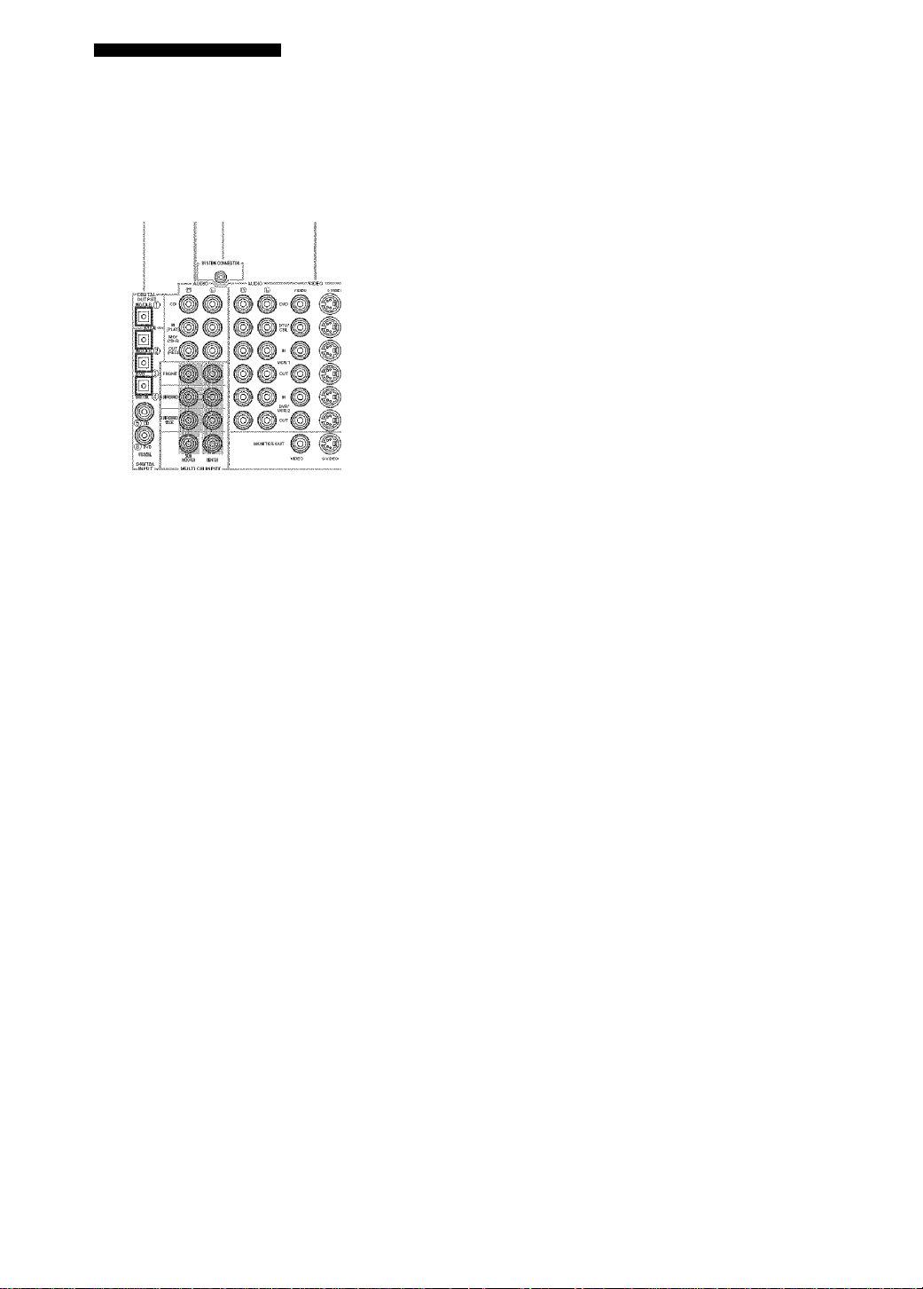
Rear panel
? ?
©
T r T
"'B®®
r®'® ®
Hi
i
o DIGITAL OUTPUT jack
See page 19 for details.
0 Audio component jacks
See page 19 for connection information.
0 SYSTEM CONNECTOR jack
Use to connect a YAMAHA subwoofer equipped with a
SYSTEM CONNECTOR jack to this unit (see page 13).
O Video component jacks
See pages 16 and 18 for connection information.
0 Antenna terminals
See page 21 for connection information.
iMH
liOUrLETS
(U.S.A. model)
i
0 ACOUTLET(S)
Use to supply power to your other A/V components {see
page 22).
0 DIGITAL INPUT jacks
See pages 16, 18 and 19 for details.
0 MULTI CH INPUT jacks
See page 17 for connection information.
0 PRE OUT jacks
See page 20 for connection information.
0 Speaker terminals
See page 13 for connection information.
0 PRESENCE speaker terminals
See page 13 for connection information.
0 XM jack
See page 44 for connection information.
10
Page 15

SPEAKER SETUP
Speaker placement
The speaker layout below shows the standard ITU-R’“
speaker setting. You can use it to enjoy CINEMA DSP and
multi-channel audio sources.
* ITU-R is the radio communication sector of the ITU
(Interniitioiial Telecommunication Union).
Surround speakers (SR and SL)
The surround speakers are used for effect and surround
sounds. Place these speakers behind your listening
position, facing slightly inwards, about 1.8 ni (6 ft) above
the floor.
Surround back speakers (SBR and SBL)
The surround back speakers supplement the surround
speakers and provide for more realistic front-to-back
transitions. Place these speakers directly behind the
listening position and at the same height as the surround
speakers. They should be positioned at least 30 cm (12 in)
apart. Ideally, they should be positioned at the same width
as the front speakers.
Subwoofer
The use of a subwoofer, such as the YAMAPIA Active
Servo Processing Subwoofer System, is effective not only
for reinforcing bass frecjnencies from any or all channels,
but also for high fidelity reproduction of the LEE (lowfrec[uency effect) channel included in Dolby Digital and
DTS software. The position of the subwoofer is not so
critical, because low bass sounds are not highly
directional. But it is better to place the subwoofer near the
front speakers. Turn it slightly toward the center of the
room to reduce wall reflections.
Front speakers (FR and FL)
The front speakers are used for the main source sound plus
effect sounds. Place these speakers an equal distance from
the ideal listening position. The distance of each speaker
from each side of the video monitor should be the same.
Center speaker (C)
The center speaker is for the center channel sounds
(dialog, vocals, etc.). If for some reason it is not practical
to use a center speaker, you can do without it. Best results,
however, are obtained with the full system. Align the front
face of the center speaker with the front face of your video
monitor. Place the speaker centrally between the front
speakers and as close to the monitor as possible, such as
directly over or under it.
Presence speakers (PR and PL)
Presence speakers supplement the sound from the front
speakers with extra ambient effects produced by CINEMA
DSP (see page 55). These effects include sounds that
filmmakers intend to locate a little farther back behind the
screen in order to create more theater-like ambience. Place
these speakers at the front of the room about 0.5 - 1 m
ft) outside the front speakers, facing slightly
(1-3
inwards, and about 1.8 m (6 ft) above the floor.
11
Page 16

SPEAKER SETUP
Speaker connections
Be sure to connect the left channel (L), right channel (R),
(red) and ‘(black) properly. If the connections are
faulty, no sound will be heard from the speakers, and if the
polarity of the speaker eonnections is incorrect, the sound
will be unnatural and lack bass.
CAUTION
• If you will use 4 or 6 ohm speakers, be sure to
set this unit’s speaker impedance setting to
4 ohms before using (see page 22).
• Before connecting the speakers, make sure that the
power of this unit is off.
• Do not let the bare speaker w ires touch each other or do
not let them touch any metal part of this unit. This
could damage this unit and/or speakers.
• Use magnetically shielded speakers. If this type of
speakers still creates the interference with the monitor,
place the speakers away from the monitor.
A speaker cord is actually a pair of insulated cables
running side by side. One cable is colored or shaped
differently, perhaps with a stripe, groove or ridges.
Connect the striped (grooved, etc.) cable to the “+” (red)
terminals on this unit and your speaker. Connect the plain
cable to the (black) terminals.
10 mm (3/8")
5 Tighten the knob to secure the wire.
Black: negative (-)
Connecting to PRESENCE speaker terminals
1 Open the tab.
2 Insert one bare wire into the hoie of each
terminal.
1 Remove approximately 10 mm (3/8") of
insulation from the end of each speaker
cable.
2 Twist the exposed wires of the cable together
to prevent short circuits.
3 Unscrew the knob.
4 Insert one bare wire into the hole in the side
of each terminal.
3 Return the tab to secure the wire.
■ Banana plug connections
First, tighten the knob and then insert the banana plug
connector into the end of the corresponding terminal.
You can also use banana plugs with the PRESENCE speaker
terminals. Open the tab, then insert one banana plug connector
itito the hole of each terminal. Do not attempt to close the tabs
after connecting the banana plugs.
12
Page 17

SPEAKER SETUP
Front speakers (A)
You сап connect both surround back and presence speakers to this unit, but they do not output sound sirnuitaneously.
• The surround back speakers output the surround hack channel included in Dolby Digital EX and DTS-ES software and only
operate w'hen the Dolby Digital EX, DTS-ES or Dolby Pro Logic IIx. decoder is turned on.
• The presence speakers output ambient effects created by the DSP sountl fields. They do not output sound when other sound fields
are selected-
13
Page 18

SPEAKER SETUP
■ FRONT terminals
Connect one or two speaker systems (6, 7) to these
terminals. If you use only one speaker system, connect it
to the FRONT A or B terminals.
■ CENTER terminals
Connect a center speaker (8) to these terminals.
■ SURROUND terminals
Connect surround speakers (4, 5) to these terminals.
■ SURROUND BACK terminals
Connect surround back speakers (9, 10) to these terminals.
If you only connect one surround back speaker, connect it
to the left (L) terminals.
■ PRESENCE terminals
Connect presence speakers (2, 3) to these terminals.
■ SUBWOOFER PRE OUT jack
Connect a subwoofer with built-in amplifier (1), such as
the YAMAHA Active Servo Processing Subwoofer
System, to this jack.
■ SYSTEM CONNECTOR jack
U.se this jack to control the power of your YAMAHA
subwoofer if a system connector jack is available on the
subw-'oofer.
'Am
0
10.
Speaker layout
14
Page 19

CONNECTIONS
Before connecting components
CAUTION
Do not connect this unit or other components to the mains
power until all connections between components are
complete.
■ Cable indications
For analog signals
left analog cables
righl analog cables
For digital signals
optical cables
coaxial cables
For video signals
video cables
S-video cables
-:lf L'p-
«fo].
Dust protection cap
Pull out the cap from the optical jack before you connect
the fiber optic cable. Do not discard the cap. When you are
not using the optical jack, be sure to put the cap back in
place. This cap protects the jack from dust.
■ Video jacks
This unit has three types of video jacks. Connection
depends on the availability of input jacks on your monitor.
The signals input through the S VIDEO jacks on this unit
are automatically converted for output through the VIDEO
jacks. When VIDEO CONV. is set to ON (see page 70),
signals input through the VIDEO jacks can be output
through the S VIDEO and COMPONENT VIDEO jacks.
Likewise, signals input through the S VIDEO jacks can
also be output through the COMPONENT VIDEO jacks.
VIDEO
COMPONENTViDEO
componenl video cables
4-j^l
L.171 .
■ Analog jacks
You can input analog signals from audio components by
connecting audio pin cable to the analog jacks on this unit.
Connect red plugs to the right jacks and white plugs to the
left jacks.
■ Digital jacks
This unit has digital jacks for direct transmission of digital
signals through either coaxial or fiberoptic cables. You
can use the digital jacks to input PCM, Dolby Digital and
DTS bitstreams. When you connect components to both
the COAXIAL and OPTICAL jacks, priority is given to
the input signals from the COAXIAL jack. All digital
input jacks are compatible with 96-kHz sampling digital
signals.
Note
This unit handles digital and analog signals independently. Thus
audio signals input to Ihe analog jacks are only oulput lo the
analog OUT (REC) jacks. Likewise audio signals input lo the
digital (OPTICAL or COAXIAL) jacks are only output to the
DIGITAL OUTPUT jack.
VIDEO jacks
For conventional composite video signals.
S VIDEO jacks
For S-Video signals, separated into luminance (Y) and
color (C) video signals to achieve high-quality color
reproduction.
COMPONENT VIDEO jacks
For component signals, separated into luminance (Y) and
color difference (Pb, Pr) to provide the best quality in
picture reproduction.
Signal flow inside this unit
Input
COMPONENT
VÌDEO
©
Only when VIDEO CONV. is set to ON
(see page 70).
Output
(MONITOR OUT)
©
Note
When signals are input through both the S VIDEO and VIDEO
jacks, signals input through the ,S VIDEO jack have priority.
15
Page 20

CONNECTIONS
Connecting video components
■ Connections for DVD playback
Note
Be sure to connect your video source components in the same way you connect your video monitor to this unit if V.CONV (see page 70)
is set to OFF- For example, if you conned your video monitor to this unit using a VIDEO connection, connect your video source
components to this unit using the VIDEO connections. (Even when V.CONV is set to OFF, S-video signals input from your video
scHirce component are automatically converted to composite signals in this unit.)
16
Page 21

CONNECTIONS
■ Connecting to the MULTI CH INPUT jacks
This unit is equipped with 8 additional input jacks (left and right FRONT, CENTER, left and right SURROUND, left and
right SURROUND BACK and SUBWOOFER) for discrete multi-channel input from a multi-format player, external
decoder, sound processor or pre-amplifier.
Connect the output jacks on your multi-format player or external decoder to the MULTI CH INPUT jacks. Be sure to
match the left and right outputs to the left and right input jacks for the front and surround channels.
For 6-channel input For 8-channel input
I
e'i
ill
‘"m "
......
WDOFES CENfER
; .MDI..;: .i: lid ■): c
i
jiif-if.: 'i
Si.i.i.i.i.i.i.iji-r
f"l
Notes
• When you select MULTI CH INPUT as the input source, this unit automatically turns off the digital sound field processor, and you
cannot select sound field programs.
• This unit does not redirect signals input to the MULTI CH INPUT jacks to accommodate for missing speakers. We recommend that
you connect at least a 5.1-channel speaker system before using this feature.
• When headphones are used, only front left and right channels tire output.
t A
17
Page 22

CONNECTIONS
■ Connections for other video components
Notes
• Be sure to connect your video scaircc components in the same way you connect your video monitor 1(5 this unit if VIDEO CONV. (see
page 70) is set to OFF. For example, if you connect your video rnonilor to this unit using a VIDEO connection, conned your video
scmrce ccnnponents to this unit using the VIDEO connections. (Even when V.CONV is set to OFF, S-video signals input from your
video source component are aulomatically converted to composite signals in this unit.)
• Converted video signals are only output to the MONITOR OUT Jacks. When recording you must make the same type of video
connections (i.e., S-video) belw'een each ccnnponent.
■ VIDEO AUX jacks {on the front panel)
Use these jacks to connect any video source, such as a
same console or video camera, to this unit.
18
Page 23

Connecting audio components
I Connections for audio components
CONNECTIONS
19
Page 24

CONNECTIONS
■ Connecting to an external amplifier
If you want to increase the power output to the speakers,
or want to use another amplifier, connect an external
amplifier to the PRE OUT jacks as follows.
Notes
• When audio pin plugs are eomiected to the PRE OUT jaeks for
output to an external amplifier, do not make connections to the
corresponding SPEAKERS terniitials. Set the volume of the
amplifier connected to this unit to the inaximtnn.
• The signals output through Ihc FRONT PRE OUT and
CENTER PRE OUT jacks are tiffected by the TONE
CONTROL settings.
• If SPEAKERS A is turned off and SP B is sel to ZONE B (see
page 71). signals will only he output from the FRONT PRE
OUT jacks.
• 9
n
PREOUT
m
--
----------------
'9 ©
@
,r9
FRONT SURROUNDnt'TsF.BACK
©
O FRONT PRE OUT jacks
Front channel line output jacks.
9 SURROUND PRE OUT jacks
Surround channel line output jacks.
0 CENTER PRE OUT jack
Center channel line output jack.
o SURROUND BACK PRE OUT jacks
Surround back or presence channel line output jacks.
0 SUBWOOFER PRE OUT jack
Connect a subwoofer with built-in amplifier, such as the
YAMAHA Active Servo Processing Subwoofer System,
to this jack.
Notes
• Each PRE OUT jack outputs the same channel signals as the
correspoinling speaker terminals.
• Adjust the volume level of the subwoofer with the control on
the subwoofer. It is also possible to adjust the volume level
using the remote control (see “Mtumally adjusting speaker
levels" on page .59).
• Some signals may not be output from the SUBWOOFER PRE
OUT jack depending on Ihe SPEAKER SET (see ptige 63) and
LFE/BASS OUT (see page 64) sellings.
20
Page 25

Connecting the FM and AM antennas
CONNECTIONS
Both FM and AM indoor antennas are included with this
unit. In general, these antennas should provide sufficient
signal strength. Connect each antenna correctly to the
designated terminals.
Indoor FM antenna
(included) AM loop antenna
^ (included)
rF-~l
LJ
Ground (GND terminal)
For maximum safely and minimum
■
interference, connecl the antenna GND
terminal t.o a got)d earth ground. A gt)od
earth ground is a metal slake driven into
moist eartii.
■ Connecting the AM loop antenna
1 Set up the AM loop antenna, then connect it
to the terminals on this unit.
Notes
• The AM loop antenna should be placed away from this unit.
• The AM loop antenna should always be connected, even if an
outdoor AM antenna is connected to this unit.
• A properly installed outdoor antenna provides clearer reception
than an indoor one. If you experience poor reception quality, an
outdoor antenna may improve the quality. Cotisult the nearest
authorized
antennas.
YAMAHA dealer or service center about outdoor
2 Press and hold the tab to
insert the AM loop antenna
lead wires into the AM ANT
and GND terminals.
Orient the AM loop antenna
for the best reception.
21
Page 26

CONNECTIONS
Connecting the power supply cord Speaker impedance setting
■ Connecting the AC power cord
Plug the power cord into an AC wall outlet.
■ AC OUTLET(S) (SWITCHED)
Use these outlets to connect the power cords from your
other components to this unit. Power to the AC
OUTLET(S) is controlled by this unit’s STANDBY/ON
(or SYSTEM POWER and STANDBY). The outlet(s)
supply power to any connected component whenever this
unit is turned on. The maximum power (total power
consumption of components) that can be connected to the
AC OUTLET(S) is 100 W.
....
2 outlets
■ Memory back-up
The memory back-up circuit prevents the stored data from
being lost even if this unit is in the standby mode.
HoW'ever if the pow er cord is disconnected from the AC
wall outlet, or the power supply is cut for more than one
week, the stored data will be lost.
CAUTION
If you are using 4 or 6 ohm speakers, set the impedance to
4 or 6 ohms as follows before turning on the power.
Be sure this unit is in the standby mode.
Turn off the power to this unit, and while holding down STRAIGHT (EFFECT), press STANDBY/ON.
This unit turns on, and ‘’SP IMP.” appears in the front
panel display.
While holding
down, press
P ïr:-|i:::'
Press STRAIGHT (EFFECT) repeatedly to select “4 Q MIN”.
3 Press STANDBY/ON to turn off the power.
The setting you made is reflected the next time this
unit’s power is turned on.
22
Page 27

Turning on the power
When all connections are complete, turn on the power of
this unit.
CONNECTIONS
:.i
(U.S.A. model)
;iic;
...............
: : c r • t
1 Press STANDBY/ON (or SYSTEM POWER on
the remote control) to turn on the power of
this unit.
Front panel
Remote control
2 Turn on the video monitor connected to this
unit.
23
Page 28

AUTO SETUP
Introduction
This receiver employs YAMAHA Parametric Room
Acoustic Optimizer (YPAO) technology which lets you
avoid troublesome listening-based speaker setup and
achieves highly accurate sound adjustments. The supplied
optimizer microphone collects and analyzes the sound
your speakers produce in your actual listening
environment.
Notes
• Please be advised that it is normal for loud test tones to be
output during the auto setup procedure.
• If auto setup stops and error messages appear on the screen,
follow the troubleshooting on page 28.
YPAO performs the following checks and makes
appropriate adjustments to give you the best possible
sound from your system.
WIRING:
Checks which speakers are connected and the polarity of
each speaker.
SIZE:
Checks the speakers frequency response and sets the
crossover/high cut frequency for the .subwoofer to
improve the sound relationship between the speakers and
the subwoofer.
DISTANCE:
Checks the distance of each speaker from the listening
position and adjusts the delay of each channel so that the
sound from each speaker reaches the listening position at
the same time.
EQUALIZING:
Adjusts frequency and levels of each channers parametric
equalizer to reduce coloration across the channels and
create a cohesive sound field. This is particularly
important if you use different brands or sizes of speakers
for some channels or have a room with unique sonic
characteristics.
YPAO equalizing calibration incorporates three
parameters (frequency, level and Q factor) for each of the
seven bands in its parametric equalizer to provide highly
precise automatic adjustment of frequency characteristics.
Optimizer microphone setup
1 Connect the supplied optimizer microphone
to the OPTIMIZER MIC jack on the front
panel.
(U.S.A. model)
m
Imm,
WS,
Notes
• After you have completed the auto setup procedure, be sure to
disconnect the optimizer microphone.
* The optimizer microphone is sensitive to heat.
- Keep it aw'ay from direct sunlight.
- Do not place it on lop of this unit,
2 Place the optimizer microphone on a flat
level surface with the omni-directional
microphone head upward, at your normal
listening position.
If possible, use a tripod (etc.) to affix the optimizer
mic at the same height as your ears would be when
you are seated in your listening position.
Optimizer microphone position
LEVEL:
Checks and adjusts the sound level (volume) of each
speaker.
24
Page 29
AUTO SETUP
Starting the setup
For best results, make sure the room is as quiet as possible
during the auto setup procedure (YPAO). If there is too
much ambient noise, the results may not be satisfactory.
si's
If your subwoofer has adjustable volume and crossover/lrigh cut
frequency controls, set the volume between 9 and 11 o'clock (as
view'ed on a conventional clockfacc) and set the crossover/high
cut frequency to the maximum.
Subwoofer
1 Switch on this unit and your video monitor.
Make sure the OSD is displayed.
2 Press AMP.
3 Press SET MENU.
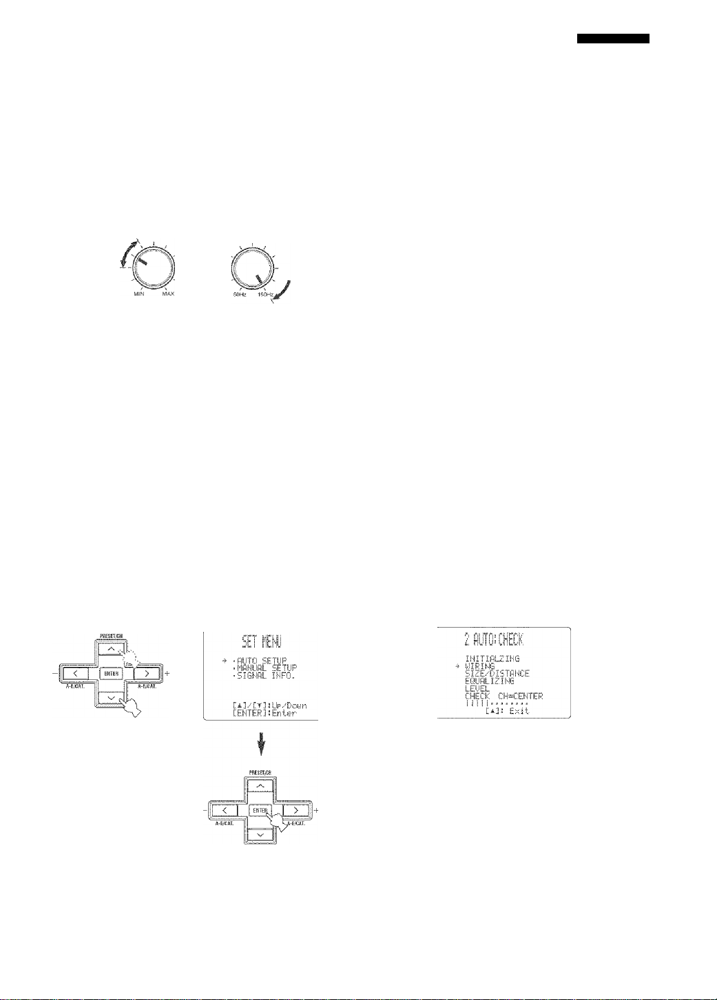
5 Press /\ / \/ to select “SETUP”, then press
< / > to select the desired setting.
Muiopf.st.ic.
O'P all it.eiiik
id LIT 0
FilELliRD
UNDO
IDIEFfiiiL!" To restore the factory preset (default)
-i'c
You can choose RELOAD or UNDO only if you have
already performed the auto setup procedure.
6 Press \/ to select “START”, then press
ENTER to start the setup procedure.
The screen changes as follows,
To perform the auto setup procedure
(YPAO).
To reload the last auto setup (YPAO)
settings to override any manual
changes.
To undo the last auto setup (YPAO)
and re.store the previous settings.
setup parameters.
When MEMORY GUARD is set to ON, you cannot select
any other SET MENU items (sec page 60).
4 Press/\ / vr to select AUTO SETUP, then
press ENTER.
NyiOiltNy
fìuÌDi'’ìaiic
processing
of ^all .it
♦
♦
EBlliiEiilT
s 5.-'4/8.,
y|:ii ii:
iiJE
.er
..'own
25
Page 30

AUTO SETUP
The results displayed in the RESULT:EXIT screen
are as follows:
The number of connected speakers
displayed in the order:
Front/Back/Subwoofer
!..i.!. b ' The distance of the speakers from this
unit displayed in the order:
Closest speaker distance/Farthest
speaker distance
The speaker output level displayed in
the order:
Lowest output level/Flighest output
level
• If you selected AUTO in step 5, ‘"WAITING”
appears when the auto setup procedure is started,
then loud test tones are output from each speaker in
turn.
• If you selected DEFAULT, RELOAD or UNDO in
step 5, no test tones are output.
• If an ERROR screen appears, see “If an error
screen appears” on page 26.
• If a WARNING screen appears, see ‘‘If a warning
screen appears” on page 27.
24}'.
You can display the detailed resull infonnalion fiy using sa and
ENTER lo select “RESULT”. In the detailed resull information
screen, you can switch information by pressing a\ / \/ / <( / ^
■ If an error screen appears
Use / </>lo select RETRY or EXIT, then press ENTER.
E-'9!LISER CfiNCEL
Dcrr’t opera
any fu net-io
>RETRV EHII
[ENTEREnter
To refry the auto setup procedure.
To exit auto setup.
7 Press < / > to select SET or CANCEL, then
press ENTER to return to the SET MENU
screen.
bi::. I To apply the auto setup (YPAO)
settings.
CliHCliEL. To cancel the auto setup (YPAO)
without making any changes.
24'i
If you are not satisfied with the result or want to manually adjust
each setup parameter, use the manual selup parameters (see
page 59).
Notes
' If E-IO appears during lesling, restart lire procedure from step 3.
' Tr cancel lire auto selup procedure before completion, press /\.
26
Page 31

If a warning screen appears
1 Press ENTER to display detailed information
about the warning.
Press <^ / 5> to switch between warning messages.
♦
W-1 warning screen
For details about each message, see page 29.
si'
* Warnings let you know about polciitial problems detected
during auto setup. Warnings wall not cancel the auto setup.
• The number of warnings is displayed to the right of
•■WARNING”.
• When Ihe warning is nol applicable lo a speaker, "—” is
displayed,
AUTO SETUP
2 When you are finished, press ENTER to
return to the RESULTiEXIT screen.
Continue from step 7 on page 26.
Notes
• If you change speakers, speaker posilions, or the layout of your
listening environment, perform auto setup again to re-calibrate
your system.
• Depending on listening environments, SWFR PHASE:REV
appears in AUTOiCHklK and SUBWOOFER PHASE
parameter in the SETMENU (see page 65) is automatically set
to REVERSE. To select the desired setting, change the
SUBWOOFER PHASE parameter in the SETMENU.
• In the DISTANCE results, the distance displayed may be longer
than the actual distance depending on the characteristics of your
subwoofer.
27
Page 32

AUTO SETUP
■ Troubleshooting for auto setup procedure
Before auto setup
Error message Cause Remedy
Corir'ieGt M]!C
Hi"'
Errors during auto setup
Error message Cause Remedy
E:.:!::H0 FfiOHT EEF'
Optimizer microphone is not connected. • Connect the supplied optimizer microphone to the
OPTIMIZER MIC jack on the front panel.
Headphones are connected. * Unplug the headphones.
Front L/R channel signal(s) is fare) not
detected.
• Select the front speakers with SPEAKERS A/B.
• Check the front left and right speaker connections.
• Turn on the power to the external amplifier (wdten tlte
front speaker signals are output from an external
amplifier).
e:
.
:;;::!iN!j suF;i?= :5F'
E:.F'REEiE,. :5E'
E:.■=!■:: ESSil?
........
>iFI3L.
Only one surround channel signal is detected. * Cheek the surround speaker connections.
Only one presence channel signal is delected. • Cheek the presence speaker connections.
Only right surround back channel signal is
detected.
• Conned Ihe surround back speaker to Ihe LEFT
SURROUND BACK SPEAKERS terminal if you
only have one surround back speaker.
« MM T cry
Background noise is loo loud. • Try Ihe auto setup procedure in a quid environment.
• Turn off noisy electric equipment like air conditioners
(etc.) or move them away from the optimizer
microphone.
pr
.
i;!m[ r‘j..J|rr‘5.;'' etj ji!|>
Surround back speaker(s) is (are) connected,
though surround L/R speakers are not.
* Conned surround speakers when you use (a)
surround back speaker(s).
• Check Ihe surround speaker connections.
e:
.
711 HO me
E:.fill: NO SIiElNfi!....
E:.EiiiUiEIEFi CifiNCE::!..
E..10:: IlfTERNMl
EJ^.0R
The optimizer microphone was unplugged
during the auto setup procedure.
The oplimizer microphone does not detect lest
tones.
The auto setup procedure was cancelled due to
user activity.
A DSP communication error or hangup
occurred.
* Do not touch the optimizer microphone during the
auto setup procedure.
• Check the microphone setting.
• Check the speaker connections and placement.
* Perform the auto setup procedure again. Do not adjust
VOLUME (etc.) during the auto setup procedure.
• Perform the auto selup procedure again.
28
Page 33

AUTO SETUP
Warnings after auto setup
Press K./y to display detailed information about individual warnings.
Warning message Cause Remedy
i.J.i: OUT OF f'diMSI:
!.j.SdiOUEF! 24iM
Speaker polarity is not eorrect. This message
may appear depending on the speakers even
when the speakers are connected correctly.
The distance between the speaker and the
listening position is 24 m (80 ft) or more.
• Check the speaker connections for proper polarity
(+/-). ^
* Move the speaker closer to the listening position.
• Cheek the speaker connections for proper polarity
(+ / -).
i.J.EliFiOF:
The difference of volume level among speakers
is excessive. (No level correction is made.)
• Readjust the speaker installation so that all speakers
are set in locations with similar conditions.
• Cheek the speaker connections for proper polarity
(+ / —)-
• Use speakers of similar quality and efficiency.
If the ERROR or WARNING screens appears, check the cause of Ihe problem, then perform the auto setup procedure again.
If warning W- ] appears, corrections are made, but they may not be optimal
If warning W-2 or W-3 appears, no corrections are made.
If error E-10 occurs repeatedly, please contact a qualified YAMAHA service center.
29
Page 34

PLAYBACK
Basic operations
(U.S.A. model)
1 3
1=
4-H' :}‘\
- - -
.;N:
i '
^ .— s yiiv -Ui',-'
1 Press STANDBY/ON (or SYSTEM POWER on
the remote control) to turn on the power.
■ e
4 Select the input source.
Rotate INPUT (or press one of the input selector
buttons on the remote control) to select the input you
desire.
I: :■(../
Front panel
The current input source name and input mode appear
in the front panel display and video monitor for a few
seconds.
DVRATCRJ VCfil V-AUX OTV/CBl DVD ’ MfcCD-R TUNED CD PHONO
Selected input source Input mode
5 start playback or select a broadcast station
on the source component.
Refer to the operating instructions for the component.
Remote control
nljr,. Pi! in. "bi
1
Front panel Remote control
2 Turn on the video monitor connected to this
unit.
3 Press SPEAKERS A or B (or press AMP to
seiect the AMP mode, then press SPEAKERS
A or B on the remote control).
Each press turns the respective speakers on or off.
SPEAKERS
L.AME_J
Front panel Remote control
6 Adjust the volume to the desired output level.
+
Remote control
A SPtejtEHS B
30
Page 35

Select a sound field program if desired.
Use PROGRAM (or press AMP to select the AMP
mode, then press one of the sound field program
buttons) to select a sound field program. See page 55
for details about sound field programs.
: AMP :
PLAYBACK
■ To mute the sound
Press MUTE on the remote control.
The MUTE indicator flashes in the
front panel display.
To resume the audio output, press
MUTE again (or press VOLUME -/+).
The MUTE indicator disappears from
the display.
PROaRAIVS
Front panel
Remote control
■ To listen with headphones (“SILENT
CINEMA”)
“SILENT CINEMA” allows you to enjoy multi-channel
music or movie sound, including Dolby Digital and DTS
surround, through ordinary headphones. “SILENT
CINEMA” activates automatically whenever you connect
headphones to the PEIONES jack while listening to
CINEMA DSP or HiFi DSP sound field programs. When
activated, the “SILENT CINEMA” indicator lights up in
the front panel display.
Notes
• This unit will not be set to “SILENT CINEMA” when MULTI
CH INPUT is selected as the input source.
• “SILENT CilNEMA” is not effective when PURE DIRECT or
the 2ch Stereo program is selected, or in STRAIGHT mode.
■ To adjust the tone
You can adjust the tonal quality
of your front left and right,
center, and subwoofer speakers or
headphones (when connected).
Press TONE CONTROL on the
front panel repeatedly to select
TREBLE or BASS, then rotate
PROGRAM to the right or left to
increase or decrease.
• Select TREBLE to adjust the
high frequency response.
• Select BASS to adjust the low'
frequency response.
TONE CONTROL
PROGRAM
s'i'i
Speaker and headphone adjusimenls are stored independently.
Notes
• TONE CONTROL is not effective during playback in the
PURE DIRECT mode, or when MULTI CH INPUT is selected
(page 31).
• When TONE BYPASS is set to “AUTO" (page 67), and BASS
and TREBLE are set to 0 dB, audio output automatically
bypasses this unit's tone control circuitry.
You can adjusl the muting level (see page 67).
■ Selecting MULTI CH INPUT
Press MULTI CH INPUT (or MULTI CH IN on the
remote control) so that “MULTI CH INPUT” appears in
the front panel display and video monitor.
Front panel
Remote control
t
■■■•I i T i. ini i'
Note
When "MULTI CH INPUT” is shown in the front panel display,
no other source can be played. To select another input source with
INPUT (or one of the input selector buttons'), press MULTI CH
INPUT (or MULTI CH IN on the remote control) to turn off
"MULTI CH INPUT" in the front panel display.
■ Playing video sources in the
background
You can combine a video image from a video source with
sound from an audio source. For example, you can enjoy
listening to classical music while viewing beautiful
scenery from the video source on the video monitor.
Use the input selector buttons on the remote control to select a video source, then select an audio source.
_ Audio sources
Video sources
Note
If you w'ant to enjoy audio from the MULTf CH INPUT jacks
together w'ith a video source, first select the video source, then
press MULTI CH INPUT (or MULTI CH IN on the remole
control i.
31
Page 36

PLAYBACK
Selecting sound field programs
Remote control operation
I Front panel operation
Rotate PROGRAM to select the desired program.
The name of the selected program appears in the front
panel display and video monitor.
PROGRAM
ports
"i i-T!.r
AMP
Press AMP to select the AMP mode, then press one of the sound field program buttons to select the desired program.
ii
Sound Held
program
buttons
The name of the selected program appears in the front
panel display.
■;0 ty . -.I." v j
‘ .. t .■ ".y.ior j
ifts,
Program name
-.1
Program name
Choose a sound field program based on your listening preference,
and not on the name of the program.
Notes
When you select an input source, this unit automatically selects
the last sound field program used with that source.
Sound field programs cannot be selected wdicn MULTI CH
INPUT is selected.
Sampling frequencies higher than 48 kHz (except for DTS 96/
24 signals) will he sampled down to 48 kHz, then sound field
programs wall he applied.
32
Page 37

PLAYBACK
■ Enjoying multi-channel software
If you connected a surround back speaker, use this feature
to enjoy 6.1/7.1-channel playback for multi-channel
sources using the Dolby Pro Logic IIx, Dolby Digital EX
or DTS-ES decoders.
Press AWIP to select the AMP mode, then press
EXTD SUR. on the remote control to switch
between 5.1 and 6.1/7.1-channel playback.
To select a decoder, press < / > repeatedly when
PLIIxMusic (etc.) is displayed.
Auto (ifUTO)
When a signal (flag) that can be recognized by the unit is
input, the unit selects the optimum decoder for playing
back the signal in 6.1/7.1 channels.
If the unit cannot recognize the flag or no flag is present in
the input signal, it cannot automatically be played in 6.1/
7.1 channels.
Decoders (select with < /»
You can select from the following decoders depending on
the format of the software you are playing.
F'LI lx flcivik'
Eor playing back Dolby Digital or DTS signals in 7.1
channels using the Pro Logic IIx movie decoder.
F'L I ]d;: !'1i...!s:i.c.
For playing back Dolby Digital or DTS signals in 6.1/7.1
channels using the Pro Logic IIx music decoder.
For playing back Dolby Digital signals in 6.1/7.1 channels
using the Dolby Digital EX decoder.
DTS signals are played back in 6.1/7.1 channels using the
DTS-ES decoder. ’ "
Notes
• Some 6.1-chaniiel compatible discs do not have a signal (Hag)
which this unit can automatically detect. Wheti playing these
kinds of discs with 6.1-chanriel. select a decoder (PLlIx Movie.
PLIlx Music, EX/ES or EX) inariually.
• 6.1-channel playback is not possible even if EXTD SUR. is
pressed in the following cases:
-When "SUR. L/R SF' (see page 63) or "SUR. B L/R SP" (see
page 64) is set to NONE.
-When the source connected to the MULTI CH INPUT jack is
being played.
-When the source being played does not contain surround left
and riglit cliannel signals.
-When a Dolby Digital KARAOKE source is being played.
-When "2ch Stereo" or PURE DIRECT is selected.
• When the pow'cr of this unit is turned off. tiiis setting will be
reset to AUTO.
• The Pro Logic IIx decoder is not available when "SUR. B L/R
SP" is set to NONE (see page 64).
• PLIIxMovie cannot be selected wfien "SUR. B L/R SP" is set to
SMLxl or LRGxI (see page 64).
■ Enjoying 2-channel software In surround
Signals input from 2-channel sources can also be played
back on multiple channels.
Press AMP to select the AMP mode, then press
STANDARD on the remote control to switch
between the SUR. STANDARD and SUR.
ENHANCED programs.
Or press MOVIE to select the MOVIE THEATER
program.
Press SELECT on the remote control to select
the decoder.
For playing back Dolby Digital or DTS signals in 6.1/7.1
channels using the Dolby Digital EX decoder
Off (OFF)
Decoders are not used to create 6.1/7.1 channels.
When "SUR. B L/R SP" is set to SMLxl or LRGxl (see
page 64). the surround back channel wall be output from the left
SURROUND BACK speaker terminals.
You can select from the following modes depending on the
type of software you are playing and your personal
preference.
33
Page 38

PLAYBACK
When you select the SUR. STANDARD program;
FliO L.OialC
Dolby Pro Logic processing for any sources.
Dolby Pro Logic II processing for movie software.
F''L..I! riusic
Dolby Pro Logic II processing for music software.
F''L..II (ii-iar'ie
Dolby Pro Logic II processing for game software.
F''L..IIx ilovie
Dolby Pro Logic IIx processing for movie software.
F''L..IIx ilusiG
Dolby Pro Logic IIx processing for music software.
F1....Í Ir;: fi-Hne
Dolby Pro Logic IIx processing for game software.
Mii'O! ?:> L! n0j''!.;!
DTS processing for movie software.
Fieoifc. iltisic
DTS processing for music software.
When you select the SUR. ENHANCED or MOVIE THEATER program:
FliO L.OiFiiC
Dolby Pro Logic processing for any sources.
F''L..II
Dolby Pro Logic II processing for movie software.
F''L..IIx ilovie
Dolby Pro Logic IIx processing for movie software.
DTS processing for movie software.
You can also select a decoder by pressing < / > on the remote
control ttdien the decoder type is displayed in the short message
display.
Note
The Pro Logic IIx decoder is not available w'hcn "SUR. B L/R
SP" is set to NONE (see pages 64).
■ Listening to high fidelity stereo sound
(PURE DIRECT)
PURE DIRECT allows you to bypass this unit’s decoders
and DSP processors, and turn off the video circuitry and
front panel display to enjoy pure high fidelity sound from
analog and PCM sources.
Press PURE DIRECT {or press AMP to select the
AMP mode, then press PURE DIRECT on the
remote control) to activate pure direct.
The indicator around the front panel button lights up.
PURE DIRECT
Front panel Remote control
The front panel display switches on inomeiharily when an
operation is performed.
To cancel, press PURE DIRECT again.
i .AMP .J PUREOmECT
The indicator around the front pane! button goes out and
the previous settings are restored.
Notes
• To avoid unexpected noise, do not. play [)TS-encodcd CDs in
this mode.
• When a rnulti-chaiinel signal (Dolby Digital or DTS) is input,
this unit automatically switches to the corresponding analog
input.
• No sound w'ill be output from the subw'oofer.
• The followung operations are not possible during PURE
DIRECT operation:
-switching the sound field program
-displaying the OSD
- adjusting SET MENU parameters
- all video functions (video conversion etc.)
• PURE DIRECT is automatically cancelled wdienevcr this unit is
sel to the standby mode.
34
Page 39

PLAYBACK
■ Night listening modes
The night listening modes are designed to improve
listenability at lower volumes or at night. Choose either
N1GHT:CTNEMA or N1GHT:MUSIC depending on the
type of material you are playing.
Press AWIP to select the AMP mode, then press
NIGHT repeatedly on the remote control to select
cinema or music.
When night listening is selected, the NIGHT indicator in
the front panel display lights up.
f AMP J NIGHT
Gjs, -
• Select NlGHTiCINEMA when watching films to
reduce the dynamic range of film soundtracks and
make dialog easier to hear at lower volumes.
• Select NIGHT:MUSIC w hen listening to music sources
to preserve ease-of-li,stening for all sounds.
• Select OEE if you do not want to use this function.
Press < / > to adjust the effect level while
NIGHTCINEMA or NIGHTMUSIC is displayed.
This adjusts the level of compression.
Remote control
■ Downmixing to 2 channels
You can enjoy 2-channel stereo playback even from multi
channel sources.
Rotate PROGRAM (or press AMP to select the
AMP mode, then press STEREO on the remote
control) to select 2ch Stereo.
PROGRAM
I AMP ! STEhEO
Front panel
Remote control
♦
You can use a subwoofer wuth this program «'hen SWFR or
BOTH is selected in "BASS OUT".
■ Listening to unprocessed input signals
In STRAIGHT mode, two channel stereo sources are
output from only the front left and right .speakers. Multi
channel sources are decoded straight into the appropriate
channels without any additional effect processing.
Press STRAIGHT (or press AMP to select the
AMP mode, then press STRAIGHT on the remote
control) to select STRAIGHT.
: AMP I
• Select MIN for minimum compression.
• Select MID for standard compression.
• Select MAX for maximum compression.
NIC;HT:CINEMA and NlCiHTAIUSIC adjustments are stored
iiidcpeiideiitly.
Notes
• You cannot use the night listening modes with PURE DIRECT
or MULTI CH INPUT (even though the NIGHT indicator lights
up when PURE DIRECT is selected).
• The night listening inodes may vary in effectiveness depentling
on the input source and surround sound settings you use.
Front panel
Remote control
I
t"" “i" l”'i r"i i”'*
.!!!* ! r's!'"!.!.
Press STRAIGHT (EFFECT) again so that “STRAIGHT”
disappears from the display when you want to turn the
sound effect back on.
■ Virtual CINEMA DSP
Virtual CINEMA DSP allows you to enjoy the CINEMA
DSP programs w'ithout .surround speakers. It creates
virtual speakers to reproduce the natural sound field.
If you set “SUR- L/R SP” to NONE (see page 63), Virtual
CINEMA DSP activates automatically whenever you
select a CINEMA DSP sound field program.
Note
Virtual CINEMA DSP «'ill not activate, even when “SUR. LR" is
set to NONE (sec page 6.3) in the following cases:
-When MULTI CH INPUT is selected as Ihe input source.
-When headphones are connected to the PHONES jack.
35
Page 40

PLAYBACK
Selecting input modes
This unit comes with a variety of input jacks. Do the
following to select the type of input signals you want to
use.
1 Rotate INPUT to select the input source.
Front panel
2 Press INPUT MODE to select an input mode.
In most cases, use AUTO.
INPUT MODE
Front panel
♦
WR.VeR2 VCR1 V-AUX DTM'CBl EWD MD-'CD-R TUNER CP PHONO
Notes
• When playing a DTS-CD/LD. he sure lo set INPUT MODE to
DTS. " "
• If the digital output data of the player has been processed in any
w'ay, you may tiot be able to perforin DTS decoding even if you
make a digital connection between this unit and the player
depending on the player.
■ Displaying information about the input
source
You can display the type, format and sampling frequency
of the current input signal.
1 Select the input source.
■!
'вЩч
Press AMP to select the AMP mode, then press STRAIGHT so that “STRAIGHT” appears in the display.
then
J)UD
______
Input source Input mode
,i:i.LiTCL
Automatically selects input signals in
the following order:
1) Digital signals*
2) Analog signals
Selects only digital .signals encoded in
DTS. If no DTS signals are input, no
I It',II II I ii.,:
sound is output.
Selects only analog signals. If no
analog signals are input, no sound is
output.
If this unil detects a Dolby Digital or DTS signal, the
decoder automatically sw-dtches to the approprithc
decoder.
You can adjust the default input mode of this unit (see page 69).
36
Page 41

Press /\ / \/ to display the following information about the input signal.
(Format) Signal format display. When the unit
cannot detect a digital signal it
automatically switches to analog input,
j. n Number of source channels in the input
signal. For example, a multi-channel
soundtrack with 3 front channels, 2
surround channels and LFE, is
displayed as '‘3/2/LFE”.
i"':;:;. Sampling frequency. When the unit is
unable to detect the sampling
frequency “Unknown” appears.
i"'.5'l:..e Bit rate. When the unit is unable to
detect the bit rate “Unknown” appears,
i"'.!. 9 Flag data encoded with DTS or Dolby
Digital signals that cue this unit to
automatically sw itch decoders.
PLAYBACK
37
Page 42

FM/AM TUNING
Automatic and manual tuning
There are 2 tuning methods; automatic and manual.
Automatic tuning is effective when station signals are
strong and there is no interference.
■ Automatic tuning
(U.S.A. model)
iO-.wli-'i
I
I
3 2
1 Rotate INPUT to select TUNER as the input
source.
Front panel
1 3
Press TUNING MODE (AUTO/MAN’L MONO) so that the AUTO indicator lights up in the front panel display.
TUMIfJQ MODE
•smm'Lnm\y
AITO
Lights up
If a colon (:) appears in the front panel display, tuning
is not possible. Press PRESET/TUNING (EDIT) to
turn the colon (:) off.
PRESET/TUNiNQ
StAfiCHMaOEff
♦
WCR? VCR1 V-AUX DTV.'CSL DVD MD-'tO-R .TUNER,
H mi 1440 kHz
4 Press PRESET/TUNING/CH o / > once to
begin automatic tuning.
Press l> to tune into a higher frequency, or press <3
to tune into a lower frequency.
PRESET/TUMirtCi/CH I--
2 Press FM/AM to select the reception band,
■‘EM” or “AM” appears in the front panel display.
Front panel
♦
HM
38
♦
(,WR2 VCFn DTV'CBl DVD f1D,'CD-R TUttER.
fl Hi1 1530 kHz
When tuned into a station, the TUNED indicator
lights up and the frequency of the received station is
shown in the front panel display.
Page 43

■ Manual tuning
If the signal from the station you want to select is weak,
tune into it manually. Manually tuning into an FM station
will automatically sw itch the tuner to monaural reception
to increase the signal quality.
1 Select TUNER and the reception band
following steps 1 and 2 as described in
“Automatic tuning”.
nVI/AM TUNING
Presetting stations
■ Automatically presetting FM stations
You can use the automatic preset tuning feature to store
EM stations. This function enables this unit to
automatically tune into FM stations with strong signals,
and to store up to 40 (8 stations in 5 groups, A1 through
E8) of those stations in order. You can then recall any
preset station easily by selecting the preset station number.
2 Press TUNING MODE {AUTO/MAN’L MONO)
so that the AUTO indicator disappears from
the front panei display.
TUNING MODE
SinS.MflB'LMSEa/
flUTO
Disappears
If a colon (:) appears in the front panel display, tuning
is not possible. Press PRESET/TUNING (EDIT) to
turn the colon (:) off.
PRESETyTUMlNG
SEARCrtWOEf
♦
V-«UX DWiCBL DVD
fill 1440 kHz
ii
Press PRESET/TUNING/CH <1/ > to tune
into the desired station manually.
Hold down the button to
continue searching.
-..•i PRESET/TUNINCS/'CH I.
C-SiBI
mmmB
: r '.-S;.! ■■ ..7C,
M-
fV
1
(U.S.A. model)
I
3 2
1 Press FM/AM to select the FM band.
Front panel
♦
Press TUNING MODE (AUTO/MAN’L MONO)
so that the AUTO indicator lights up in the
front panel display.
TUNING MODE
BISPUV ¡r
AinS.WAH'l /
flUTCi
Lights up
^■7
'ED
If a colon (:) appears in the front panel display, tuning
is not possible. Press PRESET/TUNING (EDIT) to
turn the colon (:) off.
PRESET/TUNING
SEAHCW MDDE f'
♦
VCF11 V-AUX
H liliz
39
Page 44

FM/AM TUNING
Press and hold MEMORY (MAN’UAUTO FM)
for more than 3 seconds.
The preset number, the MEMORY and AUTO
indicators flash. After about 5 seconds, automatic
presetting starts from the frequency currently
displayed and proceeds toward the higher
frequencies.
♦
BUS;VeR2 VCR1 V-AUX DTU^CBl [)VE* MapD-S ^iUNER,,.., CD,., PHONO
I
«no ffltt
.........
Mtwon/’ VOLUME
S7.5 HHz
When automatic preset tuning is completed, the front
panel display shows the frequency of the lust preset
station.
■ Manually presetting stations
You can also store up to 40 stations (8 stations in 5 groups,
A1 through E8) manually.
See page 38 for tuning instructions.
Nil 630 kHz
Notes
• Any stored station data existing under a preset number is
cleared when you store a new station under that preset number.
• If the number of received stations does not reach 40 (E8).
automatic preset tuning has automatically stopped tifler
searching all stations.
• Only FM stations with sufficient signal strength are stored
iiutornatically by automatic preset tuning. If the slalion you
want to store is weak in signal strength, tune into it manually,
and store it by followdiig the procedure in “Manually presetting
stations”.
Automatic preset tuning options:
You can select the preset number from which this unit w ill
store FM station.s and/or begin tuning toward low'er
frequencies.
After pressing MEMORY in step 3:
1 Press A/B/C/D/E, then PRESET/TUNING/CH <1 / >
to select the preset number under which the first station
will be stored. Automatic preset tuning will stop when
station.s have all been stored up to E8.
2 Press PRESET/TUNING (EDIT) to turn off the colon
{:) and then press PRESET/TUNlNG/CH <1 to begin
tuning toward the lower frequencies.
Memory back-up
The memory back-up circuit prevents the stored data
from being lost even if this unit is set in the standby
mode, the power cord is disconnected from the AC
outlet, or the power supply is temporarily cut due to
power failure. However, if the pow er is cut for more
than one week, the preset stations may be cleared. If
so, store the stations again by using the presetting
station methods.
When tuned into a station, the front panel display
show s the frequency of the station received,
2
Press MEMORY (MAN’UAUTO FM).
The MEMORY indicator flashes for about 5 seconds.
Flashes
3 Press A/B/C/D/E (NEXT) repeatedly to select
a preset station group (A to E) while the
MEMORY indicator is flashing.
The group letter appears. Check that the colon {:)
appears in the front panel display.
A/B/C/D/E
<SQ>
♦
DVR;VeR2 VCR1 V-aUX D1
JJ, iiPII 630 kHz
Preset group
40
Page 45

nVI/AM TUNING
Press PRESET/TUNING/CH <]/t> to select a
preset station number (1 to 8) while the
MEMORY indicator is fiashing.
Press t> to select a higher preset station number.
Press <3 to select a lower preset station number.
- :i PRESETrrUNtMG/CH I -
♦
DWl.tVCRZ vest V-AUX DTV'CBt DVD KD, D-R TUitER . CD. PHONO
----------------r-----------------------------------------------
Preset number
Press MEMORY (MAN’UAUTO FM) on the
front panel while the MEMORY indicator is
flashing.
Lv:LN-ii1 630iUkHz
The station band and
frequency appear in the front
panel display with the preset
group and number you have
selected.
DVB,‘tiCB2 VCR1 V-AtlX DfViiCBt. DVtCJ WO
C.3.:f5ri 630
Shows the displayed station has been stored as C3.
6 Repeat steps 1 to 5 to store other stations.
Notes
• Any stored station data existing tinder a preset number is
cleared »'hen you store a new station tinder that preset number.
• The reception mode (stereo or monaural) is stored along with
the sfafion frequency.
lUNED taElittit VOLUME
MEMORY
1
CD-R TUNER CD,.. PHONO
tOKfCi' ' " MEMCifiS VOLUt.lE
1 ¡-J 5tB
Selecting preset stations
You can tune any desired station simply by selecting the
preset station number under which it was stored.
-
When performing this operation with the remote control, first
press TUNER to set the remote to tuner mode.
1 Press A/B/C/D/E (NEXT) (or A-E/CAT. < / > on
the remote control) to select the preset
station group.
The preset group letter appears in the front pane!
display and changes each time you press the button.
A/B/C/D/E
CATEGOHY (i
Front panel
Remote control
41
Page 46

FM/AM TUNING
Press PRESET/TUNING/CH <]/[> (or
PRESET/CH / V- on the remote control) to
select a preset station number (1 to 8).
The preset group and number appear on the front
panel display along with the station band, frequency
and the TUNED indicator lights up.
i PRESET/TUNSMG/CH I
Front panel
♦
VCfn V-AUX DIV'tBt DVD MD,'CD-R TUHER CD
EUFil 37.. 5 HHz
Exchanging preset stations
You can exchange the assignment of two preset stations
with each other. The example below describes the
procedure forexchanging preset station “El” w-ith “A5”,
See “Selecting preset stations”
2 Press and hold PRESET/TUNING (EDIT) for
more than 3 seconds.
“El ” and the MEMORY indicator flash in the front
panel display.
PRESET/TUNINCa
StSBCH (.tOOE (f
♦
OURWCRf VCR1 V-AUX DW.CBl DVD H0.C8-R ,TUNER,,.,CEl.
1:1
^ R1 S
7.5 l1H2
f
42
Page 47

3 Select preset station “A5” using A/B/C/D/E
and PRESET/TUNING/CH <]/>,
“A5” and the MEMORY indicator flash in the front
panel display.
nVI/AM TUNING
A/B/C/D/E
C/Tf-GOCT (\
) PRESET/TUWr«Ci/C'M
\
DVR^CR2 VCR1 V-«UX DW'CBL DVD №CD-!! JUMER,-,, 'CD,,,
■'‘¡■"i ir II i"" ¡“."I f'i /■ i-^! I I
, ri >J r n 17 U ■ ‘O i1 n ,£l
4 Press PRESET/TUNING (EDIT) again.
The stations stored at the two preset assignments are
exchanged.
PRESET/TUNSNCS
Si.«RGH
i
i”“ PSr “1> "I" P™ .1
l:i y i I r. hi Ij
43
Page 48

XM SATELLITE RADIO TUNING
M//J3/ is XM Satellite Radio? XM Sateilite Radio connections
XM Satellite Radio is the satellite radio service with
millions of listeners across the U.S., broadcasting live
daily. XM’s ehannel lineup includes more than 130 digital
channels of choice from coast to coast: 68 commercialfree music channels, featuring hip hop to opera, classical
to country, bliiegrass to blues; 33 channels of premier
sports, talk, comedy, children’s and entertainment
programming; and more than 20 channels of the traffic
and weather information for major metropolitan areas
nationwide.
Because XM Satellite Radio is a subscription service, you
will need to set up an account and activate service with
XM using your XM Satellite Radio ID number. To check
your ID number, follow “Activating XM Satellite Radio”
on page 46. For further information on XM Satellite Radio
services, see the XM Satellite Radio website at
“
http://www'. xmradio.com”.
Notes
• The XM Salellile Radio service is only available in the 48
contiguous United States (not available in Alaska and Hawaii).
• XM Connect atid Play digital antenna accessory and monthly
subscription are sold separately. For details, see the XM
Satellite Radio website at “
http://ww«'.xmradio.com".
■ Connecting the XM Connect and Play
digital antenna accessory
Connect the XM Connect and Play digital antenna
accessory (sold separately) to the XM jack on the rear of
this unit. (For details, see the operating instructions
provided with the XM Connect and Play digital antenna
accessory),
XM jack
Notes
* For information on obtaining the XM Connect and Play digital
antenna accessory, see the website at “http://
w'ww.xmradio.com'' or visit your local retailer that sells XM
Ready products.
• To ensure optimal reception of XM’s satellite signal, the XM
Connect and Play digital antenna accessory should he placed at
or near a southerly facing window' w'ith nothing ohstructing its
path to the sky. You can mount if indoors or outdoors.
44
Page 49

XM Satellite Radio functions
This section describes the functions of each control used
for XM Satellite Radio tuning.
■ Front panel functions
Note
The following controls are only available when the unit is in the
TUNER mode and the XM Connect and Play digital anlenna
ticcessory is connected to the XM jack on the rear of this unit.
(For details, see "XM Satellite Radio connections".)
o SEARCH MODE
Switches between the All Channel Search, Category
Search, and Preset Search modes. (For details, see "XM
Satellite Radio search modes” on page 48.)
Q XM
Switches the reception band between AM, FM and XM.
0 CATEGORY (All Channel Search mode)
Changes the channel category to next one (while staying
in the All Channel Search mode).
(Category Search mode)
Changes the channel category to next one.
(Preset Search mode)
Switches between five preset groups (A to E).
o PRESET/TUNING/CH <]/I>
(All Channel Search mode)
Searches a radio channel within all channels. Press and
hold for quick search.
(Category Search mode)
Searches a radio channel within the selected category.
Press and hold for quick search.
(Preset Search mode)
Changes the preset number (1 to 8).
0
MEMORY
Switches the unit to the preset memory mode.
0
DISPLAY
Switches XM information such as channel number/name,
category, or artist name/song title displayed in the front
panel display and on-screen display. (For details, see
“Switching XM information in the front panel display” on
page 47.)
XM SATELLITE RADIO TUNING
■ Remote control functions
Note
The foliow'ing conlrols are only available when the unit is in the
TUNER mode. To swdleh to the TUNER mode, press TUNER to
select TUNER as input source.
r" ;"j (■•'h
SiSiBIS
I
I
O Numeric buttons
(All Channel Search or Category Search mode)
Use 1 to 9 and 0 to enter a channel number directly.
(Preset Search mode)
Use 1 to 8 to enter a preset channel number directly.
0
BAND
Switches the reception band between the currently
selected band (AM or FM) and XM.
o Cursor buttons y\/\/ / < / >
(All Channel Search mode)
Press A-E/CAT. ■( / > to change the channel category.
Press PRESET/CH /N / sy to search a radio channel
within all channels. Press and hold for quick search.
(Category Search mode)
Press A-E/CAT. </> to ch ange the chaiinel category.
Press PRESET/CEI /\ / v" to search a radio channel within
the selected category. Press and hold for quick search.
(Preset Search mode)
Press A-E/CAT. ■( / )> to change the preset group (A to E).
Press PRESET/CH /\ / v to change the preset number ( I to 8).
o MEMORY
Switches the unit to the preset memory mode.
0
ENT.
Confirms an entered channel number during the Direct
Number Access mode (see page 50),
0
SRCH MODE
Switches between the All Channel Search, Category
Search, and Preset Search modes. (For details, see "XM
Satellite Radio search modes” on page 48.)
0
DISPLAY
Switches XM information such as channel number/narne,
category, or artist name/song title displayed in the front panel
display and on-screen display. (For details, see “Switching XM
information in the front panel display” on page 47.)
45
Page 50

XM SATELLITE RADIO TUNING
Activating XM Sateilite Radio
To sign up for an account with the XM Satellite Radio
service, an XM Satellite Radio ID number is required.
Follow the procedure below' to check your ID number, and
then acces,s the website at “
http://activate.xniradio.com”
or call “1-800-XM-RADIO (1-800-967-2346)” with a
major credit card for signing up.
1
1 Rotate INPUT (or press TUNER on the remote
control) to select TUNER as the input source.
3 Press PRESET/TUNING/CH <3 / > (or
PRESET/CH /\ / \/ on the remote control) to
select channel “0”.
"T-y,
! PRESET/TUNING/CH
I
HITE« I |‘~T~ti +
-Si
Front panel
Note
You cannot select channel “O” if Ihe All Channel Search mode
(see page 48) is not selected.
Remote control
4 Check the XM Satellite Radio ID number
displayed in the front panel display and write
it down.
ID:
Front panel
Remote control
2 Press XM (or BAND on the remote control) to
select “XM” as the reception band.
LEVEL
Front pane!
Remote control
♦
>iPl RODIO
Lights
If “CFIECK ANTENNA” appears in the front panel
display, the XM Connect and Play digital antenna
acce.ssory may not be connected to the XM jack on
the rear of this unit properly. See “XM Satellite Radio
connections” on page 44 and check the connection.
46
Page 51

Basic XM Satellite Radio operations
I Selecting the XM Satellite Radio mode
XM SATELLITE RADIO TUNING
■ Switching XM information in the front
panel display
You can display XM information (such as channel
number/name, category, or artist name/song title) for the
channel currently selected in the front panel display.
Press DISPLAY on the unit (or remote control
during the TUNER mode) repeatedly to toggle
between the following XM information display
modes.
TUNING MODE
iUTO.WAS't f
Front panel
or
Channel name/number
Channel category
1 Rotate INPUT (or press TUNER on the remote
control) to select TUNER as the input source.
Front panel Remote control
Press XM (or BAND on the remote control) to
select “XM” as the reception band.
Information (such as channel number/name, category,
or artist name/song title) for the channel currently
selected appears in the front panel display and the
XM indicator lights up.
FM/Alui
Front panel
or
LEVEL
Bm
Remote control
♦
JUNiB.'.!
Lights
[001 3 Fl-“'-0MÌ0ld
f®'-
• Selecting the “XM" band automatically recalls the channel
previously selected.
• You can change the kind of XM information by pressing
DISPLAY repeatedly. (For details, see "Switching XM
informatitin in the front panel display” on page 47.)
Remote control
When the channel number/name is displayed:
DVRiVCR? VCRt V-AUX DTVi'CBL DVD r/ID;C»-R TUNEft^ CD
Artist name/Song title -
Tr ■-::2
When the channel category is displayed:
DI/R/VCR2 VCR1 V-ÄUX DIV/CBl DVD
g S i
When the artist name/song title is displayed:
DVfih/CFli VCRl
CcuidF-'lay / Clo
• The front panel display can indicate up to 14 alphanumeric
characters at once. If the information coiilaiiis more than 14
characters, the informalion scrolls from right to left
• If the information contains a character that cannot he
recognized by the unit, the character will be displayed with an
underbar
Note
If a status message or an error message appears in the display, see
“Status and error messages" on page 5.1.
Note
XM Satellite Radio signals cannot be output from the AUDIO
OUT (REC) jacks.
47
Page 52

XM SATELLITE RADIO TUNING
■ Displaying XM Information In the on
screen display
You can display XM information on a video monitor by
pressing DISPLAY, It is much easier to see the available
information than reading it on the front panel di.splay.
XM Satellite Radio search modes
You can search for the channel you want to listen to using
one of three search inodes. You can also enter the number
directly to select the desired channel. (For details, see
“Direct Number Access mode” on page 50.)
FILL CH SEfiRCH
KM s 040 ^
CHi-lN 3D80P (racks
cm ^Roc.k
■?< Ccidplay / Clo
C<]/C>]!iCflTEGORV
In the SET MENU (see page 71). you can set the time for
displaying XM irifonnatioii in the on-screen display.
■ When “XM DISPLAY" in the SET MENU is set to “OFF", yoti
cannot display XM information in the on-screen display.
If the information contains a character that cannot he
recognized by the unit (on-screen display program), the
character will be displayed w'ith an linderbar
■ All Channel Search mode
1 Carry out “Selecting the XM Satellite Radio
mode” on page 47.
2 Press SEARCH MODE (or SRCH MODE on
the remote control) repeatedly to select “ALL
CH SEARCH”.
PRESET/TUNiNG
Front panel
Remote control
♦
VVCFI2 VCRI V-AUX Dni«Bl DVD MD.i'Ctt-K JUiM]
48
flU.... ‘CH SEflRiJhi
Page 53

XM SATELLITE RADIO TUNING
3 To change the channel category, press
CATEGORY (or A-E/CAT. < / > on the remote
control) repeatedly.
A/B/C/D/E
CaTEGOBrr
Front panel
To search a channel within all channels,
press PRESET/TUNING/CH <a/{> (or
PRESET/CH /\ / V- on the remote control)
repeatedly.
-i PRESET/TUNSNG/CH I
nr
Front panel
You can search a channel with the quick search by pressing and
holding PRESET/TUNING/CH < / > (or PRESET/CH /\ / \a
on the remote control).
■ Category Search mode
ENTER [
A-E Í «T A-E/CAT.
Remote control
2 Press SEARCH MODE (or SRCH MODE on
the remote control) repeatedly to select “CAT
SEARCH”.
PRESET/TUNING
Front panel
Remote control
♦
DVftd/CFli VCRl V-AUX DtV/CBl DVD
ChT SEhRCH
3 To change the channel category, press
CATEGORY (or A-E/CAT. < / > on the remote
control) repeatedly.
A/B/C/D/e
MTEGPBvfi \
Front panel
To search a channel within the selected
channel category, press PRESET/TUNING/CH
<] / > (or PRESET/CH ^ / N/ on the remote
control) repeatedly.
TTI
Remote control
A.E/CAlU ^
1 Carry out “Selecting the XM Satellite Radio
mode” on page 47.
: PRESETCrUNirtG/'CH I
Front panel
Remote control
You can search a channel with the quick search by pressing and
holding PRESET/TUNING/CH d / > (or PRESET/CH /x / v
on the remote control).
49
Page 54

XM SATELLITE RADIO TUNING
■ Preset Search mode
Prior to selecting a preset channel in the Preset Search
mode, you should preset XM Satellite Radio channels. For
details, see “Setting XM Satellite Radio preset channels”
on page 51. All preset channels (A1 to E8) recalls “001
Preview” by the factory setting.
1 Carry out “Selecting the Xl\/I Satellite Radio
mode” on page 47.
2 Press SEARCH MODE (or SRCH MODE on
the remote control) repeatedly to select
“PRESET SEARCH”.
PRESET/TUNINO
Front panel
SET MENU
If MENU
SRCH mod!
Remote control
Direct Number Access mode
4
2
1 Carry out “Selecting the XM Satellite Radio
mode” on page 47.
2 Press SEARCH MODE (or SRCH MODE on
the remote control) repeatedly to select “ALL
CH SEARCH” or “CAT SEARCH”.
PRESET/rUNING
StARCftMO&Ep or
Front panel
Remote control
♦
DlVtCil ÍIVÜ
l=1?E5ET SEi:4F?i:;H
3 To change the preset group (A to E), press
CATEGORY (or A-E/CAT. < / > on the remote
control) repeatedly.
A/B/C/D/E
CATEGBRV {(
Front panel
To change the preset number (1 to 8), press
PRESET/TUNING/CH <3 /> (or PRESET/CH
/\ / V on the remote control) repeatedly.
: PRESET/TUmWG/CH I
Front panel
Remote control
Remote control
111
♦
VQRl V-AUX DTV'CBl DVD
TU!“
f
fiU.... C;H SEfiNiChl
VCRl V-AUX
f
CfTT SEfiRCH
You can also select the preset number directly by pressing the
numeric buttons (1 to 8) on the remote control.
50
Page 55

XM SATELLITE RADIO TUNING
3 Press the numeric buttons to enter the
desired channei number.
For example, to enter the number 123, pres.s the
numeric buttons as shown below.
The display changes as follows.
Tiir
<Hri> — 1
♦
OTV.iCBl [)VD
♦
:;«;ri>i23
Setting XM Satellite Radio preset channels
You can use this feature to store up to 40 XM Satellite
Radio channels (eight preset numbers in five preset
groups, A1 to E8). You can then recall any preset channel
easily by selecting the preset group and number as
described in “Preset Search inode” on page 50.
Search the XWi Satellite Radio channel you
want to set as a preset channel.
To search the desired channel, carry out “All Channel
Search mode” on page 48, “Category Search mode”
on page 49, or “Direct Number Access mode” on
page 50.
if you enter fewer than three numbers, you
may press ENT, to tune to the channei
immediateiy or wait a few seconds to confirm
the entered channei number.
‘ If no button is pressed within a few seconds after entering one
digit or two-digit number, the unit automatically confirms the
entered channel number.
‘ Pressing a button other than numeric buttons or ENT. cancels
the direct number access procedure.
C 040 3 [:>00j=- Tra
When the channel number “040” is selected
Press MEMORY on the unit (or remote
control during the TUNER mode).
The MEMORY indicator flashes for about five
seconds.
(uiEMORY
Front panel
or
Remote control
♦
HFTiriPt'
/ I \
Flashes
51
Page 56

XM SATELLITE RADIO TUNING
3 While the MEMORY indicator is flashing, press
CATEGORY (or A-E/CAT. < / > on the remote
control) to select a preset group (A to E).
The group letter appears.
A/B/C/D/E
CATtCOny (l
Front panel
or -il_lv 1- i ™
A-E,'CAT.‘
Remote control
♦
DW5/VCR2 VCm V-AUX 0TV;C&L DVD WaCD-R TUNER .. fcD<
Preset group
4 While the MEMORY indicator is flashing,
press PRESET/TUNING/CH <1 / > (or
PRESET/CH /\ / v on the remote control) to
select a preset number (1 to 8).
While the MEMORY indicator is flashing,
press MEMORY on the unit (or the remote
control) to preset the selected XM Satellite
Radio channel.
A colon appears next to the preset number for
confirmation, and the MEMORY indicator turns off.
Tart_ ^
Front panel Remote control
♦
DVftiVCB? VCRl V-AUX DTV;CBL DVD M0;'CD-R TUNER CD
Colon appears
Note
Presetting a new channel clears the former preset channel stored
in the same preset group and number.
: PRESET/TUmWG/CH I.
Front panel
Preset number
52
Page 57

XM SATELLITE RADIO TUNING
■ Status and error messages
If an operation takes longer than usual or an error occurs, one of the following messages may appear in the front panel
display. In this case, read the cause and follow the corresponding remedies.
Message Cause Remedy
|“L| j!!!' M j'J "1" |!!!' j'J kj Tj
1 ¡|!!!ii'''|nT T I'.n'llj
C 1 j'üjj'jMj
1 ¡"'i r¡ T"! '1' j'J |"!j
¡ Hm. ¡,„¡ I |m.<
/ ‘■.'i i'i'i
.
..........
j"'' Tj "r
..................
The XM Conned and Play digital aiitennii
accessory is not connected, or does not work
properly.
The XM user encryption code is being updated. • Wait until the encryption code is updated.
The signal is too weak. • Check the XM Connect and Play digital antenna
It lakes longer than four seconds for audio or
text data to be decoded.
The XM .Satellite Radio channel you selected is
not currently broadcasting any signal.
The channel station ID (S'lD) is no longer
available.
No artist naine/leature or song/prograin title is
available.
No channels arc avidlablc for the selected
category.
• Check the XM C’onnect and Play digital antenna
accessory connections.
accessory connections and orient it for the best
reception.
• Wait until the decoding process has finished.
• Check the channel number again or select another
XM Satellite Radio channel.
• Select another channel category by pressing
CATEGORY (.01- A-E/CAT. < / > on the reinóte
control) repeatedly.
53
Page 58

RECORDING
Recording adjustments and other operations are
performed from the recording components. Refer to the
operating instructions for those components.
. • •• • • •
iaiv Ic:
...............................
......................
: . . •
-i/TjU-UfTAT
.
w : 'v' wO.- . j
.T
.....
■■
. ■. / ]j : :
. .-A
{U.S.A. model)
1 Turn on the power of this unit and all
connected components.
2 Select the source component you want to
record from.
Notes
• When this unit is set in the standby mode, you cannot record
between other components connected to this unit.
• The setting of TONE CONTROL, VOLUME, "SPEAKER
LEVEL" (page 65) and programs does not affect recorded
material.
• A source connected to the MULTI CH INPUT jacks of this unit
cannot be recorded.
• S~video and composite video signals pass independently
through this unit's video circuits. Therefore, when recording or
dubbing video signals, if your video source component is
connected to provide only an S-video (or only a composite
video) signal, you can record only an S-video (or only a
composite video) signal to your VCR.
• Digital signals input to the DIGITAL INPUT jacks are not
output to the analog AUDIO OUT (L/R) jacks for recording.
Likewise, analog signals input to the AUDIO IN (L/R) jacks are
not output to the DIGITAL OUTPUT jack. Therefore, if your
source component is connected to provide only digital (or
analog) signals, you can only record digital (or analog) signals.
• A given input source is not output on the same REC OUT
channel, (For example, the signal inptil from VCR I IN is not
output on VCR I OUT.)
• Check the copyright laws in your country to record from
records, CDs, radio, etc. Recording of copyrighted material may
infringe copyright laws.
If yon playback a video .source that uses scrambled or
encoded signals to prevent it from being dubbed, the
picture itself may be disturbed due to those signals.
a
:''
Front panel
3 Start playback (or select a broadcast station)
on the source component.
4 Start recording on the recording component.
Do a fesl recording before you start an actual recording
Remote control
■m: \
O '
Oi ■ i
■ Special considerations when recording
DTS software
The DTS signal is a digital bitstream. Attempting to
digitally record the DTS bitstream will result in noise
being recorded. Therefore, if you want to use this unit to
record sources that have DTS signals recorded on them,
the following considerations and adjustments need to be
made.
For DVDs and CDs encoded with DTS, when your player
is compatible with the DTS format, follow its operating
instructions to make a setting so that the analog signal will
be output from the player.
54
Page 59

SOUND FIELD PROGRAM DESCRIPTIONS
This unit is equipped with a variety of precise digital decoders that allow you to enjoy multi-channel playback from
almost any sound source (stereo or multi-channel). This unit is also equipped with a YAMAHA digital sound field
proce,ssing (DSP) chip containing several sound field programs which you can use to enhance your playback experience.
Most of these sound field programs are precise digital recreations of actual acoustic environments found in famous
concert halls, music venues, and movie theaters.
Tlie YAMAHA CINEMA DSP modes are compatible with all Dolby Digital. DTS. and Dolby Surround sources. Set the input mode to
AUTO (see page 36) to enable this unit to aulomiiliciilly switch to the appropriate digital decoder according to the input signal.
Notes
• This unit’s DSP sound field programs are recreations ofreal-w'orld acoustic environments made from precise measurements taken in
the actual hall. etc. Thus you may notice variations in the strength of the renections coming from the front, back, left and right.
• Feel free to choose a sound field program based on your listening preference, and not purely on the name of the program itself.
For movie/video sources
You can select from the following sound fields when playing movie or video sources. The sound fields marked “MULTI”
can be used with multi-channel sources, like DVD, digital TV, etc. Those marked “2-CH” can be used with 2-channel
(stereo) sources like TV programs, video tapes, etc.
Program selection methods vary depending on sound field program types. For details on how to select sound field programs, see “Selecting sound field programs” on pages 32 to 35.
Remote
control
button
1
2
Program Features Sources
S'llERlEiJ:
Yiii-h
riUSiC:
Downrnixes iniilti“Channel sources to 2 channels (left and right) or plays back 2“Chaiine]
sources as is.
This program lends an enthusiastic atmosphere to the sound, giving you the feeling you are at
an actual jaz/ or rock concert-
Eli IE FrrR I
E!TTEf<!Hlri!lEri!;
3
f'iijnu ilO'diti
EllTEfEiRIililEr-r!:
Though the presence sound field is relatively narrow, the surround sound field employs the
sound environment of a large concert hall. This effect enhances the experience of watching
various TV programs such as news, variety shows, music programs or sporT.s programs.
This program is provided for reproducing monaural video sources (such as old movies). The
program produces the optimum reverberation to create sound depth using only the presernce
sound field-
This program adds a deep and spatial feeling to video game sounds.
MULTI
2-CH
55
Page 60

SOUND FIELD PROGRAM DESCRIPTIONS
Remote
control
button
Program Features Sources
HOUIE: ■rEIEiJTlER:
E'F-eGt.^íicl e
CINEMA DSP pi'occf^sing. This program creates the extremely wide sound field of a 7Ü-inin
movie theater. It precisely reproduces the source sound in detail, making both the video and
the sound field incredibly real. This is ideal for any kind of video source encoded with Dolby
Surround. Dolby Digital or DTS (especially large-scale movie productions).
riOUIE: ■ri"iE!4 !lER:
•! ..... t... >1
CINEMA DSP processing. This program clearly reproduces dialog and sound effects in the
latest sound form for science fiction films, thus creating a broad and expansive cinematic
space amid silence. You can enjoy science fiction films in a virtual-space sound field that
4
|'i'|j'''jj i'[ C' 'rLjprV'r'u'p.
Uijil' 1'”! Vi.j
includes Dolby Surround, Dolby Digital and DTS-encoded software employing the most
advanced techni(]ues.
CINEMA DSP processing. This program is ideal for precisely reproducing the sound design
of the newest 70-mm and multi-channel soundtrack films. The sound field is made to be
similar to that of the newest movie theaters, so the reverberations of the sound field itself are
restrained as much as possible.
flou I E: "n-IElJTER:
.1
E:ì...ìR= ErrfìHIOfìRD
5
S:ì...ìR:: lElihlHliCfED
CINEMA DSP processing. This program is for reproducing sounds from 70-mm and multi
channel soundtrack films, and is characterized by soft and extensive sound field.
Standard processing for the selected decoder.
Enhanced processing for the selected decoder.
MULTI
2-CH
56
Page 61

SOUND FIELD PROGRAM DESCRIPTIONS
For music sources
You can select from the following sound fields when playing music sources, like CD, FM/AM broadcasting, tapes, etc.
Program selection methods vary depending on sound field program types. For details on how to select sound field programs, see “Selecting sound field programs” on pages 32 to 35.
Remote
control
button
Program Features Sources
CjTu' jiji'Lr j'“j.
2-chaiine] (left and right) playback.
1
^ t j... j 1 .
i:
h'jj |C T ,
h'jj jC T j"“'.
2
hij |C 'i' ,
|!!!' "j" |!!!' Tj 'i' j'J j'ri jl!!' l'..| .
3
CJ1 1 u' "r Tj kj rS M u' rS
5
Cj j j j!!!' u j'.J Li f"j j'“' j!!!” ¡“•s
Use to increase the OLitpui stereo sources (in stereo) from all speakers. This provides a
larger sound field and is ideal lor background music at parties, etc.
HiFi DSP processing. A classie shoe-box type eoncert hall with approximately 1700
seats. Pillars and ornate carvings create extremely complex reflections which produce
a veiy' full, rich sound.
HiFi DSP processing. This is the sound field at stage front in "The Bottom Line'k a
famous New York jazz club. The tloor can seat 300 people to the left and right in a
sound field offering a real and vibrant sound.
HiFi DSP processing. The ideal program for lively, dynamic rock music. The dtita for
this program was recorded at LA’s "hottest” rock club. The listener’s virtual seat is at
the center-left of the hall.
HiFi DSP processing. This program recreates the acoustic environment of a lively
disco in the heart of a big city. The sound is dense and highly concentrated. It is also
characterized by high-energy, "immediate” sound.
Standard processing for the selected decoder.
Enhanced processing for the selected decoder.
2A'H
MULTI
2.CH
57
Page 62

ADVANCED OPERATIONS
Selecting the OSD mode
You can display this unit’s operating information on a
video monitor. If you display the SET MENU and sound
field program parameter settings on a monitor, it is much
easier to see the available options and parameters than it is
by reading this information on the front panel display.
1 Turn on the video monitor connected to this
unit.
Z Press ON SCREEN repeatedly to change the
OSD mode.
The OSD mode changes in the
following order: full display, short
display, and display off.
Full display
Always shows the sound field program parameter settings
as w ell as the contents of the front panel display.
Short display
Briefly Show' S the contents of the front panel display at the
bottom of the screen each time you operate this unit.
Display off
Only operations performed using ON SCREEN are
displayed. The OSD is displayed when using SET MENU
even if the OSD mode is set to “Display off’.
P04 miETHEPTER
' PEvhÌIS:ìÌS:
yi'iufi
P04 HOUIE THEPTER
Using the steep timer
Use this feature to automatically set this unit in the
standby mode after a certain amount of time. The sleep
timer is useful when you are going to sleep while this unit
is playing or recording a source. The sleep timer also
automatically turns off any external components
connected to AC OUTLET(S).
■ Setting the sleep timer
1 Select a source and start playback on the
source component.
Press SLEEP repeatedly to set the amount of time.
Each time you press SLEEP, the front
panel display changes as shown
below. The SLEEP indicator flashes
while switching the amount of time
for the sleep timer.
-A SLEEP ITOinin SLEEP POmiii
SLEEP OFF C SLEEP .fOmin U SLEEP 6()niin
Full display Short display
Notes
• The OvSD signal is not output to Ihe REC OUT jack, and will
not be recorded.
• You can set the OSf) to turn on (gray background) or off w-'heii a
video source is not being reproduced (or the source component
is turned off) by using [)ISPLAY SET (see page 70).
• When only the component video signals arc input, tire OSD is
not displayed if the OSD mode is set to "Short display". To
display the OSD witli component video signal input, set the
OSD mode to “Full display" while GRAY BACK in DISPLAY
SET (see page 70) is set to AUTO.
58
ii-EEP 12Eir-iin
The SLEEP indicator lights up in the front panel
display, and the di.splay returns to the selected sound
field program.
DVftiVCRJ VCR1 V-AUX OTV/CEIL DVD
gp ^ IciSir.MA-HtS
SLEEP indicator
I
Tl
Page 63

■ Canceling the sleep timer
Press SLEEP repeatedly until '‘SEEEP OFF” appears in
the front pane! display.
After a few seconds, “SEEEP OFF” disappears, and the
SLEEP indicator coes off.
SLEEP
The sleep timer setting can also be canceled by pressing
STANDBY on the remote control (or STANE)BY/ON on tire front
panel) lo set this unit to the standby mode.
ADVANCED OPERATIONS
Manually adjusting speaker levels
You can adjust the output level of each speaker while
listening to a music source. This is also possible when
playing .sources through the MULTI CH INPUT jacks.
Please note that this operation will override the level
adjustments made in “AUTO SETUP” (page 24),
“SPEAKER LEVEL” (page 65). "
■3
1 Press AMP.
2 Press LEVEL repeatedly to select the
speaker you want to adjust.
•''! I !
r kj T lmD
l-.JI!j
Front left speaker level
Center speaker level
Front right speaker level
Surround right speaker level
Surround back right speaker level
Surround back left speaker level
Surround left speaker level
Subwoofer level
Presence left speaker level
Presence right speaker level
Once you press LEVEL, you can also select the speaker by
pressing as / v-.
3 Press < / > to adjust the speaker output level.
The control range is from +10 dB to -10 dB.
4 Press ENTER when you have completed your
adjustment.
This operation can also be performed using the controls on the
front panel. Press NEXT repeatedly to select the speaker you
want to adjust, then press LEVEL-/+ to adjust the output level.
59
Page 64

SET MENU
You can use the following parameters in SET MENU to adjust a variety of system settings and customize the way this
unit operates. Change the initial settings (indicated in bold under each parameter) to reflect the needs of your listening
environment.
■ AUTO SETUP
Use to specify which speaker parameters auto setup will adjust, and to activate the auto setup procedure (see page 24).
■ MANUAL SETUP
Use to manually adjust speaker and system parameters.
1 SOUND MENU
Use to manually adjust any speaker setting, alter the quality and tone of the sound output by the system or compensate for
video signal processing delays when using ECD monitors or projectors.
Most of the parameters described in SOUND MENU are set automatically when you run auto setup (see page 24). You can use SOUNE)
MENU to make furlher adjustments, but ws recommend running auto setup first.
Item Features Page
ITiiSPIEijKEF; SlE'l
[TuBI-dEfiKEF; LEliEl...
OSP CulSTldNCE:
lEiiLFE: LEliEL
Selects the size of each speaker, the speakers for low-freciiieney signal output, and the cross over
frequency.
Adjusts the out.piil level of each speaker. 65
Adjusts the delay time of each speaker. 66
Adjusts the tonal quality of the center speaker. 66
Adjusts the output level of the LFE channel for Dolby Digital or DTS signals. 67
RijhliBIE
6)iiUi)I0 SET
2 INPUT MENU
Adjusts the dynamic range for Dolby Digital or DTS signals. 67
Customizes the muting level, audio delay and tone bypass settings. 67
Use to reassign digital input/outputs, select the input mode or rename your inputs.
Item Features Page
iViLNl MivEilGHnlEiT!
EOIH|:d„JT i'lCiDsE
!j:JiHid..JT FilENfirlE Changes the name of the inputs. 69
D)U0!.J..iiiE TFilfl
Assigns jacks according to the component to be used.
Selects the initial input mode of the source.
Adjusts the output voliiine of each jack.
68
69
69
60
Page 65

3 OPTION MENU
Use to adjust the optional system parameters.
Item Features Page
ij ■-! ¡“i'¡'i""¡;;;iI
i!j '"i j'ljj inpi'''j
j'"' ’’i T M '[
ri''|M||l TT '!!ri!!!"r
I!!!'''i'v'ivj pi"n"'| T >ru''r
Adjusts the brighi.ncss of the display and convert.s video signals.
Locks sound field program parameters and other SET MENU settings. 70
Initializes the parameters of a group of sound field programs.
Specifies the location of the speakers connected to the SPEAKERS B terminals. 7I
Displays the current reception level for the XM Connect and Play digital antenna accessory. 71
■ SIGNAL INFO
Use to check audio Signal information (see page 36).
SET MENU
70
7I
61
Page 66

SET MENU
Using SET MENU
Use the remote control to access and adjust each
parameter.
1*1
■3-7
• You can change SET MENU parameters while tlie unit is
reproducing sound.
• If you press a sound field program butlon during SET MENU
operation, the SET MENU is canceled.
Note
You cannot change some SET MENU parameters while the unit
is in either cinema or music night listening mode.
1 Press AMP.
4 Press ENTER to enter MANUAL SETUP.
1 SOUND MENU appear.s on the front panel display.
D MEHLI
ENTER
■ X
'-------
A-E,'CAT. La-E;CAT.
-
r
2 INPUT MENU
3 OPTION MENU
[ir-'[T'!Up--'Doir
[ENTER]:Enter
5 Press /\ / \/ to select the desired menu.
6 Press ENTER to enter the selected menu.
PRiSETyCH
A 1
XT
y™X[X]|+“*^
А-Е/СДТ. NA-EfCAT.
R
7 Press /\ / \/ and ENTER to select the
submenu, then press /\/\/to select the item and < / > to change the parameter.
2 Press SET MENU.
3 Press y\/\y to select M AN UAL SETU P.
= ЙМТП SETilP
= MPNLIFIL SE:TUF
QX
^SlGHhl INFlU
[ ENTER ]Xnt&r
• Repeat this operation to select and adjust each
setting.
• To return to the previous menu level, press
RETURN.
8 To exit, press SET MENU when finished.
Memory back-up
The memory back-up circuit prevents the stored data
from being lost even if this unit is in the standby mode.
However, if the power cord is disconnected from the
AC outlet, or the power supply is cut for more than one
week, the stored data will be lost. If so, adjust the
items again.
62
Page 67

1 SOUND MENU
Use to manually adjust any speaker setting or compensate for
video signal processing delays when using LCD monitors or
projectors. Most of the SOUND MENU parameters are set
automatically when you mn auto setup (see page 24).
■ Speaker settings MjSFdEMKEtFi SIET
U.se to manually adju.st any speaker setting.
Sfiii
If you are not satisfied with the bass sounds from your speakers,
you can change these settings according to your preference.
Front speakers Fd'<0i-H" iFF'
Choices: LARGE, SMALL
SET MENU
Center speaker CEITI'liEi?
Choice.s: ERG, SML, NONE
• Select ERG if you have a large center speaker. The unit
directs the entire range of the center channel signal to
the center speaker.
• Select SML if you have a small cetiter speaker. The unit
directs the low'-frequency signals of the center channel to
the speakers selected with “LFE/BASS OUT”.
• Select NONE if you do not have a center speaker. The
unit directs all of the center channel signal to the front
left and right speaker,s.
Surround left/right speakers SUFi . L R SF'
Choices: ERG. SML, NONE
FHONI SP
■1 sPlh
/ ft
SriRLL I^LfiRGE
Select SMALL if you have small front speakers. The
unit directs the low-frequency signals of the front
channel to the speakers selected with “LFE/BASS
OUT”.
Select LARGE if you have large front speakers. The
unit directs the entire range of the front left and right
channel signals to the front left and right .speakers.
Select ERG if you have large .surround left and right
speakers. The entire range of the surround channel
signal is directed to the surround left and right
speakers.
Select SML if you have small surround left and right
speakers. The low-frequency signals of the surround
channel are directed to the speakers selected with
“LFE/BASS OUT”.
Select NONE if you do not have surround speakers.
This will set the unit to the Virtual CINEMA DSP
mode (see page 35) and automatically set the surround
back speaker setting (SUR. B L/R SP) to NONE.
63
Page 68

SET MENU
Surround back speakers SiJF!= l::M, R SF'
Choices: LRGx2, LRGxl, SMLx2, SMLxL NONE
• Select LRGx 1 if you have a large surround back
speaker. The unit directs the entire range of the
surround back channel signal to the left surround back
speaker.
• Select LRGx2 if you have 2 large surround back
speakers. The unit directs the entire range of the
surround back channel signal to the surround back
speakers.
• Select SMLx2 if you have 2 small surround back
speakers. The low-frequency signals of the surround
back channels are directed to the speakers selected with
■‘LFE/BASS OUT”.
• Select SMLx 1 if you have a small surround back
speaker. The low-frequency signals of the surround
back channel are directed to the speakers selected with
“LFE/BASS OUT”, and the rest of the frequency
signals are directed to the left surround back speaker.
• Select NONE if you do not have a surround back
speaker. The unit directs all of the surround back
channel signal to the surround left and right speakers.
Noto
If you select SMLx I or LRGx I, connect the speaker to the left
SURROUND BACK speaker terminals.
Presence speakers EtSIEi-liii: i:;!'-'
Choices: YES, NONE
Bass out LJ-diE-rlBifiVo OUT
Low-frequency (bass) signals can be directed to the
subwoofer and/or the front left and right speakers
according to the characteristics of your system. This
setting also determines the routing of the LFE (low -
frequency effect) signals found in Dolby Digital or DTS
sources.
Choices: SWFR, FRNT, BOTH
• Select SWFR if you connect a subwoofer. LFE and
low-frequency signals from other channels are directed
to the subwoofer according to the speaker settings.
• Select FRNT if you do not use a subwoofer. LFE and
low frequency signals from other channels are directed
to the front speakers according to the speaker settings
(even if you have previously set front speakers to
SML).
• Select BOTFl if you connect a subwoofer and you want
to output low-frequency signals from front channels to
both the front speakers and subwoofer. LFE and lowfrequency signals from other channels are also directed
to the subw oofer according to the speaker settings. Use
this function to reinforce low-frequency signals using
the subwoofer when playing back sources such as CDs.
Cross over iJlROiVo OuEF!
Use this feature to select a cross-over (cut-off) frequency
for all low-frequency signals. All frequencies below- the
selected frequency will be sent to the subwoofer.
Choices: 40Hz, 60Hz, 80Hz, 90Hz, lOOHz, 1 lOHz,
120Hz, 160Hz, 200Hz
pl's'l.
■ A \
Select YES if you have presence speakers.
Select NONE if you do not have presence speakers.
When YES is selected, the unit automatically adjusts the dialog
lift parameter. To adjust it manually, see page 83.
64
Page 69

SET MENU
Subwoofer phase !5iJE!iiL)!Ji“EF! FlifiSt:
If bass sounds are lacking or unclear, use this feature to
switch the phase of your subwoofer.
Choices: NORMAL, REVERSE
• Select NORMAL if you do not want to reverse the
phase of your subwoofer.
• Select REVERSE to reverse the phase of your
subwoofer.
Presence/Surround back channel priority
You can select to prioritize either the surround back or
presence speakers when playing sources that contain
surround back channel signals using CINEMA DSP sound
field programs.
Choices: PRch, SBch
,UsU;
■ Speaker level l:iL5Fd:E("!i<IEi< [..EEUEd..,.
Use these settings to manually balance the speaker levels
between the front left or surround left speakers and each
speaker selected in SPEAKER SET (page 63).
Choices: -10.0 dB to +10.0 dB
Initial Setting: 0 dB
1' '.
FL adjusts the balance of the front left speaker.
FR adjusts the balance of the front right speaker.
C adjusts the balance of the center speaker.
SL adjusts the balance of the surround left speaker.
SR adjusts the balance of the surround right speaker.
SBL* adjusts the balance of the surround back left
speaker.
SBR* adjusts the balance of the surround back right
speaker.
SWFR adjusts the balance of the subwoofer.
PL adj lists the balance of the presence left speaker.
PR adjusts the balance of the presence right speaker.
Instead of SBL and SBR, SB wall be displayed if you selected
only one surround back speaker in SUR, B L/R SP (page 64).
Select PRch to use presence speakers even when
surround back channel signals are input. The signals
for the surround back channel will be output from
surround speakers.
Select SBch to use surround back speakers when a
surround back channel signal is detected in a CINEMA
DSP program. Presence channel signals will be output
from front speakers.
65
Page 70

SET MENU
■ Speaker distance C):5P DISThHCIE
Use this feature to manually input the distance of each
speaker and adjust the delay applied to respective channel.
Ideally, each speaker should be the same distance from the
main listening position. However, this is not possible in
most home situations. Thus, a certain amount of delay
must be applied to the sound from each speaker so that all
sound will arrive at the listening position at the same time.
Unit UNÎT
Choices: meters (m), feet (ft)
Initial setting: feet (ft)
• Select meters to input speaker distances in meters.
• Select feet to input speaker distances in feet.
Speaker distances
Choices; 0.3 to 24.00 m (1 to 80 ft)
• FRONT Ladj lists the distance of the front left speaker.
Initial setting: 3.0 ni (10.0 ft)
• FRONT R adjusts the distance of the front right
speaker. Initial setting: 3.0 in (10.0 ft)
• CENTER adjusts the distance of the center speaker.
Initial setting: 3.0 m (10.0 ft)
• SUR. L adjusts the distance of the surround left
speaker. Initial setting: 3.0 m (10.0 ft)
• SUR. R adjusts the distance of the surround right
speaker. Initial setting: 3.0 m (10.0 ft)
• SB L* adjusts the distance of the surround back left
speaker. Initial setting: 2.10 in (7.0 ft)
• SB R* adj u,sts the distance of the surround back right
speaker. Initial setting: 2.10 m (7.0 ft)
• SWFR adjusts the distance of the subwoofer. Initial
setting: 3.0 m (10.0 ft)
• PRESL adjusts the distance of the presence left
speaker. Initial setting: 3.0 m (10.0 ft)
• PRES R adjusts the distance of the presence right
speaker. Initial setting: 3.0 m (10.0 ft)
• Instead of SB L and SB R. SUR. B will be displayed if you
selected only one surround back speaker in SUR. B L/R SP
(page 64).
■ Center graphic equalizer [fJEQUf"!' ‘ i "
Use this feature to select the parametric (AUTO PEQ) or
graphic equalizer (CNTR GEQ).
Equalizer lEiJ TvF'E SlELJECiT
Select to change the type of equalizer u.sed by this unit.
Choices: AUTO PEQ, CNTR GEQ, EQ OFF
• Select AUTO PEQ to use the equalizer adjusted in auto
setup.
• Select CNTR GEQ to adjust the built-in 5-band graphic
equalizer so that the tonal quality of the center speaker
matches that of the front left and right speakers.
• Select EQ OFF to cancel equalizing.
Center graphic equalizer CiEhlTIEf? 6EQ
When CNTR GEQ is selected, use this feature to output a
test tone and adjust the tonal quality so that it matches that
of the front left speaker.
You can adjust 5 frequency bands:
lOOHz, 300Hz, 1 kHz, 3kHz, lOkHz
Choices: -6 to -1-6 dB
Initial setting: 0 dB
COEGUPLIZER
T'EST MDF'F OH
Select ON to output test tones from the front left and
center speakers, and adjust the tonal quality of the
center speaker.
Select OFF to .stop the test tone and output the
currently selected source component.
Press /\ / xz to select a frequency band.
Press <( / )> to adjust the selected frequency band.
66
Page 71

SET MENU
■ Low-frequency effect level E)i....Fn:E LIEUEL
Use to adjust the output level of the LFE (low-frequency
effect) channel according to the capacity of your
subwoofer or headphones. The LFE channel carries lowfrequency special effects which are only added to certain
scenes. This setting is effective only when this unit
decodes Dolby Digital or DTS signals.
Choices: -20 to 0 dB
Speaker EiFdEHKIEFi;
Select to adjust the speaker LFE level.
Headphone liEd'jidFlHOhlE
Select to adjust the headphone LFE level.
Note
Depending on the settings of "LFE LEVEL", some signals may
not be output from the SUBWOOFER OUTPUT jack,
■ Dynamic range FEujffNMrIIC IEQH6E:
Use to select the amount of dynamic range compression to
be applied to your speakers or headphones. This setting is
effective only when the unit is decoding Dolby Digital and
DTS signals.
Choices: MIN (minimuin), STD (standard), MAX
(maximum)
■ Audio settings h)RUDIu SIET
Use to customize this units overall audio settinas.
MU T I N6 т у р е ; . . F U L L
AU D I O D E L f l V - -0i4S
TO N E B V P A b S - - A U T O
[i ] . - t T j ! U p . - ' D o w n
г <1.- ' [ > ] ! S e l e c t
Muting type flUTIHG TyFiE
Use to adjust how much the mute function reduces the
output volume.
Choices: FULL, -20dB
• Select FULL to completely halt all output of sound.
• Select -20dB to reduce the current volume by 20 dB.
Audio delay hUE)I0 DIELhS'
Use to delay the sound output and synchronize it with the
video image. This may be necessary when using certain
LCD monitors or projectors.
Choices: 0 to 160 ms
Tone bypass 'Г0Ы1Е BvFldS:5
Use to select whether audio output bypasses tone control
circuitry when TREBLE and BASS are set to 0 dB (see
page 31).
Choices: AUTO, OFF
• Select AUTO if you want signals to bypass tone
control circuitry to provide the pure.st signal possible.
• Select OFF if you do not want signals to bypass tone
control circuitry.
Speaker
Select to adjust the speaker compression.
Headphone HF
Select to adjust the headphone compression.
• Select MIN if you regularly listen at low volume
levels.
• Select STD for general use,
• Select MAX to preserve the greatest amount of
dynamic range.
67
Page 72

SET MENU
2 INPUT MENU
Use to reassign digital input/oiitpiits, select the input mode
or rename your inputs.
For OPTICAL INPUT jack 2 (OP T I! Cil... I! N (2)),
3(0PTIChL in c3>) arid 4 (OPTIChL IN (4 ))
Choices: (2) CD. MD/CD-R, DVD, DTV/CBL, VCRL
DVR/VCR2
(3) CD, MD/CD-R. DVD, DTV/CBL, VCRl.
DVR/VCR2
(4) CD, MD/CD-R. DVD, DTV/CBL, VCRl,
DVR/VCR2
Input/output assignment
I u... Ц., I I'.i
You can assign jacks according to the component to be
used if this unit’s initial settings do not correspond to your
needs. Change the following parameters to reassign the
respective jack.s and effectively connect more
components.
Once the inputs have been reassigned, you can select the
corresponding component by using INPUT on the front
panel or the input selector buttons on the remote control.
For COMPONENT VIDEO jacks A (CI1F i! i...........U
INPUT [fl]) arid B (Ci'jPHT
............
U INPUT [B])
Choices: [A] DVD, DTV/CBL, V-AUX, VCRl,
DVR/VCR2
[Bj DVD, DTV/CBL, V-AUX, VCRl,
DVR/VCR2
For OPTICAL OUTPUT jack 1 (OPTICfiL OUT Ci ))
Choices: CD, MD/CD-R, DVD, DTV/CBL,
V-AUX. VCRl, DVR/VCR2
For COAXIAL INPUT jacks 5 (CiiflN Iiil. i N :! 5 >)
arid 6 (COfiNIfli.... IN C 6>)
Choices: (5) CD, MD/CD-R, DVD, DTV/CBL, V-AUX,
VCRl, DVR/VCR2
(6) CD, MD/CD-R, DVD, DTV/CBL, V-AUX,
VCRl, DVR/VCR2
Nqt^S
• You cannot select a specific item more than once for the same
type of jack.
• When you connect a component to both the COAXIAL and
OPTICAL jacks, priority is given to the input signals from the
COAXIAL jack. "
68
Page 73

SET MENU
■ Input mode BV[HF''UT f'luDE
Use this feature to designate the input mode for sources
connected to the DIGITAL INPUT jacks when you turn on
this unit (see page 36 for details about the input mode).
Choices: AUTO, LAST
• Select AUTO to allow this unit to automatically detect
the type of input signal and select the appropriate input
mode.
• Select LAST to set this unit to automatically select the
last input mode used for that source.
Note ;
Even if LAST is selected, the last setting for the EX/ES button
will not be reailled.
■ Input rename C)IHFd.„iT REHflnE
Use this feature to change the name of the inputs on the
OSD and front panel di.splay.
■ Volume Trim [UiU0!.J...il1E TFilrl
Use this feature to adjust the level of the signal input to
each jack. This is useful if you want to balance the level of
each input source to avoid sudden changes in volume
when switching between input sources.
Choices: CD, MD/CD-R, TUNER, DVD, DTV/CBL,
V-AUX, VCRl. DVR/VCR2
OlifUl EiliE
-> Ai®
C<]/C>jSpuSltlGri
[A]/[Tj I Lhar'-a.,
1 Press an input selector button to select the
input you want to change the name of.
Press AMP.
3 Press < / > to place the _ (under-bar) under
the space or the character you want to edit.
4 Press /\ / \/ to select the character you want,
then use < / > to move to the next space.
• You can u.se up to 8 characters for each input.
• Press \/ to change the character in the following
order, or press /A to go in the reverse order:
A to Z, a space, 0 to 9, a space, a to z, a space,
symbols (#, *, +, etc.).
5 Repeat steps 1 through 4 to rename each
input.
_
6 To exit, press SET MENU when finished.
69
Page 74

SET MENU
3 OPTION MENU
Use to adjust the optional system parameters.
DTinU
fOl
ISPLflV SET
EI10RV GLIhlRD
PRRM,, I Hi
V.'i-
ILTT ZHNF '^ET
: lb .
TER]-Enter
settings fi>[u:SFi,.,.£:!v ;
isplhv set
GRh
E^-3
[<3 --C>3i SELECT
Dimmer DlflillEi?
Use to adjust the brightness of the front panel display.
Choices: -4 to 0
Video conversion UIDIEO COHU.
Use this feature to turn on/off conversion of composite
(VIDEO) signals to both S-video and component signals.
This allows you to output converted video signals from
the S VIDEO or COMPONENT VIDEO jacks when no
S-video or component signals are input. This feature also
converts S-Video signals to component signals when no
component signals are input.
Choices: ON, OEF
• Select OFF not to convert any signals (except S-video
signals to composite signals).
• Select ON to convert composite signals to S-video and
component signals, and to convert S-video signals to
component signals.
• Regardless of the setting, S-video signals are always
converted to composite signals.
Notes
• Converted video signals are only output to the MONITOR OUT
jacks. When recording yon must make the same type of video
connections (i.c., S-video) between each component.
• When converting composite video or S-Vidco signals from a
VCR to component video signals, the picture quality may suffer
depending on your VCR.
OSD shift UlED SHii'T
Use to adjust the vertical position of the OSD.
Choices: +5 (downw'ard) to -5 (upward)
• Press + to low er the position of the OSD.
• Press - to raise the position of the OSD.
-Piuip
Gray back Giffly EKTJK
Selecting AUTO for the on-screen display setting displays
a gray background when there’s no video signal input.
Nothing is di,splayed if OFF is selected.
Choices: AUTO, OFF
Notes
• When only the component video signals are input, the OSD is
not displayed if GRAY BACK is set to OFF. To display the
OSD w-'ith component video signal input, set GRAY BACK to
AUTO w.'hile the OSD mode (sec page 58) is set to "Full
display”.
• When video signals are nol being input, set GRAY BACK lo
AUTO to display the OSD.
Component OSD CrjFdfi' 0:5D
Use this feature to turn on/off OSD output to the
COMPONENT VIDEO MONITOR OUT jacks when
using the SET MENU.
Choices: ON, OEF
• Select ON to output the OSD signals from
COMPONENT VIDEO MONITOR OUT jacks,
• Select OFF if you do not want to output the OSD
signals from COMPONENT VIDEO MONITOR OUT
jacks.
Note
SET MENU functions even when OFF is selected.
■ Memory guard B)f1EI10Rv GUfiRD
Use this feature to prevent accidental changes to DSP
program parameter values and other system settings.
Choices: ON, OFF
Select ON to protect:
• DSP program parameters
• All SET MENU items
• All speaker levels
• The on-screen display (OSD) mode
Note
When MEMORY GUARD is set to ON, you cannot select any
other SET MENU items.
70
Page 75

SET MENU
■ Parameter Initialization INI
Use this feature to initialize the parameters for each sound
field program within a sound field program group. When
you initialize a sound field program group, all of the
parameter values within that group revert to their initial
settings.
Press the corresponding numeric button for the sound field
program that you want to initialize.
Choices:
An asterisk (*) appears to the left of program names that
have been changed from their initial settings.
Choices: STEREO, MUSIC, ENTERTAINMENT,
MOVIE, STANDAND
Notes
• You cannot automatically revert to the previous parameter
settings once you initialize a sound field program group.
• You cannot separately initialize individual sound field
programs.
• You cannot initialize any program groups when “MEMORY
GUARD" is set to ON.
■ Zone set D)!''1i..JLTI FfCiHIE iilET
Use to specify the location of speakers connected to the
SPEAKERS B terminals.
Notes
• If you connect headphones to the PHONES jack on the unit
wdien “SP B” is set to ZONE B. the sound is output from both
headphones and SPEAKERS B.
• If a DSP program is selected wlien “SP B” is set to ZONE B,
the unit autoniatically enters the Virtual CINEMA DSP mode.
■ XM Radio setting E i i iil RhC
XM information display time xM
Use to set the time for displaying XM information in the
on-screen display. If “lOs” or ’AOs” is selected, XM
information is displayed for 10 or 30 seconds after
pressing DISPLAY.
Choices: OFF, 10s, 30s, ON
When “XM DISPLAY" in the SET MENU is set to “ON",
pressing DISPLAY show's XM information tintil you select
tuiother input source (see page 30).
XM Radio antenna fHI hHT ::
Use to check the current reception level for the XM
Connect and Play digital antenna accessory connected to
this unit. For the best reception, orient the XM Connect
and Play digital antenna accessory so that a value of XX%
or more is displayed here.
Range: NONE, 0 to 100%
Note
“NONE" is displayed if the XM Connect and Play digital antenna
ticcessory is not connected to this unit. If this happens, check the
antenna connections (sec page 44).
Speaker B setting ;::;i' lEi
Use this feature to select the location of the front speakers
connected to the SPEAKERS B terminals.
Choices: FRONT, ZONE B
• Select FRONT to turn on/off SPEAKERS A and B
when the speakers connected to the SPEAKERS B
terminals are set in the main room.
• Select ZONE B if the speakers connected to the
SPEAKERS B terminals are set in another room. If
SPEAKERS A is turned OFF and SPEAKERS B is
turned ON, all the speakers including the subwoofer in
the main room are muted and the unit outputs sound
from SPEAKERS B only.
xi'l SHTEHl'Ifl-
[¿NfkKJiNeturn
71
Page 76

ADVANCED SETUP MENU
The ADVANCED SETUP menu is displayed in the front
panel display.
-V-
• During the advanced setup procedure, audio output is muted.
• During the advanced setup procedure, only the STANDBY/ON
tind STRAIGHT (EFFECT) buttons, and PROGRAM selector
buttons on the front panel tire available for operation.
CAUTION
Be sure to set the speaker impedance before using this unit
to play back audio or video signals.
(U.S.A. model)
2 Rotate PROGRAM to move through the menu
and select the item you want to set up.
See the end of this section for a complete list of
available parameters.
PROGRAM
.
.Udrvi^A//.
i--..i-
•Ï:. : b.:;.:
• ...L.
Î, / K J '■
1,4 1,3 2
1 Turn off the power to this unit, and while
holding down STRAIGHT (EFFECT), press
STANDBY/ON.
This unit turns on, and the ADVANCED SETUP
menu appears in the front panel display.
While holding
down, press
: if : :V' : ;
Press STRAIGHT (EFFECT) repeatedly to
toggle between the available parameters.
4 Press STANDBY/ON to confirm your
selection.
This completes the advanced setup procedure.
The settings you made are reflected the next time this
unit’s power is turned on.
72
Page 77

■ ADVANCED SETUP menu Items
Change the initial settings (indicated in bold under each
parameter) to reflect the needs of your listening
environment.
Speaker impedance SF' IrllC,
Use to switch the speaker impedance for this unit.
Choices: 8 Q MIN, 4 Q MIN
• Select 8 D MIN to set the speaker impedance to 8 fi .
• Select 4 Q MIN to set the speaker impedance to 4 Q .
SP IMP. Speaker Impedance level
If you use one set (A or B).
the impedance of each
speaker iniisl be 4 Q or
Front
4 Q MIN
Center
Surround
Surround back
Front
8 Q MIN
Center
Surround
Surround back
higher.
If you use two sets (A and
B )> the impedance of each
speaker miisl be 8 Q or
higher.
The impedance of each
speaker must be 6 or
higher.
If you use one set (A or B).
the impedance of each
speaker must be 8 or
higher.
If you use two sets ( A and
B), the impedance of each
speaker miisl be 16 or
higher.'“
The impedance of each
speaker must be 8 Q or
higher.
ADVANCED SETUP MENU
Remote
,.H.. IVI I ) ! f...
Use to switch the ID for the remote control of this unit.
Choices: ID1, ID2
• Select ID I to operate this unit using the default code.
• Select ID2 to operate this unit using an alternative
code.
Note
You must also make settings for the remote control (see page 77).
■’ The Canada model cannot use two separate speaker systems
(A and B) simultaneously when SP IMP. is set to the 8 O MIN
position.
Factory presets FlfEdolEl"
Use to reset all parameters to the factory presets (see
page 90).
Choices: CANCEL RESET
• Select CANCEL if you do not want this unit’s
parameters to be initialized when you reset the factory
presets.
• Select RESET if you want all of this unit’s parameters
to be initialized when you reset the factory preset.s.
Note
This setting does not affect ADVANCED SETUP menu item
parameters.
73
Page 78

REMOTE CONTROL FEATURES
In addition to controlling this unit, the remote control can also operate other A/V components made by YAMAHA and
other manufacturers. To control other components, you must set up remote control with the appropriate remote control
codes.
Control area
■ Controlling this unit
The shaded areas below can be used to control this unit
after pressing AMP to activate the AMP mode.
Press AMP
to control
this unit.
"o
a.
g
5
-h
ri ri
n n riiiri
iii
m
The biirions in the
dotted lines control
this unit in anv
mode (SYSTEM
POWER.
STANDBY.
SLEEP. MULTI CH
IN, VOLUME+/-,
MUTE and input
selector buttons)
funel.ion in any
mode.
#
Rn FR EsO [RI
RTi ¡bA) [sg ¡TTj
I
I
■ Controlling other components
The shaded areas below can be used to control other
components. Each button has a different function
depending on the selected component. Select the
component you want to control by pressing an input
selector button.
The ☆ ☆ button and the
input selector buttons switch
the function of the
component control area
below.
Use the 'irA buttons to
control other components
regardless of whether they
are connected to this unit.
iti
i
iiUfVT
5 1.
II
Component control
area
You can control up to 9
different components by
setting appropriate remote
control codes (see
page 75).
■iii
isi
a
sii
Se
Is
liiijLH
1»
If
74
©fflfSBHil
Page 79

REMOTE CONTROL FEATURES
Setting remote control codes
You can control other components by setting the
appropriate remote control codes. Codes can be set up for
each input area. For a complete list of available remote
control codes, refer to “LIST OF REMOTE CONTROL
CODES” at the end of this manual.
The following table shows the default component
(Library: component category) and the remote control
code for each area.
Remote Control Code Default Settings
Input
area
CD CD YAMAHA 0005
MD/CD-R MD YAMAHA 0024
TUNER TUNER YAMAHA
DVD DVD YAMAHA 0098
DTV/CBL
V~At.JX
VCR 1
DVR/VCR2 DVR
**
Library
(component
category)
- - -
- - -
- - -
- - -
Manufacturer
YAMAHA 0208
Default
YAMAHA
code
0033
1 Press an input selector button or ** to
select the component you want to set up.
¡sifcOESp;:
2 Press CODE SET using a ballpoint pen or
similar object.
The TRANSMIT indicator on the remote control
fla.shes twice.
TRAKSriiT
':©c
Press the numeric buttons (0 to 9) to enter
the four-digit remote control code for the
component to be used.
Refer to “LIST OF REMOTE CONTROL CODES”
at the end of this manual.
; '‘7'.• I'v 'V;'
Note
You may not be able to operate your YAMAHA eomponent even
if a YAMAHA remote control code is iniiially set as listed above.
In this case, try to set other YAMAHA remote control code(s).
■ •••■.TS i.' :ir-
The TRANSMIT indicator on the remote control
flashes twice, and the remote control code for the
selected component is set.
i^otes
• If the manufacturer of your component has more than one code,
try each of them until you find the correct one.
• If you wait for more than 30 seconds during step 3, the setup
process is canceled. If this happens, start over from step 2.
75
Page 80

REMOTE CONTROL FEATURES
Controlling other components
Once you set the appropriate remote control codes, you
can use this remote to control your other components.
Note that some buttons may not correctly operate the
selected component. Use the input selector buttons to
select the component you want to operate. The remote
control automatically switches to the appropriate control
mode for that component.
e
e
®
e
О О ©
■'0" '0 0
0 0 0 0’
□ iz: EZD s
cii [ГЭ [=]
m
Ф
©
‘e
DVD player VCR
AV POW ER
о
•I'v pow p:r
TV CH +
©
TV CH -
TV VOL +
о
TV VOL -
TV Min'l::
©
TV INPU T
©
i-y. O.+iO
e
© TITLE
PRESIrT /CH ^
©
i4^i-:siny cH V D(wvn VCR cha nnel down Presei di>wn (1-8)
< 1,сП Prcse i down (Л -Б)
> Righi Presei up (A-Ei
@ RETUR N
REC/
©
DISC SK IP
>■
>■!> Search forward
AUDIO Auflio Stui nd
Pow er I
TV powe r ''’2 TV power ^'2 TV p owei' 'PV power ^'2 'PV powe i' ^2 TV power ’'A TV powei' ’’A
TV channel np "U TV channel up * 2 TV chan nel u p TV channel up "A TV c hannel up 'A TV channel up ‘A TV channel up "A
TV channel down
TV volum e up ’'-2 TV volume up TV volu me u p TV volume up ’’A TV volum e up *2 TV volume u p " 2 TV volume up '^A
TV volum e do wn
TV mule
’'2
TV inpuv T V inp ul *2 'PV inpiii TV inpul ^ 2 TV inpui "A TV inpul *2 TV inpul *2
Num eric hmums Num eric bimo ns Numeric builons Numeric ballons Numeric builons Num eric builo ns Presei siaiions (i-8)
Til le
Up VCR cha nnel up Presei up (1-S'i
Reliim
Disc skip (player') Rec VCR re c © Disc skip Rec (M D)
Play Play V CR p lay Play Play Play
Sea rch b ackw ard Search ha ckwarti
Pow er U VCR pow er ’’'3 Pow ei' ^ i Power 1 Pow er U Pow er
TV chaim ei down ^2 TV channel dtwvn TV channel down *2 TV chan nel d twvn *2 TV channel down *2
TV volum e do wn *2 TV volum e do wn TV v olum e dowm *2 TV volume down
TV mule ^''2 TV mule TV mule ^A TV mu le ‘ A TV male ‘A TV mule ^2
Sea rch lorwaixi
Digital TV/
Cable TV
VCR sea rch
hackw’ard "A
VCR sea rcl-i
forw ard
LD player CD player
'•■'2
Sea rch b ackw ard Search hackw^ard Search ba ckwa rd
Sea rch forward Se arch forward Sea rch foiward
MD/CD
recorder
TV volum e do wn ^ A
Tuner
TV c hann el down
«2
TV volum e do wn
DD Pau se P ause VCR pau se ^3 Pause P ause Pau se
KM
ОМ Skip forw ard Skip forw ard Skip forev an.i Skip forward
□ S lop S lop VCR slop Slop Slop Slop
Ф ENT.
MENU
Ф
DISPLAY
Ф
Skip backward Skip backward S kip b acke vard Skip backw'ard
Tilie /Index Enl:er Ivnlei' Cha pleiT Time Inde x Index
Menu
t)isplay Display
Display Display
Display
This bulton functions only when the original remote control of the component has a POWER button.
'’'2- These buttons can (Operate your TV without switching the input if the remote control code is set in DTV/CBL or fi rb . When the
remote control code for your TV is set up in both the DTV/CBL and ☆ ☆ areas, priority is given to the signal in the DTV/CBL area.
These buttons can operate your VCR w'ithout switching the input to VCR 1 if the remote control code is set in VCR 1.
76
Page 81

REMOTE CONTROL FEATURES
Switching library codes
You can select the unit you want to operate with the
remote control by entering the library code.
1 Press CODE SET using a ballpoint pen or
similar object.
The TRANSMIT indicator on the remote control
flashes twice.
YRANSi^HT
2 Enter the code number “9991” or “9992” (see
the table below).
The TRANSMIT indicator on the remote control
flashes twice, and the library code is changed.
AMP library
code
(remote
control
setting)
9991
9992
Function
To operate this unit
using the default code.
To operate this unit
using an alternative
code.
Remote
control ID (unit
setting: see
page 73)
IDl
(initial setting)
ID2
Clearing set up remote control codes
1 Press an input selector button or ** to
select the component control for which you
want to clear the remote control code.
; r/'
2 Press CODE SET using a ballpoint pen or
similar object.
The TRANSMIT indicator on the remote control
flashes twice.
TRAIiSilT.
3 Enter the code number “0000”.
The TRANSMIT indicator on the remote control
flashes twice, and the remote control code for the
selected component is cleared,
When using multiple YAMAHA rcceivers/arnpliners, you
may be able to operate the other components simulUmeoiisly
with the default code setting. In this case, set one of the
alternative codes to operate this unit separately.
Note
You must also make settings for the receiver/arnplifier.
• If you do not press any button wdthin .^0 seconds after step 2,
the clearing process is canceled. If this happens, start over from
step I.
* You can clear all setup remote control codes at once by entering
the code number "9990".
77
Page 82

EDITING SOUND FIELD PARAMETERS
\M\\a\ is a sound field
What really creates the rich, full tones of a live instrument
are the multiple reflections from the walls of the room. In
addition to making the sound “live”, these reflections
enable us to tell where the player is situated, and the size
and shape of the room in which we are sitting.
■ Elements of a sound field
In any environment, in addition to the direct sound coming
straight to our ears from the player’s instrument, there are
two distinct types of sound reflections that combine to
make up the .sound field:
Early reflections
Reflected sounds reach our ears extremely rapidly (50 ms
- 100 ms after the direct sound), after reflecting from one
surface only - for example, from the ceiling or a wall.
Early reflections actually add clarity to the direct sound.
Reverberations
These are caused by reflections from more than one
surface - walls, ceiling, the back of the room ~ so
numerous that they merge together to form a continuous
sonic “afterglow”. They are non-directional, and lessen
the clarity of the direct sound.
Direct sound, early reflections and subsequent
reverberation taken together help us to determine the
subjective size and shape of the room, and it is this
information that the digital sound field processor
reproduces in order to create sound fields.
If you could create the appropriate early reflections and
subsequent reverberations in your listening room, you
would be able to create your own listening environment.
The acoustics in your room could be changed to those of a
concert hall, a dance floor, or virtually any size room at
all. This ability to create sound fields at will is exactly
what YAMAHA has done with the digital sound field
processor.
Changing parameter settings
You can enjoy good quality sound with the factory preset
parameters. Although you do not have to change the initial
settings, you can change some of the parameters to better
suit the input source or your listening room.
Wmi-i
1 -
‘2
4
1 Press AMP.
2 Turn on the video monitor and
press ON SCREEN repeatedly
to select the full display
mode.
3 Select the sound field program you want to
adjust.
:: - : t +
Program No. Program name
78
Cursor
Parameters Parameter values
Page 83

Press /\ / \/ to select
the parameters.
Press < / > to change
the parameter value.
When you set a parameter
to a value other than the
factory-set value, an
IQrr
.. 7.
asterisk mark {*) appears
by the parameter name on
the on-screen display.
If you press and hold <! / > to change the parameter value, the
front panel display aiiloinalically stops at the factory preset
parameter momently.
6 Repeat steps 3 through 5 as necessary to
change other program parameters.
EDITING SOUND HELD PARAMETERS
■ Resetting parameters to the factory
presets
Use PARAM. INI (see page 71).
Note
You cannot change parameter values when “MEMORY
GUARD" is set to ON. If you want to change the parameter
values, set “MEMORY GUARD" to OFE (see page 70).
Memory back-up
The memory back-up circuit prevents the stored data
from being lost even if this unit is set in the standby
mode, the power cord is di.sconnected from the AC
outlet, or the power supply is temporarily cut due to
power failure. However, if the power is cut for more
than one week, the parameter values will return to the
factory settings. If this happens, edit the parameter
value again.
79
Page 84

SOUND FIELD PARAMETER DESCRIPTIONS
You can adjust the values of certain digital sound field parameters so the sound fields are recreated accurately in your
listening room. Not all of the following parameters are found in every program.
■ DSP LEVEL (DSP level)
Function: Adjusts the level of all the DSP effect sounds within a narrow range.
Description: Depending on the aeoustics of your listening room, you may want to increase or decrease the DSP
effect level relative to the level of the direct sound.
Control range: —6 clB to +3 dB
■ INIT. DLY/P. INIT. DLY (Initial delay)
Function: Changes the apparent distance from the source sound by adjusting the delay between the direct sound
and the first reflection heard by the listener.
Description: The smaller the value, the closer the sound source seems to the listener. The larger the value, the farther
it seems. For a small room, set to a small value. For a large room, set to a large value.
Control range: 1 to 99 msec
vSource Sound
Early
Reflections
Delay Delay
Sound Source
■*’
............
Rejection Face
Small value = I ms Lai'iie value = 99 ms
■ ROOM SIZE/P. ROOM SIZE (Room size)
Time
Time
Delay
^ «
Time
Function: Adjusts the apparent size of the surround sound field. The larger the value, the larger the surround
sound field becomes.
Description: As the sound is repeatedly reflected around a room, the larger the hall is, the longer the time between
the original reflected sound and the subsequent reflections. By controlling the time between the
reflected sounds, you can change the apparent size of the virtual venue. Changing this parameter from
one to two, doubles the apparent length of the room.
Control range: 0.ito2.0
Source Sound
Early
Reflections
Time
Sound Som'ce
Time
Time
80
Small value = 0.1
Lai've value = 2.0
Page 85

SOUND FIELD PARAMETER DESCRIPTIONS
m LIVENESS (Liveness)
Function: Adjusts the reflectivity of the virtual walls in the hall by changing the rate at which the early reflections
decay.
Description: The early reflections of a sound source decay much faster in a room with acoustically absorbent wall
surfaces than in one which has highly reflective surfaces. A room with acoustically absorbent surfaces
is referred to a.s “dead”, w'hile a room with highly reflective surfaces is referred to as “live”. The
LIVENESS parameter lets you adjust the early reflection decay rate, and thus the “liveness” of the
room.
Control range: 0 to 10
Source Sound
Live
hv
Dead
Time
m'
Srniill Reflecled Lariie
Sound Rellecled Sound
Small value = 0 Lar^e value = 10
Time
Time
m'' /
■ S. INIT. DLY (Surround Initial delay)
Function: Adjusts the delay between the direct sound and the first reflection on the surround side of the sound
field. You can only adjust this parameter when at least two front channels and two surround channels
are used.
Control Range: 1 to 49 msec
■ S. ROOM SIZE (Surround room size)
Function: Adjusts the apparent size of the surround sound field.
Control Range: 0.1 to 2.0
■ S. LIVENESS (Surround llveness)
Function: Adjusts the apparent reflectivity of the virtual walls in the surround sound field.
Control Range: 0 to 10
■ SB INI. DLY (Surround back Initial delay)
Function: Adjusts the delay between the direct sound and the first reflection in the surround back sound field.
Control Range: 1 to 49 msec
■ SB ROOM SIZE (Surround back room size)
Function: Adjusts the apparent size of the surround back sound field.
Control Range: 0.1 to 2.0
■ SB LIVENESS (Surround back llveness)
Function: Adjusts the apparent reflectivity of the virtual wail in the surround back sound field.
Control Range: OtolO
81
Page 86

SOUND FIELD PARAMETER DESCRIPTIONS
■ REV.TIME (Reverberation time)
Function: Adjusts the amount of time it takes for the dense, subsequent reverberation sound to decay by 60 dB (at
1 kHz). This changes the apparent size of the acoustic environment over an extremely wide range.
Description: Set a longer reverberation time for ‘‘dead” sources and listening room environments, and a shorter time
for “live” sources and listening room environments.
Control Ranсe: 1.0 to 5.0 sec
Reverberation Source Sound
Sound Source
Small value = 1.0 s Lar^e value = 5.0 s
■ REV.DELAY (Reverberation delay)
Reverberation
Reverberation time
Long
Reverbeivition i
Function: Adjusts the time difference between the beginning of the direct sound and the beginning of the
reverberation sound.
Description: The larger the value, the later the reverberation sound begins. A later reverberation sound makes you
feel like you are in a larger acoustic environment.
Control Range: 0 to 250 msec
■ REV. LEVEL (Reverberation level)
Function: Adjusts the volume of the reverberation sound.
Description: The larger the value, the stronger the reverberation becomes.
Control Range: 0 to 100%
■Source Sound
82
Page 87

SOUND FIELD PARAMETER DESCRIPTIONS
m DIALG.LIFT (Dialog lift)
Function: Adjusts the height of the front and center channel sounds by assigning some of the front and center
channel elements to the presence speakers.
Description: The larger the parameter, the higher the position of the front and center channel sound.
Choices: 0/1/2/3/4/5, initial setting is 0.
For 2ch Stereo:
■ DIRECT (Direct)
Function: Bypasses this unit’s decoders and DSP processors for pure high fidelity sound when playing 2-channel
analog sources. The AUTO setting is effective only when BASS and TREBLE are set to 0 dB.
Choices: AUTO, OEF
Notes
• When mulli-channel signals (Dolby Digital and DTS) are input, they are downmixed to 2 channels and output from the front left and
right speakers.
• When -BASS OUT” is set to BOTH, or -FRONT SP” set to SMALL and -BAS.S OUT” set to SWFR. front left ami right speaker low-
frequency signals are redirected to the subwoofer.
For 7ch Stereo:
Function: These parameters adjust the volume level for each channel in 7-channel stereo mode.
Control Range: 0- 100%
■ CT LEVEL (Center level)
■ SL level (Surround left level)
■ SR LEVEL (Surround right level)
■ SB LEVEL (Surround back level)
■ PL LEVEL (Presence left level)
■ PR LEVEL (Presence right level)
For PRO LOGIC llx Music and PRO LOGIC II Music:
■ PANORAMA (Panorama)
Function: Sends stereo signals to the surround speakers as well as the front speakers for a wraparound effect.
Choices: OFF, ON
■ DIMENSION (Dimension)
Function: Gradually adjusts the sound field either towards the front or towards the rear.
Control range: -3 (towards the rear) to +3 (towards the front), initial setting is STD (standard).
■ CENTER WIDTH (Center width)
Function: Adjusts the center image from all three front speakers to varying degrees. A larger value adjusts the
center image towards the front left and right speakers.
Control range: 0 (center channel sound is output only from center speaker) to 7 (center channel sound is output only
from front left and right speakers)
Initial setting: 3
Note
This parameter can be set only when SUR. STANDARD is selected.
83
Page 88

SOUND FIELD PARAMETER DESCRIPTIONS
For DTS Neo:6 Music:
■ C. IMAGE (Center Image)
Function; Adjusts the center image from all three front speakers to varying degrees.
Control range: 0 to 1.0
Initial setting: 0.3
Note
This parameter can be set only when SUR. STANDARD is selected.
84
Page 89

TROUBLESHOOTING
Refer to the chart below when this unit does not function properly. If the problem you are experiencing is not listed below
or if the instruction below does not help, set this unit to the standby mode, disconnect the power cord, and contact the
nearest authorized YAMAHA dealer or service center.
■ General
Problem Cause Remedy
This unit faiis to turn
on when STANDBY/
ON (or SYSTEM
POWER) is pressed,
or enters the standby
mode soon after the
power has been
turned on.
On-screen display
does not appear.
No sound Incorreet input or otilpul cable
No picture The otitptit and input tor the picture are
The power cord is not. connected or Ihc
plug is not cornplelely inserted.
The iiTipedancc selling is incorrect. Set the impedance to match your speakers.
The protection circuitry^' has been
aclivated-
This unit has been exposed to a strong
external electric shock (such as lightning
or strong static electricity).
The setting for the on-screen display is set
to "DISPLAY OFF’. '
"GRAY BACK” in SET MENU is set to
OFF. and no video signal is currently
being received.
connections.
The optimizer microphone is connected. Disconnect the optimizer microphone.
The input mode is set to DTS or
ANALOG.
No appropriate input source has been
selected.
Speaker connections are not secure. Secure the connections.
The front speakers to be used have not
been selected properly.
The volume is turned down. Turn up the volume.
The sound is muled. Press MUTE or any operation button of this unit to
The input mode is set to ANALOG vvhile
playing a source encoded with a DTS
signal.
Signals this unit cannot reproduce are
being received from a source component,
such as a CD-ROM.
connected to different types of video
jacks.
Conned the power cord firmly.
Make sure all speaker wire connections on this unit
and on all speakers are secure and that the wire for
each connection does not touch anything other than
its respective connection.
Set this unit in the standby mode, disconnect the
power cord, plug it back in after 30 seconds, then use
it normally.
Select the full display or short display mode.
Set "GRAY BACK” to AUTO to alw'ays show Ihc
OSD. ^
Conned the cables properly. If the problem persists,
the cables may be defective.
Select AUTO.
Select an appropriate input source with INPUT,
MULTI CH INPUT Cor MULTI CH IN on the remote
conlrol) or the input selector buttons.
Select the front speakers with .SPEAKERS A and/or
B.
resume audio output, then adjust the volume.
Set the input mode to AUTO or DTS.
Play a source whose signals can be reproduced by this
unit.
Turn on the video conversion function. 70
Refer to
page
—
73
TI-14
—
38
70
15-20
24
36
30
12
30
—
31
36
—
85
Page 90

TROUBLESHOOTING
Problem Cause Remedy
The sound suddenly
goes off.
The protection circuitry has l^een activated
because ot a short circuit, etc.
Check that the impedance selector setting is correct.
Check that the speaker wires are nol touching each
oilier and Ihcn turn this unit back on.
The sleep timer has turned the unit off. Turn on Ihe powder, and play the source again.
The sound is muted. Press MUTE to cancel a mute.
Only the speaker on
one side can be
heard.
Only the center
speaker outputs
substantial sound.
Incorrect cable connections. Connect the cables properly. If the problem persists,
the cables may be defective.
Incorrect balance settings in SET MENU. Adjust the SPEAKER LEVEL settings.
When playing a monaural source with a
CINEMA DSP program, the source signal
is directed to the center channel, and the
i'ronl and surround speakers output effect
sounds.
No sound from the
effect speakers.
The sound field programs are turned off Press STR.AIGFIT (EFFECT) lo Uirn them on.
You are using a source or program
Try another sound field program.
combination that does not output sound
from all channels.
No sound from the
center speaker.
The output level of the center speaker is
set to minimum.
"CENTER SP" in SET MENU is scl to
Raise the level of the center speaker.
Select the appropriate setting for the center speaker.
NONE.
One of the HlFi DSP programs (except for
TrV' another sound field program.
7ch Stereo) hits been selected.
No sound from the
surround speakers.
No sound from the
surround back
speakers.
The output level of the surround speakers
Raise Ihe output level of the surround speakers.
is set to minimum.
“SlIR. L/R SP” in SET MENU is set to
NONE.
A monaural source is being played with
STRAIGHT. ^ "
Select Ihc appropriate setting for the surroiiiid left and
right speakers.
Press STRAIGHT (EFFECT) lo turn on Ihc sound
fields.
Surround back speakers are not selected. Select surround back speakers in SUR. B L/R SP.
“SLIR. L/R SP” in SET MENU is set to
NONE.
If Ihc suiTound left and right speakers are set lo
NONE, Ihe surround back speaker setting is
automatieally set lo NONE. Select the appropriate
setting for the surround speakers.
“SLIR. B L/R SP” in SET MENU is set to
Select LRGxI orSMLxl.
NONE.
No sound from the
subwoofer.
“LFE/BASS OUT” in SET MENU is set
to FRNT when a Dolby Digitiil or DTS
Seleel SWFR or BOTH.
signal is being played.
"LFE/BASS OUT” in SET MENU is set
Scleci BOTH.
to SWER or FRNT when ;t 2-channel
source is being played.
The source does not contain low bass
signals.
^ ------------------------------------------
Referto
page
73
—
—
31
12
65
________
35
55
65
63
55
65
63
—
64
63
64
64
64
86
Page 91

TROUBLESHOOTING
Problem Cause Remedy
Dolby Digital or DTS
sources cannot be
played. (Dolby Digital
or DTS indicator on
the front panel
display does not light
up.)
A “humming” sound
can be heard.
The voiume level
cannot be increased,
or the sound is
distorted.
The sound effect
cannot be recorded.
A source cannot be
recorded by a digital
recording component
connected to this
DIGITAL OUTPUT
Jack.
A source cannot be
recorded by an
analog component
connected to the
AUDIO OUT jacks.
The sound field
parameters and some
other settings on this
unit cannot be
changed.
This unit does not
operate properly.
The cormecled componenl is not set to
output Dolby Digital or DTS digital
Make an appropriate setting following the operating
instructions for your component.
signals.
The input mode is set to ANALOG. Set the input mode to AUTO or DTS.
Incorrect cable connections. Firmly connect the tiiidio plugs. If the problem
persists, the cables may be defective.
The component connected to the OUT
Turn on the power to the component.
(REC) jacks of this unit is turned off.
It is not possible to record the sound effect
with a recording component.
The source component is not connected to
this unites DIGITAL INPUT jacks.
Connect the source component to the DIGITAL
INPUT jacks.
Some components cannot record the
Dolby Digital or DTS sources.
The source component is not connected to
this unit’s aniilog AUDIO IN jacks.
■‘MEMORY GUARD” in SET MENU is
Connect the source component to the analog AUDIO
IN jacks. ^
Select OFF.
set to ON.
The internal microcomputer has been
frozen by an external electric shock (such
Disconnect the AC' power cord from the outlet and
then plug it ill again after about 30 seconds.
as lightning or excessive static electricity)
or by a power supply with low voltage.
“CHECK SP WIRES”
appears in the front
panel display.
Speaker cables are short circuited. Make sure all speaker cables are connected correctly.
Refer to
page
—
36
—
____^_
15-19
----------------------
15-19
70
12
87
Page 92

TROUBLESHOOTING
Problem Cause Remedy
There is noise
interference from
digital or radio
frequency equipment,
or this unit.
The picture is
disturbed.
There is noise when
the OSD is dispiayed.
This unit is loo dose to the digital or highfrequency eciiiipinent-
The video source uses scrambled or
encoded signals to prevent dubbing.
The OSD may be disturbed when
displaying OSD through component video
Move this unit further away from such equipment.
Select OFF in CMPNT OSD.
connections.
This unit suddeniy
turns into the standby
mode.
Tuner
Problem Cause Remedy
FM stereo reception is
noisy.
There is distortion, and
clear reception cannot
be obtained even with a
FM
good FM antenna.
The desired station
cannot be tuned in with
the automatic tuning
method.
Previously preset
stations can no longer
be tuned in.
The desired station
cannot be tuned in with
the automatic tuning
method.
AM
There are continuous
crackling and hissing
noises.
There are buzzing and
whining noises.
The internal temperature becomes too
high and the overheat protection circuitry
has been activated.
The eharacferistics of FM stereo
broadcasts may cause this problem
when the transmitter is too far away or
the antenna input is poor.
There is multipath interference. Adjust the antenna position to eliminate
The signal is too weak. Use a high-quality directional FM antenna.
This unit has been disconnected for a
long period.
The signal is weak or the antenna
connections are loose.
Noises result from lightning,
fluorescent lamps, motors, thermostats
and other electrical eqiiipmenl.
A TV set is being used nearby. Move this unit away from the TV.
Wait about 1 hour for this unit to cool down and then
turn it back on.
Cheek the antenna connections.
Try using a high-quality directional FM
antenna.
Use the manual tuning method.
multipath interference.
Use the mtintial tuning method.
Preset the stations again.
Tighten the AM loop antenna connections
and orient it for the best reception.
Use the manual tuning method.
Use an outdoor antenna and a ground wire.
This will help somewhat, hut it is difficult to
eliminate all noise.
Referto
page
70
—
Refer
to page
21
39
21
39
39
—
39
—
—
88
Page 93

Remote control
TROUBLESHOOTING
Problem Cause Remedy
The remote control
does not work nor
function properly.
Wrong distance or angle. The remote control will function within a maximum
range of 6 m (20 ft) and no more than 30 degrees ofD
axis from the front panel.
Direct sunlight or lighting (from an
Reposition this unit.
inverter type of niiorescem lamp> etc.) is
striking the remote control sensor of this
unit.
The batteries are weak. Replace all batteries.
The remote control code was not correctly
set.
Set the remote control code correctly using "LIST OF
REMOTE CONTROL CODES” at the end of this
manual.
Try to set another code for the same manufacturer
using ^‘LIST OF REMOTE CONTROL CODES” at
the end of this manual.
The remote control ID and this unit’s ID
Switch the library code.
do not match.
Even if the remote control code is
correctly set, there are some models that
do not respond to the remote control.
—'
-----------
Refer to
page
7
3
75
75
77
89
Page 94

RESETTING THE FACTORY PRESETS
If you want to reset all of your unit’s parameters for any
reason, do the following. This procedure completely resets
ALL parameters, including the SET MENU, level, assign
and tuner presets.
Be sure this unit is in standby mode.
{U.S.A. model)
With the unit in standby mode, hold down
STRAIGHT (EFFECT) on the front panel and
press STANDBY/ON.
The ADVANCED SETUP menu appears in the front
panel display.
Press STRAIGHT (EFFECT) to select the
desired setting.
PiEiSiEl" To reset the unit to its factory presets.
CiRHijE]... To cancel without making any changes.
Press STANDBY/ON to confirm your
selection.
If you selected "RESET”, the unit is reset to its
factory presets and switches to standby mode.
If you selected "CANCEL”, the unit switches to
standby mode and nothing is reset.
While holding
down, press
To cancel the initialization procedure w'ithout making any
changes, press STANDBY/ON.
2 Rotate PROGRAM to move through the menu
and select “PRESET”.
PROGRAM
90
Page 95

GLOSSARY
Audio formats
■ Dolby Digital
Dolby Digital is a digital surround sound system that gives
you completely independent multi-channel audio. With 3
front channels (left, center, and right), and 2 surround
stereo channels, Dolby Digital provides 5 full-range audio
channels. With an additional channel especially for bass
effects, called LFE (low frequency effect), the system has
a total of 5.1 -channels (LFE is counted as 0.1 channel). By
using 2-channel stereo for the surround speakers, more
accurate moving sound effects and surround sound
environment are possible than with Dolby Surround. The
wide dynamic range (from maximum to minimum
volume) reproduced by the 5 full-range channels and the
precise sound orientation generated using digital sound
proce,ssing provide listeners with previously unheard of
excitement and realism.
With this unit, any sound environment from monaural up
to a 5.1-channel configuration can be freely selected for
your enjoyment.
■ Dolby Digital EX
Dolby Digital EX creates 6 full-bandwidth output
channels from 5.1-channel sources. This is done using a
matrix decoder that derives 3 surround channels from the
2 in the original recording. For the best results, Dolby
Digital EX should be used with movie sound tracks
recorded with Dolby Digital Surround EX, With this
additional channel, you can experience more dynamic and
realistic moving sound especially with scenes with
“flyover” and “fly-around” effects.
■ Dolby Pro Logic II
Dolby Pro Logic II is an improved technique used to
decode vast numbers of existing Dolby Surround software.
This new technology enables a discrete 5-channel
playback with 2 front left and right channels,
channel, and 2 surround left and right channels (instead of
only 1 surround channel for conventional Pro Logic
technology). Music and Game modes are also available for
2-channel sources in addition to the Movie mode.
■ Dolby Pro Logic llx
Dolby Pro Logic IIx is a new' technology enabling discrete
multi-channel playback from 2-channel or multi-channel
sources. There is a Music mode for music, a Movie mode
for movies and a Game mode for games.
1
center
■ Dolby Surround
Dolby Surround uses a 4 channel analog recording system
to reproduce realistic and dynamic sound effects: 2 front
left and right channels (stereo), a center channel for dialog
(monaural), and a surround channel for special sound
effects (monaural). The surround channel reproduces
sound within a narrow frequency range.
Dolby Surround is widely used with nearly all video tapes
and laser discs, and in many TV and cable broadcasts as
well. The Dolby Pro Logic decoder built into this unit
employs a digital signal processing system that
automatically stabilizes the volume on each channel to
enhance moving sound effects and directionality.
■ DTS 96/24
DTS 96/24 offers an unprecedented level of audio quality
for multi-channel sound on DVD-Video, and is fully
backward-compatible with ail DTS decoders. “96” refers
to a 96 kHz sampling rate (compared to the typical 48 kHz
sampling rate). “24” refers to 24-bit word length. DTS 96/
24 offers sound quality transparent to the original 96/24
master, and 96/24 5.1 -channel sound with full-quality full
motion video for music programs and motion picture
soundtracks on DVD-video.
■ DTS (Digital Theater Systems)
Digital Surround
DTS digital surround was developed to replace the analog
soundtracks of movies with a 6-channel digital sound
track, and is now rapidly gaining popularity in movie
theaters around the world. Digital Theater Systems Inc.
has developed a home theater system so that you can enjoy
the depth of sound and natural spatial representation of
DTS digital surround in your home. This system produces
practically distortion-free 6-channel sound (technically, a
left, right and center channels, 2 surround channels, plus
an LFE 0.1 channel as a subwoofer, for a total of 5.1 channels). The unit incorporates DTS-ES decoder that
enables 6.1- channel reproduction by adding the surround
back channel to exi,sting 5.1-channel format.
■ Neo:6
Neo:6 decodes the conventional 2-channel sources for 6
channel playback by the specific decoder. It enables
playback with the full-range channels with higher
separation just like digital discrete signal playback. Two
modes are available; “Music mode” for playing music
sources and “Cinema mode” for movies.
91
Page 96

GLOSSARY
Sound field programs
m
CINEMA DSP
Since the Dolby Surround and DTS systems were
originally designed for use in movie theaters, their effect
is best felt in a theater having many speakers and designed
for acoustic effects. Since home conditions, such as room
size, wall material, number of speakers, and so on, can
differ so widely, it’s inevitable that there are differences in
the sound heard as well. Based on a wealth of actually
mea.sured data, YAMAHA CINEMA DSP uses
YAMAHA original sound field technology to combine
Dolby Pro Logie, Dolby Digital and DTS systems to
provide the visual and audio experience of movie theater
in the listening room of your own home.
■ SILENT CINEMA
YAMAHA has developed a natural, reali,stic sound effect
DSP algorithm for headphones.
Parameters for headphones have been set for each sound
field so that accurate representations of all the sound field
programs can be enjoyed on headphones.
■ Virtual CINEMA DSP
YAMAHA has developed a Virtual CINEMA DSP
algorithm that allows you to enjoy DSP sound field
surround effects even without any surround speakers by
using virtual surround speakers.
It is even possible to enjoy Virtual CINEMA DSP using a
minimal two-speaker system that does not include a center
speaker.
Audio information
m
ITU-R
ITU-R is the radio communication sector of the ITU
(International Telecommunication Union). ITU-R
recommends a standard speaker placement which is used
in many critical listening rooms, especially for mastering
purposes.
■ LFE 0.1 channel
This channel is for the reproduction of low bass signals.
The frequency range for this channel is 20 Hz to 120 Hz.
This channel is counted as 0.1 because it only enforces a
low frequency range compared to the full-range
reproduced by the other 5/6 channels in Dolby Digital or
DTS 5.1/6.1-channel systems.
■ PCM (Linear PCM)
Linear PCM is a signal format under which an analog
audio signal is digitized, recorded and transmitted without
using any compression. This is used as a method of
recording CDs and DVD audio. The PCM system uses a
technique for sampling the size of the analog signal per
very small unit of time. Standing for ’'pufse code
modulation”, the analog signal is encoded as pulses and
then modulated for recording.
■ Sampling frequency and number of
quantized bits
When digitizing an analog audio signal, the number of
times the signal is sampled per second is called the
sampling frequency, while the degree of fineness w hen
converting the sound level into a numeric value is called
the number of quantized bits.
The range of rates that can be played back is determined
based on the sampling rate, while the dynamic range
representing the sound level difference is determined by
the number of quantized bits. In principle, the higher the
sampling frequency, the wider the range of frequencies
that can be played back, and the higher the number of
quantized bits, the more finely the sound level can be
reproduced.
92
Page 97

Video signal information
■ Component video signal
With the component video signal system, the video signal
is separated into the Y signal for the luminance and the Pb
and Pr signals for the chrominance. Color can be
reproduced more faithfully with this system because each
of these signal s is independent. The component signal is
also called the “color difference signal” because the
luminance signal is subtracted from the color signal.
A monitor with component input jacks is required in order
to use the component signal for output.
■ Composite video signal
With the composite video signal sy.stem, the video signal
is composed of three basic elements of a video picture;
color, brightness and synchronization data. A composite
video jack on a video component transmits these three
elements combined.
■ S-vIdeo signal
With the S-video signal system, the video signal normally
transmitted using a pin cable is separated and transmitted
as the Y signal for the luminance and the C signal for the
chrominance through the S-video cable. Using the
S VIDEO jack eliminates video signal transmission loss
and allows recording and playback of even more beautiful
images.
GLOSSARY
93
Page 98

SPECIFICATIONS
AUDIO SECTION
• Minimum RMS Oiilpm Power for Front. Center. Surround.
Surround back
20 Hz to 20 kHz. OXm-. THD. 8 Q.....................................95 W
• Dynamic Pow'er (IHF)
S/6/4/2 a ....................................................130/165/195/240 W
• Damping Factor (IHF)
20 H/Oo 20 kHz. 8 Q ...........................................120 or more
• Frequency Response
CD terminal to Front L/R
• Total Harmonic Distortion
CD. etc. to Front L/R (20 Hz to 20 kHz. 50 W. 8 Q)
........................................................................... 0.06Cf. or less
• Signal to Noise Ratio tIHF“A Network)
CD (250 mV) to Front L/R. Effect Off
• Residual Noise (IHF-A Network)
Front L/R
• Channel Sepnriition (1 kHz/10 kHz)
CD (54 kQ terminated) to Front L/R
• Tone Control (Front L/R)
BASS Boost/Cut ................................................ ±6 dB/50 Hz
BASS Turnover Frequency
TREBLE Boost/Cut
TREBLE Turnover Frequency
• Phones Output
• input Sensilivily/Input Impedance
CD, etc
MULTI CH INPUT ........................................200 mV/47 kil
• Output Level/Output Impedance
REC OUT
PREOUT ...............................................................2 V/L2kO
SUBWOOEER .....................................................4V/L7kO
........................................................
...................................................
.......
1....................................................200mV/47kQ
.......................................................
................
.........................................
10 Hz to 100 kHz, -3 dB
..........
.....
60 dB/45 dB or more
.......................................
..................................
100 dB or more
150pVorless
350 Hz
±6 dB/20 kHz
3.5 kHz
150 mV/100 Q
200 mV/L2ka
VÍDEO SECTION
• Video Signal Type ..................................................PAL/NTSC
• Signal to Noise Ratio
• Frequency Response (MONITOR OUT)
Composite. S-video
Component
FM SECTION
• Tuning Range................................................. 87.5 to 107.9 MHz
• Usable Sensitivity (IHF)
• Signal to Noise Rtitio ('IHF)
Mono/Stereo
• Harmonic Distortion (1 kHz)
Mono/Stereo
• Stereo Separation (1 kHz)
• Frequency Response
AM SECTION
• Timing Range.....................................................530to 1710kHz
• Usable Sensitivity
GENERAL
• Power Supply
• Power Consumption ............................................ 400 W/500 VA
• Standby Power Consumption ............................... 0.1 W or less
• ACOutlels ..........................................2 (Total 100 W maximum)
• Dimensions (W x H x D)
• Weiyht........................................................ l2.5ky(27lbs9oz)
..........................................
............................
.........................................
.................................
......................................................
........................................................
...............................................
....................
.....................................................
...................................................
..........................
5 Hz to 10 MHz. -3 dB
5 Hz to 60 MHz. -3 dB
20 Hz to 15 kHz. +0.5. -2 dB
435 x 171 x 420 mm
(r7-l/8”x 6-3/4" X 16-1/2")
50 dB or more
1.0 liV (11.2 dBf)
76 dB/70 dB
0.2C/0.3%
42 dB
300uV/m
AC 120 V, 60 Hz
94
Page 99

LIST OF REMOTE CONTROL CODES
TV
A TANDY 0941 EMERSON 0001,0021,0061, 0351.0411,0731, 0751,0761,0781,
ABEX 1151
ADMIRA 1141 0111.0811.0821. 0971. 1001. 1031.
ADVENTURA 1131 0831.0841.0851. nil. 1151 nil. 1151. 1161
AIKO 1121 0861.0871.0901, LIESENK&TTER 1001 PEONY 1561. 1621
AIWA 14S1 0921.0941,0981, LLOYTRON 0941 PHILCO 0361.0581,0591,
AKAI
ALBA 0431 1081. 1091
ALLERON 1091 ENVISION
AMBASSADOR 1081 ERRES 1001 LXI 0101. 0621.0761. PHONOLA 1001
AMSTRAD
AN AM 0231. 1041. 1051.
AN AM NATIONAL 1041 FISHER 0171,0801,0981 0581.0591,0601, PRICECLUB 0931
AOC
ARCHER 1161 FORTRESS 1141 MAJESTIC 0991 PROTECH 1001
AUDIOSONIC 1001 FUJITSU 1091
AUDIOVOX 1051,1161 FUNAI
BAUER 0441 1521 MARK 1001 PULSAR 0891
BAUR 1001 FUTURETECH 1051 MATSUI
BEIJING
BELCOR 1031 0751.0761,0771, MEGATRON 0691,0861. 1161 QUELLE 1001
BELL & HOWELL 0981,0991 0781.0791,0811, MEI 1011
BEON HK)1 0861. 1041 M-ELECTRONIC 1001 1031. 1051.
BRADFORD 1051 GEC 0271,1001 MEMOREX 0331.0571.0861. 1151
BROCKWOOD 1031 GEMINI 0391 0971.0981.0991. RADIOLA 1001
BROKSONIC 1161 GENEXXA 0431
BUSH 1001 GIBRALTER 0891, 1031, nil METZ
CANDLE
CAPEHART 1021 GRANADA 1001 MGA 0361, 0561,0571, REALISTIC 0541,0861.0941.
CARVER 0101 GRUNDIO 1781. 1791. 1801, 0861. 1031. nil 0971,0981, 1031,
CATHAY 1001 1811. 1821. 1831. MIDLAND 0751.0761.0891.
CELEBRITY 0951 1841. 1851.1861, 0941.1151 RHAPSODY ion
CENTURION 0411 1871. 1881 MITSUBISHI
CHANOHONO
CITIZEN 0351,0361.0921. HALLMARK 0861
CLAIRTONE 1011 HITACHI 0181,0351,0671,
CLARIVOX KKH 0681.0691,0701, MULTITECH 0881, 1051
CONCERTO 0351,0971 0711.0871.0941, NAD
CONROWA 1751 0971. 1351 NEC 0241,0351,0361. SANYO 0171.0231,0271,
CONTEC 0901.0911, 1011. HYPSON 1001 0661.0971. 1031, 0661.0801.0911.
CORANDO 0941
CRAIG 0251. 1051 INFINITY REFERENCE NEI 1001 SBR 1001
CROWN 0941. 1051 0101 NIKKAI 0271.0431. 1001. SCHEIDER 1001
CURTIS MATHES 016L036L
CXC 1051 JBL 0101 NTC 1121
DAEWOO 0291.0301.0331. JCB 0951 ONWA 1051 SEARS 0101.0161.0171.
DANSAI HKll 1691. 1731 OTTO VERSAND 1001 SHANGHAI 1561.1681
DAYTRON 0941, 1031 JVC
DECCA 0271, 1001 0651.0661,0841
DIXI 0331.1001. 1071 KAWASHO 0901 1371.1431 1141
DUMONT 0891. 1031 KAYPANI 1021 PANDA 1541,1721
DYNATECH 0881 KENWOOD 0361, 1031, nil SIGNATURE 0991,1771
ELECTROBAND 0951,101] KLOSS 0631,0721, 1131 SIMPSON 0581.0961
ELECTROHOME 0941
ELECTRON 0941 1051. nil SONOKO 1001
0331, 1101, nil
0481.1081
1061, 1071 FINLUX 1001 0401.0411.0421. PORTLAND 0941. 1031. 1121
0361. 1021. 1031.
IllL 1161
1511, 1551, 1561
0351,0361,0961,
097L nil, 1131
1541, 1551.1561,
1621 H/K 0721 1031. 1101, 1381 SAISHO 0331.1081
0931.0941,0961, HANSEATIC 1001 MOTOROLA 1041. 1141
0971. 1111. 1121. HARVARD 1051.1061 MTC 0351. 0361.0881. SAMSUNG 0331.0341.0351.
1131 HINARI 1001. 1091 0931.0971. 1.011, (»61.0861.0931.
1051 IMA 1051 nil. 1321. 1711 0981. 1231, 1251.
093L 094L
098L nil
0721. 0941. 1001, JENSEN 0311 OPTIMUS 0551 0351.0481. 0521.
1031, 1121, 1191,
1531, 1581, 1591,
1601 1631. 1641, 1651, OSAKI 0271, 1151 1091
ELIN 1001 LEYCO 1001 PENNY 0161.0361.0521,
ELTA 0331 LG (GOLDSTAR) 0031,0121,
007 L 008 L 0091. 074Li)86L094l, 0791,086L 0931.
1011. 1031. 1051, LOEWE 1001
036L nil
ETRON 0331 0861.0981 PILOT
FERGUSON 1001 MAGNAVOX 0101.0341.0391. PIONEER 051LO55LOB71
FORMENTI 0441 0611.0631,0661. PRISM 0751
FORMONTI 1001 0961, nil PROSCAN 0761
1051. 1091, 1501,
GE 0131,0161,0201, MEDIATOR 1001 QUASAR 0251.0751, 1041
GOODMANS/TASHIKO
GUNPY 1051, 1091 0571.0661,0861, RUNCO 0891. nil
INDIANA 1001 NECKERMANN 1001 1261
INTERFUNK 1001 1151 SCIMITSU 1031
ITT 0611 NIKKO
JANEIL 1131 NOVABEAM 0721 SCOTT 0831,0861.0941.
JINXING 1531, 1541, 1551, OPTONICA 0541,1141 0621,0761, 0801,
KTV
027 L 0661. KKH
1561. 1571, 1621, ORION 0831. KXll 0851,0971,0981,
026L 0281,064 L
0921,0941, 1011. SOLAVOX 1151
LOGIK 0991, 1771
LUXMAN 0351, 0971 PHILIPS 0101,0401. 1001
MARANTZ 0101. 0221.0361. PROTON 0501.0861.0941.
MONTGOMERY 1091 SAMPO
PANASONIC 0101.0191.0251, SHARP 0461,0471.0541.
1001. nil 1021.1161
0271, 0331, 1001
1771 RCA 0051.0141,0151,
1791, 1831, 1891.
190L 1911, 1921,
1931,1941
0221,0321. 0561,
103L nil
0551,0621, 0861
0861, 111], 1121
0751. 1041, 1311.
PULSER 1031
RADIO SHACK 0541,0941,
RATINE 1001
SAMSUX 094 1
SCOTCH 0861
SHOGUN 1031
0531,0621, 0731,
0941, 1031. 1041.
0601,0611.0631,
0961, 1031, nil
0941. 1031. nil
0181,0411.0491,
0531,0761, 0771,
0871, 1031
1051, nil. 1151
0361,0941. 1021,
nil, 1151
0941,0971, 1001,
1031, nil, 1151
1031, 1051, 1091
0661,0911.0941.
APPENDIX-i
Page 100

SONTEC 1001
SONY 0371,0451,
SOUNDESIGN 0861, 096K
0841,0951,
1441
1091
SOUNDWAVE 1001
SPECTRICON 1161
SQUAREVIEW0481
SSS 1051, 1051
STARDITE 1051
SUPREM 0951
SUPRE-MACY 1131
SURPA 0351,0971
SYLVANIA 0101,0361,
SYMPHONIC 0481
SYSLINE 1001
TANDY 0271,0431,
TATUNG 0271,0881,
TCL 1561, 1631,
TECHNICS 0751
TECHWOOD 0351, 075 E
TEKNIKA 0101,035E
TELETECH 0331
TERA 0501
THAKRAL 1671
THORM 1001
TMK 0351,0861,
TOSHIBA 0381,0521,
TOSONIC 1011
TOTEVLSION 0941
TRiCAL 0911
UNIVERSAL 0781,0791
UNIVERSUM 1001
VECTOR RESEARCH
VESTEL 1001
VICTOR 0651
VIDEO CONCEPT 1101
VIDIKRON 0101.0211
VIDTECH 0861, 1031
VIKING 1131
WARDS 0101.0361,
WATSON 1001
XOGEGO 1611,1621,
YAMAHA 0361, 1031,
YOKO 1001
ZENITH iX)ll.iX)41.
ZONDA 1161
CABLE TV
ABC 0256,0376
ANTRONIX 0136
ARCHER 0136.0286
0581,0591,
0611,0631,
111]
1041, 1161
0931.0941,
0971.0991,
1051, 1091,
1131,1771
1081
0661,0931,
1301
0361, im
0541.0581,
0601.0611.
078 L 0791.
097 L 0991.
1091, lllL
1741, 1761
1951, 1961,
1981
0991, 1771
BBT 0076
0661,
CABLETIME 0166
1281,
CABLEVLSION 0196
COLOUR VOICE 0306, 0346
COMTRONICS 0216,0276
EAGLE COMTRONICS
EASTERN' 0066
E'LECTRICORD 0206
ELECTUS 0266
OE 0116,0126
GEC CABLE SYSTEM
GENERAL INSTRUMENT
0441,
0601,
HAMLIN H5 0676
HAMLIN H6 0666
0961,
HAMLIN H6S 0656
HAMLIN H8 0646
HAMLIN H9 0636
JERROLD 0256
1141
1001,
JERROLD 400L 0626
JERROLD 450L 0616
1701
JERROLD 550 0606
JERROLD OSD CATV
0971
JERROLD SPRUCER
057 L
0961.
1031.
MAGNAVOX/PHILIPS
1121.
MAMM 0296
MEMOREX 0386
MOTOROLA 0956,0966
MOVIETIME 0146,0206
NORTHCOAST 0016
NSC 0146
OAK 0106
0621,
OAK SIGMA 450 0546
0981,
OAK SIGMA 550 0536
PANASONIC TZ 120/130
PANASONIC TZ 170/180
PANASONIC TZ 140 0466
PANASONIC TZ 150/160
PARAGON 0386
PHILIPS 0036.0216.0306,
PIONEER 0006.0086
PIONEER BR50 0846
PIONEER BR60/70/80/81/82
0451,
PIONEER BR90 0556
0591,
0771.
PULSAR 0386
RCA DIGITAL SATELLITE
086 L
SYSTEM 0396, 0406, 0986,
103L
1771
REALISTIC 0136
1661,
REGENCY/EASTERN0686
RUNCO 0386
SAMSUNG 0276
1111.
SCIENTIFIC ATLANTA
1971.
SCIENTIFIC ATLANTA 175/475
0891.
SCIENTIFIC ATLANTA 75
SCIENTIFIC ATLANTA 8650
SIGNAL 0276
SLMARX 0276
SPECTAVISION 0236
0276
0196
0926. 0936. 0946
0596
0436
0416. 0426
0476
0446
0456
0316, 0326, 0336,
0346
0696
0996. 1(X)6
0976
0576
0366, 0586
0566
STANDARD COMPONENTS
STARCOM V 0256
STARGATE 0276
SYLVANIA/TEXSCAN
TEKNIKA 0176
TELESERVICE 0056
TELEVIEW 0276
TEXSCAN 0186,0376
TFC 0026
TOCOM 0226,0356
TOCOM 5503A 0526
TOCOM 5503VIP/5507
TOCOM TC56 0506
TOSHIBA 0386
TUDI 0046
UNIKA 0136
UNIVERSAL 0136, 01 56. 0206,
VIDEOWAY 0096
VIEW STAR 0216
ZENITH 0246, 0386, 0486
0186
0376.0496
0516
0286
SATELLITE TUNER
ALPHA STAR 0826
CHAPARRAL 0756
ECHOSTAR 0836
GENERAL INSTRUMENT
HTS 0836
HUGHES NETWORK SYSTEMS
JERROLD
PANASONIC
PRIMESTAR
RCA
SONY
0776, 0876
0816
0776, 0786
0806
0776,0786
0766
0796
(DBS)
HITACHI 0856
MAGNAVOX 0886
MEMOREX 0886
PANASONIC 0896
PHILIPS 0886
SONY 0906
STAR CHOICE 0876
TOSHIBA 0866,0916
UNIDEN 0886
VCR
A TANDY 0902
ADVENTURA 0992
AIKO 0982
AIWA 0992
AKAI 0262, 0942. 0952,
AMERICAN HIGH 0932
AMSTRAD 0992
ASA 0002,0912
ASHA 0922
AUDIO DYNAMICS 0202
AUDIO VOX 0912
BEAUMARK 0922
BELL & HOWELL 0902
BLAUPUNKT 0412
BROKSONIC 0872, 0882, 0892
BUSH 0852
CALIX 0912
CANON' 0862,0932
CCE 0852,0982
CITIZEN 0912,0982
COLT 0852
0962, 0972
CRAIG 0832, 0842, 0852,
0912, 0922
CURTIS MATHES 0662. 0822,
0932
CYBERNEX 0922
DAEWOO 0802. 0812, 0982
DBX 0202
DYN'ATECH 0472,0992
ELECTROHOME 0912
ELECTROPHONIC 0912
EMEREX 0792
EMERSON 0072,0132.0142,
0152, 0162, 0172,
0182, 0192, 0212,
0702, 0712, 0722,
0732, 0742, 0752,
0762, 0772, 0782,
0872, 0882, 0892,
0912, 0952, 0992,
1072
FÍNLUX fX)02,0992
FISHER 0682, 0692, 0842,
0902
FUJI 0672,0932
FUNAI 0992
GARRARD 0992
GE 0662, 0822, 0932
GO VIDEO 0642, 0652
GOODMANS 0402
GRADIENTE 0992
GRAN'DA 0612,0902
GRUNDIG ÍKX>2
H/K 1082
HARLEY DAVIDSON
0992
HARMAN/KARDON
0632, 1082
HARWOOD 0752,0852
HEADQUARTER 0612
HLQ 0842
HINARI 0852
HITACHI 0102,0562,0572,
0582, 0592, 0602,
0992
ITT 0942
JVC (VICTOR) 0202, 0522, 0532,
0542, 0552
KENWOOD 0202, 0542, 0612,
0632, 0902
KLH 0852
KODAK 0912,0932
LG (GOLDSTAR) 0082, 0632,
0912
LLOYD 0992
LOGIK 0852
LUXOR 0942
LXI 0022,0912
MAGNAVOX fXX>2, 0482, 0492,
0502, 0512, 0932
MAGNIN 0922
MARANTZ ÍXXJ2, 0202, 0402,
0632, 0932
MARTA 0912
MATSUSHITA 0932
MATSUl 0722
MEI 0222,0932
MEMOREX 0232, 0242, 0472,
0512, 0612, 0842,
0902, 0912, 0922,
0932, 0992
MG A 0762, 0952
MCA TECHNOLOGY
0922
MINOLTA 0592,0602
APPENDIX-ii
 Loading...