

Page 1

YAMAHA
A V Receiver
OWNER’S MANUAL
Page 2
IMPORTANT SAFETY INSTRUCTIONS
RISK OF ELECTRIC
SHOCK DO NOT OPEN
CAUTION; TO REDUCE THE RISK OF
ELECTRIC SHOCK. DO NOT REMOVE
COVER (OR BACK). NO USER-SERVICEABLE
PARTS INSIDE. REFER SERVICING TO
QUALIFIED SERVICE PERSONNEL
• Explanation of Graphical Symbols
Tlie iightnmg flash with arrowhead symbol, withm an
eqiiiiaferai tiiaiigle, is intended To alert you to the
presence of uninsulated “dangerous voltage“ within
the product's enciosuie that may be of sufficient
magnitude to constitute a risk of electric shock to
persons.
The exciamatioii point within an equilateral triangle
is intended to alert you to the presence of important
operating and maintenance (servicing) instructions m
the literature accompanying the appliance.
Read Instructions - All the safety and operating instmctions
should be read before the product is operated.
Retain Instructions - The safely and operating instmctions
should be retained for future reference.
Heed Warnings - All warnings on the product and in the
operating instmctions should be adhered to.
Follow Instmctions - All operating and use instructions
should be followed.
Cleaning - Unplug this product from the wall outlet before
cleaning. Do not use liquid cleaners or aerosol cleaners. Use
a damp cloth for cleaning.
Attachments - Do not use attachments not recommended by
the product manufacturer as they may' cause hazards.
Water and Moisture - Do not use this product near water for example, near a bath tub, wash bowl, kitchen sink, or
laundry tub: in a wet basement; or near a swimming pool:
and the like.
Accessories - Do not place this product on an unstable cart,
stand, tripod, bracket, or table. The product may fall,
causing serious injury to a child or adult, and serious
damage to the product. Use only with a cart, stand, tripod,
bracket, or table recommended by the manufacturer, or sold
with the product. Any mounting of the product should
follow the manufacairer's instmctions, and should use a
moimting accessory' recommended b\' the manufacturer
A product and cart combination should be moved with care.
Quick stops, excessive force, and uneven
surfaces may cause the product and cart
combination to overtum.
10 Ventiiation — Slots and openings in tke cabinet are provided
for ventilation and to ensure reliable operation of the
product and to protect it from overheating, and these
openings must not be blocked or covered. The openings
should never be blocked by placing the product on a bed.
sofa, rag, or other similar surface. This product should not
be placed in a built-in installation such as a bookcase or rack
unless proper ventilation is provided or the manufactorer’s
instaictions have been adhered to.
11 Power Sources - This product should he operated only from
the t}y)e of power source indicated on the marking label. If
you are not sure of the type of power supply to your home,
consult your product dealer or local power company. For
products intended to operate from battery power, or other
sources, refer to the operating instractions.
12 Grounding or Polarization - This product may be equipped
with a polarized alternating current line plug (a plug having
one blade wider than the other). This plug will fit into the
power outlet only one way. This is a safety feature. If you
are unable to insert the plug fully into the outlet, try
reversing the plug. If the plug should still fail to fit, contact
your electrician to replace your obsolete outlet. Do not
defeat the safety purpose of the polarized plug.
13
Power-Cord Protection - Pow'er-supply cords should be
routed so that they are not likely to be walked on or pinched
by items placed upon or against them, paying particular
attention to cords at plugs, convenience receptacles, and the
point where they exit from the product.
14
Lightning - For added protection for this product during a
lightning storm, or when it is left unattended and unused for
long periods of time, unplug it from the wall outlet and
disconnect the antenna or cable system. This will prevent
damage to the product due to lightning and power-line
surges.
15 Power Lines - An outside antenna system should not be
located in the vicinity of overhead power lines or other
electric light or power circuits, or where it can fall into such
power lines or circuits. WTien installing an outside antenna
system, extreme care should be taken to keep from touching
such power lines or circuits as contact with them might be
fatal,
16 Overloading - Do not overload wall outlets, extension
cords, or integral convenience receptacles as this can result
in a risk of fire or electric shock.
17 Object and Liquid Entry — Never push objects of any kind
into this product through openings as they may touch
dangerous voltage points or short-out parts that could result
in a fire or electric shock. Never spill liquid of any kind on
the product.
18 Sendciug - Do not attempt to sendee this product yourself
as opening or removing covers may expose you to
dangerous voltage or other hazards. Refer all senucing to
qualified service personnel.
19 Damage Requiring Service - Unplug this product from the
wall outlet and refer semcing to qualified sennee personnel
under the following conditions:
a) Wlien the power-supply cord or plug is damaged,
b) If liquid has been spilled, or objects have fallen into the
product,
c) If the product has been exposed to rain or water.
Page 3
IMPORTANT SAFETY INSTRUCTIONS
d) If the product does not operate normally by following
the operating instructions. Adjust only those controls
that are covered by the operating instructions as an
improper adjustment of other controls may result in
damage and will often require extensive work by a
qualified technician to restore the product to its normal
operation.
e) If the product has been dropped or damaged in any
way, and
f) Wdien the product exhibits a distinct change in perfor
mance - this indicates a need for sen-nce.
20 Replacement Parts - WTien replacement parts are required,
be sure the ser\ice teclinician has used replacement parts
specified by the manufacturer or have the same
characteristics as the original part. Unauthorized
substitutions may result in fire, electric shock, or other
hazards.
21 Safety Check - Upon completion of any service or repairs to
this product, ask the semce technician to perform safety
checks to determine that the product is in proper operating
condition.
22 Wall or Ceiling Mounting - The unit should be mounted
to a wall or ceiling only as recoinniended by the
manufacturer.
23 Heat - The product should be situated away from heat
sources such as radiators, heat registers, stoves, or other
products (including amplifiers) that produce heat.
Note to CATV system installer:
This reminder is provided to call the CATV system installer’s
attention to Article 820-40 of the NEC that provides
guidelines for proper grounding and, in particular, specifies
that the cable ground shall be connected to the grounding
system of the building, as close to the point of cable entr)’ as
practical.
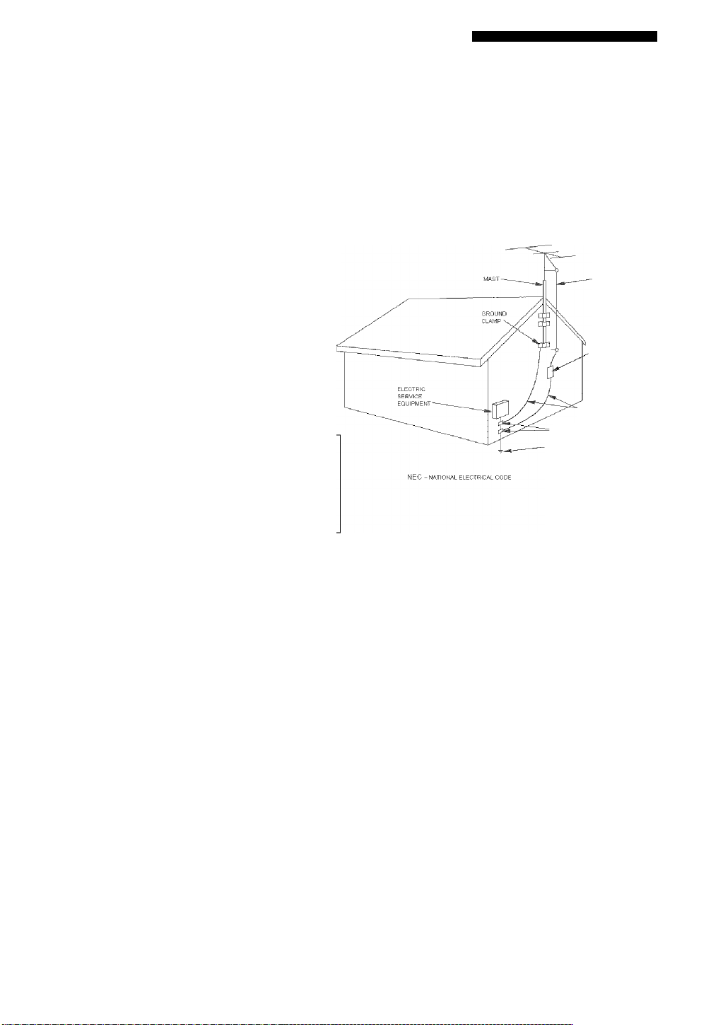
24 Outdoor Antenna Grounding — If an outside antenna or
cable system is connected to the product, be sure the antenna
or cable system is grounded so as to provide some
protection against voltage surges and built-up static charges.
Article 810 of the National Electrical Code, ANSI.'NFPA 70.
provides information with regard to proper grounding of the
mast and supporting structure, grounding of the lead-m wire
to an antenna discharge unit, size of grounding conductors,
location of anteima discharge unit, connection to grounding
electrodes, and requirements for the grounding electrode.
EXAMPLE OF ANTENNA GROUNDING
ANTENNA
DISCHARGE UNIT
(NEC SECTION 810-20)
GROUNDING CONDUCTORS
(NEC SECTION 810-21)
- GROUND CLAMPS
PO'AER SERVICE GROUNDING
ELECTRODE SYSTEM
(NEC ART 2M. PART K}
FCC INFORMATION (for US customers)
IMPORTANT NOTICE: DO NOT MODIFA' THIS
UNIT!
This product, when installed as indicated in the
instructions contained in this manual, meets FCC
requirements. Modifieations not expressly approved by
Yamaha may void your authority, granted by' the FCC, to
use the product.
IMPORTANT; WTien connecting this product to
accessories and/or another product use only high quality
shielded cables, Cabie.'s supplied w'lth this product MUST
be used. Follow' all installation instructions. Failure to
follow instructions could void your FCC authorization to
use this product in the USA.
NOTE: This product has been tested and found to comply'
with the requirements listed m FCC Regulations. Part 15
for Class “B” digital devices. Compliance with these
requirements provides a reasonable level of assurance that
your use of this product in a residential environment will
not result in harmful interference with other electronic
devices.
This equipment generates.'uses radio frequencies and, if
not installed and used according to the instractions found
in the users manual, may' cause interference harmful to the
operation of other electronic devices.
Compliance with FCC regulations does not guarantee that
interference will not occur in all installations. If this
product IS found to be the soitrce of interference, wdiich
can be determined by turning the unit “OFF” and “ON”,
please try' to eliminate the problem by using one of the
following measures:
Relocate either this product or the device that is being
affected by the interference.
Utilize power outlets that are on different branch (circuit
breaker or fuse) circuits or install AC line filter/s.
In the case of radio or TV interference, relocate/reorient
the antenna. If the antenna lead-in is 300 ohm ribbon lead,
change the lead-in to coaxial type cable.
If these corrective measures do not produce satisfactory'
results, please contact the local retailer authorized to
distribute this type of product, if you can not locate the
appropriate retailer, please contact Yamaha Electronics
Corp., U.S.A. 6660 Orangethorpe Ave, Buena Park. CA
90620.
The above statements apply ONLY to those products
distributed by Yamaha Corporation of America or its
subsidiaries.
Page 4

CAUTION: READ THIS BEFORE OPERATING YOUR UNIT.
1 To assure the finest performance, please read this
manual carefuily. Keep it in a safe place for future
reference.
2 Install this sound system in a well ventilated, cool,
dry, clean place - away from direct sunlight, heat
sources, vibration, dust, moisture, and/or cold.
Allow ventilation space of at least 30 cm on the top,
20 cm on the left and right, and 20 cm on the back of
this unit.
3 Locate this unit away from other electrical
appliances, motors, or transformers to avoid
humming sounds.
4 Do not expose this unit to sudden temperature
changes from cold to hot, and do not locate this unit
in a environment with high humidity (i.e. a room with
a humidifier) to prevent condensation inside this
unit, which may cause an electrical shock, fire,
damage to this unit, and/or personal injury.
5 Avoid installing this unit where foreign object may
fall onto this unit and/or this unit may be exposed to
liquid dripping or splashing. On the top of this unit,
do not place:
- Other components, as they may cause damage
and/or discoloration on the surface of this unit.
- Burning objects (i.e. candles), as they may cause
fire, damage to this unit, and/or personal injury.
- Containers with liquid in them, as they may fall
and liquid may cause electrical shock to the user
and/or damage to this unit.
6 Do not cover this unit with a newspaper, tablecloth,
curtain, etc. in order not to obstruct heat radiation. If
the temperature inside this unit rises, it may cause
fire, damage to this unit, and/or personal injury.
7 Do not plug in this unit to a wall outlet until all
connections are complete.
8 Do not operate this unit upside-down. It may
overheat, possibly causing damage.
9 Do not use force on switches, knobs and/or cords.
10 When disconnecting the power cord from the wall
outlet, grasp the plug; do not pull the cord.
11 Do not clean this unit with chemical solvents; this
might damage the finish. Use a clean, dry cloth.
12 Only voltage specified on this unit must be used.
Using this unit with a higher voltage than specified
is dangerous and may cause fire, damage to this
unit, and/or personal injury. YAMAHA will not be
held responsible for any damage resulting from use
of this unit with a voltage other than specified.
13 To prevent damage by lightning, disconnect the
power cord from the wall outlet during an electrical
storm.
14 Do not attempt to modify or fix this unit. Contact
qualified YAMAHA service personnel when any
service is needed. The cabinet should never be
opened for any reasons.
15 When not planning to use this unit for long periods
of time (i.e. vacation), disconnect the AC power plug
from the wall outlet.
16 Be sure to read the “TROUBLESHOOTING” section
on common operating errors before concluding that
this unit is faulty.
17 Before moving this unit, press STANDBY/ON to set
this unit in the standby mode, and disconnect the
AC power plug from the wall outlet.
WARNING
TO REDUC’E THE RISK OF FIRE OR ELECTRIC
SHOC'K, DO NOT EXPOSE THIS UNIT TO RAIN
OR MOISTURE.
This unit is not disconnected from the AC power
source as long as it is connected to the wall outlet,
even if this unit itself is turned off This state is called
the standby mode. In this state, this unit is designed to
consume a veiy small quantity of power.
IMPORTANT
Please record the serial number of this unit in the space
below.
MODEL:
Serial No.:
The serial number is located on the rear of the unit.
Retain this Owner’s Manual in a safe place for future
reference.
We Want You Listening For A Lifetime
YAMAHA and the Electronic Industries Association’s Consumer Since lieanna damaae from loud sounds is often
Electronics Group want you to get the most out of your
equipment by playing it at a safe level. One that lets the sound
eome through loud and clear without annoying blaring or
distortion — and, most importantly, without affecting your
sensitive hearing.
III
undetectable until it is too late, YAMAHA and the
Electronic Industries Association’s Consumer
Electronics Group recommend you to avoid
prolonged exposure from excessive volume levels.
USTENOfG
ForAl^fnnm.-
-
Page 5

CONTENTS
[ EATURES
GETTING STARTED
Supplied accessories
Installing batteries in the remote control
CONTROLS AND FUNCTIONS
Front panel................................................................4
Remote control.........................................................6
Using the remote control..........................................7
Front panel display...................................................8
Rear panel...............................................................10
SPEAKER SETUP...................................................11
Speaker placement.................................................11
Speaker connections...............................................12
CONNECTIONS
Before connecting components
Connecting video components
Connecting audio components
Connecting the FM and AM antennas
Connecting the power supply cord.........................20
Turning on the power.............................................20
BASIC SETUP..........................................................21
Using the bask: SETUP menu
PLAYBACK..............................................................24
Basic operations
Selecting soLind field programs
Selecting input modes
FM/AM LI NING
Automatic and manual tuning
Presetting stations
Selecting preset stations
Exchanging preset stations
XM SATEILLITE RADIO TUNING.....................38
Wliat is XM Satellite Radio‘d................................38
XM Satellite Radio connections.............................38
XM Satellite Radio functions.................................38
Activating XM Satellite Radio
Basic XM Satellite Radio operations
XM Satellite Radio search modes..........................41
Setting XM Satellite Radio preset ehamiels...........44
RECORDING
................................................................
...............................................
...............................................
.................
.............................
......................................................
..............................
...............................
...............................
...................
..............................
.....................................................
............................
............................................
.....................................................
................................
..................................................
.........................................
.....................................
...............................
.....................
...........................................................
14
14
15
18
19
21
24
26
30
32
32
33
35
36
39
40
47
SOUND FIELD PROGRAMS
2
3
3
3
4
SOUND FIELD PROGRAM
DESCRIPTIONS..................................................48
For movie/video sources
For music sources...................................................50
ADVANCED OPERATIONS..................................51
EUmg the sleep timer
Manually adjusting speaker levels
SET MENU...............................................................53
Using SET MENU..................................................54
1 SOUND MENU..................................................55
2 INPUT MENU
3 OPTION MENU
REMOTE CONTROL FEATURES.......................60
Control area............................................................60
Setting remote control codes
Controlling other components................................62
........................................
.............................................
.........................
....................................................
.................................................
.................................
61
48
5!
52
57
58
ADDITIONAL INFORMATION
EDITING SOUND FIELD PARAMETERS
W'Tiat IS a soitnd field
Changing parameter settings
SOItND FIELD PARAMETER
DESCRIPTIONS..................................................65
TROUBLESHOOTING...........................................67
RESETTING THE FACTORY PRESETS
GLOSSARY..............................................................72
Audio fonnats.........................................................72
Sound field programs.............................................73
Audio information..................................................73
Video signal information........................................74
SPECIFICATIONS..................................................75
...............................................
..................................
.........
...........
63
63
63
71
Page 6

FEATURES
Built-in 6-channel power amplifier
♦ Minimum RMS output power
(0,9% THD, 1 kHz, 6 Q)
Front: 120 W+ 120 W
Center: 120 W
Surround: 120 W + 120 W
Subwoofer: 120 W (30 Hz, 6 O)
Sound field features
♦ Proprietary YAMAHA technology for the creation of
sound fields
♦ Dolby Digital decoder
♦ DTS, DTS Neo: 6, DTS 96/24 decoder
♦ Dolby Pro Logic.'Dolby Pro Logic II decoder
♦ Virtual CINEMA DSP
♦ SILENT CINEMA™
Sophisticated AM/FM tuner
♦ 40-station random and direct preset tuning
♦ Automatic preset tuning
♦ Preset station shifting capability (preset editing)
XM Satellite Radio
♦ XM Satellite Radio programming (using the “XM
Connect and Play digital antenna”, sold seperately)
Other features
♦ 192-kHz/24-bit D/A converter
♦ A SET MENU that provides you with items for
optimizing this unit for your audio,'Video system
♦ 6 additional input jacks for discrete multi-channel input
♦ Component video input-output eapability
♦ Optical and coaxial digital audio signal jacks
♦ Sleep timer
♦ Cinema and music night listening modes
♦ Remote control with preset remote control codes
y indicates a tip for your operation.
Some operations can be performed by using either the buttons on the main unit or on the remote control. In cases when the button
names differ between the main unit and the remote control, the button name on the remote control is given in parentheses.
This manual is printed prior to production. Design and specifications are subject to change in part as a result of improvements, etc. In
case of differences between the manual and product, the product has priority.
□arsali^
DIGITAL
Manufactured under license from Dolby Laboratories.
“Dolby”, “Pro Logic” and the doub!e-D symbol are trademarks of
Dolby Laboratories.
SILENT ~
CINEMA
“SILENT CINEMA" is a trademark of YAMAHA
CORPORATION.
PTWI
“DTS”, “Neo:6” and “DTS 96/24” are registered trademarks of
Dicital Theater Systems, Inc.
READY
The XM name and related logos are registered trademarks of XM
Satellite Radio Inc.
Page 7
GETTING STARTED
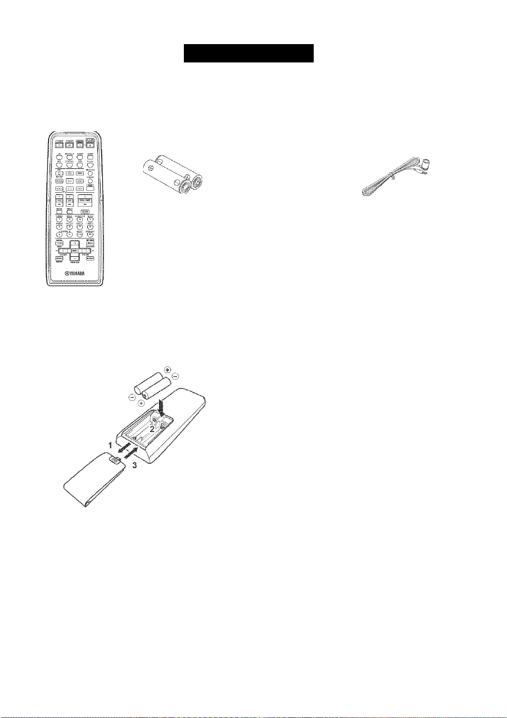
Supplied accessories
Please check that you received all of the following parts.
Remote control
Batteries (2)
(AA, R06, UM-3)
Instaiiing batteries in the remote control
AM loop antenna
indoor FM antenna
Notes on batteries
• Change all of the batteries if you notice the following
conditions; the operation range of the remote control decreases,
the indicator does not flash or its light becomes dim.
• Do not use old batteries together with new ones.
• Do not use different types of batteries (sueh as alkaline and
manganese batteries) together. Read the packaging careftilly as
these different types of batteries may have the same shape and
color.
• If the batteries have leaked, dispose of them immediately. Avoid
touching the leaked material or letting it come into contact with
clothing, etc. Clean the battery' compartment thoroughly before
installing new batteries.
• Do not throw away batteries with general house tvaste; dispose
of them correctly in accordance with vour local résiliations.
1 Press the w part and slide the battery
compartment cover off.
2 Insert two supplied batteries (AA, R06,
UM-3) according to the polarity markings
(+ / -) on the inside of the battery
compartment.
3 Slide the cover back until it snaps into place.
If the remote eontrol is without batteries for more than
2 minutes, or if exhausted batteries remain in the
remote control, the contents of the memory may be
cleared. When the memory is cleared, insert new;
batteries, set up the remote control code and program
any acquired functions that may have been cleared.
Page 8
Front panel
CONTROLS AND FUNCTIONS
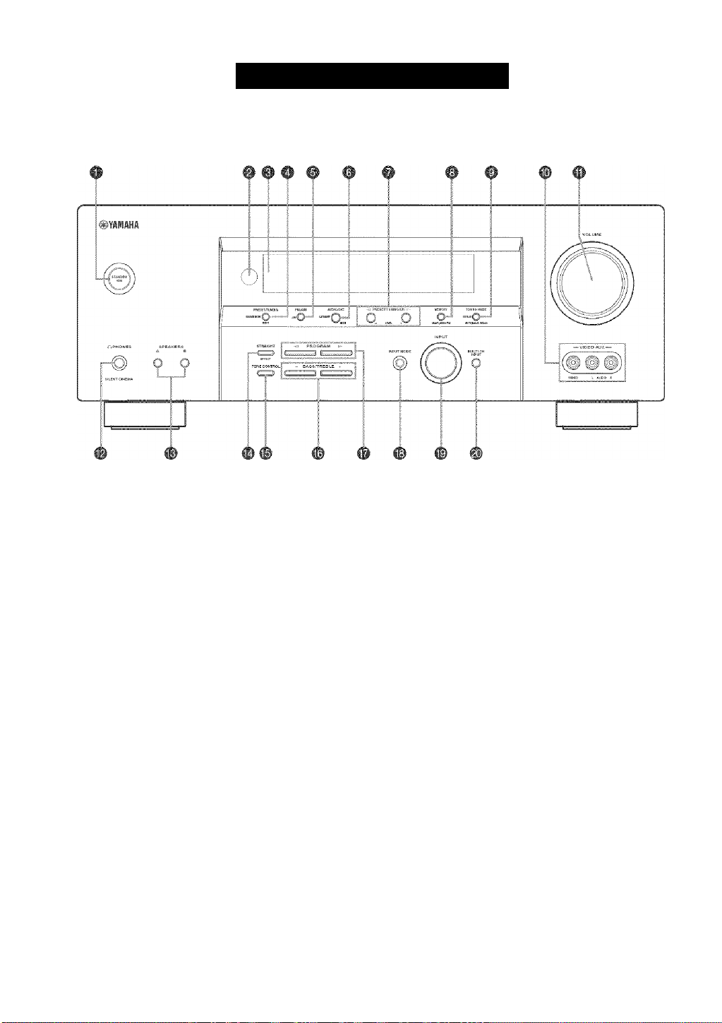
1
STANDBY/ON
Turns on this unit or sets it to the standby mode. When
you turn on this unit, you will hear a click and there will
be a 4 to 5-second delay before this unit can reproduce
sound.
Note
In standby mode, this unit consumes a small amount of power in
order to receive infrared-signals from the remote control.
2 Remote control sensor
Receives signals from the remote control.
3 Front panel display
Shows information about the operational status of this unit.
4
PRESET/TUNING (EDIT), SEARCH MODE*
Switches the function of PRESET/TUNING/CH I / h,
LEVEL between selecting preset station numbers and
tuning.
5 FM/AM, XM*
Stvitches the reception band when the unit is in tuner
mode.
6 A/B/C/D/E, NEXT, CATEGORY*
Selects one of the 5 preset station groups (A to E) wdien
the unit is 111 tuner mode.
Selects the speaker channel to be adjusted wdien the unit is
not in tuner mode.
7
PRESET/TUNING/CH* I / h, LEVEL-/+
Selects preset station number I to 8 when the colon (:) is
displayed next to the band indication in the front panel
display w'hen the unit is in tuner mode. Selects the tuning
frequency when the colon (:) is not displayed.
Adjusts the level of the speaker channel selected using
\ H t A I (NEXT) when the unit is not in tuner mode.
8 MEMORY (MAN’L/AUTO FM)
Stores a station in the memory. Elold down this button for
more than 3 seconds to start automatic preset tuning.
9 TUNING MODE (AUTO/MAN’L MONO),
DISPLAY’
Switches betw'een automatic tuning (AEJTO indicator on)
and manual tuning (AUTO indicator off).
Page 9

0 VIDEO AUX jacks
Input audio and video signals from a portable external
source such as a game console. To reproduce source
signals from these jacks, select V-AUX as the input source.
A
VOLUME
Controls the output level of all audio channels.
This does not affect the REC OUT level.
B
n PHONES {SILENT CINEMA) jack
Outputs audio signals for private listening with
headphones. When you connect headphones, no signals
are output to the OUTPUT jacks or to the speakers.
All Dolby Digital and DTS audio signals are mixed down
to the left and right headphone channels.
C
SPEAKERS A/B
Turns on or off the set of front speakers connected to the A
and/or B teniiinals on the rear panel each time the
corresponding button is pressed.
D
STRAIGHT (EFFECT)
Switches the sound fields off or on. When STRAIGHT is
selected, input signals (2-channel or multi-channel) are
output directly from their respective speakers without
effect processing.
E
TONE CONTROL
Use to adjust the bass/'treble balance for the front left and
right speakers (see page 25).
F
BASS/TREBLE-/+
Use to adjust the bass/treble balance for the front left and
right speakers (in conjunction with TONE CONTROL).
CONTROLS AND FUNCTIONS
G
PROGRAM I / h
Use to select sound field programs (see page 25).
H
INPUT MODE
Sets the priority (AUTO, DTS, ANALOG) for the type of
signals received when one component is connected to two
or more of this unit’s input jacks (see page 30).
1 INPUT selector
Selects the input source you want to listen to or watch.
J
MULTI CH INPUT
Selects the source connected to the MULTI CH INPUT
jacks. When selected, the MULTI CH INPUT source takes
priority over the source selected with INPUT (or the input
selector buttons on the remote control).
Available only when the unit is in the XM Satellite Radio
mode (see page 39).
Page 10
CONTROLS AND FUNCTIONS
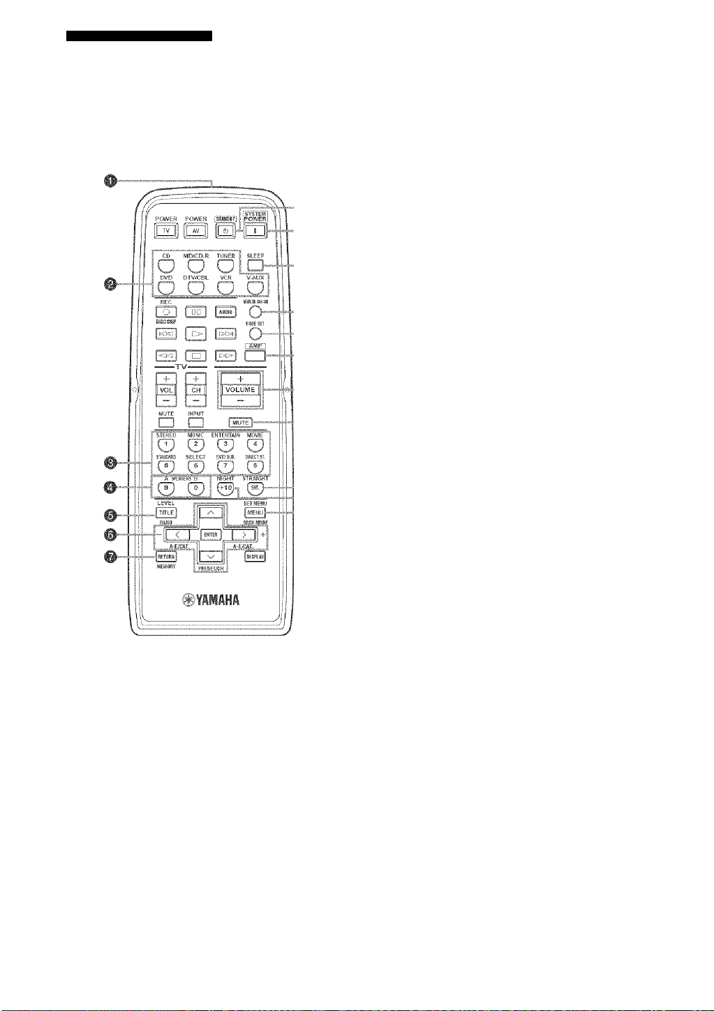
Remote control
This section describes the function of each control on the
remote control used to control this unit. To operate other
components, see “REMOTE C'ONTROL FEATURES" on
page 60.
#
#
1
Infrared window
Outputs infrared control signals. Aim this window at the
component you want to operate.
2 Input selector buttons
Select the input source and change the control area.
3 Sound field program/numeric buttons
Use to select sound field programs.
Use numbers I through 8 to select preset stations when the
unit is in tuner mode.
Use SELECT to playback 2-channel sources in surround
(see page 28).
Use EXTD SUR. to turn on/off the extended surround
modes (see page 27).
Use DIRECT ST. to playback 2-channel sources in high
fidelity sound (see page 29).
4. SPEAKERS A/B
Use to turn on or off the set of front speakers connected to
the A and, or B terminals on the rear panel each time the
corresponding button is pressed.
5 LEVEL, BAND
Selects the speaker channel to be adjusted and sets the
level.
Switches the reeeption band when the unit is in tuner
mode.
6 Cursor buttons u / d / j / i /ENTER
Use to select and adjust sound field program parameters or
SET MENU items.
Press j i to select a preset station group (A to E) w'hen
the unit is in tuner mode.
Press u d to select a preset station number (I to 8)
w'hen the unit is in tuner mode.
7
RETURN, MEMORY*
Returns to the previous menu level when adjusting the
SET MENU parameters.
8 STANDBY
Sets this unit ill the standby mode.
8 SYSTEM POWER
Turns on the pow'er of this unit.
O SLEEP
Sets the sleep timer.
A
MULTI CH IN
Selects multi-channel input when using an external
decoder (etc.).
B
CODE SET
Use to set up remote control codes (see page 61).
Page 11
C
AMP
Selects the AMP mode. You must select the AMP mode to
control the main unit.
D
VOLUME+/-
Increases or decreases the volume level.
E
MUTE
Mutes the sound. Press again to restore the audio output to
the previous volume level.
F
STRAIGHT, ENT.*
Switches the sound fields off or on. When STRAIGHT is
selected, input signals (2-channel or multi-channel) are
output directly from their respective speakers without
effect processing.
G
NIGHT
Turns on or off the night listening modes (see page 29).
H
SET MENU, SRCH MODE*
Activates the SET MENU function.
CONTROLS AND FUNCTIONS
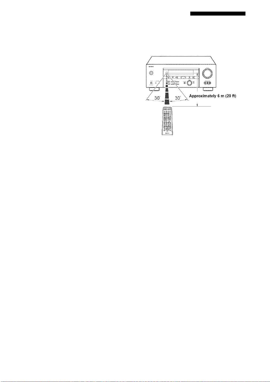
Using the remote control
The remote control transmits a directional infrared beam.
Be sure to aim the remote control directly at the remote
control sensor on the main unit during operation.
Available only when the unit is in the XM Satellite Radio
mode (see page 39),
Handling the remote control
Do not spill water or other liquids on the remote
control.
Do not drop the remote control.
Do not leave or store the remote control in the
following types of conditions:
- places of high humidity, such as near a bath
- high temperature, such as near a heater or stove
- extremely low temperatures
- dusty places
Page 12

CONTROLS AND FUNCTIONS
Front panel display
dts
■MATRIX
'I □□ DIGITALI
.□□PL
VIRTUAL SILEWTCIWEHA
STAUDARD
VCR
□ □□□□ □□□□□ Î □□□□□«□□□□□ I □□□□□ □□□□□ □□□□□ s □□□□□ □□□□□ □□□□□ □□□□□ □□□□□ □□□□□ □□□□□? #t
□ □□□□ □□□□□ □□□□□ □□□□□ □□□□□ □□□□□ □□□□□ □□□□□? ®
□ □□□□ □□□□□f □□□□□ i □□□□□ } □□□□□ □□□□□ □□□□□ a □□□□□ □□□□□ □□□□□ □□□□□ □□□□□ □□□□□ □□□□□«
V-AUX DTV/CBL DVD ftSD/CD-R TUNER CD
EÎIQHÎ
b
1 Decoder indicators
When any of this unit’s decoders function, the respective
indicator lights up.
2
VIRTUAL indicator
Lights up when Virtual CINEMA DSP is active (see
page 30).
3 SILENT CINEMA indicator
Lights up when headphones are connected and a sound
field program is selected (see page 25).
4
Input source indicators
A cursor lights to show the current input source.
5 Sound field indicators
Light to indicate the active DSP sound fields.
Presence DSP sound field
/L L\ ' Listening position
Left siirroimd Right surround
DSP sound field ; DSP sound field
,'■..■ n-
Snrround back DSP sound field
6 CINEMA DSP indicator
Lights up when you select a CINEMA DSP sound field
program.
^ AUTO indicator
Lights up to indicate that automatic tuning is possible.
S
TUNED indicator
Lights up when this unit is tuned into a station.
9 STEREO indicator
Lights up when this unit is receiving a strong signal for an
FM stereo broadcast while the AUTO indicator is lit.
AUTO TUMED STEREO iVIEHORY MUTE VOLUME
HiFi DSP
mS ■
dB
■= = cIB
iLFE
0 MEMORY indicator
Flashes to show that a station can be stored.
A
MUTE indicator
Flashes while the MUTE lunctioii is on.
B VOLUME level indication
Indicates the current volume level.
C PCM indicator
Lights up when this unit is reproducing PCM (Pulse Code
Modulation) digital audio signals.
D
STANDARD indicator
Lights up when Surround Standard or Sun'ound Enhanced
is selected (see page 28).
E
NIGHT indicator
Lights up when you select night listening mode.
F SP A B indicators
Light up according to the set of front speakers selected.
Both indicators light up when both sets of speakers are
selected.
G
Headphones indicator
Lights up when headphones are connected.
H
HiFi DSP indicator
Lights up when you select a HiFi DSP sound field
program.
1 Multi-information display
Shows the current sound field program name and other
information when adjusting or changing settings.
J SLEEP indicator
Lights up while the sleep timer is on.
c 'r;
'SR'
Page 13

K 96/24 indicator
Lights up when a DTS 96 24 signal is input to this unit.
L. LFE indicator
Lights up when the input signal contains the LFE signal.
M Input channel indicators/speaker indicators
Indicate the channel components of the cun'ent digital
input signal.
Indicate the number of speakers connected in SPEAKERS
(page 22), or indicate the channel being adjusted in
SP LEVEE (page 55).
CONTROLS AND FUNCTIONS
Page 14
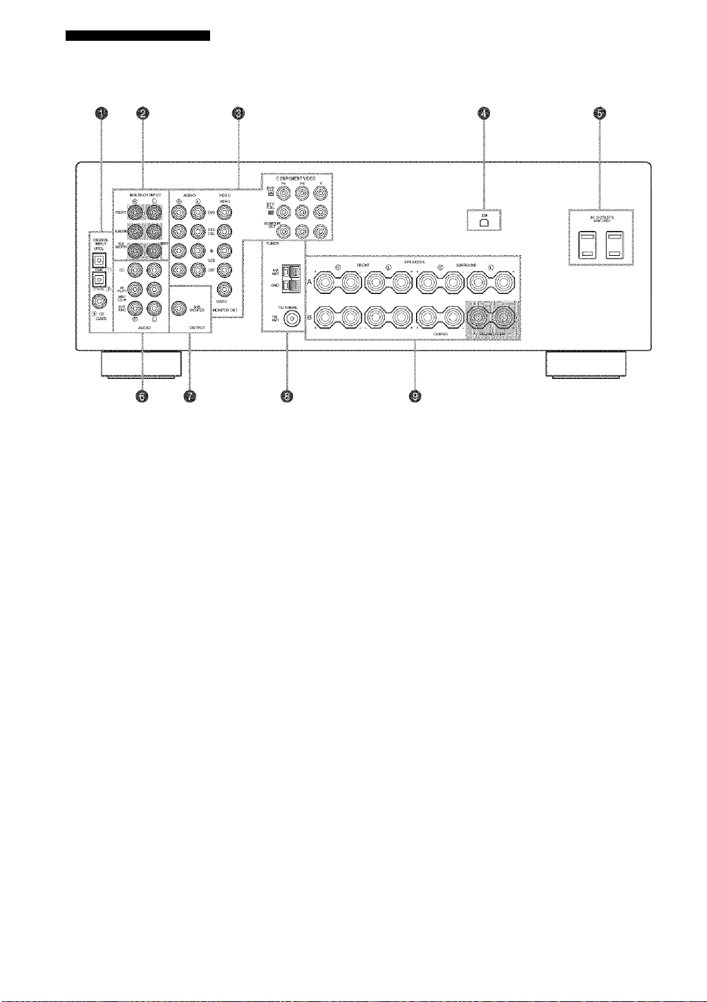
CONTROLS AND FUNCTIONS
Rear panel
1
DIGITAL INPUT jacks
Seepages 15, 17 and 18 for details.
2
MULTI CH INPUT jacks
See page 16 for connection information.
3 Video component jacks
See pages 15 and 17 for connection information.
4
XMjack
See page 39 for connection information.
5 ACOUTLET(S)
Use to supply power to your other A/V eomponents
(see page 20).
6 Audio component jacks
See page 18 for eonnection information.
7
SUBWOOFER OUTPUT jack
See page 13 for eonnection information.
S Antenna terminals
See page 19 for eonnection information.
9
Speaker terminals
See page 13 for eonnection information.
10
Page 15
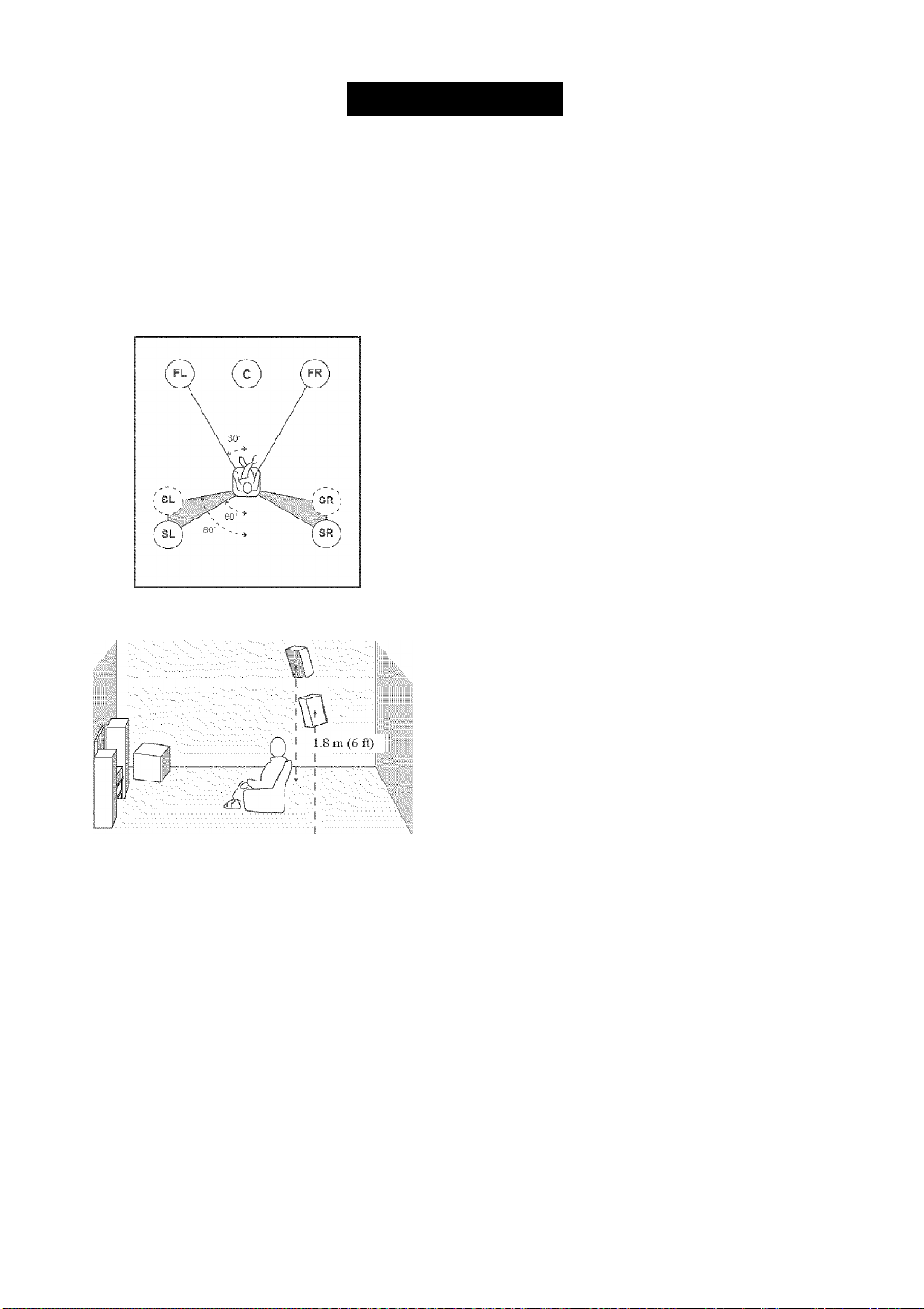
SPEAKER SETUP
Speaker placement
The speaker layout below shows the standard ITTI-R*
speaker setting. You can use it to enjoy CINEMA DSP
and multi-channel audio sources.
* ITU-R IS the radio communication sector of the ITU
(International Telecoimuuiication Union).
Surround speakers (SR and SL)
The surround speakers are used for effect and surround
sounds. Place these speakers behind your listening
position, facing slightly inwards, about 1.8 m (6 ft) above
the floor.
Subwoofer
The use of a subwoofer, such as the YAMAHA Active
Serv'o Processing Subwoofer System, is effective not only
for reinforcing bass freciuencies from any or all channels,
but also for high fidelity reproduction of the LEE (lowfrequency effect) channel included in Dolby Digital and
DTS software. The position of the subwoofer is not so
critical, because lotv bass sounds are not highly
directional. But it is better to place the subwoofer near the
front speakers. Turn it slightly tow'ard the center of the
room to reduce wall reflections.
Front speakers (FR and FL)
The front speakers are used for the main source sound plus
effect sounds. Place these speakers an equal distance from
the ideal listening position. The distance of each speaker
from each side of the video monitor should be the same.
Center speaker (C)
The center speaker is for the center channel sounds
(dialog, vocals, etc.). If for some reason it is not practical
to use a center speaker, you can do without it. Best results,
however, are obtained wnth the full system. Align the front
face of the center speaker with the front face of your video
monitor. Place the speaker centrally betw'een the front
speakers and as close to the monitor as possible, such as
directly over or under it.
11
Page 16
SPEAKER SETUP
Speaker connections
Be sure to connect the left channel (L), right channel (R),
“+” (red) and (black) properly. If the connections are
faulty, no sound will be heard from the speakers, and if the
polarity of the speaker connections is incorrect, the sound
will be unnatural and lack bass.
CAUTION
• Before connecting the speakers, make sure that the
power of this unit is off.
• Do not let the bare speaker wires touch each other or
do not let them touch any metal part of this unit. This
could damage this unit and/or speakers.
• Use magnetically shielded speakers. If this type of
speakers still creates the interference with the monitor,
place the speakers away from the monitor.
A speaker cord is actually a pair of insulated cables
running side by side. One cable is colored or shaped
differently, perhaps ivith a stripe, groove or ridges.
Connect the striped (grooved, etc.) cable to the “+” (red)
temiinals on this unit and your speaker. Connect the plain
cable to the (black) terminals.
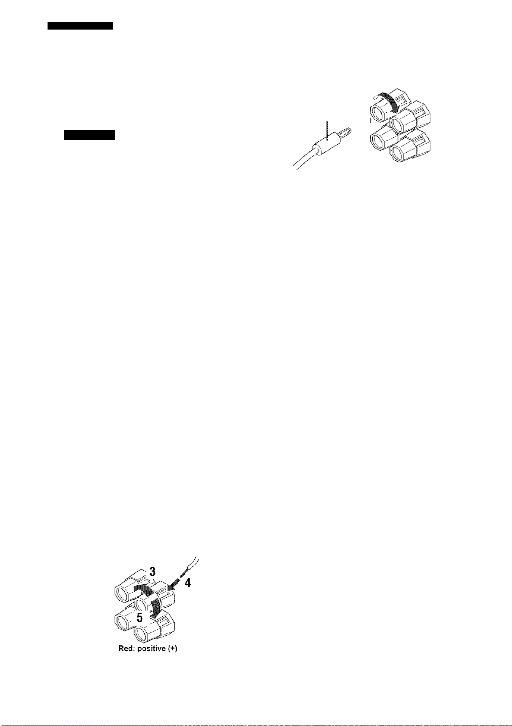
■ Banana plug connections
First, tighten the knob and then insert the banana plug
connector into the end of the corresponding terminal.
Banana plug
10 mm (3/8"
1 Remove approximately 10 mm {3/8") of
insulation from the end of each speaker
cable.
2 Twist the exposed wires of the cable together
to prevent short circuits.
3 Unscrew the knob. 4 Insert one bare wire into the hole in the side
of each terminal.
5 Tighten the knob to secure the wire.
12
Black: negative (-)
Page 17
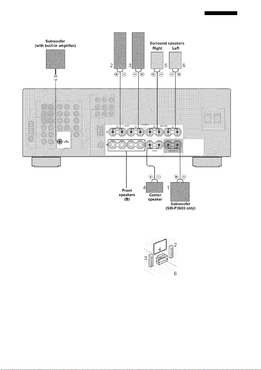
Front speakers fA)
Right Left
SPEAKER SETUP
■ FRONT terminals
Connect one or two speaker systems (2, 3) to these
terminals. If you use only one speaker system, connect it
to the FRONT A or B terminals.
■ CENTER terminals
Connect a center speaker (4) to these terminals.
■ SURROUND terminals
Connect surround speakers (5, 6) to these terminals.
■ SUBWOOFER terminals
Connect the YAMAHA SW-P3600 subwoofer to these
terminals.
■ SUBWOOFER jack
Connect a subw'oofer wdth built-in amplifier, such as the
YAMAHA Active Servo Processing Subwoofer System,
to this jack w'hen you do not use the YAMAHA SWP3600 subwoofer.
Speaker layout
13
Page 18
CONNECTIONS
Before connecting components
CAUTION
Do not connect this unit or other components to the mains
power until all connections bet\¥een components are
complete.
■ Cable indications
Dust protection cap
Pull out the eap from the optical jack before you connect
the fiber optic cable. Do not discard the cap. When you are
not using the optical jack, be sure to put the cap back in
place. This cap protects the jack from dust.
For analog signals
left analog ca.bles
right analog cables
For digital signals
optical cables
coaxial ca.bles
For video signals
video cables
component video cables
■ Analog jacks
You can input analog signals from audio components by
connecting audio pin cable to the analog jacks on this unit.
Connect red plugs to the right jacks and white plugs to the
left jacks.
■ Digital jacks
This unit has digital jacks for direct transmission of digital
signals through either coaxial or fiber optic cables. You
can use the digital jacks to input PCM, Dolby Digital and
DTS bitstreams. When you connect components to both
the COAXIAL and OPTICAL jacks, priority is given to
the input signals from the COAXIAL jack. All digital
input jacks are compatible rvith 96-kHz sampling digital
signals.
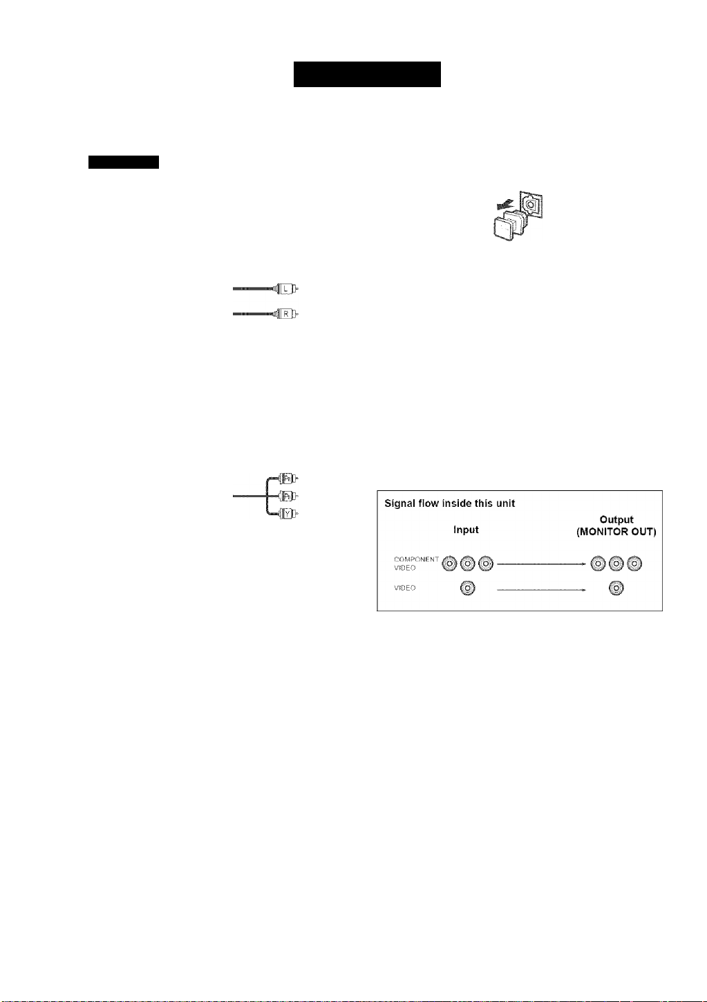
■ Video jacks
This unit has ttvo types of video jacks. Connection
depends on the availability of input jacks on your monitor.
VIDEO
VIDEO jacks
For conventional composite video signals.
COMPONENT VIDEO jacks
For component signals, separated into luminance (Y) and
color difference (Pb, Pr) to provide the best quality in
picture reproduction.
COyPONEMT VIDEO
Note
This unit handles digital and analog signals independently. Thus
audio signals input to the analog jacks are only output to the
analog OUT (REC) jacks.
14
Page 19

CONNECTIONS
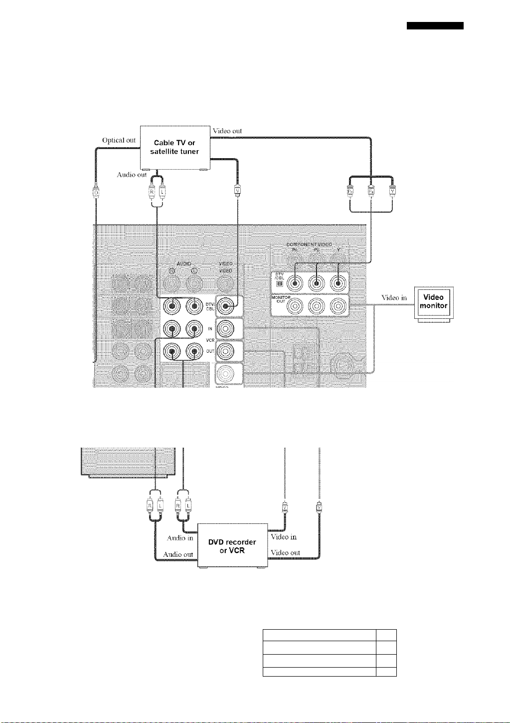
Connecting video components
■ Connections for DVD playback
Note
Be sure to connect your video source components in the same way you connect your video monitor to this unit. For example, if you
connect your video monitor to this unit using a VIDEO connection, connect your video source components to this unit using the VIDEO
connections.
15
Page 20
CONNECTIONS
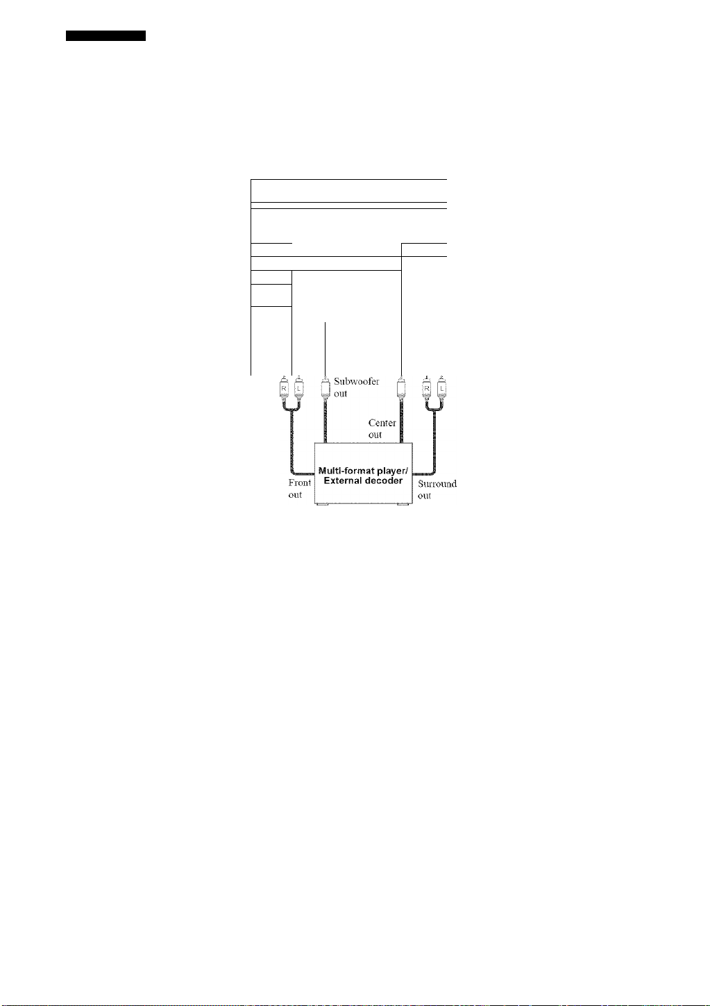
m
Connecting to the MULTI CH INPUT jacks
This unit is equipped with 6 additional input jacks (left and right FRONT, CENTER, left and right SURROUND and
SUBWOOFER) for discrete multi-channel input from a multi-format player, external decoder, sound processor or pre
amplifier.
Connect the output jacks on your multi-format player or external decoder to the MULTI CEI INPUT jacks. Be sure to
match the left and right outputs to the left and right input jacks for the front and surround channels.
" 1 , I Uif-I r
1
lURR
“ :* ...>>•* M M i.l *i
..
-T--
wl
r
Notes
• WTieu you select MULTI CH INPUT as the input source, this unit automatically turns off the digital sound field processor, and you
cannot select sound field programs.
• This unit does not redirect signals input to the MULTI CH INPUT jacks to accommodate for missing speakers. We recommend that
you connect at least a 5.1-cliannel speaker system before using this feaUire.
• WTien headphones are vised, only front left and right channels are output.
16
Page 21
CONNECTIONS
■ Connections for other video components
Note
Be sure to connect your video source components in the same way you connect your video monitor to this unit. For example, if you
connect your video monitor to this unit using a VIDEO connection, connect your video source components to this unit using the VIDEO
connections.
■ ViDEO AUX jacks (on the front panei)
Use these jacks to connect any video source, such as a
game console or video camera, to this unit.
fl I- "=|
1 1 Audio out R
1 Audio out L
Game
console or
video camera
Video out
17
Page 22
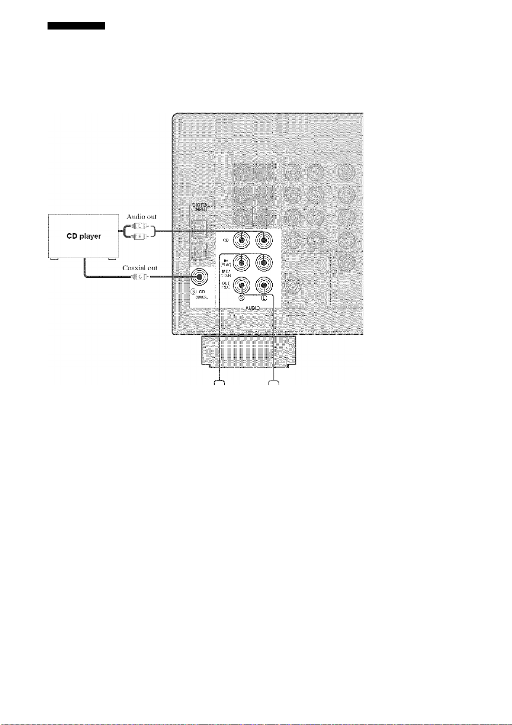
CONNECTIONS
Connecting audio components
I Connections for audio components
,FJ |-j L
Audio out I_I I_I Audio m
MD recorder or
tape deck
18
Page 23
CONNECTIONS
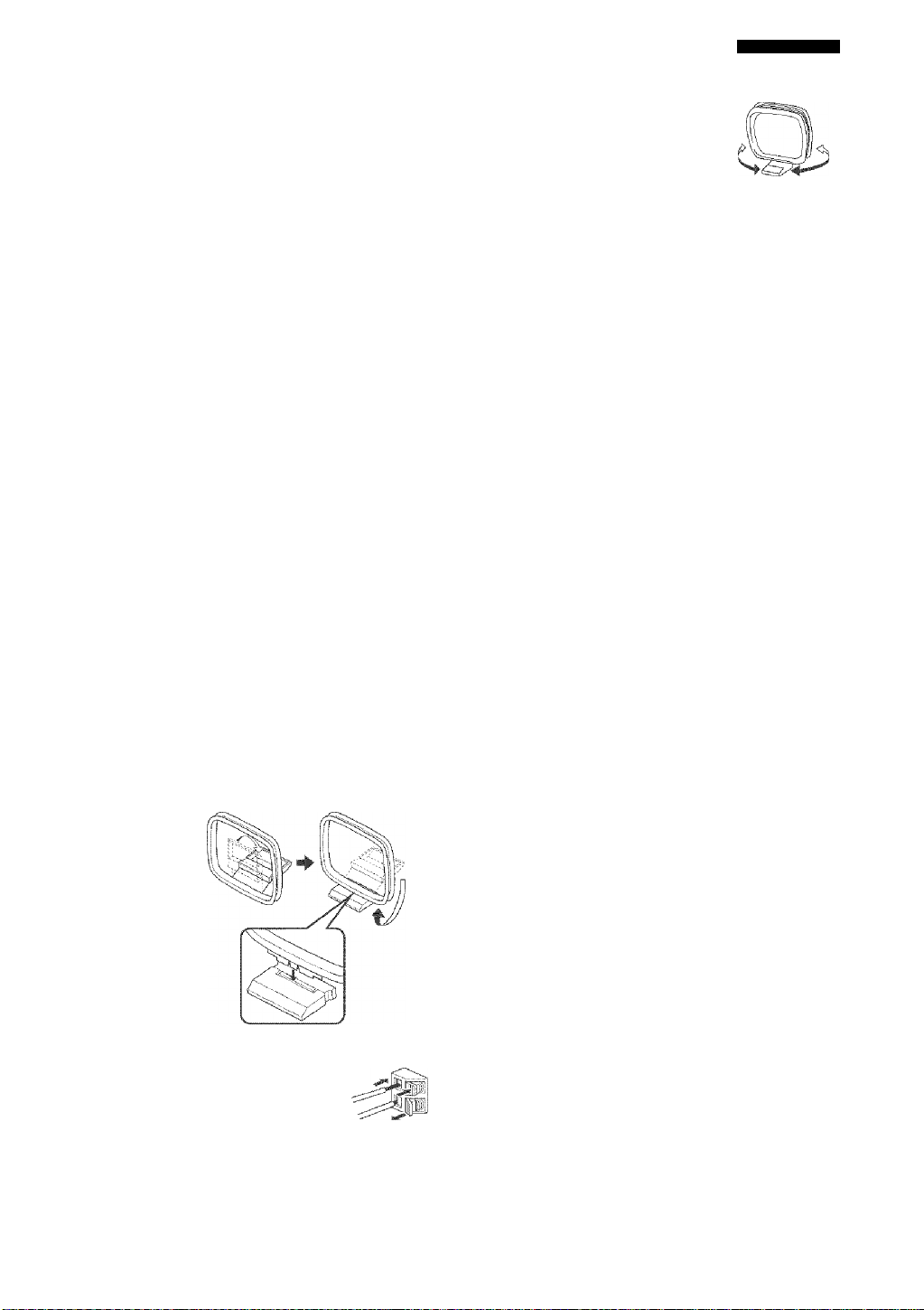
Connecting the FM and AM antennas
Both FM and AM indoor antennas are included with this
unit. In general, these antennas should provide sufficient
signal strength. Connect each antenna correctly to the
designated terminals.
AM loop antenna
(included)
jl
_____
Ground (GND terminal)
For maximum safety and mmiimim interference,
B
connect the antenna GND tennmal to a good eartli
fliround. A good earth ground is a metal stake driven
into moist earth.
Indoor FM antenna
(included)
jl
Orient the AM loop antenna for the best reception.
Nàtés
• The AM loop antenna should be placed away from this unit.
• The AM loop antenna should always be connected, even if an
outdoor AM antenna is connected to this unit.
• A properly installed outdoor antenna provides clearer reception
than an indoor one. If you experience poor reception quality, an
outdoor antenna may improve the quality. Consult the nearest
authorized YAMAHA dealer or senuce center about outdoor
antennas.
■ Connecting the AM loop antenna
1 Set up the AM loop antenna, then connect it
to the terminals on this unit.
ÌV:
I
2 Press and hold the tab to insert
the AM loop antenna lead wires
into the AM ANT and GND
terminals.
19
Page 24
CONNECTIONS
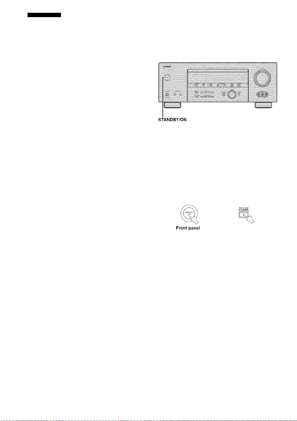
Connecting the power supply cord Turning on the power
■ Connecting the AC power cord
Plug the power eord into an AC wall outlet.
■ AC OUTLET(S) (SWITCHED)
...........
2 outlets
Use these outlets to connect the powder cords from your
other components to this unit. Power to the AC
OUTLET(S) is controlled by this unit’s STANDBY 'ON
(or SYSTEM POWER and STANDBY). The outlet(s)
supply power to any connected component tvhenever this
unit is turned on. The maximum pow-er (total pow-er
consumption of components) that can be connected to the
AC OUTLET(S) IS 100 W.
■ Memory back-up
The memory back-up circuit prevents the stored data from
being lost even if this unit is in the standby mode.
However if the pow er cord is disconnected from the AC
w'all outlet, or the power supply is cut for more than one
week, the stored data w'ill be lost.
When ail connections are complete, turn on the pow'er of
this unit.
(U.S.A. model)
j -n ...J l_ SYSTEM POWER
. ■ ij
—
Press STANDBY/ON (or SYSTEM POWER on the remote control) to turn on the power of this unit.
Remote control
20
Page 25

BASIC SETUP
The basic setup feature is a useful way to set up your
system quickly and with minimal effort.
y
• If you wish to configure the unit manually using more precise
adjustments, use the detailed parameters in SOUND MENU
(page 55) instead of using BASIC SETUP.
• Altering any parameters in BASIC SETUP will reset all
parameters in SOLTSD MENU.
• Initial settings are indicated in bold for each parameter.
Using the BASIC SETUP menu
Press ENTER to enter BASIC SETUP.
The ROOM parameter appears in the front panel
drsplay.
Before you begin:
• Press SPEAKERS A or B on the front panel (or press
AMP to select the AMP mode, then press SPEAKERS
A or B on the remote control) to select the front
speakers you want to use.
• Make sure you disconnect your headphones trom this
unit.
Till
iiBT
Ej[g[:r
mm
1 Press AMP.
( AMP j
2 Press SET MENU.
“BASIC SETUP” appears in the front panel display.
.g
■343
4 Press j / i to select the desired setting.
ROOM: S M >L
Select the size of the room you have installed your
speakers in. In general, the room sizes are defined as
follows:
[U.S.A. and Canada models]
S (small) 16 X 13ft, 200ft2 (4.8 x 4.0m, 20m2)
M (medium) 20 x 16ft, 300ft2 (6.3 x 5.0m, 30m2)
L (large) 26 x 19ft, 450ft2 (7.9 x 5.8m, 45m2)
[Other models]
S (small) 3.6 X 2.8m, 10m2
M (medium) 4.8 x 4.0m, 20m2
L (large) 6.3 x 5.0m, 30m2
5 Press d to display the SUBWOOFER
parameter.
SET MEHU
ITmem
8RCH MODI
BASIC SETUP
6 Press j / i to select the desired setting.
SUBWOOFER--YES
YES If you have a subwoofer in your system.
NONE If vou do not have a subwoofer in vour system.
21
Page 26

BASIC SETUP
7 Press d to display the SPEAKERS
parameter.
8 Press j / i to select the number of speakers
you connected.
SPEAKERS--5spk
Choices Display Speakers
2spk
3spk
4spk
5spk
[U SI
[yic] s
iJL.|
^ :sbI
L C R|
E! ;Sgl
Front L/R
Front L/R, Center
Front L/R, Surround L/R
Front L/R, CenteiT SmToimd L/R
9 Press d to display SET/CANCEL.
11 Press ENTER to confirm your selection.
If you selected SET, you hear a test tone from each
speaker in turn. “CHECK:TestTone” appears in the
trout panel display for a few seconds, then “CHECK:
OK'i’”.
CHECK:TestTone
♦
CHECK OK? YES
12 Press j / i to select the desired setting.
CHECK OK? YES
YES To complete the setup process if the test tone
levels from each speaker were satisfactory.
NO
To proceed to the SP LEVEL speaker level
adjustment menu to balance the level of each
speaker.
13 Press ENTER to confirm your selection.
10 Press j / i to select the desired setting.
>SET CANCEL
SET To apply the settings you chose in steps
4 through 8.
CANCEL To cancel the setup without making
any changes.
22
If you selected NO in step 12, the front speaker level
adjustment display appears in the front panel display.
Page 27

BASIC SETUP
■ To balance the speaker levels
Perfonii the foilowing steps after step 13 (see page 22).
VCR V-AUX DW.iCBL DVD MD.'CD-R TUNER CD
FR
The unit outputs the test tone from the selected speaker
and the left front (or left surround) speaker in turn. The
indicator of the speaker currently outputting the test tone
flashes in the front pane! display.
i I
14 Press d / u to select a speaker, then use j / i
to adjust the balance.
The control range is from +10 dB to -10 dB.
FR
------II------
Adjusts the balance between the front left and right
speakers.
Adjusts the balance between the front left and center
speakers.
SL
------II------
Adjusts the balance between the front left and
surround left speakers.
SR
------II------
Adjusts the balance between the surround left and
surround right speakers.
SWFR-----I I------
Adjusts the balance between the front left speaker
and the subwoofer.
Memory back-up
The memory back-up circuit prevents the stored data
from being lost even if this unit is in the standby mode.
However, if the power cord is disconnected from the
AC outlet, or the power supply is cut for more than one
week, the stored data will be lost. If so, adjust the
items a^ain.
15 Press SET MENU to exit after balancing the
speakers.
23
Page 28

PLAYBACK
Basic operations
(U.S.A. model)
fisa
1 3
7 4
r
ai
3-iiSi
1 Press STANDBY/ON (or SYSTEM POWER on
the remote control) to turn on the power.
m
Ll^
~6
"7
4 Select the input source.
Use INPUT (or press one of the input selector buttons
on the remote control) to select the input you desire.
ri'-
(jifsa
i
Front panel
Remote control
The current input source name and input mode appear
in the front panel display for a few seconds.
VCR V-AUX DTVtCBL OVD , Mtf.'CD-R TUWER CO
JiyiL__Jlllil
Selected input source Input mode
5 Start playback or select a broadcast station
on the source component.
Refer to the operating instructions for the component.
6 Adjust the volume to the desired output level.
VOLUiViE
«I
■ ij
Remote controlFront panel
2 Turn on the video monitor connected to this
unit.
3 Press SPEAKERS A or B (or press AMP to
select the AMP mode, then press SPEAKERS
A or B on the remote control).
Each press turns the respective speakers on or off.
SPEAKERS
A SPEAKERS a
Front panel
Remote control
Front panel
Remote control
24
Page 29

Select a sound field program if desired.
Press PROGRAM I / h repeatedly (or press AMP
to select the AMP mode, then press one of the sound
field program buttons on the remote control) to select
a sound field program. (See page 48 for details about
sound field programs.)
PROGRASVt l:.~
Front panel
PLAYBACK
■ To adjust the tone
You can adjust the tonal quality
of your front left and right
TONE CONTROL
speakers or headphones (when
connected).
Press TONE CONTROL on the
front panel repeatedly to select
TREBLE or BASS, then press
♦
BASSiTREELE +
BASS/TREBLE -/+ repeatedly
to increase or decrease.
• Select TREBLE to adjust the
high frequency response.
• Select BASS to adjust the low frequency response.
y
-spc.ifcr and headphone adjustments are stored independently.
i
Remote control
■ To listen with headphones
(“SILENT CINEMA”)
“SILENT CINEMA” allows you to enjoy multi-channel
music or movie sound, including Dolby Digital and DTS
surround, through ordinaiy headphones. “SIEENT
CINEMA” activates automatically whenever you connect
headphones to the PHONES jack while listening to
CINEMA DSP or HiFi DSP sound field programs. When
activated, the “SILENT CINEMA” indicator lights up in
the front panel display
Notes
• This unit will not be set to “SILENT CINEMA” when MULTI
CH INPUT is selected as the input source.
• “SILENT CINEMA” is not effective when the Direct Stereo or
2ch Stereo program is selected, or in STRAIGHT mode.
Notes
• If> or increase or decrease the high-frequency or low-frequency
sound to an extreme level, the tonal quality of the surround
speakers may not match that of the front left and right speakers.
• TONE CONTROL is not effective with the Direct Stereo
program (page 29) or MULTI CH INPUT.
• When TC- BYPASS is set to AUTO (page 57), and BASS and
TREBLE are set to 0 dB, audio output automatically bypasses
this unit’s tone control circuitry.
■ To mute the sound
Press MLITE on the remote control.
The MUTE indicator flashes m the
front panel display.
To resume the audio output, press
MUTE again (or press VOLUME -,'+).
The MUTE indicator disappears from
the display.
y
You can adjust the muting level (see page 57).
25
Page 30

PLAYBACK
m
Selecting MULTI CH INPUT
Press MULTI CH INPUT (or MULTI CH IN on the
remote control) so that “MULTI CH INPUT” appears in
the front panel display.
Selecting sound field programs
■ Front panel operation
Front panel
Remote control
♦
MULT! CH !NPUT
Note
When “MULTI CH INPUT” is shown m Che front panel display,
no other source can be played. To select another input source with
INPUT (or one of the inpvit selector buttons), press MULTI CH
INPUT (or MULTI CH IN on the remote control) to turn off
“MULTI CH INPUT” in the front panel display.
■ Playing video sources in the
background
You can combine a video image from a video source tvith
sound from an audio source. For example, you can enjoy
listening to classical music while viewing beautiful
scenery from the video source on the video monitor.
Use the input selector buttons on the remote
control to select a video source, then select an
audio source.
Audio sources
^ ^If
..................
fl
- Video sources
'SiSSmSe
^jii vite tj
PROGRAM
Press PROGRAM I / h repeatedly to select the
desired program.
il
'WSm
The name of the selected program appears in the front
panel display.
PROGRAM
UU3
VCR V-AUX DTV./CK. DVD MD/CD-R TUNER CD
Program name
I:-'-
Note
If you want to enjoy audio from the MULTI CH INPUT jacks
together with a video source, first select the video source, then
press MULTI CH INPUT (or MULTI CH IN on the remote
control).
26
Page 31

PLAYBACK
Remote control operation
HiP
I
IB
ill
AMP
Press AMP to select the AMP mode, then press
one of the sound field program buttons
repeatedly to select the desired program.
The name of the selected program appears in the front
panel display.
VCR V-AUX DTV.m UVD_ TUMER CD
Sound field
program
buttons
I 1:1
♦
■ Enjoying multi-channel software
Press AMP on the remote control to select the
AMP mode, then press EXTD SDR. to turn on the
extended surround mode {Auto or Matrix) using
the Matrix technology.
Auto (AUTO)
When the unit recognizes the flag of a 6.1-channel signal,
the unit automatically turns on extended surround mode.
If the unit does not recognize the flag of a 6.1-channel
signal, the extended sun'ound mode turns off.
Matrix (MATRIX)
Plays back multi-channel signals with the extended
surround mode.
Off {OFF)
Plays back any signals without the extended sun'ound
mode.
Program name
y
Feel free to choose a sound field program based on your listening
preference, and not purely on the name of the program itself.
Notes
• When you select an input source, this unit automatically selects
the last sound field program used with that source.
• Sound field programs cannot be selected when MULTI CH
INPUT is selected.
• Sampling frequencies higher than 48 kHz (except for DTS 96/
24 signals) will be sampled down to 48 kHz, then sound field
programs will be applied.
27
Page 32

PLAYBACK
Noiek
• Some 6.1-channel compatible discs do not have the flag of a
6.1-channel signal which this unit can automatically detect. To
enjoy these kinds of discs with the extended surround mode,
select “MATRIX”.
• The extended surround mode is not available in the following
cases:
-When “SUR. LR” (see page 55) is set to NONE.
- When the source coimected to the MULT! CH INPUT jack is
being played.
-When the source being played does not contain surround left
and right channel signals.
-When a Dolby Digital KARAOKE source is being played.
-When “2ch Stereo” or “Direct Stereo” is selected.
-When “AilTO” is selected while using STRAIGHT or one of
the SUR. STANDARD programs.
• WTien the power of this unit is turned off, this setting will be
reset to “AUTO”.
■ Enjoying 2-channel software in surround
Signals input from 2-cliaanel sources can also be played
back on multiple channels.
Press AMP to select the AMP mode, then press
STANDARD on the remote control to switch
between the SUR. STANDARD and SUR.
ENHANCED programs.
When you select the SUR. STANDARD program:
PRO LOGIC
Dolby Pro Logic processing for any sources.
PL I I Movie
Dolby Pro Logic II processing for movie software.
PLII Music
Dolby Pro Logic II processing for music software.
PLII Game
Dolby Pro Logic II processing for game software.
Neo:6 C i nema
DTS processing for movie software.
Neo:6 Mus i c
DTS processing for music software.
When you select the SUR. ENHANCED or MOVIE THEATER program:
PRO LOGIC
Dolby Pro Logic processing for any sources.
PLI I Mov i e
Dolby Pro Logic II processing for movie software.
Neo:6 CInema
DTS processing for movie software.
Or press MOVIE to select the MOVIE THEATER
program.
Press SELECT on the remote control to select
the decoder.
You can select from the follownng modes depending on
the type of software you are playing and your personal
preference.
y
You can also select a decoder by pressing J i on the remote
control when the decoder type is displayed in the front panel
display.
28
Page 33

PLAYBACK
■ Listening to high fideiity stereo sound
(Direct Stereo)
Direct Stereo allows you to bypass this unit’s decoders and
DSP processors to enjoy pure high fidelity sound from 2channel PCM and analog sources.
Press PROGRAM I / h repeatedly (or press
AMP to select the AMP mode, then press DIRECT
ST.) to select “Direct Stereo”.
PROGRAE\it
Front panel
I AMP ■■
Remote control
♦
DIRECT STEREO
Notes
• To avoid unexpected noise, do not play DTS-encoded CDs in
this mode.
• When multi-channel signals (Dolby Digital and DTS) are input,
this unit automatically switches to the corresponding analog
input. (When DTS is selected as an input mode, no sound will
be heard.)
• No sound will be output from the subwoofer.
• TONE CONTROL (page 2.i) and SET MENU (page 53)
settings are not effective.
• The front panel display automatically dims.
• If you press AMP on the remote control to select the AMP
mode, then press DIRECT ST,, the unit automatically enters the
Direct Stereo mode and you cannot toggle between the unit's
other sound field programs.
■ Night listening modes
The night listening modes are designed to improv'e
listenability at lower volumes or at night. Choose either
NIGHTiCINEMA or NIGHTiMUSIC depending on the
type of material you are playing.
Press AMP to select the AMP mode, then press
NIGHT repeatedly on the remote control to select
cinema or music.
Press j / i to adjust the effect level while N!GHT:CINEMA or NIGHTiMUSIC is displayed.
This adjusts the level of compression.
Remote control
Effect.LvI: I D
• Select MIN for minimum compression.
• Select MID for standard compression.
• Select MAX for maximum compression.
y
NIGHT:CINEMA and NIGHT:MUSIC adjustments are stored
independently.
Notes
• You cannot use the night listening modes with the Direct Stereo
program or MULTI CH INPUT (even though the NIGHT
indicator lights up when Direct Stereo is selected).
• The night listening modes may vary in effectiveness depending
on the input source and surround sound settings you use.
■ Downmixing to 2 channels
You can enjoy 2-channel stereo playback ev'en from multi
channel sources.
Press PROGRAM I / h repeatedly {or press
AMP to select the AMP mode, then press
STEREO on the remote control) to select 2ch
Stereo.
PROGRAtuS
Front panel Remote control
When night listening is selected, the NIGHT indicator in
the front panel display lights up.
AMP ) WIGHT
Select NIGHT:CINEMA when watching films to
reduce the dynamic range of film soundtracks and
make dialog easier to hear at lower volumes.
Select NIGHTiMUSIC when listening to music sources
to preserv'e ease-of-listening for all sounds.
Select OFF if you do not want to use this function.
2ch Stereo
y ...
You cat! use a subwoofer with this program when SWTR or
BOTH is selected in '‘BASS OUT'.
29
Page 34

PLAYBACK
■ Listening to unprocessed input signals
In STRAIGHT mode, two channel stereo sources are
output from only the front left and right speakers. Multi
channel sources are decoded straight into the appropriate
channels without any additional effect processing.
Press STRAIGHT (or press AMP to select the
AMP mode, then press STRAIGHT on the remote
control) to select STRAIGHT.
! AMP I STRAIGHT
Selecting input modes
This unit comes with a variety of input jacks. Do the
following to select the type of input signals you want to
use.
1 Rotate INPUT to select the input source.
Front panel
Remote contro!
♦
STRAIGHT
Press STRAIGHT (EFFECT) (or STRAIGHT (ENT.) on
the remote control) again so that “STRAIGHT”
disappears from the display when you want to turn the
sound effect back on.
■ Virtual CINEMA DSP
Virtual CINEMA DSP allows you to enjoy the CINEMA
DSP programs without surround speakers. It creates
virtual speakers to reproduce the natural sound field.
If you set “SUR. LR” to NONE (see page 55), Virtual
CINEMA DSP activates automatically whenever you
select a CINEMA DSP sound field program.
Note
Virtual CINEMA DSP will not activate, even when “SUR. LR” is
set to NONE (see page .S.S) in the following cases:
-When MULTI CH INPUT is selected as the input sottrce.
-When headphones are connected to the PHONES jack.
Press INPUT MODE to select an input mode, in most cases, use AUTO.
INPUT MOPE
♦
VCR V-AUX DW«8L , OVD TUNER CD
i“» I i IP“» »'“a I I “1“ ii“"i
Input source Input mode
AUTO Automatically selects input signals m
the following order:
1) Digital signals*
2) Analog signals
DTS
ANALOG
* If this unit detects a Dolby Digital or DTS signal, the
decoder automatically switches to the appropriate
decoder.
Selects only digital signals encoded in
DTS. If no DTS signals are input, no
sound is output.
Selects only analog signals. If no
analog signals are input, no sound is
output.
30
y
You can adjust the default input mode of this unit (see page 58).
Page 35

PLAYBACK
A/ofes:
• WTien playing a DTS-CD/LD. be sure to set the INPUT MODE
to DTS.
• If the digital output data of the player has been processed in any
way you may not be able to perfomi DTS decoding even if you
make a digital connection between this unit and the player
depending on the player
■ Displaying information about the input
source
You can display the type, fomiat and sampling fretjuency
of the current input signal.
1 Select the input source.
!'■
...................
:
2 Press AMP to select the AMP mode, then
press STRAIGHT so that “STRAIGHT”
appears in the display.
Press u / d to display the following information about the input signal.
(Format)
i n
fs
rate
fig
Signal format display. When the unit
cannot detect a digital signal it
automatically switches to analog input.
Number of source channels in the input
signal. For example, a multi-channel
soundtrack with 3 front channels, 2
sun'ound channels and LFE, is
displayed as “3/2/LFE”.
Sampling frequency. When the unit is
unable to detect the sampling
frequency “Unknown” appears.
Bit rate. When the unit is unable to
detect the bit rate “Unknown” appears.
Flag data encoded with DTS or Dolby
Digital signals that cue this unit to
automatically switch decoders.
then
♦
STRAIGHT
31
Page 36

FM/AM TUNING
Automatic and manual tuning
There are 2 tuning methods; automatic and manual.
Automatic tuning is effective when station signals are
strong and there is no interference.
■ Automatic tuning
1 Rotate INPUT to select TUNER as the input
source.
Press TUNING MODE (AUTO/MAN’L MONO)
so that the AUTO indicator lights up in the
front panel display.
TUNING MODE
DlsniV U
4OT0.WjSS'l
If a colon (:) appears in the front panel display, tuning
IS not possible. Press PRESET,TTJNING (EDIT) to
turn the colon (:) off.
PRíSELTÜNlNii
SUTO
Lights up
♦
VCR V-AUX DTVCBL DVD MD,'CD-R .TUNER
I m 1 .'1 1=4 I.' U
4 Press PRESET/TUNING/CH I / h once to
begin automatic tuning.
Press h to tune into a higher frequency, or press I
to tune into a lower frequency.
-■■■I PRESET-'TUNfNGiCH I.:-
2 Press FM/AM to select the reception band.
“FM” or “AM” appears in the front panel display.
f
FM AM
32
♦
VCR V-AUX
r
H!l 1530 kHz
When tuned into a station, the TUNED indicator
lights up and the frequency of the received station is
shown ill the front panel display.
DVD MDiCD-R .TUNER
Page 37

■ Manual tuning
If the signal from the station you want to select is weak,
tune into it manually. Manually tuning into an FM station
will automatically switch the tuner to monaural reception
to increase the signal quality.
1 Select TUNER and the reception band
following steps 1 and 2 as described in
“Automatic tuning”.
2 Press TUNING MODE (AUTO/MAN’L MONO)
so that the AUTO indicator disappears from
the front panel display.
BliPUf fr Sy"!
If a colon (:) appears in the front panel display, tuning
is not possible. Press PRESET/TUNING (EDIT) to
turn the colon (:) off.
PRESETTUKINñ
flUTO
Disappears
FM/AM TUNING
Presetting stations
■ Automatically presetting FM stations
You can use the automatic preset tuning feature to store
FM stations. This function enables this unit to
automatically tune into FM stations with strong signals,
and to store up to 40 (8 stations in 5 groups, A1 through
E8) of those stations in order. You can then recall any
preset station easily by selecting the preset station number.
■My-.i.fu.-.f
UoU f. ■■■ U ■■
: .T ■ /'.■■ ■: ■: T:
iiiiii©
! ^ .A'-'i; . :
MriivS)-
1 Press FM/AM to select the FM band.
PSD.-C0-R TUNER
mi
Press PRESET/TUNING/CH I / h to tune into the desired station manually.
Hold dowm the button to
continue searching.
'1 PRESET,TUtfrWG'CH
FM
Press TUNING MODE {AUTO/MAN’L MONO)
so that the AUTO indicator lights up in the
front panel display.
TUNirtG MODE
Dismt
íiltO.WÍB'
ÑUTO
Lights up
If a colon (:) appears in the front panel display, tuning
is not possible. Press PRESET/TUNING (EDIT) to
turn the colon (:) off.
PRESET.TUNIWG
♦
VCR V-AUX DTV/CBL DVO fíB'CD-R TUNER
m
a. iij. i.'i 1/ i'“i
33
Page 38

FM/AM TUNING
Press and hold MEMORY (MAN’L/AUTO FM) for more than 3 seconds.
The preset mimber, the MEMORY and AUTO
indicators flash. After about 5 seconds, automatic
presetting starts from the frequency currently
displayed and proceeds toward the higher
frequencies.
■ Manually presetting stations
You can also store up to 40 stations (8 stations x 5 groups)
manually.
2,5
f T:r’
i f
I
37.5 riH:
When automatic preset tuning is completed, the front
panel display shows the frequency of the last preset
station.
Notes
• Any stored station data existing vmder a preset number is
cleared when you store a new station under that preset number.
• If the mmiher of received stations does not reach 40 (E8),
automatic preset tuning has automatically stopped after
searching all stations,
• Only FM stations with sufficient signal strength are stored
automatically by automatic preset tuning. If the station you
want to store is weak in signal strength, tune into it manually
and store it by following the procedure in “Manually presetting
stations”.
Automatic preset tuning options:
You can select the preset number from tvhich this unit will
store FM stations and.'or begin tuning toward lotver
frecitiencies.
After pressing MEMORY in step 3:
1 Press A/B/CVD/E, then PRESET/TUNING/CH I / h
to select the preset number under which the first station
will be stored. Automatic preset tuning will stop when
stations have all been stored up to E8.
2 Press PRESET TUNING (EDIT) to turn off the colon
(:) and then press PRESET.TUNING CH I to begin
tuning toward the lower frec|uencies.
Ci
1 Tune into a station.
See page 32 for tuning instructions.
VCR V-AUX DIVtCBl OVD MD.CB-R TUNER' CD
rl nf1 DOU thfidl
When tuned into a station, the front panel display
shows the trequency of the station receh'ed.
2 Press MEMORY (MAN’UAUTO FM).
The MEMORY indicator flashes for about 5 seconds.
Press A/B/C/D/E (NEXT) repeatedly to select
a preset station group (A to E) while the
MEMORY indicator is flashing.
The group letter appears. Check that the colon (:)
appears in the front panel display.
....................................................
Flashes
■ou.
.[py 0):
llHfi VOLUME
SP Mil ft
r
Memory back-up
The memory back-up circuit prevents the stored data
from being lost even if this unit is set in the standby
mode, the power cord is disconnected from the AC
outlet, or the power supply is temporarily cut due to
power failure. Hotvever, if the power is cut for more
than one tveek, the preset stations may be cleared. If
so, store the stations again by using the presetting
station methods.
34
VCR V-AUX
Preset group
m
DVD MD.iCD-R TUNER ... CD.,
7. T M U ‘“P te
liiliT
...........
" = "■■■
U iSr 1 I »¿n
(JEPil&Ry’ VOLOMS
_un r
II-!
Page 39

FM/AM TUNING
4 Press PRESET/TUNING/CH I / h to select a
preset station number (1 to 8) while the
MEMORY indicator is flashing.
Press h to select a higher preset station number.
Press I to select a lower preset station number.
-■:i PRESET.'TUMIWG.'CH
♦
YCR y-AUX
...c;;..!:
Preset number
Press MEMORY (MAN’L/AUTO FM) on the
front panel while the MEMORY indicator is
flashing.
The station band and
frequency appear in the front
panel display with the preset
group and number you have
selected.
VCR V-AUX DTV.'CgL DVD ri!D.'CD-8 TUNER £0„
C3=flp1 630 kHz
!
Shows the'displayed station has been stored as C3.
I
638 kHz
.......
9....^!
.........
Selecting preset stations
You can tune any desired station simply by selecting the
preset station number under which it was stored.
1 2
wr-w'. :-' ■'■■.(■.Ti ■: ■■
\S
.........
...... .
.;k: )tiy:;..rY3rY
y
When perfonning this operation with the remote control, first
press TUNER to set the remote to tuner mode.
1 Press A/B/C/D/E (NEXT) (or A-E/CAT. j / i on
the remote control) to select the preset
station group.
The preset group letter appears in the front panel
display and changes each time you press the button.
.«'T| ' .1. • •
.... ■:■■■■■ ■ ■
6 Repeat steps 1 to 5 to store other stations.
Notes
• Any stored station data existing under a preset number is
cleared when you store a new station under that preset number.
• The reception mode (stereo or monaural) is stored along with
the station frequency.
AiB/ClOiE
CAIEiORY d'
Front panel
PFIESET.'CH
Remote control
35
Page 40

FM/AM TUNING
Press PRESET/TUNING/CH I / h (or
PRESET/CH u / d on the remote control) to
select a preset station number (1 to 8).
The preset group and number appear in the front
panel display along with the station band, frequency
and the TUNED indicator lights up.
I PRESET,TUNING,'CH |.
Front panel
Remote control
TSsfir
IE!!!FI1 87.5 riHz
Exchanging preset stations
You can exchange the assignment of two preset stations
with each other. The example below describes the
procedure for exehanging preset station “El” with “A5”.
2
4 1,3 1
,3
L,.
ill
' 1 ' ['
ilill
18
i.f.i f i i '. '. Vj;
.
...........
.
l:. •.
u- ""T : “TT •: ; : . -h
1 Select preset station “E1”.
See “Seleeting preset stations”.
2 Press and hold PRESET/TUNING (EDIT) for
more than 3 seconds.
“El” and the MEMORY indicator flash in the front
panel display.
PRESET TUHIMi;
♦
VCR V-AUX DTV.iCSL
'EUfn S ■j
36
Page 41

3 Select preset station “A5” using A/B/C/D/E
and PRESET/TUNING/CH I / h.
“A5” and the MEMORY indicator flash in the front
panel display.
FM/AM TUNING
A/S/C/D/E
CATSiOPY [f
VCR V-AUK DTWiiBl DVD MD/CD-S TUNER, CO.^
”| i::' II f'" h4 I'"i r.t /' I I .««
“i .j ii r n 7/ U II Q n n
-:'j PRESET/TUNtMOiCH I
4 Press PRESET/TUNING (EDIT) again.
The stations stored at the two preset assignments are
exchanged.
PRESEXTUNING
SFlFlCH MDt f(
♦
VCR V-AUX DTV.iCSL OVD TUNER CD
EDIT E1-H5
37
Page 42

XM SATELLITE RADIO TUNING
What is XM Satellite Radio?
XM Satellite Radio is the satellite radio sen'ice with millions of listeners
across the U.S., broadcasting live daily. XM’s channel lineup includes more
than 130 digital channels of choice from coast to coast: 68 commercial-free
music channels, featuring hip hop to opera, classical to country, bkiegrass to
blues: 33 channels of premier sports, talk, comedy, children’s and
entertainment programming; and more than 20 channels of the traffic and
weather information for major metropolitan areas nationwide.
Because XM Satellite Radio is a suhscription sendee, you will
need to set up an account and activate service with XM using your
XM Satellite Radio functions
This section describes the functions of each control used
for XM Satellite Radio tuning.
■ Front panel functions
N6tk
The following controls are only available when the unit is in the
TUNER mode and the XM Connect and Play digital antenna is
connected to the XM jack on the rear of this unit. (For details, see
“XM Satellite Radio connections”.)
XM Satellite Radio ID number. To check your ID number, follotv
“Activating XM Satellite Radio” on page 39. For further
infomiation on XM Satellite Radio services, see the XM Satellite
Radio website at “
http://\v\v\v.xmradio.com”.
Notes
• The XM Satellite Radio service is only available in the 48
contiguous United States (not available in Alaska and Hawaii).
■ XM Connect and Play digital antenna and monthly subscription are sold
separately. For details, see the XM Satellite Radio website at “http:,V
www.xmradio.com”.
XM Satellite Radio connections
■ Connecting the XM Connect and Play
digital antenna
Connect the XM Connect and Play digital antenna {sold
separately) to the XM jack on the rear of this unit. (For details,
see the operating instructions provided with the XM Connect
and Play digital antenna.)
XM jack
Notes
• For information on obtaining the XM Connect and Play digital
antenna, see the website at “http:/.Avwwv,xniradio.coin” or visit
V'our local retailer that sells XM Ready products.
■ To ensure optimal reception of XhTs satellite signal, the XM Connect and
Play digital antenna should be placed at or near a southerly facing window
with nothing obstructing its path to the sky. You can mount it indoors or
outdoors.
1
SEARCH MODE
Switches between the All Channel Search, Category' Search, and Preset Search
modes. (For details, see “XM Satellite Radio seareh modes” on page 41.)
2
XM
Switches the reception band between AM, FM and XM.
3 CATEGORY (All Channel Search mode)
C’haiiges the channel category to next one (yvhile staying
in the All C’hannel Search mode).
(Category Search mode)
C'hanges the channel category to next one.
(Preset Search mode)
Switches between five preset groups (A to E).
4
PRESET/TUNING/CH I / h
(All Channel Search mode)
Searches a radio channel within all channels. Press and
hold for quick search.
(Category Search mode)
Searches a radio channel within the selected category.
Press and hold for quick search.
(Preset Search mode)
Changes the preset number (I to 8).
5 MEMORY
Switches the unit to the preset memory mode.
6 DISPLAY
Switches XM infonnation such as channel number/name. category,
or artist name/soiig title displayed in the front panel display. (For
details, see “Syvitching XM information” on page 4l,)
38
Page 43

■ Remote control functions
Note
The following controls are only available when the unit is in the
TUNER mode. To switch to the TUNER mode, press TLiNER to
select TLTNER as the input source.
XM SATELLITE RADIO TUNING
Activating XM Sateitite Radio
To sign up for an account with the XM Satellite Radio
sendee, an XM Satellite Radio ID number is required.
Follow the procedure beloiv to check your ID number, and
then access the website at “http:,,-./activate.xmradio.com”
or call “1-800-XM-RADIO (1-800-967-2346)” with a
major credit card for signing up.
' DO
I!"-!!) ■
e-
..-'L-'Lli
1
Numeric buttons
{All Channel Search or Category Search mode)
Use I to 9 and 0 to enter a channel number directly.
(Preset Search mode)
Use 1 to 8 to enter a preset ehannel number directly.
2 BAND
Switches the reception band between the currently
selected band (AM or FM) and XM.
3 Cursor buttons u / d /J / i
(All Channel Search mode)
Press A-E,'CAT.J / i to change the channel category.
Press PRESET, CH U / d to search a radio channel
within all channels. Press and hold for quick search.
(Category Search mode)
Press A-E,'CAT.J ,■ i to change the channel category.
Press PRESET, CH u , d to search a radio channel within
the selected categoiy. Press and hold for quick search.
(Preset Search mode)
Press A-E,'CAT. j / i to change the preset group (A to E).
Press PRESET, CH u ! d to change the preset number
(1 to 8).
4
MEMORY
Switches the unit to the preset memory mode.
5 ENT.
Confirms an entered channel number during the Direct
Number Access mode (see page 43).
6 SRCH MODE
Switches between the All Channel Search, Categoiy
Search, and Preset Search modes. (For details, see “XM
Satellite Radio search modes” on page 41.)
li-ifr:] ;k. ','r- '
■ . i ''v' /. i- ■ •
..........i.............s.......r............
fr, /)
I'l i I'l i '.fe
Ì i I
2 3 1
1 Rotate INPUT (or press TUNER on the remote
control) to select TUNER as the input source.
Front panel Remote control
2 Press XM (or BAND on the remote control) to
select “XM” as the reception band.
LEVEL
I TITLE^
BAND
Front pane!
If “CHECK ANTENNA” appears in the front panel
display the XM Connect and Play digital antenna
may not be connected to the XM jack on the rear of
this unit properly. See “XM Satellite Radio
connections” on page 38 and check the connection.
Remote control
♦
Lights
7
DISPLAY
Switches XM information such as channel number/name,
categoiy, or artist name,''song title displayed in the front
panel display. (For details, see “Switching XM
infomration” on page 41.)
39
Page 44

XM SATELLITE RADIO TUNING
3 Press PRESET/TUNING/CH I / h (or
PRESET/CH u / d on the remote control) to
select channel “0”.
! PRESET/TUNlNG^CH i.
r I I ir 71
Front panel
Remote control
Nóte
You caniinot select channel “0” if the “All Channel Search mode”
(see page 41) is not selected,
4 Check the XM Satellite Radio ID number
displayed in the front panel display and write
it down.
ID:
Basic XM Satellite Radio operations
■ Selecting the XM Satellite Radio mode
,-.,.,.,..1 .. .
î|i|5
ISül
r
á ■
M...- . . . .•i;.: .-,-; 1...
■ i
1 Rotate INPUT (or press TUNER on the remote
control) to select TUNER as the input source.
Front panel Remote control
2 Press XM (or BAND on the remote control) to
select “XM” as the reception band.
Information (such as channel number/name, categoiy,
or artist name/song title) for the channel eurrently
selected appears in the front panel display and the
XM indicator lights up.
CM,«.. level
Front panel
or
Remote control
BAND 'l
♦
VCR y-AUX 7UMER CD
Lights
y
• Selecting the “XM” band automatically recalls the channel
previously selected.
• You can change the kind of XM information by pressing
DISPLAY repeatedly. (For details, see “Switching XM
infomiation” on page 41.)
Note \
XM satellite Radio signals cannot be output from the AUDIO
OUT (RFC) jacks.
40
Page 45

■ Switching XM information
You can display XM infomiation (such as channel
mimber/nanie, category, or artist name/song title) for the
channel currently selected in the front panel display.
Press DISPLAY on the unit (or remote control
during the TUNER mode) repeatedly to toggle
between the following XM information display
modes.
TUNING MODE
DiSfLavi liy 1
Channel name/number
XM SATELLITE RADIO TUNING
XM Satellite Radio search modes
You can search for the channel you want to listen to using
one of three search modes. You can also enter the number
directly to select the desired ehannel. (For details, see
“Direct Number Access mode” on page 43.)
■ All Channel Search mode
Front panel
Channel category
Remote control
When the channel number/name is displayed:
Artist name/Song title
[040] D00i=- Tr-a
When the channel category is displayed:
VCR V-AUX
<0iTi0>Roc.k
When the artist name/song title is displayed:
VCR V-AUX
0CYl.dF0l.aM Clü
y
• The front panel display can indicate up to 14 aiphanumeric
characters at once. If the mforniatioii contains more than 14
characters, the infomiation scrolls from right to left.
• If the information contains a character that cannot be
recognized by the unit, the character will be displayed with an
linderbar''
___
ifiSabifs'
1 Carry out “Selecting the XM Satellite Radio
mode” on page 40.
2 Press SEARCH MODE (or SRCH MODE on
the remote control) repeatedly to select “ALL
CH SEARCH”.
PReSET/TUNlNG
Front panel
VCR V-AÜX DVD
SETliiENU
MENuJ
Remote control
.......
ibs
............
Yp!..................
"cH SEfiFiJH
Note
If a status message or an error message appears in the display, see
“Status and error messages” on page 46.
41
Page 46

XM SATELLITE RADIO TUNING
3 To change the channel category, press
CATEGORY (or A-E/CAT.j / i on the remote
control) repeatedly.
A/B/C/D/E
tATESaRYfi
Front panel
To search a channel within all channels,
press PRESET/TUNING/CH I / h (or
PRESET/CH u / d on the remote control)
repeatedly.
fRESETyCH
Category Search mode
■■
..........' .................
gipftf
■■ ■■ Tb'uyc ■
: : I 1 ■
cy:/o:;
: ::: ■. ■. ■. / ■.
1 Carry out “Selecting the XM Satellite Radio
mode” on page 40.
■ ■ . ..
1 PRESET/TUMlWayCH
Front panel
y
You can search a channel with the quick search by pressing and
holding PRESET/TUNING/CH I / h (or PRESET/CH u / d
on the remote control).
Ei IbR I
.Fi'cai
........
Remote control
2 Press SEARCH MODE (or SRCH MODE on
the remote control) repeatedly to select “CAT
SEARCH”.
PRESET/TUNING
SEARCH fllODE T
Front panel
SET MENU
or I MENUj
SRCHMS)№
Remote control
♦
MDJca>.lt TliriER
3 To change the channel category, press
CATEGORY (or A-E/CAT.j / i on the remote
control) repeatedly.
ffiEgET/ai
A/B/C/D/E
CATEGORY ((
Front panel Remote control
To search a channel within the selected
channel category, press PRESET/TUNING/CH
I / h (or PRESET/CH u / d on the remote
control) repeatedly.
j>RESET/CH
42
I PRESET/TUNING/CH I.
Front panel
y ...
You can search a channel with the quick search by pressing and
holding PRESET/TUNING/CH I / h (or PRESET/CH u / d
on the remote control).
< .| I ENTER \
Remote control
Page 47

XM SATELLITE RADIO TUNING
■ Preset Search mode
Prior to selecting a preset channel in the Preset Search
mode, you should preset XM Satellite Radio channels. For
details, see “Setting XM Satellite Radio preset channels”
on page 44. All preset channels (Al to E8) recalls “001
Preview” by the factory setting.
1 Carry out “Selecting the XM Satellite Radio
mode” on page 40.
2 Press SEARCH MODE (or SRCH MODE on
the remote control) repeatedly to select
“PRESET SEARCH”.
PRESET/rUNING liEKU
SEARCH MODE Of I MEMU
ecstI L SRCH MODE
Front panel
Remote control
♦
VCR V-AU;
Direct Number Access mode
-4
i’r?--
Biillis
iWiliii
1 Carry out “Selecting the XM Satellite Radio
mode” on page 40.
2 Press SEARCH MODE {or SRCH MODE on
the remote control) repeatedly to select “ALL
CH SEARCH” or “CAT SEARCH”.
PRESETiTUNING SETElilHU
5-CH «6D£ if^v^ I
EDnY b. SRCH M0&&
Front panel Remote control
3 To change the preset group (A to E), press
CATEGORY {or A-E/CAT. j / i on the remote
control) repeatedly.
AEB/C/D/E
Front panel
To change the preset number (1 to 8), press
PRESET/TUNING/CH I / h {or PRESET/CH
u / d on the remote control) repeatedly.
I PRESET/TUN(WG/CH I
Front panel
y .
You can also select tlie preset number directly by pressing the
nimieric buttons (1 to 8) on the remote control.
VCR V-AUX DTVjCEL SSOtCO-R TUWER, CD
43
Page 48

XM SATELLITE RADIO TUNING
3 Press the numeric buttons to enter the
desired channel number.
For example, to enter the number 123, press the
numeric buttons as shown below.
The display changes as follows.
VCR V-AUX DPJ'CBl DVD MOiCD-8 TUNER CD
♦
VCR V-AUX DVD MD-'CD-S .TUNER, CD
♦
VCR V-AUX DTV/CBl DVD tSDiCD-8 .TUNER, CD
If you enter fewer than three numbers, you
may press ENT. to tune to the channel
immediately or wait a few seconds to confirm
the entered channel number.
Setting XM Satellite Radio preset channels
You can use this feature to store up to 40 XM Satellite
Radio channels (eight preset numbers in five preset
groups, A1 to E8). You can then recall any preset channel
easily by selecting the preset group and number as
described in “Preset Search mode” on page 43.
2,5
Search the XM Satellite Radio channel you want to set as a preset channel.
To search the desired channel, carry out “All Channel
Search mode” on page 41, “Category Search mode”
on page 42, or “Direct Number Access mode” on
page 43.
When the channel number “040” is selected
y
• If no button IS pressed within a few seconds after entering one
digit or two-digit number, the unit automatically eonfinns the
entered channel number.
• Pressing a button other than numeric buttons or ENT. cancels
the direct number access procedure.
44
2 Press MEMORY on the unit (or remote
control during the TUNER mode).
The MEMORY indicator flashes for about five
seconds.
MEMORY
MiMilSltT9FKy7
Front panel
or
\ I Y
jTji:;f/|npy
/
.......
1^" \
Flashes
Remote control
Page 49

XM SATELLITE RADIO TUNING
While the MEMORY indicator is flashing,
press CATEGORY (or A-E/CAT. j / i on the
remote control) to select a preset group
(A to E).
The group letter appears.
A/B/OO/E
:ATEGoav({ ] or
1 i
1
J EKTER
if < 4-
A-E.'CAT, 1 A-EiCAT. L.
'CZ2
Front panel
VCR V-AUX
♦
SP
Remote control
.
..........
C. [0403 P00F-
*T”
Preset group
4 While the MEMORY indicator is flashing,
press PRESET/TUNING/CH I / h (or
PRESET/CH u / d on the remote control) to
select a preset number (1 to 8).
: PRESETtrUNlMG/CH i
LlllEH j > +
1 >
While the MEMORY indicator is flashing,
press MEMORY on the unit (or the remote
control) to preset the selected XM Satellite
Radio channel.
A colon appears next to the preset number for
confirmation, and the MEMORY indicator turns off
Front pane!
VCR V-AUX
r
rp:;; rpTlPil nppi=-
Colon appears
Remote contro!
DVD MD;CD-R TUMSR CD
------
Note
Presetting a new channel clears the former preset channel stored
in the same preset group and number.
Front panel
♦
Jl;5^ [6403 Deep
Preset number
Remote control
45
Page 50

XM SATELLITE RADIO TUNING
■ Status and error messages
If an operation takes longer than usual or an error occurs, one of the following messages may appear m the front panel
display. In this case, read the cause and follow the corresponding remedies.
Message Cause Remedy
CHECK ANTENNA
UPDATING
NO SIGNAL
LOAD 1NG
OFF AIR
<XM>
----------
- ^ ‘ -
<CAT>
--------
The XM Connect and Play digital antenna is not
connected, or does not work properly.
The XM user enciy^fion code is being updated. • Wait until the enciyy>iion code is updated.
The signal is too weak. • Check the XM Connect and Play digital antenna
It takes longer than four seconds for audio or
text data to be decoded.
The XM Satellite Radio channel you selected is
not currently broadcasting any signal.
The channel Station ID (SID) is no longer
available.
No artist nanie/featiire or song/program title is
available.
No channels are available for the selected
categoiy.
• Check the XM Connect and Play digital antenna
connections.
connections and orient it for the best reception.
• Wait until the decoding process has finished.
• Check the channel number again or select another
XM Satellite Radio channel.
_____________
• Select another channel categoiy by pressing
CATEGORY (or A-E/CAT. J i on the remote
control) repeatedly.
46
Page 51

RECORDING
Recording adjustments and other operations are
performed from the recording eomponeiits. Refer to the
operating instructions for those components.
(U.S.A. model)
1 Turn on the power of this unit and all
connected components.
2 Select the source component you want to
record from.
1 :-!■
Si
i-i)
.■.t: 1,
Notes
• When this unit is set in the standby mode, you cannot record
between other components connected to this unit.
• The setting of TONE CONTROL, VOLUME, “SP LEVEL”
(page 55) and the sound field programs does not affect recorded
material.
• A source connected to the MULTI CH INPUT jacks of this unit
cannot be recorded.
• Digital signals input to the DIGITAL INPUT jacks are not
output to the analog AUDIO OUT (L.'R) jacks for recording.
You can only record analog signals.
• A given input source is not output on the same REC OUT
cliamiel. (For example, the signal input from VCR IN is not
output on VCR OUT.)
• Check the copvTiglit laws in your country to record from
records, CDs, radio, etc. Recording of copyrighted material may
infringe copvTight laws.
If you playback a video source that uses scrambled or
encoded signals to prevent it from being dubbed, the
picture itself may be disturbed due to those signals.
■ Special considerations when recording
DTS software
The DTS signal is a digital bitstream. Attempting to
digitally record the DTS bitstream will result in noise
being recorded. Therefore, if you want to use this unit to
record sources that have DTS signals recorded on them,
the following considerations and adjustments need to be
made.
For DVDs and CDs encoded with DTS, when your player
is compatible with the DTS format, follow its operating
instructions to make a setting so that the analog signal will
be output from the player.
Front panel Remote control
3 Start playback (or select a broadcast station)
on the source component.
4 Start recording on the recording component.
y
Do a test recording before vou start an actual recording.
47
Page 52

SOUND FIELD PROGRAM DESCRIPTIONS
This unit is equipped with a variety of precise digital decoders that allow you to enjoy multi-channel playback from
almost any sound source (stereo or multi-charmel). This unit is also equipped with a YAMAHA digital sound field
processing (DSP) chip containing several sound field programs which you can use to enhance your playback experience.
Most of these sound field programs are precise digital recreations of actual acoustic environments found in famous
concert halls, music venues, and movie theaters.
y
The YAMAHA CINEMA DSP modes are compatible with all Dolby Digital, DTS, and Dolby Surround sources. Set the input mode to
AUTO (see page 30) to enable this unit to automatically switch to the appropriate digital decoder according to the input signal.
Notes
This unif s DSP sound field programs are recreations of real-world acoustic environments made from precise measurements taken in
the actual hall, etc. Thus you may notice variations in the strength of the reflections coming from the front, back, left and right.
Feel free to choose a sound field program based on your listening preference, and not purely on the name of the program itself.
For movie/video sources
You can select from the following sound fields when playing movie or video sources. The sound fields marked “MULTF
can be used with multi-channel sources, like DVD, digital TV, etc. Those marked “2-CH” can be used with 2-channel
(stereo) sources like TV programs, video tapes, etc.
Program selection methods vary depending on sound field program types. For details on how to
select sound field programs, see “Selecting sound field programs” on pages 26 to 30.
Remote
control
button
1
2
4
STEREO:
2ch Stereo
MUS 1 C:
Pop/Rock
ENTERTAINMENT:
TV Sports
ENTERTAINMENT:
Mono Movie
ENTERTAINMENT:
Game
MOVIE THEATER:
Spectacle
MOVIE THEATER:
Sci-Fi
MOVIE THEATER:
Adventure
Program Features Sources
Dowiimixes inulti-chamiel sources to 2 channels (left aii(i right) or plays back 2channel somxes as is.
This program lends an enthusiastic atmosphere to tiie sound, giving you the
feeling you are at an actual jazz or rock conceit.
Though the presence sound field is rela.tively narrow, the surround sound field
employs the sound environment of a large concert hall. This effect enliances tlie
experience of watching various TV programs such as news, variety show’s,
music programs or spoits programs.
This program is provided for reproducing monaural video sources (such as old
movies). The program produces the optimum reverbera.tion to create sound
depth using only the presemce sound held.
This program adds a deep and spatial feeling to video game sounds.
MULTI
3-CH
CINEMA DSP processing. This program creates the exhemely wide sound field
of a 70-mni movie theater. It precisely reproduces the source sound in detail,
making both the video and the soimd field incredibly real. Tills is ideal for any
kind of video source encoded with Dolby Suiroimd. Dolby Digital or DTS
(especially large-scale movie productions).
CINEMA DSP processing- This program clearly reproduces dialog and sound
effects in the latest sound fonn for science fiction films, thus creating a broad
and expansive cinematic space amid silence. You can enjoy science fiction films
in a. virtiia.l-space sound field that includes Dolby SiuTound. Dolby Digital and
DTS-encoded softw’are employing the most advanced techniques.
CINEMA DSP processing. This program is ideal for precisely reproducing the
sound design of the newxst 70-mm and multi-cliannel soundtrack films. The
sound field is made to be similar to that of the new'est movie Theaters, so the
reverberations of the sound field itself are restrained as much as possible.
48
Page 53

Remote
control
button
4
Program Features Sources
MOViE THEATER:
Genera
1
SUR. STANDARD
SUR. ENHANCED
SOUND HELD PROGRAM DESCRIPTIONS
CINEMA DSP processing. This progi’aiii is for reproducing sounds from 70-niiii
and iniilti-ciiannel soundtrack films, and is characterized by soft and extensive
sound field.
Standard processing for the selected decoder.
Enhanced processing for tiie selected decoder.
MULTI
2-CH
MULTI
2-CH
49
Page 54

SOUND FIELD PROGRAM DESCRIPTIONS
For music sources
You can select from the following sound fields when playing musie sources, like CD, FM/AM broadcasting, tapes, etc.
Program selection methods vary depending on sound field program types. For details on how to
select sound field programs, see “Selecting sound field programs” on pages 26 to 30.
Remote
control
button
2
3
2ch Stereo
STEREO:
5ch Stereo
MUSIC:
Hall in Vienna
MUSIC:
The Bttm Li ne
MUSIC:
The Roxy Thtr
ENTERTA1MMEMT:
D i SCO
SUR. STANDARD
SUR. ENHANCED
Program Features Sources
2-cliamiel (left and right) playback.
Use to increase the output stereo sources (in stereo) from all speakers. This
provides a larger sound field and is ideal for background music at parties, etc.
HiFi DSP processing. A classic shoe-box t\y>e conceit hall with approximately
1700 seats. Pillars and oniate caiwings create exfiemely complex reflections
which produce a veiy full, rich sound.
HiFi DSP processing. This is the sound field at stage fi'ont in ‘The Bottom
Line”, a famous New York jazz club. The floor can seat 300 people to the left
and right in a sound field offering a real and vibrant sound.
HiFi DSP processing. The ideal program for lively, dynamic rock music. The
data for this program was recorded at LA's “hottest” rock club. The listener's
viitual seat is at the center-left of the hall.
HiFi DSP processing. This program recreates the acoustic environment of a
lively disco in the heait of a big city. The soimd is dense and highly
concentrated. It is also characterized by high-energy ‘'■immediate” sound.
Standard processing for the selected decoder.
Enhanced processing for the selected decoder.
2-CH
MULTI
2-CH
MULTI
2-CH
50
Page 55

ADVANCED OPERATIONS
Using the sleep timer
Use this feature to automatically set this unit in the
standby mode after a certain amount of time. The sleep
timer is useful when you are going to sleep while this unit
is playing or recording a source. The sleep timer also
automatically turns off any external eomponents
connected to AC OUTLET(S).
Setting the sleep timer
!'C-:
.....
1 Select a source and start playback on the
source component.
Press SLEEP repeatedly to set the amount of time.
Each time you press SLEEP, the front
pane! display changes as shown
belotv. The SLEEP indicator flashes
w hile switching the amount of time
for the sleep timer.
■ Canceling the sleep timer
Press STEEP repeatedly until “SLEEP OFF” appears in
the front pane! display.
After a few seconds, “SLEEP OFF” disappears, and the
SLEEP indicator goes off
SLEEP
-
------
-
y
The sleep tinier setting can also be canceled by pressing
STANDBY on the remote control (or STANDBY/ON on the front
panel) to set this vinit to the standby mode.
SLEEP OEF
-----
> SLEEP 120mm
SLEEP OFF Y SLEEP 30min Y SLEEP 60miii
----------
> SLEEP 90mm
VCR V-AUX DTV.iCBL DVD EitDi'CD-R Tll^
-----------
SLEEP 120P.
The SLEEP indicator lights up in the front panel
display, and the display returns to the selected sound
field program.
SLEEP indicator
___________________________________________i
VCR y.AUX DTV/CBL DVD MB/CD-R TUNER i CO
A /| , VOLUME
51
Page 56

ADVANCED OPERATIONS
Manually adjusting speaker levels
You can adjust the output level of each speaker while
listening to a music source. This is also possible when
playing sources through the MULTI CH INPUT jacks.
Please note that this operation will override the level
adjustments made in “BASIC SETUP” (page 21) and “SP
LEVEL” (page 55).
1 Press AMP.
2 Press LEVEL repeatedly to select the
speaker you want to adjust.
FRONT L Front left speaker level
CENTER Center speaker level
FRONT R Front right speaker level
SUR . R Sun'ound right speaker level
SUR . L Sun'ound left speaker level
SWFR Subwoofer level
y
Once you press LEVEL, you can also select the speaker by
pressing u , d -
3 Press j / i to adjust the speaker output level.
The control range is from +10 dB to -10 dB.
4 Press ENTER when you have completed your
adjustment.
y
This operation can also be perfomied using the controls on the
front panel. Press NEXT repeatedly to select the speaker you
want to adjust, then press LEVEL -/+ to adjust the output level.
52
Page 57

SET MENU
Yovi can use the following parameters in SET MENU to adjust a variety of system settings and customize the rvay this
unit operates. Change the initial settings (indicated in bold under each parameter) to reflect the needs of your listening
environment.
■ BASIC SETUP
Use to quickly setup basic system parameters (see page 21).
■ MANUAL SETUP
Use to adjust speaker and system settings manually.
1 SOUND MENU
Use to manually adjust any speaker setting, alter the quality and tone of the sound output by the system or compensate for
video signal processing delays when using LCD monitors or projectors.
y
Most of the parameters described in SOUND MENU are set automatically when you perform “BASIC SETUP” (see page 21). You can
use SOUND MENU to make further adjustments.
Item Features Page
A)SPEAKER SET
B)SP LEVEL
C)SP DISTANCE
D)CENTER GEQ
E)LFE LEVEL
F)D.RANGE
G)AUDI0 SET
Selects the size of each speaker, the speakers for low-frequency signal output, and the cross over
hequency.
Adjusts the output level of each speaker. 55
Adjusts the delay time of each speaker.
Adjusts the tonal quality of the center speaker.
Adjusts the output level of the LFE channel for Dolby Digital or DTS signals.
Adjusts the dynamic range for Dolby Digital or DTS signals.
Customizes the muting level and audio delay.
55
56
56
56
56
57
2 INPUT MENU
Use to reassign digital input/outputs and select the input mode.
Item Features Page
A)1/0 ASSIGN
B)INPUT MODE
C)INPUT RENAME
Assigns jacks according to the component to be used. 57
Selects the mitial input mode of the source. 58
Changes the name of the inputs. 58
3 OPTION MENU
Use to adjust the optional system parameters.
Item Features Page
A)DISPLAY SET
B)MEMORY GUARD
CjPARAM. INI
D)MULTI ZONE
E)XM RADIO SET
Adjusts the brightness of the display.
Locks sound field program parameters and other SET MENU settings.
Initializes the parameters of a gi’oup of sound field programs.
Specifies the location of the speakers connected to the SPEAKERS B terminals.
Displays the cmi'ent reception level for the XM Connect and Pla.y digital antenna.
58
58
58
59
59
53
Page 58

SET MENU
Using SET MENU
Use the remote control to access and adjust each
parameter.
■ '2,8
............'uj.Mi
ta 3.7
y
You can change SET MENU parameters while the unit is
reproducing sound.
Noté :
You cannot change some SET MENU parameters while the unit
IS in either cinema or music night listening mode.
1 Press AMP.
2 Press SET MENU.
“BASIC SETUP’’ appears in the front panel display.
6 Press ENTER to enter the displayed menu.
Repeat steps 5 and 6 to navigate to and enter the
items you want to adjust.
To return to the previous menu level, press RETURN.
7 Press u / d to select the item you want to
adjust, then press j / i to change the setting
of the item.
Repeat this operation to select and adjust each setting.
To return to the previous menu level, press RETURN.
8 To exit, press SET MENU when finished.
Memory back-up
The memory back-up circuit prevents the stored data
from being lost even if this unit is in the standby mode.
However, if the power cord is disconnected from the
AC outlet, or the power supply is cut for more than one
week, the stored data will be lost. If so, adjust the
items again.
3 Press u / d to display MANUAL SETUP.
MANUAL SETUP
4 Press ENTER to enter MANUAL SETUP.
1 SOUND MENU appears in the trout panel display.
1 SOUND MENU
5 Press u / d to display the desired menu.
1 SOUND MENU ^
2 INPUT MENU
I
3 OPTION MENU
54
Page 59

1 SOUND MENU
Use to manually adjust any speaker setting or compensate
for video signal processing delays when using LCD
monitors or projectors. Most of the SOUND MENU
parameters are set automatically when you perfonti
“BASIC SETUP” (see page 21).
■ Speaker settings A) SPEAKER SET
Use to manually adjust any speaker setting.
y
If you are not satisfied with the bass sounds from your speakers,
you can change these settings according to your preference.
Front speakers FRONT
Choices: LARGE, SMALL
• Select L ARGE if you have large front speakers. The
unit directs the entire range of the front left and right
channel signals to the front left and right speakers.
• Select SMALL if you have small front speakers. The
unit directs the low-frequency signals of the front
channel to the speakers selected with “BASS OUT”.
Center speaker CENTER
Choices: LRG, SML, NONE
• Select LRG if you have a large center speaker. The unit
directs the entire range of the center channel signal to
the center speaker.
• Select SML if you have a small center speaker. The
unit directs the low-frequency signals of the center
channel to the speakers selected wTth “BASS OLJT”.
• Select NONE if you do not have a center speaker. The
unit directs all of the center channel signal to the front
left and right speakers.
Surround left/right speakers SDR. LR
Choices: LRG, SML, NONE
• Select ERG if you have large surround left and right
speakers. The entire range of the surround channel
signal is directed to the surround left and right
speakers.
• Select SML if you have small surround left and right
speakers. The lotv-frequency signals of the surround
channel are directed to the speakers selected with
“BASS OUT”.
• Select NONE if you do not have surround speakers.
This will set the unit to the Virtual CINEMA DSP
mode (.see page 30).
SET MENU
Bass out BASS OUT
Low'-frequency (bass) signals can be directed to the
subwoofer and/or the front left and right speakers
according to the characteristic s of your system. This
setting also determines the routing of the LEE (low’frequency effect) signals found in Dolby Digital or DTS
sources.
Choices: SWFR (subivoofer), FRONT, BOTH
• Select SWFR if you connect a subw'oofer. LFE and
low-frequency signals from other channels are directed
to the subw'oofer according to the speaker settings.
• Select FRONT if you do not use a subwoofer. LFE and
low-frequency signals from other channels are directed
to the front speakers according to the speaker settings
(even if you have previously set the front speakers to
SML).
• Select BOTH if you connect a subwoofer and you want
to output low-frequency signals from front channels to
both the front speakers and subw'oofer. LFE and lowfrequency signals from other channels are also directed
to the subwoofer according to the speaker settings. Use
this function to reinforce low-frequency signals using
the subw'oofer wTien playing back sources such as CDs.
Cross over Crossover
Use this feature to select a cross-over (cut-off) frequency
for all low-frequency signals. All frequencies below- the
selected frequency will be sent to the subw'oofer.
Choices; 40Hz, 60Hz, 80Hz, 90Hz, lOOHz, llOHz,
120Hz, 160Hz, 200Hz
Subwoofer phase SWFR PHASE
If bass sounds are lacking or unclear, use this feature to
swTtch the phase of your subw'-oofer.
Choices: NRM (normal), REV (reverse)
• Select NRM if you do not want to reverse the phase of
your subw-oofer.
• Select REV to reverse the phase of your subw'oofer.
■ Speaker level B)SP LEVEL
Use these settings to manually balance the level of each
speaker selected in SPEAKER SET (page 55).
Choices; -10.0 dB to +10.0 dB
• FL adjusts the balance of the front left speaker.
• FR adjusts the balance of the front right speaker.
• C adjusts the balance of the center speaker.
• SL adjusts the balance of the surround left speaker.
• SR ad justs the balance of the surround right speaker.
• SWFR adjusts the balance of the subw'oofer.
55
Page 60

SET MENU
m
Speaker distance C)SP DISTANCE
Use this feature to mamially input the distance of each
speaker and adjust the delay applied to respective channel.
Ideally, each speaker should be the same distance from the
main listening position. However, this is not possible in
most home situations. Thus, a certain amount of delay
must be applied to the sound from each speaker so that all
sound will arrive at the listening position at the same time.
Unit UNIT
Choices: meters (m), feet (ft)
Initial setting;
U.S.A. and Canada models: feet (ft)
Other models: meters (m)
Select meters to input speaker distances in meters.
Select feet to input speaker distances in feet.
Speaker distances
Choices: 0.3 to 24.0 m (1 to 80 ft)
FRONT L adjusts the distance of the front left speaker.
Initial setting: 3.0 m (10.0 ft)
FRONT R adjusts the distance of the front right
speaker. Initial setting: 3.0 m (10.0 ft)
CENTER ad justs the distance of the center speaker.
Initial setting: 3.0 m (10.0 ft)
SUR.L adjusts the distance of the surround left
speaker. Initial setting: 3.0 m (10.0 ft)
SUR.R adjusts the distance of the surround right
speaker Initial setting; 3.0 m (10.0 ft)
SWFR adjusts the distance of the subwoofer. Initial
setting: 3.0 m (10.0 ft)
■ Center graphic equalizer D)CENTER GEQ
Use this feature to adjust the built-in 5-band graphic
equalizer for the center channel so that the tonal quality of
the center speaker matches that of the front speakers. You
can make adjustments listening to the currently selected
source component or a test tone.
You can adjust 5 frequency bands:
lOOHz, 300Hz, IkHz, 3kHz, lOkHz
Choices; -6 to +6 dB
Initial setting: 0 dB
• Select ON to output test tones from the front left and
center speakers, and adjust the tonal quality of the
center speaker.
• Select OFF to stop the test tone and output the
currently selected source component.
■ Low-frequency effect level E)LFE LEVEL
Use to adjust the output level of the LFE (low-frequency
effect) channel according to the capacity of your
subwoofer or headphones. The LFE channel carries lowfrequency special effects which are only added to certain
scenes. This setting is effective only when this unit
decodes Dolby Digital or DTS signals.
Choices: -20 to 0 dB
Speaker SP LFE
Select to adjust the speaker LFE level.
Headphone HP LFE
Select to adjust the headphone LFE level.
Note
Depending on the “LFE LEVEL” setting, some signals may not
be output from the SUB WOOFER OUTPUT jack.
■ Dynamic range F)D. RANGE
Use to selec t the amount of dynamic range compression to
be applied to your speakers or headphones. This setting is
effective only when the unit is decoding Dolby Digital and
DTS signals.
Choices: MIN (minimum), STD (standard), MAX
(maximum)
Speaker SP D.R
Select to adjust the speaker compression.
Headphone HP D.R
Select to adjust the headphone compression.
• Select MIN for listening to sources at low volume
levels.
• Select STD for general use.
• Select MAX for feature films.
56
Page 61

m
Audio settings G)AUDIO SET
Use to customize this units overall audio settings.
Muting type MUTE TYP.
Use to adjust how much the mute function reduces the
output volume.
Choices: FULL,-20dB
• Select FULL to completely halt all output of sound.
• Select -20dB to reduce the current volume by 20 dB.
Audio delay A. DELAY
Use to delay the sound output and synchronize it with the
video image. This may be necessary when using certain
LCD monitors or projectors.
Choices: 0 to 160 ms
Tone bypass TC . BYPASS
Use to select whether audio output bypasses tone control
circuitry when TREBLE and BASS (page 25) are set to
OdB. "
Choices: AUTO, OFF
• Select AUTO if you want signals to bypass tone
control circuitry to provide the purest signal possible.
• Select OFF if you do not want signals to bypass tone
control circuitry.
SET MENU
2 INPUT MENU
Use to reassign digital input/outputs and select the input
mode.
■ Input/output assignment
A)I/O ASSIGN
You can assign jacks according to the component to be
u.sed if this unit’s initial settings do not correspond to your
needs. Change the following parameters to reassign the
respective jacks and effectively connect more
components.
Once the inputs have been reassigned, you can select the
corresponding eompoiient by using INPUT on the front
panel or the input selector buttons on the remote control.
For COMPONENT VIDEO jacks A (C V [A]) and
B(C.V[B])
Choices; [A] DVD, DTV 'CBL, V-AUX, VCR
[B] DVD, DTV/CBL, V-AUX, VCR
For DIGITAL INPUTjacksI (IN (1))and
2(IN (2))
Choices: (1) CD, MD/CD-R, DVD, DTV/CBL, V-AUX,
VCR
(2) CD, MD/CD-R, DVD, DTV/CBL, V-AUX,
VCR
For COAXIAL INPUT jacks (IN (3))
Choices; CD, MD/CD-R, DVD, DTV/CBL, V-AUX,
VCR
Notes
You cannot select a specific item more than once for the same
t\pe of jack.
Wien you connect a component to both the COAXIAL and
OPTICAL jacks, priority is given to the input signals from the
COAXIAL jack.
57
Page 62

SET MENU
m
Input mode B) i nput mode
Use this feature to designate the input mode for sources
connected to the DIGITAL INPUT jacks when you turn on
this unit (see page 30 for details about the input mode).
Choices: AUTO, LAST
• Select ATITO to allow this unit to automatically detect
the type of input signal and select the appropriate input
mode.
• Select LAST to set this unit to automatically select the
last input mode used for that source.
Note
Even if LAST is selected, the last setting for the EXTD SUR.
button will not be recalled.
■ Input rename C) I NPUT RENAME
Use this feature to change the name of the inputs in the
front panel display.
1 Press an input selector button to select the
input you want to change the name of.
2 Press AMP.
3 Press j I i to place the _ (underbar) under the
space or the character you want to edit.
4 Press u / d to select the character you want,
then use j / i to move to the next space,
• You can use up to 8 characters for each input.
• Press d to change the character in the following
order, or press U to go in the reverse order:
A to Z, a space, 0 to 9, a space, a to z, a space,
symbols (#, *, -, +, etc.).
5 Repeat steps 1 through 4 to rename each
input.
3 OPTION MENU
Lise to adjust the optional system parameters.
■ Display settings A)DISPLAY SET
Dimmer DIMMER
Lise to adjust the brightness of the front panel display.
Choices: -4 to 0
■ Memory guard B)MEMORY GUARD
Use this feature to prevent accidental changes to DSP
program parameter values and other system settings.
Choices: ON, OFF
Select ON to protect:
• DSP program parameters
• All SET MENU Items
• All speaker lev^els
When MEMORY GUARD is set to ON, you cannot select
any other SET MENLJ items.
■ Parameter initialization C)PARAM INI
Use this feature to initialize the parameters for each sound
field program within a sound field program group. When
you initialize a sound field program group, all of the
parameter values within that group revert to their initial
settings.
Press the corresponding numeric button for the sound field
program that you want to initialize.
Chdces: STEREO, MUSIC, ENTERTAINMENT,
MOVIE, STANDARD
Notes
' You cannot automatically revert to the previous parameter
settings once you initialize a sound field program group.
' You cannot separately initialize individual sound field
programs.
' You cannot initialize any program groups when “MEMORY
GUARD” IS set to ON.
6 To exit, press SET MENU when finished.
58
Page 63

m
Zone set d)multi zone
Use to specify the loeatioii of speakers connected to the
SPEAKERS B terminals.
Speaker B setting SP B
Use this feature to select the location of the front speakers
connected to the SPEAKERS B terminals.
Choices: FRONT, ZONE B
• Select FRONT to turn on/off SPEAKERS A and B
when the speakers connected to the SPEAKERS B
terminals are set in the main room.
• Select ZONE B if the speakers connected to the
SPEAKERS B temiinals are set in another room. If
SPEAKERS A is turned OFF and SPEAKERS B is
turned ON, all the speakers including the subtvoofer in
the main room are muted and the unit outputs sound
from SPEAKERS B only.
Notes
• If you connect headphones to the PHONES jack on the unit
when “SP B” is set to ZONE B, the sound is output from both
headphones and SPEAKERS B.
• If a DSP program is selected when “SP B” is set to ZONE B.
the unit automatically enters the Virtual CINEMA DSP mode.
■ XM Radio setting E)XM RADIO SET
XM Radio antenna XM ANT.
Use to check the cun'ent reception level for the XM
Connect and Play digital antenna connected to this unit.
For the best reception, orient the XM Connect and Play
digital antenna so that a value of XX% or more is
displayed here.
Range: NONE, 0 to 100%
Note
“NONE” is displayed if the XM Connect and Play digital antenna
IS not connected to this unit. If this happens, check the antenna
connections (see page 38).
SET MENU
59
Page 64

REMOTE CONTROL FEATURES
In addition to controlling this unit, the remote eontrol can also operate other A; V components made by YAMAHA and
other manufacturers. To control other components, you must set up remote control with the appropriate remote control
codes.
Control area
■ Controlling this unit
The shaded areas below can be used to eontrol this unit
when the AMP mode is selected. Press AMP to activate
the AMP mode.
The buttons in the
doited lines
, (SYSTEM
POWER,
STANDBY,
SLEEP, MULTI CH
IN, VOLLWIE +/and MUTE)
function in any
mode.
Press AMP
to control ,
this unit.
[g [ID S
ii [B E3
FM P31 pST|
■ Controlling other components
The shaded areas below can be used to control other
components. Each button has a different function
depending on the selected components. Select the
component you want to control by pressing an input
selector button.
The iiipin selector buttons
switch the fimction of the
component control area
below.
Component control
area
You can control up to 7
different components by
setting appropriate remote
control codes
(see page 6 i).
60
Page 65

REMOTE CONTROL FEA TURES
Setting remote control codes
You can control other components by setting the
appropriate remote control codes. Codes can be set up for
each input area. For a complete list of available remote
control codes, refer to “LIST OF REMOTE CONTROL
CODES” at the end of this manual.
The following table shows the default component
(Library; component category) and the remote control
code for each area.
Remote Control Code Default Settings
Component
Input area
category
Manufacturer
(Library)
CD CD YAMAHA 199
MDYD-R CD-R YAMAHA 499
TLTNER‘1
DVD DVD YAMAHA 699
DTMCBLV
V-Al,rX
VCR
* i You can control this unit and other Yamaha tuners only.
*- You can only set TV remote control codes for the DTV/CBL
button.
TLINER YAMAHA FIX
- - -
- - -
- - -
Note
You may not he able to operate your YAMAHA component even
if a YAMAHA remote control code is initially set as listed above.
In this case, try’ to set other YAMAHA remote control code(s).
Default
YAMAHA
code
1 While holding down CODE SET, press an
input selector button to select the
component you want to set up.
rvvr if-rvifi-.i.
Note
You must press and hold CODE SET throughout this
procedure.
With CODE SET depressed, use the numeric
buttons to enter the four-digit remote control
code for the component to be used.
Refer to “LIST OF REMOTE CONTROL CODES”
at the end of this manual.
rp
f;.| ;
. : X \ /
G^'
aai
1^
1 I. ; ' ( K }■ ; i T } ;■ V ¡5 ;
, a'i
'm-i
sit
■ .... .
2ZJ net C'f
Ip
m
ii
lit
Notes
• If the manufacturer of your eomponent has more than one code,
try each of them until you find the correct one.
• You can only assign one remote control code to each input
selector button.
61
Page 66

REMOTE CONTROL FEATURES
Controlling other components
Once you set the appropriate remote control codes, you
can use this remote to control your other components.
Note that some buttons may not correctly operate the
selected component. Use the input selector buttons to
select the component you want to operate. The remote
control automatically switches to the appropriate control
mode for that component.
o o o
DUC DTViCBL VCS v-ft'JH
o o o o
Eg ® Si
"i"
[^1
o
DVD player VCR
1
AV PO\\TR
2
TV POWER
3
REC./
DISC SKIP
P
w Search backward Search backward
Power ^ I Power ^ I VCR power ^3 Power 1 Powder ^ I Power i
TV power '*‘2 TV power *2 TV power T\' power ^'2 TV power *2 TV pow'er *2
Disc skip (player) Rec VCR rec N3 Disc Skip Rec (MD)
Play Play VCR play *3 Play Play
Digital TV/
Cable TV
VCR search
backward *3
CD player MD/CD recorder Tuner
Search backw'ard Search backw'ard
f Seardi foiw^ard Search foiw^ard VCR search foward *3 Search forward Search forward
AUDIO Audio
e Pause Pau.se VCR pause ^3 Pause Pau.se
b Skip backward Skip backward Skip backward
a Skip fonvard Skip forward Skip forward
s Stop Stop VCR stop *3 Stop Stop
4
VOL
^
VOL- TV \-olmne down '^2 TV volume down ^‘2 TV voliuue down TV' volume down ‘*'2 TV I'Olume down TV' volume dovm “'‘2
5
CH-
CH- TV chaonei down “*"2 TV chaimel doum *2 TV channel down T\' channel down '*‘2 TV channel down ^2 TV channel down *2
6
MUTE
7
TITLE
s
PRESET..'CH U
PRESET.^'CH d Down VCR channel doi\m Preset dowm (1-S)
J
i Right. Preset up (A-E)
ENTER Play
9
RETURN
O INPUT
A
1-9, O.+IO
B
ENT.
C
MENU
D
DISPLAY
TV r^ohime np *2 TV' volume up ‘^‘2 TV volmne up TV' vohmie up *2 TV volume up *2 TV voliane up *2
TV chantiei up *2 TV chaimel up *2 TV channel up T\' charme! up ‘^'2 TV channel up ^2 TV' channel up ‘^‘2
TV nime ’*'2 TV mure ^2 TV mure T\’ imite TV mute *2 TV-' mute *2
Title Band
Up VCR channel up Preset tip(l-S)
Left Preset dow^n (A-E)
Return
TV input *2 TV input *2 TV input TV input *2 TV input *2 T\' input ^'2
Numeric buttons Numeric buttons Nimieiic burtons Niuneric buttons Numeric buttons Preset stations (i-8)
Title.Tndex Enter Enter Index Index
Menu
Display Display Display Display
This button functions only when the original remote control of the component has a POWER button.
*2 These buttons can operate your TV without switching the input if the remote control code is set in DTV/CBL.
*3 These buttons can operate your VCR without switching the input to VCR if the remote control code is set in VCR.
62
Page 67

EDITING SOUND FIELD PARAMETERS
\MhB\ is a sound field
jat really creates the rich, full tones of a live instrument
are the multiple reflections from the walls of the room. In
addition to making the sound “live”, these reflections
enable us to tell w'here the player is situated, and the size
and shape of the room in wdiich w'e are sitting.
■ Elements of a sound field
In any environment, in addition to the direct sound coming
straight to our ears from the player’s instmment, there are
two distinct types of sound reflections that combine to
make up the sound field:
Early reflections
Reflected sounds reach our ears extremely rapidly (50 ms
- 100 ms after the direct sound), after reflecting from one
surface only - for example, from the ceiling or a rvall.
Early reflections actually add clarity to the direct sound.
Reverberations
These are caused by reflections from more than one
surface - rvalls, ceiling, the back of the room - so
numerous that they merge together to form a continuous
sonic “afterglow”. They are non-directional, and lessen
the clarity of the direct sound.
Direct sound, early reflections and subsequent
reverberation taken together help us to determine the
subjective size and shape of the room, and it is this
information that the digital sound field processor
reproduces in order to create sound fields.
If you could create the appropriate early reflections and
subsequent reverberations in your listening room, you
wmdd be able to create your own listening environment.
The acoustics in your room could be changed to those of a
concert hall, a dance floor, or virtually any size room at
all. This ability to create sound fields at ivill is exactly
rvhat YAMAHA has done with the digital sound field
processor.
Changing parameter settings
You can enjoy good quality sound with the factory preset
parameters. Although you do not have to change the initial
settings, you can change some of the parameters to better
suit the input source or your listening room.
-2
“3,4
1 Press AIVIP.
2 Select the sound field program you want to
adjust.
Press u / d to select the parameters.
4 Press j / i to change
the parameter value.
y
If you press and hold J /' i to change the parameter value, the
front panel display automatically stops at the factory preset
parameter moentarily.
63
Page 68

EDITING SOUND FIELD PARAMETERS
3 Repeat steps 2 through 4 as necessary to
change other program parameters.
Note
You cannot change parameter values when “MEMORY
GUARD” IS set to ON. If you want to change the parameter
values, set “MEMORY GUARD” to OFF (see page 58).
Memory back-up
The memory back-up circuit prev'ents the stored data
from being lost even if this unit is set in the standby
mode, the power cord is disconnected from the AC
outlet, or the power supply is temporarily cut due to
power failure. However, if the power is cut for more
than one tveek, the parameter values will return to the
factory settings. If this happens, edit the parameter
v'alue again.
■ Resetting all parameters to the factory
presets
Use PARAM. INI (see page 58).
64
Page 69

SOUND FIELD PARAMETER DESCRIPTIONS
Yovi can adjust the values of certain digital sound field parameters so the sound fields are recreated accurately in your
listening room. Not all of the following parameters are found in every program.
■ DSP LEVEL (DSP level)
Function; Adjusts the level of all the DSP effect sounds within a narrow range.
Description: Depending on the acoustics of your listening room, you may want to increase or decrease the DSP
effect level relative to the level of the direct sound.
Control range: -6 dB to +3 dB
■ INIT. DLY (Initial delay)
Function: Changes the apparent distance from the source sound by adjusting the delay between the direet sound
and the first reflection heard by the listener.
Description: The smaller the value, the closer the sound source seems to the listener. The larger the value, the farther
it seems. For a small room, set to a small value. For a large room, set to a large value.
Control range: 1 to 99 msec
Source Sound
Early
Reflections
Delav
Time
Sound Source
Delay Delay
m «
“l *
...
Reflection Face
Small value = 1 ms Large value “ 99 ms
Time Time
J *
For 2ch Stereo;
■ DIRECT (Direct)
Function: Bypasses this unit’s decoders and DSP processors for pure high fidelity sound when playing 2-cliamiel
analog sources. The AUTO setting is effective only when BASS and TREBLE are set to 0 dB.
Choices: AUTO, OFF
Notes
• When multi-channel signals (Dolby Digital and DTS) are input, they are dowimiixed to 2 channels and output from the front left and
right speakers.
• When “BASS OUT” is set to BOTH, or “FRONT SP” set to SML and “BASS OUT” set to SWTR, front left and right speaker low-
frequency signals are redirected to the subwoofer.
65
Page 70

SOUND FIELD PARAMETER DESCRIPTIONS
For 5ch Stereo:
Function: These parameters adjust the volume level for each channel m 5-channel stereo mode.
Control range: 0 to 100%
■ CT LEVEL (Center level)
■ SL LEVEL (Surround left level)
■ SR LEVEL (Surround right level)
For PRO LOGIC II Music;
■ PANORAMA (Panorama)
Function: Sends stereo signals to the surround speakers as well as the front speakers for a wraparound effect.
Choices: OFF, ON
■ DIMENSION (Dimension)
Function: Gradually adjusts the sound field either towards the front or towards the rear.
Control range: -3 (towards the rear) to +3 (towards the front), initial setting is STD (standard).
■ CT WIDTH (Center Width)
Function: Adjusts the center image from all three front speakers to varying degrees. A larger value adjusts the
center image towards the front left and right speakers.
Control range: 0 (center channel sound is output only from center speaker) to 7 (center channel sound is output only
from front left and right speakers)
Initial setting: 3
Note
This parameter can be set only when SUR. STANDARD is selected.
For DTS Neo:6 Music:
■ C. IMAGE (Center image)
Function: Adjusts the center image from all three front speakers to varying degrees.
Control range: 0 to 1.0
Initial setting: 0.3
Note
This parameter can be set only when SUR. STANDARD is selected.
66
Page 71

TROUBLESHOOTING
Refer to the chart below when this unit does not function properly. If the problem you are experiencing is not listed below
or if the instruction below does not help, set this unit to the standby mode, disconneet the power eord, and contact the
nearest authorized YAMAHA dealer or service center.
■ General
Problem Cause Remedy
This unit fails to turn
on when STANDBY/
ON (or SYSTEM
POWER) is pressed,
or enters the standby
mode soon after the
power has been
turned on.
No sound Incorrect input or output cable
The power cord is not connected or tiie
plug is not completely mseited.
The protection circuitiy' has been
activated.
This imit has been exposed to a strong
external electric shock (such as lightning
or strong static electricity).
connections.
The input mode is set to DTS or
ANALOG.
No appropriate input som'ce has been
selected.
Speaker connections are not secure. Secure the connections.
The front speakers to be used have not
been selected properly.
The volume is turned down. Turn up the volume.
The sound is muted. Press MUTE or any operation button of tliis unit to
The input mode is set to ANALOG while
playing a source encoded with a DTS
signal.
Signals this unit cannot reproduce are
being received from a source coniponent,
such as a CD-ROM.
Connect the power cord firmly
Make Slue all speaker wire connections on this unit
and on all speakers are seciue and that the wire for
eacli connection does not touch anything other than
its respective connection.
Set this unit in the standby mode, disconnect the
power cord, plug it back in after 30 seconds, then use
it nomially.
Connect the cables properly. If the problem persists,
the cables ma.y be defective.
Select AUTO.
Select an appropriate input source with INPUTMULTI CH INPUT or the input selector buttons.
Select the front speakers with SPEAKERS A and./or
B.
resimie audio oupiit. then adjust the volume.
Set the input mode to AUTO or DTS.
Play a source whose signals can be reproduced by this
unit.
Refer to
page
—
11-13
—
14-19
30
24
12
24
—
25
30
—
67
Page 72

TROUBLESHOOTING
Problem Cause Remedy
The sound suddenly
goes off.
Only the speaker on
one side can be
heard.
Only the center
speaker outputs
substantial sound.
No sound from the
effect speakers.
No sound from the
center speaker.
No sound from the
surround speakers.
No sound from the
surround back
speaker.
No sound from the
subwoofer.
The protection circuítiy lias been activated
because of a short circuit, etc.
The sleep timer has turned the unit off Turn on the power, and play the source again.
The sound is muted. Press MUTE to cancel a mute.
Incorrect cable connections. Connect the cables properly. If the problem persists,
Incorrect balance settings in SET MENU. Adjust the SP EEVEE settings. 55
When playing a monaural source with a
CINEMA DSP program, the somxe signa.l
is directed to the center channel, and the
front and siin'ound speakers output elTect
sounds.
The sound field programs are turned oif. Press STR.UIGEIT (EFFECT) to tiim tliem on.
You are using a source or program
combination that does not output sound
from all channels.
The output level of the center speaker is
set to minimum.
“CENTER” in SET MENU is set to
NONE,
One of the HiFi DSP programs (except for
6ch Stereo) has been selected.
The output level of tiie surround speakers
is set to minimum.
“SUR. LR” in SET MENU is set to
NONE.
A rnonawal source is being played with
STReMGHT.
“SUR. LR” in SET MENU is set to
NONE.
“BASS OUT” m SET MENU is set to
FRONT when a Dolby Digital or DTS
signal is being played.
“BASS OUT” m SET MENU is set to
SWFR or FRONT when a 2-channeI
source is being played.
The source does not contain low bass
signals.
Check that the speaker wires are not touching each
other and then turn this unit back on.
the cables may be defective.
Try another sound field program.
Raise the level of the center speaker.
Select the appropriate setting for the center speaker.
Try another sound field program.
Raise the output level of the suiTound speakers.
Select the appropriate setting for the suiToniid left and
right speakers.
Press STR.MGHT (EFFECT) to turn on the sound
fields.
If the siuTound left and right speakers are set to
NONE, the surround back speaker setting is
automatically set to NONE. Select the appropriate
setting for the smi'onnd speakers.
Select SWFR or BOTH.
Select BOTH.
-------------
Refer to
page
—
—
25
12
_
30
26, 48
55
55
26, 48
55
55
—
55
55
55
68
Page 73

TROUBLESHOO TING
Problem Cause Remedy
Dolby Digital or DTS
sources cannot be
played. (Dolby Digital
or DTS indicator in
the front panel
The connected component is not set to
output Dolby Digital or DTS digital
signals.
The input mode is set to ANALOG. Set the input mode to AUTO or DTS.
Make an appropriate setting following the operating
instmctions for yom' component.
display does not light
up.)
A “humming” sound
can be heard.
The volume level
cannot be Increased,
Incorrect cable connections. Firmly connect the audio plugs. If the problem
The component connected to the OUT
(REC) jacks of this unit is turned off.
persists, the cables may be defective.
Turn on the power to the component.
or the sound is
distorted.
The sound effect
cannot be recorded.
A source cannot be
recorded by a digital
recording component
connected to this
DIGITAL OUTPUT
It is not possible to record the sound effect
with a recording component.
The source component is not connected to
this unit’s DIGITAL INPUT jacks.
Some components cannot record the
Dolby Digital or DTS sources.
Connect the source component to the DIGITAL
INPUT jacks.
Jack,
A source cannot be
recorded by an
The source component is not connected to
this unit’s analog x\UDIO IN jacks.
Connect the source component to the analog AUDIO
IN jacks.
analog component
connected to the
AUDIO OUT jacks.
The sound field
parameters and some
“MEMORY GUARD” in SET MENU is
set to ON.
Select OFF.
other settings on this
unit cannot be
changed.
This unit does not
operate properly.
“CHECK SP WIRES”
The intema.1 microcomputer has been
frozen by an external elechic shock {such
as lightning or excessive static elechicity)
or by a power supply with low voltage.
Speaker cables are short circuited. Make sure all speaker cables are connected correctly.
Disconnect the AC power cord from the outlet and
then plug it in again after about 30 seconds.
appears in the front
panel display.
There is noise
interference from
This unit is too close to the digital or highfrequency equipment.
Move this unit further away from such equipment.
digital or radio
frequency equipment,
or this unit.
The picture is
disturbed.
This unit suddenly
turns into the standby
mode.
The video source uses scrambled or
encoded signals to prevent dubbing.
The internal temperatui'e becomes too
high and the overheat protection circuitry
lias been activated.
'
--------------------------------
Wait about 1 hour for tliis unit to cool down and then
turn it back on.
'■——
__________________
'
--------
__________
Refer to
page
—
30
—
14-18, 47
14-18, 47
.78
12
______
—
69
Page 74

TROUBLESHOOTING
Tuner
Problem Cause Remedy
FM stereo reception Is
noisy.
There is distortion, and
clear reception cannot
be obtained even with a
good FM antenna.
FM
The desired station
cannot be tuned in with
the automatic tuning
method.
Previously preset
stations can no longer
be tuned in.
The desired station
cannot be tuned in with
the automatic tuning
method.
AM There are continuous
crackling and hissing
noises.
There are buzzing and
whining noises.
The characteristic s of FM stereo
broadcasts may cause this problem
when the transmitter is too far away or
the antenna, input is poor.
There is multipath interference. Adjust the antenna position to eliminate
The signal is too weak. Use a high-quality directional FM antenna.
This imit has been disconnected for a.
long period.
The signal is weak or the antenna
connections are loose.
Noises result from lightning,
fluorescent lamps, motors, thermostats
and other electricai equipment.
A TV set is being used nearby. Move this unit away from the TV.
Check the antenna connections.
Try using a high-quality directional FM
antenna.
Use the manual tuning method.
multipath interference.
Use tlie manual tuning method.
Preset the stations again.
Tighten the .AM loop antenna connections
and orient it for the best reception.
Use the manual tuning method.
Use an outdoor antenna and a ground wire.
This will help somewhat, but it is difficult to
eliminate all noise.
Refer
to page
19
33
19
.^3
33
—
33
—
—
Remote control
Problem Cause Remedy
The remote control
does not work nor
function properly.
Wrong distance or angle. The remote conhol will function within a maxiiiiimi
Direct sunlight or lighting {from an
inveiter riqie of fluorescent lamp, etc .) is
striking the remote control sensor of this
unit.
The batteries are weak. Replace all batteries.
The remote control code was not correctly
set.
Even if the remote control code is
correctiy set, there are some models that
do not respond to the remote control.
range of 6 m (20 ft) and no more than 30 degrees otfa.xis from the front panel.
Reposition this unit.
Set the remote control code correctly using “LIST OF
REMOTE CONTROL CODES” at the end of this
manual.
Try to set another code for the same remote control
using “LIST OF REMOTE CONTROL CODES” at
the end of this manual.
'
______________
Refer to
page
7
3
61
61
70
Page 75

RESETTING THE FACTORY PRESETS
If you want to reset all of your unit’s parameters for any
reason, do the following. This procedure completely resets
ALL parameters, including the SET MENLJ, level, assign
and tuner presets.
Be sure this unit is in standby mode.
Mill
•• ;-.s.
: ‘ • : ;• .c .•
• a .
. ..
lililliiiilii
.W-Wt ;.r;yy; '
syiscceciSsEi::
vr: :v;.
i- ■ as
STANDBY/ON STRAIGHT (EFFECT)
1 With the unit in standby mode, hold down
STRAIGHT (EFFECT) on the front panel and
press STANDBY/ON.
“PRESET -CANCEL” appears in the trout panel
display.
While holding
down, press
/”■ ■ ■
K
y
- .
Press STRAIGHT (EFFECT) to select the desired setting.
RESET To reset the unit to its factory presets.
CANCEL To cancel without making any changes.
Press STANDBY/ON to confirm your selection.
If you selected “RESET”, the unit is reset to it’s
factory presets and switches to standby mode.
If you selected “CANCEL”, the unit switches to
standby mode and nothing is reset.
♦
PRESET -CANCEL
y ....................................
To cancel the initialization procedure without making any
changes, press STANDBY/ON.
71
Page 76

GLOSSARY
Audio formats
■ Dolby Digital
Dolby Digital is a digital surround sound system that gives
you completely independent multi-channel audio. With 3
front channels (left, center, and right), and 2 surround
stereo channels, Dolby Digital provides 5 full-range audio
channels. With an additional channel especially for bass
effects, called LFE (low frequency effect), the system has
a total of 5.1-channels (LFE is counted as 0.1 channel). By
using 2-channel stereo for the sun'ouiid speakers, more
accurate moving sound effects and surround sound
environment are possible than with Dolby Surround. The
wide dynamic range (from maximum to minimum
volume) reproduced by the 5 full-range channels and the
precise sound orientation generated using digital sound
processing provide listeners rvith previously unheard of
excitement and realism.
With this unit, any sound environment from monaural up
to a 5.1-channel configuration can be freely selected for
your enjoyment.
■ Dolby Pro Logic II
Dolby Pro Logic II is an improved technique used to
decode vast numbers of existing Dolby Sunound
softtvare. This netv technology enables a discrete 5channel playback with 2 front left and right channels, 1
center channel, and 2 sun'oimd left and right channels
(instead of only 1 sunound channel for conventional Pro
Logic technology). Music and Game modes are also
available for 2-channel sources in addition to the Movie
mode.
■ Dolby Surround
Dolby Surround uses a 4 channel analog recording system
to reproduce realistic and dynamic sound effects: 2 front
left and right channels (stereo), a center channel for dialog
(monaural), and a surround channel for special sound
effects (monaural). The suri'ound channel reproduces
sound tvithin a narrow frequency range.
Dolby Sun'ound is widely used wnth nearly all video tapes
and laser discs, and in many TV and cable broadcasts as
w'ell. The Dolby Pro Logic decoder built into this unit
employs a digital signal processing system that
automatically stabilizes the volume on each channel to
enhance moving sound effects and directionality.
■ DTS 96/24
DTS 96.''24 offers an unprecedented level of audio quality
for multi-channel sound on DVD-Video, and is fully
backw ard-compatible with all DTS decoders. “96” refers
to a 96 kHz sampling rate (compared to the typical 48 kHz
sampling rate). “24” refers to 24-bit word length. DTS 96,'
24 offers sound quality transparent to the original 96.24
master, and 96.''24 5.1-channel sound with full-quality full
motion video for music programs and motion picture
soundtracks on DVD-video.
■ DTS (Digital Theater Systems)
Digital Surround
DTS digital surround w^as developed to replace the analog
soundtracks of movies with a 6-channel digital sound
track, and is now' rapidly gaining popularity in movie
theaters around the world. Digital Theater Systems Inc.
has developed a home theater system so that you ean
enjoy the depth of sound and natural spatial representation
of DTS digital surround in your home. This system
produces practically distortion-free 6-channel sound
(technically, a left, right and center channels, 2 surround
channels, plus an LFE 0.1 channel as a subwoofer, for a
total of 5.1-channels). The unit incorporates a DTS-ES
decoder that enables 6.1- channel reproduction by adding
the sunound back channel to existing 5.1-channel format.
72
■ Neo;6
Neo:6 decodes the conventional 2-channel sources for 6
channel playback by the specific decoder. It enables
playback with the full-range channels with higher
separation just like digital discrete signal playback. Two
modes are available; “Music mode” for playing music
sources and “Cinema mode” for movies.
Page 77

GLOSSARY
Sound field programs
■ CINEMA DSP
Since the Dolby Surround and DTS systems were
originally designed for use in movie theaters, their effeet
is best felt in a theater having many speakers and designed
for acoustic effects. Since home conditions, such as room
size, wall material, number of speakers, and so on, can
differ so wddely, it’s inevitable that there are differences in
the sound heard as well. Based on a wealth of actually
measured data, YAMAHA CINEMA DSP uses
YAMAHA original sound field technology to combine
Dolby Pro Logic, Dolby Digital and DTS systems to
provide the visual and audio experience of movie theater
in the listening room of your own home.
■ SILENT CINEMA
YAMAHA has developed a natural, realistic sound effect
DSP algorithm for headphones.
Parameters for headphones have been set for each sound
field so that accurate representations of all the sound field
programs can be enjoyed on headphones.
■ Virtual CINEMA DSP
YAMAHA has developed a Virtual CINEMA DSP
algorithm that allow's you to enjoy DSP sound field
surround effects even without any surround speakers by
using virtual sun’ound speakers.
It is even possible to enjoy Virtual CINEMA DSP using a
minimal two-speaker system that does not include a center
speaker.
Audio information
■ ITU-R
ITU-R is the radio communication sector of the ITU
(International Telecommunication Union). ITU-R
recommends a standard speaker placement which is used
in many critical listening rooms, especially for mastering
purposes.
■ LFE 0.1 channel
This channel is for the reproduction of low bass signals.
The frequency range for this channel is 20 Hz to 120 Hz.
This channel is counted as 0.1 because it only enforces a
low frequency range compared to the full-range
reproduced by the other 5 6 channels in Dolby Digital or
DTS 5.1/6.1-channel systems.
■ PCM (Linear PCM)
Linear PCM is a signal format under which an analog
audio signal is digitized, recorded and transmitted without
using any compression. This is used as a method of
recording CDs and DVD audio. The PCM system uses a
technique for sampling the size of the analog signal per
very small unit of time. Standing for “pulse code
modulation”, the analog signal is encoded as pulses and
then modulated for recording.
■ Sampling frequency and number of
quantized bits
When digitizing an analog audio signal, the number of
times the signal is sampled per second is called the
sampling frequency, while the degree of fineness when
converting the sound level into a numeric value is called
the number of quantized bits.
The range of rates that can be played back is determined
based on the sampling rate, tvhile the dynamic range
representing the sound level difference is determined by
the number of quantized bits. In prineiple, the higher the
sampling frequency, the wider the range of frequencies
that can be played back, and the higher the number of
quantized bits, the more finely the sound level can be
reproduced.
73
Page 78

GLOSSARY
Video signal information
■ Component video signal
With the component video signal system, the video signal
is separated into the Y signal for the luminance and the Pb
and Pr signals for the chrominance. Color can be
reproduced more faithfully with this system because each
of these signals is independent. The component signal is
also called the “color difference signal” because the
luminance signal is subtracted from the color signal.
A monitor with component input jacks is required in order
to use the component signal for output.
■ Composite video signal
With the composite video signal system, the video signal
IS composed of three basic elements of a video picture;
color, brightness and synchronization data. A composite
video jack on a video component transmits these three
elements combined.
74
Page 79

SPECIFICATIONS
AUDIO SECTION
• Minimum RJVIS Output Power for Front. Center. SiuTound
1 kHz. 0.9% THD. 6 Q.............................................................. 120 W
• Minimum RJVIS Output Power for Subwoofer
30 Hz, 6 Q.................................................................................. 120 W
• Dynamic Power (IHF)
6/4/2 0.........................................................................150/185/230 W
• Damping Factor (IHF)
20 Hz to 20 kHz. 8 Q
• Frequency Response
CD terminal to Front L/R
• Total Harmonic Distortion
CD, etc. to Front L/R
(20 Hz to 20 kHz, 40 W, 8 11)
• Signal to Noise Ratio (IHF-A Netw'ork)
CD (250 mV) to Front L/R. Eifect Off
• Residual Noise (IHF-A Network)
Front L/R
....................................................................
• Channel Separation (1 kHz/lOkHz)
CD (5.1 kll tenninated) to Front L/R.................60 dB./45 dB or more
• Loiie Control (Front L/R)
BASS Boost/Cut ............................................................. ±10dB/60Hz
TREBLE Boost/Ciit........................................................±10dB/20kHz
• Phones Output
• Input Seiisitivity/Input Impedance
CD, etc............................................................................. 200mV/47ka
MULTI CH INPUT
• Output Level/Output Impedance
RE-COUT....................................................................... 200niV/L2ka
SUBWOOFER...................................................................4 V./l .2 kO
........................................................
..........................
...............................................................
....................................................
iO Hz to 100 kHz, -3 dB
..................................
.......................
120 or more
0.06% or less
100 dB or more
150 gV or less
150 iiiV/100 11
200 mV./47 kO
VIDEO SECTION
• Video SignalType .................................................................PAL/NTSC
• Signal to Noise Ratio ...................................................... 50 dB or more
• Frequency Response (MONITOR OUT)
Composite .....................................................5 Hz to 10 MHz, -3 dB
Component ....................................................5 Hz to 60 MHz, -3 dB
FM SECTION
• Tuning Range .......................................................... S7.5to 107.9 MHz
• Usable Sensitivity (IHF)
• Signal to Noise Ratio (IHF)
IVIono/'Stereo
• Harmonic Distortion (1 kHz)
IVIono/'Stereo ................................................................... 0.2%/0.3%
• Stereo Separation (1 kHz)
• Frequency Response
............................................
................................................................
.............................................................
..............................
20 Hz to 15 kHz, +0.5, -2 dB
i.O pViii.2 dBf)
76 dB/70 dB
42 dB
AM SECTION
• Tuning Range ............................................................. 530 to 1710 kHz
• Usable Sensitivity................................................................... 300 pV/m
GENERAL
• Power Supply
• Pow'er Consumption
• Standby Power Consumption
• AC Outlets ................................................. 2 (Total 100 W iiiaxiiiium)
• Dimensions (W x H x D)
• Weight ..................................................................... i i kg (24 lbs 4 oz)
.............................................................
.....................................................
............................................
......................................
435 x 161 x416 mm
(17-1/8" x6-5/lC=x 16-3/8’!
AC 120 V, 60 Hz
350 W/440VA
0.1 W or less
75
Page 80

LIST OF REMOTE CONTROL CODES
TV
Yamaha 299. 292. 253, 242 Poiriand 297. 256 396, 363 Teac 392, 594. 397
Admiral 292, 293 ProScan 293 JVC 392. 394. 344, Teclmics 325, 328
Aiwa 29A 276, 283,284 Proton 297 345. 346, 347 Teknika 396
Akai 295, 296 Quasar 234, 235 Kendo 396 Teleflinken 376, 377
Alba 296 Radio Shack 299, 293. 297 Kenwood 392, 394. 396 Thomas 397
AOC' 297 RCA 293. 297. 234, Loewe 396. 337 Thom 393. 396
Beil&Howell 292 256. 257. 258 Luxor 395 Toshiba 335, 369, 389
Bestar 298 SABA 223. 269, 265. 266 LXI 393. 396. 397, Totevison 363, 396
Blaupiinkr 229 222 Sampo 297 336, 349
Blue sky 298 Samsung 297, 239. 248. Vlagnavox 325, 326. 328 Universimi 396, 327. 376
Brandt 223
Brocsonic 297 Sanyo 295. 233. 279, Malta 396 W.WHouse 396
Busk 296 272, 273. 274. 212 Matsui 396 Wards 395. 396. 336.
Clatronic 298 Sclmeider 296 Memorex 328, 336. 396, 397 Zenith 344, 368. 379.
Craig 224 Scott 297 Minolta 333,349 396, 397
Croslex 225
Cmtis Mathis 297, 226 213. 215 359, 352. 353
Daewoo 297,298. 224, Siemens 229 MTC 363.397
Daytron 239 Sony 263.214 NEC- 392. 394. 344. 383 DENON 623. 624
Dual 298 Syivania 297, 225 Nokia 393.395 Fiinai 625
Dwm 293 Teleflinken 269. 264. 265, 266 Nokia Oceanic 395 HITACHI 626
Emerson 297, 224, 239, 232 Thomson 223. 266 Okano 323 JVC 627
Ferguson 223,265, 265 Toshiba 292. 226. 267. 215 Olympic 325.328 KENWOOD 628
First line 298 Videcli 297. 242 Orion 327 Mitsubishi 629
Fimai 277,278 Wards 297. 239. 232 Panasonic 325, 328, 355. Onkj^o 632, 633. 634
Fisher 295, 233 378, 384. 385, 386 Panasonic 623, 635
Fraba 298 Pentax 333.349 Philips 699, 647
GE 293, 297. 234,
LG/Goldstar 297, 298. 239, 237 Admiral 395 337, 356. 357 Samsung 642
Goodmans 296, 298, 223 Aiwa 396, 397. 398, 329 Phono la 337 Sharp 643
Grmidig 229, 238. 249 Akai 322. 323. 324 Pilot 396 Sony 644
Hitachi 297. 239, 242, Audio Dynamic 392. 394 Pioneer 325 Toshiba 634
ICE 296 Biaupuiikt 325. 326 RCA/PROSCAN 325, 326. THOMSON 646
Irradio 296 Brocsonic 327 328. 333. 335,
Itt/Kokia
JC Penny 293, 297. 234. 237 Canon 325. 328 363.397
JVC; 296, 246, 247, 286 CGM 396. 332 Realistic 393, 397. 328, Yamaha -599
Kendo 298 Citizen 396 336, 359. 362,
KTV 297, 239
Loewe 298, 248 CniTis Mathis 397. 328. 333 Samsung 354, 358. 363,
LXI 293, 297, 225, Daewoo 328. 334, 335 364, 365. 366 Yamaha 199
Maenavox
Marantz 298 Dynatech 397 Sclmeider 337
Matsiii 295 Emerson 327. 334. 396. 397 Scott 399, 335. 336,
Memorex 297 Fisher 393. 336 348, 359. 352,
Mitsubishi 299. 297. 259. 287 Funai 397
NEC 297, 252, 282 GE 328. 333, 387 Seieco 322
Nokia
Nokia Oceanic 245 LG/Goldstar 396, 388 Siemens 393
Nordmende 265, 266 Goodmans 334, 337 Signature 2000 395,397
Onwa 296 Gnindig 332. 338 Sony 368, 379. 372,
Panasonic 234, 235. 236. Hitachi 325, 333. 349. 373.374.375
Philco 297, 225- 239 Instant Replay 325. 328 Symphonic 397
Philips 225 Itr.rNokia 393 Tandberg 334
227. 228 Signature 292 Multitech 397. 348. 354 Yamaha 699, 622, 623
235,236 Yamaha 399. 392, 393, 394 Philips 325, 326, 328, RCA 639
243.285 Bdl&Howell 393 Quasar 325,328 LG/GOLD STAR 645
74Д 945
226, 233 DBX 392. 394 Sansiii 394
907 995 990
244, 245
253.288.211 342. 343 Syivania 397. 325, 326. 328
Pioneer 226, 235, 254. JC Penny 392. 393. 394. Tashiro 396
Sliaqj
255. 268 328,333.349, Tatung 392,394
Uiiitech 363
262. 275 Marantz 392, 394 Videosonic 363
392 239 332 Mitsubishi 399, 344. 348,
uvu piayer
VCR
Bush
Craia
Dimensia 333 Sanvo 393. 336. 367
Go Video 353
47 7
396. 363
Philco 325, 328. 397 Pioneer 636, 637. 638
349. 358. 369.
396. 363
MD player
CD player
CD recorder
Yamaha 499
354, 358
Sharp 395,362. 382
Tandy 397
YAMAHA ELECTROi^iCS CORPORATION, USA 6660 ORANGETHORPE AVE , BUENA PARK. CALIF 90620. U S.A.
YAMAHA CANADA MUSiC LTD. E35 MILNER AVE., SCARBOROUGH, ONTARIO M1S 3R1, CAhEADA
YAMAHA ELECTRONIK EUROPA G.m.b.H. SIEMENSSTR. 22-34, 25462 RELtINGEN BEi HAMBURG, GERMANY
YAMAHA ELECTRONIQUE FRANCE S.A. RUE AMBROSE CROiZAT BP70 CROISSY-BEAUBOURG 77312 MARNE-LA-VALLEE CEDEX02, FRANCE
YAMAHA ELECTRONICS (UK) LTD. YAMAHA HOUSE, 200 RiCKMANSWORTH ROAD WATFORD, HERTS WD18 7GQ. ENGLAND
YAMAHA SCANDINAVIA A.B. J A WETTERGRENS GATA 1. BOX 30053, 400 43 VASTRA FROLUNDA, SWEDEN
YAMAHA MUSIC AUSTRALIA PTY, LTD. 17-33 MARKET ST., SOUTH MELBOURNE, 3205 VIC., AUSTRALIA
© 2005 YAMAHA CORPORATION АИ rights reserved.
YAMAHA CORPORATION
Printed in Malaysia c WE62340
Page 81

SYAMAHA
YAMAHA ELECTROi^iCS CORPORATION, USA 6660 ORANGETHORPE AVE , BUENA PARK. CALIF 90620. U S.A.
YAMAHA CANADA MUSiC LTD. E35 MILNER AVE., SCARBOROUGH, ONTARIO M1S 3R1, CAhEADA
YAMAHA ELECTRONIK EUROPA G.m.b.H. SIEMENSSTR. 22-34, 25462 RELtINGEN BEi HAMBURG, GERMANY
YAMAHA ELECTRONIQUE FRANCE S.A. RUE AMBROSE CROiZAT BP70 CROISSY-BEAUBOURG 77312 MARNE-LA-VALLEE CEDEX02, FRANCE
YAMAHA ELECTRONICS (UK) LTD. YAMAHA HOUSE, 200 RiCKMANSWORTH ROAD WATFORD, HERTS WD18 7GQ. ENGLAND
YAMAHA SCANDINAVIA A.B. J A WETTERGRENS GATA 1. BOX 30053, 400 43 VASTRA FROLUNDA, SWEDEN
YAMAHA MUSIC AUSTRALIA PTY, LTD. 17-33 MARKET ST., SOUTH MELBOURNE, 3205 VIC., AUSTRALIA
© 2005 YAMAHA CORPORATION AH rights reserved.
YAMAHA CORPORATION
Printed in Malaysia c WE62340
 Loading...