

Page 1
OWNER’S MANUAL
Page 2
IMPORTANT SAFETY INSTRUCTIONS
10 Ventilation - Slots and openings in the cabinet are provided
CAUTION
RISK DF ELECTRIC SHOCK
DO niOT OPEH
CAUTION: TO REDUCE THE RISK OF
ELECTRIC SHOCK, DO NOT REMOVE
COVER (OR BACK), NO USER-SERVICEABLE
PARTS INSIDE. REFER SERVICING TO
QUALIFIED SERVICE PERSONNEL.
Explanation of Graphical Symbols
The lightning dash with arrowhea
within an equilateral triangle, is
you to the presence of uninsulated ’’dangerous
voltage” within the product's enclosure that may
be of sufficient magnitude to constitute a risk of
electric shock to persons.
The exclamation point within an equilateral
tria.ngle is intended to alert you to the presence of
important operating and maintenance (servicing)
instructions in the literature accompanying the
appliance.
Read Instructions - All the safety and operating instructions
should he read before the product is operated.
Retain Instructions - The safety and operating instructions
should he retained for future reference.
Heed Warnings-All warnings on the product and in the
operating instructions should be adhered to.
Follow Instructions - All operating and use instructions
should he followed.
Cleaning - Unplug this product from the wall outlet before
cleaning. Do not use liquid cleaners or aerosol cleaners.
Use a damp cloth for cleaning.
Attachments - Do not use attachments not recommended
by the product manufacturer as they may cause hazards.
Water and Moisture - Do not use this product near water for extmiple, near a bath tub, wash bowl, kitchen sink, or
laundry' tub; in a wet basement: or near a swimming pool:
and the like.
Accessories - Do not place this product on an unstable cart,
stand, tripod, bracket, or table. The product may fall,
causing serious injury to a child or adult, and serious
damage to the product. Use only with a cart, stand, tripod,
bracket, or table recommended by the manufacturer, or sold
with the product. Any mounting of the product should
follow the manufacturer’s instructions, and should use a
mounting accessory recommended by the manufacturer.
A product ;md cart combination should be
moved with care. Quick stops, excessive
force, and uneven surfaces may cause the
product and cart combination to overturn.
Lid symbol,
nlended to alert
for ventilation and to ensure reliable operation of the
product and to protect it from overheating, and these
openings must not be blocked or covered. The openings
should never be blocked by placing the product on a bed.
sofa, rug, or other similar surface. This product should not
be placed in a built-in installation such ;is ;i bookcase or
rack imless proper ventilation is provided or the
manufacturer's instructions have been adhered to.
11 Power Sources - This product shoidd be operated only from
the type of pow’er source indicated ou the m;irking label. If
you are not sure of the type of power supply to your home,
consult your product dealer or local pow’er company. For
products intended to operate from battery power, or other
sources, refer to the operating instrucfioiis.
12 Grounding or Polarization - This product may be equipped
with a polarized iilternating current line plug (a plug having
one blade wider th;in the other). This plug will fit into the
power outlet only one way. This is a safety feature. If you
Lire unable to insert the plug fully into the outlet, try
reversing the plug. If the plug should still fail to fit, contact
your electrician to replace your obsolete outlet. Do not
defeat the safety purpose of the polarized plug.
13
Power-Cord Protection - Power-supply cords should be
routed so that they are not likely to he walked on or pinched
by items placed upon or against them, paying particular
attention to cords at plugs, conveitience receptacles, and the
point where they exit from tlie product.
14
Lightning - For added protection for this product during a
lightning storm, or when it is left unattended and unused for
long periods of time, unplug it from the wall outlet and
discoimect the antenna or cable system. This will prevent
damage to the product due to lightning and power-line
surges.
15 Power Lines - An outside antenna system should not be
located in the vicinity of overhead power lines or other
electric light or power circuits, or where it can fall into such
power lines or circuits. When installing an outside antenna
system, extreme care should be tiiken to keep from touching
such power lines or circuits as contact with them might be
fatal.
Overloading - Do not overload wall outlets, extension
16
cords, or integral convenience receptacles as this can residt
in a risk of fire or electric shock.
Object and Liquid Entry - Never push objects of any kind
17
into this product through openings as they may touch
dangerous voltage points or short-out parts that could result
in a fire or electric shock. Never spill liquid of any kind on
the product.
Servicing - Do not attempt to service this product yourself
18
as opening or removing covers may expose you to
dangerous voltage or other hazards. Refer all servicing to
qualified service personnel.
Damage Requiring Service - Unplug this product from the
19
wall outlet and refer servicing to qualified service personnel
under the following conditions:
a) When the power-supply cord or plug is damaged,
b) If liquid has been spilled, or objects have fallen into
the product,
c) If the product has been exposed to rain or water.
Page 3
d) If the product does not operate normally by following
the operating instructions. Adjust only those controls
that are covered by the operating instructions as an
improper adjustment of other controls may result in
damage and will often require extensive W'ork by a
qualified technician to restore the product to its normal
operation,
e) If the product has been dropped or damaged in any
w'ay. and
f) When the product exhibits a distinct change in
performance ~ this indicates a need for service.
20 Replacement Parts - When replacement parts are
required, be sure the service technician has used
replacement parts specified by the manufacturer or have
the same characteristics as the original part.
Unauthorized substitutions may result in fire, electric
shock, or other hazards.
21 Safety Check - Upon completion of any service or
repairs to this product, ask the service technician to
perform safety checks to determine that the product is in
proper operating condition.
22 Wall or Ceiling Mounting - The unit should be mounted
to a wall or ceiling only as recommended by the
manufacturer.
23 Heat - The product should be situated awaiy from heat
sources such as radiators, heat registers, stoves, or other
products (including amplifiers) that produce heat-
Note to CATV system installer:
This reminder is provided to call the CATV system
installer's attention to Article 820-40 of the NEC that
provides guidelines for proper grounding and, in particular,
specifies that the cable ground shall be connected to the
grounding system of the building, as close to the point of
cable entry as practical.
24 Outdoor Antenna Grounding - If an outside antenna or
cable system is connected to the product, be sure the
antenna or cable system is grounded so as to provide some
protection against voltage surges and built-up static charges.
Article 810 of the National Electrical Code, ANSI/NFPA
70, provides information w'ith regard to proper grounding of
the mast and supporting structure, grounding of the lead-in
W'ire to an antenna discharge unit, size of grounding
conductors, location of antenna discharge unit, connection
to grounding electrodes, and requirements for the
grounding electrode.
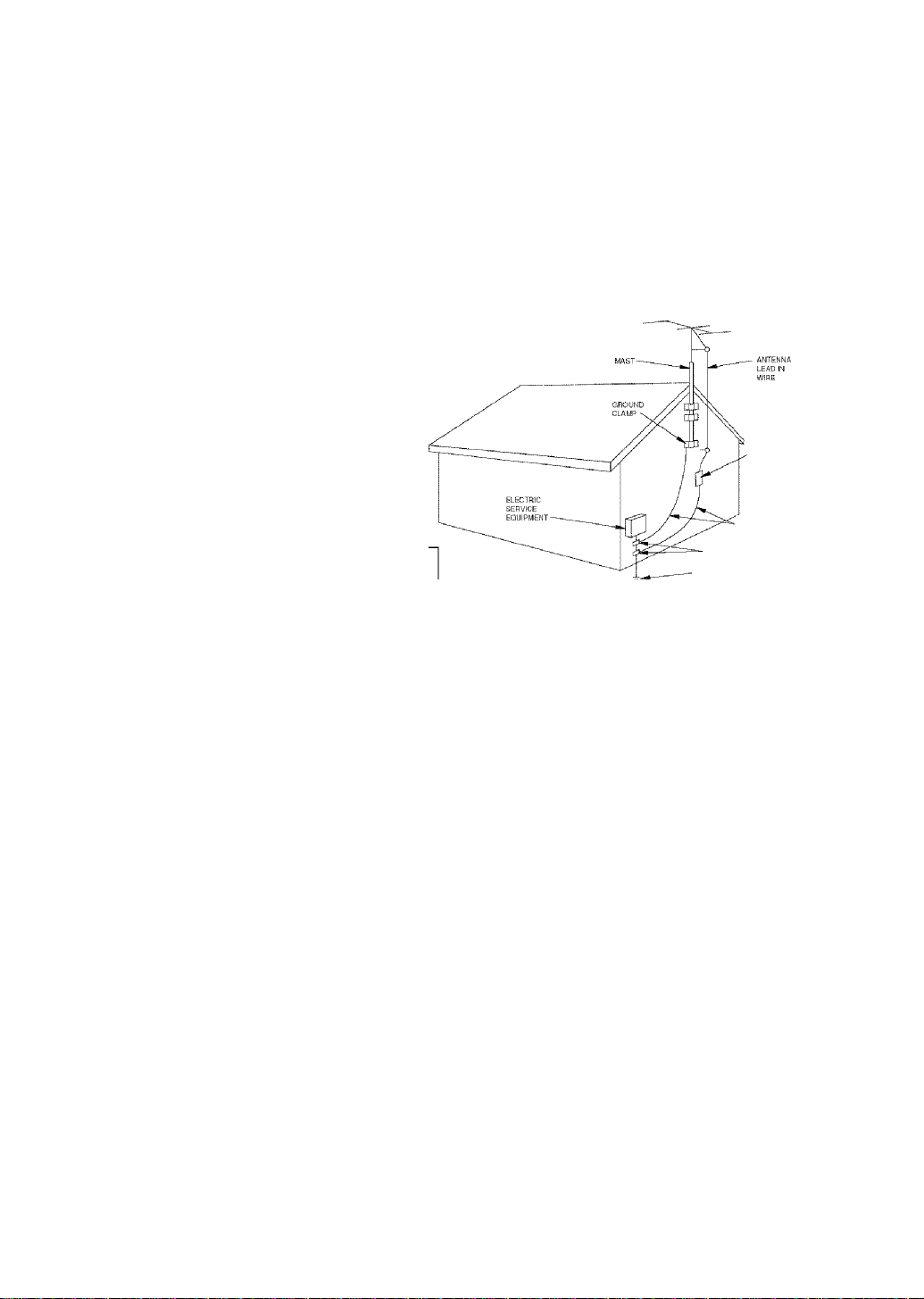
EXAMPLE OF ANTENNA GROUNDING
ANTENNA
DtSCHARGEUNlT
[NEC SECTION 610-20)
GROUNDING CONDUCTORS
(NEC SECTION 610-21)
GROUND CLAMPS
POWER SERVICE GROUNDING
ELECTRODE SYSTEM
(NEC ART 250. PARTH)
NEC -NATIONAL ELECTRICAL CODE
FCC INFORMATION (for US customers)
IMPORTANT NOTICE ; DO NOT MODIFY THIS
unit:
This product, when installed as indicated in the
instructions contained in this manual, meets FCC
requirements. Modifications not expressly approved
by Yamaha may void your authority, granted by the
FCC, to use the product.
IMPORTANT : When connecting this product to
accessories and/or another product use only high
quality shielded cables. Cable/s supplied with this
product MUST be used. Follow all installation
instructions. Failure to follow instructions could void
your FCC authorization to use this product in the USA.
NOTE : This product has been tested and found to
comply with the requirements listed in FCC
Regulations. Part 1.5 for Class “B” digital devices.
Compliance with these requirements provides a
reasonable level of assurance that your use of this
product iti a residential environment will not result in
harmful interference with other electronic devices.
This equipment generates/uses radio frequencies and,
if not installed and used according to the instructions
found in the users manual, may cause interference
harmful to the operation of other electronic devices.
Compliance with FCC regulations does not guarantee
that interference will not occur in all installations. If
this product is found to be the source of interference,
which can be determined by turning the unit '‘OFF" and
“ON”, please try to eliminate the problem by using one
of the following measures:
Relocate either this product or the device that is being
affected by the interferenee.
Utilize power outlets that are on different brancli (circuit
breaker or fuse) circuits or install AC line filter/s.
In the case of radio or TV interference, relocate/reorient
the antenna. If the antenna lead-in is 300 ohm ribbon
lead, change the lead-in to coaxial type cable.
If these corrective measures do not prodtice satisfactory
results, please contact the local retailer authorized to
distribute this type of product. If you can not locate the
appropriate retailer, please contact Yamaha Electronics
Corp.. U.S.A. 6660 Orangethorpe Ave, Buena Park. CA
90620,
The above statements apply ONLY to those products
distributed by Yamaha Corporation of America or its
subsidiaries.
Page 4

CAUTION: READ THIS BEFORE OPERATING YOUR UNIT.
1 To assure the finest performance, please read this
manual carefully. Keep It In a safe place for future
reference.
2 Install this sound system in a well ventilated, cool,
dry, clean place — away from direct sunlight, heat
sources, vibration, dust, moisture, and/or cold.
Allow ventilation space of at least 30 cm on the top,
20 cm on the left and right, and 20 cm on the back
of this unit.
3 Locate this unit away from other electrical
appliances, motors, or transformers to avoid
humming sounds.
4 Do not expose this unit to sudden temperature
changes from cold to hot, and do not locate this unit
in a environment with high humidity (i.e. a room with
a humidifier) to prevent condensation inside this unit,
which may cause an electrical shock, fire, damage to
this unit, and/or personal injury.
5 Avoid installing this unit where foreign object may
fall onto this unit and/or this unit may be exposed
to liquid dripping or splashing. On the top of this
unit, do not place:
- Other components, as they may cause damage
and/or discoloration on the surface of this unit.
- Burning objects {i.e. candles), as they may cause
fire, damage to this unit, and/or personal injury.
- Containers with liquid in them, as they may fall
and liquid may cause electrical shock to the
user and/or damage to this unit.
6 Do not cover this unit with a newspaper, tablecloth,
curtain, etc. in order not to obstruct heat radiation.
If the temperature inside this unit rises, it may
cause fire, damage to this unit, and/or personal
injury.
7 Do not plug in this unit to a wall outlet until all
connections are complete.
8 Do not operate this unit upside-down. It may
overheat, possibly causing damage.
9 Do not use force on switches, knobs and/or cords.
10 When disconnecting the power cord from the wall
outlet, grasp the plug; do not pull the cord.
11 Do not clean this unit with chemical solvents; this
might damage the finish. Use a clean, dry cloth.
12 Only voltage specified on this unit must be used.
Using this unit with a higher voltage than specified
is dangerous and may cause fire, damage to this
unit, and/or personal injury. YAMAHA will not be
held responsible for any damage resulting from use
of this unit with a voltage other than specified.
13 To prevent damage by lightning, disconnect the power
cord from the wall outlet during an electrical storm.
14 Do not attempt to modify or fix this unit. Contact
qualified YAMAHA service personnel when any
service is needed. The cabinet should never be
opened for any reasons.
15 When not planning to use this unit for long periods
of time (i.e. vacation), disconnect the AC power
plug from the wall outlet.
16 Be sure to read the “TROUBLESHOOTING” section
on common operating errors before concluding that
this unit is faulty.
17 Before moving this unit, press STANDBY/ON to set
this unit in standby mode, and disconnect the AC
power plug from the wall outlet.
18 VOLTAGE SELECTOR (Asia and General models only)
The VOLTAGE SELECTOR on the rear panel of this
unit must be set for your local main voltage
BEFORE plugging into the AC main supply.
Voltages are 110V-120V, 220V-240V AC, 50/60 Hz.
This unit is not disconnected from tiie AC power
source as long as it is connected to tlie watll outlet,
even if this unit itself is turned off. This state is called
standby mode. In this state, this unit is designed to
consume a very small quantity of power.
WARNING
TO REDUCE THE RISK OE FIRE OR ELECTRIC
SHOCK, DO NOT EXPOSE THIS UNIT TO RAIN
OR MOISTURE.
IMPORTANT
Please record the serial number of this unit in the
space below.
MODEL:
Serial No.:
The serial number is located on the rear of the unit.
Retain this Owmer’s Manual in a safe place for future
reference.
FOR CANADIAN CUSTOMERS
To prevent electric shock, match wide blade of plug to
wdde slot and fully insert.
This Class B digital apparatus complies with Canadian
ICES-003. "
We Want You Listening For A Lifetime
YAMAHA and the Electronic Industries Association's Consumer
Electronics Group want you to get the most out of your equipment
by playing it at a safe level. One that lets the sound come through
loud and clear without annoying blaring or distortion - and. most
importantly, without affecting your sensitive hearing.
m
Since hearing damage from loud sounds is often
undetectable until it is too late. YAMAHA and the
Electronic Industries Association^ Consumer
Electronics Group recommend you to avoid
prolonged exposure from excessive volume levels.
Page 5

CONTENTS
INTRODUCTION
FEATURES........................................................................2
GETTING STARTED
Supplied accessories.......................................................3
Installing batteries in the remote control........................3
CONTROLS AND FUNCTIONS
Front panel .....................................................................4
Remote control................................................................6
Front panel display
......................................................
...................................
.........................................................
PREPARATION
CONNECTIONS
Before connecting components
Connecting video components
Connecting audio components
Connecting the antennas ............................................. 13
Connecting an external decoder
Connecting the speakers.............................................. 15
Connecting the power supply cord
Turning on the power....................................................20
BASIC SYSTEM SETTINGS........................................21
Using the basic menu...................................................21
Setting the unit to match your speaker system
SP LEVEL (Setting speaker output levels)..................23
...............................................................
......................................
....................................
.....................................
...................................
...............................
.............
BASIC OPERATION
PLAYBACK.....................................................................24
Input modes and indications.........................................26
Selecting a sound field program...................................27
DIGITAL SOUND FIELD PROCESSING
(DSP)
...........................................................................
Understanding sound fields
FliFi DSP programs......................................................30
CINEMA DSP
Sound design of CINEMA DSP
CINEMA DSP Programs
Sound field effects........................................................33
TUNING...........................................................................34
Presetting stations.........................................................35
Selecting preset stations
SLEEP TIMER
RECORDING..................................................................39
.................................................................
...............................................................
..........................................
..................................
............................................
...............................................
10
31
31
ADVANCED OPERATIC
SET MENU
3
4
8
9
9
12
14
IS
23
Set menu list..................................................................40
Adjusting the items on the set menu.............................40
SOUND ! SPEAKER SET
SOUND 2 SP DISTANCE (speaker distance)
SOUND 3 LFE LEVEL................................................43
SOUND 4 D. RANGE (dynamic range)
SOUND 5 CENTER GEQ
SOUND 6"hP tone CTRL
INPUT I I/O ASSIGN
INPUT 2 INPUT MODE (initial input mode)
OPTION I DISPLAY SET
OPTION 2 MEM. GUARD (memory guard)
OPTION 3 AUDIO MUTE
ADVANCED SETUP MENU.........................................46
REMOTE CONTROL FEATURES
Control area...................................................................47
Setting remote control codes
Controlling other components
SETTING THE SPEAKER LEVELS...........................50
Adjusting the speaker levels during playback
Using the test tone.........................................................50
......................................................................
(speaker mode settings)............................................41
(center graphic equalizer)
(headphone tone control)..........................................44
(input/output assignment) ........................................44
g ■
............
......................
........................................
.............
...........................................
..............
..........................................
.............................
........................................
......................................
..............
40
43
43
44
44
45
45
45
47
48
49
50
ADDITIONAL INFORMATION
EDITING SOUND FIELD PARAMETERS................51
Changing parameter settings........................................51
30
30
31
37
3S
Sound field parameter descriptions
TROUBLESHOOTING
RESETTING THE FACTORY PRESETS
GLOSSARY.....................................................................58
SPECIFICATIONS.........................................................60
.................................................
..............................
..................
52
53
57
Page 6

FEATURES
Built-in 5-channel power amplifier
♦ Minimum RMS output power
[U.S.A. and Canada models]
(0,9% THD, J kHz, 6 Q/8 £1)
Front: ilOW+riOW
Center: ilOW
Surround: ilOW+llOW
[Other models]
(0.9% THD. 1 kHz. 6 Q)
Front:
Center:
Surround:
100W+ lOOW
100 w
100 W+ lOOW
Sound field features
♦
Dolby Pro Logic/Dolby Pro Logic II decoder
♦
Dolby Digital/Dolby Digital + Matrix 6.1 Decoder
DTS/DTS + Matrix 6,1 Decoder
♦
♦
CINEMA DSP: Combination of YAMAHA DSP
technology and Dolby Pro Logic, Dolby Digital or
DTS ^ " "
Virtual CINEMA DSP
SILENT CINEMA ™
Sophisticated AM/FM Tuner
♦ 40-Station random access preset tuning
♦ Atttomatic preset tuning
♦ Preset station shifting capability (Preset editing)
Other features
♦ 192 kHz/24-bit D/A converter
♦ Set menu for optimizitig this unit for your Audio/
Video system
♦ Test tone generator for easier speaker balance
adjustment
♦ 6-channel external decoder input
♦ Optical and coaxial digital audio signal jacks
♦ Sleep timer
♦ Remote control with preset remote control codes
I About this manual
indicates a tip for your operation.
Some operations can be performed by using either the buttons on the main unit or on the remote control. In cases
when the button names tliffer betw'een the main unit and the remote control, the button name on the remote control is
given in parentheses.
This manual is printed prior to production. Design and specifications are subject to change in part for the reason of
the improvement in operativity ability, and others. In this case, the product has priority.
nn|POI-BY|
DIGITAL
Manufactured under license from Dolby Laboratories.
“Dolby”, “Pro Logic”, and the doiible-D symbol are
trademarks of Dolby Laboratories.
SILENT "
CINEMA
“SILENT CINEMA” is a trademark of YAMAHA
CORPORATION.
wm
“DTS” and “DTS Digital Surround” are registered
trademarks of Digital Theater Systems, Inc.
Page 7
GETTING STARTED
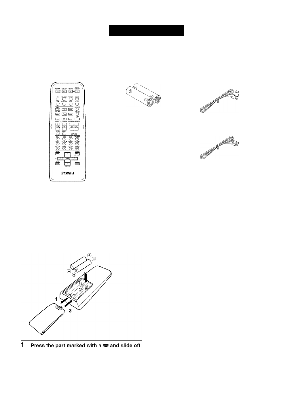
Supplied accessories
Pleuse check that you received all of the following parts.
Remote control Batteries (2)
(AA, R06, UM-3)
AM loop antenna (Europe, U.K., Australia and
Instaliing batteries in the remote control
Insert the batteries in the correct direction by aligning the
+ and - marks on the batteries with the polarity markings
{+ and -) inside the battery compartment.
Indoor FM antenna
(U.S.A., Canada, China, Asia
and General models)
Korea models)
I Notes on batteries
Change all of the batteries if you notice a decrease in
the operating range of the remote control.
Do not use old batteries together with new ones.
Do not use different types of butteries (such as alkaline
and manganese batteries) together. Read the packaging
carefully as these different types of batteries may have
the same shape and color.
If the batteries have leaked, dispose of them
immediately. Avoid touching the leaked material or
letting it come into contact with clothing, etc. Clean the
battery compartment thoroughly before installing newf
batteries.
Do not throw' aw'ay batteries with general house w'aste;
tlispose of them correctly in accordance with your local
regulations.
the battery compartment cover.
2 Insert the two batteries supplied (AA, R06,
UM-3) according to the polarity markings on
the inside of the battery compartment.
3 Slide the cover back on so that it snaps into
place.
If the remote control is without batteries for more than
2 minutes, or if exhausted batteries remain in the
remote control, the contents of the memory may be
cleared. When the memory is cleared, insert new'
batteries, set up the remote control code and program
any acquired functions that may have been cleared.
Page 8
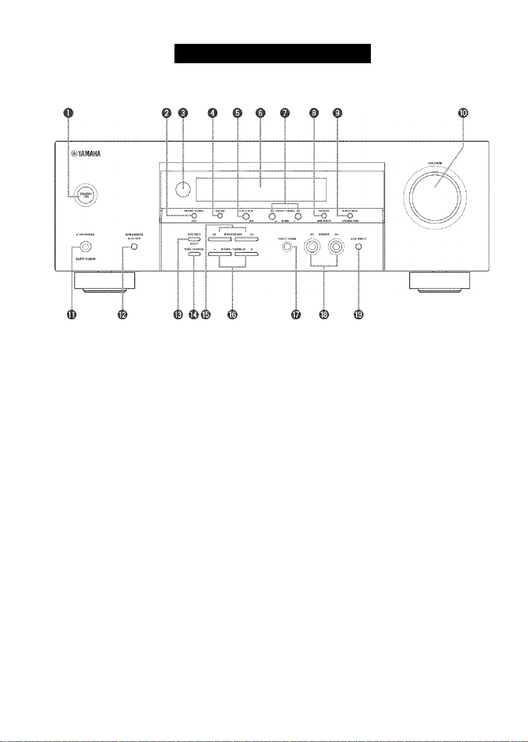
Front panel
CONTROLS ANO FUNCTIONS
O STANDBY/ON
Turns on this unit or sets it to the standby mode. When
you turn on tliis unit, you will hear a click and there wall
be a 4 to 5-second delay before this unit can reproduce
sound.
Note
In standby mode, this unit consumes a small amount of
power in order to receive infrared-signals from the remote
control.
0 PRESET/TUNING
Swatches the function of PRESET/TUNING <1 /O
betw'een selecting a preset station number and tuning (the
colon (:) turns on or off).
(EDIT)
This button is also used to exchange the assignment of
two preset stations wath each other.
© Remote control sensor
Receives signals from the remote control.
O FM/AM
Swatches the reception band betw'een EM and AM.
© A/B/C/D/E
Selects preset station groups A to E w'hen the unit is in
tuner mode.
(NEXT)
Selects the set menu mode w'hen the unit is not in tuner
mode.
o Front panel display
Shows information about the operational status of the
unit.
© PRESET/TUNING <!/[>
Select preset station numbers 1 to 8 when a colon (:) is
displayed in the front panel display.
Select the tuning frequency when a colon {:) is not
displayed in tuner mode.
(SET MENU -/+)
Adjust settings on the set menu w'hen the unit is not in
tuner mode.
© MEMORY (MAN’L/AUTO FM)
Stores a station in the memory.
© TUNING MODE (AUTO/MAN’L MONO)
Sw'itches the tuning mode between automatic and manual.
Page 9

® VOLUiWE
Controls the output level of all audio channels.
This does tiot affect the OUT (REC) level.
(D n PHONES (SILENT CINEMA)
Allows you to enjoy DSP effects when listening with
headphones.
© SPEAKERS A/B/OFF
Selects the set of front speakers connected to the A or B
terminals. To turn off the speakers, press the button
repeatedly and select OFF.
© STEREO (EFFECT)
Switches between normal stereo and DSP effect
reproduction. When you select STEREO, the unit mixes
down all Dolby Digital ;md DTS signals (except the LEE
channel) as well as those 2-channel signals without effect
sounds to the front left and right speakers.
® TONE CONTROL
Sw'itches between Bass (low-frequency response) control
mode and Treble (high-frequency response) control mode.
© PROGRAM O/O
Use to select sound field programs.
© BASS/TREBLE-/+
Increase or decrease low/high-frequency response when
the unit is in Bass/Treble control mode. The sound
changes 2dB each time you press one of these buttons.
Control range; -10 to -l-lOdB.
CONTROLS AND FUNCTIONS
© INPUT MODE
Sets the priority for the types of input signals (AUTO,
DTS, ANALOG) received wdien one component is
connected to tw'o types of input jacks. You cannot set
priority for an audio sources if you have selected 6CH
INPUT as the input source.
© INPUT o/o
Selects the input source you w'ant to listen to or watch.
© 6CH INPUT
Selects the audio source connected to the 6CH INPUT
jacks. This selection takes priority over sources selected
with INPUT (or the input selector buttons on the remote
control).
Page 10
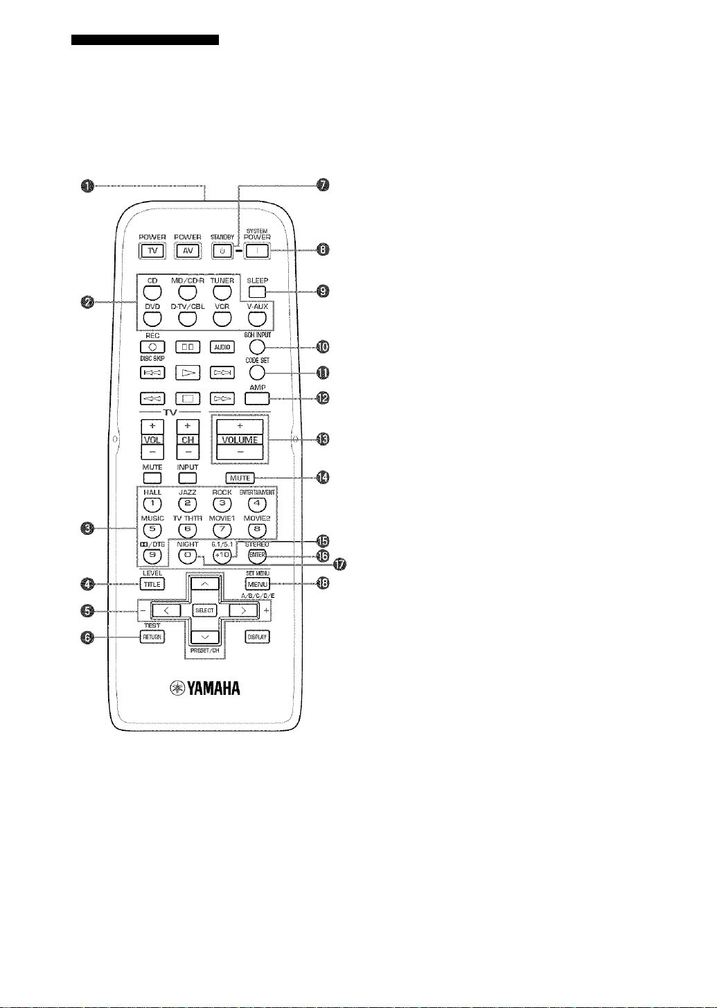
CONTROLS AND FUNCTIONS
Remote control
This section describes the controls and functions of the
remote control when it is set in AMP mode. Please make
sure to select AMP mode before beginning operation.
See “REMOTE CONTROL EEATURES’^on page 47 to
operate other components with this remote control.
O Infrared emitter
Outputs infrared control signals. Aim this emitter at the
component you w'ant to operate.
0
Input selector buttons
Select the input source and change the control area,
0
Sound field program/Numeric buttons
Use to select sound field programs or input numbers.
O LEVEL
Selects the effect speaker channel to adjust.
0 Cursor buttons /\/v'/</> / SELECT
Use to select and adjust sound field program parameters
or SET MENU items.
© TEST
Outputs the test tone to adjust the speaker levels.
0
STANDBY
Sets this unit in standby mode.
© SYSTEM POWER
Tunis on the powder of the unit,
© SLEEP
Sets the sleep tinier.
® 6CH INPUT
Selects the audio source connected to the 6CH INPUT
jacks,
0 CODE SET
Use to set up remote control codes (see page 48).
© AMP
Switches control from a previously selected component
by using the input selector buttons to this unit.
© VOLUME +/-
Increases or decreases the volume level.
Page 11
CONTROLS AND FUNCTIONS
© MUTE
Mutes the sound. Press ugain to restore the audio output
to the previous volume level.
® 6.1/5.1
Switches on or off the Dolby Digital + Matrix 6.1 or DTS
+ Matrix 6,1 decoder,
© STEREO
Switches between normal stereo and DSP effect
reproduction. When you select STEREO the unit rnixes
down all Dolby Digital and DTS signals (except the LEE
chatinel) as well as those 2-channel signals without effect
soutids, to the front left and right speakers.
© NIGHT
Sets the unit in night listening mode.
© SET MENU
Selects the set menu mode.
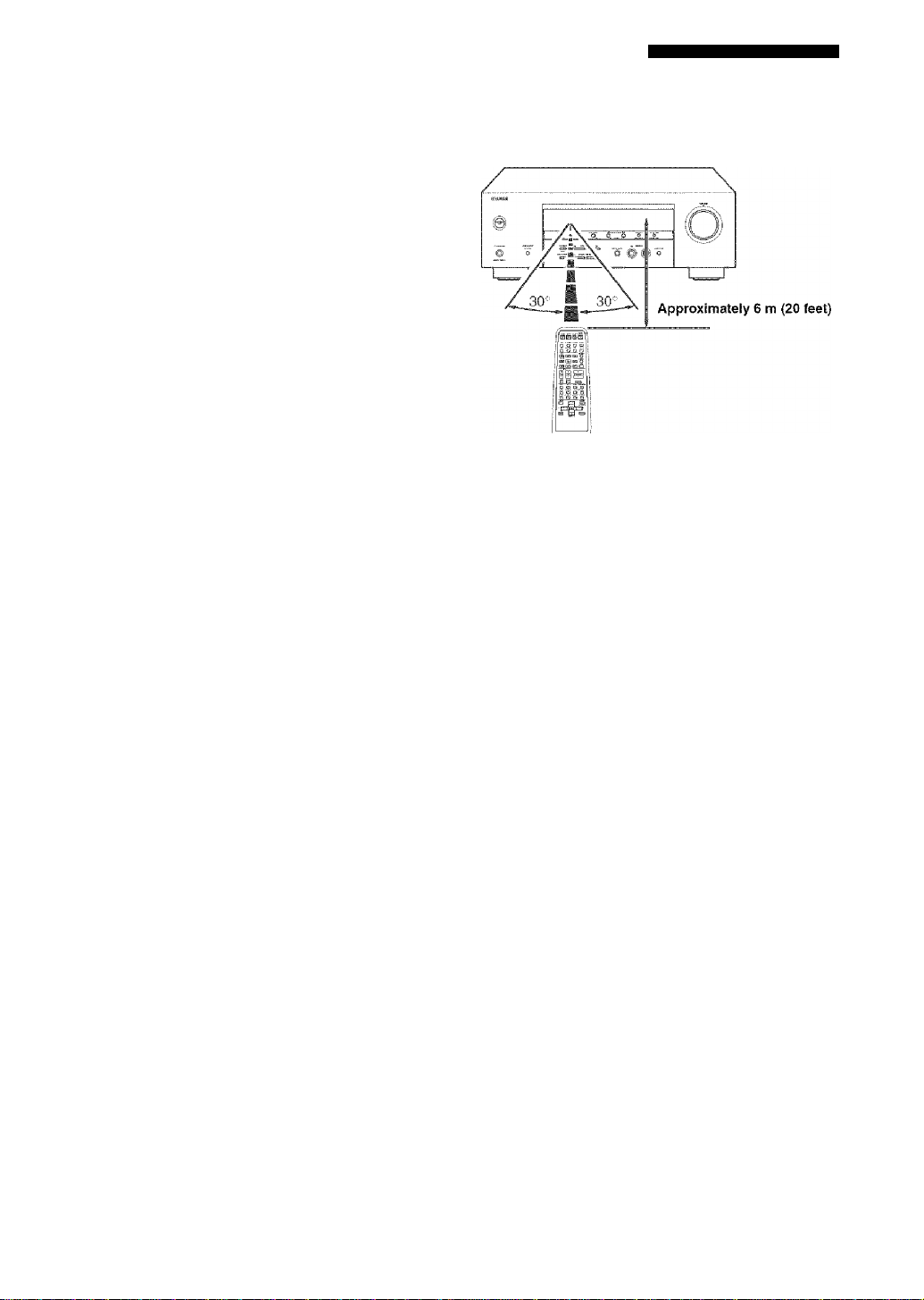
■ Using the remote control
The remote control transmits a directional infrared beam.
Be sure to aim the remote control directly at the remote
control sensor on the main unit during operation.
I Handling the remote control
Do not spill water or other liquids on the remote
control.
Do not drop the remote control.
Do not leave or store the remote control in the
follow ing types of conditions:
- high humidity such as near a bath
- high temperature such as near a heater or stove
- extremely kw temperature
- dusty places
Page 12

CONTROLS AND FUNCTIONS
Front panel display
m m 0
^ ., VCR , ,V-AUX, ,DIV/CBL, , DVD , ,MD/CD
'MATRIX *
■ 00 digital:..?!™ IabI . '• hìfì dsp
' ' DD PL! i laiia asiiaa aatgn maaniMaiH nmmmm uiaaii'^ imia aaaiiii-nasi usua
uu rLii aaaae aiaaa aaaia ■■■£■! aaaaa laaia aaaea
' ' gsasa aaasa aaasa mmammlmmmsm smmmm ■■■■a
: orbivi'i ! 1 f aaaaai eaaaa 1 aBaia ■■■■■laaaaa smmmm ■■■■■
> 1 ^ agggsi ggagg i ggaag giggsa | ggiggs gyaas gaBSS
O Decoder indicators
Wlien any of this unit’s decoders function, the respective
indicator lights up.
O SILENT CINEMA indicator
Lights up when headphones are connected and a sound
field program is selected (see page 27).
O Headphones indicator
Lights up when headphones are connected to the
headphone jaek.
O Input source indicator
Highlights the current input source wdth a cursor.
0
Sound field indicator
Light to indicate the active DSP sound fields.
Presence DSP sound field
- Lisloning position
Left surround
DSP sound field
0
AUTO indicator
Shows that this unit is in the automatic tuning mode.
0
MUTE indicator
Flashes while the MUTE function is on.
0
VOLUME level indicator
Indicates the volume level.
0
PCM indicator
Lights up when this unit is reprodttcing PCM (pulse code
modulation) digital audio signals.
.
Surround back DSP sound field
.. Right surround
DSP sound field
© m
UTD TUNED STEREO MEMORY MUTE VOLUME
aaiae aaaia'aaisi aaaa
aaaaa gaaaa^aaaa aaaa
laaii ■■■iiTiaa» ■■■■
aaaaa gasss^BBiss aasa
è ®® ® ® # < 4 , i 4 © ® 1
© SP A B indicator
Li gilts up to indicate wdiich set of front speakers is
selected.
© NIGHT indicator
Lights up when the unit is set to night listening mode.
© SLEEP indicator
Lights up w'hile the sleep timer is on.
© HiFi DSP indicator
Lights Up when you select a HiFi DSP sound field
program.
© CINEMA DSP indicator
Lights up when you select a CINEMA DSP sound field
program,
© TUNED indicator
Li gilts up W'hen this unit is tuned to a radio station.
© STEREO indicator
Lights up W'hen the unit is receiving a strong signal from
a FM stereo broadcast while the "AUTO” indicator is lit,
© MEMORY indicator
Flashes to show a station can be stored.
® LFE indicator
Lights up W'hen the input signal contains ati LFE signal,
© Input channel indicator
The indicators for the appropriate sound channels light up
when a digital signal from a source is played back.
■R, JUWER/, CD
gaaaa aaaaa aaaaa i
laaia
aaai£| aiiaa ‘ ^ ^
aaaaa
aaaaai aaaaa <. « i \
■ Hil
gassa
■■ail ,rs LrbllbL
aaass| aiaas do ;
„ ■~in.G
lU cIB
::i Ri
B| SRI
&
#
® VIRTUAL indicator
Lights up when using Virtual CINEMA DSP.
0 Multi-information display
Shows the current sound field program name and other
information w'hen adjusting or changing settings.
8
Page 13
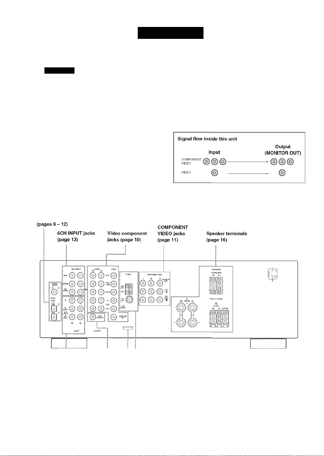
CONNECTIONS
Before connecting components
CAUTION
Do not connect this unit or other coinponents to the
mains power until all connections between the
components have been completed.
Be sure to connect the left channel (L), right channel
(R), "+” (red) and (black) properly. Some
components require different connection methods and
have different jack names. Refer to the operation
instructions for each component you wish to connect to
this unit.
After you have completed all connections, check them
again to make sure they are correct.
The jack names correspond to the names on the input
selector.
DIGITAL INPUT Jacks
■ Connecting to digital jacks
This unit has digital jacks for direct transmission of
digital signals through either a. coaxial or fiber optic
cable. You can use the digital jacks to input PCM, Dolby
Digital and DTS bitstreams. Use digital connections if
you wish to enjoy the multi-channel sound track of DVD
material, etc. with DSP effects. Both digital input jacks
are acceptable for 96 kHz sampling digital signals.
Note
• The OPTICAL jack on this unit conform to the EIA standard.
If you use a fiber optic cable that does not conform to EIA
standard, this unit may not function properly.
Audio component jacks |
(page 12) j
SUBWOOFER OUTPUT
Jack (page 16)
' _ Antenna input terminals
i (page 13)
This Jack is reserved for factory use.
Do not connect any equipment to this Jack.
Page 14
CONNECTIONS
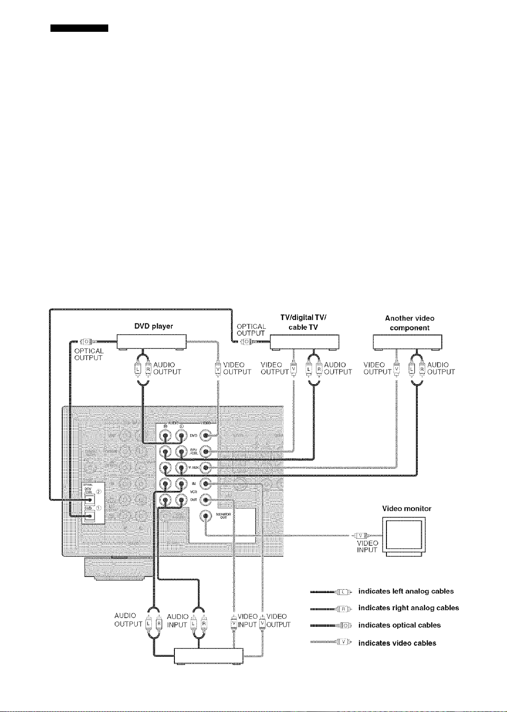
Connecting video components
■ Connecting a video monitor
Connect tlie video input jack on your video monitor to the
MONITOR OUT VIDEO jack,
■ Connecting another video component
Connect the video signal output jack on your component
to the VIDEO jack on this unit.
Connect the audio signal output jacks on the component
to the AUDIO jacks on this unit.
■ Connecting a recording component
■ Connecting a DVD player/digital TV/cable TV
Connect the optical digital audio signal output jack on
your component to the DIGITAL INPUT jack and
connect the video signal output jack on the component to
the VIDEO jack on this unit.
\ I / '
• Use the AUDIO jacks on this unit for a video component
which does not have optical digital output jack. However,
multi-channel reproduction cannot be obtained with audio
signals input from the AUDIO jacks. If you wish to enjoy the
surround sound, use DD/DTS on the remote control (see page
28). "
Connect the atrdio signal input jacks on your video
component to the AUDIO OUT jacks on this unit. Then
connect the video signal input jack on the video
component to the VIDEO OUT jack on this unit for
picture recording.
Connect the audio signal output jacks on your component
to the AUDIO IN jacks on this unit. Then connect the
video signal output jack on the component to the VIDEO
IN jack on this unit to play a source from your recording
component.
Notes
• Once you have connected a recording component to this unit,
• You can also connect a video monitor, DVD player, digital TV,
and cable TV to this unit using the COMPONENT VIDEO
coitnections (see page 11).
• If you connect your video monitor to this unit using a VIDEO
keep its power turned on while using this unit. If the power is
off, this unit may distort the sound from other components.
connection, connect your video source components such as a
DVD player or digital TV to this unit using the VIDEO
comiections.
10
VCR
Page 15

m COMPONENT VIDEO jacks
You cun enjoy high-quality pictures by connecting your
video monitor and video source components to this unit
using COMPONENT VIDEO connections.
COMPONENT Video monitor
VIDEO
•■{jPrì:
CONNECTIONS
i
Note
• If you connect your video monitor to this unit using a
COMPONENT VIDEO connection, connect your video
source components such as a DVD player or digital TV to this
unit using the VIDEO COMPONENT connections.
DVD player
Digital TV/cable TV
indicates component video cables
11
Page 16
CONNECTIONS
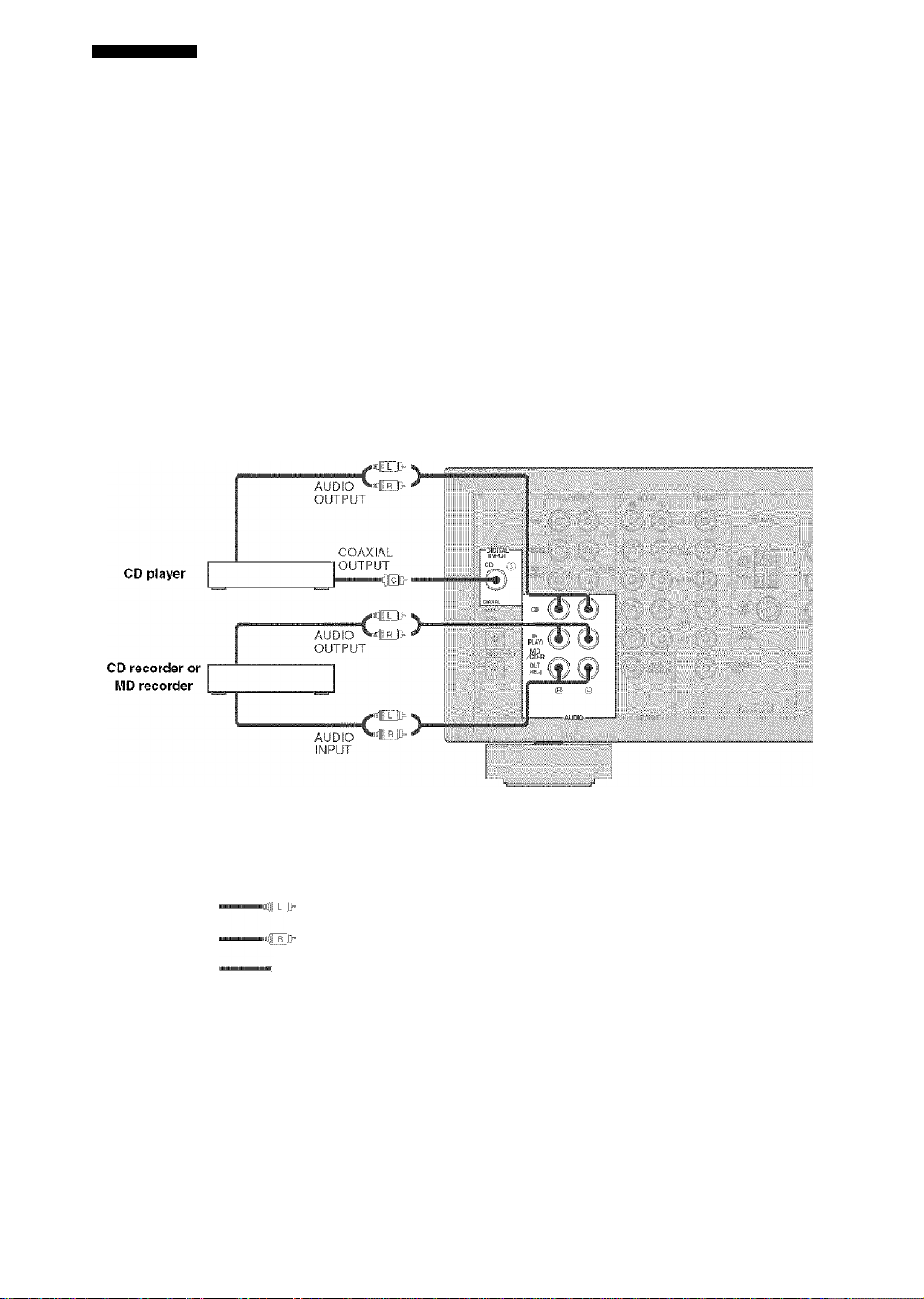
Connecting audio components
■ Connecting a CD player
Connect tlie coaxial digital output jack on your CD player
to the DIGITAL INPUT CD jack on this unit.
Cif)'.
• Use the AUDIO jacks on this unit to connect to a CD player
that does not have a COAXIAL DlCdTAL OUTPUT jack, or
to record trom CD players.
■ Connecting a CD recorder or MD
recorder
Connect the input jacks on your CD recorder or MD
recorder to the MD/CD-R OUT (REC) jacks.
Connect the output jacks on your CD recorder or MD
recorder to the MD/CD-R IN (PLAY) jacks to play a
source from your recording component.
Note
• uiice you have connected a recording component to this unit,
keep its power turned on while using this unit. If the power is
off, this unit may distort the sound from other components.
12
indicates left analog cables
indicates right analog cables
;Mlu indicates coaxial cables
Page 17
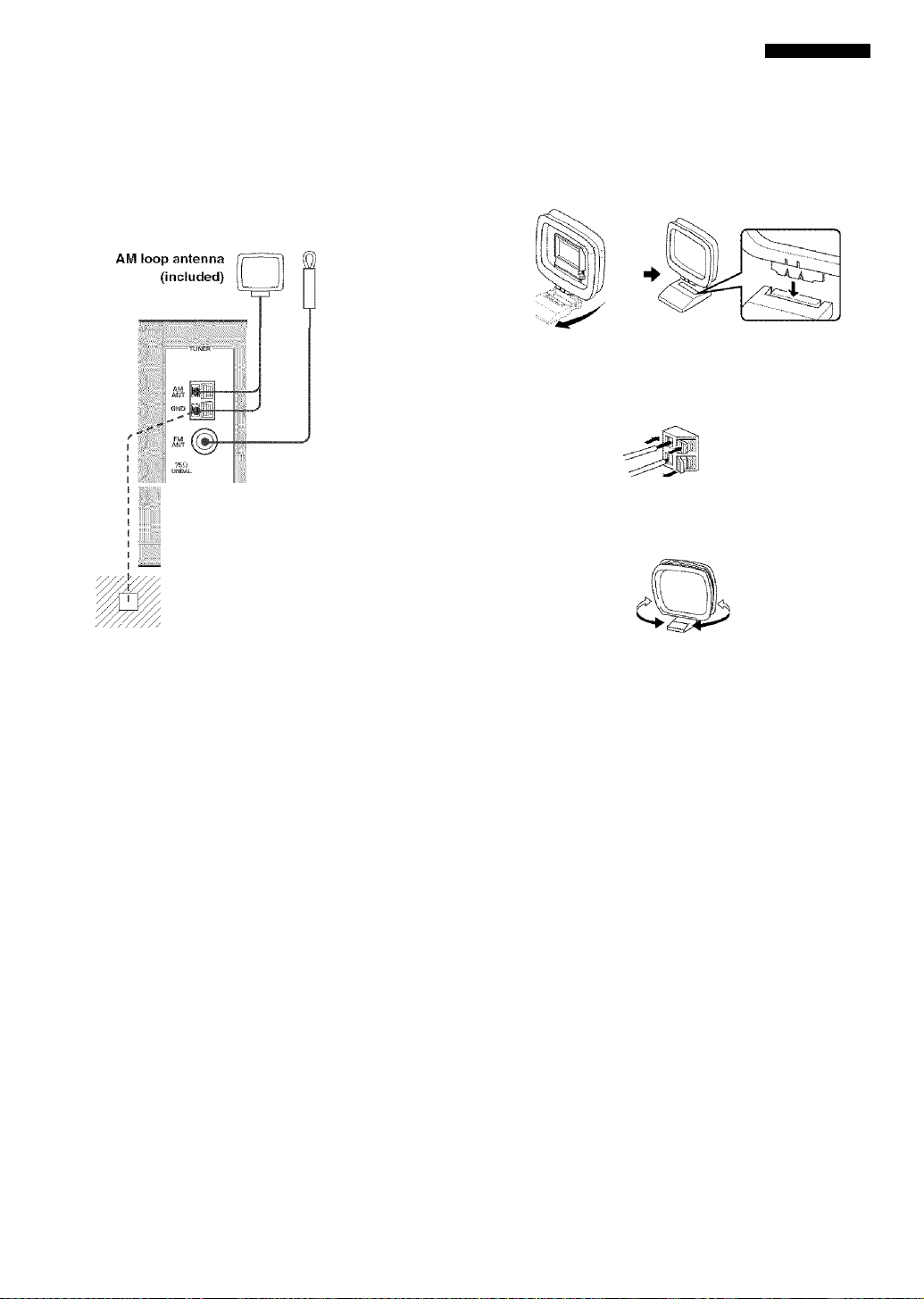
Connecting the antennas
CONNECTIONS
Both AM and FM indoor antennas are inclttded with this
unit. In general, these antennas should provide sufficient
signal strength.
Connect each antenna correctly to the designated
terminals.
Indoor FM
antenna
(included)
Ground {GND terminal)
For maximum safety and minimum
interference, connect the antenna GND
temiinal to it good earth ground. A good
earth ground is a metal stake driven into
moist earth.
■ Connecting the AM loop antenna
1 Set up the AM loop antenna, then connect it
to the terminals on this unit.
Press and hold the tab to insert the AM loop antenna lead wires into the AM ANT and GND terminals.
Orient the AM loop antenna for the best reception.
Notes
• The AM loop antenna should be placed away from this unit.
• The AM loop antenna should always he connected, even if an
outdoor AM antenna is connected to this unit.
• A properly installed outdoor antemia provides clearer
reception than an indoor one. If you experience poor reception
quality, an outdoor antenna may improve the quality. Consult
the nearest authorized YAMAHA dealer or sendee center
about the outdoor antennas.
13
Page 18
CONNECTIONS
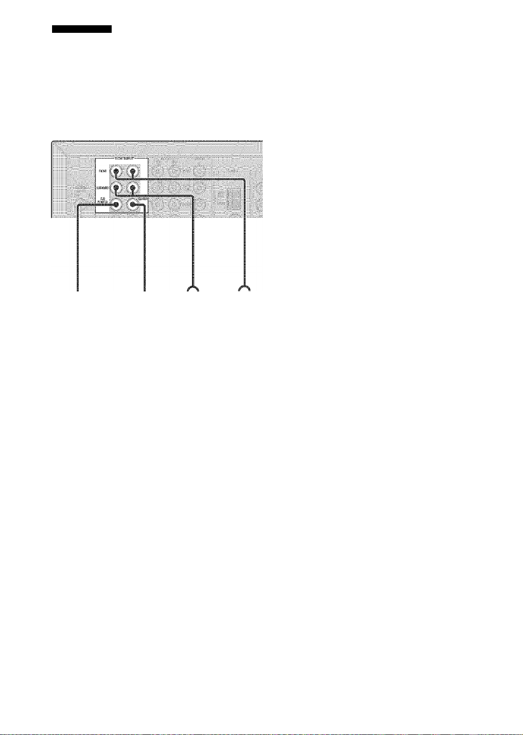
Connecting an external decoder
This unit is equipped with 6 additional input jacks
(FRONT left and right, CENTER, SURROUND left and
right and SUBWOOFER) for discrete multi-channel input
from a component equipped with a multi-channel decoder
and 6 channel output jacks such as a DVD/Super Audio
CD player.
U
CENTER SURROUND
SUBWOOFER
DVD/Super Audio CD player
iJ
FRONT
Notes
• When you select 6CH INPUT as the input source, this unit
automatically turns ot'f the digital sound field processor, and
you cannot select sound field programs.
• When headphones are used, only front L/R channels are
output.
14
Page 19
CONNECTIONS
Connecting the speakers
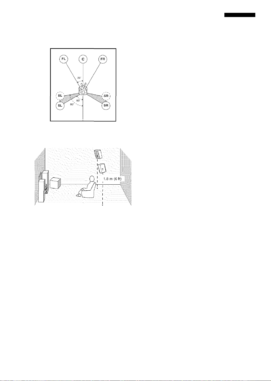
I Speaker placement
The speaker layout above show's the standard ITU-R
speaker setting. You can use it to enjoy CINEMA DSP,
multi-channel audio sources.
Subwoofer
The use of a subwoofer, such as the YAMAHA Active
Servo Processing Subwoofer System, is effective not only
for reinforcing buss frequencies from any or all channels,
but also for high fidelity reproduction of the LFE (low frequency effect) channel included in Dolby Digital and
DTS software. The position (tf the subwoofer is not so
critical, because low bass sounds are not highly
directional. But it is better to place the subwoofer near the
front speakers. Turn it slightly toward the center of the
room to reduce W'all reflections.
Front speakers (FR and FL)
The front speakers are used for the main source sound
plus effect sounds. Place these speakers an equal distance
from the ideal listening position. The distance of each
speaker from each side of the video monitor should be the
same.
Center speaker (C)
The center speaker is for the center channel sounds
(dialog, vocals, etc.). If for some reason it is not practical
to use a center speaker, you can do without it.
Best results, however, are obtained with the full system.
Align the front face of the center speaker with the front
face of your video monitor. Place the speaker centrally
between the front .speakers and as close to the monitor as
possible, such as directly over or under it.
Surround speakers (SR and SL)
The surround speakers are used for effect and surround
sounds. Place these speakers behind your listening
position, facing slightly inw'urds, about 1.8 m (6 ft) above
the floor.
15
Page 20
CONNECTIONS
■ Speaker connections
Be sure to connect the left channel (L), right channel (R), “+” (red) and (black) properly. If the connections are
faulty, no sound will be heard from the speakers, and if the polarity of the speaker connections is incorrect, the sound
will be unnatural and lack bass.
CAUTION
Use speakers with the specified impedance shown on the rear panel of this unit.
Before connecting the speakers, make sure that the power of this unit is off.
Do not let the bare speaker wares touch each other or do not let them touch any metal part of this unit. This could
damage this unit and/or speakers.
Use magnetically shielded speakers. If this type of speakers still creates the interference with the monitor, place
the speakers away from the monitor.
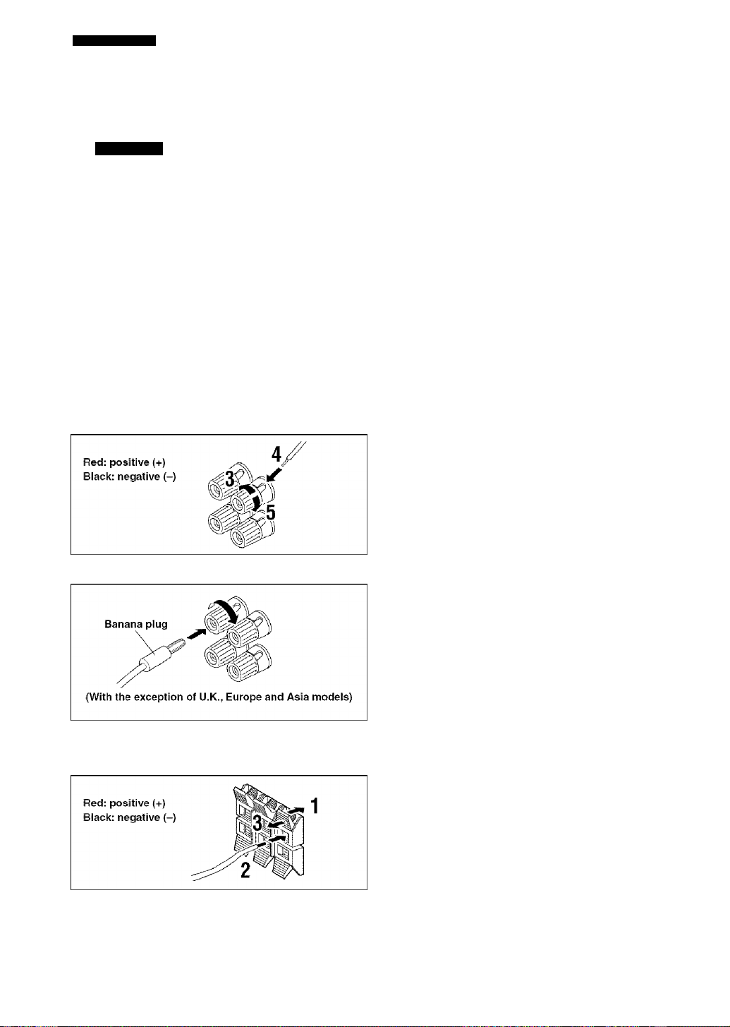
Connecting to the FRONT A SPEAKERS terminals
A speaker cord is actually a pair of insulated cables running side by side. One cable is colored or shaped differently,
perhaps with a stripe, groove or ridges. Connect the striped (grooved, etc.) cable to the “+” (red) terminals on this unit
and your speaker. Connect the plain cable to the (black) terminals.
1 Remove approximately 10 mm (3/8") of
10 mm (3/8”)
insulation from the end of each of the
speaker cables.
2 Twist the exposed wires of the cable
together to prevent short circuits.
3 Loosen the head of the screw.
4 Insert one bare wire into the hole in the side
of each terminal.
5 Tighten the head of the screw to secure the
wire.
Banana plug connections
(With the exception of U.K., Europe and Asia models)
First, tighten the knob and then insert the banana plug
connector into the etid of the corresponding terminal.
Connecting to the FRONT B, CENTER and SURROUND SPEAKERS terminals
1 Press and open the tab.
2 Insert one bare wire into the hole of each
terminal.
16
3 Release the tab to secure the wire.
Page 21
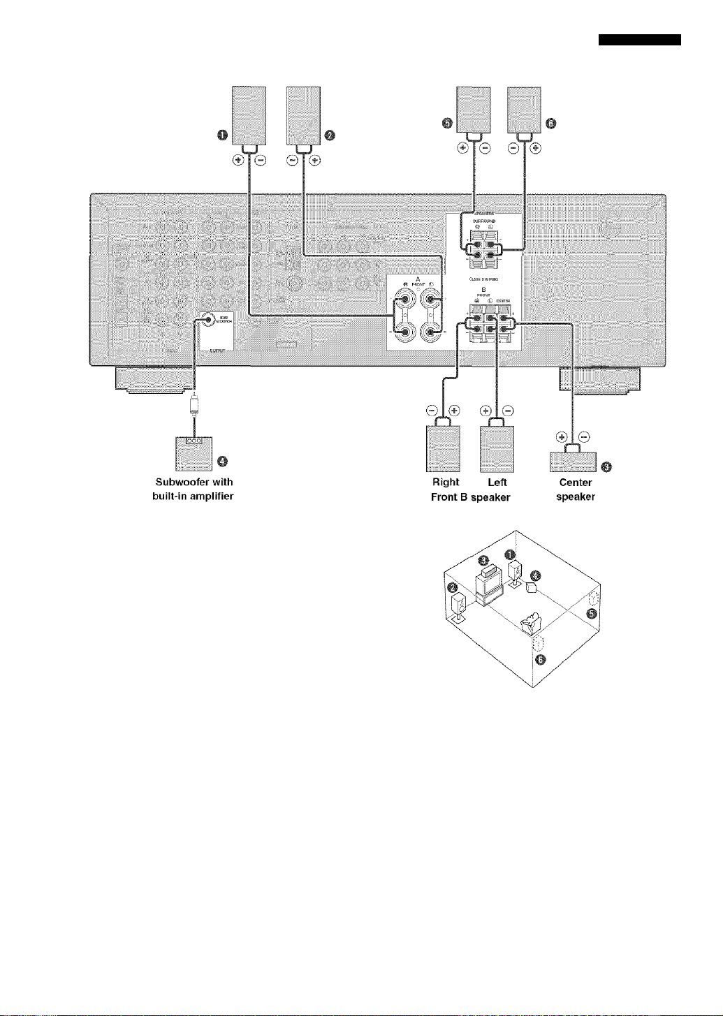
CONNECTIONS
Front A speaker
Right Lett
Surround speaker
Right Left
FRONT SPEAKERS terminals
You can connect up to two speaker systems to these
terminals. When using only one speaker system, connect
it to either of the FRONT A or the FRONT B terminals.
SURROUND SPEAKERS terminals
A surround speaker system can be cotmected to these
terminals.
CENTER SPEAKER terminals
A center speaker can be connected to these terminals.
The diagram shows the speaker layout in the listening
room.
SUBWOOFER jack
When using a subwoofer with built-in amplifier, including the YAMAHA Active Servo Processing Subw'oofer System,
connect the input jack of the subwoofer system to this jack. This unit will direct low bass signals distributed from the
front, center and/or surround channels to this jack in accordance wdth your SPEAKER SET selections. The LEE (lowfrequency effect) signals generated wdien Dolby Digital or DTS is decoded are also directed to this jack in accordance
w ith your SPEAKER SET selections.
Notes
The cut-off frequency of the SUBWOOFER jack is 90 Hz.
If you do not use a subwoofer, allocate the signals to the front left and right speakers by changing the setting of "SOUND I
SPEAKER SET” item “ID BASS" on the set menu to FRONT. - - - Use the control on the suhw'oofer to adjust its volume level. You can also adjust the volume level hy using this unit’s remote control
(see "SETTING THE SPEAKER LEVELS" on page 50).
17
Page 22

CONNECTIONS
Connecting the power supply cord
VOLTAGE SELECTOR Power cord
II
It
(Asia and General models)
■ Connecting the AC power cord
Plug the power cord into an AC w-all outlet.
■ VOLTAGE SELECTOR
(Asia and General models only)
The VOLTAGE SELECTOR on the rear panel of this unit
must be set for j'our local main voltage BEFORE
plugging into the AC main supply. Voltages are:
1 idv -t20 V/220 V - 240 V AC, 50/60 Hz,
18
Page 23

IMPEDANCE SELECTOR switch
(U.S.A. and Canada models only)
CAUTION
Do not change tlie setting of the IMPEDANCE
SELECTOR switch when the unit power is switched on,
as doing so may damage the unit.
If this unit fails to turn on when STANDBY/ON is
pressed on either the front panel or remote control, the
IMPEDANCE SELECTOR switch may not be fully slid
to either position. If this is the case, slide the switch all
the way to either position when this unit is in standby
mode.
Select the switch position (upper or lower) according to
the impedance of the speakers in your system.
CONNECTIONS
(U.S.A. model)
irssi:|
IMPEDANCE SELECTOR switch
Swatch position
Upper
Lowfer
Speaker
FRONT A OR B
CENTER. SURROUND
FRONT A ORB
CENTER, SURROUND
Impedance level
The impedance of each speaker must be 6 Q or higher.
The impedance of each speaker must be 6 Q or higher.
The impedance of each speaker must be 8 Q or higher.
The impedance of each speaker must be 8 Q or higher.
19
Page 24

CONNECTIONS
Turning on the power
Wlien all connections are complete, turn on the power of
this unit.
rrrr
.. ip y
.if:
0:0 :0 g
' • -
1 Press STANDBY/ON (or SYSTEM POWER on
the remote control) to turn on the power of
this unit.
SYSTEM
POWER
Front panel Remote control
The level of the volume, and then the current sound
field program name appear on the front panel
display.
20
Page 25

BASIC SYSTEM SETTINGS
Tlie "BASIC” menu allows you to set some of the basic "SOUND” menu parameters with a minimum of effort. If you
wish to configure the unit more precisely to suit your listening environment, use the more detailed parameters from the
“SOUND” menu instead of those under the "BASIC” menu (see page 40). Altering any parameters in the BASIC menu
will reset all parameters in the “SOUND” menu.
Using the basic menu
Use the remote eoiitnil to make adjiisimenls,
• Press SPEAKERS A/B/OFF on the front panel to select
the front speakers you want to use.
• Make sure you disconnect headphones from this unit.
C33.
j u
^ tj C/
■m if
1 Press AMP.
2 Press SET MENU.
“BASIC MENU” appears on the front panel display.
SET MEWL
MEi
A/B/C/l
4 Press /\ / \/ to change the display to the
setting you want to alter.
1 SETUP
Changes the speaker and amplifier settings to suit the
size of the room you are using. Refer to “Setting the
unit to match your speaker system” on page 23 for
more informatioti,
2 SP LEVEL
Adjusts the output levels of the speakers.
Refer to “SP LEVEL” on page 23 for more
information.
5 Press < / > to enter the desired setting mode.
6 Change the unit settings to suit your
listening environment.
7 Press /\ / \/ to exit from the set menu.
The front panel display changes in the following
order:
Exit
t
'iT '
If the front panel display changes to show anything
other than "BASIC MENU”, press SET MENU until
it displays “BASIC MENU”.
3 Press < / > to enter into the BASIC menu.
“1 SETUP” appears on the front panel display.
-urc
Îî"'
'If
'f
Exit
21
Page 26

BASIC SYSTEM SETTINGS
Basic menu operation sequence
SET MENU
BASIC SOUND INPUT OPTION
22
After altering the “I SETUP" parameters, readjust the output levels of the speakers at "2 SP LEVEL".
See pages 40 - 45 for a detailed explanation of the “SOUND”. “INPUT” and “OPTION" menus.
Page 27

BASIC SYSTEM SETTINGS
Setting the unit to match your speaker system
Follow the instructions below to set the amplifier output
to match the size of your room and speakers. Press /\ / \/
to cycle through parameters 1 through 4, and < / > to alter
the parameter setting.
Factory default settings are highlighted.
(T) ROOM
Settings: S, M, L
Select the size of the room you have installed your
speakers in. Roughly speaking, the room sizes are
defined as follows:
[U.S.A. and Canada models]
S: 16 X 13 ft, 200 ft- (4,8 x 4,0 m, 20 m-)
M: 20 X 16 ft, 300 ft- (6,3 x 5,0 m, 30 nr )
L: 26 X 19 ft, 450 ft’ (7,9 x 5,8 m, 45 m’)
[Other models]
S: 3,6 X 2,8 m, 10 m’
M: 4.8 X 4.0 m, 20 m’
L: 6.3 X 5.0 m, 30 m’
(2) SUBWOOFER
Settings: YES, NONE
Select YES if you have a subwoofer in your system,
or NONE if you do not.
(3) SPEAKERS
Settings: 2, 3, 4, 5 (spk)
Select the number of speakers connected in your
speaker configuration. This number does not include
your subwoofer.
Setting Display
2spk Front L/R
3spk
4spk
5spk
L| C R
ill)
L' C R
SL| SR
isRj
Front L/R, Center,
Surround L/R
Front L/R,
Center
Front L/R,
Surround L/R
Speaker
(4) SET or CANCEL
Select SET to confirm the changes you made. Select
CANCEL to exit SETUP MENU wdthout altering any
of the unit settings. The unit wall output a test tone to
the speakers (see (5)).
(5 Use the test tone to check the speaker levels.
When you select SET in (4), the display changes to
■‘CFIECK : Test Tone” for a few' seconds, and the unit
outputs a test tone to each of the speakers in turn
twice. When the test tone begins, the display changes
to "CHECK OK?-YES”. " "
If the test tone is output at the same volume from all
of the speakers, select "CHECK OK: YES”. Press
to exit from the SETUP menu.
If the volume of the test tone varies between speakers,
press < / > to change the display to “NO”.
Note
• The indicator of the speaker currently outputting the test tone
flashes on the front panel display.
SP LEVEL
(Setting speaker output ieveis)
Use this menu to compare and adjust the test tone output
from each speaker to the output from the front left (or
surround left) speaker so that the volume level for all
speakers is identical. Press /\ /
then adjust the balance using < / >.
Note
• The unit outputs the test tone from the selected speaker and
the front left (or surround left) speaker in turn. The indicator
of the speaker currently outputting the test tone flashes on the
front panel display.
(D L-R
Adjust the balance betw'cen the front left and right
speakers.
(2) C
Adjust the balance betw'een the front left and center
speakers.
(3) SL
Adjust the balance betw'een the front left and
surround left speakers.
(4) SR
Adjust the balance between the surround left and
surround right speakers.
n/ to select a speaker,
(5) SWFR
Adjust the btilance betw'een the front left speaker and
the subwoofer.
Cif)'.
• You can also balance the speaker levels using test tone by
pressing TEST on the remote control.
23
Page 28

PLAYBACK
Press INPUT <1 / o repeatedly (or one of the
input selector buttons on the remote control)
to select the input you desire.
The selected input source name and input mode
appear on the front panel display for a few seconds.
1 Press STANDBY/ON (or SYSTEiW POWER on
the remote control) to turn on the power.
SYSTEM
POWER
Front panel Remote control
2 Turn on the video monitor connected to this
unit
3 Press SPEAKERS A/B/OFF on the front
panel to select the front speakers you want
to use.
SPEAKERS
A/B/OFF
<} lIMPUT P»
CD MD/CD-R TUNER
o o o
DVD D-'FV/CBL VCR V-AUX
sO O O
Front panel
VCR V-AUX DTV/CBJ. , DVD , MD/C&R TUNER CD
Remote control
.DUD. PUTO,
Selected input source Input mode
5 Start playback or select a broadcast station
on the source component.
Refer to the operation instructions for the
component.
6 Adjust the volume to the desired level.
Front panel Remote control
If desired, use TONE CONTROL and
BASS/TREBLE -!+. These controls only effect the
sound from the front speakers.
TOME COPJTfiOL BASS/TREBLE
w/
Front panel
Notes
• If you increase or decrease the high-frequency or the lowfrequency sound to an extreme level, the tonal quality from the
center and surround speakers may not match that of the front
left and right speakers.
• If you have connected a recording component to the VCR
OUT. or MD/CD-R OUT jacks, and you notice distortion or
low volume during playback from other components, try
turning oil the recording compoiieiit.
24
Page 29

PLAYBACK
Select a sound field program if desired.
Press PROGRAM <1 /O (or press AMP to select the
AMP mode, then press one of the field program
buttons repeatedly on the remote control).
See pages 30 - 37 for details about sound field
programs.
JAZZ ROCK iUrtiniSIMilEIJT
o © o o
MUSiO 1\J THTR MOVIE-'
’ or O O 0
ES/DTS MIGHT 6.1/S.T _____
Front panel
Remote control
■ Selecting the 6CH INPUT
Press 6CH INPUT until “6CH INPUT” appears on the
front pane! display.
Qy
Front panel
Remote control
6CH INPUl
Note
If “6CH INPUT” is shown on the front panel display, no other
source can be played. To select another input source, first
]iress 6CH INPUT so that -‘6CH INPUT” disappears from the
front panel display.
■ Playing video sources in the background
You can combine a video image from a video source with
a sound from an audio source. For example, you can
enjoy listening to classical music while having beautiful
scenery from the video source on the video monitor.
Use the input selector buttons to select a video source,
then select an audio source,
CD MD/CD-R TUWER
o
‘»y/CBL VCFI V-AUX
To mute the sound
Press MUTE on the remote control.
“MUTE” blinks on the front
panel display.
To resume audio output, press
MUTE again.
• You can also cancel mute by pressing VOLUME +/-, etc,
• You can adjust the muting level (see page 4.“i),
■ Night listening mode
This mode reproduces dialogue clearly while reducing the
volume of loud sound effects for easier listening at low'
volumes or at night.
Press NIGHT on the remote control. (oT
The NIGHT indicator in the
front panel display lights up.
Press NIGHT once more to
return to nonnal reproduction.
vl/
-i|)-
• You can use night listening mode with any of the sound field
programs.
• Night listening mode may vary' in effectiveness depending on
the input source and surround sound settings you use.
■ When you have finished using this unit
Press STANDBY/ON (STANDBY on the remote control) to set this unit in standby mode.
Front panel
Remote control
25
Page 30

PLAYBACK
Input modes and indications
This unit is equipped with 2 types of input jacks. Do the
follow'ing to select the type of input signals you w'ant to
use.
Press INPUT MODE repeatedly until the desired input mode is shown on the front panel display.
IWPUT MODE
Front panel
VCR V-AUX DWCBL , DVD , MD/CO-R TUNER CD
fiUTi
Selected input source Input mode
HiJ rO Automatically selects input signals in the
following order:
1) Digital signals*
2) Analog signals
DTS Selects only digital signals encoded in DTS.
If no DTS signals are itiput, tio sound is
output.
ftHñl,.06 Selects only analog signals. If no analog
signals are input, no sound is output.
* If this unit detects a Dolby Digital or DTS signal, the decoder
automatically switches to the appropriate sound field program.
\ I /
Cif)'.
You can adjust the default input mode on this unit (see page
44).
Notes
• When you play DTS encoded CD/LDs with the input mode set
to AUTO:
- This unit automatically switches to the DTS decoding
mode. The unit remains in DTS mode (and the ‘
indicator may flash) for up to 30 second after playback of
the DTS source is complete. To manually release the DTS
mode, press INPUT MODE to reselect AUTO.
- The DTS decoding mode may be released if search or skip
operations are performed for more than 30 seconds. To
prevent this, press INPUT MODE to select DTS,
• If the digital output data of the player has been processed in
any way. you may not be able to perform DTS decoding even
if you make a digital coniiectioii betw'een this unit and the
player.
26
Page 31

PLAYBACK
Selecting a sound field program
You can enhance your listening experience by selecting
sound field programs. For details about each program, see
pages 30 - 33,
o o o o
O' u o o
— 2,3
¿2jn Ò o
1 Press AMP.
Press one of the sound field program
buttons on the remote control to select the
desired program.
The name of the selected program appears on the
front panel display.
Jii2Z ROCK ENTOVdWEtir
PROGRAM
Front panel
V-AUX DIV/CBL , , WD/OW? TUMER CD
O © © <3)
MUSIC TV THTR Movie-
or © © ©
tH/DTS MIGHT S.1/5.1
© © © ©
Remote control
____
After selecting the desired program, press the same button repeatedly to cycle through sub-programs If available.
Example; Pressing MOVIE 2 repeatedly
switches the sub-program between
“Adventure” and “General”.
© © © ©
MUSIC TVTHTF! MOVIE 1
* or © © ©
m/DTS NIGHT S.1/5.T
ROCK tUTEHriJHWEUr
© ©
Front panel Remote control
«Ms
Notes
• '1 here .are 9 programs with sub-programs available with this
unit. However, the selection depends on the input signal
fomiat and not all sub-programs can he used with all input
signal formats.
• You caimot use the digital sound field processor with a source
connected to the 6CH INPUT jacks of this unit or when the
unit is reproducing a digital source with a sampling frequency
greater than 48 kHz.
• The acoustics of your listening room affect sound field
programs. Minimize sound reflections in your room to
maximize the effect created by the program.
• When you select an input source, this unit automatically
selects the last sound field program used with that source,
• When you set this unit in standby mode, it stores the current
source and sound field program in memory and automatically
selects them when you turn on the power again.
• If the unit receives a Dolby Digital or DTS signal when the
input mode is set to AUTO, the sound field program (No. 7-9)
automatically switches to the appropriate decoding program,
• When the unit is reproducing a monaural source with PRO
LOGIC or PRO LOGIC/Enhanced, or PRO LOGIC II Movie,
no sound is output from the front and surround speakers.
Sound can only be lieard from the center speaker. (If “I A
CENTER” on the set menu is set to NONE, tire center chaimel
sound is output from the front speakers.)
VCR V-AUX DW/CBL D3AD MO/Ct» TUNER CD
s”!: 1
'».! ’a, ! i *n.
*n.i
'JCH.UME
- H
bÌ”!
Select a program based on your listening preference. Program
ntimes are just for reference.
27
Page 32

PLAYBACK
m Selecting PRO LOGIC or PRO LOGIC II
You can listen to 2-channel sources decoded into four
discrete channels by selecting PRO LOGIC or five
discrete channels by selecting PRO LOGIC II in program
No. 9 (refer to the hsi on page O i.
-O' u u u
1 Select a 2-channel source and start playback
on the source component.
2 Press AMP.
AMP
3 Press DO/DTS.
m/DTS
VCR V-AUX DIV/CBL D№ TUWER , CO
The display cycles as follows each time you press DO/
DTS:
PRO LOGIC^PRO LOGIC Enhanced-^PRO LOGIC II
Movie-^PRO LOGIC II Music->PRO LOGIC-^.,.,
■ Playing Dolby Digital EX or DTS ES
material
Press 6.1/5,1 to turn on the Dolby Digital -l- Matrix 6.1 or
DTS -I- Matrix 6.1 decoder.
S, 1/5.1
(rial
(Example)
WSTiK
VCR V-AUX DIV/CBL D\JD WO/OW? TUNER CD
loj
! ! ■y ."*1 g
i"*l i “
agli S
The display changes AUTO-yMatrix 6.1—/OFF each time
6.1/5.1 is pressed.
AUTO:
Automatically switches Dolby Digital -I-
Matrix 6.1 and DTS -I- Matrix 6.1 depending
on the signal. Virtual surround back speaker
does not work for 5.1- channel sources.
Matrix 6.1:
Produces 6-channel playback of the input
source using the Matrix 6.1 decoder. The
virtual surround back speaker can be used
when playing a 5.1-channel source.
OFF:
Virtual surrountl buck speaker does not
work.
Notes
Some 6.1-channel compatible discs do not have a signal (flag)
that this unit can automatically detect. Select “Matrix 6.1" to
play these kinds of discs with 6.1 -chaimel sound.
6.1 -channel playback is not possible even if you press 6.1/5.1
in the following cases:
- When effects are turned off
- When the source connected to the 6CH INPUT jacks is
being played.
- When the unit is reproducing a Dolby Digital KARAOKE
source.
- When headphones are connected to the PHONES jack.
The 6.1/5.1 setting resets to AUTO wlien you turn the unit
power off.
• You can select PRO LOGIC. PRO LOGIC Enhanced. PRO
LOGIC II Movie, and PRO LOGIC II Music by pressing
PROGRAM <] / D» on the front panel repeatedly.
28
Page 33

PLAYBACK
m Virtual CINEMA DSP
With Virtual CINEMA DSP, you can enjoy all sound field
programs without surround speakers. It creates virtual
speakers to reproduce a natural sound field.
You can listen to virtual CINEMA DSP by setting "1C
SURR" in the set menu to NON. Sound field processing
changes to Virtual CINEMA DSP automatically.
• If you turn off the sound effects, no sound is output from the
• If you turn off the sound effects wdiile the unit is reproducing
Note
• Virtual CINEMA DSP tvill not activate, even when 1C SURR
• The volume may be greatly reduced wiren you turn off the
is set to “NONE" (see page 42) in the foliowing cases:
- When the 5ch Stereo, DOLBY DIGITAL, Pro Logic, Pro
Logic il, or DTS program is selected.
- When the sound effect is turned off.
- When 6CH INPUT is selected as the input source.
\ • /
• During stereo reproduction, you can display information such
- When a digital signal witlt a sampling frequency greater
than 48 kHz is input to this utiit.
- When using tile test tone.
- When connecting the headphones,
■ To listen with headphones
(While playing a source)
1 Press AMP.
(SILENT CINEMA)
The SILENT CINEMA mode allows you to enjoy multi
channel music or movie sound, including Dolby Digital
and DTS surround, through ordinary headphones.
SILENT CINEMA activates automatically whenever you
connect headphones to the PHONES jack while listening
to CINEMA DSP or HiFi DSP sound field programs. The
“SILENT CINEMA” indicator lights up on the front
panel display, (If the sound field programs are off, you
listen with normal stereo reproduction.)
Notes
2 Press /\ / \T to display the information about
(Format): Tlie display shows the signal format. When the
• This feature is not available when 6CH INPUT is selected or
the unit is receiving a digital signal wdth a sampling frequency
greater than 48 kHz.
• The sound from the LFE channel will he mixed and output
from the headphones.
■ Normal stereo reproduction
Press STEREO to turn off the sound effect
for norma! stereo reproduction.
Press STEREO again to turn the sound effect back
STEREO
(enter)
Notes
center speaker or surround spetikers.
sound from a Dolby Digital or DTS signal, the dynamic range
of the signal is automatically compressed and the unit will mix
the sounds of the center and surround speaker channels and
output tltem from the front speakers.
sound effects or if you set “SOUND 4 D. RANGE (dyiumiic
range)” on the set menu to MIN. In this case turn on the sound
effect,
as the type, format and sampling frequency of the signal input
from the components coniiecfed to this unit.
the input signal.
unit cannot detect a digital signal it
automatically sw'itches to analog input,
in: The display shows the number of input signal
source channels, as follows: For multi-channel
soundtrack such as front 3 channels, surround 2
channels and LFE, the display show's “3/2/
LFE”.
fs: The display show's the sampling frequency.
When the unit is unable to detect the sampling
frequency “Unknow-n” show's in the front panel
display.
rate: The display show's the bit rate. When the unit is
unable to detect the bit rate "Unknow'n” show's
in the front panel display,
fig; The display show's the flag - data encoded in a
DTS or Dolby Digital signal that causes this
unit to automatically switch to the appropritite
decoder for playback.
Front panel Remote control
29
Page 34

DIGITAL SOUND FIELD PROCESSING (DSP)
Understanding sound fields
A sound field is defined as the “characteristic sound reflections of a
particular space,” In concert halls and other music venues, we hear
early reflections and reverberations as well as the direct sound
produced by the artist(s). The variations in the early reflections and
other reverberations among the different music venues is what gives
each venue its special and recognizable sound quality,
YAMAHA sent teams of sound engineers all around the world to
measure the sound reflections of famous concert halls and music
venues, and collect detailed sound field information such as the
direction, strength, range, and delay time of those reflections. Then
we stored this enormous amount of data in the ROM chips of this
unit.
■ Recreating a sound field
Recreating the sound field of a concert hall or an opera house requires localizing the virtual sound sources in your
listening room. The traditional stereo system that uses only two speakers is not capable of recreating a realistic sound
field. YAMAHA’S DSP requires four effect speakers to recreate sound fields based on the measured sound field data.
The processor controls the strength and delay time of the signals output from the four effect speakers to localize the
virtual sound sources and fully encompass the listener.
HiFi DSP programs
The following list gives you a brief description of the sound fields produced by each of the sound field programs. Keep
in mind that most of these are precise digital recreations of actual acoustic environments.
No. Program Features
1 CONCERT HALL
(except China
model)
HALL IN CHINA
(China model only)
A large round concert hall with a rich surround effect. Pronounced reflections from all directions
emphasize the extension of sounds. The sound field has a great deal of presence, and your virtual
seat is near the center, close to the stage.
A large, extremely famous concert hall in China with approx. 650 seats on the first floor and
approx. 500 seats on the second floor. The clear sound field of this gorgeous and majestic hall is
suited especially for classic music. Your virtual seat is near the center on the first floor.
2 JAZZ CLUB This is the sound field at stage front in ’The Bottom Line”, a famous New York jazz club, that
seats up to 300 people. Its wide left to right seating arrangement offers a real and vibrant sound.
3 ROCK CONCERT The ideal program for lively, dynamic rock music. The data for this program was recorded at LA's
"hottest” rock club. The listener's virtual seat is at the center-left of the hall.
4 ENTERTAINMENT/
Disco
This program recreates the acoustic environment of a lively disco in the heart of a big city. The
sound is dense and highly concentrated. It is also characterized by a high-energy, "immediate”
sound.
ENTERTAINMENT/
5ch Stereo
Using this program increases the listening position range. This is a sound field suitable for
background music at parties, etc.
30
Page 35

CINEMA DSP
Sound design of CINEMA DSP
Filmmakers intend for the dialog to be located right on the screen, the effect sound a little farther back, the music spread
even farther back, and the surround sound around the listener. Of course, all of these sounds must be synchronized with
the images on the screen.
CINEMA DSP is an upgraded version of YAMAHA DSP specially designed for movie soundtracks, CINEMA DSP
integrates the DTS, Dolby Digital, and Dolby Pro Logic surround sound technologies with YAMAHA DSP sound field
programs to provide a surround sound field. It recreates comprehensive movie sountl design in your audio room. In
CINEMA DSP sound field programs, YAMAHA’s exclusive DSP processing is added to the Front left and right, and
Center channels, so the listener can enjoy realistic dialogue, depth of sound, smooth transition between sound sources,
and a surround sound field that goes beyond the screen.
When a DTS or Dolby Digital signal is detected, the CINEMA DSP sound field processor automatically chooses the
most suitable sound field program for that signal.
L SURROUND SOUND FIELD
PRESENCE SOUND FIELD
R SURROUND SOUND FIELD
In addition to the DSP, this unit is equipped with a variety of precise decoders; Dolby Pro Logic decoder for Dolby
Surround sources, Dolby Pro Logic II decoder for Dolby Surround and 2-channel sources, Dolby Digital/DTS decoder
for multi-channel sources and Dolby Digital -l- Matrix 6.1 or DTS -l- Matrix 6.1 decoder for adding a surround back
channel (the surround buck channel is outputted from virtual surround back speaker). You can select CINEMA DSP
programs to optimize these decoders and the DSP sound patterns depending on the input source.
CINEMA DSP Programs
The following list gives you a brief description of the sound fields produced by each of the sound field programs. Keep
in mind that most of these are precise digital recreations of actual acoustic environments. Select the sound field program
that you feel sounds best regardless of the name and description given for it below.
For audio-video sources: No. 4 to 6
No. Program
4 ENTERTAINMENT/
Game
5 MUSIC VIDEO
6 TVTHEATER/
Mono Movie
This program adds a deep and spatial feeling to video game sounds.
This program lends an enthusiastic atmosphere to the sound, giving you the feeling you are at an
actual jazz or rock concert.
This program is provided for reproducing monaural video sources (such as old movies). The
program produces the optimum reverberation to create sound depth using only the presence sound
field.
Features
TVTHEATER/Variety/
Sports
Though the presence sound field is relatively narrow, the surround sound field employs the sound
environment of a large concert hall. This effect enhances the experience of watching various TV
programs such as news, variety shows, music programs or sports programs.
31
Page 36

CINEMA DSP
For movie programs
No. Program Features
7 MOVIE
THEATER 1
Spectacle This program creates the extremely wide sound field of a 70-mni movie theater. It
precisely reproduces the source sound in detail, making botli the video atid the sound field
incredibly real. This is ideal for any kind of video source encoded with Dolby Surround,
Dolby Digital or DTS (especially large-scale movie productions).
Sci-Fi This program clearly reproduces dialog and sound effects in the latest sound form of
science fiction films, thus creating a broad and expansive cinematic space amid the
silence. You can enjoy science fiction films in a virtual-space sound field that includes
Dolby Surround, Dolby Digital and DTS-encoded softwaire employing the most advanced
techniques.
8 MOVIE
THEATER 2
Adventure This program is ideal for precisely reproducing the sound design of the newest 70-mm and
multichannel soundtrack films. The sound field is made to be similar to that of the newest
movie theaters, so the reverberations of the sound field itself are restrained as much as
possible.
General This program is for reproducing sounds from 70-mm and multichannel soundtrack films,
and is characterized by a soft and extensive sound field. The presence sound field is
relatively narrow. It spatially spreads all around and tow'ard the screen, restraining the
echo effect of conversations without losing clarity.
9 Straight Decode The built-in decoder reproduces source sounds and sound-effects precisely.
No DSP effect is applied in this program.
Enhanced Mode This program ideally simulates the multi-surround speaker systems of tlie 35-mm film
theaters. Dolby Pro Logic decoding, Dolby Digital decoding or DTS decoding and digital
sound field processing create precise effects without altering the original sound orienta
tion.
The surround effects produced by tliis sound field w'rap around the view'er naturally from
the back to tlie left and right, and tow ard the screen.
Straight Decode
This unit is equipped with various precise decoders;
• Dolby Digital/DTS decoder for multi-channel reproduction of the original sound
• Dolby Pro Logic/Pro Logic II decoder for multi-channel reproduction of 2-channel sources
Select any of the Straight Decode modes in Program No. 9 (except for the sub-program ‘"Enhanced”) as showm in the
above list to use any of these decoders for reproducing the original sound without any sound effects added. In this case,
no DSP effect is applied and the DSP indicator turns off.
Note
• When playing a monaural source with a CINEMA DSP program, the source signal is directed to the center channel, and the front
and snrround speakers output effect sounds.
32
Page 37

CINEMA DSP
Sound field effects
The 6-channel soundtracks found on 70-mm fdni produce precise sound field localization and rich, deep sound without
using matrix processing. This unit's MOVIE THEATER programs provide the same quality of sound and sound
localization that 6-channel soundtracks do. The built-in Dolby Digital or DTS decoder brings the professional-quality
sound designed for movie theaters into your home. With this unit’s MOVIE THEATER programs, you can use Dolby
Digital or DTS technology to recreate a dynamic sound that gives you the feeling of being in a public theater.
Dolby Digital/DTS + DSP sound field effect
These programs use YAMAHA's tri-field DSP processing
Presence DSP sound field
on each of the Dolby Digital or DTS signals for the front,
left surround, and right surround channels. This
processing enables this unit to reproduce the immense
sound field and surround expression of a Dolby Digitalor DTS-equipped movie theater without sacrificitig the
clear separation of all channels.
.
Left surround DSP
sound field
\
Right surround DSP
sound field
■ Dolby Digital/DTS + Matrix 6.1 + DSP sound field effect
These programs provide you with the maximum experience of the spacious surround effects by adding an extra
surround back DSP sound field created from the virtual surround back speaker.
Dolby Pro Logic + DSP sound field effect
Most movie material has 4-channel (left, center, right, and
Presence DSP _
sound field
surround) sound information encoded by Dolby Surround
matrix processing and stored on the left and right tracks.
These signals are processed by the Dolby Pro Logic
decoder. The MOVIE THEATER programs are designed
to recreate the spaciousness and delicate nuances of
sound that tend to be lost in the encoding and decoding
processes.
Surround DSP
sound field
■ Dolby Pro Logic II
Dolby Pro Logic II decodes Dolby Surround software into 5 discrete full-range channels (3 channels in front and 2
channels in surround). There are 2 modes; MOVIE for movies and MUSIC for 2-channel audio sources.
33
Page 38

TUNING
There are 2 methods of tuning; automatic and manual.
Automatic tuning is effective when station signals are
strong and there is no interference.
Automatic tuning
ifíSíiOfl
4 1
1 Press iNPUT o /1> (or TUNER on the remote
control) to select TUNER as the input source.
IIVPUT &■
Front panel Remote control
2 Press FM/AM to select the reception band.
"FM” or “AM” appears on the front panel display.
FM/AM
e
C Ivi iM
4 Press PRESET/TUNING <i / o once to begin
automatic tuning.
Press O to tune in to a higher frequency, or press <1
to tune iti to a lower frequency.
■O PRESET/TUNING C>-
”0
- SÍTMENU 4-
♦
VCR V-AUX DWyCBL DWi
When the unit is tuned in to a station, the “TUNED”
indicator lights up and the frequency of the station
received is shown on the front panel display.
■ Manual tuning
If the signal from the station you are trying to select is
weak, tune in to it manually,
1 Select TUNER and the reception band
following steps 1 and 2 described in
“Automatic tuning” at left.
2 Press TUNING MODE (AUTO/MAN’L MONO)
until the “AUTO” indicator disappears from
the front panel display.
TUNING MODE
AUTO
Disappears
Press TUNING MODE (AUTO/MAN’L MONO)
so that the “AUTO” indicator lights up on the
front panel display.
TUNING MODE
(Qs
AUT0/U;sN'
AUTO
Lights up
If the colon (:) appears on the front panel display,
tuning is not possible. Press PRESET/TUNING
(EDIT) to turn it off.
PRESET/TUNING
34
If the colon (:) appears on the front panel display,
tuning is not possible. Press PRESET/TUNING
(EDIT) to turn it off.
PRESET/TUNING
Press PRESET/TUNING
VCR V-AUX DTV/CBl DVD
■<] PRESET/TUNING O-
<l /1> to tune in to the
desired station manually.
Hold down the button to
continue searching.
Note
• Manually tuning in To an FM station will automatically change
the reception inode to monaural to increase the signal quality.
Page 39

Presetting stations
■ Automatically presetting FM stations
You can use the automatic preset tuning feature to store
FM stations. This function enables the unit to
automatically tune in to FM stations with strong signals,
and to store up to 40 (8 stations in 3 groups, A1 through
E8) of those stations in order. You can then recall any
preset station easily by selecting the preset number.
is
.....
1 Press FM/AM to select the FM band.
FM/AM
Press TUNING MODE (AUTO/MAN’L MONO)
until the “AUTO” indicator iights up on the
front panel display.
TUNING MODE
Press and hold MEMORY (MAN’L/AUTO FM)
for more than 3 seconds.
The preset number, the “MEMORY” and “AUTO”
itidicators flash. After about 5 seconds, automatic
presetting starts from the frequency currently
displayed and proceeds toward the higher
frequencies.
AUTO
Lights up
Notes
• Any stored station data existing under a preset number is
cleared when you store a new station under that preset number.
• If the number of the received stations does not reach 40 (E8),
automatic preset tuning has automatically stopped after
searching all stations.
• Only FM stations with sufficient signal strength are stored
automatically by automatic preset tuning. If the station you
want to store is weak in signal strength, tune in to it manually
in the monaural mode, and store it by following tlie procedure
described in “Manually presetting stations” on page 36.
Automatic preset tuning options
You can select the preset number from which this unit
will store FM stations and/or begin tuning tow'ard lower
frequencies.
After pressing MEMORY in step 3:
! Press A/B/C/D/E, then PRESET/TUNING <1 / O to
select the preset number under wdiich the first station
will be stored. Automatic preset tuning will stop when
stations have all been stored up to E8.
2 Press PRESET/TUNING (EDIT) to turn off the colon
(:) and then press PRESET/TUNING <1 to begin
tuning toward lower frequencies.
Memory back-up
The memory back-up circuit prevents the stored data
from being lost even if this unit is set in the standby
mode, the power cord is disconnected from the AC
outlet, or the power supply is temporarily cut due to
power failure. However, if the pow'er is cut for more
than one w'eek, the preset stations may be cleared. If
so, store the stations again by using the presetting
station methods.
♦
VCR V-AUk DTV/CBL DVD MB/CETR JUNEHy. CD,,..
When automatic preset tuning is completed, the front
panel display shows the frequency of the last preset
station.
35
Page 40

■ Manually presetting stations
You can store up to 40 stations (8 stations x 5 groups)
manual Ij'.
2,5
Press PRESET/TUNING <l / o to select a
preset station number (1 to 8) while the
“MEMORY” indicator is flashing.
Press [> to select a higher preset station number.
Press <3 to select a low'er preset station number,
<a PRESET/TUNING !>■
f-O
SEf MENU -f
♦
V-AUX DTV/CBl. DVD 1
■“!' ¡1 ¡“"i
Preset number
r’ii i
“s' “T 'L.* s'*. S S
See page 34 for tuning instructions.
VCR V-AUX DIV/CBL D3«3 MOyCM .TUMER,
hi PM 1440 kHz
When tuned in to a station, the front pane! display
shows the frequency of the station received.
2 Press MEMORY (MAN’L/AUTO FM).
The “MEMORY” indicator flashes for about
5 seconds.
MEMORY I /
" ~ MEMORY ~
Y I
Flashes
Press A/B/C/D/E repeatedly to select a preset
station group (A to E) while the “MEMORY”
indicator is flashing.
The group letter appears. Check that the colon (:) is
showing on the front panel display.
Press MEMORY (MAN’IVAUTO FM) on the
front panel while the “MEMORY” indicator is
flashing.
The station band and frequency appear on the front
panel display with the preset group and number you
have selected.
MEMORY
♦
V-AUX DTI//CBL DU®
C3n::iM 1.440 kHz
Shows the displayed station has been stored as C3.
6 Repeat steps 1 to 5 to store other stations.
Notes
• Any stored station data existing under a preset number is
cleared when you store a new station under that preset number.
• The reception mode {stereo or monaural) is stored along with
the station frequency.
36
♦
VCR V-AUX amycBL
[; ;njv| ]440
Preset group
Page 41

Selecting preset stations
You can tune any desired station simply by selecting the
O Ô O Ô
U U Ü u
.iS)- :0-: O:'
■ ■
1 Press A/B/C/D/E (or A/B/C/D/E on the remote
control) to select the preset station group.
The preset group letter appears on the front panel
display and changes each time you press A/B/C/D/E.
A/B/C/D/E gjj
me:
A/B/C/1
Front panel
Press PRESET/TUNING <a/o (or PRESET
/ \/ on the remote control) to select a preset
station number (1 to 8).
The preset group and number appear on the front
panel display along with the station band, frequeticy
and the “TUNED” indicator lights up.
■<} PRESET/TUNING O
-'0
- SET MENU +
Front panel Remote control
Remote control
■ Exchanging preset stations
You can exchange the assignment of two preset stations
w'ith each other. The example below describes the
procedure for exchanging preset station “El” w'ith “A5”.
1 Select preset station “E1” using
A/B/C/D/E and PRESET/TUNING <a / c>.
See “Selecting preset stations” at left.
2 Press and hold PRESET/TUNING (EDIT) for
more than 3 seconds.
“El” and the “MEMORY” indicator flash on the
front panel display.
PRESET/TUNING
3 Select preset station "AS” using
A/B/C/D/E and PRESET/TUNING <3 / O.
“A5” and the “MEMORY” indicator flash on the
front panel display.
VCR V-AUX
iHStFI'l 90.6 I'lH::;:
4 Press PRESET/TUNING (EDIT) again.
The stations stored at the two preset assignments are
exchanged.
PRESET/TUNING VCR V-AUX DW/CBL
El-PS
VCR V-AUX DTV/ÎBL DVD MD/CW? TUNER. CD
C:3~Hri 1440 kHz
Shows the exchange of stations has been
completed.
37
Page 42

SLEEP TIMER
Use this feature to automatically set this unit in the
standby mode after a certain amount of rime. The sleep
timer is useful when you are going to sleep while this unit
is playing or recording a source.
The sleep timer can only be set with the remote control.
• By connecting a commercially available timer to this unit, you
can also set a wake-up timer. Refer to the operation
instructions of the timer.
■ Setting the sleep timer
r
:Ш.ЕГ1 -
I.; i ь-
■ 0: '0: :Q • Ь
□ Г”1 G3 О
□ L'.VJ CD rCJ
1 Select a source and start playback on the
source component.
Press SLEEP repeatedly
to set the amount of time.
Each time you press SLEEP,
the front panel display changes
as show'n below. The SLEEP indicator flashes while
swdtching the amount of time for sleep timer.
Canceling the sleep timer
Press SLEEP repeatedly until “SLEEP OFF”
appears on the front panel display.
After a few seconds, “SLEEP OFF” disappears, and
the “SLEEP” indicator goes off.
Cif)g
The sleep timer setting can also be canceled by pressing
STANDBY on the remote control (or STANDBY/ON on the
front panel) to set this unit to the standby mode.
-b SLEEP 120 min SLEEP 90 min -
- SLEEP OFF SLEEP 30 min ^ SLEEP 60 min
V-AUX OTtlAlBL ОЗЛЭ MD/dfi? TLSNER ,
‘ HiFiDSP
The “SLEEP” indicator lights up on the front
panel display after the sleep timer has been
set.
VCR V-AUX DTY/CBL D№ MO/Catft TUWER , CD ,
38
Page 43

RECORDING
Recording adjustments and other operations are
performed on other recording components. Refer to the
operation instructions for these components for details on
their operation .
ibi b) ni-bi ■
2—
:0. C3
r. ^ n
L~; r.'.’ r::i Ó
EZ: I : [ZD o
Qj L.J
1 Turn on the power of this unit and all
connected components.
2 Select the source component you want to
record from.
Notes
• Jo a test recording before you start an actual recording.
• When this tmit is set in the standby mode, you cannot record
between other components connected to this unit.
• The setting of TONE CONTROL, VOLUME, ‘SP LEVEL"
(page 23 ) and programs does not affect the recorded material.
• A source connected to the 6CH INPUT jacks of this unit
cannot be recorded.
• A given input source is not output on the same REC OUT
channel. (For example, the signal input from VCR 1 IN is not
output on VCR I OUT.)
• Check the copyright laws in your country to record from
records, CDs, radio, efc. Recording of copyrighted material
may infringe copyright laws.
If you playback a video source that uses scrambled or
encoded signals to prevent it from being dubbed, the
picture itself may be disturbed due to those signals.
<q INPUT P»
CD MD/CD-R TUWER
O O O
or OMO D-TV/CBL VCR V-AUX
Ó o
Front panel Remote control
3 start playback (or select a broadcast station)
on the source component.
4 Start recording on the recording component.
39
Page 44

SET MENU
You can set tlie following parameters on the set menu to obtain a better sound from the unit. Change the settings to
reflect the needs of your listening environment.
Set menu list
■fhc set menus aie divided by
categories listed here.
■ BASIC MENU
The BASIC MENU contains the basic parameters that
you must set before using this unit. It consists of the
following menus. See pages 21-23 for a detailed
explanation.
1 SETUP 2 SP LEVEL (Speaker level)
■ SOUND MENU
The SOUND MENU contains parameters for altering
sound output. It consists of the following menus that you
cun use to alter the quality and tone of the sound output
by the system.
1 SPEAKER SET 2 SP DISTANCE (Speaker distance) 3 LFE LEVEL (Low frequency effect level) 4 D. RANGE (Dynamic range) 5 CENTER GEQ (Center graphic equalizer) 6 HP TONE CTRL (Headphone tone control)
■ INPUT MENU
The INPUT MENU contains parameters concerned wdth
signal input. It consists of the follow'ing menus that you
can use to change the assignment of input jacks.
1 I/O ASSIGN 2 INPUT MODE
■ OPTION MENU
This is a supplementary set up menu provided for your
convenience. It consists of the following menus that you
can use to change display brightness, protect existing
settings, and perform other non-essential functions.
1 DISPLAY SET 2 MEM. GUARD 3 AUDIO MUTE
• In the descriptions for each item from the following page, the
default setting is indicated in bold.
tl funeri' ■he 4
Adjusting the items on the set menu
Use the remote control to make adjustments.
03- pD-'Ei3
:Q .,0; Qf.iO,- f
u- i_. <j u ■
4,6,7
\ I /
-fl-
• You can change set menu parameters while the unit is
reproducing sound.
• You can use NEXT and SET MENU +/- on the front panel to
change these settings, if the unit is not set to TUNER mode.
Press NEXT to select the category’ or field you wish to change,
and SET MENU +/- to change the partimeters.
Note
• You cannot change some set menu parcmieters while the unit is
in nisht listening mode.
1 Press AMP.
2 Press SET MENU to enter
the set menu.
AMP
SET MENU
MEI
A/B/C/l
3 Press /\ / V- repeatedly to select the desired
menu.
4 Press < / > to enter the selected menu. 5 Press /\ / \/ repeatedly to select the item
you want to adjust.
40
By pressing SET MENU repeatedly, you can select Items in
the same order as wdien pressing \/.
Page 45

SETMENU
Press < / > once to enter
the setup mode of the
selected item.
The last setting you adjusted
appears on tlie front panel
display.
Depending on the menu item,
press /\/\/ to select a sub
item.
-I < I I »■»urn
7 Press < / > repeatedly to
change the menu item
setting.
To exit, press y\/\/ repeatedly until the
menu disappears or just press one of the
sound field program group buttons.
O <3) © 0
MUSIC TV TNTR MOVIgl MOVIES
m/DTS ¡MIGHT 6.V^ \tereo
0 0 0^0
Memory back-up
The memory back-up circuit prevents the stored data
from being lost even if this unit is in standby mode.
However, if the power cord is disconnected from the
AC outlet, or the power supply is cut for more than
one week, the stored data will be lost. If this happens,
adjust the items again.
ROCK EmMtiENT
SOUND 1 SPEAKER SET
(speaker mode settings)
Use this feature to select suitable output modes for your
speaker configuration.
Note
* Some menu item settings have no effect when the unit is
reproducing a source with a digital signal sampling frequency
greater than 48 kHz.
■ 1A CENTER (center speaker mode)
If you add a center speaker to your speaker configuration,
this unit can provide better dialog localization for several
listeners and superior synchronization of sound and
images.
Choices: LRG (large), 5ML (small), NON (none)
LRG
Select this if you have a large center speaker. The unit
directs the entire range of the center channel signal to the
center speaker.
SML
Select this if you have a small center speaker. The unit
directs the low-frequency signals (90 Hz and below) of
the center channel to the speakers selected with "ID
BASS”.
NON
Select this if you do not have a. center speaker. The unit
directs all of the center channel signal to the front left and
right speakers.
The BASIC and SOUND menus
The “BASIC” menu allows you to easily set the
“SOUND 1 SPEAKER SET” and “SOUND 2 SP
DISTANCE” parameters. It is not necessary to reset
any of the parameters in the “BASIC” menu, but you
can access more derailed parameters in the "SOUND”
menu if you wash.
Note
After altering parameters in the “SOUND” menu, if you
select “BASIC 1 SETUP” and then select “SET”, the
parameters from the "SOUND” menu alter in response to
any changes you make in “BASIC 1 SETUP". Do not enter
the "BASIC I SETUP" menu unless you wish to change
these settings. If you accidentally enter the “BASIC I
SETUP” menu, select CANCEL to return to the “BASIC”
menu, (page 22)
41
Page 46

SET MENU
■ 1B FRONT (front speaker mode)
Choices: LRG (large), SML (small)
LRG
Select this if you have large front speakers. The unit
directs the entire range of the front left and right channel
signals to the front left and right speakers,
SML
Select this if you have small front speakers. The unit
directs the low-frequency signals (90Hz and below) of the
front channel to the speakers selected wdth “ID BASS”.
■ 1C SURR (surround speaker mode)
Choices; LRG (large), SML (small), NON (none)
LRG
Select this if you have large surround left and right
speakers. The entire range of the surround channel signal
is directed to the surround left and right speakers.
SML
Select this if you have small surround left and right
speakers. The low-frequency signals (9()Hz and below) of
the surround channel are directed to the speakers selected
wdth “ID BASS”.
NON
Select this if you do not have surround speakers.
This unit is set in the virtual CINEMA DSP mode when
you select NON for “1C SURR”.
■ 1D BASS (bass out mode)
LFE signals carry low-frequency effects when this unit
decodes a Dolby Digital or DTS signal. The Low'frequency signals can be directed to both front left and
right speakers, and to the subwoofer (subwoofer can be
used for both stereo reproduction and the sound field
program).
Choices: SWFR (subwoofer), FRNT, BOTH
SWFR
Select SWFR if you connect a subwoofer. LFE and low'frequency signals from other channels are directed to the
sub\TC>ofer according to the speaker settitigs.
FRNT
Select FRNT if you do not use a subwoofer. LFE and
low-frequency signals from other channels are directed to
the front speakers according to the speaker settings (even
if you have previously set the front speakers to SML),
BOTH
Select BOTH if you connect a subw'oofer and you want to
output low-frequency signals from front channels to both
front speakers and the subwoofer. LFE and low-frequency
signals from other channels are directed to the subwioofer
according to the speaker settings.
Use this function to reinforce low-frequency signals using
the subwaiofer when playing back source such as CDs.
Note
• When you select FRNT for “ ID BASS”, the unit directs the
low-frequency signals (90Hz and below) of the front chamiel
to the front speakers even if you select SML for the front
speaker mode.
42
Page 47

SETMENU
SOUND 2 SP DISTANCE
(speaker distance)
Use this feature to manuall}' input tlie distance of each
speaker and adjust the delay applied to respective
channel. Itleally, each speaker should be the same
distance from the main listening position. However, this is
not possible in most home situations. Thus, a certain
amount of delay must be applied to the sound from each
speaker so that all sound will arrive at the listening
position at the same time.
1 Press/\/\/to select “UNIT”. 2 Press < / > to select the unit “meters” or
“feet” to be used in setting.
3 Press /\ / Nv to select a speaker. 4 Press < / > to set the distance.
Press > for higher values and < for low'er values.
SOUNDS LEE LEVEL
I Ue to adjust the output level of the LFE (low'-frequency
effect) channel according to the capacity of your
subwoofer or headphones. The LFE channel carries lowfrequency special effects which are only added to certain
scenes. This setting is effective only when this unit
decodes Dolby Digital or DTS signals.
Control range:
SP LFE"(Speaker)
HP LFE (Headphone)
Initial setting: 0 dB
...............
.........
-20 to 0 dB
-20 to 0 dB
1 Press /\ / w to select the item to be
adjusted.
2 Press < to adjust the LFE level.
Note
• Adjust the LFE level according to the capacity of your
subw'oofer or headphones.
SDUND 4 D. RANGE
(dynamic range)
Use this feature to adjust the dynamic range. This setting
is effective only wdien the unit is decoding Dolby Digital
signals.
■ Setting by “meters”
Control range: 0.30 to 24.00 m (for front L/R, center,
surround L/R)
Initial settings; 3.00 m (for front L/R, center,
surround L/R)
■ Setting by “feet”
Control range: 1.0 to 80,0 ft (for front L/R, center,
surround L/R)
Initial settings: 10.0 ft (for front L/R, center,
surround L/R)
Note
• No delay wHI be set if you set the same distance for the front
L/R and center, or the surround L/R,
Choices: MAX (maximum), STD (standard),
MIN (minimum)
MAX
Select MAX for feature films.
STD
Select STD for general use.
MIN
Select MIN for listening to sources at lowf volume levels.
43
Page 48

SET MENU
SOUNDS CENTER GEO (center
graphic equalizer)
Use this feature to adjust the built-in 5-band graphic
equalizer so that the center speaker tonal quality matches
that of the left and right front speakers. You can select the
100 Hz, 300 Hz, 1 kHz, 3 kHz, or 10 kHz frequencies.
Control range (dB): -6 to +6
Initial setting: 0 dB for 5-band
1 Press \/ to select a higher frequency and /\
to select a lower frequency.
2 Press < / > to adjust the level of that
frequency.
Note
• You can monitor the center speaker sound while adjusting this
partuneter by using the test tone. Press TEST before starting
the foregoing procedure. Once you begin this procedure, the
test tone remains at the center speaker and you cait hear how
the sound changes as you adjust the various frequency levels.
To stop the test tone, press TEST,
SOUNDS HP TONE CTRL
(headphone tone control)
Use this feature to adjust the level of the bass atid treble
when you are using headphones.
Control range (dB);
HP BASS
HP TRBL (treble)
Initial setting:
HP BASS
HP TRBL .....................OdB
......................
.........
......................
-6 to +3
-6 to+3
0 dB
INPUT 1 1/0 ASSIGN (input/
output assignment)
You can assign jacks according to the component to be
used if this unit’s initial settings do not correspond to
your needs. Change the followdng parameters to reassign
the respective jacks and effectively connect more
components. Once the inputs have been reassigned, you
can select the corresponding component by using INPUT
<] / O on the front panel or the input selector buttons on
the remote control.
For COMPONENT VIDEO jacks A (IhEh] ) and B
(IHEBI)
Choices: |A1 VCR.V-AUX, DTV/CBL. DVD
|B1 VCR, V-AUX, DTV/CBL, DVD
For OPTICAL INPUT jacks 1 (1B< 1)) and 2
(1B<2))
Choices: (1) VCR, V-AUX, DTV/CBL, DVD,
MD/CD-R, CD
(2) VCR, V-AUX, DTV/CBL, DVD,
MD/CD-R, CD
For COAXIAL INPUT jack 3 {1C<3))
Choices: VCR, V-AUX, DTV/CBL, DVD,
MD/CD-R, CD
Notes
• You cannot select a specific item more than once for the same
type of jack.
• When you connect a component to both the COAXIAL and
OPTICAL jacks, priority is given to the input signals from the
COAXIAL jack,
INPUT2 INPUTMODE
(initial input mode)
44
Use this feature to designate the input mode for sources
connected to the DIGITAL INPUT jacks when you turn
on this unit (see page 26 for details about the input
mode).
Choices: AUTO, LAST
AUTO
Select this setting to allow the unit to automatically detect
the type of input signal and select the appropriate input
mode.
LAST
Select this setting to set this unit to automatically select
the last input mode used for the respective sources.
Page 49

OPTION 1 DISPLAY SET
m
DIMMER
Use this to adjust the brightness of the front panel display.
Control range: -4 to 0
OPTION 2 MEM. GUARD
(memory guard)
Use this feature to prevent accidental changes to sound
field program parameter values and other system settings.
Choices: ON, OFF
Select ON to protect:
• Sound field program parameters
• All SET MENU items
• All speaker levels
When MEMORY GUARD is set to ON, you cannot use
the test tone or select any other SET MENU items.
OPTION 3 AUDIO MUTE
Use to adjust how much the mute function reduces the
output volume.
SETMENU
Choices: MUTE.-50dB.-20dB
MUTE
Completely halts all output of sound.
-50dB
Reduces the volume of the present sound output by 5()dB,
-20dB
Reduces the volume of the present sound output by 20dB.
45
Page 50

ADVANCED SETUP MENU
The ADVANCED SETUP menu is displayed in the front
panel display.
During the advanced setup procedure, audio output is muted.
During the advanced setup procedure, only the STANDBY/
ON, STRAIGHT (EFFECT) and PROGRAM <1 /C> buttons
on the front panel ;ue available for operation.
,2
Turn off the power fo this unit, and while holding down STEREO (EFFECT), press STANDBY/ON.
This unit turns on, and “PRESET” appears in the
front panel display.
If you are using Asia and General model, you can
select the menu by pressing PROGRAM <3 /!>.
While holding
down, press
■ ADVANCED SETUP menu items
Change the initial settings (indicated in bold under each
parameter) to reflect the needs of your listening
environment.
Factory presets PREEiET
Use to reset all parameters to the factory presets (see page
57).
Choices: CANCEL, RESET
• Select CANCEL if you do not want this unit’s
parameters to be initialized.
• Select RESET if you w'ant all of this unit's parameters
lo be initialized.
Note
• 1 Ills setting does not affect ADVANCED SETUP menu item
peuameters.
< Asia and Genera! models only >
Tuner TU
Use to switch the frequency step selection according to
the frequency spacing in your area.
Choices: AWUO/FMIOO, AM9/EM50
• North. Central and South America:
AM10/FM10()(kHz)
• Other areas: AM9/FM50 (kHz)
Press STEREO (EFFECT) repeatedly to toggle between the available parameters.
Press STANDBY/ON to confirm your selection.
This completes the advanced setup procedure.
The settings you made are reflected the next time this
unit's povier is turned on.
46
Page 51

REMOTE CONTROL FEATURES
In addition to controlling this unit, the remote control can also operate other A/V components made by YAMAHA and
other manufacturers. To control other components, you must set up remote control with the appropriate remote control
codes.
Control area
■ Controlling this unit
The shaded areas below' can be used to control this unit
when the AMP mode is selected. Press AMP to select the
AMP mode.
The buttons in the
dotted lines (SYSTEM
input selector
buttons
S D-St
o o o o
to] t^pp I ! AUDja] ! ^ r
t^M| I o | }№h| Q)
\^\ t n I I I—
____
’CqMt''
a □
U U U U
Ç O Ç C
b U U LJ
POWER, STANDBY.
SLEEP. 6CH INPUT.
VOLUME +/- and
MUTE) function in
any rnodcPress AMP to control
this unit.
We
r~:
mkmm
-o'
■ Controlling other components
The shaded areas below' cun be used to control other
components. Each button has a different function
depending on the selected components. Select the
component you want to control by pressing an input
selector button.
Input selector buttons switch the
control area for ciich component.
in Hi-
Component control area
You can control up to 7 different
components by setting
appropriate remote conirol codes
(see page 4.8).
in rd
i i 1 ' i № T= -.
jo c c o
jo o c o
;!J iJ U Lt
b'-ËdnESWtd
jEbçlrd
tÿâMâha""
ISS
47
Page 52

REMOTE CONTROL FEATURES
Setting remote control codes
You can control other components by setting the
appropriate remote control codes. Codes can be set up for
each input area.
The following table show's the default component
(Library: component category) and the remote control
code for each area.
Inpur area Component caregoiy
CD CD player YAMAHA 199
MD/CD-R CD recorder YAMAHA 499
TUNER*' Tuner YAMAHA Fixed
DVD DVD player YAMAHA 699
D-TV/CBL*- - - -
V-AUX
VCR
You can control this unit aud other Yamaha tuners only.
You can only set TV remote control codes for the D-TV/CBL
buttons.
(Library)
- - -
-
Manufacturer Code
- -
1 Press and hold CODE SET. With CODE SET
depressed, press an input selector button to
select the component you want to set up.
0 O □ ■
. SiiS E3; ‘3'V
1 . I'C! 1 I ' iV
Note
• You must press and hold CODE SET throughout this
procedure.
: o
2 With CODE SET depressed, use the numeric
buttons to enter the 3 digit code of your
component’s manufacturer.
• Refer to the LIST OF REMOTE CONTROL
CODES at the end of this manual,
• To reset the code, enter the factory-set code for
each component shown in the above table.
l-E]: ESI- ESD. O: '■
03 03 EO ci> 0
Notes
• If the manufacturer of your component has more than one
code, try each of them until you find the correct one.
• You can only assign one remote control code to each input
selector button.
48
Page 53

Controlling other components
Once you set the appropriate remote control codes,
you can use this remote to control your other
components. Note that some buttons may not correctly
operate the selected component. Use the input selector
buttons to select the component you want to operate.
The remote control automatically switches to the
appropriate control mode for that component.
DVD player VCR TV.digital/cableTV CD player CD/MD recorder Tuner
REMOTE CONTROL FEATURES
0 AV POWER
' Powei' ''Power ' VCR power ■'Power 'Power ' ' Power
© TV POWER '"TV power '"TV power '"TV power '"TV power '"TV power '"TV power
©REC/DISCSKIP Disc skip Rec "NCR rec Disc skip Rec (MD)
>
<K]
C>i>
AUDIO Audio
no
h<K]
C>W
n
©TV CH + '’TV channel up '"TV channel up TV channel up '"TV channel up "TV channel up '"TV channel up
TV CH-
©TV VOL + '"TV volume up '"TV volume up TV volume up '"TV volume up '"TV volume up '"TV volume up
TV VOL- ''TV volume down
©TV MUTE
©TV INPUT *TV input "UV input TV input ‘av input '"TV input "TV input
Pkiy Play ''VCR play Play Play
Seardi backward Search backwai'd 'ATR search backward Search backward Search backwa.rd
Search forward Search foi-ward '■’VCR search i'orw-atdSearch forward Search forward
Pause Pause *'VCR pause Pause Pause
Skip backward Skip backward Skip backward
Skip forward Skip forward Skip forward
Stop Stop ‘ WCR stop Stop Stop
''tv channel down
'"TV mure
'TV channel down TV channel down '"TV channel down
'"TV volume down
‘av mute TV mute 'Tv mute
TV volume down '"TV volume down
'"TV channel down
'"TV volume down
'"TV mute '"TV mure
'‘TV chiinnel down
'"TV volume down
© 1-9,0,+ 10 Numeric buttons Numeric buttons Numeric buttons Numeric buttons Numeric buttons Preset stations (1-8)
©TITLE Title
® PRESET/CH /\ Up VCR channel up Preset up
PRESET/CH \/
PRESET/CH < Left
PRESET/CH > Right
SELECT Select
® RETURN Return
Down
VCR channel down
Preset dow’ii
®ENTER Title/lndex Enter Enter Index Index
® MENU Menu Menu A/B/C/D/E
© DISPLAY Display Display Display
Display
ISS
' This button functions only when the original remote control of the component has a POWER button.
* These buttons can operate your TV without switching the input if the remote control code is set in D-TV/CBL.
’ These buttons can operate your VCR without switching the input to VCR if the remote control code is set in VCR,
49
Page 54

SETTING THE SPEAKER LEVELS
Adjusting the speaker levels
during playback
You can adjust tlie output level (jf each speaker while
listening to sound playback.
-1
. • 1
:a. □
b'lV.'iiHp-.vv. ‘ntiw:.-
:o; a: P o
n O
a d: CT ''
1 Press AMP.
Press LEVEL repeatedly to select the speaker you want to adjust.
The unit cycles through the speakers in the following
order each time you press LEVEL:
FRONT L“t«CENTER“>FRONT R—>
SUR R, (surround R)—>SUR L, (surround L)—>
SWFR (subwoofer)—>
Cif)'-
• Pressing LEVEL once opens the level display. Press /\ / \/ at
this time to select a spetiker,
....
3 Press < / > to adjust the speaker output level.
• The center and surround speakers can be adjusted
by a maximum of-lOdB ~ +K)dB,
* The front speakers and subw'oofer can be adjusted
by a maximum of-20dB ~ OdB.
Notes
• You cannot adjust speaker levels if the "SOUND 1 SPEAKER
SET” parameter in the set menu is set to NONE.
• You cannot adjust the suhw'oofer level if the “ 1D BASS”
parameter in “SOUND 1 SPEAKER SET” in the set menu is
set to FRNT.
• If you use LEVEL to adjust speaker levels, the speaker levels
you previously set with the test tone will also chiuige.
• If you select “BASIC 1 SETUP” in the set ineiiti iind then
select “SET”, speaker levels change in response to any
changes you make in ’’BASIC 1 SETUP”,
Using the test tone
I'se ihe test tone to set speaker levels so that the volume
from each speaker is identical wdien heard from your
listening position.
ED □ G3 I
.’■"r jyi;.
■ :E] :
t 1
c c c o
c ■" c o
s '
2,
c
■3
.
■4
1 Press AMP. 2 Press TEST.
The unit will output a test tone.
3 Press /\ / \/ repeatedly to select a speaker
to adjust.
Each time you press w, the unit will cycle through
the speakers in the following order:
TEST LEFT (front L)->TEST CENTER (center)->
TEST RIGHT (front R)->TEST SUR.R (surround
R)-yTEST SUR.L (surround L)-pTEST
SUBWOOFER (subwoofer)—>
(Press v\ to cycle the speakers in the reverse order.)
....
4 Press < / > to adjust the speaker output level. 5 Press TEST when you have completed your
adjustment.
The test tone halts.
Notes
• You cannot enter test mode ifheadphones are connected to the
PHONES jack. Remove the headphones from the PHONES
jack.
• You cannot adjust speaker volumes if the “SOUND 1
SPEAKER SET” parameter on the set menu is set to NONE.
• You cannot adjust the srtbwoofer level if the “ ID BASS”
parameter in “SOUND I SPEAKER SET” in the set menu is
set to FRNT.
• If you select “BASIC 1 SETUP” hi the set menu and then
select “SET”, speaker levels change in response to any
changes you make in “BASIC 1 SETUP”,
\ ^ /
-ii>-
• Depending on the source the unit is reproducing, the speaker
levels set with the test tone may not be to your liking. If this is
the case, adjust the speaker levels w'hile listening to the
source.
50
Page 55

EDITING SOUND FIELD PARAMETERS
Changing parameter settings
I lie iiiiliiil soiiinl llelil |'i<iL;i;im seiliiigs will |irovi(le yiiu
with an excellent listening experience as they are. But you
can create an original listening environment by altering
--onie settings.
Note
• The editable parameters vary depending on the sound field
program you select. Refer to the explanation for the parameter.
=1 =j □ eZH
.■0;a-.-.GS3.
1 Press AMP.
0 Repeat steps 2 through 4 if you wish to alter
other parameters.
Note
• You cannot change parameter values when “OPTION 2 MEM,
GUARD” is set to “ON”. If you want to change the parameter
values, set “OPTION 2 MEM. GUARD" to “OFF” (see page
45),
2 Select the sound field program you want to
adjust.
o
MUSIC
MUSIC TVTKTR MOVIE1 MOVIES
©
m/DTS
m/DTS MIGHT 8.1/5.t
©
©
TVTHTI
©
MIGHT
©
HOCK EUrtFlBlilMEIjr
©
©
i^OVIEI
©
©
3 Press /\ / to select the
parameters.
Press < / > to change the parameter value.
If you press and hold </> to change the parameter value, the
front panel display automatically stops at the factory preset
parameter momently.
51
Page 56

EDITING SOUND FIELD PARAMETERS
Sound field parameter descriptions
You can adjust tlie values of certain digital sound field parameters so the sound fields are recreated accuratelj' in your
listening room. Not all of the following parameters are found in every program.
■ DSP LEVEL
Function: Tliis parameter ad justs the level of all the DSP effect sounds within a narrow range.
Description: Depending on the acoustics of your listening room, you may want to increase or decrease the DSP
Control Range: -6 dB to +3 dB
■ DELAY
Function: This parameter changes the apparent distance from the source soutid by adjusting the delay between the
Description: The smaller the value, the closer the sound source seems to the listener. The larger the value, the farther
Control range: 1 - 99 msec
For 5ch Stereo
Function: These parameters adjust the volume level for each channel in 5-channel stereo mode.
Control range: 0 to 100%
■ CT LEVEL (Center level)
■ SL LEVEL (Surround left level)
effect level relative to the level of the direct sound.
direct sound and the first reflection heard by the listener.
it seems. For a small room, set to a small value. For a. large room, set to a large value.
■ SR LEVEL (Surround right level)
For PRO LOGIC II Music
■ PANORAMA
Function: Extends the front stereo image to include the surround speakers for a wraparound effect.
Choices: OFF/ON, initial setting is OFF.
■ DIMENSION
Function: Gradually adjusts the sound field either towards the front or towards the rear.
Control range: -3 (towards the rear) to f-3 (towards the front), initial setting is STD (standard).
■ CT WIDTH (Center width)
Function: Adjusts the center image from all three front speakers to varying degrees. A larger value adjusts the
Control range: 0 (center channel sound is output only from center speaker) to 7 (center channel sound is output only
center image towards the front left and right speakers.
from front left and right speakers), initial setting is 3.
52
Page 57

TROUBLESHOOTING
Refer to the chart below when this unit does not function properlj'. If the problem you are experiencing is not listed
below or if the instruction below does not help, set this unit to standby mode, disconnect the pow'er cord, and contact the
nearest authorized YAMAHA dealer or service center,
■ General
Problem Cause Remedy Refer to
This unit fails to turn
on when STANDBY/
ON (or SYSTEM
POWER) is pressed,
or enters in standby
mode soon after the
power has been
turned on.
No sound. Incorrect iitpLit or output cable conncc"
The power cord is not connected or the
plug is not completely inseitcd.
Tlie protection circuitiy has been
activated.
Tliis unit has been exposed to a strong
external electric shock (such as lightning
and strong static electricity).
lions.
No appropriate input source is selected. Select an appropriate input source with INPUT <3/
Tlte speaker connections arc not secure. Secure the connections. 16- 17
The front speakers to be used have not
been selected properly.
The volume is turned down. Turn up the volume. 2.7
The sound is muted. Press MUTE or any operation buttons of this unit to
The signals this unit cannot repixxluce are
being received from a source component
e.g.: a CD-ROM.
Connect the power cord finnly.
Make sure all speaker wire connections on this unit
and on all speakers are .secure and that the wire for
each ctmnection is not touching anything other than
its respective connection.
Set this unit in standby mode, disconnect the power
cord, plug it back in after .^0 seconds, then use it
normally.
Connect the cables properly. If the problem persists,
the cables may be detective.
l> or6CH INPUT (or the input selector buttons).
Setect the proper front speakers with SPEAKERS A/
B/OFF.
cancel a mute and adjust the volume.
Play a source wdiose signals this unit can reproduce.
page
-
16- 17
-
9- 17
24
24
-
-
The sound suddenly
goes off.
No sound/weak
sound from particular
speakers.
No sound from the
effect speakers.
The protection circuitiy ha.s been
activated because of a shoit circuit, etc.
Tlie sleep timer has turned the unit off. Turn on the power, and play the source again.
The sound is muted. Press MUTE or any operation buttons on the unit to
Incorrect cable connections. Connect the cables properly. If the problem persists,
The sound effect is switched off. Press STEREO to turn il on.
A Dolby Surround, Dolby Digital or DTS
decoding program is being trsed with
material not encoded with Dolby
Surround. Dolby Digital or DTS.
A digital signal with a sampling
frequency of greater than 48 kHz is input
to this unit.
Check that the speaker wires are not touching each
other and then turn the unit back on.
cancel a mute and adjust the volume.
the cables may be defective.
Select another sound field program. 27 - 32
-
-
-
16
-
-
53
Page 58

TROUBLESHOOTING
Problem Cause Remedy Refer to
No sound from the
center speaker.
The output level of the center speaker is
set to minimum-
"SOUND lA CENTER” on the set menu
Raise the level of the center speaker. .00
Select the appropriate mode for your center speaker. 41
is set to NONE-
One of the HiFi DvSP programs (I to 4)
Select another sound field program. 27 - 32
has been selected (except for5ch Stereo).
The source encoded with a Dolby Digital
or DTS signal does not have a center
channel signal.
No sound from the
surround speakers.
The output level of the surround speakers
is set to minimum.
A monaural source is being played with
Raise the output level of the surrouitd speakers. 50
Select another sound field program. 21 - 32
program 9.
No sound from the
subwoofer.
■'SOUND 1D BASS” on the set menu is
set to FRNT when a Dolby Digital or
Select SWFR or BOTH. 42
DTS signal is being played.
■'SOUND 1D BASS” on the set menu is
Select BOTH. 42
set to SWFR or FRNT when a 2-channel
source is being played.
The source docs not. contain low' bass
signals (90 Hz and below-).
page
-
-
Poor bass
reproduction.
A “humming” sound
can be heard.
The volume level
cannot be increased,
or the sound is
distorted.
The sound effect
cannot be recorded.
The sound field
parameters and some
other settings on the
unit cannot be
changed.
The unit does not
operate properly.
"CHECK SP WIRES”
appears on the front
panel display.
"SOUND 1D BASS” on the set menu is
Select FRNT. 42
set to SWFR or BOTH and your system
does not inchide a subw-oofer.
The speaker mode settings ( iVont, center
or surround) on the set menu does not
Select the appropriate position for each speaker ba.sed
on the size of the speakers in your configuralion.
match youi' speaker configuration.
IiKorrcct cable conitcctions. Firmly connect the audio plugs. If the problem
persists, the cables may be defective.
The component connected to the OUT
Turn on the pow'cr to the componenl.
(R.EC) jacks of this unit is turned off.
It is not p<')ssible to record the sound
effect wdt.h a recordiitg component.
“OPTION 2 MEM. CiUARD” in the SET
Select OFF.
MENU is so to ON.
The internal microcomputer has been
frozen by an external eJeetrie shock (such
Disconnect the AC pow-er cord from the outlet and
then plug it in again after abcml 30 seconds.
as lightning or excessive static electricity)
or by a power supply with low- voltage.
The speaker cables are short circuited. Make sure all speaker cables are connected correctly.
41 -42
-
-
-
54
Page 59

TROUBLESHOOTING
Problem Cause Remedy Refer to
There is noise interfer
ence from digital or
radio frequency
equipment, or this unit.
The unit suddenly turns
into standby mode.
This unir is loo dose to Ilie digital or highfrequency equiprnenl-
The internal ternpcrature has heeome too
high and the overheat protection circtiitiy
Move this unit further away from such
equipment.
Wail until the unit cools down and then turn it
back on.
has been activated.
Tuner
Problem Cause Remedy Refer to
FM stereo reception is
noisy.
There is distortion, and
clear reception cannot
be obtained even with a
FM
good FM antenna.
The desired station
cannot be tuned in with
the automatic tuning
method.
Previously preset
stations can no longer
be tuned in.
The characteristics of FM stereo
broadcasts may cause this problem
when the transmitter is too far aw-ay or
Check the antenna connections.
Try using a high-quality directional FM
antenna.
the antenna input is poor.
Use the manual tuning method. 34
Tlierc is multipath interference. Adjust the antenna position to eliminate
multipath inteiference.
Tlie station is too weak. Use a high-quality directional FM antenna.
Use the manual tuning method. 34
The unit has been disconnected tor a
Preset the stations again. 35
long period.
page
-
page
13
-
The desired station
cannot be tuned in with
the automatic tuning
method.
There are continuous
AM
crackling and hissing
noises.
There are buzzing and
whining noises
(especially in the
evening).
The signal is w-eak or the antenna
connections are loose.
Tighten the AM loop antenna connections and
orient it for best reception.
Use the manual tuning method. 34
Noises result from lightning,
fluorescent lamps, motors, thermostats
and other electrical equipment.
Use an outdoor antenna and a ground ware.
This w'ill help somewhat, but it is difficult to
eliminate all noise.
A TV set is being used nearby. Move this unit aw-ay from the TV.
-
13
55
Page 60

TROUBLESHOOTING
Remote control
Problem Cause Remedy Refer to
The remote control does
not work nor function
properly.
Wrong disr.ancc or angle. The remote control wdll function wdthin a
Direct sunlight or lighting (Irorn an
inverter type of fluorescent lamp, etc.) is
striking the remote control sensoi' of this
unit-
The batteries are weak. Replace all batteries. 3
The remote control code has not correctly Set the remote control code correctly. 48
Even if the remote control code is
correctly set, there are some models that
do not respond to the remote control.
maximum range of 6 m (20 feet) and no more
than 30 degrees off-axis from the front panel.
Reposition this tinit.
Tiy setting another code of the same
manufacturer.
page
7
48
-
56
Page 61

RESETTING THE FACTORY PRESETS
If you want to reset all of your unif s parameters for any
reason, do the following. This procedure completely
resets ALL parameters, incliiditig the SET MENU, level,
assign, and tuner presets.
Be sure this unit is in standby mode.
(U.S.A. model)
. 1
¥
STANDBY/ON STEREO (EFFECT)
With the unit in standby mode, hold down STEREO (EFFECT) on the front panel and press STANDBY/ON.
“PRESET” appears in the front panel display.
If you are using Asia and General model, press
PROGRAM <1 /O to select “PRESET”.
To cancel the initialization procedure without making any
changes, press STANDBY/ON.
Press STEREO (EFFECT) to select the desired setting.
! T fkS! 'L. r
Press STANDBY/ON to confirm your selection.
If you selected "RESET", the unit is reset to its
factory presets and switches to standby mode.
If you selected "CANCEL", the unit sw'itches to
To reset the unit to its factory presets.
To cancel without making any changes.
57
Page 62

GLOSSARY
■ CINEMA DSP
Since the Dolby Surround and DTS systems were
originally designed for use in movie theaters, their effect
is best felt in a theater having many speakers and
designed for acoustic effects. Since home conditions,
such as room size, watll material, rutmber of speakers, and
so on, can differ so widely, it’s inevitable that there are
differences in the sound heard as well. Based on a wealth
of actually measured data, YAMAHA CINEMA DSP uses
YAMAHA original sound field technology to combine
Dolby Pro Logic, Dolby Digital and DTS systems to
provide the visual and audio experience of movie theater
in the listening room of your owm home.
■ Dolby Digital
Dolby Digital is a digital surround sound system that
gives you completely independent multi-channel audio.
With 3 front channels (left, center, and right), and 2
surround stereo channels, Dolby Digital provides 5 fullrange audio channels. With an additional channel
especially for bass effects, called LEE (kw frequency
effect), the system has a total of 3.1 channels (LEE is
counted as 0.1 channel).
By using 2-channel stereo for the surround speakers,
more accurate moving sound effects and surround sound
environment are possible than with Dolby Surround. The
w'ide dynamic range (from maximum to minimum
volume) reproduced by the 5 full-ratige channels and the
precise sound orientation generated using digital sound
processing provide listeners with previously unheard of
excitement and realism.
With this unit, any sound environment from monaural up
to a 5,1-channel configuration can be freely selected for
your enjoyment,
■ Dolby Pro Logic II
Dolby Pro Logic II is an improved technique used to
decode vast numbers of existing Dolby Surround
software. This new technology enables a discrete 3channel playback with 2 front left and right channels, I
center channel, and 2 surround left and right channels
(instead of only 1 surround channel for conventional Pro
Logic technology), A music mode is also available for 2channel sources in addition to the movie mode.
■ Dolby Surround
Dolby Surround uses a 4 channel analog recording system
to reproduce realistic and dynamic sound effects: 2 front
left and right channels (stereo), a center channel for
dialog (monaural), and a surround channel for special
sound effects (monaural). The surround channel
reproduces sound wdthin a narrow freqttency range.
Dolby Surround is widely used with nearly all video tapes
and laser discs, and in many TV and cable broadcasts as
w'ell. The Dolby Pro Logic decoder built into this unit
employs a digital signal processing system that
automatically stabilizes the volume on each channel to
enhance moving sound effects and directionality.
■ DTS (Digital Theater Systems) Digital
Surround
DTS digital surround w'as developed to replace the analog
soundtracks of movies with a 6-channel digital sound
track, and is now rapidly gaining popularity in movie
theaters around the world. Digital Theater Systems Inc.
has developed a home theater system so that you can
enjoy the depth of sound and natural spatial
representation of DTS digital surround in your home.
This system produces practically distortion-free 6-chatinel
sound (technically, a left, right and center channels, 2
surround channels, plus an LEE 0.1 channel as a
sulwoofer, for a total of 5.1 channels).
■ ITU-R
ITU-R is the radio communication sector of the ITU
(International Telecommunication Union). ITU-R
recommends a standard speaker placement which is used
in many critical listening rooms, especially for mastering
purposes,
■ LFE 0.1 channel
This channel is for the reproduction of low bass signals.
The frequency range for this channel is 20 Hz to 120 Hz.
This channel is counted as 0,1 because it only enforces a
low' frequency range compared to the full-range
reproduced by the other 5 channels in a Dolby Digital or
DTS 5.1 channel systems.
■ Matrix 6.1
The unit incorporates Matrix 6.1 decoder for Dolby
Digital and DTS multi-channel softwaire that enables 6.1channel reprotluction by adding the surround back
channel to existing 5,1-channel format, (The surround
back channel is created from surround left and right
channels, and outputted from virtual surround back
speaker.) With this additional channel, you can experience
more dynamic and realistic moving soutid especially with
scenes wdth “fly-over ” and “fly-around ” effects.
■ PCM (Linear PCM)
Linear PCM is a signal format under which an analog
audio signal is digitized, recorded and transmitted without
using any compression. This is used as a method of
recording CDs and DVD audio. The PCM system uses a
technique for sampling the size of the analog signal per
very small unit of time. Standing for "pulse code
modulation”, the analog signal is encoded as pulses and
then modulated for recording.
58
Page 63

GLOSSARY
■ Sampling frequency and number of
quantized bits
When digitizing an analog audio signal, the number of
times the signal is sampled per second is called the
sampling frequency, while the degree of fineness when
converting the sound level into a numeric value is called
the number of quantized bits.
The range of rates that can be played back is determined
based on the sampling rate, while the dynamic range
representing the sound level difference is determined by
the number of quantized bits. In principle, the higher the
samplitig frequency, the wider the ratige of frequencies
that can be played back, and the higher the tmmber of
quantized bits, the more finely the sound level can be
reproduced.
■ SILENT CINEMA
YAMAHA has developed a natural, realistic sound effect
DSP algorithm for headphones.
Parameters for headphones have been set for each sound
field so that accurate representations of all the sound field
programs can be enjoyed using headphones.
■ Virtual CINEMA DSP
YAMAHA has developed a virtual CINEMA DSP
algorithm that allows you to enjoy DSP sound field
surround effects even without any surround speakers by
using virtual surround speakers.
It is even possible to enjoy virtual CINEMA DSP using a
minimal 2-speaker system that does not include a center
speaker.
59
Page 64

SPECIFICATIONS
AUDIO SECTION
• Minimum RMS Output Power for Front. Center. Surround
I kH/. 0-9% THD, 6 Q/S U ................................................. HOW
• DIN Standard Output Power
lEiirope model]
I kH/H).7%THa4Q
• Maximum Power
[China, Korea and General models]
I kHz, IO%THD, 6Q............................................................ now
• Dynamic Power
[U.S.A. and Canada models] (Impedance Selector: S
(IHF, 8/6/4/2 Q)............................................120/140/160/180 W
[Other models]
(IHF. 6/4/2 Q)
• Frequency Response
CD, etc. to Front L/R
• Total Harmonic Dislodion
I kHz. SO W, 6 Q, Front L/R
• Signal to Noise Ratio (IHF-A Network)
CD (230 mV. shorted) to Front L/R, Effect Off
• Residual Noise (IHF-A Netw-ork)
Front L/R................................................................. 130 pV or less
• Channel Separation (1 kHz/lOkHz)
CD. etc. (3.1 kQ terminated) to Front L/R
• Tone Control (Front L/R)
BASS Boost/Cut......................................................±10 dB/100 Hz
TREBLE Boost/Cul.................................................±10 dB/20 kHz.
• Phones Output...........................................................400 mV/470 Q
• Input Sensitivity
CD. etc....................................................................200 mV/47 kQ
6CH INPUT............................................................200 mV/47 kQ
• Output Level
OUT(REC)
OUTPUT SUBWOOFER
..............................................................
.....................................................
..............................
...............................................
.............................................................
.............................................
10 Hz, to 100 kHz., -3 dB
........
105W
U)5/]35/\65 W
0.06%
.............
^100 dB
^60 dB/^43 dB
200 mV/1,2 kQ
4 V/1.2 kQ
FM SECTION
• Tuning Range
|U„S3A, and Canada modelsl
[Other iiK'delsI
• 50 dB Qtiieting Sensitivity (IHF, 100% mod.)
Mono
• Signal to Noise Rtttio (IHF)
Mono/Stereo............................................................... 73 dB/7f) dB
• Hannonic Distortion (1 kHz)
Mono/Stereo..................................................................().5%/0.55i
.............................................
..................................................................
...........................
87,5 to 107,9 MHz
87.50 to 108,00 MHz
2.8 pV (20.2 dBf)
AM SECTION
• Tuning Range ......................................... 330/331 to 1710/1611 kHz
GENERAL
• Power Supply
[U.S.A, and Canada models]
[Australia model]
[LI.K, and Europe models]
[Korea model]
[China model]
[Asiit and General models] AC 11 OH 20 ¥/220-240 V, 50/60 Hz
• Power Consumption
[U.S.A, and Canada models]
[Other iiKidelsj
• Standby Pow-er Consumption
[U,S,A, and Canada models] 0,5 W
[Other models]
• Dimensions (W x H x D)
• WeighI .................................................................9 kg (19 lbs 13 oz)
'kSpeeifications are subjeet to change wdlhonl notice.
.................................................
......................................................
......................................................
.........................................................................
............................................................................
...............................
..................................
..................................
..................................
(17-l/8''x5-L5/16"x 12-7/16")
AC 120V/60Hz
AC 240 V/50 Hz
AC 230 V/50 Hz
AC 220 V/60 Hz
AC 220 V/5f) Hz
240 W/320VA
240 W
0,7 W
435 x 151 x 315 mm
VIDEO SECTION
• Video Signal Type
• Composite Signal Level
• Signal to Noise Ratio
• Frequency Response (MONITOR OUT)
Video Signal .............................................5 H/, to 10 MHz, -3 dB
Composite Signal
.....................................................
................................................
...........................................................
.....................................
3 Hz to 60 MHz, -3 dB
NTSC or PAL
1 Vp-p/75 Li
60
^50 dB
Page 65

LIST OF REMOTE CONTROL CODES
TV
Admiral 292 293
Aiwa 294 276 283 284
Akai 295 296
Alba 296
AOC 297
Belli&Howell 292
Bestar 298
Blaiipimkt 229 222
Blue sky 298
Brandt 223
Brocsonic 297
Bush 296
Clatronic 298
Craig 224
Croslex 225
Curtis Mathis 297 226
Daewoo 297 298 224 227 228
Daytron 239
Dual 298
Emerson 297 224 239 232
Ferguson 223 265 266
First line 298
Funai 277 278
Fisher 295 233
Fraba 298
GE 293 297 234 235 235
LG/Goldstar 297 298 239 237
Goodmans 296 298 223
Grundig 229 238 249
Hitadii 297 239 242 243 285
ICE 296
Irradio 296
Itt/Nokia
JC Penny 293 297 234 237
JVC 296 246 247 286
Kendo 298
KTV
Loewe 298 248
LXI 293 297 225 226 233
Magnavox 297 225 239
Matsui 295
Mitsubishi 299 297 259 287
NEC 297 252 282
Nokia 244 245
Nokia Oceanic 245
Nordmende 265 266
Onwa 296
Panasonic 234 235 236 253 288 211
Philco 297 225 239
Philips 225
Pioneer 226 235 254 255 268
Portland 297 256
Quasar 234 235
Radio Shack 299 293 297
RCA 293 297 234 256 257 258
SABA 223 269 265 266
Samsung 297 239 248 262 275
Sanyo 295 233 279 272 273 274 212
Schneider 296
Scott 297
Sharp 292 239 232 213
Siemens 229
Signature 292
Sony 263 214
Sylvailia 297 225
Telefunken 269 264 265 266
244
245
297 239
Thomson
Toshiba
Videch
Wards
Yam alia
223 266
292 226 267 215
297 242
297 239 232
299 292
VCR
Admiral 395
Aiwa 396 397 398 329
Akai 323 324
Audio Dynamic 392 394
Bell&Howell 393
BlaupunkT 325 326
Brocsonic
Bush
Canon 325 328
CGM 396
Citizen 396
Crais
Curtis Mathis 397 328 333
Daewoo 328 334 335
DBX 392 394
Diinensia 333
Emerson 327 334
Fisher 393 336
Funai 397
GE 328 333 387
LG/Goldstar 396 388
Goodmans 334 337
Grundig 332 338
Hitachi 325 333 349
Instant Replay 325 328
Itt/Nokia 393
JC Penny 392 393 394 328 333
JVC 392 394 344 345 346 347
Kendo 396
Kenwood 392 394 396
Loewe 396 337
Luxor 395
LXI 393 396 397 336 349
Magnavox 325 326 328
Marantz 392 394
Marta 396
Matsui 396
Memorex 328 336
Minolta 333 349
Mitsubishi 399 344 348 359 352 353
Multitech 397 348 354
NEC
Nokia 393 395
Nokia Oceanic 395
Okano 323
Olvmpic 325 328
Orion 327
Panasonic 325 328
Pentax 333 349
Philco 325 328
Philips 325 326 328 337 356 357
Phonola 337
Pioneer 325
Quasar 325 328
RCA/Proscan 325 326
Realistic 393 397 32.8 336 359 362
Samsung 354 358 363 364 365 366
Sansui 394
Sanyo 393 336 367
Schneider 337
Scott 399 335 336 348 359 752
Seleco 322
327
■^59
396
392
332
749
394 344 383
755
378 384 385
328
333 335 349
343
349
Page 66

Sharp 395 362 382
Siemens 393
Signature 2000 395 397
Sony 368 379 372
Sylvania 397 325 326
Symphonie 397
Taiidberg 334
T ashiro 396
Tatung 392 394
Teac 392 394 397
Technics 325 328
Telefiinken 376 377
Thorn 393 396
Toshiba 335 369 389
Universum 396 327 376
W.WHonse 396
Wards 395 396 336
Y ainaha 399 392 393
DVD player
Denon 623 624
Funai 625
Hitachi 626
JVC 627
Kenwood 628
Mitsubishi 629
Onkvo 632 633 634
Panasonic 623 635
Philips 699 647
Pioneer 636 637 638
RCA 639
Samsung 642
Sharp 643
Sony 644
Toshiba 634
LG/Goldstar 645
Thomson 646
Y ainaha 699 622 623
MD Recorder
Y ainaha 599
CD player
Y amalla 199
CD Recorder
Y ainaha 499
Page 67

YAMAHA
YAMAHA ELECTRONICS CORPORATION, USA 6660 ORANGETHORPE AVE., BUENA PARK, CALIF. M620, U.S.A.
YAMAHA CANADA MUSIC LTD. 135 MILNER AVE., SCARBOROUGH, ONTARIO MIS 3R1, CANADA
YAMAHA ELECTRONIK EUROPA G.m.b.H. SIEMENSSTR. 22-34, 25462 RELLINGEN BEI HAMBURG, GERMANY
YAMAHA ELECTRONIQUE FRANCE S.A. RUE AMBROISE CROiZAT BP70 CROISSY-BEAUBOURG 77312 MARNE-U-VALLEE CEDEX02, FRANCE
YAMAHA ELECTRONICS (UK) LTD. YAMAHA HOUSE. 200 RICKMANSWORTH ROAD WATFORD. HERTS WD18 7GQ, ENGLAND
YAMAHA SCANDINAVIA A.B. J A WETTERGRENS GATA 1, BOX 30053. 4M 43 VÄSTRA FRÖLUNDA, SWEDEN
YAMAHA MUSIC AUSTRALIA PTY, LTD. 17-33 MARKET ST., SOUTH MELBOURNE. 3205 ViC., AUSTRALIA
©2005 YAMAHA CORPORATION All rights reserved.
YAMAHA CORPORATION
Printed in China c: WE59680
 Loading...